EP3760872A1 - Pompe à vide pourvue d'un agencement de fixation destiné à l'application de la pompe à une structure de fixation ainsi qu'un poste de pompage doté d'une telle pompe à vide montée sur celui-ci - Google Patents
Pompe à vide pourvue d'un agencement de fixation destiné à l'application de la pompe à une structure de fixation ainsi qu'un poste de pompage doté d'une telle pompe à vide montée sur celui-ci Download PDFInfo
- Publication number
- EP3760872A1 EP3760872A1 EP20183950.3A EP20183950A EP3760872A1 EP 3760872 A1 EP3760872 A1 EP 3760872A1 EP 20183950 A EP20183950 A EP 20183950A EP 3760872 A1 EP3760872 A1 EP 3760872A1
- Authority
- EP
- European Patent Office
- Prior art keywords
- housing part
- vacuum pump
- bore
- bore section
- screw
- Prior art date
- Legal status (The legal status is an assumption and is not a legal conclusion. Google has not performed a legal analysis and makes no representation as to the accuracy of the status listed.)
- Granted
Links
Images



Classifications
-
- F—MECHANICAL ENGINEERING; LIGHTING; HEATING; WEAPONS; BLASTING
- F04—POSITIVE - DISPLACEMENT MACHINES FOR LIQUIDS; PUMPS FOR LIQUIDS OR ELASTIC FLUIDS
- F04D—NON-POSITIVE-DISPLACEMENT PUMPS
- F04D19/00—Axial-flow pumps
- F04D19/02—Multi-stage pumps
- F04D19/04—Multi-stage pumps specially adapted to the production of a high vacuum, e.g. molecular pumps
- F04D19/042—Turbomolecular vacuum pumps
-
- F—MECHANICAL ENGINEERING; LIGHTING; HEATING; WEAPONS; BLASTING
- F04—POSITIVE - DISPLACEMENT MACHINES FOR LIQUIDS; PUMPS FOR LIQUIDS OR ELASTIC FLUIDS
- F04D—NON-POSITIVE-DISPLACEMENT PUMPS
- F04D29/00—Details, component parts, or accessories
- F04D29/40—Casings; Connections of working fluid
- F04D29/52—Casings; Connections of working fluid for axial pumps
- F04D29/522—Casings; Connections of working fluid for axial pumps especially adapted for elastic fluid pumps
-
- F—MECHANICAL ENGINEERING; LIGHTING; HEATING; WEAPONS; BLASTING
- F04—POSITIVE - DISPLACEMENT MACHINES FOR LIQUIDS; PUMPS FOR LIQUIDS OR ELASTIC FLUIDS
- F04D—NON-POSITIVE-DISPLACEMENT PUMPS
- F04D29/00—Details, component parts, or accessories
- F04D29/60—Mounting; Assembling; Disassembling
- F04D29/64—Mounting; Assembling; Disassembling of axial pumps
- F04D29/644—Mounting; Assembling; Disassembling of axial pumps especially adapted for elastic fluid pumps
-
- F—MECHANICAL ENGINEERING; LIGHTING; HEATING; WEAPONS; BLASTING
- F16—ENGINEERING ELEMENTS AND UNITS; GENERAL MEASURES FOR PRODUCING AND MAINTAINING EFFECTIVE FUNCTIONING OF MACHINES OR INSTALLATIONS; THERMAL INSULATION IN GENERAL
- F16B—DEVICES FOR FASTENING OR SECURING CONSTRUCTIONAL ELEMENTS OR MACHINE PARTS TOGETHER, e.g. NAILS, BOLTS, CIRCLIPS, CLAMPS, CLIPS OR WEDGES; JOINTS OR JOINTING
- F16B5/00—Joining sheets or plates, e.g. panels, to one another or to strips or bars parallel to them
- F16B5/02—Joining sheets or plates, e.g. panels, to one another or to strips or bars parallel to them by means of fastening members using screw-thread
- F16B5/0275—Joining sheets or plates, e.g. panels, to one another or to strips or bars parallel to them by means of fastening members using screw-thread the screw-threaded element having at least two axially separated threaded portions
-
- F—MECHANICAL ENGINEERING; LIGHTING; HEATING; WEAPONS; BLASTING
- F05—INDEXING SCHEMES RELATING TO ENGINES OR PUMPS IN VARIOUS SUBCLASSES OF CLASSES F01-F04
- F05D—INDEXING SCHEME FOR ASPECTS RELATING TO NON-POSITIVE-DISPLACEMENT MACHINES OR ENGINES, GAS-TURBINES OR JET-PROPULSION PLANTS
- F05D2240/00—Components
- F05D2240/90—Mounting on supporting structures or systems
-
- F—MECHANICAL ENGINEERING; LIGHTING; HEATING; WEAPONS; BLASTING
- F05—INDEXING SCHEMES RELATING TO ENGINES OR PUMPS IN VARIOUS SUBCLASSES OF CLASSES F01-F04
- F05D—INDEXING SCHEME FOR ASPECTS RELATING TO NON-POSITIVE-DISPLACEMENT MACHINES OR ENGINES, GAS-TURBINES OR JET-PROPULSION PLANTS
- F05D2260/00—Function
- F05D2260/30—Retaining components in desired mutual position
- F05D2260/31—Retaining bolts or nuts
Definitions
- the invention relates to a vacuum pump, in particular a turbomolecular pump, with a fastening device for attaching the pump to a fastening structure, as well as a pumping station with such a vacuum pump attached to it.
- fastening screws can be used, which extend through the fastening structure from below and are screwed into the underside of the housing of the vacuum pump, including in the underside of the Vacuum pump corresponding threaded openings must be provided to accommodate the threaded shaft of the fastening screws.
- the housing of the vacuum pump is constructed in several parts and in particular comprises a first housing part in the form of, for example, a housing lower part, which is in a second housing part with the help of Screws is attached, which are inserted from the underside of the lower housing part into stepped bores formed therein, the screw shaft of each of these screws being screwed into threaded bores in the second housing part.
- the invention is based on the object of specifying at least one implementation that enables a multi-part housing of a vacuum pump to be securely attached to another structure, even in confined spaces, so that, for example, crash moments can be reliably transferred to the structure.
- the vacuum pump according to the invention comprises a multi-part housing for receiving at least one pump mechanism rotatable about an axis of rotation, the housing comprising a first housing part and a second housing part, which is adjacent to the first housing part in particular in the axial direction.
- At least one stepped bore extends through the first housing part, in particular in the axial direction, which has a first bore section, a second bore section that has a smaller diameter than the first bore section, and an annular shoulder between the two bore sections.
- each of these stepped bores receives a screw with a screw head and a screw shaft, the screw shaft extending through the second bore section and being screwed with its free end into a threaded bore formed in the second housing part, whereas the screw head is on the annular shoulder the stepped bores.
- the first bore section of the stepped bore contains an internal thread for screwing in a threaded shaft of a fastening screw which is used to attach the first housing part to a fastening structure, for example.
- the first housing part can be, for example, a lower housing part that comprises a circumferential housing wall that extends in the axial direction and has a circumferential end face and a bottom face opposite the end face in the axial direction, which forms the underside of the vacuum pump.
- the second housing part can also comprise a circumferential housing wall, which extends in the axial direction and likewise forms a circumferential end face. The end face of the second housing part can thus adjoin the end face of the first housing part, the two housing parts being braced against each other with their respective end faces by means of the screws, the screw shaft of which is received by the respective second bore section of the stepped bores.
- the stepped bores are formed inside or inside the housing wall of the first housing part and extend between the bottom surface and the end face of the first housing part, which means that the first housing part is penetrated in the axial direction by the stepped bores in question.
- the first bore section opens into or ends at the bottom surface and that the second bore section opens into or ends at the end face of the first housing part.
- the first bore section which has a larger diameter than the second bore section, thus directly adjoins the bottom surface of the lower housing part, so that this first bore section can receive a threaded shaft in the desired manner, by means of which the first housing part can be attached to a fastening structure .
- the stepped bores which are formed in the first housing part not only serve to receive the screws by means of which the first housing part is fastened to the second housing part; Rather, the stepped bores serve equally to receive a respective threaded shaft, for example a fastening screw, by means of which the first housing part and thus the vacuum pump in its entirety can be screwed to, for example, a fastening structure.
- a respective threaded shaft for example a fastening screw
- the stepped bores in question thus have a double function: on the one hand, the stepped bores serve to accommodate the respective screws by means of which the first housing part is attached to the second housing part of the vacuum pump. On the other hand, the stepped bores serve to receive the threaded shafts of the respective fastening screws, by means of which the first housing part and thus the pump as a whole can be fastened to, for example, a fastening structure.
- the stepped bores have the described double function according to the invention, no additional threaded openings are required on the first housing part into which the corresponding threaded shafts can be screwed for attaching the pump to a fastening structure, for example. Rather, the already existing stepped bores are made usable for screwing in threaded shafts, by means of which the vacuum pump is to be attached to a fastening structure, for example.
- fastening screws For fastening the vacuum pump in a fastening structure, not only fastening screws can be used in a sufficiently large number; Rather, the fastening screws required for this can have a sufficiently large threaded shank diameter, since the first bore section of the respective stepped bore, which receives the respective threaded shaft, naturally has a larger diameter than the second bore section of the stepped bore.
- a sufficient number of fastening screws with a relatively thick threaded shaft can thus be used to fasten the vacuum pump to a fastening structure, for example, whereby it can be ensured that the In the event of a fault, crash moments that may occur can be reliably transmitted to the fastening structure.
- the first bore section itself forms the internal thread for screwing in a threaded shaft.
- the first bore section has an inner circumferential surface into which the internal thread is or will be cut, for example.
- the internal thread can be formed by a threaded sleeve which is received by the first bore section.
- the threaded sleeve can be secured in the first bore section by means of a press fit or interference fit.
- the threaded sleeve can be secured in the first bore section by means of a screw, in particular a grub screw, which is screwed into a radially extending screw opening in the first housing part.
- the threaded sleeve is screwed into the first bore section, whereby it is preferably braced against the screw head of the screw, by means of which the first housing part is secured to the second housing part.
- the threaded sleeve has an external thread with which it is screwed into an internal thread that forms the inner circumferential surface of the first bore section.
- the length of the first bore section in particular the length of the internal thread, is at least approximately twice as large as the diameter of the first bore section.
- the length of the first bore section, in particular the length of the internal thread is approximately 2.5 to 3 times as large as the diameter of the first bore section.
- a pumping station with a fastening structure for attaching and mounting a vacuum pump and with a vacuum pump is also proposed, as has been described above.
- the fastening structure carries the vacuum pump, which is secured to the fastening structure by means of a fastening screw, the threaded shaft of which is screwed into the internal thread of the first bore section.
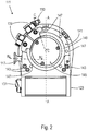
- the turbo-molecular pump 111 shown comprises a pump inlet 115 which is surrounded by an inlet flange 113 and to which a recipient (not shown) can be connected in a manner known per se.
- the gas from the recipient can be sucked out of the recipient via the pump inlet 115 and conveyed through the pump to a pump outlet 117 to which a backing pump, such as a rotary vane pump, can be connected.
- the inlet flange 113 forms according to FIG Fig. 1 the upper end of the housing 119 of the vacuum pump 111.
- the housing 119 comprises a lower part 121, also referred to here as the first housing part, on which an electronics housing 123 is arranged laterally, and a second housing part 122 connected to the lower housing part 121 (see FIG Fig. 6 ), which is also referred to as intermediate piece 122 here.
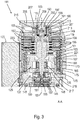
- Electrical and / or electronic components of the vacuum pump 111 are accommodated in the electronics housing 123, for example for operating an electric motor 125 arranged in the vacuum pump (see also FIG Fig. 3 ).
- Several connections 127 for accessories are provided on the electronics housing 123.
- a data interface 129 for example in accordance with the RS485 standard, and a power supply connection 131 are arranged on the electronics housing 123.
- turbomolecular pumps that do not have an electronic housing attached in this way, but are connected to external drive electronics.
- a flood inlet 133 in particular in the form of a flood valve, is provided on the housing 119 of the turbo molecular pump 111, via which the vacuum pump 111 can be flooded.
- a sealing gas connection 135, which is also referred to as a purging gas connection via which purging gas to protect the electric motor 125 (see e.g. Fig. 3 ) can be admitted into the engine compartment 137, in which the electric motor 125 in the vacuum pump 111 is accommodated, before the gas conveyed by the pump.
- Two coolant connections 139 are also arranged in the lower part 121, one of the coolant connections being provided as an inlet and the other coolant connection being provided as an outlet for coolant which can be passed into the vacuum pump for cooling purposes.
- Other existing turbo-molecular vacuum pumps (not shown) are operated exclusively with air cooling.
- the lower side 141 of the vacuum pump can serve as a standing surface, so that the vacuum pump 111 can be operated standing on the lower side 141.
- the vacuum pump 111 can, however, also be attached to a recipient via the inlet flange 113 and can thus be operated in a suspended manner, as it were.
- the vacuum pump 111 can be designed in such a way that it can also be put into operation when it is oriented in a different way than in FIG Fig. 1 is shown.
- Embodiments of the vacuum pump can also be implemented in which the underside 141 cannot be arranged facing downwards, but facing to the side or facing upwards. In principle, any angle is possible.
- a bearing cap 145 is attached to the underside 141.
- Fastening bores 147 are also arranged on the underside 141, via which the pump 111 can be fastened to a support surface, for example. This is not possible with other existing turbo-molecular vacuum pumps (not shown), which are in particular larger than the pump shown here.
- a coolant line 148 is shown, in which the coolant introduced and discharged via the coolant connections 139 can circulate.
- the vacuum pump comprises several process gas pump stages for conveying the process gas present at the pump inlet 115 to the pump outlet 117.
- a rotor 149 is arranged in the housing 119 and has a rotor shaft 153 rotatable about an axis of rotation 151.
- the turbomolecular pump 111 comprises several turbomolecular pump stages connected in series with one another for effective pumping, with several radial rotor disks 155 fastened to the rotor shaft 153 and stator disks 157 arranged between the rotor disks 155 and fixed in the housing 119 a rotor disk 155 and an adjacent stator disk 157 each have a turbomolecular pumping stage.
- the stator disks 157 are held at a desired axial distance from one another by spacer rings 159.
- the vacuum pump also comprises Holweck pump stages which are arranged one inside the other in the radial direction and are connected in series with one another for effective pumping. There are other turbo-molecular vacuum pumps (not shown) that do not have Holweck pump stages.
- the rotor of the Holweck pump stages comprises a rotor hub 161 arranged on the rotor shaft 153 and two cylinder-shell-shaped Holweck rotor sleeves 163, 165 which are attached to the rotor hub 161 and carried by the latter, which are oriented coaxially to the axis of rotation 151 and nested in one another in the radial direction. Furthermore, two cylinder jacket-shaped Holweck stator sleeves 167, 169 are provided, which are also oriented coaxially to the axis of rotation 151 and, viewed in the radial direction, are nested inside one another.
- the active pumping surfaces of the Holweck pump stages are formed by the jacket surfaces, that is to say by the radial inner and / or outer surfaces, of the Holweck rotor sleeves 163, 165 and the Holweck stator sleeves 167, 169.
- the radial inner surface of the outer Holweck stator sleeve 167 lies opposite the radial outer surface of the outer Holweck rotor sleeve 163, forming a radial Holweck gap 171 and with this forms the first Holweck pumping stage following the turbo molecular pumps.
- the radial inner surface of the outer Holweck rotor sleeve 163 is opposite the radial outer surface of the inner Holweck stator sleeve 169 with the formation of a radial Holweck gap 173 and forms with this a second Holweck pump stage.
- the radial inner surface of the inner Holweck stator sleeve 169 lies opposite the radial outer surface of the inner Holweck rotor sleeve 165 with the formation of a radial Holweck gap 175 and with this forms the third Holweck pumping stage.
- a radially running channel can be provided, via which the radially outer Holweck gap 171 is connected to the central Holweck gap 173.
- a radially running channel can be provided at the upper end of the inner Holweck stator sleeve 169, via which the middle Holweck gap 173 is connected to the radially inner Holweck gap 175.
- the nested Holweck pump stages are connected in series with one another.
- a connection channel 179 to the outlet 117 can also be provided.
- the aforementioned pump-active surfaces of the Holweck stator sleeves 167, 169 each have a plurality of Holweck grooves running helically around the axis of rotation 151 in the axial direction, while the opposing lateral surfaces of the Holweck rotor sleeves 163, 165 are smooth and the gas for operating the Drive vacuum pump 111 in the Holweck grooves.
- a roller bearing 181 is provided in the area of the pump outlet 117 and a permanent magnetic bearing 183 in the area of the pump inlet 115.
- a conical injection molded nut 185 is provided on the rotor shaft 153 with an outer diameter that increases towards the roller bearing 181.
- the injection-molded nut 185 is in sliding contact with at least one stripper of an operating medium store.
- an injection screw can be provided instead of an injection nut. Since different designs are thus possible, the term "spray tip" is also used in this context.
- the operating medium reservoir comprises several absorbent discs 187 stacked on top of one another, which are impregnated with an operating medium for the roller bearing 181, for example with a lubricant.
- the operating medium is transferred by capillary action from the operating medium reservoir via the scraper to the rotating injection nut 185 and, as a result of the centrifugal force, is conveyed along the injection nut 185 in the direction of the increasing outer diameter of the injection nut 185 to the roller bearing 181, where it eg fulfills a lubricating function.
- the roller bearing 181 and the operating medium store are enclosed in the vacuum pump by a trough-shaped insert 189 and the bearing cover 145.
- the permanent magnetic bearing 183 comprises a rotor-side bearing half 191 and a stator-side bearing half 193, each of which comprises a ring stack of several permanent magnetic rings 195, 197 stacked on top of one another in the axial direction.
- the ring magnets 195, 197 are opposite one another with the formation of a radial bearing gap 199, the rotor-side ring magnets 195 being arranged radially on the outside and the stator-side ring magnets 197 being arranged radially on the inside.
- the magnetic field present in the bearing gap 199 causes magnetic repulsive forces between the ring magnets 195, 197, which cause the rotor shaft 153 to be supported radially.
- the rotor-side ring magnets 195 are carried by a carrier section 201 of the rotor shaft 153 which surrounds the ring magnets 195 radially on the outside.
- the stator-side ring magnets 197 are carried by a stator-side support section 203 which extends through the ring magnets 197 and is suspended from radial struts 205 of the housing 119.
- the ring magnets 195 on the rotor side are fixed parallel to the axis of rotation 151 by a cover element 207 coupled to the carrier section 201.
- the stator-side ring magnets 197 are parallel to the axis of rotation 151 in one direction by a fastening ring 209 connected to the carrier section 203 and one connected to the carrier section 203 Fixing ring 211 set.
- a plate spring 213 can also be provided between the fastening ring 211 and the ring magnet 197.
- An emergency or retainer bearing 215 is provided inside the magnetic bearing, which runs empty during normal operation of the vacuum pump 111 without contact and only comes into engagement with an excessive radial deflection of the rotor 149 relative to the stator to create a radial stop for the rotor 149 to form so that a collision of the rotor-side structures with the stator-side structures is prevented.
- the backup bearing 215 is designed as an unlubricated roller bearing and forms a radial gap with the rotor 149 and / or the stator, which has the effect that the backup bearing 215 is disengaged during normal pumping operation.
- the radial deflection at which the backup bearing 215 engages is dimensioned large enough that the backup bearing 215 does not come into engagement during normal operation of the vacuum pump, and at the same time small enough so that a collision of the rotor-side structures with the stator-side structures under all circumstances is prevented.
- the vacuum pump 111 comprises the electric motor 125 for rotatingly driving the rotor 149.
- the armature of the electric motor 125 is formed by the rotor 149, the rotor shaft 153 of which extends through the motor stator 217.
- a permanent magnet arrangement can be arranged radially on the outside or embedded in the section of the rotor shaft 153 extending through the motor stator 217.
- the motor stator 217 is fixed in the housing within the motor compartment 137 provided for the electric motor 125.
- a sealing gas which is also referred to as a flushing gas and which can be air or nitrogen, for example, can enter the engine compartment 137 via the sealing gas connection 135.
- the electric motor 125 can be protected from process gas, e.g. from corrosive components of the process gas, via the sealing gas.
- the engine compartment 137 can also be evacuated via the pump outlet 117, i.e. in the engine compartment 137 there is at least approximately the vacuum pressure produced by the backing pump connected to the pump outlet 117.
- a so-called labyrinth seal 223, known per se, can also be provided between the rotor hub 161 and a wall 221 delimiting the engine compartment 137, in particular in order to achieve a better sealing of the motor compartment 217 from the Holweck pump stages located radially outside.
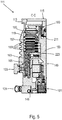
- the turbo molecular pump 230 differs from the turbo-molecular pump 111, as described above with reference to FIG Figs. 1 to 5 has been described, inter alia by the fact that the turbo molecular pump 230 Fig. 6 no Holweck pump stages are provided in the transition area between the lower housing part 121 and the intermediate piece 122, which is, however, of no significance for the present invention. Rather, the two housing parts - lower housing part 121 and intermediate piece - are at this point 122 - connected to one another via a screw 232 such as a hexagon socket screw or a screw with a hexalobular head.
- a screw 232 such as a hexagon socket screw or a screw with a hexalobular head.
- the housing part 121 has a circumferential housing wall 236 which extends in the axial direction with respect to the axis of rotation 151 and has a circumferential end face 238 and a bottom face 141 opposite the end face 238 in the axial direction, which likewise forms the underside 141 of the pump housing 119 .
- the second housing part or the intermediate piece 122 also has a circumferential housing wall 240 which extends in the axial direction in relation to the axis of rotation 151 and has a circumferential end face 242.
- the two housing parts 121, 122 adjoin one another in such a way that the end face 242 of the intermediate piece 122 rests against the end face 238 of the housing lower part 121.
- the two housing parts 121, 122 are connected to one another via several screws 232, of which only one is shown here.
- a stepped bore 234 which is formed in the housing wall 236 of the lower housing part 121 and extends between the bottom surface or the underside 141 and the end face 238 of the lower housing part 221.
- the stepped bore 234 extends with respect to the axis of rotation 151 in the axial direction of the axis of rotation 151 of the pump mechanism received by the housing 119 and comprises a first bore section 244, which opens into the bottom surface 141 or ends at it, and a second bore section 246, which in the end face 238 of the lower housing part 121 opens or ends there.
- the first bore section 244 has a larger diameter than the second bore section 246, with the result that the stepped bore 234 forms an annular circumferential step or an annular shoulder 248 in the transition area between the two bore sections 244, 246.
- the screw shaft 250 of the screw 232 extends through the second bore section 246, the free end of the screw shaft 250 being screwed into a threaded bore 254 formed in the housing wall 240 of the intermediate piece 122.
- the screw head 252 of the screw 232 is supported on the annular shoulder 248 of the stepped bore 234, so that the two housing parts 121, 122 are braced against one another when the screw 232 is tightened.
- the first bore section 244 of the stepped bore 234 contains an internal thread 256 into which the threaded shaft 258 of a fastening screw 260 can be screwed in order to be able to attach the lower housing part 221 and thus the entire pump 230 to a fastening structure 262.
- the first bore section 244 itself forms the internal thread 256, for which purpose the internal thread 256 is cut into the inner circumferential surface of the first bore section 244.
- the internal thread can also be formed, for example, by a threaded sleeve which the first bore section 244 receives and which is secured therein, for example by means of a grub screw.
- the length of the internal thread 256 corresponds approximately to 2.5 to 3 times the diameter of the first bore section 244 or the threaded shaft 258 of the fastening screw 260, whereby the turbo molecular pump 230 is reliably secured against lifting forces on the fastening structure 262 leaves.
- the fastening screw 260 extends through a stepped bore 264 formed in the fastening structure 262, with its threaded shaft 258 being screwed into the internal thread 256 of the first bore section 244 of the stepped bore 234 is formed in the housing wall 236 of the lower housing part 121.
- the screw head 268 of the fastening screw 260 is supported on the annular shoulder 266 of the stepped bore 264, so that the underside 141 of the lower housing part 121 and thus the entire pump 230 is braced against the fastening structure 262 when the fastening screw 260 is tightened.
- fastening screw 262 is screwed into the same stepped bore 234 that is also used to accommodate the screw 232, by means of which the two housing parts 221, 222 are connected to one another, there is no additional space in the lower housing part 121 or on its underside 141 to provide threaded openings required, into which the fastening screw 260 can be screwed.
- a sufficient number of fastening screws 260 can thus be used to secure the turbomolecular pump 230 to the fastening structure 262, and these fastening screws 260 can also have a relatively large shaft diameter, since the first bore section 244 of the stepped bore 234 naturally has a larger diameter than the second bore diameter 246 has. Crash moments occurring in the event of a fault can thus be reliably transmitted to the fastening structure 262 via the fastening screws 260.
Landscapes
- Engineering & Computer Science (AREA)
- General Engineering & Computer Science (AREA)
- Mechanical Engineering (AREA)
- Non-Positive Displacement Air Blowers (AREA)
Priority Applications (2)
| Application Number | Priority Date | Filing Date | Title |
|---|---|---|---|
| EP20183950.3A EP3760872B1 (fr) | 2020-07-03 | 2020-07-03 | Pompe à vide pourvue d'un agencement de fixation destiné à l'application de la pompe à une structure de fixation ainsi qu'un poste de pompage doté d'une telle pompe à vide montée sur celui-ci |
| JP2021065646A JP7091518B2 (ja) | 2020-07-03 | 2021-04-08 | ポンプを固定構造に取り付けるための固定措置を備えた真空ポンプと、そのように真空ポンプを取り付けたポンプスタンド |
Applications Claiming Priority (1)
| Application Number | Priority Date | Filing Date | Title |
|---|---|---|---|
| EP20183950.3A EP3760872B1 (fr) | 2020-07-03 | 2020-07-03 | Pompe à vide pourvue d'un agencement de fixation destiné à l'application de la pompe à une structure de fixation ainsi qu'un poste de pompage doté d'une telle pompe à vide montée sur celui-ci |
Publications (2)
| Publication Number | Publication Date |
|---|---|
| EP3760872A1 true EP3760872A1 (fr) | 2021-01-06 |
| EP3760872B1 EP3760872B1 (fr) | 2022-06-08 |
Family
ID=71614680
Family Applications (1)
| Application Number | Title | Priority Date | Filing Date |
|---|---|---|---|
| EP20183950.3A Active EP3760872B1 (fr) | 2020-07-03 | 2020-07-03 | Pompe à vide pourvue d'un agencement de fixation destiné à l'application de la pompe à une structure de fixation ainsi qu'un poste de pompage doté d'une telle pompe à vide montée sur celui-ci |
Country Status (2)
| Country | Link |
|---|---|
| EP (1) | EP3760872B1 (fr) |
| JP (1) | JP7091518B2 (fr) |
Cited By (1)
| Publication number | Priority date | Publication date | Assignee | Title |
|---|---|---|---|---|
| CN118766258A (zh) * | 2023-04-07 | 2024-10-15 | 深圳市韶音科技有限公司 | 展示台、展示装置、连接结构和紧固件 |
Citations (3)
| Publication number | Priority date | Publication date | Assignee | Title |
|---|---|---|---|---|
| FR2611818A1 (fr) * | 1987-02-26 | 1988-09-09 | Cit Alcatel | Pompe rotative a vide moleculaire du type a canal de gaede |
| JPH10299774A (ja) * | 1997-04-25 | 1998-11-10 | Daikin Ind Ltd | 磁気軸受装置 |
| US20130115074A1 (en) * | 2011-11-09 | 2013-05-09 | Shingo TSUTSUI | Turbo molecular pump device |
Family Cites Families (6)
| Publication number | Priority date | Publication date | Assignee | Title |
|---|---|---|---|---|
| JP3879169B2 (ja) * | 1997-03-31 | 2007-02-07 | 株式会社島津製作所 | ターボ分子ポンプ |
| US6298534B1 (en) * | 1997-11-21 | 2001-10-09 | Applied Materials, Inc. | Chamber component removal system, apparatus and method |
| JP4126212B2 (ja) * | 2001-11-19 | 2008-07-30 | エドワーズ株式会社 | 真空ポンプ |
| JP2006063969A (ja) * | 2004-07-30 | 2006-03-09 | Shimadzu Corp | 回転式真空ポンプ、真空装置およびポンプ接続構造 |
| JP2019186996A (ja) * | 2018-04-03 | 2019-10-24 | 本田技研工業株式会社 | 回転電機及び回転電機の振動抑制構造 |
| JP7147401B2 (ja) * | 2018-09-12 | 2022-10-05 | 株式会社島津製作所 | ターボ分子ポンプ |
-
2020
- 2020-07-03 EP EP20183950.3A patent/EP3760872B1/fr active Active
-
2021
- 2021-04-08 JP JP2021065646A patent/JP7091518B2/ja active Active
Patent Citations (3)
| Publication number | Priority date | Publication date | Assignee | Title |
|---|---|---|---|---|
| FR2611818A1 (fr) * | 1987-02-26 | 1988-09-09 | Cit Alcatel | Pompe rotative a vide moleculaire du type a canal de gaede |
| JPH10299774A (ja) * | 1997-04-25 | 1998-11-10 | Daikin Ind Ltd | 磁気軸受装置 |
| US20130115074A1 (en) * | 2011-11-09 | 2013-05-09 | Shingo TSUTSUI | Turbo molecular pump device |
Non-Patent Citations (1)
| Title |
|---|
| FREDRIK RAMBRIS: "Two screws in one hole", YOUTUBE, 28 May 2015 (2015-05-28), pages 1 pp., XP054981121, Retrieved from the Internet <URL:https://www.youtube.com/watch?v=gRXJ3Cgjd88> [retrieved on 20201119] * |
Cited By (1)
| Publication number | Priority date | Publication date | Assignee | Title |
|---|---|---|---|---|
| CN118766258A (zh) * | 2023-04-07 | 2024-10-15 | 深圳市韶音科技有限公司 | 展示台、展示装置、连接结构和紧固件 |
Also Published As
| Publication number | Publication date |
|---|---|
| JP2022013675A (ja) | 2022-01-18 |
| EP3760872B1 (fr) | 2022-06-08 |
| JP7091518B2 (ja) | 2022-06-27 |
Similar Documents
| Publication | Publication Date | Title |
|---|---|---|
| EP3657021A1 (fr) | Pompe à vide | |
| EP4108932B1 (fr) | Reciate et système avec reciate et pompe à vide élevé | |
| EP3845764A2 (fr) | Pompe à vide et système de pompe à vide | |
| EP3670924B1 (fr) | Pompe à vide et procédé de fabrication d'une telle pompe à vide | |
| DE102015104438B4 (de) | Vakuumsystem | |
| EP3760872B1 (fr) | Pompe à vide pourvue d'un agencement de fixation destiné à l'application de la pompe à une structure de fixation ainsi qu'un poste de pompage doté d'une telle pompe à vide montée sur celui-ci | |
| EP3730802B1 (fr) | Élément de bride | |
| EP3135932B1 (fr) | Pompe à vide et palier à aimant permanent | |
| EP3926175A1 (fr) | Pompe à vide dotée d'un palier à roulement | |
| EP4194700B1 (fr) | Pompe à vide avec étage de pompe de holweck à géométrie de holweck variable | |
| EP4325061A1 (fr) | Pompe à vide turbomoléculaire | |
| EP4144994B1 (fr) | Dispositif et procédé d'évaluation d'un palier magnétique | |
| EP3907406B1 (fr) | Pompe à vide | |
| EP3196471B1 (fr) | Pompe a vide | |
| EP4108930B1 (fr) | Pompe à vide dotée d'un support d'aimants réglable dans une direction axiale | |
| EP4212730A1 (fr) | Pompe à vide avec étage de pompage de holward optimisé pour compenser la perte de performance liée à la température | |
| DE102020116770B4 (de) | Vakuumpumpe mit integriertem miniaturventil | |
| EP3628883B1 (fr) | Pompe à vide | |
| EP3597926B1 (fr) | Pompe à vide | |
| EP3561307B1 (fr) | Pompe à vide avec une bride de port d'aspiration et un support de palier dans le port d'aspiration | |
| EP4273405B1 (fr) | Pompe à vide avec un étage de pompage de type holweck avec une géométrie holweck variable | |
| EP4293232B1 (fr) | Pompe turbomoléculaire | |
| EP4328468B1 (fr) | Soupape et pompe à vide équipée d'une telle soupape | |
| EP4269804B1 (fr) | Pompe à vide | |
| EP4155549B1 (fr) | Pompe à vide à capacité d'aspiration améliorée de l'étage de pompage holweck |
Legal Events
| Date | Code | Title | Description |
|---|---|---|---|
| PUAI | Public reference made under article 153(3) epc to a published international application that has entered the european phase |
Free format text: ORIGINAL CODE: 0009012 |
|
| STAA | Information on the status of an ep patent application or granted ep patent |
Free format text: STATUS: THE APPLICATION HAS BEEN PUBLISHED |
|
| STAA | Information on the status of an ep patent application or granted ep patent |
Free format text: STATUS: REQUEST FOR EXAMINATION WAS MADE |
|
| AK | Designated contracting states |
Kind code of ref document: A1 Designated state(s): AL AT BE BG CH CY CZ DE DK EE ES FI FR GB GR HR HU IE IS IT LI LT LU LV MC MK MT NL NO PL PT RO RS SE SI SK SM TR |
|
| AX | Request for extension of the european patent |
Extension state: BA ME |
|
| 17P | Request for examination filed |
Effective date: 20201214 |
|
| RBV | Designated contracting states (corrected) |
Designated state(s): AL AT BE BG CH CY CZ DE DK EE ES FI FR GB GR HR HU IE IS IT LI LT LU LV MC MK MT NL NO PL PT RO RS SE SI SK SM TR |
|
| GRAP | Despatch of communication of intention to grant a patent |
Free format text: ORIGINAL CODE: EPIDOSNIGR1 |
|
| STAA | Information on the status of an ep patent application or granted ep patent |
Free format text: STATUS: GRANT OF PATENT IS INTENDED |
|
| INTG | Intention to grant announced |
Effective date: 20220310 |
|
| GRAS | Grant fee paid |
Free format text: ORIGINAL CODE: EPIDOSNIGR3 |
|
| GRAA | (expected) grant |
Free format text: ORIGINAL CODE: 0009210 |
|
| STAA | Information on the status of an ep patent application or granted ep patent |
Free format text: STATUS: THE PATENT HAS BEEN GRANTED |
|
| AK | Designated contracting states |
Kind code of ref document: B1 Designated state(s): AL AT BE BG CH CY CZ DE DK EE ES FI FR GB GR HR HU IE IS IT LI LT LU LV MC MK MT NL NO PL PT RO RS SE SI SK SM TR |
|
| REG | Reference to a national code |
Ref country code: AT Ref legal event code: REF Ref document number: 1497105 Country of ref document: AT Kind code of ref document: T Effective date: 20220615 Ref country code: CH Ref legal event code: EP |
|
| REG | Reference to a national code |
Ref country code: DE Ref legal event code: R096 Ref document number: 502020001200 Country of ref document: DE |
|
| REG | Reference to a national code |
Ref country code: IE Ref legal event code: FG4D Free format text: LANGUAGE OF EP DOCUMENT: GERMAN |
|
| REG | Reference to a national code |
Ref country code: LT Ref legal event code: MG9D |
|
| REG | Reference to a national code |
Ref country code: NL Ref legal event code: MP Effective date: 20220608 |
|
| PG25 | Lapsed in a contracting state [announced via postgrant information from national office to epo] |
Ref country code: SE Free format text: LAPSE BECAUSE OF FAILURE TO SUBMIT A TRANSLATION OF THE DESCRIPTION OR TO PAY THE FEE WITHIN THE PRESCRIBED TIME-LIMIT Effective date: 20220608 Ref country code: NO Free format text: LAPSE BECAUSE OF FAILURE TO SUBMIT A TRANSLATION OF THE DESCRIPTION OR TO PAY THE FEE WITHIN THE PRESCRIBED TIME-LIMIT Effective date: 20220908 Ref country code: LT Free format text: LAPSE BECAUSE OF FAILURE TO SUBMIT A TRANSLATION OF THE DESCRIPTION OR TO PAY THE FEE WITHIN THE PRESCRIBED TIME-LIMIT Effective date: 20220608 Ref country code: HR Free format text: LAPSE BECAUSE OF FAILURE TO SUBMIT A TRANSLATION OF THE DESCRIPTION OR TO PAY THE FEE WITHIN THE PRESCRIBED TIME-LIMIT Effective date: 20220608 Ref country code: GR Free format text: LAPSE BECAUSE OF FAILURE TO SUBMIT A TRANSLATION OF THE DESCRIPTION OR TO PAY THE FEE WITHIN THE PRESCRIBED TIME-LIMIT Effective date: 20220909 Ref country code: FI Free format text: LAPSE BECAUSE OF FAILURE TO SUBMIT A TRANSLATION OF THE DESCRIPTION OR TO PAY THE FEE WITHIN THE PRESCRIBED TIME-LIMIT Effective date: 20220608 Ref country code: BG Free format text: LAPSE BECAUSE OF FAILURE TO SUBMIT A TRANSLATION OF THE DESCRIPTION OR TO PAY THE FEE WITHIN THE PRESCRIBED TIME-LIMIT Effective date: 20220908 |
|
| PG25 | Lapsed in a contracting state [announced via postgrant information from national office to epo] |
Ref country code: RS Free format text: LAPSE BECAUSE OF FAILURE TO SUBMIT A TRANSLATION OF THE DESCRIPTION OR TO PAY THE FEE WITHIN THE PRESCRIBED TIME-LIMIT Effective date: 20220608 Ref country code: LV Free format text: LAPSE BECAUSE OF FAILURE TO SUBMIT A TRANSLATION OF THE DESCRIPTION OR TO PAY THE FEE WITHIN THE PRESCRIBED TIME-LIMIT Effective date: 20220608 |
|
| PG25 | Lapsed in a contracting state [announced via postgrant information from national office to epo] |
Ref country code: NL Free format text: LAPSE BECAUSE OF FAILURE TO SUBMIT A TRANSLATION OF THE DESCRIPTION OR TO PAY THE FEE WITHIN THE PRESCRIBED TIME-LIMIT Effective date: 20220608 |
|
| PG25 | Lapsed in a contracting state [announced via postgrant information from national office to epo] |
Ref country code: SM Free format text: LAPSE BECAUSE OF FAILURE TO SUBMIT A TRANSLATION OF THE DESCRIPTION OR TO PAY THE FEE WITHIN THE PRESCRIBED TIME-LIMIT Effective date: 20220608 Ref country code: SK Free format text: LAPSE BECAUSE OF FAILURE TO SUBMIT A TRANSLATION OF THE DESCRIPTION OR TO PAY THE FEE WITHIN THE PRESCRIBED TIME-LIMIT Effective date: 20220608 Ref country code: RO Free format text: LAPSE BECAUSE OF FAILURE TO SUBMIT A TRANSLATION OF THE DESCRIPTION OR TO PAY THE FEE WITHIN THE PRESCRIBED TIME-LIMIT Effective date: 20220608 Ref country code: PT Free format text: LAPSE BECAUSE OF FAILURE TO SUBMIT A TRANSLATION OF THE DESCRIPTION OR TO PAY THE FEE WITHIN THE PRESCRIBED TIME-LIMIT Effective date: 20221010 Ref country code: ES Free format text: LAPSE BECAUSE OF FAILURE TO SUBMIT A TRANSLATION OF THE DESCRIPTION OR TO PAY THE FEE WITHIN THE PRESCRIBED TIME-LIMIT Effective date: 20220608 Ref country code: EE Free format text: LAPSE BECAUSE OF FAILURE TO SUBMIT A TRANSLATION OF THE DESCRIPTION OR TO PAY THE FEE WITHIN THE PRESCRIBED TIME-LIMIT Effective date: 20220608 |
|
| PG25 | Lapsed in a contracting state [announced via postgrant information from national office to epo] |
Ref country code: PL Free format text: LAPSE BECAUSE OF FAILURE TO SUBMIT A TRANSLATION OF THE DESCRIPTION OR TO PAY THE FEE WITHIN THE PRESCRIBED TIME-LIMIT Effective date: 20220608 Ref country code: IS Free format text: LAPSE BECAUSE OF FAILURE TO SUBMIT A TRANSLATION OF THE DESCRIPTION OR TO PAY THE FEE WITHIN THE PRESCRIBED TIME-LIMIT Effective date: 20221008 |
|
| REG | Reference to a national code |
Ref country code: DE Ref legal event code: R097 Ref document number: 502020001200 Country of ref document: DE |
|
| REG | Reference to a national code |
Ref country code: BE Ref legal event code: MM Effective date: 20220731 |
|
| PG25 | Lapsed in a contracting state [announced via postgrant information from national office to epo] |
Ref country code: MC Free format text: LAPSE BECAUSE OF FAILURE TO SUBMIT A TRANSLATION OF THE DESCRIPTION OR TO PAY THE FEE WITHIN THE PRESCRIBED TIME-LIMIT Effective date: 20220608 Ref country code: AL Free format text: LAPSE BECAUSE OF FAILURE TO SUBMIT A TRANSLATION OF THE DESCRIPTION OR TO PAY THE FEE WITHIN THE PRESCRIBED TIME-LIMIT Effective date: 20220608 |
|
| PLBE | No opposition filed within time limit |
Free format text: ORIGINAL CODE: 0009261 |
|
| STAA | Information on the status of an ep patent application or granted ep patent |
Free format text: STATUS: NO OPPOSITION FILED WITHIN TIME LIMIT |
|
| PG25 | Lapsed in a contracting state [announced via postgrant information from national office to epo] |
Ref country code: LU Free format text: LAPSE BECAUSE OF NON-PAYMENT OF DUE FEES Effective date: 20220703 Ref country code: DK Free format text: LAPSE BECAUSE OF FAILURE TO SUBMIT A TRANSLATION OF THE DESCRIPTION OR TO PAY THE FEE WITHIN THE PRESCRIBED TIME-LIMIT Effective date: 20220608 |
|
| 26N | No opposition filed |
Effective date: 20230310 |
|
| PG25 | Lapsed in a contracting state [announced via postgrant information from national office to epo] |
Ref country code: SI Free format text: LAPSE BECAUSE OF FAILURE TO SUBMIT A TRANSLATION OF THE DESCRIPTION OR TO PAY THE FEE WITHIN THE PRESCRIBED TIME-LIMIT Effective date: 20220608 Ref country code: BE Free format text: LAPSE BECAUSE OF NON-PAYMENT OF DUE FEES Effective date: 20220731 |
|
| PG25 | Lapsed in a contracting state [announced via postgrant information from national office to epo] |
Ref country code: IE Free format text: LAPSE BECAUSE OF NON-PAYMENT OF DUE FEES Effective date: 20220703 Ref country code: FR Free format text: LAPSE BECAUSE OF NON-PAYMENT OF DUE FEES Effective date: 20220808 |
|
| REG | Reference to a national code |
Ref country code: CH Ref legal event code: PL |
|
| PG25 | Lapsed in a contracting state [announced via postgrant information from national office to epo] |
Ref country code: MK Free format text: LAPSE BECAUSE OF FAILURE TO SUBMIT A TRANSLATION OF THE DESCRIPTION OR TO PAY THE FEE WITHIN THE PRESCRIBED TIME-LIMIT Effective date: 20220608 Ref country code: CY Free format text: LAPSE BECAUSE OF FAILURE TO SUBMIT A TRANSLATION OF THE DESCRIPTION OR TO PAY THE FEE WITHIN THE PRESCRIBED TIME-LIMIT Effective date: 20220608 Ref country code: CH Free format text: LAPSE BECAUSE OF NON-PAYMENT OF DUE FEES Effective date: 20230731 |
|
| PG25 | Lapsed in a contracting state [announced via postgrant information from national office to epo] |
Ref country code: HU Free format text: LAPSE BECAUSE OF FAILURE TO SUBMIT A TRANSLATION OF THE DESCRIPTION OR TO PAY THE FEE WITHIN THE PRESCRIBED TIME-LIMIT; INVALID AB INITIO Effective date: 20200703 |
|
| PG25 | Lapsed in a contracting state [announced via postgrant information from national office to epo] |
Ref country code: MT Free format text: LAPSE BECAUSE OF FAILURE TO SUBMIT A TRANSLATION OF THE DESCRIPTION OR TO PAY THE FEE WITHIN THE PRESCRIBED TIME-LIMIT Effective date: 20220608 |
|
| PG25 | Lapsed in a contracting state [announced via postgrant information from national office to epo] |
Ref country code: BG Free format text: LAPSE BECAUSE OF FAILURE TO SUBMIT A TRANSLATION OF THE DESCRIPTION OR TO PAY THE FEE WITHIN THE PRESCRIBED TIME-LIMIT Effective date: 20220608 |
|
| PG25 | Lapsed in a contracting state [announced via postgrant information from national office to epo] |
Ref country code: BG Free format text: LAPSE BECAUSE OF FAILURE TO SUBMIT A TRANSLATION OF THE DESCRIPTION OR TO PAY THE FEE WITHIN THE PRESCRIBED TIME-LIMIT Effective date: 20220608 |
|
| PGFP | Annual fee paid to national office [announced via postgrant information from national office to epo] |
Ref country code: CZ Payment date: 20250625 Year of fee payment: 6 |
|
| PGFP | Annual fee paid to national office [announced via postgrant information from national office to epo] |
Ref country code: IT Payment date: 20250724 Year of fee payment: 6 |
|
| PGFP | Annual fee paid to national office [announced via postgrant information from national office to epo] |
Ref country code: GB Payment date: 20250722 Year of fee payment: 6 |
|
| PGFP | Annual fee paid to national office [announced via postgrant information from national office to epo] |
Ref country code: AT Payment date: 20251020 Year of fee payment: 5 |
|
| PG25 | Lapsed in a contracting state [announced via postgrant information from national office to epo] |
Ref country code: TR Free format text: LAPSE BECAUSE OF FAILURE TO SUBMIT A TRANSLATION OF THE DESCRIPTION OR TO PAY THE FEE WITHIN THE PRESCRIBED TIME-LIMIT Effective date: 20220608 |
|
| PGFP | Annual fee paid to national office [announced via postgrant information from national office to epo] |
Ref country code: DE Payment date: 20250926 Year of fee payment: 6 |