EP1843043A2 - Pompe à vide avec un appareil d'entraînement - Google Patents
Pompe à vide avec un appareil d'entraînement Download PDFInfo
- Publication number
- EP1843043A2 EP1843043A2 EP07006199A EP07006199A EP1843043A2 EP 1843043 A2 EP1843043 A2 EP 1843043A2 EP 07006199 A EP07006199 A EP 07006199A EP 07006199 A EP07006199 A EP 07006199A EP 1843043 A2 EP1843043 A2 EP 1843043A2
- Authority
- EP
- European Patent Office
- Prior art keywords
- vacuum pump
- interior
- separating element
- housing
- circuit board
- Prior art date
- Legal status (The legal status is an assumption and is not a legal conclusion. Google has not performed a legal analysis and makes no representation as to the accuracy of the status listed.)
- Granted
Links
Images
Classifications
-
- F—MECHANICAL ENGINEERING; LIGHTING; HEATING; WEAPONS; BLASTING
- F04—POSITIVE - DISPLACEMENT MACHINES FOR LIQUIDS; PUMPS FOR LIQUIDS OR ELASTIC FLUIDS
- F04D—NON-POSITIVE-DISPLACEMENT PUMPS
- F04D19/00—Axial-flow pumps
- F04D19/02—Multi-stage pumps
- F04D19/04—Multi-stage pumps specially adapted to the production of a high vacuum, e.g. molecular pumps
-
- F—MECHANICAL ENGINEERING; LIGHTING; HEATING; WEAPONS; BLASTING
- F04—POSITIVE - DISPLACEMENT MACHINES FOR LIQUIDS; PUMPS FOR LIQUIDS OR ELASTIC FLUIDS
- F04D—NON-POSITIVE-DISPLACEMENT PUMPS
- F04D17/00—Radial-flow pumps, e.g. centrifugal pumps; Helico-centrifugal pumps
- F04D17/08—Centrifugal pumps
- F04D17/16—Centrifugal pumps for displacing without appreciable compression
- F04D17/168—Pumps specially adapted to produce a vacuum
-
- F—MECHANICAL ENGINEERING; LIGHTING; HEATING; WEAPONS; BLASTING
- F04—POSITIVE - DISPLACEMENT MACHINES FOR LIQUIDS; PUMPS FOR LIQUIDS OR ELASTIC FLUIDS
- F04D—NON-POSITIVE-DISPLACEMENT PUMPS
- F04D25/00—Pumping installations or systems
- F04D25/02—Units comprising pumps and their driving means
- F04D25/06—Units comprising pumps and their driving means the pump being electrically driven
- F04D25/068—Mechanical details of the pump control unit
-
- F—MECHANICAL ENGINEERING; LIGHTING; HEATING; WEAPONS; BLASTING
- F04—POSITIVE - DISPLACEMENT MACHINES FOR LIQUIDS; PUMPS FOR LIQUIDS OR ELASTIC FLUIDS
- F04D—NON-POSITIVE-DISPLACEMENT PUMPS
- F04D25/00—Pumping installations or systems
- F04D25/02—Units comprising pumps and their driving means
- F04D25/06—Units comprising pumps and their driving means the pump being electrically driven
- F04D25/0693—Details or arrangements of the wiring
-
- F—MECHANICAL ENGINEERING; LIGHTING; HEATING; WEAPONS; BLASTING
- F04—POSITIVE - DISPLACEMENT MACHINES FOR LIQUIDS; PUMPS FOR LIQUIDS OR ELASTIC FLUIDS
- F04D—NON-POSITIVE-DISPLACEMENT PUMPS
- F04D29/00—Details, component parts, or accessories
- F04D29/08—Sealings
- F04D29/083—Sealings especially adapted for elastic fluid pumps
Definitions
- the invention relates to a vacuum pump, which is arranged in an environment with a housing, an interior and a drive unit, which contains electronic circuits for controlling arranged in the interior electronic and electrical components, wherein there is negative pressure in the interior, and with a separating element, which Interior and surroundings separate.
- Vacuum pumps have an interior in which an increasing number of electronic components is arranged. Such components are, for example, the electric coils of the motor or Hall probes, which detect the rotation of the shaft, and the like. These arranged within the vacuum pump components are controlled by located outside of the vacuum pump, electronic circuits. These circuits are often placed in a driver. The interior of such a vacuum pump is at a pressure level which is below the atmospheric pressure. This means that the electrical lines that make electrical contact between the electronic circuits and the components arranged in the interior, must be performed by a hermetically sealed passage from the interior to the exterior.
- a common solution in the art is to provide a hermetically sealed plug on the vacuum pump.
- This plug has in the direction of the interior of the vacuum pump pins on which cables are soldered, which lead to the electronic components.
- the size and shape of the vacuum pump has gained in importance in recent years.
- the drive unit should adapt to the housing of the vacuum pump so that it must be constructed around it. Put another way: the housing of the vacuum pump sets the framework for the drive unit.
- the connector used in the prior art turns out to be disadvantageous because it is complicated and has a large footprint.
- the object of the invention is therefore to present a vacuum pump with a separating element between the interior and the environment, which allows the construction of a vacuum-tight and less prone to assembly errors implementation that allows a more flexible design of the electrical signal routing.
- a vacuum pump with the features of the first claim.
- the signal routing can be much better adapted to the spatial specifications.
- the assembly of a board is simpler and less prone to error during assembly due to the more spacious space. It is possible to route signals on the board from the point of implementation to another point on the board to connect to the drive unit from it. Boards themselves are available inexpensively in a wide range of geometric shapes. In addition, they are sufficiently vacuum-tight.
- a first development relates to the design of means for carrying electrical currents and voltages.
- a technically simple and inexpensive solution is to pierce the printed circuit board, pins stuck in these holes and to solder. In this case, a vacuum-tight implementation is guaranteed by the soldering.
- Another development of the means for carrying out the electrical currents and voltages is to provide a hermetically sealed plug on the board. This has contact pins in the direction of the interior of the vacuum pump. On the side facing away from this interior, contacts in the printed circuit board are soldered. With this variant, the vacuum tightness is further increased.
- the invention can be further developed by constructing the printed circuit board from at least two layers. This makes it possible to provide connectors on the surface, which are in electrical contact with an inner, located between the layers and electrically conductive layer. This avoids providing through holes in the printed circuit board for the means for passing the electrical currents and voltages. It is increased in this way, the vacuum-tightness of the arrangement.
- Functions such as fault memory, pump type detection, temperature measurement and the like can be realized without leading electrical signals through a vacuum-tight implementation. Only the unavoidable lines are led into the fore-vacuum area of the vacuum pump, for example for the engine. Everything else can be arranged on the board, which is cheaper and technically easier.
- the number of electronic components that are operated in negative pressure is minimized.
- a temperature sensor is arranged on the board, which is in thermal contact with the housing of the vacuum pump. This can be realized by a direct mechanical contact, even a mechanically deformable thermal conductor between the temperature sensor and the housing is a favorable design. A complex wiring of this sensor in the interior of the vacuum pump is eliminated, a defective temperature sensor can be easily replaced. Safe monitoring of the pump temperature and thus avoiding excessive temperatures can thus be ensured.
- An advantageous development is to releasably attach the drive unit to the vacuum pump, wherein it covers the partition at least partially. As a result, a compact overall system is created and at the same time the separating element is protected against external influences.
- the invention can be further developed by being used on a turbomolecular vacuum pump, since these have a particularly large number of electronic components and require complex control.
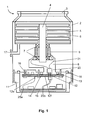
- the first figure shows an example of a vacuum pump, a turbomolecular vacuum pump 1, in short: turbo pump. It has a suction flange 3, via which it is connected to a recipient in which a high vacuum is to be generated.
- the extracted gas is compressed by blades bearing rotor disks 5 and also bearing blades stator 6.
- the rotor disks 5 are set in rapid rotation via a shaft 4 to which they are attached.
- the compressed gas which usually still has a pressure in the coarse / fine vacuum range, is discharged via the gas outlet 17 to a backing pump.
- the shaft is supported rotatably by bearings 7, which are designed, for example, as ball bearings or magnetic bearings.
- the rotation is effected by a drive motor 9.
- the turbo pump has an interior space 8, in which there is a negative pressure compared to the environment of the pump.
- This negative pressure is often in the range of Vorvakuums, which prevails at the gas outlet 17, since the interior and gas outlet are connected to each other via engine and bearing gaps.
- the electrical lines are arranged, via which the electrical power required to generate the rotation is transmitted to the motor 9.
- the drive unit 11 is arranged, which is connected via, for example, releasably connected to the housing of the turbo pump.
- electronic circuits 16 are provided. These circuits take on a variety of tasks, such as the generation of currents and voltages with which the coils of the motor are driven. It can also be provided a mains voltage conditioning, in addition to come integrated circuits and / or controllers, the peripheral devices, such as fans and the like, control. Operating data of the turbo pump can also be monitored or flood processes and the like can be controlled.
- the housing can be sealed via an outer seal 15. This makes it possible to protect the electronic circuit from splashing water, the outer seal is not used to achieve a vacuum tightness.
- the drive unit has the same conditions as the environment, ie normally air at atmospheric pressure.
- the circuits 16 within the drive unit electrical currents and voltages must be fed into the interior 8 of the turbo pump. The pressure difference between the environment and the interior must be maintained.
- a separating element which is provided with means 12 for carrying electrical currents and voltages and covers the opening 23 in the housing of the turbo pump.
- a part of this separator is a printed circuit board 10. This circuit board is pierced in some places. Through the holes electrically conductive pins are inserted and then soldered, so that the holes are sealed vacuum-tight. The pins are connected to the drive unit side facing electrical conductors that make electrical contact with the circuits 16.
- the printed circuit board of the separator is bolted to the pump housing 2 with screws.
- an elastomeric sealing ring 13 surrounds the opening 23.
- the vacuum tightness can be further improved by providing a coating 14 in the region where the elastomeric seal rests on the printed circuit board.
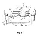
- FIG. 2 A second example of a separating element is shown in Figure 2, in which only the lower part of the pump and the upper part of the drive unit are shown in section.
- the separator here comprises a printed circuit board 10 and a hermetically sealed plug 12c as means for passing electrical currents and voltages.
- This plug has contact pins which sit in holes of the circuit board and are soldered therein. The contact pins lead to the side facing the opening 23 and are connected there to the lines 21.
- An elastomeric sealing ring 24 is disposed between the plug and housing 2 of the turbo pump and seals the interior. To ensure mechanical safety and vacuum tightness, the plug itself is bolted to the pump housing.
- the printed circuit board is also detachable with screws connected to the housing of the vacuum pump.
- On the circuit board further electronic components 31 are arranged. These can be used, for example, to store pump-related data, such as pump type, serial number, etc.
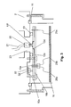
- FIG. 3 Another example of a separating element is shown in Figure 3, in which only the lower part of the pump and the upper part of the drive unit are shown in section.
- the printed circuit board 10 contained in the separating element is constructed here from two layers 10a and 10b, wherein a higher number of layers can also be used. Between the layers, an inner, electrically conductive layer is provided, that is, there are interconnects between the layers 10a and 10b.
- the means for passing electrical currents and voltages herein include connectors 12f mounted on the surface of the printed circuit board, fabricated, for example, in "surface mounting technology” (SMT) technology. These connectors are used in the area of the board that is exposed to negative pressure. The requirements for mechanical stability are low at this point.
- SMT surface mounting technology
- the "surface mounted device” (SMD) connectors can be used wherever high mechanical stability is not required.
- SMD surface mounted device
- a matching plug 20 is plugged, which sits at the ends of the lines 21, which lead to the electrical and electronic components in the interior of the turbo pump.
- Only one layer 10a or 10b penetrating blind holes 12d establish an electrical connection to a conductor track 12b located between the layers. From this conductor track, an electrical connection can be guided via further blind holes and blind holes to the surface of the circuit board facing the drive unit.
- connectors are to be used on the surface facing the drive unit, it is advantageous to first lead the electrical currents and voltages out of the region of the elastomer ring 13 via the conductor track 12b and to bring them to pins 12e, which are soldered into through holes.
- the conductor 12b then ends in a range in which there is no difference between the gas pressure on the surfaces of the layers 10a and 10b, or none of the surfaces is subjected to a negative pressure. Through holes can be used easily in this area. This makes it possible to produce mechanically strong loadable connectors for connection to the circuits 16. With the measures presented in this example, it is possible to avoid holes that pass through the entire printed circuit board in the vacuum critical area within the elastomer seal 13.
- a temperature sensor 30 is also provided on the board.
- This temperature sensor allows the safe monitoring of the pump temperature, so that an excessive operating temperature of the pump detected and countermeasures can be taken. For example, the power fed into the drive can be reduced or the pump even stopped.
- the temperature sensor is in thermal contact with the housing 2. This contact can be achieved in various ways. So it is conceivable to bring the temperature sensor in direct mechanical contact, to press it against the housing. It is also conceivable to provide thermally highly conductive means 32 between the temperature sensor and the housing. It is advantageous to make these means mechanically elastically deformable, so that there is a secure thermal transition from temperature sensor to means and from means to housing.
Landscapes
- Engineering & Computer Science (AREA)
- Mechanical Engineering (AREA)
- General Engineering & Computer Science (AREA)
- Non-Positive Displacement Air Blowers (AREA)
- Compressors, Vaccum Pumps And Other Relevant Systems (AREA)
- Compressor (AREA)
- Applications Or Details Of Rotary Compressors (AREA)
Applications Claiming Priority (1)
| Application Number | Priority Date | Filing Date | Title |
|---|---|---|---|
| DE102006016405.9A DE102006016405B4 (de) | 2006-04-07 | 2006-04-07 | Vakuumpumpe mit Antriebsgerät |
Publications (3)
| Publication Number | Publication Date |
|---|---|
| EP1843043A2 true EP1843043A2 (fr) | 2007-10-10 |
| EP1843043A3 EP1843043A3 (fr) | 2014-04-23 |
| EP1843043B1 EP1843043B1 (fr) | 2018-05-16 |
Family
ID=38051875
Family Applications (1)
| Application Number | Title | Priority Date | Filing Date |
|---|---|---|---|
| EP07006199.9A Active EP1843043B1 (fr) | 2006-04-07 | 2007-03-27 | Pompe à vide avec un dispositif d'entraînement |
Country Status (4)
| Country | Link |
|---|---|
| US (1) | US8651838B2 (fr) |
| EP (1) | EP1843043B1 (fr) |
| JP (1) | JP5303114B2 (fr) |
| DE (1) | DE102006016405B4 (fr) |
Cited By (14)
| Publication number | Priority date | Publication date | Assignee | Title |
|---|---|---|---|---|
| WO2009027485A1 (fr) * | 2007-08-30 | 2009-03-05 | Oerlikon Leybold Vacuum Gmbh | Passage de courant dans une pompe à vide |
| EP2273129A2 (fr) | 2009-07-06 | 2011-01-12 | LTi DRiVES GmbH | Unité de liaison électrique pouvant être raccordée sur une pompe à vide |
| EP3088737A1 (fr) * | 2015-04-30 | 2016-11-02 | Pfeiffer Vacuum Gmbh | Pompe à vide et procédé de production d'une pompe à vide |
| EP1936198B1 (fr) * | 2006-12-13 | 2018-01-24 | Pfeiffer Vacuum Gmbh | Pompe à vide |
| EP3333429A1 (fr) | 2016-12-09 | 2018-06-13 | Pfeiffer Vacuum Gmbh | Appareil a vide |
| EP3339652A1 (fr) | 2016-12-22 | 2018-06-27 | Pfeiffer Vacuum Gmbh | Pompe à vide avec chemise intérieure recueillant des dépôts |
| EP3431769A1 (fr) | 2017-07-21 | 2019-01-23 | Pfeiffer Vacuum Gmbh | Pompe à vide |
| EP3462034A1 (fr) | 2017-09-28 | 2019-04-03 | Pfeiffer Vacuum Gmbh | Pompe à vide |
| EP3470681A1 (fr) * | 2017-10-10 | 2019-04-17 | Pfeiffer Vacuum Gmbh | Traverse électrique pour appareil à vide, sous la forme d'une plaque de circuit imprimé |
| CN109790846A (zh) * | 2016-10-21 | 2019-05-21 | 埃地沃兹日本有限公司 | 真空泵及应用于该真空泵的防水构造、控制装置 |
| EP3626971A1 (fr) * | 2019-08-30 | 2020-03-25 | Pfeiffer Vacuum Gmbh | Pompe à vide |
| EP3803943A1 (fr) * | 2018-05-31 | 2021-04-14 | Micromass UK Limited | Spectromètre de masse |
| US12009193B2 (en) | 2018-05-31 | 2024-06-11 | Micromass Uk Limited | Bench-top Time of Flight mass spectrometer |
| US12027359B2 (en) | 2018-05-31 | 2024-07-02 | Micromass Uk Limited | Bench-top Time of Flight mass spectrometer |
Families Citing this family (22)
| Publication number | Priority date | Publication date | Assignee | Title |
|---|---|---|---|---|
| WO2008096622A1 (fr) * | 2007-02-06 | 2008-08-14 | Edwards Japan Limited | Pompe à vide |
| JP2011144788A (ja) * | 2010-01-18 | 2011-07-28 | Toyota Industries Corp | 電動圧縮機 |
| JP5545358B2 (ja) * | 2010-03-11 | 2014-07-09 | 株式会社島津製作所 | ターボ分子ポンプ装置 |
| JP5353838B2 (ja) * | 2010-07-07 | 2013-11-27 | 株式会社島津製作所 | 真空ポンプ |
| CN103228923B (zh) * | 2010-10-19 | 2016-09-21 | 埃地沃兹日本有限公司 | 真空泵 |
| JP5744044B2 (ja) * | 2010-10-19 | 2015-07-01 | エドワーズ株式会社 | 真空ポンプ |
| ITCO20100067A1 (it) * | 2010-12-23 | 2012-06-24 | Nuovo Pignone Spa | Connessione elettrica per turbomacchina e metodo |
| CN103047152B (zh) * | 2011-10-17 | 2016-06-22 | 株式会社岛津制作所 | 真空泵 |
| JP5673497B2 (ja) * | 2011-11-08 | 2015-02-18 | 株式会社島津製作所 | 一体型ターボ分子ポンプ |
| JP5768670B2 (ja) * | 2011-11-09 | 2015-08-26 | 株式会社島津製作所 | ターボ分子ポンプ装置 |
| JP5963459B2 (ja) * | 2012-01-31 | 2016-08-03 | 住友重機械工業株式会社 | クライオポンプおよびクライオポンプの修理方法 |
| JP5511915B2 (ja) * | 2012-08-28 | 2014-06-04 | 株式会社大阪真空機器製作所 | 分子ポンプ |
| JP6069981B2 (ja) * | 2012-09-10 | 2017-02-01 | 株式会社島津製作所 | ターボ分子ポンプ |
| DE102013222905A1 (de) * | 2013-11-11 | 2015-05-13 | Oerlikon Leybold Vacuum Gmbh | Antriebs- und Steuereinrichtung für eine Vakuumpumpe, Vakuumpumpe sowie Verfahren zum Herstellen einer Steuerplatine für eine Vakuumpumpe |
| JP6449551B2 (ja) * | 2014-03-12 | 2019-01-09 | エドワーズ株式会社 | 真空ポンプの制御装置とこれを備えた真空ポンプ |
| JP6852457B2 (ja) * | 2017-02-27 | 2021-03-31 | 株式会社島津製作所 | 電源一体型真空ポンプ |
| CN111213316B (zh) * | 2017-10-31 | 2021-07-13 | 株式会社爱发科 | 真空泵及其控制方法 |
| CN107986264B (zh) * | 2017-11-28 | 2020-06-30 | 瑞安市任奇科技有限公司 | 一种基于物联网的安全的超声波石墨烯剥离制备装置 |
| JP7088688B2 (ja) * | 2018-02-16 | 2022-06-21 | エドワーズ株式会社 | 真空ポンプと真空ポンプの制御装置 |
| JP7096006B2 (ja) * | 2018-02-16 | 2022-07-05 | エドワーズ株式会社 | 真空ポンプと真空ポンプの制御装置 |
| JP7244328B2 (ja) * | 2019-03-28 | 2023-03-22 | エドワーズ株式会社 | 真空ポンプ及び該真空ポンプの制御装置 |
| DE102021129376A1 (de) | 2021-03-17 | 2022-09-22 | Hanon Systems | Gehäuseeinheit für ein elektronisches Bauteil eines elektrischen Kältemittelverdichters |
Family Cites Families (33)
| Publication number | Priority date | Publication date | Assignee | Title |
|---|---|---|---|---|
| DE2119857A1 (de) | 1971-04-23 | 1972-11-02 | Leybold-Heraeus GmbH & Co KG, 5000 Köln | Einrichtung zur Ölversorgung von Lagerstellen |
| DE2349033C3 (de) * | 1973-09-29 | 1984-08-30 | Leybold-Heraeus Gmbh, 5000 Koeln | Turbomolekularpumpe |
| GB8622878D0 (en) * | 1986-09-23 | 1986-10-29 | Marconi Instruments Ltd | Electrical interface arrangement |
| US4804330A (en) * | 1987-05-14 | 1989-02-14 | The United States Of America As Represented By The Secretary Of The Air Force | Hermetic, vacuum and pressure tight electrical feedthru |
| US4797007A (en) * | 1987-12-18 | 1989-01-10 | Emhart Industries, Inc. | Temperature and line pressure probe |
| GB8830057D0 (en) * | 1988-12-23 | 1989-02-22 | Lucas Ind Plc | An electrical connection arrangement and a method of providing an electrical connection |
| JPH0434873U (fr) * | 1990-07-16 | 1992-03-24 | ||
| US5247424A (en) * | 1992-06-16 | 1993-09-21 | International Business Machines Corporation | Low temperature conduction module with gasket to provide a vacuum seal and electrical connections |
| DE4237971B4 (de) * | 1992-11-11 | 2004-05-06 | Unaxis Deutschland Holding Gmbh | Vakuumpumpe mit Wandler |
| US5393931A (en) * | 1993-03-04 | 1995-02-28 | Photmetrics, Ltd. | Electrical access to a hermetically sealed chamber using a printed circuit board |
| JP2778894B2 (ja) * | 1993-03-12 | 1998-07-23 | 山洋電気株式会社 | ブラシレス直流モータ及び軸受ホルダ |
| US6902378B2 (en) * | 1993-07-16 | 2005-06-07 | Helix Technology Corporation | Electronically controlled vacuum pump |
| KR0140034B1 (ko) * | 1993-12-16 | 1998-07-15 | 모리시다 요이치 | 반도체 웨이퍼 수납기, 반도체 웨이퍼의 검사용 집적회로 단자와 프로브 단자와의 접속방법 및 그 장치, 반도체 집적회로의 검사방법, 프로브카드 및 그 제조방법 |
| JP3572117B2 (ja) * | 1995-06-12 | 2004-09-29 | 光洋精工株式会社 | 磁気軸受装置を含む真空ポンプ |
| IT1288737B1 (it) * | 1996-10-08 | 1998-09-24 | Varian Spa | Dispositivo di pompaggio da vuoto. |
| US6316768B1 (en) * | 1997-03-14 | 2001-11-13 | Leco Corporation | Printed circuit boards as insulated components for a time of flight mass spectrometer |
| JP3456426B2 (ja) * | 1998-11-24 | 2003-10-14 | 住友電気工業株式会社 | 電子制御ユニット |
| EP1024294A3 (fr) * | 1999-01-29 | 2002-03-13 | Ibiden Co., Ltd. | Moteur et pompe turbomoléculaire |
| US6251471B1 (en) * | 1999-05-12 | 2001-06-26 | University Of New Hampshire | Surface trace electrical feedthru |
| JP2001241393A (ja) * | 1999-12-21 | 2001-09-07 | Seiko Seiki Co Ltd | 真空ポンプ |
| US6793466B2 (en) * | 2000-10-03 | 2004-09-21 | Ebara Corporation | Vacuum pump |
| US6305975B1 (en) * | 2000-10-12 | 2001-10-23 | Bear Instruments, Inc. | Electrical connector feedthrough to low pressure chamber |
| US6350964B1 (en) * | 2000-11-09 | 2002-02-26 | Applied Materials, Inc. | Power distribution printed circuit board for a semiconductor processing system |
| JP2002276587A (ja) * | 2001-03-19 | 2002-09-25 | Boc Edwards Technologies Ltd | ターボ分子ポンプ |
| JP2003269367A (ja) * | 2002-03-13 | 2003-09-25 | Boc Edwards Technologies Ltd | 真空ポンプ |
| JP2003269369A (ja) * | 2002-03-13 | 2003-09-25 | Boc Edwards Technologies Ltd | 真空ポンプ |
| JP4409892B2 (ja) * | 2003-09-11 | 2010-02-03 | 日本電産コパル株式会社 | ファンモータ |
| FR2861142B1 (fr) * | 2003-10-16 | 2006-02-03 | Mecanique Magnetique Sa | Pompe a vide turbo moleculaire |
| CN101713397B (zh) * | 2003-12-30 | 2014-07-09 | 艾默生环境优化技术有限公司 | 压缩机保护和诊断系统 |
| JP4211658B2 (ja) * | 2004-03-31 | 2009-01-21 | 株式会社島津製作所 | ターボ分子ポンプ |
| JP4594689B2 (ja) * | 2004-09-27 | 2010-12-08 | エドワーズ株式会社 | 真空ポンプ |
| JP4661278B2 (ja) * | 2005-03-10 | 2011-03-30 | 株式会社島津製作所 | ターボ分子ポンプ |
| EP1757825B1 (fr) | 2005-08-24 | 2010-09-29 | Mecos Traxler AG | Dispositif de palier magnétique avec élément de passage amélioré pour application dans des appareils sous vide |
-
2006
- 2006-04-07 DE DE102006016405.9A patent/DE102006016405B4/de not_active Expired - Lifetime
-
2007
- 2007-03-06 JP JP2007055265A patent/JP5303114B2/ja active Active
- 2007-03-27 EP EP07006199.9A patent/EP1843043B1/fr active Active
- 2007-03-28 US US11/729,767 patent/US8651838B2/en not_active Expired - Fee Related
Cited By (17)
| Publication number | Priority date | Publication date | Assignee | Title |
|---|---|---|---|---|
| EP1936198B1 (fr) * | 2006-12-13 | 2018-01-24 | Pfeiffer Vacuum Gmbh | Pompe à vide |
| WO2009027485A1 (fr) * | 2007-08-30 | 2009-03-05 | Oerlikon Leybold Vacuum Gmbh | Passage de courant dans une pompe à vide |
| EP2273129A2 (fr) | 2009-07-06 | 2011-01-12 | LTi DRiVES GmbH | Unité de liaison électrique pouvant être raccordée sur une pompe à vide |
| EP2273129A3 (fr) * | 2009-07-06 | 2013-07-03 | LTi DRiVES GmbH | Unité de liaison électrique pouvant être raccordée sur une pompe à vide |
| EP3088737A1 (fr) * | 2015-04-30 | 2016-11-02 | Pfeiffer Vacuum Gmbh | Pompe à vide et procédé de production d'une pompe à vide |
| CN109790846A (zh) * | 2016-10-21 | 2019-05-21 | 埃地沃兹日本有限公司 | 真空泵及应用于该真空泵的防水构造、控制装置 |
| US11215187B2 (en) | 2016-10-21 | 2022-01-04 | Edwards Japan Limited | Vacuum pump, and waterproof structure and control apparatus applied to vacuum pump |
| EP3333429A1 (fr) | 2016-12-09 | 2018-06-13 | Pfeiffer Vacuum Gmbh | Appareil a vide |
| EP3339652A1 (fr) | 2016-12-22 | 2018-06-27 | Pfeiffer Vacuum Gmbh | Pompe à vide avec chemise intérieure recueillant des dépôts |
| JP2019023469A (ja) * | 2017-07-21 | 2019-02-14 | プファイファー・ヴァキューム・ゲーエムベーハー | 真空ポンプ |
| EP3431769A1 (fr) | 2017-07-21 | 2019-01-23 | Pfeiffer Vacuum Gmbh | Pompe à vide |
| EP3462034A1 (fr) | 2017-09-28 | 2019-04-03 | Pfeiffer Vacuum Gmbh | Pompe à vide |
| EP3470681A1 (fr) * | 2017-10-10 | 2019-04-17 | Pfeiffer Vacuum Gmbh | Traverse électrique pour appareil à vide, sous la forme d'une plaque de circuit imprimé |
| EP3803943A1 (fr) * | 2018-05-31 | 2021-04-14 | Micromass UK Limited | Spectromètre de masse |
| US12009193B2 (en) | 2018-05-31 | 2024-06-11 | Micromass Uk Limited | Bench-top Time of Flight mass spectrometer |
| US12027359B2 (en) | 2018-05-31 | 2024-07-02 | Micromass Uk Limited | Bench-top Time of Flight mass spectrometer |
| EP3626971A1 (fr) * | 2019-08-30 | 2020-03-25 | Pfeiffer Vacuum Gmbh | Pompe à vide |
Also Published As
| Publication number | Publication date |
|---|---|
| DE102006016405A1 (de) | 2007-10-11 |
| JP2007278278A (ja) | 2007-10-25 |
| DE102006016405B4 (de) | 2024-08-01 |
| US20070237650A1 (en) | 2007-10-11 |
| US8651838B2 (en) | 2014-02-18 |
| EP1843043A3 (fr) | 2014-04-23 |
| EP1843043B1 (fr) | 2018-05-16 |
| JP5303114B2 (ja) | 2013-10-02 |
Similar Documents
| Publication | Publication Date | Title |
|---|---|---|
| EP1843043B1 (fr) | Pompe à vide avec un dispositif d'entraînement | |
| DE69105695T2 (de) | Elektrische Pumpeneinheit. | |
| DE69913939T2 (de) | Motor mit niedriger bauhöhe | |
| DE10112895B4 (de) | Schleifringeinheit mit einer Leiterplatte | |
| EP1464106A1 (fr) | Ventilateur miniature ou micro-ventilateur | |
| DE102008057154B4 (de) | Kreiselpumpe mit einem bürstenlosen Gleichstrommotor | |
| DE102011006346B4 (de) | Elektrische Vorrichtung befestigt in einem elektrischen Kompressor | |
| EP1160960B1 (fr) | Ensemble de moteur antidéflagrant | |
| WO2015067497A2 (fr) | Machine électrique | |
| EP1936198A2 (fr) | Pompe à vide | |
| DE112011105689B4 (de) | Motor | |
| DE102018201613A1 (de) | Lüftereinheit, Verfahren für ihre Herstellung und Motorantriebsvorrichtung | |
| EP1866546B1 (fr) | Pompe a rotor noye | |
| DE102016101234A1 (de) | Elektromotor | |
| DE202010017072U1 (de) | Vorrichtung zum Halten eines Bauteils auf einer Leiterplatte | |
| WO2014124975A2 (fr) | Pompe à fluide électrique | |
| EP2589817A1 (fr) | Groupe motopompe | |
| WO2020007712A1 (fr) | Système pourvu d'un boîtier et d'un circuit d'électronique de puissance agencé dans ce dernier sur un fond de boîtier | |
| DE102012016912A1 (de) | Platine zur Verwendung in einer elektrischen Maschine, insbesondere in einem Elektromotor, vorzugsweise einem Außenläufermotor, sowie elektrische Maschine mit einer solchen Platine | |
| DE112018008135T5 (de) | Elektromotor | |
| DE102013212265A1 (de) | Elektronische Einheit und Verfahren zur Herstellung einer elektronischen Einheit | |
| DE112006000196B4 (de) | Rotationsdetektor | |
| DE102008058926B4 (de) | Elektromotorische Antriebseinheit für Stellantriebe in Kraftfahrzeug | |
| DE102022001009B3 (de) | Antrieb, aufweisend einen Elektromotor, ein Gehäuseteil und ein Elektronikmodul | |
| DE112022005683T5 (de) | Elektronische Vorrichtung |
Legal Events
| Date | Code | Title | Description |
|---|---|---|---|
| PUAI | Public reference made under article 153(3) epc to a published international application that has entered the european phase |
Free format text: ORIGINAL CODE: 0009012 |
|
| AK | Designated contracting states |
Kind code of ref document: A2 Designated state(s): AT BE BG CH CY CZ DE DK EE ES FI FR GB GR HU IE IS IT LI LT LU LV MC MT NL PL PT RO SE SI SK TR |
|
| AX | Request for extension of the european patent |
Extension state: AL BA HR MK YU |
|
| PUAL | Search report despatched |
Free format text: ORIGINAL CODE: 0009013 |
|
| AK | Designated contracting states |
Kind code of ref document: A3 Designated state(s): AT BE BG CH CY CZ DE DK EE ES FI FR GB GR HU IE IS IT LI LT LU LV MC MT NL PL PT RO SE SI SK TR |
|
| AX | Request for extension of the european patent |
Extension state: AL BA HR MK RS |
|
| RIC1 | Information provided on ipc code assigned before grant |
Ipc: F04D 25/06 20060101ALI20140314BHEP Ipc: F04D 19/04 20060101ALI20140314BHEP Ipc: F04D 17/16 20060101AFI20140314BHEP |
|
| 17P | Request for examination filed |
Effective date: 20141022 |
|
| RBV | Designated contracting states (corrected) |
Designated state(s): AT BE BG CH CY CZ DE DK EE ES FI FR GB GR HU IE IS IT LI LT LU LV MC MT NL PL PT RO SE SI SK TR |
|
| AKX | Designation fees paid |
Designated state(s): AT BE BG CH CY CZ DE DK EE ES FI FR GB GR HU IE IS IT LI LT LU LV MC MT NL PL PT RO SE SI SK TR |
|
| AXX | Extension fees paid |
Extension state: HR Extension state: RS Extension state: BA Extension state: AL Extension state: MK |
|
| 17Q | First examination report despatched |
Effective date: 20150622 |
|
| STAA | Information on the status of an ep patent application or granted ep patent |
Free format text: STATUS: EXAMINATION IS IN PROGRESS |
|
| GRAP | Despatch of communication of intention to grant a patent |
Free format text: ORIGINAL CODE: EPIDOSNIGR1 |
|
| STAA | Information on the status of an ep patent application or granted ep patent |
Free format text: STATUS: GRANT OF PATENT IS INTENDED |
|
| INTG | Intention to grant announced |
Effective date: 20171123 |
|
| GRAS | Grant fee paid |
Free format text: ORIGINAL CODE: EPIDOSNIGR3 |
|
| GRAA | (expected) grant |
Free format text: ORIGINAL CODE: 0009210 |
|
| STAA | Information on the status of an ep patent application or granted ep patent |
Free format text: STATUS: THE PATENT HAS BEEN GRANTED |
|
| AK | Designated contracting states |
Kind code of ref document: B1 Designated state(s): AT BE BG CH CY CZ DE DK EE ES FI FR GB GR HU IE IS IT LI LT LU LV MC MT NL PL PT RO SE SI SK TR |
|
| REG | Reference to a national code |
Ref country code: GB Ref legal event code: FG4D Free format text: NOT ENGLISH |
|
| REG | Reference to a national code |
Ref country code: CH Ref legal event code: EP |
|
| REG | Reference to a national code |
Ref country code: IE Ref legal event code: FG4D Free format text: LANGUAGE OF EP DOCUMENT: GERMAN |
|
| REG | Reference to a national code |
Ref country code: DE Ref legal event code: R096 Ref document number: 502007016184 Country of ref document: DE |
|
| REG | Reference to a national code |
Ref country code: AT Ref legal event code: REF Ref document number: 999849 Country of ref document: AT Kind code of ref document: T Effective date: 20180615 |
|
| REG | Reference to a national code |
Ref country code: NL Ref legal event code: MP Effective date: 20180516 |
|
| REG | Reference to a national code |
Ref country code: LT Ref legal event code: MG4D |
|
| PG25 | Lapsed in a contracting state [announced via postgrant information from national office to epo] |
Ref country code: ES Free format text: LAPSE BECAUSE OF FAILURE TO SUBMIT A TRANSLATION OF THE DESCRIPTION OR TO PAY THE FEE WITHIN THE PRESCRIBED TIME-LIMIT Effective date: 20180516 Ref country code: FI Free format text: LAPSE BECAUSE OF FAILURE TO SUBMIT A TRANSLATION OF THE DESCRIPTION OR TO PAY THE FEE WITHIN THE PRESCRIBED TIME-LIMIT Effective date: 20180516 Ref country code: BG Free format text: LAPSE BECAUSE OF FAILURE TO SUBMIT A TRANSLATION OF THE DESCRIPTION OR TO PAY THE FEE WITHIN THE PRESCRIBED TIME-LIMIT Effective date: 20180816 Ref country code: LT Free format text: LAPSE BECAUSE OF FAILURE TO SUBMIT A TRANSLATION OF THE DESCRIPTION OR TO PAY THE FEE WITHIN THE PRESCRIBED TIME-LIMIT Effective date: 20180516 Ref country code: SE Free format text: LAPSE BECAUSE OF FAILURE TO SUBMIT A TRANSLATION OF THE DESCRIPTION OR TO PAY THE FEE WITHIN THE PRESCRIBED TIME-LIMIT Effective date: 20180516 |
|
| PG25 | Lapsed in a contracting state [announced via postgrant information from national office to epo] |
Ref country code: GR Free format text: LAPSE BECAUSE OF FAILURE TO SUBMIT A TRANSLATION OF THE DESCRIPTION OR TO PAY THE FEE WITHIN THE PRESCRIBED TIME-LIMIT Effective date: 20180817 Ref country code: LV Free format text: LAPSE BECAUSE OF FAILURE TO SUBMIT A TRANSLATION OF THE DESCRIPTION OR TO PAY THE FEE WITHIN THE PRESCRIBED TIME-LIMIT Effective date: 20180516 Ref country code: NL Free format text: LAPSE BECAUSE OF FAILURE TO SUBMIT A TRANSLATION OF THE DESCRIPTION OR TO PAY THE FEE WITHIN THE PRESCRIBED TIME-LIMIT Effective date: 20180516 |
|
| PG25 | Lapsed in a contracting state [announced via postgrant information from national office to epo] |
Ref country code: RO Free format text: LAPSE BECAUSE OF FAILURE TO SUBMIT A TRANSLATION OF THE DESCRIPTION OR TO PAY THE FEE WITHIN THE PRESCRIBED TIME-LIMIT Effective date: 20180516 Ref country code: SK Free format text: LAPSE BECAUSE OF FAILURE TO SUBMIT A TRANSLATION OF THE DESCRIPTION OR TO PAY THE FEE WITHIN THE PRESCRIBED TIME-LIMIT Effective date: 20180516 Ref country code: EE Free format text: LAPSE BECAUSE OF FAILURE TO SUBMIT A TRANSLATION OF THE DESCRIPTION OR TO PAY THE FEE WITHIN THE PRESCRIBED TIME-LIMIT Effective date: 20180516 Ref country code: PL Free format text: LAPSE BECAUSE OF FAILURE TO SUBMIT A TRANSLATION OF THE DESCRIPTION OR TO PAY THE FEE WITHIN THE PRESCRIBED TIME-LIMIT Effective date: 20180516 Ref country code: DK Free format text: LAPSE BECAUSE OF FAILURE TO SUBMIT A TRANSLATION OF THE DESCRIPTION OR TO PAY THE FEE WITHIN THE PRESCRIBED TIME-LIMIT Effective date: 20180516 |
|
| REG | Reference to a national code |
Ref country code: DE Ref legal event code: R097 Ref document number: 502007016184 Country of ref document: DE |
|
| PLBE | No opposition filed within time limit |
Free format text: ORIGINAL CODE: 0009261 |
|
| STAA | Information on the status of an ep patent application or granted ep patent |
Free format text: STATUS: NO OPPOSITION FILED WITHIN TIME LIMIT |
|
| 26N | No opposition filed |
Effective date: 20190219 |
|
| PG25 | Lapsed in a contracting state [announced via postgrant information from national office to epo] |
Ref country code: SI Free format text: LAPSE BECAUSE OF FAILURE TO SUBMIT A TRANSLATION OF THE DESCRIPTION OR TO PAY THE FEE WITHIN THE PRESCRIBED TIME-LIMIT Effective date: 20180516 |
|
| PG25 | Lapsed in a contracting state [announced via postgrant information from national office to epo] |
Ref country code: MC Free format text: LAPSE BECAUSE OF FAILURE TO SUBMIT A TRANSLATION OF THE DESCRIPTION OR TO PAY THE FEE WITHIN THE PRESCRIBED TIME-LIMIT Effective date: 20180516 |
|
| REG | Reference to a national code |
Ref country code: CH Ref legal event code: PL |
|
| PG25 | Lapsed in a contracting state [announced via postgrant information from national office to epo] |
Ref country code: LU Free format text: LAPSE BECAUSE OF NON-PAYMENT OF DUE FEES Effective date: 20190327 |
|
| REG | Reference to a national code |
Ref country code: BE Ref legal event code: MM Effective date: 20190331 |
|
| PG25 | Lapsed in a contracting state [announced via postgrant information from national office to epo] |
Ref country code: IE Free format text: LAPSE BECAUSE OF NON-PAYMENT OF DUE FEES Effective date: 20190327 Ref country code: CH Free format text: LAPSE BECAUSE OF NON-PAYMENT OF DUE FEES Effective date: 20190331 Ref country code: LI Free format text: LAPSE BECAUSE OF NON-PAYMENT OF DUE FEES Effective date: 20190331 |
|
| PG25 | Lapsed in a contracting state [announced via postgrant information from national office to epo] |
Ref country code: BE Free format text: LAPSE BECAUSE OF NON-PAYMENT OF DUE FEES Effective date: 20190331 |
|
| PG25 | Lapsed in a contracting state [announced via postgrant information from national office to epo] |
Ref country code: TR Free format text: LAPSE BECAUSE OF FAILURE TO SUBMIT A TRANSLATION OF THE DESCRIPTION OR TO PAY THE FEE WITHIN THE PRESCRIBED TIME-LIMIT Effective date: 20180516 |
|
| PG25 | Lapsed in a contracting state [announced via postgrant information from national office to epo] |
Ref country code: MT Free format text: LAPSE BECAUSE OF FAILURE TO SUBMIT A TRANSLATION OF THE DESCRIPTION OR TO PAY THE FEE WITHIN THE PRESCRIBED TIME-LIMIT Effective date: 20180516 Ref country code: PT Free format text: LAPSE BECAUSE OF FAILURE TO SUBMIT A TRANSLATION OF THE DESCRIPTION OR TO PAY THE FEE WITHIN THE PRESCRIBED TIME-LIMIT Effective date: 20180917 |
|
| REG | Reference to a national code |
Ref country code: AT Ref legal event code: MM01 Ref document number: 999849 Country of ref document: AT Kind code of ref document: T Effective date: 20190327 |
|
| PG25 | Lapsed in a contracting state [announced via postgrant information from national office to epo] |
Ref country code: AT Free format text: LAPSE BECAUSE OF NON-PAYMENT OF DUE FEES Effective date: 20190327 |
|
| PG25 | Lapsed in a contracting state [announced via postgrant information from national office to epo] |
Ref country code: CY Free format text: LAPSE BECAUSE OF FAILURE TO SUBMIT A TRANSLATION OF THE DESCRIPTION OR TO PAY THE FEE WITHIN THE PRESCRIBED TIME-LIMIT Effective date: 20180516 |
|
| PG25 | Lapsed in a contracting state [announced via postgrant information from national office to epo] |
Ref country code: IS Free format text: LAPSE BECAUSE OF FAILURE TO SUBMIT A TRANSLATION OF THE DESCRIPTION OR TO PAY THE FEE WITHIN THE PRESCRIBED TIME-LIMIT Effective date: 20180916 |
|
| PG25 | Lapsed in a contracting state [announced via postgrant information from national office to epo] |
Ref country code: HU Free format text: LAPSE BECAUSE OF FAILURE TO SUBMIT A TRANSLATION OF THE DESCRIPTION OR TO PAY THE FEE WITHIN THE PRESCRIBED TIME-LIMIT; INVALID AB INITIO Effective date: 20070327 |
|
| PGFP | Annual fee paid to national office [announced via postgrant information from national office to epo] |
Ref country code: FR Payment date: 20250325 Year of fee payment: 19 Ref country code: CZ Payment date: 20250318 Year of fee payment: 19 |
|
| PGFP | Annual fee paid to national office [announced via postgrant information from national office to epo] |
Ref country code: IT Payment date: 20250325 Year of fee payment: 19 Ref country code: GB Payment date: 20250321 Year of fee payment: 19 |
|
| PGFP | Annual fee paid to national office [announced via postgrant information from national office to epo] |
Ref country code: DE Payment date: 20250527 Year of fee payment: 19 |