EP3496664B1 - Valve prothétique avec cadres concentriques. - Google Patents
Valve prothétique avec cadres concentriques. Download PDFInfo
- Publication number
- EP3496664B1 EP3496664B1 EP17752184.6A EP17752184A EP3496664B1 EP 3496664 B1 EP3496664 B1 EP 3496664B1 EP 17752184 A EP17752184 A EP 17752184A EP 3496664 B1 EP3496664 B1 EP 3496664B1
- Authority
- EP
- European Patent Office
- Prior art keywords
- frame
- tubular portion
- valve
- frame assembly
- upstream
- Prior art date
- Legal status (The legal status is an assumption and is not a legal conclusion. Google has not performed a legal analysis and makes no representation as to the accuracy of the status listed.)
- Active
Links
Images





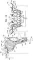


Classifications
-
- A—HUMAN NECESSITIES
- A61—MEDICAL OR VETERINARY SCIENCE; HYGIENE
- A61F—FILTERS IMPLANTABLE INTO BLOOD VESSELS; PROSTHESES; DEVICES PROVIDING PATENCY TO, OR PREVENTING COLLAPSING OF, TUBULAR STRUCTURES OF THE BODY, e.g. STENTS; ORTHOPAEDIC, NURSING OR CONTRACEPTIVE DEVICES; FOMENTATION; TREATMENT OR PROTECTION OF EYES OR EARS; BANDAGES, DRESSINGS OR ABSORBENT PADS; FIRST-AID KITS
- A61F2/00—Filters implantable into blood vessels; Prostheses, i.e. artificial substitutes or replacements for parts of the body; Appliances for connecting them with the body; Devices providing patency to, or preventing collapsing of, tubular structures of the body, e.g. stents
- A61F2/02—Prostheses implantable into the body
- A61F2/24—Heart valves ; Vascular valves, e.g. venous valves; Heart implants, e.g. passive devices for improving the function of the native valve or the heart muscle; Transmyocardial revascularisation [TMR] devices; Valves implantable in the body
- A61F2/2412—Heart valves ; Vascular valves, e.g. venous valves; Heart implants, e.g. passive devices for improving the function of the native valve or the heart muscle; Transmyocardial revascularisation [TMR] devices; Valves implantable in the body with soft flexible valve members, e.g. tissue valves shaped like natural valves
- A61F2/2418—Scaffolds therefor, e.g. support stents
-
- A—HUMAN NECESSITIES
- A61—MEDICAL OR VETERINARY SCIENCE; HYGIENE
- A61F—FILTERS IMPLANTABLE INTO BLOOD VESSELS; PROSTHESES; DEVICES PROVIDING PATENCY TO, OR PREVENTING COLLAPSING OF, TUBULAR STRUCTURES OF THE BODY, e.g. STENTS; ORTHOPAEDIC, NURSING OR CONTRACEPTIVE DEVICES; FOMENTATION; TREATMENT OR PROTECTION OF EYES OR EARS; BANDAGES, DRESSINGS OR ABSORBENT PADS; FIRST-AID KITS
- A61F2/00—Filters implantable into blood vessels; Prostheses, i.e. artificial substitutes or replacements for parts of the body; Appliances for connecting them with the body; Devices providing patency to, or preventing collapsing of, tubular structures of the body, e.g. stents
- A61F2/02—Prostheses implantable into the body
- A61F2/24—Heart valves ; Vascular valves, e.g. venous valves; Heart implants, e.g. passive devices for improving the function of the native valve or the heart muscle; Transmyocardial revascularisation [TMR] devices; Valves implantable in the body
- A61F2/2412—Heart valves ; Vascular valves, e.g. venous valves; Heart implants, e.g. passive devices for improving the function of the native valve or the heart muscle; Transmyocardial revascularisation [TMR] devices; Valves implantable in the body with soft flexible valve members, e.g. tissue valves shaped like natural valves
-
- A—HUMAN NECESSITIES
- A61—MEDICAL OR VETERINARY SCIENCE; HYGIENE
- A61F—FILTERS IMPLANTABLE INTO BLOOD VESSELS; PROSTHESES; DEVICES PROVIDING PATENCY TO, OR PREVENTING COLLAPSING OF, TUBULAR STRUCTURES OF THE BODY, e.g. STENTS; ORTHOPAEDIC, NURSING OR CONTRACEPTIVE DEVICES; FOMENTATION; TREATMENT OR PROTECTION OF EYES OR EARS; BANDAGES, DRESSINGS OR ABSORBENT PADS; FIRST-AID KITS
- A61F2/00—Filters implantable into blood vessels; Prostheses, i.e. artificial substitutes or replacements for parts of the body; Appliances for connecting them with the body; Devices providing patency to, or preventing collapsing of, tubular structures of the body, e.g. stents
- A61F2/02—Prostheses implantable into the body
- A61F2/24—Heart valves ; Vascular valves, e.g. venous valves; Heart implants, e.g. passive devices for improving the function of the native valve or the heart muscle; Transmyocardial revascularisation [TMR] devices; Valves implantable in the body
- A61F2/2412—Heart valves ; Vascular valves, e.g. venous valves; Heart implants, e.g. passive devices for improving the function of the native valve or the heart muscle; Transmyocardial revascularisation [TMR] devices; Valves implantable in the body with soft flexible valve members, e.g. tissue valves shaped like natural valves
- A61F2/2415—Manufacturing methods
-
- B—PERFORMING OPERATIONS; TRANSPORTING
- B23—MACHINE TOOLS; METAL-WORKING NOT OTHERWISE PROVIDED FOR
- B23P—METAL-WORKING NOT OTHERWISE PROVIDED FOR; COMBINED OPERATIONS; UNIVERSAL MACHINE TOOLS
- B23P15/00—Making specific metal objects by operations not covered by a single other subclass or a group in this subclass
- B23P15/001—Making specific metal objects by operations not covered by a single other subclass or a group in this subclass valves or valve housings
-
- A—HUMAN NECESSITIES
- A61—MEDICAL OR VETERINARY SCIENCE; HYGIENE
- A61F—FILTERS IMPLANTABLE INTO BLOOD VESSELS; PROSTHESES; DEVICES PROVIDING PATENCY TO, OR PREVENTING COLLAPSING OF, TUBULAR STRUCTURES OF THE BODY, e.g. STENTS; ORTHOPAEDIC, NURSING OR CONTRACEPTIVE DEVICES; FOMENTATION; TREATMENT OR PROTECTION OF EYES OR EARS; BANDAGES, DRESSINGS OR ABSORBENT PADS; FIRST-AID KITS
- A61F2/00—Filters implantable into blood vessels; Prostheses, i.e. artificial substitutes or replacements for parts of the body; Appliances for connecting them with the body; Devices providing patency to, or preventing collapsing of, tubular structures of the body, e.g. stents
- A61F2/02—Prostheses implantable into the body
- A61F2/24—Heart valves ; Vascular valves, e.g. venous valves; Heart implants, e.g. passive devices for improving the function of the native valve or the heart muscle; Transmyocardial revascularisation [TMR] devices; Valves implantable in the body
- A61F2/2427—Devices for manipulating or deploying heart valves during implantation
- A61F2/2436—Deployment by retracting a sheath
-
- A—HUMAN NECESSITIES
- A61—MEDICAL OR VETERINARY SCIENCE; HYGIENE
- A61F—FILTERS IMPLANTABLE INTO BLOOD VESSELS; PROSTHESES; DEVICES PROVIDING PATENCY TO, OR PREVENTING COLLAPSING OF, TUBULAR STRUCTURES OF THE BODY, e.g. STENTS; ORTHOPAEDIC, NURSING OR CONTRACEPTIVE DEVICES; FOMENTATION; TREATMENT OR PROTECTION OF EYES OR EARS; BANDAGES, DRESSINGS OR ABSORBENT PADS; FIRST-AID KITS
- A61F2210/00—Particular material properties of prostheses classified in groups A61F2/00 - A61F2/26 or A61F2/82 or A61F9/00 or A61F11/00 or subgroups thereof
- A61F2210/0014—Particular material properties of prostheses classified in groups A61F2/00 - A61F2/26 or A61F2/82 or A61F9/00 or A61F11/00 or subgroups thereof using shape memory or superelastic materials, e.g. nitinol
-
- A—HUMAN NECESSITIES
- A61—MEDICAL OR VETERINARY SCIENCE; HYGIENE
- A61F—FILTERS IMPLANTABLE INTO BLOOD VESSELS; PROSTHESES; DEVICES PROVIDING PATENCY TO, OR PREVENTING COLLAPSING OF, TUBULAR STRUCTURES OF THE BODY, e.g. STENTS; ORTHOPAEDIC, NURSING OR CONTRACEPTIVE DEVICES; FOMENTATION; TREATMENT OR PROTECTION OF EYES OR EARS; BANDAGES, DRESSINGS OR ABSORBENT PADS; FIRST-AID KITS
- A61F2220/00—Fixations or connections for prostheses classified in groups A61F2/00 - A61F2/26 or A61F2/82 or A61F9/00 or A61F11/00 or subgroups thereof
- A61F2220/0025—Connections or couplings between prosthetic parts, e.g. between modular parts; Connecting elements
-
- A—HUMAN NECESSITIES
- A61—MEDICAL OR VETERINARY SCIENCE; HYGIENE
- A61F—FILTERS IMPLANTABLE INTO BLOOD VESSELS; PROSTHESES; DEVICES PROVIDING PATENCY TO, OR PREVENTING COLLAPSING OF, TUBULAR STRUCTURES OF THE BODY, e.g. STENTS; ORTHOPAEDIC, NURSING OR CONTRACEPTIVE DEVICES; FOMENTATION; TREATMENT OR PROTECTION OF EYES OR EARS; BANDAGES, DRESSINGS OR ABSORBENT PADS; FIRST-AID KITS
- A61F2220/00—Fixations or connections for prostheses classified in groups A61F2/00 - A61F2/26 or A61F2/82 or A61F9/00 or A61F11/00 or subgroups thereof
- A61F2220/0025—Connections or couplings between prosthetic parts, e.g. between modular parts; Connecting elements
- A61F2220/0075—Connections or couplings between prosthetic parts, e.g. between modular parts; Connecting elements sutured, ligatured or stitched, retained or tied with a rope, string, thread, wire or cable
-
- A—HUMAN NECESSITIES
- A61—MEDICAL OR VETERINARY SCIENCE; HYGIENE
- A61F—FILTERS IMPLANTABLE INTO BLOOD VESSELS; PROSTHESES; DEVICES PROVIDING PATENCY TO, OR PREVENTING COLLAPSING OF, TUBULAR STRUCTURES OF THE BODY, e.g. STENTS; ORTHOPAEDIC, NURSING OR CONTRACEPTIVE DEVICES; FOMENTATION; TREATMENT OR PROTECTION OF EYES OR EARS; BANDAGES, DRESSINGS OR ABSORBENT PADS; FIRST-AID KITS
- A61F2230/00—Geometry of prostheses classified in groups A61F2/00 - A61F2/26 or A61F2/82 or A61F9/00 or A61F11/00 or subgroups thereof
- A61F2230/0063—Three-dimensional shapes
- A61F2230/0069—Three-dimensional shapes cylindrical
-
- A—HUMAN NECESSITIES
- A61—MEDICAL OR VETERINARY SCIENCE; HYGIENE
- A61F—FILTERS IMPLANTABLE INTO BLOOD VESSELS; PROSTHESES; DEVICES PROVIDING PATENCY TO, OR PREVENTING COLLAPSING OF, TUBULAR STRUCTURES OF THE BODY, e.g. STENTS; ORTHOPAEDIC, NURSING OR CONTRACEPTIVE DEVICES; FOMENTATION; TREATMENT OR PROTECTION OF EYES OR EARS; BANDAGES, DRESSINGS OR ABSORBENT PADS; FIRST-AID KITS
- A61F2230/00—Geometry of prostheses classified in groups A61F2/00 - A61F2/26 or A61F2/82 or A61F9/00 or A61F11/00 or subgroups thereof
- A61F2230/0063—Three-dimensional shapes
- A61F2230/0093—Umbrella-shaped, e.g. mushroom-shaped
-
- A—HUMAN NECESSITIES
- A61—MEDICAL OR VETERINARY SCIENCE; HYGIENE
- A61F—FILTERS IMPLANTABLE INTO BLOOD VESSELS; PROSTHESES; DEVICES PROVIDING PATENCY TO, OR PREVENTING COLLAPSING OF, TUBULAR STRUCTURES OF THE BODY, e.g. STENTS; ORTHOPAEDIC, NURSING OR CONTRACEPTIVE DEVICES; FOMENTATION; TREATMENT OR PROTECTION OF EYES OR EARS; BANDAGES, DRESSINGS OR ABSORBENT PADS; FIRST-AID KITS
- A61F2240/00—Manufacturing or designing of prostheses classified in groups A61F2/00 - A61F2/26 or A61F2/82 or A61F9/00 or A61F11/00 or subgroups thereof
- A61F2240/001—Designing or manufacturing processes
-
- A—HUMAN NECESSITIES
- A61—MEDICAL OR VETERINARY SCIENCE; HYGIENE
- A61F—FILTERS IMPLANTABLE INTO BLOOD VESSELS; PROSTHESES; DEVICES PROVIDING PATENCY TO, OR PREVENTING COLLAPSING OF, TUBULAR STRUCTURES OF THE BODY, e.g. STENTS; ORTHOPAEDIC, NURSING OR CONTRACEPTIVE DEVICES; FOMENTATION; TREATMENT OR PROTECTION OF EYES OR EARS; BANDAGES, DRESSINGS OR ABSORBENT PADS; FIRST-AID KITS
- A61F2250/00—Special features of prostheses classified in groups A61F2/00 - A61F2/26 or A61F2/82 or A61F9/00 or A61F11/00 or subgroups thereof
- A61F2250/0014—Special features of prostheses classified in groups A61F2/00 - A61F2/26 or A61F2/82 or A61F9/00 or A61F11/00 or subgroups thereof having different values of a given property or geometrical feature, e.g. mechanical property or material property, at different locations within the same prosthesis
- A61F2250/0039—Special features of prostheses classified in groups A61F2/00 - A61F2/26 or A61F2/82 or A61F9/00 or A61F11/00 or subgroups thereof having different values of a given property or geometrical feature, e.g. mechanical property or material property, at different locations within the same prosthesis differing in diameter
-
- A—HUMAN NECESSITIES
- A61—MEDICAL OR VETERINARY SCIENCE; HYGIENE
- A61F—FILTERS IMPLANTABLE INTO BLOOD VESSELS; PROSTHESES; DEVICES PROVIDING PATENCY TO, OR PREVENTING COLLAPSING OF, TUBULAR STRUCTURES OF THE BODY, e.g. STENTS; ORTHOPAEDIC, NURSING OR CONTRACEPTIVE DEVICES; FOMENTATION; TREATMENT OR PROTECTION OF EYES OR EARS; BANDAGES, DRESSINGS OR ABSORBENT PADS; FIRST-AID KITS
- A61F2250/00—Special features of prostheses classified in groups A61F2/00 - A61F2/26 or A61F2/82 or A61F9/00 or A61F11/00 or subgroups thereof
- A61F2250/0058—Additional features; Implant or prostheses properties not otherwise provided for
- A61F2250/006—Additional features; Implant or prostheses properties not otherwise provided for modular
- A61F2250/0063—Nested prosthetic parts
Definitions
- Some applications of the present invention relate in general to valve replacement. More specifically, some applications of the present invention relate to prosthetic valves for replacement of a cardiac valve.
- Ischemic heart disease causes regurgitation of a heart valve by the combination of ischemic dysfunction of the papillary muscles, and the dilatation of the ventricle that is present in ischemic heart disease, with the subsequent displacement of the papillary muscles and the dilatation of the valve annulus.
- Dilation of the annulus of the valve prevents the valve leaflets from fully coapting when the valve is closed. Regurgitation of blood from the ventricle into the atrium results in increased total stroke volume and decreased cardiac output, and ultimate weakening of the ventricle secondary to a volume overload and a pressure overload of the atrium.
- WO 2013/072496 A1 discloses an implant comprising a tubular frame, a plurality of distal arms capable of pressing against a first face of a tissue, and a plurality of proximal arms having an end linked to the frame and a free end intended to press against a second face of the tissue in order to clamp the tissue.
- the implant comprises a first integral assembly comprising a first portion of the frame and the proximal arms, and a second integral assembly comprising a second portion of the frame and the distal arms, the first assembly and the second assembly being mounted one on top of the other.
- the first portion of the frame has the shape of a proximal sleeve extending longitudinally between a proximal end and a distal end of the sleeve.
- the linked end of each proximal arm is linked to the distal end of the proximal sleeve, and the free end of each proximal arm extends beyond said distal end of the proximal sle
- the present invention relates to apparatus for use with a heart of a subject, the apparatus comprising: an inner stent frame that:
- an implant having a tubular portion, an upstream support portion and one or more flanges.
- the implant is assembled from two concentric frames.
- An inner frame defines the tubular portion and the upstream support portion, and an outer frame defines the flanges.
- the implant is percutaneously deliverable to a native heart valve in a compressed state, and is expandable at the native valve.
- the implant is secured at a native heart valve by sandwiching tissue of the native valve between the upstream support portion and the flanges.
- the outer frame is radially thicker than the inner frame.
- the outer frame is undersized with respect to the inner frame, such that it constrains the inner frame even in a relaxed expanded state of the implant, and such that even in the relaxed expanded state residual stress is present in one or both of the frames.
- a toroidal space is defined by the tubular portion, the upstream support portion, and the flanges.
- the implant is configured such that the toroidal space is dimensioned proportionally to dimensions of the tubular portion.
- apparatus for use with a prosthetic valve including a connector, the connector including a flexible sheet that is folded to define:
- the panel has an edge between the first side and the second side, and each flap is foldable over the edge, so as to be disposed on the second side of the panel.
- the plurality of flaps is arranged in a circuit such that each flap has two adjacent flaps around the circuit, and the fold axis of each flap is oriented at 60-120 degrees from the fold axis of each of its adjacent flaps.
- the flexible sheet is a single unitary flexible sheet, and the unitary flexible sheet is folded to define the panel, the leaflet receptacle, and the plurality of flaps.
- the plurality of flaps includes exactly four flaps.
- first row of first-tab stitching holes and the second row of first-tab stitching holes diverge at 10-45 degrees from each other, and the first row of second-tab stitching holes and the second row of second-tab stitching holes diverge at 10-45 degrees from each other.
- first row of first-tab stitching holes and the second row of first-tab stitching holes diverge at 10-30 degrees from each other, and the first row of second-tab stitching holes and the second row of second-tab stitching holes diverge at 10-30 degrees from each other.
- first row of first-tab stitching holes and the second row of first-tab stitching holes diverge at 15-25 degrees from each other, and the first row of second-tab stitching holes and the second row of second-tab stitching holes diverge at 15-25 degrees from each other.
- each of the first leaflet-engaging tab and the second leaflet-engaging tab includes (i) an outer layer, and (ii) an inner layer that is positioned to be sandwiched between the outer layer and the one or more leaflets, and:
- the apparatus further includes:
- the leaflets define an upstream end and a downstream end of the lumen by being arranged and coupled to the frame so as to facilitate one-way fluid flow through the lumen.
- the first leaflet has a first-leaflet downstream edge
- the second leaflet has a second-leaflet downstream edge
- each of the first and second leaflet-engaging tabs extends in a downstream direction beyond the first-leaflet downstream edge and the second-leaflet downstream edge.
- first cushion and the second cushion are disposed further downstream than the first-leaflet downstream edge and the second-leaflet downstream edge.
- the first and second cushions are each defined by folds in the flexible sheet.
- first and second rows of first-tab stitching holes diverge from each other such that progressively downstream parts of the first and second rows of first-tab stitching holes are progressively further from each other, and the first and second rows of second-tab stitching holes diverge from each other such that progressively downstream parts of the first and second rows of second-tab stitching holes are progressively further from each other.
- first and second rows of first-tab stitching holes diverge at 10-45 degrees from each other, and the first and second rows of second-tab stitching holes diverge at 10-45 degrees from each other.
- the fold axis of each flap is oriented at 70-110 degrees from the fold axis of each of its adjacent flaps.
- the fold axis of each flap is oriented at 80-100 degrees from the fold axis of each of its adjacent flaps.
- the connector has a folded state in which the sheet is folded to define the panel, the leaflet receptacle, and the plurality of flaps, and the sheet further has an unfolded state in which the sheet defines a plane, and further defines, in the plane:
- a first flap part of each of the flaps is disposed on the first side of the panel, and each of the flaps is folded around the panel such that a second flap part of each of the flaps is disposed on the second side of the panel.
- the sheet further defines a first bridging element via which the first tab portion is connected to the panel, and a second bridging element via which the second tab portion is connected to the panel.
- the first and second bridging elements extend from respective edges of the panel and toward each other across the first side of the panel, and each of the first and second tab portions protrudes from the respective bridging element in the first direction away from the first side of the panel.
- the flaps are connected to the panel independently of the bridging elements.
- the flaps are connected to the panel via the bridging elements.
- the bridging elements are disposed on the first side of the panel, and each flap extends from one of the bridging elements and around the panel such that a flap part of each flap is disposed on the second side of the panel.
- the first tab portion and the second tab portion flank the panel by being disposed, in the plane, on opposing lateral sides of the panel.
- the first and second tab portions, the first and second bridging elements, and the panel are arranged in a row that defines a lateral axis in the plane, and the fold axis of each of the flaps is at 30-60 degrees from the lateral axis.
- apparatus for use with a prosthetic valve including a connector, the connector comping:
- the panel substantially defines a plane, and each flap is configured to fold, over its respective fold axis, out of the plane.
- each flap is configured to fold over a respective portion of the second side of the panel.
- the connector consists of a single unitary sheet of a material that is folded to define the panel, the leaflet-engaging tab, and the plurality of flaps.
- the plurality of flaps includes exactly four flaps.
- the fold axis of each flap is oriented at 70-110 degrees from the fold axes of its adjacent flaps.
- the fold axis of each flap is oriented at 80-100 degrees from the fold axes of its adjacent flaps.
- the fold axis of each flap is oriented at approximately 90 degrees from the fold axes of its adjacent flaps.
- apparatus for use at a heart valve of a subject including:
- the first-tube wall thickness is 0.45-0.65 mm
- the second-tube wall thickness is 0.6-0.8 mm.
- the second-tube wall thickness is at least 20 percent greater than the first-tube wall thickness.
- the second-tube wall thickness is at least 30 percent greater than the first-tube wall thickness.
- apparatus for use with a heart of a subject including:
- the outer frame is coupled to the inner frame such that:
- the outer-frame coupling elements are welded to the inner-frame coupling elements.
- the apparatus at each commissure the apparatus includes a fabric connector to which the commissural portions of the two leaflets are secured, and the plurality of stitches secures the commissural portions of the two leaflets to the inner stent frame and the outer stent frame by being attached to the fabric connector.
- the fabric connector is shaped to define (i) a panel having a first side and a second side, (ii) one or more leaflet-engaging tabs to which the commissural portions of the two leaflets are stitched, the tabs protruding from the first side of the panel, and (iii) a plurality of flaps, wrapped around elements of the inner stent frame and elements of the outer stent frame, and secured thus by stitching.
- apparatus for use in a heart of a subject including:
- the frame assembly is dimensioned such that the cross-sectional area of the toroidal space is 5-8 percent of the transverse cross-sectional area of the tubular portion.
- the frame assembly is dimensioned such that the cross-sectional area of the toroidal space is 6-7 percent of the transverse cross-sectional area of the tubular portion.
- the frame assembly is dimensioned such that the cross-sectional area of the toroidal space is 6.5-7.5 percent of the transverse cross-sectional area of the tubular portion.
- the upstream support portion includes a plurality of arms that, in the expanded state of the frame assembly, protrude radially outward from the tubular portion.
- the frame assembly defines the toroidal space between the flanges, the tubular portion, and the arch portions of the arms of the upstream support portion.
- each flange extends radially outward from the tubular portion and toward a tip of the flange, and the arch portion of the arms curves in a downstream direction past the tips of the flanges.
- apparatus for use at a heart valve of a subject including:
- apparatus for use with a native valve that is disposed between an atrium and a ventricle of a heart of a subject including:
- valve frame is cut from a first tube of nitinol that has a first-tube wall thickness
- outer frame is cut from a second tube of nitinol that has a second-tube wall thickness that is greater than the first-tube wall thickness
- the expanded state of the tubular portion is a constrained expanded state
- the fixation of the outer-frame coupling elements to the valve-frame coupling elements is such that, in a relaxed expanded state of the apparatus, the outer frame constrains the tubular portion in the constrained expanded state.
- the apparatus further includes an upstream support portion that includes a plurality of arms coupled to the tubular portion, and:
- the ring circumscribes the tubular portion.
- valve-frame coupling elements are disposed circumferentially around the longitudinal axis between the upstream end and the downstream end but not at the upstream end nor at the downstream end.
- the upstream support portion includes one or more fabric pockets disposed circumferentially, each pocket of the one or more pockets having an opening that faces a downstream direction.
- the outer frame is coupled to the valve frame only via the fixation of the outer-frame coupling elements to the respective valve-frame coupling elements.
- the apparatus further includes an upstream support portion that includes a plurality of arms that extend radially from the tubular portion, and:
- the tool is operable from outside the subject to transition the implant from its compressed state into the intermediate state by (i) releasing the legs into their released-flange state, while retaining the tubular portion in its compressed state, and (ii) subsequently, releasing the upstream support portion into its released-arm state, while retaining the tubular portion in its compressed state.
- the tool is operable from outside the subject to transition the implant from its compressed state into the intermediate state by (i) releasing the upstream support portion into its released-arm state, while retaining the tubular portion in its compressed state, and (ii) subsequently, releasing the legs into their released-flange state, while retaining the tubular portion in its compressed state.
- the fixation of the outer-frame coupling elements to the valve-frame coupling elements is such that, when the apparatus is in its intermediate state, expansion of the tubular portion from its compressed state toward its expanded state moves the flanges longitudinally away from the valve-frame coupling elements.
- the fixation of the outer-frame coupling elements to the valve-frame coupling elements is such that, when the apparatus is in its intermediate state, expansion of the tubular portion from its compressed state toward its expanded state reduces the amplitude of the pattern of the ring and passes the flanges between the arms.
- the upstream support portion further includes a covering that covers the arms to form an annular shape in the released-arm state, and, when the apparatus is in its intermediate state, expansion of the tubular portion from its compressed state toward its expanded state presses the flanges onto the covering.
- a downstream end of each leg is longitudinally closer than the valve-frame coupling elements to the downstream end, and the flange of each leg is disposed longitudinally closer than the valve-frame coupling elements to the upstream end.
- each leg in the expanded state of the tubular portion, is longitudinally closer than the valve-frame coupling elements to the downstream end, and the flange of each leg is disposed longitudinally closer than the valve-frame coupling elements to the upstream end.
- apparatus for use with a native valve of a heart of a subject including an implant that includes:
- valve frame is cut from a first tube of nitinol that has a first-tube wall thickness
- outer frame is cut from a second tube of nitinol that has a second-tube wall thickness that is greater than the first-tube wall thickness
- tubular portion, the upstream support portion, and the outer frame are arranged such that the longitudinal distance is more than 20 percent greater than the length-decrease amount.
- tubular portion, the upstream support portion, and the outer frame are arranged such that the longitudinal distance is more than 30 percent greater than the length-decrease amount.
- tubular portion, the upstream support portion, and the outer frame are arranged such that the longitudinal distance is more than 40 percent greater than the length-decrease amount.
- apparatus for use with a native valve that is disposed between an atrium and a ventricle of a heart of a subject including:
- valve frame is cut from a first tube of nitinol that has a first-tube wall thickness
- outer frame is cut from a second tube of nitinol that has a second-tube wall thickness that is greater than the first-tube wall thickness
- the expanded state of the tubular portion is a constrained expanded state
- the fixation of the peaks to the respective sites of the tubular portion is such that, in a relaxed expanded state of the apparatus, the outer frame constrains the tubular portion in the constrained expanded state.
- the outer frame is coupled to the valve frame only via the fixation of the peaks to the respective sites of the tubular portion at the respective coupling points.
- apparatus for use with a native valve that is disposed between an atrium and a ventricle of a heart of a subject including:
- valve frame is cut from a first tube of nitinol that has a first-tube wall thickness
- outer frame is cut from a second tube of nitinol that has a second-tube wall thickness that is greater than the first-tube wall thickness
- the outer frame is coupled to the valve frame only via the fixation of the outer-frame coupling elements to the respective valve-frame coupling elements.
- apparatus for use with a native valve that is disposed between an atrium and a ventricle of a heart of a subject including:
- valve frame is cut from a first tube of nitinol that has a first-tube wall thickness
- outer frame is cut from a second tube of nitinol that has a second-tube wall thickness that is greater than the first-tube wall thickness
- the outer frame is coupled to the valve frame only via the fixation of the peaks to the respective sites of the tubular portion at the respective coupling points.
- apparatus for use with a native valve disposed between an atrium and a ventricle of a heart of a subject including:
- valve frame is cut from a first tube of nitinol that has a first-tube wall thickness
- outer frame is cut from a second tube of nitinol that has a second-tube wall thickness that is greater than the first-tube wall thickness
- the outer frame is coupled to the valve frame only via the fixation of the outer-frame coupling elements to the respective valve-frame coupling elements.
- apparatus for use with a native valve disposed between an atrium and a ventricle of a heart of a subject including:
- valve frame is cut from a first tube of nitinol that has a first-tube wall thickness
- outer frame is cut from a second tube of nitinol that has a second-tube wall thickness that is greater than the first-tube wall thickness
- the outer frame is coupled to the valve frame only via the fixation of the peaks to the respective sites of the tubular portion at the respective coupling points.
- apparatus for use with a native valve of a heart of a subject including:
- valve frame is cut from a first tube of nitinol that has a first-tube wall thickness
- at least one leg is cut from a second tube of nitinol that has a second-tube wall thickness that is greater than the first-tube wall thickness
- the frame assembly is configured such that increasing the diameter of the tubular portion by expanding the frame assembly toward the expanded state causes longitudinal movement of the upstream end of the tubular portion toward the coupling point.
- the coupling point is disposed closer to the downstream end of the frame assembly than are either the tissue-engaging flange or the upstream support portion.
- the leg in the expanded state of the frame assembly, the leg extends away from the central longitudinal axis.
- the frame assembly is configured such that the longitudinal movement of the tissue-engaging flange away from the coupling point is a translational movement of the tissue-engaging flange that does not include rotation of the tissue-engaging flange.
- the frame assembly is configured such that increasing the diameter of the tubular portion by expanding the frame assembly toward the expanded state causes 1-20 mm of longitudinal movement of the tissue-engaging flange away from the coupling point.
- the frame assembly is configured such that increasing the diameter of the tubular portion by expanding the frame assembly toward the expanded state causes 1-20 mm of longitudinal movement of the upstream support portion toward the coupling point.
- the frame assembly is configured such that increasing the diameter of the tubular portion by expanding the frame assembly toward the expanded state reduces a distance between the upstream support portion and the tissue-engaging flange by 5-30 mm.
- the frame assembly is configured such that increasing the diameter of the tubular portion by expanding the frame assembly toward the expanded state moves the tissue-engaging flange longitudinally past the upstream support portion.
- the leg is disposed on an outside of the tubular portion.
- the plurality of coupling points is disposed circumferentially around the frame assembly on a transverse plane that is orthogonal to the longitudinal axis of the frame assembly.
- the plurality of legs is coupled to the valve frame via a plurality of struts, each strut:
- the leg frame is structured such that each leg of the plurality of legs is coupled to two struts of the plurality of struts, and two struts of the plurality of struts are coupled to each coupling point of the plurality of coupling points.
- the leg is coupled to the valve frame via a strut, the strut:
- the at least one leg includes at least a first leg and a second leg.
- first leg and the second leg are both coupled to the valve frame at the coupling point.
- the first leg is coupled to the coupling point via a respective first strut
- the second leg is coupled to the coupling point via a respective second strut
- first and second legs, the first and second struts, and the coupling point are arranged such that, in the expanded state of the frame assembly:
- the coupling point includes at least a first coupling point and a second coupling point.
- the leg is coupled to the valve frame at the first coupling point and at the second coupling point.
- the leg is coupled to the first coupling point via a respective first strut, and to the second coupling point via a respective second strut.
- first and second legs, the first and second struts, and the coupling point are arranged such that, in the expanded state of the frame assembly:
- the upstream support portion extends radially outward from the tubular portion.
- the upstream support portion in the compressed state of the frame assembly, is generally tubular, collinear with the tubular portion, and disposed around the central longitudinal axis.
- an inner region of the upstream support portion extends radially outward from the tubular portion at a first angle with respect to the tubular portion, and an outer region of the upstream support portion extends, from the inner region of the upstream support portion, further radially outward from the tubular portion at a second angle with respect to the tubular portion, the second angle being smaller than the first angle.
- apparatus for use with a native valve of a heart of a subject including:
- valve frame is cut from a first tube of nitinol that has a first-tube wall thickness
- at least one leg is cut from a second tube of nitinol that has a second-tube wall thickness that is greater than the first-tube wall thickness
- apparatus for use with a native valve of a heart of a subject including:
- valve frame is cut from a first tube of nitinol that has a first-tube wall thickness
- at least one leg is cut from a second tube of nitinol that has a second-tube wall thickness that is greater than the first-tube wall thickness
- apparatus for use with a native valve of a heart of a subject including:
- the inner frame is cut from a first tube of nitinol that has a first-tube wall thickness
- the outer frame is cut from a second tube of nitinol that has a second-tube wall thickness that is greater than the first-tube wall thickness
- apparatus for use with a native valve disposed between an atrium and a ventricle of a heart of a subject including:
- each pocket is shaped and arranged to billow in response to perivalvular flow of blood in an upstream direction.
- the apparatus is configured to be transluminally delivered to the heart, and implanted at the native valve by expansion of the apparatus, such that the upstream support portion is disposed in the atrium and the tubular portion extends from the upstream support portion into the ventricle, and each pocket is shaped and arranged such that perivalvular flow of blood in an upstream direction presses the pocket against tissue of the atrium.
- apparatus including:
- the tubular portion is cut from a first tube of nitinol that has a first-tube wall thickness
- the outer frame is cut from a second tube of nitinol that has a second-tube wall thickness that is greater than the first-tube wall thickness
- each hub has six radiating spokes, two of the six spokes being part of a first cell of the two adjacent cells, two of the six spokes being part of a second cell of the two adjacent cells, one of the six spokes being the arm, and one of the six spokes being the second end of the appendage.
- the appendages are in-plane with the tubular portion.
- the appendages are in-plane with the outer frame.
- Implant 20 comprises a frame assembly 22 that has an upstream end 24, a downstream end 26, and a central longitudinal axis ax1 therebetween.
- Frame assembly 22 comprises a valve frame 30 that comprises a tubular portion 32 that has an upstream end 34 and a downstream end 36, and is shaped to define a lumen 38 through the tubular portion from the upstream end to the downstream end.
- Tubular portion 32 circumscribes axis ax1, and thereby defines lumen 38 along the axis.
- Valve frame 30 further comprises an upstream support portion 40, extending from upstream end 34 of tubular portion 32.
- Frame assembly 22 further comprises at least one leg 50, coupled to valve frame 30 at (e.g., via) a coupling point 52, and having a tissue-engaging flange 54.
- leg 50 is part of an outer frame (or “leg frame") 60, and frames 30 and 60 define respective coupling elements 31 and 61, which are fixed with respect to each other at coupling points 52.
- frames 30 and 60 are coupled to each other only at coupling points 52 (e.g., only via the fixation of coupling elements 31 and 61 with respect to each other).
- Implant 20 further comprises a valve member 58 (e.g., one or more prosthetic leaflets) disposed within lumen 38, and configured to facilitate one-way liquid flow through the lumen from upstream end 34 to downstream end 36 (e.g., thereby defining the orientation of the upstream and downstream ends of tubular portion 32).
- a valve member 58 e.g., one or more prosthetic leaflets
- Fig. 1A shows implant 20 in a fully-expanded state, in which frame assembly 22 is in a fully-expanded state.
- Fig. 1B shows an exploded view of frame assembly 22 in its fully-expanded state.
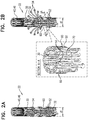
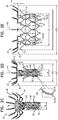
- Figs. 2A-E show respective states of implant 20, which will be discussed in more detail hereinbelow with respect to the implantation of the implant and the anatomy in which the implant is implanted.
- Fig. 1A shows implant 20 in a fully-expanded state, in which frame assembly 22 is in a fully-expanded state.
- FIG. 2A shows implant 20 in a compressed state (in which frame assembly 22 is in a compressed state), for percutaneous delivery of the implant to the heart of the subject.
- leg 50 including flange 54 thereof
- upstream support portion 40 is generally tubular, collinear with tubular portion 32 (e.g., extending collinearly from the tubular portion), and disposed around axis ax1.
- Fig. 2B shows a state of implant 20 in which tissue-engaging flange 54 of each leg 50 extends radially away from axis ax1 (e.g., radially away from tubular portion 32).
- Fig. 2C shows a state of implant 20 in which upstream-support portion 40 extends radially away from axis ax1 (and thereby radially away from tubular portion 32).
- Fig. 2D shows a state of implant 20 in which both flange 54 and portion 40 extend away from axis ax1. In the fully-expanded state ( Figs. 1A-B ) both upstream support portion 40 and flange 54 extend radially away from axis ax1.
- frame assembly 22 is biased (e.g., shape-set) to assume its fully-expanded state, which is shown in Fig. 2E .
- Transitioning of implant 20 between the respective states is typically controlled by delivery apparatus, such as by constraining the implant in a compressed state within a delivery tube and/or against a control rod, and selectively releasing portions of the implant to allow them to expand.
- tubular portion 32 In the compressed state of frame assembly 22, tubular portion 32 has a diameter d1, and in the expanded state, the tubular portion has a diameter d2 that is greater that diameter d1.
- diameter d1 is 4-15 mm, (e.g., 5-11 mm) and diameter d2 is 20-50 mm, (e.g., 23-33 mm).
- tubular portion 32 bulges slightly in its middle (e.g., is slightly barrel-shaped).
- values of diameter d2 are the average diameter along the tubular portion.
- values for the cross-sectional area of the tubular portion are the average cross-sectional area along the tubular portion. This also applies to other implants described herein, mutatis mutandis.
- Frame assembly 22 is configured such that increasing the diameter of tubular portion 32 (e.g., from d1 to d2) causes longitudinal movement of flange 54 away from coupling point 52. In the same way, reducing the diameter of tubular portion 32 (e.g., from d2 to d1) causes longitudinal movement of flange 54 toward coupling point 52.
- longitudinal movement means movement parallel with central longitudinal axis ax1. Therefore, longitudinal movement of flange 54 away from coupling point 52 means increasing a distance, measured parallel with longitudinal axis ax1, between flange 54 and coupling point 52. An example of such a configuration is described in more detail with respect to Fig. 3A .
- expansion of tubular portion 32 from its compressed state toward its expanded state increases a circumferential distance between each of coupling points 52 and its adjacent coupling points (e.g., between each of outer-frame coupling elements 61 and its adjacent outer-frame coupling elements) (e.g., from d8 to d9), and (ii) moves legs 50 in a longitudinally upstream direction with respect to the tubular portion.
- frame assembly 22 is configured such that increasing the diameter of tubular portion 32 also causes longitudinal movement of upstream support portion 40 toward coupling point 52, e.g., as described in more detail with respect to Figs. 3B-C .
- frame assembly 22 is configured such that increasing the diameter of tubular portion 32 also causes longitudinal movement of upstream end 34 of tubular portion 32 toward coupling point 52. In the same way, reducing the diameter of tubular portion 32 causes longitudinal movement of upstream end 34 away from coupling point 52.
- upstream support portion 40 comprises a plurality of arms 46 that each extends radially outward from tubular portion 32 (e.g., from upstream end 34 of the tubular portion). Arms 46 are typically flexible. For some such applications, arms 46 are coupled to tubular portion 32 such that each arm may deflect independently of adjacent arms during implantation (e.g., due to anatomical topography).
- upstream support portion 40 comprises a plurality of barbs 48 that extend out of a downstream surface of the upstream support portion.
- each arm 46 may comprise one or more of barbs 48.
- Barbs 48 press into tissue upstream of the native valve (e.g., into the valve annulus), thereby inhibiting downstream movement of implant 20 (in addition to inhibition of downstream movement provided by the geometry of upstream support portion 40).
- covering 23 typically comprises a flexible sheet, such as a fabric, e.g., comprising polyester.
- covering 23 covers at least part of tubular portion 32, typically lining an inner surface of the tubular portion, and thereby defining lumen 38.
- upstream support portion 40 is covered with covering 23, e.g., extending between arms 46 to form an annular shape. It is hypothesized that this reduces a likelihood of paravalvular leakage. For such applications, excess covering 23 may be provided between arms 46 of upstream support portion 40, so as to facilitate their independent movement.
- Fig. 1A shows covering 23 covering an upstream side of upstream support portion 40
- the covering typically additionally (or alternatively) covers the downstream side of the upstream support portion.
- covering 23 may extend over the tips of arms 46 and down the outside of the arms, or a separate piece of covering may be provided on the downstream side of the upstream support portion.
- each arm 46 may be individually covered in a sleeve of covering 23, thereby facilitating independent movement of the arms.
- legs 50 e.g., flanges thereof
- covering 23 At least part of legs 50 (e.g., flanges thereof) is covered with covering 23.
- frame assembly 22 comprises a plurality of legs 50 (e.g., two or more legs, e.g., 2-16 legs, such as 4-12 legs, such as 6-12 legs), arranged circumferentially around valve frame 30 (e.g., around the outside of tubular portion 32).
- frame assembly 22 comprises a plurality of coupling points 52 at which the legs are coupled to valve frame 30.
- each leg 50 is typically coupled to a coupling point 52 via a strut 70.
- each leg 50 is coupled to a plurality of (e.g., two) coupling points 52 via a respective plurality of (e.g., two) struts 70.
- frame assembly 22 is arranged such that, in the expanded state of the frame assembly, leg 50 is disposed, circumferentially with respect to tubular portion 32, between two struts, and each of the two struts are disposed, circumferentially with respect to the tubular portion, between the leg and a respective coupling point 52.
- a plurality of (e.g., two) legs are coupled to each coupling point 52 via a respective plurality of (e.g., two) struts 70.
- frame assembly 22 is arranged such that, in the expanded state of the frame assembly, coupling point 52 is disposed, circumferentially with respect to tubular portion 32, between two struts 70, and each of the two struts are disposed, circumferentially with respect to the tubular portion, between the coupling point and a respective leg 50.
- frame assembly 22 comprises an outer frame (e.g., a leg frame) 60 that circumscribes tubular portion 32, comprises (or defines) the plurality of legs 50 and the plurality of struts 70, and is coupled to valve frame 30 at the plurality of coupling points 52, such that the plurality of legs are distributed circumferentially around the tubular portion.
- outer frame 60 comprises a ring 66 that is defined by a pattern of alternating peaks 64 and troughs 62, and that typically circumscribes tubular portion 32.
- the ring may comprise struts 70, extending between the peaks and troughs.
- Peaks 64 are longitudinally closer to upstream end 34 of tubular portion 32 than to downstream end 36, and troughs 62 are longitudinally closer to the downstream end than to the upstream end. (It is to be noted that throughout this patent application, including the specification and the claims, the term “longitudinally” means with respect to longitudinal axis ax1.
- peaks 64 are closer than troughs 62 to upstream end 34, and troughs 62 are closer than peaks 64 to downstream end 36.
- frame 60 comprises ring 66
- each leg 50 is coupled to the ring (or defined by frame 60) at a respective trough 62.
- the peaks and troughs are defined by ring 66 having a generally zig-zag shape.
- the scope of the invention includes ring 66 having another shape that defines peaks and troughs, such as a serpentine or sinusoid shape.
- the coupling points are disposed circumferentially around the frame assembly (e.g., around axis ax1), typically on a transverse plane that is orthogonal to axis ax1. This transverse plane is illustrated by the position of section A-A in Fig. 2B .
- coupling points 52 may be disposed at different longitudinal heights of frame assembly 22, e.g., such that different flanges 54 are positioned and/or moved differently to others.
- coupling points 52 (and therefore coupling elements 31 and 61) are disposed longitudinally between upstream end 24 and downstream end 26 of frame assembly 22, but not at either of these ends.
- coupling points 52 are disposed longitudinally between upstream end 34 and downstream end 36 of tubular portion 32, but not at either of these ends.
- the coupling points may be more than 3 mm (e.g., 4-10 mm) both from end 34 and from end 36. It is hypothesized that this advantageously positions the coupling points at a part of tubular portion 32 that is more rigid than end 34 or end 36.
- leg 50 is typically expandable into its expanded state (e.g., a released-flange state) such that flange 54 extends away from axis ax1, independently of increasing the diameter of tubular portion 32 (e.g., as shown in Figs. 2B & 2D ).
- upstream support portion 40 is typically expandable into its expanded state (e.g., a released-arm state) such that it (e.g., arms 46 thereof) extends away from axis ax1, independently of increasing the diameter of tubular portion 32 (e.g., as shown in Fig. 2C & 2D ).
- the state shown in Fig. 2D may be considered to be an intermediate state.
- implant 20 is typically configured such that legs 50 (e.g., flanges 54 thereof) and upstream support portion 40 are expandable such that they both extend away from axis ax1, while retaining a distance d3 therebetween. This distance is subsequently reducible to a distance d4 by expanding tubular portion 32 (e.g., shown in Fig. 2E ).
- flange 54 can extend away from axis ax1 over 40 percent (e.g., 40-80 percent, such as 40-70 percent) of the distance that it extends from the axis subsequent to the expansion of the tubular portion.
- a span d15 of the flanges while tubular portion 32 is in its compressed state may be at least 40 percent (e.g., 40-80 percent, such as 40-70 percent) as great as a span d16 of the flanges subsequent to the expansion of the tubular portion.
- span d15 is greater than 15 mm and/or less than 50 mm (e.g., 20-30 mm).
- span d16 is greater than 30 mm and/or less than 60 mm (e.g., 40-50 mm). It is to be noted that flange 54 is effectively fully expanded, with respect to other portions of leg 50 and/or with respect to tubular portion 32, before and after the expansion of the tubular portion.
- upstream support portion 40 (e.g., arms 46) can extend away from axis ax1 over 30 percent (e.g., 30-70 percent) of the distance that it extends from the axis subsequent to the expansion of the tubular portion. That is, for some applications, a span d17 of the upstream support portion while tubular portion 32 is in its compressed state may be at least 30 percent (e.g., 30-70 percent) as great as a span d18 of the upstream support portion subsequent to the expansion of the tubular portion.
- span d17 is greater than 16 mm (e.g., greater than 20 mm) and/or less than 50 mm (e.g., 30-40 mm).
- span d18 is greater than 40 mm and/or less than 65 mm (e.g., 45-56 mm, such as 45-50 mm). It is to be noted that upstream support portion 40 is effectively fully expanded, with respect to tubular portion 32, before and after the expansion of the tubular portion.
- flanges 54 typically translate radially outward from span d15 to span d16 (e.g., without deflecting).
- upstream support portion 40 behaves similarly (e.g., arms 46 translated radially outward from span d17 to span d18, e.g., without deflecting). That is, an orientation of each flange 54 and/or each arm 46 with respect to tubular portion 32 and/or axis ax1 is typically the same in the state shown in Fig. 2D as it is in the state shown in Fig. 2E . Similarly, for some applications an orientation of each flange 54 with respect to upstream support portion 40 (e.g., with respect to one or more arms 46 thereof) is the same before and after expansion of tubular portion 32.
- increasing the diameter of tubular portion 32 from d1 to d2 causes greater than 1 mm and/or less than 20 mm (e.g., 1-20 mm, such as 1-10 mm or 5-20 mm) of longitudinal movement of flange 54 away from coupling point 52.
- increasing the diameter of tubular portion 32 from d1 to d2 causes greater than 1 mm and/or less than 20 mm (e.g., 1-20 mm, such as 1-10 mm or 5-20 mm) of longitudinal movement of upstream support portion 40 toward coupling point 52.
- distance d3 is 7-30 mm.
- distance d4 is 0-15 mm (e.g., 2-15 mm).
- increasing the diameter of tubular portion 32 from d1 to d2 reduces the distance between the upstream support portion and flanges 54 by more than 5 mm and/or less than 30 mm, such as 5-30 mm (e.g., 10-30 mm, such as 10-20 mm or 20-30 mm).
- the difference between d3 and d4 is generally equal to the difference between d1 and d2.
- the difference between d3 and d4 is more than 1.2 and/or less than 3 times (e.g., 1.5-2.5 times, such as about 2 times) greater than the difference between d1 and d2.
- flanges 54 curve such that a tip of each flange is disposed at a shallower angle with respect to inner region 42 of upstream support portion 40, than are portions of leg 50 that are closer to downstream end 26 of frame assembly 22.
- a tip of each flange may be generally parallel with inner region 42.
- a tip portion 55 of each flange 54 that extends from the tip of the flange at least 2 mm along the flange, is disposed within 2 mm of upstream support portion 40.
- tubular portion 32 while tubular portion 32 is in its expanded state, for at least 5 percent (e.g., 5-8 percent, or at least 8 percent) of span 18 of upstream support portion 40, the upstream support portion is disposed within 2 mm of a flange 54.
- flanges 54 may pass between arms 46, and press directly against covering 23.) It is hypothesized that for some applications this configuration applies greater force to the valve tissue being sandwiched, and thereby further facilitates anchoring of the implant. That is, for some applications, distance d3 is smaller than the sum of distance d5 and a distance d14 (described with reference to Fig. 3C ).
- increasing the diameter of tubular portion 32 from d1 to d2 advantageously causes flanges 54 and upstream support portion 40 to move greater than 3 mm and/or less than 25 mm (e.g., greater than 5 mm and/or less than 15 mm, e.g., 5-10 mm, such as about 7 mm) with respect to each other (e.g., toward each other and then past each other).
- upstream support portion 40 has an inner region (e.g., an inner ring) 42 that extends radially outward at a first angle with respect to axis ax1 (and typically with respect to tubular portion 32), and an outer region (e.g., an outer ring) 44 that extends, from the inner region, further radially outward from the tubular portion at a second angle with respect to the tubular portion, the second angle being smaller than the first angle.
- inner region e.g., an inner ring
- outer region 44 e.g., an outer ring
- inner region 42 extends radially outward at an angle alpha_1 of 60-120 degrees (e.g., 70-110 degrees) with respect to axis ax1
- outer region 44 extends radially outward at an angle alpha_2 of 5-70 degrees (e.g., 10-60 degrees) with respect to axis ax1.
- angles alpha _1 and alpha 2 are measured between the respective region support portion 40, and the portion of axis ax1 that extends in an upstream direction from the level of frame assembly 22 at which the respective region begins to extend radially outward.
- implant 20 is configured to be placed at an atrioventricular valve (e.g., a mitral valve or a tricuspid valve) of the subject
- region 42 is configured to be placed against the upstream surface of the annulus of the atrioventricular valve
- region 44 is configured to be placed against the walls of the atrium upstream of the valve.
- outer region 44 is more flexible than inner region 42.
- each arm 46 may have a different structure in region 44 than in region 42. It is hypothesized that the relative rigidity of region 42 provides resistance against ventricular migration of implant 20, while the relative flexibility of region 44 facilitates conformation of upstream support portion 40 to the atrial anatomy.
- arms 46 are connected by a connector (not shown), reducing the flexibility, and/or the independence of movement of the connected arms relative to each other.
- arms 46 are connected in particular sectors of upstream support portion 40, thereby making these sectors more rigid than sectors in which the arms are not connected.
- a relatively rigid sector may be provided to be placed against the posterior portion of the mitral annulus
- a relatively flexible sector may be provided to be placed against the anterior side of the mitral annulus, so as to reduce forces applied by upstream support portion 40 on the aortic sinus.
- coupling points 52 are disposed closer to downstream end 26 of frame assembly 22 than are flanges 54, or is upstream support portion 40.
- the movement of flange 54 away from coupling point 52 facilitates the sandwiching of tissue of the native valve (e.g., leaflet and/or annulus tissue) between the flange and the upstream support portion, thereby securing implant 20 at the native valve.
- tissue of the native valve e.g., leaflet and/or annulus tissue
- each leg 50 is longitudinally closer than valve-frame coupling elements 31 to downstream end 36, and flange 54 of each leg is disposed longitudinally closer than the valve-frame coupling elements to upstream end 34.
- this is also the case in the expanded state of tubular portion 32.
- Figs. 3A-C show structural changes in frame assembly 22 during transitioning of the assembly between its compressed and expanded states, in accordance with some applications of the invention.
- Figs. 3A-C each show a portion of the frame assembly, the structural changes thereof being representative of the structural changes that occur in other portions of the frame assembly.
- Fig. 3A shows a leg 50 and struts 70 (e.g., a portion of outer frame 60), and illustrates the structural changes that occur around outer frame 60.
- Fig. 3B shows a portion of valve frame 30, and illustrates the structural changes that occur around the valve frame.
- Fig. 3C shows valve frame 30 as a whole.
- state (A) illustrates the structure while frame assembly 22 (and in particular tubular portion 32) is in its compressed state
- state (B) illustrates the structure while the frame assembly (and in particular tubular portion 32) is in its expanded state.
- Fig. 3A shows structural changes in the coupling of legs 50 to coupling point 52 (e.g., structural changes of outer frame 60) during the transitioning of frame assembly 22 (and in particular tubular portion 32) between its compressed and expanded states.
- Each leg 50 is coupled to valve frame 30 via at least one strut 70, which connects the leg to coupling point 52.
- each leg 50 is coupled to valve frame 30 via a plurality of struts 70.
- a first end 72 of each strut 70 is coupled to leg 50, and a second end 74 of each strut is coupled to a coupling point 52.
- each leg 50 is coupled to the ring at a respective trough 62.
- Ring 66 may comprise struts 70, extending between the peaks and troughs, with each first end 72 at (or close to) a trough 62, and each second end 74 at (or close to) a peak 64.
- each strut 70 is disposed at a first angle in which first end 72 is disposed closer than second end 74 to the downstream end of the frame assembly.
- Expansion of frame assembly 22 (and in particular of tubular portion 32) toward its expanded state causes strut 70 to deflect to a second angle.
- This deflection moves first end 72 away from the downstream end of frame assembly 22. That is, in the expanded state of frame assembly 22, first end 72 is further from the downstream end of the frame assembly than it is when the frame assembly is in its compressed state.
- This movement is shown as a distance d5 between the position of end 72 in state (A) and its position in state (B).
- This movement causes the above-described movement of flanges 54 away from coupling points 52.
- flanges 54 typically move the same distance d5 in response to expansion of frame assembly 22.
- the pattern of alternating peaks and troughs may be described as having an amplitude longitudinally between the peaks and troughs, i.e., measured parallel with central longitudinal axis ax1 of frame assembly 22, and the transition between the compressed and expanded states may be described as follows: In the compressed state of frame assembly 22 (and in particular of tubular portion 32), the pattern of ring 66 has an amplitude d20. In the expanded state frame assembly 22 (and in particular of tubular portion 32), the pattern of ring 66 has an amplitude d21 that is lower than amplitude d20.
- this reduction in the amplitude of the pattern of ring 66 moves legs 50 (e.g., flanges 54 thereof) longitudinally further from the downstream end of the frame assembly.
- the magnitude of this longitudinal movement e.g., the difference between magnitudes d20 and d21 is equal to d5.
- distance d5 is the same distance as the distance that flange 54 moves away from coupling point 52 during expansion of the frame assembly. That is, a distance between flange 54 and the portion of leg 50 that is coupled to strut 70, typically remains constant during expansion of the frame assembly.
- the longitudinal movement of flange 54 away from coupling point 52 is a translational movement (e.g., a movement that does not include rotation or deflection of the flange).
- a distance d6 measured parallel to axis ax1 of frame assembly 22, between coupling point 52 and first end 72 of strut 70 while assembly 22 is in its compressed state, is 3-15 mm.
- a distance d7 measured parallel to axis ax1, between coupling point 52 and first end 72 of strut 70 while assembly 22 is in its expanded state, is 1-5 mm (e.g., 1-4 mm).
- amplitude d20 is 2-10 mm (e.g., 4-7 mm).
- amplitude d21 is 4-9 mm (e.g., 5-7 mm).
- first end 72 of strut 70 is disposed closer to the downstream end of frame assembly 22 than is coupling point 52.
- first end 72 of strut 70 is disposed further from the downstream end of frame assembly 22 than is coupling point 52.
- frame assembly 22 For applications in which frame assembly 22 comprises a plurality of legs 50 and a plurality of coupling points 52 (e.g., for applications in which the frame assembly comprises outer frame 60) expansion of the frame assembly increases a circumferential distance between adjacent coupling points 52, and an increase in a circumferential distance between adjacent legs 50.
- Fig. 3A shows such an increase in the circumferential distance between adjacent coupling points 52, from a circumferential distance d8 in the compressed state to a circumferential distance d9 in the expanded state.
- distance d8 is 1-6 mm.
- distance d9 is 3-15 mm.
- legs 50 are also connected to each other via connectors 78.
- Connectors 78 allow the described movement of legs 50 during expansion of frame assembly 22, but typically stabilize legs 50 relative to each other while the frame assembly is in its expanded state. For example, connectors 78 may bend and/or deflect during expansion of the frame assembly.
- FIGs. 3B-C show structural changes in valve frame 30 during the transitioning of frame assembly 22 between its compressed and expanded states.
- Tubular portion 32 of valve frame 30 is defined by a plurality of cells 80, which are defined by the repeating pattern of the valve frame.
- cells 80 When frame assembly 22 is expanded from its compressed state toward its expanded state, cells 80 (i) widen from a width d10 to a width d11 (measured orthogonal to axis ax1 of the frame assembly), and (ii) shorten from a height d12 to a height d13 (measured parallel to axis ax1 of the frame assembly).
- This shortening reduces the overall height (i.e., a longitudinal length between upstream end 34 and downstream end 36) of tubular portion 32 from a height d22 to a height d23, and thereby causes the above-described longitudinal movement of upstream support portion 40 toward coupling points 52 by a distance d14 (shown in Fig. 3C ).
- coupling points 52 are disposed at the widest part of each cell.
- implant 20 comprises:
- valve frame 30 is typically coupled to outer frame 60 by coupling between (i) a valve-frame coupling element 31 defined by valve frame 30, and (ii) an outer-frame coupling element 61 defined by outer frame 60 (e.g., an outer-frame coupling element is coupled to end 74 of each strut).
- elements 31 and 61 are fixed with respect to each other.
- Each coupling point 52 is thereby typically defined as the point at which a valve-frame coupling element and a corresponding outer-frame coupling element 61 are coupled (e.g., are fixed with respect to each other).
- elements 31 and 61 are eyelets configured to be coupled together by a connector, such as a pin or a stitch (e.g., a suture).
- a connector such as a pin or a stitch (e.g., a suture).
- the fixing of elements 31 and 61 with respect to each other may be achieved by welding, soldering, crimping, stitching (e.g., suturing), gluing, or any other suitable technique.
- valve-frame coupling elements 31 are defined by tubular portion 32, and are disposed circumferentially around central longitudinal axis ax1.
- Outer-frame coupling elements 61 are coupled to ring 66 (or defined by frame 60, such as by ring 66) at respective peaks 64.
- valve frame 30 e.g., tubular portion 32 thereof
- outer frame 60 e.g., ring 66 thereof
- a radial gap d19 between valve frame 30 (e.g., tubular portion 32 thereof) and outer frame 60 (e.g., ring 66 thereof) is typically less than 2 mm (e.g., less than 1 mm), in both the compressed and expanded states, and during the transition therebetween.
- more than 50 percent (e.g., more than 60 percent) of ring 66 is disposed within 2 mm of tubular portion 32 in both the compressed and expanded states, and during the transition therebetween.
- more than 50 percent (e.g., more than 60 percent) of outer frame 60, except for flanges 54, is disposed within 2 mm of tubular portion 32 in both the compressed and expanded states, and during the transition therebetween.
- frame assembly 22 e.g., to outer frame 60 thereof
- outer frame 60 the structural changes to frame assembly 22 (e.g., to outer frame 60 thereof) are described hereinabove as they occur during (e.g., as a result of) expansion of the frame assembly (in particular tubular portion 32 thereof). This is the natural way to describe these changes because, as described hereinbelow with respect to Figs. 4A-6 , assembly 22 is in its compressed state during percutaneous delivery to the implant site, and is subsequently expanded.
- implant 20 may be further understood by describing structural changes that occur during compression of the frame assembly (e.g., a transition from the expanded state in Fig. 2E to the intermediate state in Fig.
- tubular portion 32 thereof in particular tubular portion 32 thereof (including if tubular portion 32 were compressed by application of compressive force to the tubular portion, and not to frame 60 except via the tubular portion pulling frame 60 radially inward).
- implant 20 is typically compressed (i.e., "crimped") soon before its percutaneous delivery, and therefore these changes may occur while implant 20 is in the care of the operating physician.
- the fixation of peaks 64 to respective sites of tubular portion 32 is such that compression of the tubular portion from its expanded state toward its compressed state such that the respective sites of the tubular portion pull the peaks radially inward via radially-inward tension on coupling points 52: (i) reduces a circumferential distance between each of the coupling points and its adjacent coupling points (e.g., from d9 to d8), and (ii) increases the amplitude of the pattern of ring 66 (e.g., from d21 to d20).
- the fixation of outer-frame coupling elements 61 to valve-frame coupling elements 31 is such that compression of tubular portion 32 from its expanded state toward its compressed state such that the valve-frame coupling elements pull the outer-frame coupling elements radially inward: (i) reduces a circumferential distance between each of the outer-frame coupling elements and its adjacent outer-frame coupling elements (e.g., from d9 to d8), and (ii) increases the amplitude of the pattern of ring 66 (e.g., from d21 to d20).
- the fixation of peaks 64 to the respective sites of tubular portion 32 is such that compression of the tubular portion from its expanded state toward its compressed state (i) pulls the peaks radially inward via radially-inward pulling of the respective sites of the tubular portion on the peaks, (ii) reduces a circumferential distance between each of coupling points 52 and its adjacent coupling points (e.g., from d9 to d8), and (iii) increases the amplitude of the pattern of ring 66 (e.g., from d21 to d20), without increasing radial gap d19 between valve frame 30 (e.g., tubular portion 32 thereof) and the ring by more than 1.5 mm.
- the fixation of outer-frame coupling elements 61 with respect to valve-frame coupling elements 31 is such that compression of tubular portion 32 from its expanded state toward its compressed state (i) pulls outer-frame coupling elements 61 radially inward via radially-inward pulling of valve-frame coupling elements 31 on outer-frame coupling elements 61, (ii) reduces a circumferential distance between each of the outer-frame coupling elements and its adjacent outer-frame coupling elements (e.g., from d9 to d8), and (iii) increases the amplitude of the pattern of ring 66 (e.g., from d21 to d20), without increasing radial gap d19 between valve frame 30 (e.g., tubular portion 32 thereof) and the ring by more than 1.5 mm.
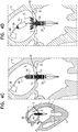
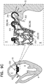
- FIGs. 4A-F are schematic illustrations of implantation of implant 20 at a native valve 10 of a heart 4 of a subject, in accordance with some applications of the invention.
- Valve 10 is shown as a mitral valve of the subject, disposed between a left atrium 6 and a left ventricle 8 of the subject.
- implant 20 may be implanted at another heart valve of the subject, mutatis mutandis.
- Figs. 4A-F show implant 20 being delivered transseptally via a sheath 88, the implant may alternatively be delivered by any other suitable route, such as transatrially, or transapically.
- Implant 20 is delivered, in its compressed state, to native valve 10 using a delivery tool 89 that is operable from outside the subject ( Fig. 4A ).
- implant 20 is delivered within a delivery capsule 90 of tool 89, which retains the implant in its compressed state.
- a transseptal approach such as a transfemoral approach, is shown.
- implant 20 is positioned such that at least flanges 54 are disposed downstream of the native valve (i.e., within ventricle 8).
- frame assembly 22 of implant 20 is as shown in Fig. 2A .
- flanges 54 are allowed to protrude radially outward, as described hereinabove, e.g., by releasing them from capsule 90 ( Fig. 4B ).
- capsule 90 may comprise a distal capsule-portion 92 and a proximal capsule-portion 94, and the distal capsule-portion may be moved distally with respect to implant 20, so as to expose flanges 54.
- frame assembly 22 of implant 20 is as shown in Fig. 2B .
- implant 20 is moved upstream, such that upstream support portion 40, in its compressed state, is disposed upstream of leaflets 12 (i.e., within atrium 6).
- the upstream movement of implant 20 causes flanges 54 to engage leaflets 12.
- Upstream support portion 40 is then allowed to expand such that it protrudes radially outward, as described hereinabove, e.g., by releasing it from capsule 90 ( Fig. 4D ).
- proximal capsule-portion 94 may be moved proximally with respect to implant 20, so as to expose upstream support portion 40.
- frame assembly 22 of implant 20 is as shown in Fig. 2D , in which: (i) distance d3 exists between upstream support portion 40 and flanges 54, (ii) the flanges have span d15, (iii) the upstream support portion has span d17, and (iv) tubular portion 32 has diameter d1.
- expansion of frame assembly 22 is inhibited by distal capsule-portion 92 (e.g., by inhibiting expansion of tubular portion 32), and/or by another portion of delivery tool 89 (e.g., a portion of the delivery tool that is disposed within lumen 38).
- implant 20 is allowed to expand toward its expanded state, such that tubular portion 32 widens to diameter d2, and the distance between upstream support portion 40 and flanges 54 reduces to distance d4 ( Fig. 4E ).
- This sandwiches tissue of valve 10 typically including annular tissue and/or leaflets 12) between upstream support portion 40 and flanges 54, thereby securing implant 20 at the valve.
- Fig. 4F shows delivery capsule 90 having been removed from the body of the subject, leaving implant 20 in place at valve 10.
- implant 20 is configured such that when tubular portion 32 is expanded, flanges 54 and upstream support portion 40 move a relatively large distance toward each other. This enables distance d3 to be relatively large, while distance d4 is sufficiently small to provide effective anchoring. As also described hereinabove, implant 20 is configured such that flanges 54 and upstream support portion 40 can extend radially outward a relatively large distance while tubular portion 32 remains compressed. It is hypothesized that for some applications, these configurations (independently and/or together) facilitate effective anchoring of implant 20, by facilitating placement of a relatively large proportion of valve tissue (e.g., leaflets 12) between the flanges and the upstream support portion prior to expanding tubular portion 32 and sandwiching the valve tissue.
- valve tissue e.g., leaflets 12
- valve tissue e.g., leaflets 12
- this configuration of implant 20 facilitates identifying correct positioning of the implant (i.e., with upstream support portion 40 upstream of leaflets 12 and flanges 54 downstream of the leaflets) prior to expanding tubular portion 32 and sandwiching the valve tissue.
- implant 20 defines a toroidal space 49 between flanges 54 and upstream support portion 40 (e.g., a space that is wider than distance d4).
- space 49 may have a generally triangular cross-section. It is hypothesized that for some such applications, in addition to sandwiching tissue of the native valve between upstream support portion 40 and flanges 54 (e.g., the tips of the flanges), space 49 advantageously promotes tissue growth therewithin (e.g., between leaflet tissue and covering 23), which over time further secures implant 20 within the native valve.
- FIG. 5 is a schematic illustration of a step in the implantation of implant 20, in accordance with some applications of the invention.
- Figs. 4A-F show an implantation technique in which flanges 54 are expanded prior to upstream support portion 40, for some applications the upstream support portion is expanded prior to the flanges.
- Fig. 5 shows a step in such an application.
- implant 20 may be implanted by causing flanges 54 to radially protrude before causing upstream support portion 40 to radially protrude, or may be implanted by causing the upstream support portion to protrude before causing the flanges to protrude.
- implant 20 is thereby configured to be deliverable in a downstream direction (e.g., transseptally, as shown, or transapically) or in an upstream direction (e.g., transapically or via the aortic valve).
- an operating physician may decide which delivery route is preferable for a given application (e.g., for a given subject, and/or based on available equipment and/or expertise), and implant 20 is responsively prepared for the chosen delivery route (e.g., by loading the implant into an appropriate delivery tool).
- downstream delivery of implant 20 may be performed by expanding flanges 54 first (e.g., as shown in Figs. 4A-F ) or by expanding upstream support portion 40 first (e.g., as shown in Fig. 5 ).
- upstream delivery of implant 20 may be performed by upstream support portion 40 first, or by expanding flanges 54 first.
- FIG. 6 is a schematic illustration of implant 20, in the state and position shown in Fig. 4D , in accordance with some applications of the invention.
- leaflets 12 of valve 10 are able to move, at least in part in response to beating of the heart.
- Frame (A) shows leaflets 12 during ventricular systole
- frame (B) shows the leaflets during ventricular diastole.
- blood is thereby able to flow from atrium 6 to ventricle 8, between leaflets 12 and implant 20.
- imaging techniques may be used to verify the position of implant 20, and/or positioning of leaflets 12 between upstream support portion 40 and flanges 54.
- Figs. 7A-B and 8A-B are schematic illustrations of frame assemblies 122 and 222 of respective implants, in accordance with some applications of the invention. Except where noted otherwise, frame assemblies 122 and 222 are typically identical to frame assembly 22, mutatis mutandis. Elements of frame assemblies 122 and 222 share the name of corresponding elements of frame assembly 22. Additionally, except where noted otherwise, the implants to which frame assemblies 122 and 222 belong are similar to implant 20, mutatis mutandis.
- Frame assembly 122 comprises (i) a valve frame 130 that comprises a tubular portion 132 and an upstream support portion 140 that typically comprises a plurality of arms 146, and (ii) an outer frame (e.g., a leg frame) 160 that circumscribes the valve frame, and comprises a plurality of legs 150 that each comprise a tissue-engaging flange 154.
- outer frame 160 comprises a ring 166 to which legs 150 are coupled. Ring 166 is defined by a pattern of alternating peaks and troughs, the peaks being fixed to frame 130 at respective coupling points 152, e.g., as described hereinabove for frame assembly 22, mutatis mutandis.
- Frame assembly 222 comprises (i) a valve frame 230 that comprises a tubular portion 232 and an upstream support portion 240 that typically comprises a plurality of arms 246, and (ii) an outer frame (e.g., a leg frame) 260 that circumscribes the valve frame, and comprises a plurality of legs 250 that each comprise a tissue-engaging flange 254.
- outer frame 260 comprises a ring 266 to which legs 250 are coupled. Ring 266 is defined by a pattern of alternating peaks and troughs, the peaks being fixed to frame 230 at respective coupling points 252, e.g., as described hereinabove for frame assembly 22, mutatis mutandis.
- tubular portions 32, 132 and 232 are each defined by a repeating pattern of cells that extends around the central longitudinal axis. Typically, and as shown, tubular portions 32, 132 and 232 are each defined by two stacked, tessellating rows of cells. In the expanded state of each tubular portion, these cells are typically narrower at their upstream and downstream extremities than midway between these extremities. For example, and as shown, the cells may be roughly diamond or astroid in shape.
- each arm 46 is attached to and extends from a site 35 that is at the upstream extremity of cells of the upstream row.
- each arm 146 or 246 is attached to and extends from a site 135 (assembly 122) or 235 (assembly 222) that is at the connection between two adjacent cells of the upstream row (alternatively described as being at the upstream extremity of cells of the downstream row).
- this lower position of the arms while maintaining the length of the lumen of the tubular portion, advantageously reduces the distance that the tubular portion (i.e., the downstream end thereof) extends into the ventricle of the subject, and thereby reduces a likelihood of inhibiting blood flow out of the ventricle through the left ventricular outflow tract. It is further hypothesized that this position of the arms reduces radial compression of the tubular portion by movement of the heart, due to greater rigidity of the tubular portion at sites 135 and 235 (which is supported by two adjacent cells) than at site 35 (which is supported by only one cell).
- the legs are circumferentially staggered with the arms of the upstream support portion (46, 146 and 246, respectively). This allows the legs to move in an upstream direction between the arms during expansion of the tubular portion (32, 132 and 232, respectively), facilitating application of greater sandwiching force on tissue of the native valve.
- the lower position of the arms of assemblies 122 and 222 includes circumferentially shifting the position of the arms by the width of half a cell. In order to maintain the circumferential staggering of the arms and legs, rings 166 and 266 (and thereby legs 150 and 250) are circumferentially shifted correspondingly.
- the peaks of rings 166 and 266 are generally aligned midway between these sites (i.e., at spaces of the cellular structure of the tubular portion). Appendages 168 (for assembly 122) or 268 (for assembly 222) facilitate fixing of the peak with respect to the tubular structure.
- appendages 168 are defined by valve frame 130 (e.g., by tubular portion 132 thereof) and extend (in a downstream direction) to the peaks of ring 166, to which they are fixed.
- each appendage 168 may define a valve-frame coupling element 131 that is fixed to a respective outer-frame coupling element 161 defined by outer frame 260.
- appendages 168 extend from sites 135.
- appendages 168 are integral with tubular portion 132 and/or in-plane with the tubular portion (e.g., are part of its tubular shape).
- appendages 268 are defined by outer frame 260, and extend (e.g., in an upstream direction) from the peaks of ring 266.
- appendages 268 extend to sites 235, to which they are fixed.
- each appendage 268 may define an outer-frame coupling element 261 that is fixed to a respective valve-frame coupling element 231 defined by valve frame 230 (e.g., by tubular portion 232 thereof).
- appendages 268 are integral with outer frame 260 and/or in-plane with adjacent portions of outer frame 260, such as ring 266.
- frame assembly 122 defines a hub at site 135, and frame assembly 222 defines a hub at site 235.
- apparatus therefore comprises:
- Figs. 9A-C are schematic illustrations of an implant 320 comprising a frame assembly 322, in accordance with some applications of the invention. Except where noted otherwise, frame assembly 322 is identical to frame assembly 122, and implant 300 is identical to the implant to which frame assembly 122 belongs, mutatis mutandis.
- Fig. 9A is a side-view of implant 320, and Fig. 9B is an isometric bottom-view of the implant.
- Frame assembly 122 comprises (i) a valve frame 330 that comprises a tubular portion 332 and an upstream support portion 340 that typically comprises a plurality of arms 346, and (ii) an outer frame (e.g., a leg frame) 360 that circumscribes the valve frame, and comprises a plurality of legs 350 that each comprise a tissue-engaging flange 354.
- outer frame 360 comprises a ring 366 to which legs 350 are coupled. Ring 366 is defined by a pattern of alternating peaks and troughs, the peaks being fixed to frame 330 at respective coupling points 352, e.g., as described hereinabove for frame assembly 22 and/or frame assembly 122, mutatis mutandis.
- Frame assembly 322 comprises an annular upstream support portion 340 that has an inner portion 342 that extends radially outward from the upstream portion (e.g., the upstream end) of tubular portion 332.
- Upstream support portion 340 further comprises one or more fabric pockets 344 disposed circumferentially around inner portion 342, each pocket of the one or more pockets having an opening that faces a downstream direction (i.e., generally toward the downstream end of implant 320).
- upstream support portion 340 has a single toroidal pocket 344 that extends circumferentially around inner portion 342.
- a covering 323 (e.g., similar to covering 23, described hereinabove, mutatis mutandis ) is disposed over arms 346, thereby forming pocket 344.
- arms 346 are shaped to form pocket 344 from covering 323. For example, and as shown, arms 346 may curve to form a hook-shape.
- portion 340 has a plurality of separate pockets 344, e.g., separated at arms 346.
- covering 323 is loosely-fitted (e.g., baggy) between radially-outward parts of arms 346, e.g., compared to inner portion 342, in which the covering is more closely-fitted between radially-inward parts of the arms.
- FIG. 9C shows implant 320 implanted at native valve 10.
- Pocket 344 is typically shaped and arranged to billow in response to perivalvular flow 302 of blood in an upstream direction. If ventricular systole forces blood in ventricle 8 between implant 320 and native valve 10, that blood inflates pocket 344 and presses it (e.g., covering 323 and/or the radially-outward part of arm 346) against tissue of atrium 6 (e.g., against the atrial wall), thereby increasing sealing responsively. It is hypothesized by the inventors that the shape and orientation of pocket 344 (e.g., the hook-shape of arms 346) facilitates this pressing radially-outward in response to the pocket's receipt of upstream-flowing blood.
- the shape and orientation of pocket 344 e.g., the hook-shape of arms 346
- Pocket(s) 344 may be used in combination with any of the implants described herein, mutatis mutandis.
- Fig. 10 is a schematic illustration of a frame assembly 422 of an implant, in accordance with some applications of the invention. Except where noted otherwise, frame assembly 422 is typically identical to frame assembly 122, mutatis mutandis. Elements of frame assembly 422 share the name of corresponding elements of frame assembly 122. Additionally, except where noted otherwise, the implant to which frame assembly 422 belongs is similar to implant the other implants described herein (e.g., implant 20), mutatis mutandis. Fig. 10 shows frame assembly 422 in an expanded state (e.g., in the absence of external deforming forces, such as those provided by a delivery tool during implantation, or by heart tissue after implantation).
- an expanded state e.g., in the absence of external deforming forces, such as those provided by a delivery tool during implantation, or by heart tissue after implantation.
- Frame assembly 422 comprises (i) a valve frame (e.g., an inner frame) 430 that comprises a tubular portion 432 and an upstream support portion 440 that typically comprises a plurality of radial arms 446, and (ii) an outer frame (e.g., a leg frame) 460 that circumscribes the valve frame, and comprises a plurality of legs 450 that each comprise a tissue-engaging flange 454.
- outer frame 460 comprises a ring 466 to which legs 450 are coupled.
- Ring 466 is defined by a pattern of alternating peaks and troughs, the peaks being fixed to frame 430 at respective coupling points 452, e.g., as described hereinabove for frame assemblies 22 and 122, mutatis mutandis.
- Tubular portion 432 has a diameter d26 (corresponding to diameter d2 of implant 20), and a transverse cross-sectional area that is a function of diameter d26.
- legs 450 are circumferentially staggered with arms 446 of upstream support portion 440. This allows the legs (e.g., flanges 454 thereof) to move in an upstream direction between the arms during deployment of the implant (although the presence of heart tissue typically reduces the amount by which flanges 454 move between arms 446).
- Fig. 10 shows frame assembly 422 in its expanded state, in which upstream support portion 440 (e.g., arms 446) and flanges 454 extend radially outward from tubular portion 432, and intersect at an intersection 470. Opposite intersections 470 define an intersect diameter d27.
- flanges 454 extend radially outward from the tubular portion and toward the upstream support portion 440 (i.e., outward and in an upstream direction).
- a toroidal space 449 is defined between flanges 454, upstream support portion 440, and tubular portion 432, the toroidal space circumscribing the tubular portion.
- the implant to which frame assembly 422 belongs is secured at the native valve by sandwiching heart tissue (e.g., leaflets 12 and/or the valve annulus) between upstream support portion 440 and flanges 54 (e.g., within space 449).
- heart tissue e.g., leaflets 12 and/or the valve annulus
- leaflets 12 are trapped in space 449.
- Space 449 is dimensioned to be sufficiently large to accommodate leaflets 12, because it has been observed by the inventors that if space 449 is too small, the implant tends to become secured to tissue that is suboptimally close to the middle of the native valve orifice (e.g., closer to the free edges of the leaflets), and to sit in a position that is suboptimally downstream (i.e., into ventricle 8).
- space 449 is dimensioned to be sufficiently small to accommodate leaflets 12 snugly, because it has been observed by the inventors that if space 449 is sufficiently small that the leaflets fill the space well (typically folding or bunching up within the space), sandwiching forces are applied to leaflet tissue throughout space 449. In contrast, if space 449 is too large, sandwiching forces may be applied to the leaflets only at or close to intersections 470, reducing the effectiveness of anchoring, and/or increasing a likelihood of damaging the tissue at or close to the intersections.
- an optimal size of space 449 i.e., a size that is sufficiently large to accommodate leaflets 12, but sufficiently small to do so snugly
- the space has a cross-sectional area 451 that is 5-10 percent (e.g., 5-8 percent, such as 6-7 percent or 6.5-7.5 percent) of the transverse cross-sectional area of tubular portion 432.
- this relative size is optimal across implants that have tubular portions of different diameters. For example:
- This optimal relative size range of area 451 is hypothesized by the inventors to apply to implants that have tubular portions that are narrower or wider than the above examples (e.g., 23 mm or 31 mm diameter).
- implants of different diameters d26 are provided, and each of the implants has a cross-sectional area 451 that is 5-10 percent (e.g., 5-8 percent, such as 6-7 percent or 6.5-7.5 percent) of the transverse cross-sectional area of the tubular portion 432 of the implant.
- the tubular portion 432 of one of the implants may have a have transverse cross-sectional area that is at least 15 percent (e.g., at least 30 percent) greater than another one of the implants.
- Tubular portion 432 has an upstream end 434 and a downstream end 436.
- arms 446 are attached to and extend from sites 435 that are downstream of upstream end 434, e.g., at the connection between two adjacent cells of the upstream row of cells of tubular portion 432 (alternatively described as being at the upstream extremity of cells of the downstream row of cells).
- each arm 446 defines, respectively: (i) an ascending portion 446a that extends in an upstream direction past upstream end 434 of tubular portion 432 (e.g., by a distance d28), (ii) an arch portion 446b that curves in a downstream direction to form an arch (portion 446b may alternatively be described as being convex in an upstream direction), and (iii) a lateral portion 446c that curves in an upstream direction.
- arch portion 446b curves in the downstream direction as far as (and typically past) tips 455 of flanges 454 (i.e., at the arch portion, each arm 446 extends below (i.e., further downstream than) adjacent tips 455).
- intersections 470 are generally close to where arms 446 begin to curve upstream.
- a height d29 is the height, along the central longitudinal axis of the implant, between (i) the crest of arch portion 446b, and (ii) intersection 470.
- height d29 is 0.5-3.5 mm (e.g., 1.8-2.6 mm).
- a height d30 is the height, along the central longitudinal axis of the implant, between (i) the crest of arch portion 446b, and (ii) site 435.
- height d30 is 4-7.5 mm (e.g., 5.2-6.5 mm).
- arms 446 extend (i) radially outward and above (a) upstream end 434 and (b) the tips of flanges 454, and then (ii) further radially outward and below (a) upstream end 434 and/or (b) the tips of flanges 454 (i.e., toward the flanges).
- the above configuration of arm 46 increases the size of toroidal space 449 (compared to a similar arm in which d28 and/or d29 are smaller), e.g., providing an optimal cross-sectional area 451, as described hereinabove.
- the arms do not have arch portions that extend above (i) the upstream end of the respective tubular portion, or (ii) the tips of the respective flanges.
- the lateral portions of these arms do extend upwardly, the lateral portions are radially outward of the flanges, and therefore do not increase the cross-sectional area of the toroidal space defined by these frame assemblies.
- an end 446d i.e., the lateral extremity of arm 446 is disposed further in an upstream direction than arch portion 446b.
- the outer stent frame (e.g., leg frame) 460 has a radial thickness d24 (i.e., a thickness measured along an axis that extends radially outward from the central longitudinal axis of the implant) that is greater than a radial thickness d25 of inner stent frame (e.g., valve frame) 430. That is, the outer stent frame is radially thicker than the inner stent frame.
- first wall thickness e.g., equal to d25
- second wall thickness e.g., equal to d24
- other methods of manufacture including 3D printing, may be used.
- thickness d24 is at least 10 percent (e.g., at least 20 percent, such as at least 30 percent) and/or no more than 80 percent (e.g., no more than 50 percent) greater than thickness d25.
- thickness d24 is 0.6-0.8 mm (e.g., 0.7-0.75 mm, e.g., 0.71-0.73 mm, such as 0.72 mm)
- thickness d25 is 0.45-0.65 mm (e.g., 0.5-0.55 mm, e.g., 0.52-0.54 mm, such as 0.53 mm).
- outer stent frame e.g., leg frame
- inner stent frame e.g., valve frame
- apparatus comprising:
- Providing a frame assembly in which the outer frame has greater radial thicknesses is hypothesized by the inventors to advantageously provide (i) radially-expansive strength (and resistance to radially-inward deformation) to the portion of the frame assembly in which the prosthetic leaflets are disposed, and (ii) rigidity (and resistance to fatigue) to legs 450.
- tubular portion 432 defines an inner-stent-frame relaxed expanded diameter (which is measured as an outer diameter of the tubular portion) that is greater than an outer-stent-frame relaxed expanded diameter defined by ring 466 (which is measured as an inner diameter of the ring).
- the inner-stent-frame relaxed expanded diameter is 0.5-1.5 (e.g., 0.5-1, such as 0.8) mm greater than the outer-stent-frame relaxed expanded diameter.
- frame 460 constrains tubular portion 432 to an inner-stent-frame constrained expanded diameter that is smaller than the inner-stent-frame relaxed expanded diameter. Therefore, even in the relaxed expanded state of frame assembly 422 (i.e., the state shown in Fig. 10 ), residual stress is typically present in frame 430 (e.g., tubular portion 432 thereof) and/or frame 460 (e.g., ring 466 thereof). Additionally, when the frame assembly is in its compressed state, and throughout its expansion into its expanded state, circumferential contact (and reciprocating expansive and compressive forces) is maintained between frame 460 and tubular portion 432.
- this optional residually-stressed configuration advantageously increases the strength of the frame assembly (e.g., the tubular portion), and in particular its resistance to deformation, e.g., in response to forces applied directly to the frame assembly by tissue of the native valve, and/or applied indirectly to the frame assembly during systole when ventricular blood is forced against the prosthetic leaflets, which pull on the frame assembly.
- frames 430 and 460 are fixed to each other independently of any additional coupling that might be provided by the residually-stressed configuration.
- the frames are fixed to each other at coupling points 452, e.g., by welding, soldering, crimping, stitching (e.g., suturing), gluing, or any other suitable technique.
- the frames are also fixed to each other at commissures of the implant. That is, the residually-stressed configuration is provided for strength and rigidity of the frame assembly (and for ensuring maintenance of circumferential contact between the frames), rather than for coupling of the frames to each other.
- FIGs. 11A-C are schematic illustrations of a connector 510 and a commissure 500 of a prosthetic valve, in accordance with some applications of the invention.
- Connector 510 typically comprises a flexible sheet 512 that is folded to define elements of the connector. Further typically, sheet 512 is a single, unitary sheet (e.g., cut from a single piece of stock material).
- Fig. 11A shows two perspective views of connector 510 (e.g., sheet 512 thereof) in its folded state, and Fig. 11B shows its unfolded state.
- Fig. 11C shows connector 510 fixed to frame assembly 422 at commissure 500. Commissure 500 is described with respect to the implant to which frame assembly 422 belongs, although it may be used in combination with the other prosthetic valves described herein, and/or with other prosthetic valves, mutatis mutandis.
- the implant to which frame assembly 422 belongs defines a plurality of commissures 500 at which two of the prosthetic leaflets of the implant (e.g., leaflets 58 or similar) meet, and are fixed to the frame assembly.
- the implant comprises a plurality of stitches (e.g., stitches) 502, via which commissural portions of the two prosthetic leaflets are secured to the frame assembly.
- the stitches secure the prosthetic leaflets to the inner stent frame (frame 430, e.g., tubular portion 432 thereof) and to the outer stent frame (frame 460). That is, the leaflets are not coupled to the outer stent frame merely by being fixed to the inner stent frame, which in turn is coupled to the outer stent frame.
- the leaflets are fixed to both frames by stitches 502. Because (as described hereinabove) (i) frame 460 is radially thicker than frame 430, and (ii) the relative diameters of the frames results in residual stress and maintained circumferential contact between frames 430 and 460, the fixation of the leaflets to both frames advantageously provides the implant with enhanced resistance to pulling of commissures 500 radially inward by the prosthetic leaflets when ventricular pressure increases during ventricular systole.
- connector 510 typically comprising primarily or solely a fabric
- Connector 510 is shaped to define a plurality of flaps 504, and a leaflet-receptacle 514 comprising one or more (e.g., two) leaflet-engaging tabs 506, such as a first leaflet-engaging tab 506a and a second leaflet-engaging tab 506b.
- connector 510 is shaped to define a panel (e.g., a plate) 508, tabs 506 protrude from of one side of the panel, and each flap 504 folds over a respective portion of the other side of the panel.
- leaflet-engaging tabs 506 e.g., to respective leaflet-engaging tabs.
- Flaps 504 are stitched to frames 430 and 460 - i.e., are fixed to the frames by stitches 502.
- flaps 504 are folded over or wrapped around elements of frames 430 and 460, and are fixed in this disposition by stitches 502, thereby providing increased strength to the fixation of the leaflets to the frames (and of the frames to each other).
- connector 510 comprises four flaps 504.
- flaps 504 are arranged in a circuit such that each flap has two adjacent flaps around the circuit, and the fold axis ax2 of each flap is oriented at 60-120 degrees (e.g., 70-110 degrees, e.g., 80-100 degrees) from the fold axis of each of its adjacent flaps.
- the frame to which connector 510 is to be connected has a cellular structure with roughly diamond-shape cells, such an arrangement facilitates attachment of the connector to the frame.
- connector 510 has four flaps arranged roughly in a diamond shape, with two upstream flaps 504a tapering away from each other in a downstream direction, and two downstream flaps 504b tapering toward each other in a downstream direction.
- Each upstream flap 504a is typically folded over or wrapped around an element of frame 430 and an element of frame 460.
- FIG. 11C at commissure 500, elements of frame 430 align with elements of frame 460, and flaps 504a are arranged to align with these elements of both frames. Flaps 504 are folded over or wrapped around these elements of both frames, and are fixed to these elements by stitches 502.
- downstream flaps 504b In the position of downstream flaps 504b, elements of frame 430 do not align with elements of frame 460, and may even be perpendicular to them.
- Downstream flaps 504b are arranged to align with elements of frame 430, and are folded over or wrapped around elements, but typically not over or around elements of frame 460.
- the elements of frame 430, and flaps 504b, are stitched to elements of frame 460; these stitches are indicated by the reference numeral 502b, while the stitches that secure flaps over or around frame elements are indicated by the reference numeral 502a.
- panel 508 is also stitched to elements of frame 430 and/or frame 460; these stitches are indicated by the reference numeral 502c.
- frames 430 and 460 are thereby fixed to each other at commissures 500 (i.e., in addition to at coupling points 452).
- connector 510 and/or the stitches may secure the leaflets only to inner frame 430, such that the leaflets are coupled to outer frame 460 only via inner frame 430.
- a connector comprising a flexible sheet (e.g., sheet 512) that is folded to define: (i) a panel (e.g., panel 508) that has a first side (e.g., side 508a), and a second side (e.g., side 508b) that is opposite the first side; (ii) a leaflet receptacle (e.g., receptacle 514), disposed on the first side of the panel, and protruding in the first direction away from the panel; and (iii) a plurality of flaps (e.g., flaps 504), each flap folded about a respective fold axis (e.g., axis ax2) such that at least part of each flap is disposed on the second side of the panel.
- a panel e.g., panel 508
- a leaflet receptacle e.g., receptacle 514
- flaps e.g., flaps 504
- Receptacle 514 is configured to sandwich one or more prosthetic leaflets between leaflet-engaging tabs 506a and 506b.
- stitching holes 516 are defined in leaflet-engaging tabs 506 to guide the introduction of stitches which will secure the leaflets sandwiched between the tabs.
- holes 516 are arranged into rows.
- each leaflet-engaging tab 506 may define a first row 518a of stitching holes and a second row 518b of stitching holes, the rows of one tab being aligned with the rows of the other tab.
- rows 518a and 518b diverge from each other at an angle alpha_3, typically such that that progressively downstream parts of the rows are progressively further from each other.
- angle alpha_3 may be 10-45 degrees (e.g., 10-30 degrees, e.g., 15-25 degrees, such as about 20 degrees).
- sheet 512 is folded such that each leaflet-engaging tab 506 comprises an outer layer 520o, and an inner layer 520i that is positioned to be sandwiched between the outer layer and the one or more leaflets.
- sheet 512 defines a plane (i.e., the plane of the page).
- sheet 512 defines, in the plane, (i) panel 508 at a medial region of sheet 512, (ii) flaps 504, disposed peripherally to the panel, and (iii) first and second tab portions 526, also disposed peripherally from the panel.
- Each tab portion 526 includes outer layer 520o and inner layer 520i, and in the folded state, defines a respective leaflet-engaging tab 506.
- sheet 512 further defines bridging elements 522, via each of which a respective tab portion 526 is connected to panel 508. Flaps 504 are connected to panel 508 independently of the bridging elements.
- tab portions 526 flank panel 508 by being disposed, in the plane, on opposing lateral sides of the panel.
- panel 508, tab portions 526, and bridging elements 522 are arranged in a row that defines a lateral axis ax3 in the plane, axis ax3 passing through the panel, tab portions, and bridging elements.
- Axis ax3 typically passes between upstream flaps 504a and downstream flaps 504b.
- the fold axis ax2 of each flap 504 is disposed at an angle alpha 4 that is 30-60 degrees from lateral axis ax3.
- bridging elements 522 extend from respective edges of panel 508 and toward each other across first side 508a of the panel, and each of the leaflet-engaging tabs 506 protrudes from its respective bridging element away from the first side of the panel in the direction that the first side of the panel faces.
- FIGs. 12A-B and 13A-F are schematic illustrations of another connector 610 for connecting prosthetic leaflets (e.g., leaflets 58) to a frame of a prosthetic valve implant, in accordance with some applications of the invention.
- Connector 610 may be used with any of the implants described herein, or with a different prosthetic valve, mutatis mutandis.
- Connector 610 typically comprises a flexible sheet 612 that is folded to define elements of the connector. Further typically, sheet 612 is a single, unitary sheet (e.g., cut from a single piece of stock material).
- Fig. 12A shows two perspective views of connector 610 (e.g., sheet 612 thereof) in its folded state, and Fig. 12B shows its unfolded state.
- Fig. 12B and 13A-F opposing sides of the sheet are differently shaded, e.g., as demonstrated by a corner of sheet 612 being curled over in Fig. 12B to show its reverse side.
- Connector 610 (e.g., in its folded state) is shaped to define a plurality of flaps 604, and a leaflet-receptacle 614 comprising one or more (e.g., two) leaflet-engaging tabs 606, such as a first leaflet-engaging tab 606a and a second leaflet-engaging tab 606b.
- Connector 610 is typically shaped to define a panel (e.g., a plate) 608. In the folded state, tabs 606 protrude from of a first side 608a of the panel, and each flap 604 folds over a second side 608b of the panel (e.g., a respective portion thereof).
- Flaps 604 are folded over or wrapped around elements of the frame of the prosthetic valve implant, e.g., as shown in Fig. 13F . Typically, flaps 604 are fixed in this disposition by stitches (not shown).
- connector 610 comprises four flaps 604, typically two upstream flaps 604a and two downstream flaps 604b.
- flaps 604 are arranged in a circuit such that each flap has two adjacent flaps around the circuit, and the fold axis ax4 of each flap is oriented at 60-120 degrees (e.g., 70-110 degrees, e.g., 80-100 degrees) from the fold axis of each of its adjacent flaps.
- the frame to which connector 610 is to be connected has a cellular structure with roughly diamond-shape cells, such an arrangement facilitates attachment of the connector to the frame, e.g., as shown in Fig. 13F .
- a connector comprising a flexible sheet (e.g., sheet 612) that is folded to define: (i) a panel (e.g., panel 608) that has a first side (e.g., side 608a), and a second side (e.g., side 608b) that is opposite the first side; (ii) a leaflet receptacle (e.g., receptacle 614), disposed on the first side of the panel, and protruding in a first direction away from the panel; and (iii) a plurality of flaps (e.g., flaps 604), each flap folded about a respective fold axis (e.g., axis ax4) such that at least part of each flap is disposed on the second side of the panel.
- a panel e.g., panel 608
- a leaflet receptacle e.g., receptacle 614
- flaps e.g., flaps 604
- Receptacle 614 is configured to sandwich one or more prosthetic leaflets between leaflet-engaging tabs 606a and 606b.
- stitching holes 616 are defined in leaflet-engaging tabs 606 to guide the introduction of stitches which will secure the leaflets sandwiched between the tabs.
- holes 616 are arranged into rows.
- each leaflet-engaging tab 606 may define a first row 618a of stitching holes and a second row 618b of stitching holes, the rows of one tab being aligned with the corresponding rows of the other tab.
- rows 618a and 618b diverge from each other at an angle alpha_5, typically such that that progressively downstream parts of the rows are progressively further from each other.
- angle alpha_5 may be 10-45 degrees (e.g., 10-30 degrees, e.g., 15-25 degrees, such as about 20 degrees).
- Downstream is defined by the direction in which the prosthetic leaflets facilitate one-way fluid flow, which itself is in part dependent on the orientation of the attachment of the leaflets to connectors 610.
- each leaflet-engaging tab 606 comprises an outer layer 620o, and an inner layer 620i that is positioned to be sandwiched between the outer layer and the one or more leaflets.
- rows 618a and 618b are defined by inner layer 620i
- a third row 618c of stitching holes is defined by outer layer 620, and the folding of sheet 612 is such that row 618c aligns with row 618a. For such applications, only row 618c is visible in the folded state.
- an angle alpha_7 between rows 618a and 618c is typically 40-120 degrees (e.g., 40-90 degrees, e.g., 40-70 degrees, e.g., 40-60 degrees, such as 50-60 degrees).
- sheet 612 defines a plane (i.e., the plane of the page).
- sheet 612 defines, in the plane, (i) panel 608 at a medial region of sheet 612, (ii) flaps 604, disposed peripherally to the panel, and (iii) first and second tab portions 626, also disposed peripherally from the panel.
- Each tab portion 626 includes outer layer 620o and inner layer 620i, and in the folded state, defines a respective leaflet-engaging tab 606.
- Sheet 612 further defines bridging elements 622, via each of which a respective tab portion 626 is connected to panel 608. Flaps 504 are connected to panel 508 via the bridging elements.
- each flap 604 is disposed on first side 608a of panel 608, and part of each flap is disposed on second side 608b.
- bridging elements 622 are typically disposed on first side 608a, and each flap 604 extends from one of the bridging elements and around panel 608 such that part of the flap is disposed on side 608a, and part is disposed on side 608b.
- tab portions 626 flank panel 608 by being disposed, in the plane, on opposing lateral sides of the panel.
- panel 608, tab portions 626, and bridging elements 622 are arranged in a row that defines a lateral axis ax5 in the plane, axis ax5 passing through the panel, tab portions, and bridging elements.
- Axis ax5 typically passes between upstream flaps 604a and downstream flaps 604b.
- the fold axis ax4 of each flap 604 is disposed at an angle alpha_6 that is 30-70 degrees from lateral axis ax5.
- Sheet 612 typically further defines a lapel 640 that, in the unfolded state, is lateral to each tab portion 626.
- Lapels 640 are described further hereinbelow.
- bridging elements 622 extend from respective edges of panel 608 and toward each other across first side 608a of the panel, and each of the leaflet-engaging tabs 606 protrudes from its respective bridging element away from the first side of the panel in the direction that the first side of the panel faces.
- Figs. 13A-F show steps in the folding of sheet 612 from the unfolded state to the folded state, in order to define connector 610, in accordance with some applications of the inventions.
- Folds are made in downstream regions of tab portions 626, e.g., the downstream edge of each layer 610o and each layer 610i is folded over to form respective folds 628 ( Fig. 13A ). This will provide each leaflet-engaging tab with a cushion 630, described hereinbelow.
- Folds 628 may be secured by stitching.
- Sheet 612 is folded in half along its longitudinal axis ax6, bringing tab portions 626 together ( Fig. 13B ).
- Commissural portions of two leaflets 58 e.g., a first leaflet 58a and a second leaflet 58b
- the positioning of the leaflets is typically such that they are disposed between the holes 616 of one portion 626, and those of the other portion 626.
- Holes 616 of row 618b of both portions 626 are stitched together, as indicated by reference numeral 632. The stitches therefore pass through leaflets 58a and 58b, thereby securing them to connector 610.
- tab portions 626 are folded back against themselves, thereby defining inner layer 620i and outer layer 620o ( Fig. 13C ), and aligning rows 618c with rows 618a. Holes 616 of rows 618a and 618b are now hidden by outer layer 620o. Rows 618c and 618a of one tab portion 626, leaflets 58a and 58b, and rows 618a and 618c of the other tab portion are then stitched together, as indicated by reference numeral 634. This reinforces the connection of the leaflets to connector 610. Thus, tab portions 626 are formed into leaflet-engaging tabs 606.
- step 13C the folding in half of sheet 612 shown in step 13B is reversed, mutatis mutandis, moving bridging elements 622 away from each other and folding them against panel 608 ( Fig. 13D ).
- regions of each leaflet 58 that are disposed beyond row 618c become disposed between bridging elements 622 and panel 608.
- the step shown in Fig. 13C brings lapels 640 into contact with bridging elements 622.
- the step shown in Fig. 13D typically causes each bridging element 622 to move with the bridging element 622 with which it is in contact, and folding with respect to outer layer 620i of leaflet-engaging tabs 606.
- stitches are passed through lapel 640, bridging element 622, leaflet 58, and panel 608. This stitching may be an independent step, or may be achieved when securing flaps 604 to the frame of the prosthetic valve, e.g., as described hereinbelow.
- Fig. 13E shows perspective views of the state shown in Fig. 13D .
- Each leaflet 58 has a downstream edge 638.
- leaflet-engaging tabs 606 typically extend in a downstream direction beyond downstream edges 638.
- cushions 630 are typically positioned such that at least part of each cushion is disposed further downstream than downstream edges 638. Tabs 606 and/or cushions 630 are thereby configured to inhibit movement of the commissural portion of each leaflet 58 (and especially of downstream edges 638) toward the frame of the prosthetic valve. It is hypothesized by the inventors that this reduces a likelihood of leaflets 58 becoming damaged over time due to contact with the frame.
- connector 610 is secured to the frame of the prosthetic valve ( Fig. 13F ).
- Flaps 604 are folded over components of the frame of the prosthetic valve (which are shown in phantom), and secured by stitching. For some applications, some of this stitching may pass through several elements, such as flaps 604, panel 608, leaflets 58, bridging elements 622, and/or lapels 640.
- FIGS. 13A-F show a particular sequence, and although some of the steps are necessarily performed before others, it is to be understood that some of the steps may be performed in a different order to that shown. For example, folds 628 may be folded at a later stage to that shown.
- three connectors 610 are used to connect three leaflets 58 at three commissures to the frame of the prosthetic valve, to form a tri-leaflet check-valve.
- a prosthetic valve from two (e.g., concentric) frames
- the ability to divide the frame elements required between the two frames in a manner that would not be possible in a single frame, or in a manner that, if a single frame were used, would increase the size (e.g., the diameter or the length) of the implant in its compressed state.
- the use of two frames allows different sizes of the implant to be compressed ("crimped") to the same or similar diameter, and for some such applications, to be delivered using the same delivery tool (e.g., delivery tool 89).
- an implant of a larger size may have a lumen diameter that is at least 15 percent greater than the lumen diameter of an implant of a smaller size (in their respective expanded states), but in their compressed states, the diameter of the implant of the larger size may be no more than 2 percent greater than the diameter of the implant of the smaller size.
- a delivery tool is provided for use with different sizes of the implant, e.g., with the implants provided separately.
- a kit is provided containing a delivery tool and implants of different sizes.
- radially outward means portions of the element are disposed progressively further outward from a central point (such as longitudinal axis ax1 or tubular portion 32), but does not necessarily mean disposed at 90 degrees with respect to longitudinal axis ax1.
- flanges 54 may extend radially outward at 90 degrees with respect to longitudinal axis ax1, but may alternatively extend radially outward at a shallower angle with respect to the longitudinal axis.
Landscapes
- Health & Medical Sciences (AREA)
- Engineering & Computer Science (AREA)
- Cardiology (AREA)
- Biomedical Technology (AREA)
- Life Sciences & Earth Sciences (AREA)
- Transplantation (AREA)
- Heart & Thoracic Surgery (AREA)
- Vascular Medicine (AREA)
- Oral & Maxillofacial Surgery (AREA)
- Animal Behavior & Ethology (AREA)
- General Health & Medical Sciences (AREA)
- Public Health (AREA)
- Veterinary Medicine (AREA)
- Manufacturing & Machinery (AREA)
- Mechanical Engineering (AREA)
- Prostheses (AREA)
Claims (6)
- Appareil destiné à être utilisé avec le cœur d'un sujet, l'appareil comprenant :un cadre interne d'une endoprothèse (430) qui :définit une partie tubulaire (432) et une pluralité d'éléments d'accouplement de cadre interne (452), etprésente un état expansé détendu dans lequel la partie tubulaire définit un diamètre expansé détendu du cadre d'endoprothèse interne ; etun cadre d'endoprothèse externe (460), qui :
définit une bague (466) et une pluralité d'éléments d'accouplement de cadre externe (452), et présente un état expansé détendu dans lequel l'anneau définit un diamètre expansé détendu du cadre d'endoprothèse externe qui est plus petit que le diamètre de cadre d'endoprothèse interne expansé, dans lequel :ensemble, le cadre d'endoprothèse interne (430) et le cadre d'endoprothèse externe (460) définissent au moins une partie d'un ensemble cadre (422) dans lequel les éléments d'accouplement de cadre externe (452) sont fixés aux éléments d'accouplement de cadre interne (452) et la bague (466) circonscrit la partie tubulaire (432), etl'ensemble cadre (422) :comprend en outre une pluralité de prothèses valvaires (58) attachées à la partie tubulaire (432) et disposées à l'intérieur de celle-ci,présente un état comprimé dans lequel l'ensemble cadre (422) peut avancer de manière transluminale vers le cœur, etest extensible dans un état expansé dans lequel la partie tubulaire (432) définit un diamètre expansé contraint du cadre d'endoprothèse interne qui est plus petit que le diamètre expansé détendu du cadre d'endoprothèse interne et en outre dans lequel :
l'appareil définit une pluralité de commissures (500), et, au niveau de chacune des commissures (500) :l'appareil comprend une pluralité de coutures (502), etdes parties de commissures respectives de deux des prothèses valvaires (58) sont attachées au cadre d'endoprothèse interne (430) et au cadre d'endoprothèse externe (460) par l'intermédiaire de la pluralité de coutures (502) ;
etle cadre externe (460) est attaché au cadre interne (430) par à la fois (i) la fixation des éléments d'accouplement du cadre externe aux éléments d'accouplement du cadre interne (452) et (ii) la couture du cadre externe (460) au cadre interne (430) au niveau des commissures (500). - Appareil selon la revendication 1, dans lequel le cadre externe (460) est accouplé au cadre interne (430) de telle sorte que :à l'état comprimé de l'ensemble cadre (422), le cadre externe (460) est en contact circonférentiel avec la partie tubulaire (432), ettout au long de l'expansion de l'ensemble cadre (422) jusqu'à son état expansé, un contact circonférentiel est maintenu entre le cadre externe (460) et la partie tubulaire (432).
- Appareil selon la revendication 1, dans lequel les éléments d'accouplement de cadre externe (452) sont soudés aux éléments d'accouplement de cadre interne (452).
- Appareil selon la revendication 1, dans lequel, au niveau de chaque commissure (500), l'appareil comprend un raccord en tissu (510) auquel les parties de commissures des deux prothèses (58) sont attachées, et la pluralité de coutures (502) attachent les parties de commissures des deux prothèses (58) au cadre d'endoprothèse interne (430) et au cadre d'endoprothèse externe (460) en étant attachées au raccord en tissu (510).
- Appareil selon la revendication 4, dans lequel le raccord en tissu (510) est formé pour définir (i) un panneau (508) ayant un premier côté et un second côté, (ii) une ou plusieurs languettes de prise de prothèse (506) auxquelles les parties de commissures des deux prothèses sont cousues, les languettes faisant saillie du premier côté du panneau, et (iii) une pluralité de rabats (504), enroulés autour d'éléments d'endoprothèse interne (430) et d'éléments du cadre d'endoprothèse externe (460), et attachés ainsi par couture.
- Appareil selon la revendication 1, dans lequel, à l'état expansé détendu, la partie tubulaire (432) est en forme de tonneau.
Priority Applications (2)
| Application Number | Priority Date | Filing Date | Title |
|---|---|---|---|
| EP21157988.3A EP3848003B1 (fr) | 2016-08-10 | 2017-08-08 | Valve prothétique avec cadres concentriques |
| EP25155882.1A EP4523659A3 (fr) | 2016-08-10 | 2017-08-08 | Valvule prothétique à cadres concentriques |
Applications Claiming Priority (2)
| Application Number | Priority Date | Filing Date | Title |
|---|---|---|---|
| US201662372861P | 2016-08-10 | 2016-08-10 | |
| PCT/IL2017/050873 WO2018029680A1 (fr) | 2016-08-10 | 2017-08-08 | Valve prothétique avec cadres concentriques. |
Related Child Applications (3)
| Application Number | Title | Priority Date | Filing Date |
|---|---|---|---|
| EP25155882.1A Division EP4523659A3 (fr) | 2016-08-10 | 2017-08-08 | Valvule prothétique à cadres concentriques |
| EP21157988.3A Division EP3848003B1 (fr) | 2016-08-10 | 2017-08-08 | Valve prothétique avec cadres concentriques |
| EP21157988.3A Division-Into EP3848003B1 (fr) | 2016-08-10 | 2017-08-08 | Valve prothétique avec cadres concentriques |
Publications (2)
| Publication Number | Publication Date |
|---|---|
| EP3496664A1 EP3496664A1 (fr) | 2019-06-19 |
| EP3496664B1 true EP3496664B1 (fr) | 2021-09-29 |
Family
ID=59626647
Family Applications (5)
| Application Number | Title | Priority Date | Filing Date |
|---|---|---|---|
| EP21157988.3A Active EP3848003B1 (fr) | 2016-08-10 | 2017-08-08 | Valve prothétique avec cadres concentriques |
| EP25155882.1A Pending EP4523659A3 (fr) | 2016-08-10 | 2017-08-08 | Valvule prothétique à cadres concentriques |
| EP17752184.6A Active EP3496664B1 (fr) | 2016-08-10 | 2017-08-08 | Valve prothétique avec cadres concentriques. |
| EP18752635.5A Active EP3664748B1 (fr) | 2016-08-10 | 2018-08-07 | Valve prothétique avec connecteurs de feuillets |
| EP24212525.0A Pending EP4480455A3 (fr) | 2016-08-10 | 2018-08-07 | Valvule prothétique à connecteurs de feuillet |
Family Applications Before (2)
| Application Number | Title | Priority Date | Filing Date |
|---|---|---|---|
| EP21157988.3A Active EP3848003B1 (fr) | 2016-08-10 | 2017-08-08 | Valve prothétique avec cadres concentriques |
| EP25155882.1A Pending EP4523659A3 (fr) | 2016-08-10 | 2017-08-08 | Valvule prothétique à cadres concentriques |
Family Applications After (2)
| Application Number | Title | Priority Date | Filing Date |
|---|---|---|---|
| EP18752635.5A Active EP3664748B1 (fr) | 2016-08-10 | 2018-08-07 | Valve prothétique avec connecteurs de feuillets |
| EP24212525.0A Pending EP4480455A3 (fr) | 2016-08-10 | 2018-08-07 | Valvule prothétique à connecteurs de feuillet |
Country Status (6)
| Country | Link |
|---|---|
| US (6) | US10856975B2 (fr) |
| EP (5) | EP3848003B1 (fr) |
| CN (5) | CN109789018B (fr) |
| CA (2) | CA3031187A1 (fr) |
| ES (2) | ES3018641T3 (fr) |
| WO (2) | WO2018029680A1 (fr) |
Cited By (14)
| Publication number | Priority date | Publication date | Assignee | Title |
|---|---|---|---|---|
| US11311376B2 (en) | 2019-06-20 | 2022-04-26 | Neovase Tiara Inc. | Low profile prosthetic mitral valve |
| US11357622B2 (en) | 2016-01-29 | 2022-06-14 | Neovase Tiara Inc. | Prosthetic valve for avoiding obstruction of outflow |
| US11389291B2 (en) | 2013-04-04 | 2022-07-19 | Neovase Tiara Inc. | Methods and apparatus for delivering a prosthetic valve to a beating heart |
| US11413139B2 (en) | 2011-11-23 | 2022-08-16 | Neovasc Tiara Inc. | Sequentially deployed transcatheter mitral valve prosthesis |
| US11419720B2 (en) | 2010-05-05 | 2022-08-23 | Neovasc Tiara Inc. | Transcatheter mitral valve prosthesis |
| US11464631B2 (en) | 2016-11-21 | 2022-10-11 | Neovasc Tiara Inc. | Methods and systems for rapid retraction of a transcatheter heart valve delivery system |
| US11491006B2 (en) | 2019-04-10 | 2022-11-08 | Neovasc Tiara Inc. | Prosthetic valve with natural blood flow |
| US11497602B2 (en) | 2012-02-14 | 2022-11-15 | Neovasc Tiara Inc. | Methods and apparatus for engaging a valve prosthesis with tissue |
| US11602429B2 (en) | 2019-04-01 | 2023-03-14 | Neovasc Tiara Inc. | Controllably deployable prosthetic valve |
| US11737872B2 (en) | 2018-11-08 | 2023-08-29 | Neovasc Tiara Inc. | Ventricular deployment of a transcatheter mitral valve prosthesis |
| US11779742B2 (en) | 2019-05-20 | 2023-10-10 | Neovasc Tiara Inc. | Introducer with hemostasis mechanism |
| US11793640B2 (en) | 2017-08-25 | 2023-10-24 | Neovasc Tiara Inc. | Sequentially deployed transcatheter mitral valve prosthesis |
| US11998447B2 (en) | 2019-03-08 | 2024-06-04 | Neovasc Tiara Inc. | Retrievable prosthesis delivery system |
| US12109111B2 (en) | 2015-12-15 | 2024-10-08 | Neovasc Tiara Inc. | Transseptal delivery system |
Families Citing this family (70)
| Publication number | Priority date | Publication date | Assignee | Title |
|---|---|---|---|---|
| US8870950B2 (en) | 2009-12-08 | 2014-10-28 | Mitral Tech Ltd. | Rotation-based anchoring of an implant |
| US20110224785A1 (en) | 2010-03-10 | 2011-09-15 | Hacohen Gil | Prosthetic mitral valve with tissue anchors |
| US11653910B2 (en) | 2010-07-21 | 2023-05-23 | Cardiovalve Ltd. | Helical anchor implantation |
| US9763657B2 (en) | 2010-07-21 | 2017-09-19 | Mitraltech Ltd. | Techniques for percutaneous mitral valve replacement and sealing |
| CA3035048C (fr) | 2010-12-23 | 2021-05-04 | Mark Deem | Systeme de reparation et remplacement de valvule mitrale |
| EP3417813B1 (fr) | 2011-08-05 | 2020-05-13 | Cardiovalve Ltd | Remplacement percutané d'une valvule mitrale |
| WO2013021374A2 (fr) | 2011-08-05 | 2013-02-14 | Mitraltech Ltd. | Techniques pour le remplacement et la fixation percutanés d'une valvule mitrale |
| US8852272B2 (en) | 2011-08-05 | 2014-10-07 | Mitraltech Ltd. | Techniques for percutaneous mitral valve replacement and sealing |
| US9345573B2 (en) | 2012-05-30 | 2016-05-24 | Neovasc Tiara Inc. | Methods and apparatus for loading a prosthesis onto a delivery system |
| US8628571B1 (en) | 2012-11-13 | 2014-01-14 | Mitraltech Ltd. | Percutaneously-deliverable mechanical valve |
| US9968443B2 (en) | 2012-12-19 | 2018-05-15 | W. L. Gore & Associates, Inc. | Vertical coaptation zone in a planar portion of prosthetic heart valve leaflet |
| EP2948103B1 (fr) | 2013-01-24 | 2022-12-07 | Cardiovalve Ltd | Valves prothétiques à ancrage ventriculaire |
| EP2999435B1 (fr) | 2013-05-20 | 2022-12-21 | Twelve, Inc. | Dispositifs de valvule cardiaque pouvant être implantée, dispositifs de réparation de valve mitrale, et systèmes associés |
| EP3107495B2 (fr) | 2014-02-18 | 2025-05-14 | St. Jude Medical, Cardiology Division, Inc. | Patins courbés, et ensembles valves correspondants pour protection de fuite paravalvulaire |
| CA2941398C (fr) * | 2014-03-26 | 2018-05-01 | St. Jude Medical, Cardiology Division, Inc. | Cadres transcatheter d'endoprothese de valvule mitrale |
| EP3174502B1 (fr) | 2014-07-30 | 2022-04-06 | Cardiovalve Ltd | Appareil d'implantation de prothèse valvulaire articulable |
| US10507101B2 (en) * | 2014-10-13 | 2019-12-17 | W. L. Gore & Associates, Inc. | Valved conduit |
| EP3253333B1 (fr) | 2015-02-05 | 2024-04-03 | Cardiovalve Ltd | Valve prothétique avec cadres coulissant axialement |
| US9974651B2 (en) | 2015-02-05 | 2018-05-22 | Mitral Tech Ltd. | Prosthetic valve with axially-sliding frames |
| EP3273911A1 (fr) * | 2015-03-24 | 2018-01-31 | St. Jude Medical, Cardiology Division, Inc. | Valvule mitrale prothétique |
| CN107920895B (zh) | 2015-08-21 | 2020-06-26 | 托尔福公司 | 可植入心脏瓣膜装置、二尖瓣修复装置以及相关系统和方法 |
| US10350066B2 (en) | 2015-08-28 | 2019-07-16 | Edwards Lifesciences Cardiaq Llc | Steerable delivery system for replacement mitral valve and methods of use |
| WO2017117109A1 (fr) * | 2015-12-28 | 2017-07-06 | Tendyne Holdings, Inc. | Fermetures de poche auriculaire pour valvules cardiaques prothétiques |
| US10531866B2 (en) | 2016-02-16 | 2020-01-14 | Cardiovalve Ltd. | Techniques for providing a replacement valve and transseptal communication |
| CN116172753A (zh) | 2016-04-29 | 2023-05-30 | 美敦力瓦斯科尔勒公司 | 具有带系绳的锚定件的假体心脏瓣膜设备以及相关联的系统和方法 |
| US10350062B2 (en) | 2016-07-21 | 2019-07-16 | Edwards Lifesciences Corporation | Replacement heart valve prosthesis |
| US20190231525A1 (en) | 2016-08-01 | 2019-08-01 | Mitraltech Ltd. | Minimally-invasive delivery systems |
| CN109789018B (zh) | 2016-08-10 | 2022-04-26 | 卡迪尔维尔福股份有限公司 | 具有同轴框架的人工瓣膜 |
| EP3531977B1 (fr) * | 2016-10-28 | 2024-06-26 | St. Jude Medical, Cardiology Division, Inc. | Valvule mitrale prothétique |
| US10702378B2 (en) | 2017-04-18 | 2020-07-07 | Twelve, Inc. | Prosthetic heart valve device and associated systems and methods |
| US10433961B2 (en) | 2017-04-18 | 2019-10-08 | Twelve, Inc. | Delivery systems with tethers for prosthetic heart valve devices and associated methods |
| US10792151B2 (en) | 2017-05-11 | 2020-10-06 | Twelve, Inc. | Delivery systems for delivering prosthetic heart valve devices and associated methods |
| US10709591B2 (en) | 2017-06-06 | 2020-07-14 | Twelve, Inc. | Crimping device and method for loading stents and prosthetic heart valves |
| US10729541B2 (en) | 2017-07-06 | 2020-08-04 | Twelve, Inc. | Prosthetic heart valve devices and associated systems and methods |
| US10786352B2 (en) * | 2017-07-06 | 2020-09-29 | Twelve, Inc. | Prosthetic heart valve devices and associated systems and methods |
| US12064347B2 (en) | 2017-08-03 | 2024-08-20 | Cardiovalve Ltd. | Prosthetic heart valve |
| US10575948B2 (en) | 2017-08-03 | 2020-03-03 | Cardiovalve Ltd. | Prosthetic heart valve |
| US11793633B2 (en) | 2017-08-03 | 2023-10-24 | Cardiovalve Ltd. | Prosthetic heart valve |
| EP3661457A1 (fr) | 2017-08-03 | 2020-06-10 | Cardiovalve Ltd | Valve cardiaque prothétique |
| US10888421B2 (en) | 2017-09-19 | 2021-01-12 | Cardiovalve Ltd. | Prosthetic heart valve with pouch |
| US11246704B2 (en) | 2017-08-03 | 2022-02-15 | Cardiovalve Ltd. | Prosthetic heart valve |
| US10537426B2 (en) | 2017-08-03 | 2020-01-21 | Cardiovalve Ltd. | Prosthetic heart valve |
| US11337802B2 (en) | 2017-09-19 | 2022-05-24 | Cardiovalve Ltd. | Heart valve delivery systems and methods |
| US12458493B2 (en) | 2017-09-19 | 2025-11-04 | Cardiovalve Ltd. | Prosthetic heart valve and delivery systems and methods |
| CA3078699C (fr) | 2017-10-13 | 2023-10-10 | W.L. Gore & Associates, Inc. | Valvule prothetique telescopique et systeme de pose |
| US9895226B1 (en) | 2017-10-19 | 2018-02-20 | Mitral Tech Ltd. | Techniques for use with prosthetic valve leaflets |
| JP7072062B2 (ja) | 2017-10-31 | 2022-05-19 | ダブリュ.エル.ゴア アンド アソシエイツ,インコーポレイティド | 経カテーテル留置システム及び関連する方法 |
| GB201720803D0 (en) | 2017-12-13 | 2018-01-24 | Mitraltech Ltd | Prosthetic Valve and delivery tool therefor |
| GB201800399D0 (en) | 2018-01-10 | 2018-02-21 | Mitraltech Ltd | Temperature-control during crimping of an implant |
| EP3720390B1 (fr) | 2018-01-25 | 2024-05-01 | Edwards Lifesciences Corporation | Système de distribution pour recapture de valvule de remplacement assistée et post-déploiement de repositionnement |
| CN111970994B (zh) | 2018-04-19 | 2024-07-26 | 卡迪尔维尔福股份有限公司 | 具囊体的人工心脏瓣膜 |
| US11083571B2 (en) * | 2018-06-27 | 2021-08-10 | Edwards Lifesciences Corporation | Frame for prosthetic heart valve |
| GB2577052B (en) * | 2018-09-11 | 2021-04-28 | Strait Access Tech Holdings Pty Ltd | Expandable sleeved stent and method of making such stent |
| US10779946B2 (en) | 2018-09-17 | 2020-09-22 | Cardiovalve Ltd. | Leaflet-testing apparatus |
| GB201901887D0 (en) | 2019-02-11 | 2019-04-03 | Cardiovalve Ltd | Device for conditioning ex vivo pericardial tissue |
| US11497601B2 (en) | 2019-03-01 | 2022-11-15 | W. L. Gore & Associates, Inc. | Telescoping prosthetic valve with retention element |
| WO2020198389A1 (fr) | 2019-03-25 | 2020-10-01 | Inqb8 Medical Technologies Llc | Valvule cardiaque prothétique |
| ES2989162T3 (es) * | 2019-07-29 | 2024-11-25 | Shinka Miyamoto | Plantilla de formación de válvula protésica y válvula protésica |
| CN115461014A (zh) * | 2020-01-14 | 2022-12-09 | 爱德华兹生命科学公司 | 人工心脏瓣膜小叶组件和方法 |
| US20230059371A1 (en) | 2020-02-04 | 2023-02-23 | Cardiovalve Ltd. | Support-guided steering of a catheter |
| BR112023003611A2 (pt) * | 2020-08-28 | 2023-04-04 | Inqb8 Medical Tech Llc | Válvula cardíaca protética |
| KR20230061453A (ko) | 2020-09-03 | 2023-05-08 | 아이엔큐비8 메디컬 테크놀로지스 엘엘씨 | 인공 심장 판막용 송달 시스템 및 방법 |
| WO2022057799A1 (fr) * | 2020-09-15 | 2022-03-24 | Hangzhou Valgen Medtech Co., Ltd. | Stent de valve cardiaque artificielle, valve cardiaque artificielle et système de remplacement de valve cardiaque artificielle |
| US12357459B2 (en) | 2020-12-03 | 2025-07-15 | Cardiovalve Ltd. | Transluminal delivery system |
| WO2022116140A1 (fr) * | 2020-12-04 | 2022-06-09 | Hangzhou Sequoia Medical Device Co., Ltd | Dispositif de valvule cardiaque prothétique, système et procédés |
| CN115702841A (zh) * | 2021-08-12 | 2023-02-17 | 上海微创心通医疗科技有限公司 | 瓣膜支架以及瓣膜假体 |
| US12268594B2 (en) * | 2021-11-17 | 2025-04-08 | Beijing Balance Medical Technology Co., Ltd. | Split-type precisely anchored interventional mitral valve system |
| US11660194B1 (en) * | 2022-06-20 | 2023-05-30 | University Of Utah Research Foundation | Cartilage and bone harvest and delivery system and methods |
| CN119235505B (zh) * | 2023-09-19 | 2026-04-21 | 南京威尔弗医疗科技有限公司 | 可扩张的人工心脏瓣膜 |
| WO2025191478A1 (fr) * | 2024-03-13 | 2025-09-18 | The Global Heart Valve Innovation Center (Israel) Ltd. | Valves cardiaques prothétiques |
Family Cites Families (1334)
| Publication number | Priority date | Publication date | Assignee | Title |
|---|---|---|---|---|
| NL143127B (nl) | 1969-02-04 | 1974-09-16 | Rhone Poulenc Sa | Versterkingsorgaan voor een defecte hartklep. |
| US3604488A (en) | 1969-11-19 | 1971-09-14 | Vermont American Corp | Screwdriver attachment |
| US3840018A (en) | 1973-01-31 | 1974-10-08 | M Heifetz | Clamp for occluding tubular conduits in the human body |
| US3874388A (en) | 1973-02-12 | 1975-04-01 | Ochsner Med Found Alton | Shunt defect closure system |
| US3898701A (en) | 1974-01-17 | 1975-08-12 | Russa Joseph | Implantable heart valve |
| US4340091A (en) | 1975-05-07 | 1982-07-20 | Albany International Corp. | Elastomeric sheet materials for heart valve and other prosthetic implants |
| US4042979A (en) | 1976-07-12 | 1977-08-23 | Angell William W | Valvuloplasty ring and prosthetic method |
| US4118805A (en) | 1977-02-28 | 1978-10-10 | Codman & Shurtleff, Inc. | Artificial sphincter |
| ES474582A1 (es) | 1978-10-26 | 1979-11-01 | Aranguren Duo Iker | Procedimiento para la instalacion de valvulas mitrales en sulugar anatomico, mediante anclaje de cordajes en pilar arti-ficial |
| US4214349A (en) | 1978-11-30 | 1980-07-29 | Midland-Ross Corporation | Tie wrap |
| US4222126A (en) | 1978-12-14 | 1980-09-16 | The United States Of America As Represented By The Secretary Of The Department Of Health, Education & Welfare | Unitized three leaflet heart valve |
| US4275469A (en) | 1979-12-13 | 1981-06-30 | Shelhigh Inc. | Prosthetic heart valve |
| GB2084468B (en) | 1980-09-25 | 1984-06-06 | South African Inventions | Surgical implant |
| US4473928A (en) | 1980-11-20 | 1984-10-02 | Tridon Limited | Hose clamps |
| IT1144379B (it) | 1981-07-14 | 1986-10-29 | Sorin Biomedica Spa | Protesi valvolare cardiaca |
| DE3230858C2 (de) | 1982-08-19 | 1985-01-24 | Ahmadi, Ali, Dr. med., 7809 Denzlingen | Ringprothese |
| US4892541A (en) | 1982-11-29 | 1990-01-09 | Tascon Medical Technology Corporation | Heart valve prosthesis |
| US4434828A (en) | 1982-12-20 | 1984-03-06 | Richard Trincia | Screwdriver with handle for storing bits |
| JPS6137235A (ja) | 1984-07-31 | 1986-02-22 | テルモ株式会社 | 人工弁 |
| US4625727A (en) | 1985-01-24 | 1986-12-02 | Leiboff Arnold R | Anastomosis device with excisable frame |
| US4712549A (en) | 1985-07-01 | 1987-12-15 | Edward Weck & Co. | Automatic hemostatic clip applier |
| US4853986A (en) | 1986-01-02 | 1989-08-08 | The Awareness Marketing Corporation | Water level control |
| CA1303298C (fr) | 1986-08-06 | 1992-06-16 | Alain Carpentier | Prothese souple pour soutenir les valvules cardiaques |
| US4961738A (en) | 1987-01-28 | 1990-10-09 | Mackin Robert A | Angioplasty catheter with illumination and visualization within angioplasty balloon |
| US4972494A (en) | 1988-02-26 | 1990-11-20 | R. J. Reynolds Tobacco Company | Package inspection system |
| US4917698A (en) | 1988-12-22 | 1990-04-17 | Baxter International Inc. | Multi-segmented annuloplasty ring prosthesis |
| CH678393A5 (fr) | 1989-01-26 | 1991-09-13 | Ulrich Prof Dr Med Sigwart | |
| JP3174883B2 (ja) | 1989-02-13 | 2001-06-11 | バクスター インターナショナル インコーポレーテッド | 選択的に可撓性の弁輪形成リング |
| US4994077A (en) | 1989-04-21 | 1991-02-19 | Dobben Richard L | Artificial heart valve for implantation in a blood vessel |
| US5314473A (en) | 1989-07-20 | 1994-05-24 | Godin Norman J | Prosthesis for preventing gastric reflux into the esophagus |
| US5290300A (en) | 1989-07-31 | 1994-03-01 | Baxter International Inc. | Flexible suture guide and holder |
| US5632746A (en) | 1989-08-16 | 1997-05-27 | Medtronic, Inc. | Device or apparatus for manipulating matter |
| US5078739A (en) | 1990-07-20 | 1992-01-07 | Janus Biomedical, Inc. | Bileaflet heart valve with external leaflets |
| US5626609A (en) | 1990-10-05 | 1997-05-06 | United States Surgical Corporation | Endoscopic surgical instrument |
| US5108420A (en) | 1991-02-01 | 1992-04-28 | Temple University | Aperture occlusion device |
| US5329923A (en) | 1991-02-15 | 1994-07-19 | Lundquist Ingemar H | Torquable catheter |
| US5397351A (en) | 1991-05-13 | 1995-03-14 | Pavcnik; Dusan | Prosthetic valve for percutaneous insertion |
| ES2136095T3 (es) | 1991-11-29 | 1999-11-16 | Cook William Europ | Protesis de cierre, para colocacion mediante cateter. |
| AU670934B2 (en) | 1992-01-27 | 1996-08-08 | Medtronic, Inc. | Annuloplasty and suture rings |
| US5201880A (en) | 1992-01-27 | 1993-04-13 | Pioneering Technologies, Inc. | Mitral and tricuspid annuloplasty rings |
| US5306296A (en) | 1992-08-21 | 1994-04-26 | Medtronic, Inc. | Annuloplasty and suture rings |
| FR2688401B1 (fr) | 1992-03-12 | 1998-02-27 | Thierry Richard | Endoprothese expansible pour organe tubulaire humain ou animal, et outil de mise en place. |
| US5201757A (en) | 1992-04-03 | 1993-04-13 | Schneider (Usa) Inc. | Medial region deployment of radially self-expanding stents |
| US5332402A (en) | 1992-05-12 | 1994-07-26 | Teitelbaum George P | Percutaneously-inserted cardiac valve |
| US5405378A (en) | 1992-05-20 | 1995-04-11 | Strecker; Ernst P. | Device with a prosthesis implantable in the body of a patient |
| US5325845A (en) | 1992-06-08 | 1994-07-05 | Adair Edwin Lloyd | Steerable sheath for use with selected removable optical catheter |
| US5258008A (en) | 1992-07-29 | 1993-11-02 | Wilk Peter J | Surgical stapling device and associated method |
| US5300034A (en) | 1992-07-29 | 1994-04-05 | Minnesota Mining And Manufacturing Company | Iv injection site for the reception of a blunt cannula |
| US6074417A (en) | 1992-11-16 | 2000-06-13 | St. Jude Medical, Inc. | Total mitral heterologous bioprosthesis to be used in mitral or tricuspid heart replacement |
| US6283127B1 (en) | 1992-12-03 | 2001-09-04 | Wesley D. Sterman | Devices and methods for intracardiac procedures |
| US6346074B1 (en) | 1993-02-22 | 2002-02-12 | Heartport, Inc. | Devices for less invasive intracardiac interventions |
| US5972030A (en) | 1993-02-22 | 1999-10-26 | Heartport, Inc. | Less-invasive devices and methods for treatment of cardiac valves |
| US6125852A (en) | 1993-02-22 | 2000-10-03 | Heartport, Inc. | Minimally-invasive devices and methods for treatment of congestive heart failure |
| US6010531A (en) | 1993-02-22 | 2000-01-04 | Heartport, Inc. | Less-invasive devices and methods for cardiac valve surgery |
| US5797960A (en) | 1993-02-22 | 1998-08-25 | Stevens; John H. | Method and apparatus for thoracoscopic intracardiac procedures |
| US5374286A (en) | 1993-03-31 | 1994-12-20 | Medtronic, Inc. | Torque indicator for fixed screw leads |
| US5715817A (en) | 1993-06-29 | 1998-02-10 | C.R. Bard, Inc. | Bidirectional steering catheter |
| US5450860A (en) | 1993-08-31 | 1995-09-19 | W. L. Gore & Associates, Inc. | Device for tissue repair and method for employing same |
| US5651785A (en) | 1993-09-20 | 1997-07-29 | Abela Laser Systems, Inc. | Optical fiber catheter and method |
| US5713950A (en) | 1993-11-01 | 1998-02-03 | Cox; James L. | Method of replacing heart valves using flexible tubes |
| US5607444A (en) | 1993-12-02 | 1997-03-04 | Advanced Cardiovascular Systems, Inc. | Ostial stent for bifurcations |
| AU1011595A (en) | 1994-01-13 | 1995-07-20 | Ethicon Inc. | Spiral surgical tack |
| US5843120A (en) | 1994-03-17 | 1998-12-01 | Medinol Ltd. | Flexible-expandable stent |
| US6165210A (en) | 1994-04-01 | 2000-12-26 | Gore Enterprise Holdings, Inc. | Self-expandable helical intravascular stent and stent-graft |
| US5824041A (en) | 1994-06-08 | 1998-10-20 | Medtronic, Inc. | Apparatus and methods for placement and repositioning of intraluminal prostheses |
| US6217610B1 (en) | 1994-07-29 | 2001-04-17 | Edwards Lifesciences Corporation | Expandable annuloplasty ring |
| US5582616A (en) | 1994-08-05 | 1996-12-10 | Origin Medsystems, Inc. | Surgical helical fastener with applicator |
| US5593424A (en) | 1994-08-10 | 1997-01-14 | Segmed, Inc. | Apparatus and method for reducing and stabilizing the circumference of a vascular structure |
| US6015429A (en) | 1994-09-08 | 2000-01-18 | Gore Enterprise Holdings, Inc. | Procedures for introducing stents and stent-grafts |
| US5765682A (en) | 1994-10-13 | 1998-06-16 | Menlo Care, Inc. | Restrictive package for expandable or shape memory medical devices and method of preventing premature change of same |
| US5647857A (en) | 1995-03-16 | 1997-07-15 | Endotex Interventional Systems, Inc. | Protective intraluminal sheath |
| US20020198586A1 (en) | 1995-04-12 | 2002-12-26 | Kanji Inoue | Appliance collapsible for insertion into a human organ and capable of resilient restoration |
| US5607470A (en) | 1995-05-01 | 1997-03-04 | Milo; Simcha | Suture rings for prosthetic heart valves |
| US5716417A (en) | 1995-06-07 | 1998-02-10 | St. Jude Medical, Inc. | Integral supporting structure for bioprosthetic heart valve |
| AU6029696A (en) | 1995-06-07 | 1996-12-30 | St. Jude Medical Inc. | Adjustable sizing apparatus for heart annulus |
| US6010530A (en) | 1995-06-07 | 2000-01-04 | Boston Scientific Technology, Inc. | Self-expanding endoluminal prosthesis |
| US5676653A (en) | 1995-06-27 | 1997-10-14 | Arrow International Investment Corp. | Kink-resistant steerable catheter assembly |
| US5713948A (en) | 1995-07-19 | 1998-02-03 | Uflacker; Renan | Adjustable and retrievable graft and graft delivery system for stent-graft system |
| US5662683A (en) | 1995-08-22 | 1997-09-02 | Ortho Helix Limited | Open helical organic tissue anchor and method of facilitating healing |
| US6193745B1 (en) | 1995-10-03 | 2001-02-27 | Medtronic, Inc. | Modular intraluminal prosteheses construction and methods |
| US5749371A (en) | 1995-10-06 | 1998-05-12 | Zadini; Filiberto P. | Automatic guidewire placement device for medical catheters |
| DE69630235T2 (de) | 1995-12-01 | 2004-08-05 | Medtronic, Inc., Minneapolis | Anuloplastik-Prothese |
| US5730150A (en) | 1996-01-16 | 1998-03-24 | B. Braun Medical Inc. | Guidewire dispenser |
| IL125416A0 (en) | 1996-02-02 | 1999-03-12 | Transvascular Inc | Methods and apparatus for connecting openings formed in adjacent blood vessels or other anatomical structures |
| US5957953A (en) | 1996-02-16 | 1999-09-28 | Smith & Nephew, Inc. | Expandable suture anchor |
| US5702397A (en) | 1996-02-20 | 1997-12-30 | Medicinelodge, Inc. | Ligament bone anchor and method for its use |
| US6402780B2 (en) | 1996-02-23 | 2002-06-11 | Cardiovascular Technologies, L.L.C. | Means and method of replacing a heart valve in a minimally invasive manner |
| US5716370A (en) | 1996-02-23 | 1998-02-10 | Williamson, Iv; Warren | Means for replacing a heart valve in a minimally invasive manner |
| US6132390A (en) | 1996-02-28 | 2000-10-17 | Eupalamus Llc | Handle for manipulation of a stylet used for deflecting a tip of a lead or catheter |
| US6702846B2 (en) | 1996-04-09 | 2004-03-09 | Endocare, Inc. | Urological stent therapy system and method |
| US5885228A (en) | 1996-05-08 | 1999-03-23 | Heartport, Inc. | Valve sizer and method of use |
| US6007544A (en) | 1996-06-14 | 1999-12-28 | Beth Israel Deaconess Medical Center | Catheter apparatus having an improved shape-memory alloy cuff and inflatable on-demand balloon for creating a bypass graft in-vivo |
| US5776140A (en) | 1996-07-16 | 1998-07-07 | Cordis Corporation | Stent delivery system |
| US6569188B2 (en) | 1996-08-05 | 2003-05-27 | Arthrex, Inc. | Hex drive bioabsorbable tissue anchor |
| US5669919A (en) | 1996-08-16 | 1997-09-23 | Medtronic, Inc. | Annuloplasty system |
| US6464595B2 (en) | 1996-08-23 | 2002-10-15 | Telesystems Co., Ltd. | Automatic bowling scoring apparatus and bowling alley management system |
| US5741297A (en) | 1996-08-28 | 1998-04-21 | Simon; Morris | Daisy occluder and method for septal defect repair |
| US5830221A (en) | 1996-09-20 | 1998-11-03 | United States Surgical Corporation | Coil fastener applier |
| US6599316B2 (en) | 1996-11-04 | 2003-07-29 | Advanced Stent Technologies, Inc. | Extendible stent apparatus |
| US5716397A (en) | 1996-12-06 | 1998-02-10 | Medtronic, Inc. | Annuloplasty device with removable stiffening element |
| JP2001505807A (ja) | 1996-12-10 | 2001-05-08 | パーデュー・リサーチ・ファウンデーション | 人工血管弁 |
| US5935098A (en) | 1996-12-23 | 1999-08-10 | Conceptus, Inc. | Apparatus and method for accessing and manipulating the uterus |
| US6352561B1 (en) | 1996-12-23 | 2002-03-05 | W. L. Gore & Associates | Implant deployment apparatus |
| US6551350B1 (en) | 1996-12-23 | 2003-04-22 | Gore Enterprise Holdings, Inc. | Kink resistant bifurcated prosthesis |
| EP0850607A1 (fr) | 1996-12-31 | 1998-07-01 | Cordis Corporation | Prothèse de valve pour implantation dans des canaux corporels |
| US6183411B1 (en) | 1998-09-21 | 2001-02-06 | Myocor, Inc. | External stress reduction device and method |
| US5961440A (en) | 1997-01-02 | 1999-10-05 | Myocor, Inc. | Heart wall tension reduction apparatus and method |
| US6045497A (en) | 1997-01-02 | 2000-04-04 | Myocor, Inc. | Heart wall tension reduction apparatus and method |
| US6406420B1 (en) | 1997-01-02 | 2002-06-18 | Myocor, Inc. | Methods and devices for improving cardiac function in hearts |
| US6050936A (en) | 1997-01-02 | 2000-04-18 | Myocor, Inc. | Heart wall tension reduction apparatus |
| US6074401A (en) | 1997-01-09 | 2000-06-13 | Coalescent Surgical, Inc. | Pinned retainer surgical fasteners, instruments and methods for minimally invasive vascular and endoscopic surgery |
| US5961539A (en) | 1997-01-17 | 1999-10-05 | Segmed, Inc. | Method and apparatus for sizing, stabilizing and/or reducing the circumference of an anatomical structure |
| SG161732A1 (en) | 1997-01-24 | 2010-06-29 | Nexeon Medsystems Inc | Expandable device having bistable spring construction |
| US5702398A (en) | 1997-02-21 | 1997-12-30 | Tarabishy; Sam | Tension screw |
| US5961549A (en) | 1997-04-03 | 1999-10-05 | Baxter International Inc. | Multi-leaflet bioprosthetic heart valve |
| US5876373A (en) | 1997-04-04 | 1999-03-02 | Eclipse Surgical Technologies, Inc. | Steerable catheter |
| EP1006905A1 (fr) | 1997-04-11 | 2000-06-14 | Taccor, Inc. | Catheter orientable avec pointe a electrode rotative et procede d'utilisation |
| US5957949A (en) | 1997-05-01 | 1999-09-28 | World Medical Manufacturing Corp. | Percutaneous placement valve stent |
| US6409755B1 (en) | 1997-05-29 | 2002-06-25 | Scimed Life Systems, Inc. | Balloon expandable stent with a self-expanding portion |
| JP4162270B2 (ja) | 1997-06-27 | 2008-10-08 | ザ トラスティーズ オブ コロンビア ユニバーシティー イン ザ シティー オブ ニューヨーク | 循環弁修復のための装置 |
| EP1009332A2 (fr) | 1997-09-04 | 2000-06-21 | Endocore, Inc. | Remplacement de cordages artificiels |
| FR2768324B1 (fr) | 1997-09-12 | 1999-12-10 | Jacques Seguin | Instrument chirurgical permettant, par voie percutanee, de fixer l'une a l'autre deux zones de tissu mou, normalement mutuellement distantes |
| US5954766A (en) | 1997-09-16 | 1999-09-21 | Zadno-Azizi; Gholam-Reza | Body fluid flow control device |
| US5984959A (en) | 1997-09-19 | 1999-11-16 | United States Surgical | Heart valve replacement tools and procedures |
| US6206888B1 (en) | 1997-10-01 | 2001-03-27 | Scimed Life Systems, Inc. | Stent delivery system using shape memory retraction |
| US5980565A (en) | 1997-10-20 | 1999-11-09 | Iowa-India Investments Company Limited | Sandwich stent |
| US6120534A (en) | 1997-10-29 | 2000-09-19 | Ruiz; Carlos E. | Endoluminal prosthesis having adjustable constriction |
| US6020646A (en) | 1997-12-05 | 2000-02-01 | The Charles Stark Draper Laboratory, Inc. | Intergrated circuit die assembly |
| US6174332B1 (en) | 1997-12-05 | 2001-01-16 | St. Jude Medical, Inc. | Annuloplasty ring with cut zone |
| US6332893B1 (en) | 1997-12-17 | 2001-12-25 | Myocor, Inc. | Valve to myocardium tension members device and method |
| US6530952B2 (en) | 1997-12-29 | 2003-03-11 | The Cleveland Clinic Foundation | Bioprosthetic cardiovascular valve system |
| EP2258312B9 (fr) | 1997-12-29 | 2012-09-19 | The Cleveland Clinic Foundation | Plateforme chirurgicale et système minimal invasif pour l'introduction d'une valvule bio-prothétique |
| US6251092B1 (en) | 1997-12-30 | 2001-06-26 | Medtronic, Inc. | Deflectable guiding catheter |
| EP1051128B1 (fr) | 1998-01-30 | 2006-03-15 | St. Jude Medical ATG, Inc. | Structures de type connecteur ou bouchon pour greffes medicales et leurs procedes d'obtention |
| US6533807B2 (en) | 1998-02-05 | 2003-03-18 | Medtronic, Inc. | Radially-expandable stent and delivery system |
| US20020087048A1 (en) | 1998-02-24 | 2002-07-04 | Brock David L. | Flexible instrument |
| FR2777446B1 (fr) | 1998-04-17 | 2000-12-01 | Perouse Implant Lab | Organe de liaison pour l'anastomose, dispositif de mise en place d'attaches et implant les comportant |
| US6074418A (en) | 1998-04-20 | 2000-06-13 | St. Jude Medical, Inc. | Driver tool for heart valve prosthesis fasteners |
| US6059827A (en) | 1998-05-04 | 2000-05-09 | Axya Medical, Inc. | Sutureless cardiac valve prosthesis, and devices and methods for implanting them |
| US6143024A (en) | 1998-06-04 | 2000-11-07 | Sulzer Carbomedics Inc. | Annuloplasty ring having flexible anterior portion |
| US6250308B1 (en) | 1998-06-16 | 2001-06-26 | Cardiac Concepts, Inc. | Mitral valve annuloplasty ring and method of implanting |
| US6106550A (en) | 1998-07-10 | 2000-08-22 | Sulzer Carbomedics Inc. | Implantable attaching ring |
| US7569062B1 (en) | 1998-07-15 | 2009-08-04 | St. Jude Medical, Inc. | Mitral and tricuspid valve repair |
| US6165183A (en) | 1998-07-15 | 2000-12-26 | St. Jude Medical, Inc. | Mitral and tricuspid valve repair |
| US6260552B1 (en) | 1998-07-29 | 2001-07-17 | Myocor, Inc. | Transventricular implant tools and devices |
| US6264700B1 (en) | 1998-08-27 | 2001-07-24 | Endonetics, Inc. | Prosthetic gastroesophageal valve |
| US6159240A (en) | 1998-08-31 | 2000-12-12 | Medtronic, Inc. | Rigid annuloplasty device that becomes compliant after implantation |
| FR2783153B1 (fr) | 1998-09-14 | 2000-12-01 | Jerome Dargent | Dispositif de constriction gastrique |
| US6334873B1 (en) | 1998-09-28 | 2002-01-01 | Autogenics | Heart valve having tissue retention with anchors and an outer sheath |
| US6102945A (en) | 1998-10-16 | 2000-08-15 | Sulzer Carbomedics, Inc. | Separable annuloplasty ring |
| US6152937A (en) | 1998-11-06 | 2000-11-28 | St. Jude Medical Cardiovascular Group, Inc. | Medical graft connector and methods of making and installing same |
| US6113612A (en) | 1998-11-06 | 2000-09-05 | St. Jude Medical Cardiovascular Group, Inc. | Medical anastomosis apparatus |
| US20040267349A1 (en) | 2003-06-27 | 2004-12-30 | Kobi Richter | Amorphous metal alloy medical devices |
| US6254609B1 (en) | 1999-01-11 | 2001-07-03 | Scimed Life Systems, Inc. | Self-expanding stent delivery system with two sheaths |
| US6736845B2 (en) | 1999-01-26 | 2004-05-18 | Edwards Lifesciences Corporation | Holder for flexible heart valve |
| US6558418B2 (en) | 1999-01-26 | 2003-05-06 | Edwards Lifesciences Corporation | Flexible heart valve |
| JP2002535632A (ja) | 1999-01-26 | 2002-10-22 | エドワーズ ライフサイエンシーズ コーポレイション | 解剖学的オリフィス寸法測定器およびオリフィス寸法測定方法 |
| US6315784B1 (en) | 1999-02-03 | 2001-11-13 | Zarija Djurovic | Surgical suturing unit |
| US6425916B1 (en) | 1999-02-10 | 2002-07-30 | Michi E. Garrison | Methods and devices for implanting cardiac valves |
| DE19910233A1 (de) | 1999-03-09 | 2000-09-21 | Jostra Medizintechnik Ag | Anuloplastieprothese |
| AU3729400A (en) | 1999-03-09 | 2000-09-28 | St. Jude Medical Cardiovascular Group, Inc. | Medical grafting methods and apparatus |
| US6319281B1 (en) | 1999-03-22 | 2001-11-20 | Kumar R. Patel | Artificial venous valve and sizing catheter |
| WO2006116558A2 (fr) | 1999-04-09 | 2006-11-02 | Evalve, Inc. | Dispositif et procedes d'annuloplastie endoscopique |
| US6752813B2 (en) | 1999-04-09 | 2004-06-22 | Evalve, Inc. | Methods and devices for capturing and fixing leaflets in valve repair |
| US7226467B2 (en) | 1999-04-09 | 2007-06-05 | Evalve, Inc. | Fixation device delivery catheter, systems and methods of use |
| US8216256B2 (en) | 1999-04-09 | 2012-07-10 | Evalve, Inc. | Detachment mechanism for implantable fixation devices |
| US7811296B2 (en) | 1999-04-09 | 2010-10-12 | Evalve, Inc. | Fixation devices for variation in engagement of tissue |
| US10327743B2 (en) | 1999-04-09 | 2019-06-25 | Evalve, Inc. | Device and methods for endoscopic annuloplasty |
| CA2620783C (fr) | 1999-04-09 | 2011-04-05 | Evalve, Inc. | Procede et dispositif de reparation de valvule cardiaque |
| US20040044350A1 (en) | 1999-04-09 | 2004-03-04 | Evalve, Inc. | Steerable access sheath and methods of use |
| US6231602B1 (en) | 1999-04-16 | 2001-05-15 | Edwards Lifesciences Corporation | Aortic annuloplasty ring |
| US6183512B1 (en) | 1999-04-16 | 2001-02-06 | Edwards Lifesciences Corporation | Flexible annuloplasty system |
| US20050222665A1 (en) | 1999-04-23 | 2005-10-06 | Ernest Aranyi | Endovascular fastener applicator |
| AU4810800A (en) | 1999-04-26 | 2000-11-10 | Li Medical Technologies, Inc. | Prosthetic apparatus and method |
| US6674993B1 (en) | 1999-04-30 | 2004-01-06 | Microvision, Inc. | Method and system for identifying data locations associated with real world observations |
| US6187040B1 (en) | 1999-05-03 | 2001-02-13 | John T. M. Wright | Mitral and tricuspid annuloplasty rings |
| WO2000067674A1 (fr) | 1999-05-06 | 2000-11-16 | Kanji Inoue | Appareil plieur d'instrument et utilisation de cet appareil |
| US6964686B2 (en) | 1999-05-17 | 2005-11-15 | Vanderbilt University | Intervertebral disc replacement prosthesis |
| US6428550B1 (en) | 1999-05-18 | 2002-08-06 | Cardica, Inc. | Sutureless closure and deployment system for connecting blood vessels |
| US6790229B1 (en) | 1999-05-25 | 2004-09-14 | Eric Berreklouw | Fixing device, in particular for fixing to vascular wall tissue |
| US6287339B1 (en) | 1999-05-27 | 2001-09-11 | Sulzer Carbomedics Inc. | Sutureless heart valve prosthesis |
| US7628803B2 (en) | 2001-02-05 | 2009-12-08 | Cook Incorporated | Implantable vascular device |
| US6699256B1 (en) | 1999-06-04 | 2004-03-02 | St. Jude Medical Atg, Inc. | Medical grafting apparatus and methods |
| US6602289B1 (en) | 1999-06-08 | 2003-08-05 | S&A Rings, Llc | Annuloplasty rings of particular use in surgery for the mitral valve |
| US6626899B2 (en) | 1999-06-25 | 2003-09-30 | Nidus Medical, Llc | Apparatus and methods for treating tissue |
| SE514718C2 (sv) | 1999-06-29 | 2001-04-09 | Jan Otto Solem | Anordning för behandling av bristande tillslutningsförmåga hos mitralisklaffapparaten |
| US6997951B2 (en) | 1999-06-30 | 2006-02-14 | Edwards Lifesciences Ag | Method and device for treatment of mitral insufficiency |
| US6312465B1 (en) | 1999-07-23 | 2001-11-06 | Sulzer Carbomedics Inc. | Heart valve prosthesis with a resiliently deformable retaining member |
| US7462162B2 (en) | 2001-09-04 | 2008-12-09 | Broncus Technologies, Inc. | Antiproliferative devices for maintaining patency of surgically created channels in a body organ |
| US6592609B1 (en) | 1999-08-09 | 2003-07-15 | Bonutti 2003 Trust-A | Method and apparatus for securing tissue |
| US6231561B1 (en) | 1999-09-20 | 2001-05-15 | Appriva Medical, Inc. | Method and apparatus for closing a body lumen |
| JP3553432B2 (ja) | 1999-09-24 | 2004-08-11 | 本田技研工業株式会社 | ライディングシミュレーション装置 |
| US6533806B1 (en) | 1999-10-01 | 2003-03-18 | Scimed Life Systems, Inc. | Balloon yielded delivery system and endovascular graft design for easy deployment |
| FR2799364B1 (fr) | 1999-10-12 | 2001-11-23 | Jacques Seguin | Dispositif d'annuloplastie utilisable par voie mini-invasive |
| US6626930B1 (en) | 1999-10-21 | 2003-09-30 | Edwards Lifesciences Corporation | Minimally invasive mitral valve repair method and apparatus |
| US6440164B1 (en) | 1999-10-21 | 2002-08-27 | Scimed Life Systems, Inc. | Implantable prosthetic valve |
| AUPQ366099A0 (en) | 1999-10-26 | 1999-11-18 | Queensland University Of Technology | Ortho paedic screw |
| US6626917B1 (en) | 1999-10-26 | 2003-09-30 | H. Randall Craig | Helical suture instrument |
| US6689150B1 (en) | 1999-10-27 | 2004-02-10 | Atritech, Inc. | Filter apparatus for ostium of left atrial appendage |
| US6926730B1 (en) | 2000-10-10 | 2005-08-09 | Medtronic, Inc. | Minimally invasive valve repair procedure and apparatus |
| KR20010046894A (ko) | 1999-11-16 | 2001-06-15 | 오태준 | 전기면도기 |
| US7018406B2 (en) | 1999-11-17 | 2006-03-28 | Corevalve Sa | Prosthetic valve for transluminal delivery |
| US8579966B2 (en) | 1999-11-17 | 2013-11-12 | Medtronic Corevalve Llc | Prosthetic valve for transluminal delivery |
| US20070043435A1 (en) | 1999-11-17 | 2007-02-22 | Jacques Seguin | Non-cylindrical prosthetic valve system for transluminal delivery |
| US8016877B2 (en) | 1999-11-17 | 2011-09-13 | Medtronic Corevalve Llc | Prosthetic valve for transluminal delivery |
| US6911032B2 (en) | 1999-11-18 | 2005-06-28 | Scimed Life Systems, Inc. | Apparatus and method for compressing body tissue |
| US6458153B1 (en) | 1999-12-31 | 2002-10-01 | Abps Venture One, Ltd. | Endoluminal cardiac and venous valve prostheses and methods of manufacture and delivery thereof |
| US6711444B2 (en) | 1999-11-22 | 2004-03-23 | Scimed Life Systems, Inc. | Methods of deploying helical diagnostic and therapeutic element supporting structures within the body |
| US6602263B1 (en) | 1999-11-30 | 2003-08-05 | St. Jude Medical Atg, Inc. | Medical grafting methods and apparatus |
| EP1108400A1 (fr) | 1999-12-13 | 2001-06-20 | Biomedix S.A. | Dispositif de fixation amovible d'une prothèse dans un conduit d'un organisme vivant |
| US7169187B2 (en) | 1999-12-22 | 2007-01-30 | Ethicon, Inc. | Biodegradable stent |
| US6494908B1 (en) | 1999-12-22 | 2002-12-17 | Ethicon, Inc. | Removable stent for body lumens |
| WO2001050985A1 (fr) | 2000-01-14 | 2001-07-19 | Viacor Incorporated | Bande tissulaire pour annuloplastie et dispositif et procede permettant de modeler, de tailler et d'implanter une telle bande |
| NL1014095C2 (nl) | 2000-01-17 | 2001-07-18 | Cornelis Hendrikus Anna Witten | Implantaatklep voor implantatie in een bloedvat. |
| PL201632B1 (pl) | 2000-01-31 | 2009-04-30 | Cook Biotech | Zespół zastawki stentu |
| US7296577B2 (en) | 2000-01-31 | 2007-11-20 | Edwards Lifescience Ag | Transluminal mitral annuloplasty with active anchoring |
| US6989028B2 (en) | 2000-01-31 | 2006-01-24 | Edwards Lifesciences Ag | Medical system and method for remodeling an extravascular tissue structure |
| US6402781B1 (en) | 2000-01-31 | 2002-06-11 | Mitralife | Percutaneous mitral annuloplasty and cardiac reinforcement |
| US6458076B1 (en) | 2000-02-01 | 2002-10-01 | 5 Star Medical | Multi-lumen medical device |
| US6821297B2 (en) | 2000-02-02 | 2004-11-23 | Robert V. Snyders | Artificial heart valve, implantation instrument and method therefor |
| DE60111184T2 (de) | 2000-02-02 | 2005-10-27 | Robert V. Snyders | Künstiche herzklappe |
| US6797002B2 (en) | 2000-02-02 | 2004-09-28 | Paul A. Spence | Heart valve repair apparatus and methods |
| US20050070999A1 (en) | 2000-02-02 | 2005-03-31 | Spence Paul A. | Heart valve repair apparatus and methods |
| US6470892B1 (en) | 2000-02-10 | 2002-10-29 | Obtech Medical Ag | Mechanical heartburn and reflux treatment |
| DE10010074B4 (de) | 2000-02-28 | 2005-04-14 | Fraunhofer-Gesellschaft zur Förderung der angewandten Forschung e.V. | Vorrichtung zur Befestigung und Verankerung von Herzklappenprothesen |
| US7993368B2 (en) | 2003-03-13 | 2011-08-09 | C.R. Bard, Inc. | Suture clips, delivery devices and methods |
| US8474460B2 (en) | 2000-03-04 | 2013-07-02 | Pulmonx Corporation | Implanted bronchial isolation devices and methods |
| US6953476B1 (en) | 2000-03-27 | 2005-10-11 | Neovasc Medical Ltd. | Device and method for treating ischemic heart disease |
| IL153753A0 (en) | 2002-12-30 | 2003-07-06 | Neovasc Medical Ltd | Varying-diameter vascular implant and balloon |
| US6569198B1 (en) | 2000-03-31 | 2003-05-27 | Richard A. Wilson | Mitral or tricuspid valve annuloplasty prosthetic device |
| US6689125B1 (en) | 2000-04-04 | 2004-02-10 | Spinalabs, Llc | Devices and methods for the treatment of spinal disorders |
| US6454799B1 (en) | 2000-04-06 | 2002-09-24 | Edwards Lifesciences Corporation | Minimally-invasive heart valves and methods of use |
| US6533772B1 (en) | 2000-04-07 | 2003-03-18 | Innex Corporation | Guide wire torque device |
| US20020049490A1 (en) | 2000-04-11 | 2002-04-25 | Pollock David T. | Single-piece endoprosthesis with high expansion ratios |
| US6497713B1 (en) | 2000-04-28 | 2002-12-24 | Autogenics | Rotary tissue cutting die |
| US7083628B2 (en) | 2002-09-03 | 2006-08-01 | Edwards Lifesciences Corporation | Single catheter mitral valve repair device and method for use |
| US6610088B1 (en) | 2000-05-03 | 2003-08-26 | Shlomo Gabbay | Biologically covered heart valve prosthesis |
| WO2001087190A2 (fr) | 2000-05-17 | 2001-11-22 | St. Jude Medical, Inc. | Bioprothese cardiaque deux pieces |
| US7220266B2 (en) | 2000-05-19 | 2007-05-22 | C. R. Bard, Inc. | Tissue capturing and suturing device and method |
| DE60023566T2 (de) | 2000-05-25 | 2006-07-27 | Bioring Sa | Vorrichtung zur reduzierung und/oder verstärkung der herzklappenöffnungen |
| US8366769B2 (en) | 2000-06-01 | 2013-02-05 | Edwards Lifesciences Corporation | Low-profile, pivotable heart valve sewing ring |
| US6406493B1 (en) | 2000-06-02 | 2002-06-18 | Hosheng Tu | Expandable annuloplasty ring and methods of use |
| US6805711B2 (en) | 2000-06-02 | 2004-10-19 | 3F Therapeutics, Inc. | Expandable medical implant and percutaneous delivery |
| US7632303B1 (en) | 2000-06-07 | 2009-12-15 | Advanced Cardiovascular Systems, Inc. | Variable stiffness medical devices |
| SE522805C2 (sv) | 2000-06-22 | 2004-03-09 | Jan Otto Solem | Stentappliceringssystem |
| AU2001271411A1 (en) | 2000-06-23 | 2002-01-08 | Viacor Incorporated | Automated annular plication for mitral valve repair |
| US6676698B2 (en) | 2000-06-26 | 2004-01-13 | Rex Medicol, L.P. | Vascular device with valve for approximating vessel wall |
| US7144414B2 (en) | 2000-06-27 | 2006-12-05 | Smith & Nephew, Inc. | Surgical procedures and instruments |
| AU2001271667A1 (en) | 2000-06-30 | 2002-01-14 | Viacor Incorporated | Method and apparatus for performing a procedure on a cardiac valve |
| US7077861B2 (en) | 2000-07-06 | 2006-07-18 | Medtentia Ab | Annuloplasty instrument |
| US6419696B1 (en) | 2000-07-06 | 2002-07-16 | Paul A. Spence | Annuloplasty devices and related heart valve repair methods |
| US6613078B1 (en) | 2000-08-02 | 2003-09-02 | Hector Daniel Barone | Multi-component endoluminal graft assembly, use thereof and method of implanting |
| SE0002878D0 (sv) | 2000-08-11 | 2000-08-11 | Kimblad Ola | Device and method for treatment of atrioventricular regurgitation |
| US6524338B1 (en) | 2000-08-25 | 2003-02-25 | Steven R. Gundry | Method and apparatus for stapling an annuloplasty band in-situ |
| AU2001287144A1 (en) | 2000-09-07 | 2002-03-22 | Viacor, Inc. | Fixation band for affixing a prosthetic heart valve to tissue |
| US7510572B2 (en) | 2000-09-12 | 2009-03-31 | Shlomo Gabbay | Implantation system for delivery of a heart valve prosthesis |
| US6554845B1 (en) | 2000-09-15 | 2003-04-29 | PARÉ Surgical, Inc. | Suturing apparatus and method |
| WO2004030568A2 (fr) | 2002-10-01 | 2004-04-15 | Ample Medical, Inc. | Dispositifs, systemes et procedes pour ajouter, reparer ou remplacer un feuillet de valvule cardiaque natif |
| US20060106278A1 (en) | 2004-05-14 | 2006-05-18 | Ample Medical, Inc. | Devices, systems, and methods for reshaping a heart valve annulus, including the use of an adjustable bridge implant system |
| US6893459B1 (en) | 2000-09-20 | 2005-05-17 | Ample Medical, Inc. | Heart valve annulus device and method of using same |
| US8784482B2 (en) | 2000-09-20 | 2014-07-22 | Mvrx, Inc. | Method of reshaping a heart valve annulus using an intravascular device |
| US20080091264A1 (en) | 2002-11-26 | 2008-04-17 | Ample Medical, Inc. | Devices, systems, and methods for reshaping a heart valve annulus, including the use of magnetic tools |
| US20090287179A1 (en) | 2003-10-01 | 2009-11-19 | Ample Medical, Inc. | Devices, systems, and methods for reshaping a heart valve annulus, including the use of magnetic tools |
| US6602288B1 (en) | 2000-10-05 | 2003-08-05 | Edwards Lifesciences Corporation | Minimally-invasive annuloplasty repair segment delivery template, system and method of use |
| US6723038B1 (en) | 2000-10-06 | 2004-04-20 | Myocor, Inc. | Methods and devices for improving mitral valve function |
| US6918917B1 (en) | 2000-10-10 | 2005-07-19 | Medtronic, Inc. | Minimally invasive annuloplasty procedure and apparatus |
| US20020082525A1 (en) | 2000-10-18 | 2002-06-27 | Oslund John C. | Rapid exchange delivery catheter |
| US6913608B2 (en) | 2000-10-23 | 2005-07-05 | Viacor, Inc. | Automated annular plication for mitral valve repair |
| US6482228B1 (en) | 2000-11-14 | 2002-11-19 | Troy R. Norred | Percutaneous aortic valve replacement |
| US6974476B2 (en) | 2003-05-05 | 2005-12-13 | Rex Medical, L.P. | Percutaneous aortic valve |
| US6695867B2 (en) | 2002-02-21 | 2004-02-24 | Integrated Vascular Systems, Inc. | Plunger apparatus and methods for delivering a closure device |
| US6623510B2 (en) | 2000-12-07 | 2003-09-23 | Integrated Vascular Systems, Inc. | Closure device and methods for making and using them |
| US7211101B2 (en) | 2000-12-07 | 2007-05-01 | Abbott Vascular Devices | Methods for manufacturing a clip and clip |
| US6716244B2 (en) | 2000-12-20 | 2004-04-06 | Carbomedics, Inc. | Sewing cuff assembly for heart valves |
| US7591826B2 (en) | 2000-12-28 | 2009-09-22 | Cardiac Dimensions, Inc. | Device implantable in the coronary sinus to provide mitral valve therapy |
| US7510576B2 (en) | 2001-01-30 | 2009-03-31 | Edwards Lifesciences Ag | Transluminal mitral annuloplasty |
| US6810882B2 (en) | 2001-01-30 | 2004-11-02 | Ev3 Santa Rosa, Inc. | Transluminal mitral annuloplasty |
| JP4097924B2 (ja) | 2001-02-05 | 2008-06-11 | オリンパス株式会社 | 生体組織のクリップ装置 |
| US20050182483A1 (en) | 2004-02-11 | 2005-08-18 | Cook Incorporated | Percutaneously placed prosthesis with thromboresistant valve portion |
| US8038708B2 (en) | 2001-02-05 | 2011-10-18 | Cook Medical Technologies Llc | Implantable device with remodelable material and covering material |
| WO2002062263A2 (fr) | 2001-02-05 | 2002-08-15 | Viacor, Inc. | Appareil et procede permettant de diminuer la regurgitation mitrale |
| US6786924B2 (en) | 2001-03-15 | 2004-09-07 | Medtronic, Inc. | Annuloplasty band and method |
| US7556646B2 (en) | 2001-09-13 | 2009-07-07 | Edwards Lifesciences Corporation | Methods and apparatuses for deploying minimally-invasive heart valves |
| US6733525B2 (en) | 2001-03-23 | 2004-05-11 | Edwards Lifesciences Corporation | Rolled minimally-invasive heart valves and methods of use |
| AUPR389201A0 (en) | 2001-03-23 | 2001-04-12 | Lane, Rodney James | Improvements in design of external vendus valve stents for the correction fo incompetent vendods valves |
| US7374571B2 (en) | 2001-03-23 | 2008-05-20 | Edwards Lifesciences Corporation | Rolled minimally-invasive heart valves and methods of manufacture |
| US7186264B2 (en) | 2001-03-29 | 2007-03-06 | Viacor, Inc. | Method and apparatus for improving mitral valve function |
| ATE395939T1 (de) | 2001-04-02 | 2008-06-15 | Bladder Man Systems Llc | Anpassbarer ballonloser katheder |
| US6958076B2 (en) | 2001-04-16 | 2005-10-25 | Biomedical Research Associates Inc. | Implantable venous valve |
| DE10119096A1 (de) | 2001-04-19 | 2002-10-24 | Keramed Medizintechnik Gmbh | Biologisch funktionalisierte, metabolisch induktive Implantatoberflächen |
| WO2005074367A2 (fr) | 2004-02-03 | 2005-08-18 | Atria Medical Inc. | Dispositif et procede de controle de la pression in vivo |
| US8202315B2 (en) | 2001-04-24 | 2012-06-19 | Mitralign, Inc. | Catheter-based annuloplasty using ventricularly positioned catheter |
| US6619291B2 (en) | 2001-04-24 | 2003-09-16 | Edwin J. Hlavka | Method and apparatus for catheter-based annuloplasty |
| US20050125011A1 (en) | 2001-04-24 | 2005-06-09 | Spence Paul A. | Tissue fastening systems and methods utilizing magnetic guidance |
| US20060069429A1 (en) | 2001-04-24 | 2006-03-30 | Spence Paul A | Tissue fastening systems and methods utilizing magnetic guidance |
| US7037334B1 (en) | 2001-04-24 | 2006-05-02 | Mitralign, Inc. | Method and apparatus for catheter-based annuloplasty using local plications |
| IL158231A0 (en) | 2001-04-24 | 2004-05-12 | Dhc Systems Inc | Method and apparatus for catheter-based annuloplasty using local plications |
| GB0110551D0 (en) | 2001-04-30 | 2001-06-20 | Angiomed Ag | Self-expanding stent delivery service |
| US6682558B2 (en) | 2001-05-10 | 2004-01-27 | 3F Therapeutics, Inc. | Delivery system for a stentless valve bioprosthesis |
| FI114150B (fi) | 2001-05-17 | 2004-08-31 | Inion Ltd | Kirurgisten kiinnitysvälineiden kiinnitysvälinevarasto ja sovitelma kirurgisten kiinnnitysvälineiden kiinnitysvälinevarastolle |
| ITMI20011012A1 (it) | 2001-05-17 | 2002-11-17 | Ottavio Alfieri | Protesi anulare per valvola mitrale |
| US6858039B2 (en) | 2002-07-08 | 2005-02-22 | Edwards Lifesciences Corporation | Mitral valve annuloplasty ring having a posterior bow |
| US7935145B2 (en) | 2001-05-17 | 2011-05-03 | Edwards Lifesciences Corporation | Annuloplasty ring for ischemic mitral valve insuffuciency |
| US20030069635A1 (en) | 2001-05-29 | 2003-04-10 | Cartledge Richard G. | Prosthetic heart valve |
| KR100393548B1 (ko) | 2001-06-05 | 2003-08-02 | 주식회사 엠아이텍 | 의료용 스텐트 |
| EP1264532B1 (fr) | 2001-06-06 | 2007-11-21 | Deere & Company | Presse à balles rondes |
| ATE278367T1 (de) | 2001-06-11 | 2004-10-15 | Sorin Biomedica Cardio Spa | Annuloplastieprothese und herstellungsverfahren dafür |
| JP4159805B2 (ja) | 2001-06-15 | 2008-10-01 | ラディ・メディカル・システムズ・アクチェボラーグ | 閉鎖方法用の突き押し機構 |
| WO2002102237A2 (fr) | 2001-06-15 | 2002-12-27 | The Cleveland Clinic Foundation | Cordes de valvule mitrale obtenues par genie tissulaire; methodes de realisation et d'utilisation |
| US6958079B1 (en) | 2001-07-03 | 2005-10-25 | Reflux Corporation | Perorally insertable/removable anti-reflux valve |
| FR2826863B1 (fr) | 2001-07-04 | 2003-09-26 | Jacques Seguin | Ensemble permettant la mise en place d'une valve prothetique dans un conduit corporel |
| US7150737B2 (en) | 2001-07-13 | 2006-12-19 | Sci/Med Life Systems, Inc. | Methods and apparatuses for navigating the subarachnoid space |
| US7377938B2 (en) | 2001-07-19 | 2008-05-27 | The Cleveland Clinic Foundation | Prosthetic cardiac value and method for making same |
| FR2828263B1 (fr) | 2001-08-03 | 2007-05-11 | Philipp Bonhoeffer | Dispositif d'implantation d'un implant et procede d'implantation du dispositif |
| US7179265B2 (en) | 2001-08-21 | 2007-02-20 | Microline Pentax, Inc. | Reduced diameter clip applying arrangement |
| US6726716B2 (en) | 2001-08-24 | 2004-04-27 | Edwards Lifesciences Corporation | Self-molding annuloplasty ring |
| US6908482B2 (en) | 2001-08-28 | 2005-06-21 | Edwards Lifesciences Corporation | Three-dimensional annuloplasty ring and template |
| US6749630B2 (en) | 2001-08-28 | 2004-06-15 | Edwards Lifesciences Corporation | Tricuspid ring and template |
| US7125421B2 (en) | 2001-08-31 | 2006-10-24 | Mitral Interventions, Inc. | Method and apparatus for valve repair |
| US7097659B2 (en) | 2001-09-07 | 2006-08-29 | Medtronic, Inc. | Fixation band for affixing a prosthetic heart valve to tissue |
| US20030050693A1 (en) | 2001-09-10 | 2003-03-13 | Quijano Rodolfo C. | Minimally invasive delivery system for annuloplasty rings |
| DE10148185B4 (de) | 2001-09-28 | 2005-08-11 | Alveolus, Inc. | Instrument zum Implantieren von Gefäßprothesen |
| JP4458845B2 (ja) | 2001-10-01 | 2010-04-28 | アンプル メディカル,インコーポレイテッド | 医療用デバイス |
| CA2769574C (fr) | 2001-10-04 | 2014-12-23 | Neovasc Medical Ltd. | Implant reducteur de flux |
| US6893460B2 (en) | 2001-10-11 | 2005-05-17 | Percutaneous Valve Technologies Inc. | Implantable prosthetic valve |
| US7144363B2 (en) | 2001-10-16 | 2006-12-05 | Extensia Medical, Inc. | Systems for heart treatment |
| US20060020336A1 (en) | 2001-10-23 | 2006-01-26 | Liddicoat John R | Automated annular plication for mitral valve repair |
| US7052487B2 (en) | 2001-10-26 | 2006-05-30 | Cohn William E | Method and apparatus for reducing mitral regurgitation |
| GB0125925D0 (en) | 2001-10-29 | 2001-12-19 | Univ Glasgow | Mitral valve prosthesis |
| US7311729B2 (en) | 2002-01-30 | 2007-12-25 | Cardiac Dimensions, Inc. | Device and method for modifying the shape of a body organ |
| US6805710B2 (en) | 2001-11-13 | 2004-10-19 | Edwards Lifesciences Corporation | Mitral valve annuloplasty ring for molding left ventricle geometry |
| US6575971B2 (en) | 2001-11-15 | 2003-06-10 | Quantum Cor, Inc. | Cardiac valve leaflet stapler device and methods thereof |
| US20050177180A1 (en) | 2001-11-28 | 2005-08-11 | Aptus Endosystems, Inc. | Devices, systems, and methods for supporting tissue and/or structures within a hollow body organ |
| JP4405262B2 (ja) | 2001-11-28 | 2010-01-27 | アプタス エンドシステムズ, インコーポレイテッド | 血管内動脈瘤修復システム |
| US8231639B2 (en) | 2001-11-28 | 2012-07-31 | Aptus Endosystems, Inc. | Systems and methods for attaching a prosthesis within a body lumen or hollow organ |
| US20090112303A1 (en) | 2001-11-28 | 2009-04-30 | Lee Bolduc | Devices, systems, and methods for endovascular staple and/or prosthesis delivery and implantation |
| US20030176914A1 (en) | 2003-01-21 | 2003-09-18 | Rabkin Dmitry J. | Multi-segment modular stent and methods for manufacturing stents |
| US7137993B2 (en) | 2001-12-03 | 2006-11-21 | Xtent, Inc. | Apparatus and methods for delivery of multiple distributed stents |
| EP1450732A1 (fr) | 2001-12-04 | 2004-09-01 | Edwards Lifesciences Corporation | Gabarit de mise en place de segment de reparation pour annuloplastie faiblement infractive |
| US6908478B2 (en) | 2001-12-05 | 2005-06-21 | Cardiac Dimensions, Inc. | Anchor and pull mitral valve device and method |
| US6976995B2 (en) | 2002-01-30 | 2005-12-20 | Cardiac Dimensions, Inc. | Fixed length anchor and pull mitral valve device and method |
| US7179282B2 (en) | 2001-12-05 | 2007-02-20 | Cardiac Dimensions, Inc. | Device and method for modifying the shape of a body organ |
| US6978176B2 (en) | 2001-12-08 | 2005-12-20 | Lattouf Omar M | Treatment for patient with congestive heart failure |
| DE10161543B4 (de) | 2001-12-11 | 2004-02-19 | REITAN, Öyvind | Implantat zur Behandlung einer Insuffizienz einer Herzklappe |
| US6740107B2 (en) | 2001-12-19 | 2004-05-25 | Trimedyne, Inc. | Device for treatment of atrioventricular valve regurgitation |
| US8123801B2 (en) | 2001-12-21 | 2012-02-28 | QuickRing Medical Technologies, Ltd. | Implantation system for annuloplasty rings |
| WO2003053289A1 (fr) | 2001-12-21 | 2003-07-03 | Simcha Milo | Systeme d'implantation d'anneaux d'annuloplastie |
| US7201771B2 (en) | 2001-12-27 | 2007-04-10 | Arbor Surgical Technologies, Inc. | Bioprosthetic heart valve |
| SE524709C2 (sv) | 2002-01-11 | 2004-09-21 | Edwards Lifesciences Ag | Anordning för fördröjd omformning av ett hjärtkärl och en hjärtklaff |
| EP2181668A1 (fr) | 2001-12-28 | 2010-05-05 | Edwards Lifesciences AG | Dispositif de traitement de l'anneau mitral dilaté |
| US7033390B2 (en) | 2002-01-02 | 2006-04-25 | Medtronic, Inc. | Prosthetic heart valve system |
| US8308797B2 (en) | 2002-01-04 | 2012-11-13 | Colibri Heart Valve, LLC | Percutaneously implantable replacement heart valve device and method of making same |
| US6764510B2 (en) | 2002-01-09 | 2004-07-20 | Myocor, Inc. | Devices and methods for heart valve treatment |
| US20030139819A1 (en) | 2002-01-18 | 2003-07-24 | Beer Nicholas De | Method and apparatus for closing septal defects |
| US7029482B1 (en) | 2002-01-22 | 2006-04-18 | Cardica, Inc. | Integrated anastomosis system |
| US6989024B2 (en) | 2002-02-28 | 2006-01-24 | Counter Clockwise, Inc. | Guidewire loaded stent for delivery through a catheter |
| US7048754B2 (en) | 2002-03-01 | 2006-05-23 | Evalve, Inc. | Suture fasteners and methods of use |
| US8430934B2 (en) | 2002-03-01 | 2013-04-30 | Regents Of The University Of Minnesota | Vascular occlusion device |
| US6797001B2 (en) | 2002-03-11 | 2004-09-28 | Cardiac Dimensions, Inc. | Device, assembly and method for mitral valve repair |
| US7118595B2 (en) | 2002-03-18 | 2006-10-10 | Medtronic, Inc. | Flexible annuloplasty prosthesis and holder |
| US6719786B2 (en) | 2002-03-18 | 2004-04-13 | Medtronic, Inc. | Flexible annuloplasty prosthesis and holder |
| US7094244B2 (en) | 2002-03-26 | 2006-08-22 | Edwards Lifesciences Corporation | Sequential heart valve leaflet repair device and method of use |
| US7288111B1 (en) | 2002-03-26 | 2007-10-30 | Thoratec Corporation | Flexible stent and method of making the same |
| ATE451080T1 (de) | 2002-03-27 | 2009-12-15 | Sorin Biomedica Cardio Srl | Anuloplastieprothese mit einem durchbohrten bestandteil |
| US20030199974A1 (en) | 2002-04-18 | 2003-10-23 | Coalescent Surgical, Inc. | Annuloplasty apparatus and methods |
| US7229452B2 (en) | 2002-04-22 | 2007-06-12 | Tyco Healthcare Group Lp | Tack and tack applier |
| US7105016B2 (en) | 2002-04-23 | 2006-09-12 | Medtronic Vascular, Inc. | Integrated mechanical handle with quick slide mechanism |
| US6951565B2 (en) | 2002-04-24 | 2005-10-04 | Linvatec Biomaterials Ltd. | Device for inserting surgical implants |
| US7077850B2 (en) | 2002-05-01 | 2006-07-18 | Scimed Life Systems, Inc. | Tissue fastening devices and related insertion tools and methods |
| JP2005524485A (ja) | 2002-05-09 | 2005-08-18 | ディー.イーガン トマス | 胃部のバイパスプロテーゼ法 |
| EP1507492A1 (fr) | 2002-05-10 | 2005-02-23 | Cordis Corporation | Procede de fabrication de dispositif medical comportant une membrane tubulaire a paroi mince sur un support structural |
| US7351256B2 (en) | 2002-05-10 | 2008-04-01 | Cordis Corporation | Frame based unidirectional flow prosthetic implant |
| US6830638B2 (en) | 2002-05-24 | 2004-12-14 | Advanced Cardiovascular Systems, Inc. | Medical devices configured from deep drawn nickel-titanium alloys and nickel-titanium clad alloys and method of making the same |
| WO2003101310A1 (fr) | 2002-06-04 | 2003-12-11 | Christy Cummins | Clip de fermeture pour vaisseau sanguin et dispositif d'apport |
| AU2003247526A1 (en) | 2002-06-12 | 2003-12-31 | Mitral Interventions, Inc. | Method and apparatus for tissue connection |
| US20060241656A1 (en) | 2002-06-13 | 2006-10-26 | Starksen Niel F | Delivery devices and methods for heart valve repair |
| US8641727B2 (en) | 2002-06-13 | 2014-02-04 | Guided Delivery Systems, Inc. | Devices and methods for heart valve repair |
| EP1530441B1 (fr) | 2002-06-13 | 2017-08-02 | Ancora Heart, Inc. | Dispositifs et procedes de reparation de valvule cardiaque |
| US7753924B2 (en) | 2003-09-04 | 2010-07-13 | Guided Delivery Systems, Inc. | Delivery devices and methods for heart valve repair |
| US7588582B2 (en) | 2002-06-13 | 2009-09-15 | Guided Delivery Systems Inc. | Methods for remodeling cardiac tissue |
| US7753922B2 (en) | 2003-09-04 | 2010-07-13 | Guided Delivery Systems, Inc. | Devices and methods for cardiac annulus stabilization and treatment |
| US6679836B2 (en) | 2002-06-21 | 2004-01-20 | Scimed Life Systems, Inc. | Universal programmable guide catheter |
| JP4654032B2 (ja) | 2002-06-28 | 2011-03-16 | クック インコーポレイティド | 胸部留置装置 |
| US7608103B2 (en) | 2002-07-08 | 2009-10-27 | Edwards Lifesciences Corporation | Mitral valve annuloplasty ring having a posterior bow |
| US7172625B2 (en) | 2002-07-16 | 2007-02-06 | Medtronic, Inc. | Suturing rings for implantable heart valve prostheses |
| IL150855A (en) | 2002-07-22 | 2007-06-03 | Leonid Monassevitch | Intratubular anastomosis apparatus |
| US7559936B2 (en) | 2002-08-13 | 2009-07-14 | The General Hospital Corporation | Cardiac devices and methods for percutaneous repair of atrioventricular valves |
| US7041132B2 (en) | 2002-08-16 | 2006-05-09 | 3F Therapeutics, Inc, | Percutaneously delivered heart valve and delivery means thereof |
| US7211114B2 (en) | 2002-08-26 | 2007-05-01 | The Trustees Of Columbia University In The City Of New York | Endoscopic gastric bypass |
| WO2004019811A2 (fr) | 2002-08-28 | 2004-03-11 | Heart Leaflet Technologies | Methode et dispositif de traitement d'une valvule malade |
| EP1531762B1 (fr) | 2002-08-29 | 2010-04-14 | St. Jude Medical, Cardiology Division, Inc. | Dispositifs implantables permettant de regler le diametre interne d'un orifice ou d'une lumiere corporelle |
| US8758372B2 (en) | 2002-08-29 | 2014-06-24 | St. Jude Medical, Cardiology Division, Inc. | Implantable devices for controlling the size and shape of an anatomical structure or lumen |
| WO2007136783A2 (fr) | 2002-08-29 | 2007-11-29 | Mitralsolutions, Inc. | Dispositfs implantables destinés à commander la taille et la forme d'une structure ou d'une lumière anatomique |
| ATE369820T1 (de) | 2002-09-04 | 2007-09-15 | Endoart Sa | Chirurgischer ring mit fernsteuerungseinrichtung für reversible durchmesserveränderungen |
| ATE538727T1 (de) | 2002-09-09 | 2012-01-15 | Brian Kelleher | Vorrichtung zur endoluminalen therapie |
| US7137184B2 (en) | 2002-09-20 | 2006-11-21 | Edwards Lifesciences Corporation | Continuous heart valve support frame and method of manufacture |
| US20040059413A1 (en) | 2002-09-20 | 2004-03-25 | Claudio Argento | Suture template for facilitating implantation of a prosthetic heart valve |
| CO5500017A1 (es) | 2002-09-23 | 2005-03-31 | 3F Therapeutics Inc | Valvula mitral protesica |
| WO2004028348A2 (fr) | 2002-09-26 | 2004-04-08 | Savacor, Inc. | Dispositif d'ancrage cardio-vasculaire et procede de deploiement de celui-ci |
| AU2003277118A1 (en) | 2002-10-01 | 2004-04-23 | Ample Medical, Inc. | Devices for retaining native heart valve leaflet |
| DE60325634D1 (de) | 2002-10-01 | 2009-02-12 | Ample Medical Inc | Vorrichtungen und systeme zur umformung eines herzklappen-annulus |
| US7087064B1 (en) | 2002-10-15 | 2006-08-08 | Advanced Cardiovascular Systems, Inc. | Apparatuses and methods for heart valve repair |
| US8979923B2 (en) | 2002-10-21 | 2015-03-17 | Mitralign, Inc. | Tissue fastening systems and methods utilizing magnetic guidance |
| MXPA05003924A (es) | 2002-10-21 | 2005-10-19 | Mitralign Inc | Metodo y aparato para realizar anuloplastia basada en cateter, usando plicaciones locales. |
| US6733536B1 (en) | 2002-10-22 | 2004-05-11 | Scimed Life Systems | Male urethral stent device |
| WO2004042373A1 (fr) | 2002-11-06 | 2004-05-21 | Koninklijke Philips Electronics N.V. | Procede de mesure de l'adherence a l'interface de couches |
| US7247134B2 (en) | 2002-11-12 | 2007-07-24 | Myocor, Inc. | Devices and methods for heart valve treatment |
| US7112219B2 (en) | 2002-11-12 | 2006-09-26 | Myocor, Inc. | Devices and methods for heart valve treatment |
| US7485143B2 (en) | 2002-11-15 | 2009-02-03 | Abbott Cardiovascular Systems Inc. | Apparatuses and methods for heart valve repair |
| US7404824B1 (en) | 2002-11-15 | 2008-07-29 | Advanced Cardiovascular Systems, Inc. | Valve aptation assist device |
| US7335213B1 (en) | 2002-11-15 | 2008-02-26 | Abbott Cardiovascular Systems Inc. | Apparatus and methods for heart valve repair |
| US8187324B2 (en) | 2002-11-15 | 2012-05-29 | Advanced Cardiovascular Systems, Inc. | Telescoping apparatus for delivering and adjusting a medical device in a vessel |
| AU2003290979A1 (en) | 2002-11-15 | 2004-06-15 | The Government Of The United States Of America As Represented By The Secretary Of Health And Human Services | Method and device for catheter-based repair of cardiac valves |
| US7608114B2 (en) | 2002-12-02 | 2009-10-27 | Gi Dynamics, Inc. | Bariatric sleeve |
| US8551162B2 (en) | 2002-12-20 | 2013-10-08 | Medtronic, Inc. | Biologically implantable prosthesis |
| US6984242B2 (en) | 2002-12-20 | 2006-01-10 | Gore Enterprise Holdings, Inc. | Implantable medical device assembly |
| US7316710B1 (en) | 2002-12-30 | 2008-01-08 | Advanced Cardiovascular Systems, Inc. | Flexible stent |
| US6849084B2 (en) | 2002-12-31 | 2005-02-01 | Intek Technology L.L.C. | Stent delivery system |
| US6931338B2 (en) | 2003-01-07 | 2005-08-16 | Guide Technology, Inc. | System for providing a calibrated path for multi-signal cables in testing of integrated circuits |
| US6830585B1 (en) | 2003-01-14 | 2004-12-14 | 3F Therapeutics, Inc. | Percutaneously deliverable heart valve and methods of implantation |
| US7753945B2 (en) | 2003-01-17 | 2010-07-13 | Gore Enterprise Holdings, Inc. | Deployment system for an endoluminal device |
| US7314485B2 (en) | 2003-02-03 | 2008-01-01 | Cardiac Dimensions, Inc. | Mitral valve device using conditioned shape memory alloy |
| US20040176788A1 (en) | 2003-03-07 | 2004-09-09 | Nmt Medical, Inc. | Vacuum attachment system |
| JP4691017B2 (ja) | 2003-03-18 | 2011-06-01 | セント ジュード メディカル インコーポレイテッド | 体組織のリモデリング方法および装置 |
| US20050107871A1 (en) | 2003-03-30 | 2005-05-19 | Fidel Realyvasquez | Apparatus and methods for valve repair |
| US20050131523A1 (en) | 2003-04-02 | 2005-06-16 | Mehran Bashiri | Detachable and retrievable stent assembly |
| US7530995B2 (en) | 2003-04-17 | 2009-05-12 | 3F Therapeutics, Inc. | Device for reduction of pressure effects of cardiac tricuspid valve regurgitation |
| US7159593B2 (en) | 2003-04-17 | 2007-01-09 | 3F Therapeutics, Inc. | Methods for reduction of pressure effects of cardiac tricuspid valve regurgitation |
| US7175656B2 (en) | 2003-04-18 | 2007-02-13 | Alexander Khairkhahan | Percutaneous transcatheter heart valve replacement |
| US7717952B2 (en) | 2003-04-24 | 2010-05-18 | Cook Incorporated | Artificial prostheses with preferred geometries |
| EP1615595B1 (fr) | 2003-04-24 | 2009-10-21 | Cook Incorporated | Prothese a valve artificielle, a dynamique d'ecoulement amelioree |
| DE602004023350D1 (de) | 2003-04-30 | 2009-11-12 | Medtronic Vascular Inc | Perkutaneingesetzte provisorische Klappe |
| US20040220593A1 (en) | 2003-05-01 | 2004-11-04 | Secant Medical, Llc | Restraining clip for mitral valve repair |
| US20040230208A1 (en) | 2003-05-13 | 2004-11-18 | Vafa Shayani | Article for positioning mesh over tissue |
| US10646229B2 (en) | 2003-05-19 | 2020-05-12 | Evalve, Inc. | Fixation devices, systems and methods for engaging tissue |
| CA2526347C (fr) | 2003-05-20 | 2010-07-06 | The Cleveland Clinic Foundation | Appareil et procede pour reparer une valvule cardiaque |
| US7341584B1 (en) | 2003-05-30 | 2008-03-11 | Thomas David Starkey | Device and method to limit filling of the heart |
| EP2298184A1 (fr) | 2003-06-13 | 2011-03-23 | Tyco Healthcare Group LP | Raccord a éléments multiples pour instrument chirurgical et vis résorbable |
| US7967850B2 (en) | 2003-06-18 | 2011-06-28 | Jackson Roger P | Polyaxial bone anchor with helical capture connection, insert and dual locking assembly |
| US7316706B2 (en) | 2003-06-20 | 2008-01-08 | Medtronic Vascular, Inc. | Tensioning device, system, and method for treating mitral valve regurgitation |
| US20040260394A1 (en) | 2003-06-20 | 2004-12-23 | Medtronic Vascular, Inc. | Cardiac valve annulus compressor system |
| EP1648346A4 (fr) | 2003-06-20 | 2006-10-18 | Medtronic Vascular Inc | Système pour réduire un espace annulaire d'une valvule prothètique |
| WO2005002469A2 (fr) | 2003-06-25 | 2005-01-13 | Georgia Tech Research Corporation | Chaine d'annuloplastie |
| US8052751B2 (en) | 2003-07-02 | 2011-11-08 | Flexcor, Inc. | Annuloplasty rings for repairing cardiac valves |
| RU2006103367A (ru) | 2003-07-08 | 2006-06-27 | Вентор Текнолоджиз Лтд. (Il) | Имплантируемые протезные устройства, в частности, для трансартериальной доставки при лечении аортального стеноза и способы имплантации таких устройств |
| US7201772B2 (en) | 2003-07-08 | 2007-04-10 | Ventor Technologies, Ltd. | Fluid flow prosthetic device |
| NZ527025A (en) | 2003-07-16 | 2007-01-26 | David Peter Shaw | Prosthetic valves for medical application |
| WO2005018507A2 (fr) | 2003-07-18 | 2005-03-03 | Ev3 Santa Rosa, Inc. | Système et procédés d'annuloplastie mitrale activés à distance |
| US20050016560A1 (en) | 2003-07-21 | 2005-01-27 | Dee Voughlohn | Unique hair-styling system and method |
| ATE442107T1 (de) | 2003-07-21 | 2009-09-15 | Univ Pennsylvania | Perkutane herzklappe |
| DE10335648A1 (de) | 2003-07-30 | 2005-03-03 | Eberhard-Karls-Universität Tübingen | Verschlussstopfen für eine Öffnung in einer Wand eines Gefäßes oder Hohlorgans |
| WO2005011534A1 (fr) | 2003-07-31 | 2005-02-10 | Cook Incorporated | Dispositifs a valvules prothetiques et procedes de fabrication de ces dispositifs |
| WO2005011535A2 (fr) | 2003-07-31 | 2005-02-10 | Cook Incorporated | Valve prothetique conçue pour etre implantee dans un vaisseau corporel |
| US8784472B2 (en) | 2003-08-15 | 2014-07-22 | Boston Scientific Scimed, Inc. | Clutch driven stent delivery system |
| CA2536368A1 (fr) | 2003-08-19 | 2005-03-03 | Nmt Medical, Inc. | Gaine tubulaire dilatable |
| US8298280B2 (en) | 2003-08-21 | 2012-10-30 | Boston Scientific Scimed, Inc. | Stent with protruding branch portion for bifurcated vessels |
| US8021421B2 (en) | 2003-08-22 | 2011-09-20 | Medtronic, Inc. | Prosthesis heart valve fixturing device |
| AU2003270057A1 (en) | 2003-09-02 | 2005-04-21 | Biomedix S.A. | Gastrointestinal anti-reflux prosthesis apparatus and method |
| US20050049692A1 (en) | 2003-09-02 | 2005-03-03 | Numamoto Michael J. | Medical device for reduction of pressure effects of cardiac tricuspid valve regurgitation |
| US20050075725A1 (en) | 2003-10-02 | 2005-04-07 | Rowe Stanton J. | Implantable prosthetic valve with non-laminar flow |
| US20050075728A1 (en) | 2003-10-06 | 2005-04-07 | Nguyen Tuoc Tan | Minimally invasive valve replacement system |
| US10219899B2 (en) | 2004-04-23 | 2019-03-05 | Medtronic 3F Therapeutics, Inc. | Cardiac valve replacement systems |
| US20060259137A1 (en) | 2003-10-06 | 2006-11-16 | Jason Artof | Minimally invasive valve replacement system |
| US7553324B2 (en) | 2003-10-14 | 2009-06-30 | Xtent, Inc. | Fixed stent delivery devices and methods |
| US7226647B2 (en) | 2003-10-16 | 2007-06-05 | Hewlett-Packard Development Company, L.P. | Permanent fixation of dyes to surface-modified inorganic particulate-coated media |
| US7004176B2 (en) | 2003-10-17 | 2006-02-28 | Edwards Lifesciences Ag | Heart valve leaflet locator |
| US20060184242A1 (en) | 2003-10-20 | 2006-08-17 | Samuel Lichtenstein | Method and apparatus for percutaneous reduction of anterior-posterior diameter of mitral valve |
| ITBO20030631A1 (it) | 2003-10-23 | 2005-04-24 | Roberto Erminio Parravicini | Apparecchiatura protesica valvolare, in particolare per applicazioni cardiache. |
| US20050090827A1 (en) | 2003-10-28 | 2005-04-28 | Tewodros Gedebou | Comprehensive tissue attachment system |
| CA2771129C (fr) | 2003-10-31 | 2015-09-29 | Trudell Medical International | Systeme et methode de manipulation d'un catheter afin d'introduire une substance dans une cavite corporelle |
| WO2005046531A2 (fr) | 2003-11-12 | 2005-05-26 | Medtronic Vascular, Inc. | Voie d'acces de sinus coronaire pour la reparation de la regurgitation valvulaire mitrale |
| US7955384B2 (en) | 2003-11-12 | 2011-06-07 | Medtronic Vascular, Inc. | Coronary sinus approach for repair of mitral valve regurgitation |
| WO2005046488A2 (fr) | 2003-11-12 | 2005-05-26 | Medtronic Vascular, Inc. | Systeme de reduction de l'annulus des valvules cardiaques |
| IL158960A0 (en) | 2003-11-19 | 2004-05-12 | Neovasc Medical Ltd | Vascular implant |
| AU2004296816A1 (en) | 2003-12-04 | 2005-06-23 | The Brigham And Women's Hospital, Inc. | Aortic valve annuloplasty rings |
| US7186265B2 (en) | 2003-12-10 | 2007-03-06 | Medtronic, Inc. | Prosthetic cardiac valves and systems and methods for implanting thereof |
| US20050177228A1 (en) | 2003-12-16 | 2005-08-11 | Solem Jan O. | Device for changing the shape of the mitral annulus |
| US20050273138A1 (en) | 2003-12-19 | 2005-12-08 | Guided Delivery Systems, Inc. | Devices and methods for anchoring tissue |
| US8840663B2 (en) | 2003-12-23 | 2014-09-23 | Sadra Medical, Inc. | Repositionable heart valve method |
| US7887574B2 (en) | 2003-12-23 | 2011-02-15 | Scimed Life Systems, Inc. | Stent delivery catheter |
| DE10394350B4 (de) | 2003-12-23 | 2018-05-17 | Cormove | In ein Lumen zu implantierender Teilesatz und Prothese denselben enthaltend |
| US9526609B2 (en) | 2003-12-23 | 2016-12-27 | Boston Scientific Scimed, Inc. | Methods and apparatus for endovascularly replacing a patient's heart valve |
| US7959666B2 (en) | 2003-12-23 | 2011-06-14 | Sadra Medical, Inc. | Methods and apparatus for endovascularly replacing a heart valve |
| EP2526899B1 (fr) | 2003-12-23 | 2014-01-29 | Sadra Medical, Inc. | Valvule cardiaque repositionnable |
| US8287584B2 (en) | 2005-11-14 | 2012-10-16 | Sadra Medical, Inc. | Medical implant deployment tool |
| US7445631B2 (en) | 2003-12-23 | 2008-11-04 | Sadra Medical, Inc. | Methods and apparatus for endovascularly replacing a patient's heart valve |
| US8343213B2 (en) | 2003-12-23 | 2013-01-01 | Sadra Medical, Inc. | Leaflet engagement elements and methods for use thereof |
| US7329279B2 (en) | 2003-12-23 | 2008-02-12 | Sadra Medical, Inc. | Methods and apparatus for endovascularly replacing a patient's heart valve |
| US7326236B2 (en) | 2003-12-23 | 2008-02-05 | Xtent, Inc. | Devices and methods for controlling and indicating the length of an interventional element |
| US20050137691A1 (en) | 2003-12-23 | 2005-06-23 | Sadra Medical | Two piece heart valve and anchor |
| US7748389B2 (en) | 2003-12-23 | 2010-07-06 | Sadra Medical, Inc. | Leaflet engagement elements and methods for use thereof |
| US7824442B2 (en) | 2003-12-23 | 2010-11-02 | Sadra Medical, Inc. | Methods and apparatus for endovascularly replacing a heart valve |
| US20050137686A1 (en) | 2003-12-23 | 2005-06-23 | Sadra Medical, A Delaware Corporation | Externally expandable heart valve anchor and method |
| US9005273B2 (en) | 2003-12-23 | 2015-04-14 | Sadra Medical, Inc. | Assessing the location and performance of replacement heart valves |
| US7381219B2 (en) | 2003-12-23 | 2008-06-03 | Sadra Medical, Inc. | Low profile heart valve and delivery system |
| US8603160B2 (en) | 2003-12-23 | 2013-12-10 | Sadra Medical, Inc. | Method of using a retrievable heart valve anchor with a sheath |
| US7780725B2 (en) | 2004-06-16 | 2010-08-24 | Sadra Medical, Inc. | Everting heart valve |
| US7166127B2 (en) | 2003-12-23 | 2007-01-23 | Mitralign, Inc. | Tissue fastening systems and methods utilizing magnetic guidance |
| US8864822B2 (en) | 2003-12-23 | 2014-10-21 | Mitralign, Inc. | Devices and methods for introducing elements into tissue |
| US8828078B2 (en) | 2003-12-23 | 2014-09-09 | Sadra Medical, Inc. | Methods and apparatus for endovascular heart valve replacement comprising tissue grasping elements |
| US8182528B2 (en) | 2003-12-23 | 2012-05-22 | Sadra Medical, Inc. | Locking heart valve anchor |
| US7288115B2 (en) | 2004-01-02 | 2007-10-30 | Zimmer Technology, Inc. | Multipart component for an orthopaedic implant |
| US9254213B2 (en) | 2004-01-09 | 2016-02-09 | Rubicon Medical, Inc. | Stent delivery device |
| US20050159728A1 (en) | 2004-01-15 | 2005-07-21 | Thomas Medical Products, Inc. | Steerable sheath |
| US7871435B2 (en) | 2004-01-23 | 2011-01-18 | Edwards Lifesciences Corporation | Anatomically approximate prosthetic mitral heart valve |
| US7597711B2 (en) | 2004-01-26 | 2009-10-06 | Arbor Surgical Technologies, Inc. | Heart valve assembly with slidable coupling connections |
| US7311730B2 (en) | 2004-02-13 | 2007-12-25 | Shlomo Gabbay | Support apparatus and heart valve prosthesis for sutureless implantation |
| EP1727499B1 (fr) | 2004-02-20 | 2012-06-13 | Cook Medical Technologies LLC | Valve prothetique comportant un element d'ecartement |
| US20050187568A1 (en) | 2004-02-20 | 2005-08-25 | Klenk Alan R. | Devices and methods for closing a patent foramen ovale with a coil-shaped closure device |
| US8206439B2 (en) | 2004-02-23 | 2012-06-26 | International Heart Institute Of Montana Foundation | Internal prosthesis for reconstruction of cardiac geometry |
| US8128692B2 (en) | 2004-02-27 | 2012-03-06 | Aortx, Inc. | Prosthetic heart valves, scaffolding structures, and systems and methods for implantation of same |
| ITTO20040135A1 (it) | 2004-03-03 | 2004-06-03 | Sorin Biomedica Cardio Spa | Protesi valvolare cardiaca |
| US20050203606A1 (en) | 2004-03-09 | 2005-09-15 | Vancamp Daniel H. | Stent system for preventing restenosis |
| WO2005086888A2 (fr) | 2004-03-09 | 2005-09-22 | Fidel Realyvasquez | Methodes et appareil de remplacement de valvule aortique a coeur battant au moyen d'une prothese de valvule |
| EP3308744B2 (fr) | 2004-03-11 | 2023-08-02 | Percutaneous Cardiovascular Solutions Pty Limited | Prothèse de valvule cardiaque percutanée |
| US7942927B2 (en) | 2004-03-15 | 2011-05-17 | Baker Medical Research Institute | Treating valve failure |
| NL1025830C2 (nl) | 2004-03-26 | 2005-02-22 | Eric Berreklouw | Samenstel omvattende een ring voor bevestiging in een door lichaamsweefsel omgeven doorgang alsmede een applicator voor het in de doorgang plaatsen van de ring. |
| US8048140B2 (en) | 2004-03-31 | 2011-11-01 | Cook Medical Technologies Llc | Fenestrated intraluminal stent system |
| US7993397B2 (en) | 2004-04-05 | 2011-08-09 | Edwards Lifesciences Ag | Remotely adjustable coronary sinus implant |
| GB0407908D0 (en) | 2004-04-07 | 2004-05-12 | Univ York | Ionic liquids |
| EP1761296B1 (fr) | 2004-04-08 | 2014-11-19 | Aga Medical Corporation | Dispositifs d'occlusion a brides |
| US7294148B2 (en) | 2004-04-29 | 2007-11-13 | Edwards Lifesciences Corporation | Annuloplasty ring for mitral valve prolapse |
| US7374573B2 (en) | 2004-05-03 | 2008-05-20 | Shlomo Gabbay | System and method for improving ventricular function |
| US20050256566A1 (en) | 2004-05-03 | 2005-11-17 | Shlomo Gabbay | Apparatus and method for improving ventricular function |
| CA2828619C (fr) | 2004-05-05 | 2018-09-25 | Direct Flow Medical, Inc. | Valve prosthetique dotee d'une endoprothese elastique et d'une structure d'etancheisation |
| US7390329B2 (en) | 2004-05-07 | 2008-06-24 | Usgi Medical, Inc. | Methods for grasping and cinching tissue anchors |
| US20060122692A1 (en) | 2004-05-10 | 2006-06-08 | Ran Gilad | Stent valve and method of using same |
| US20050256532A1 (en) | 2004-05-12 | 2005-11-17 | Asha Nayak | Cardiovascular defect patch device and method |
| US7452376B2 (en) | 2004-05-14 | 2008-11-18 | St. Jude Medical, Inc. | Flexible, non-planar annuloplasty rings |
| WO2005112792A2 (fr) | 2004-05-14 | 2005-12-01 | Evalve, Inc. | Mecanismes de verrouillage pour dispositifs de fixation et methodes de fixation de ces dispositifs a un tissu |
| EP1768630B1 (fr) | 2004-06-16 | 2015-01-07 | Machine Solutions, Inc. | Sertisseur de prothèses endovasculaires |
| EP1765221A1 (fr) | 2004-06-16 | 2007-03-28 | Cook Incorporated | Dispositif de deploiement thoracique et greffon de tuteur intravasculaire |
| US8317859B2 (en) | 2004-06-28 | 2012-11-27 | J.W. Medical Systems Ltd. | Devices and methods for controlling expandable prostheses during deployment |
| US20070118215A1 (en) | 2005-11-16 | 2007-05-24 | Micardia Corporation | Magnetic engagement of catheter to implantable device |
| US7713298B2 (en) | 2004-06-29 | 2010-05-11 | Micardia Corporation | Methods for treating cardiac valves with adjustable implants |
| US7462191B2 (en) | 2004-06-30 | 2008-12-09 | Edwards Lifesciences Pvt, Inc. | Device and method for assisting in the implantation of a prosthetic valve |
| US7276078B2 (en) | 2004-06-30 | 2007-10-02 | Edwards Lifesciences Pvt | Paravalvular leak detection, sealing, and prevention |
| US7556632B2 (en) | 2004-07-09 | 2009-07-07 | Reza Zadno | Device and method for repairing tissue |
| US8308789B2 (en) | 2004-07-16 | 2012-11-13 | W. L. Gore & Associates, Inc. | Deployment system for intraluminal devices |
| US8012202B2 (en) | 2004-07-27 | 2011-09-06 | Alameddine Abdallah K | Mitral valve ring for treatment of mitral valve regurgitation |
| US20060041189A1 (en) | 2004-08-17 | 2006-02-23 | Vancaillie Thierry G | Grummet |
| US7126289B2 (en) | 2004-08-20 | 2006-10-24 | O2 Micro Inc | Protection for external electrode fluorescent lamp system |
| JP2008511401A (ja) | 2004-08-27 | 2008-04-17 | クック インコーポレイテッド | 体腔内に複数の管腔内医療器具を配置する装置 |
| FR2874813B1 (fr) | 2004-09-07 | 2007-06-22 | Perouse Soc Par Actions Simpli | Prothese valvulaire |
| US20060052867A1 (en) | 2004-09-07 | 2006-03-09 | Medtronic, Inc | Replacement prosthetic heart valve, system and method of implant |
| JP2008513060A (ja) | 2004-09-14 | 2008-05-01 | エドワーズ ライフサイエンシーズ アーゲー | 心臓弁逆流の処置のためのデバイスおよび方法 |
| US8052592B2 (en) | 2005-09-27 | 2011-11-08 | Evalve, Inc. | Methods and devices for tissue grasping and assessment |
| WO2006037073A2 (fr) | 2004-09-27 | 2006-04-06 | Evalve, Inc. | Procédés et dispositifs de saisie et d'évaluation de tissus |
| US20060085012A1 (en) | 2004-09-28 | 2006-04-20 | Medtronic Vascular, Inc. | Torquing device delivered over a guidewire to rotate a medical fastener |
| EP1799123B1 (fr) | 2004-09-28 | 2015-05-06 | Surgical Solutions, LLC | Ancre de suture |
| US6951571B1 (en) | 2004-09-30 | 2005-10-04 | Rohit Srivastava | Valve implanting device |
| US20070083168A1 (en) | 2004-09-30 | 2007-04-12 | Whiting James S | Transmembrane access systems and methods |
| WO2006041877A2 (fr) | 2004-10-05 | 2006-04-20 | Ample Medical, Inc. | Systemes et procedes de reparation d'un anneau de valvule auriculo-ventriculaire faisant appel a des ancrages retro-chordaux |
| US7347868B2 (en) | 2004-10-26 | 2008-03-25 | Baronova, Inc. | Medical device delivery catheter |
| US7458987B2 (en) | 2004-10-29 | 2008-12-02 | Cook Incorporated | Vascular valves having implanted and target configurations and methods of preparing the same |
| US7470256B2 (en) | 2004-10-29 | 2008-12-30 | Merit Medical Systems, Inc., | Self-suturing anchor device for a catheter |
| CA2805537C (fr) | 2004-11-02 | 2015-02-10 | Machine Solutions, Inc. | Technologie de gainage d'endoprothese |
| US7455688B2 (en) | 2004-11-12 | 2008-11-25 | Con Interventional Systems, Inc. | Ostial stent |
| US7744642B2 (en) | 2004-11-19 | 2010-06-29 | Biomedical Research Associates, Inc. | Prosthetic venous valves |
| US8562672B2 (en) | 2004-11-19 | 2013-10-22 | Medtronic, Inc. | Apparatus for treatment of cardiac valves and method of its manufacture |
| US20070219630A1 (en) | 2004-11-24 | 2007-09-20 | Xi Chu | Devices and Methods for Beating Heart Cardiac Surgeries |
| EP1818020B1 (fr) | 2004-12-07 | 2017-05-10 | Olympus Corporation | System de produits d'endo-thérapie et cartouche comprenant un instrument de traîtement |
| WO2006064490A1 (fr) | 2004-12-15 | 2006-06-22 | Mednua Limited | Dispositif medical pouvant etre utilise dans le traitement d’une valvule |
| SE0403046D0 (sv) | 2004-12-15 | 2004-12-15 | Medtentia Ab | A device and method for improving the function of a heart valve |
| ATE435616T1 (de) | 2004-12-15 | 2009-07-15 | Cook Urological Inc | Röntgendichte manipulationsvorrichtungen |
| US7355461B2 (en) | 2004-12-15 | 2008-04-08 | Asahi Kasei Microsystems Co., Ltd. | Waveform generating circuit and spread spectrum clock generator |
| US7758640B2 (en) | 2004-12-16 | 2010-07-20 | Valvexchange Inc. | Cardiovascular valve assembly |
| US7578838B2 (en) | 2005-01-12 | 2009-08-25 | Cook Incorporated | Delivery system with helical shaft |
| DE102005003632A1 (de) | 2005-01-20 | 2006-08-17 | Fraunhofer-Gesellschaft zur Förderung der angewandten Forschung e.V. | Katheter für die transvaskuläre Implantation von Herzklappenprothesen |
| EP3967269A3 (fr) | 2005-02-07 | 2022-07-13 | Evalve, Inc. | Systèmes et dispositifs de réparation de valvule cardiaque |
| US8470028B2 (en) | 2005-02-07 | 2013-06-25 | Evalve, Inc. | Methods, systems and devices for cardiac valve repair |
| CA2822801A1 (fr) | 2005-02-07 | 2006-08-17 | Evalve, Inc. | Procedes, systemes et dispositifs pour reparer une valvule cardiaque |
| US8220466B2 (en) | 2005-02-08 | 2012-07-17 | Koninklijke Philips Electronics N.V. | System and method for percutaneous palate remodeling |
| US20060207607A1 (en) | 2005-02-08 | 2006-09-21 | Mark Hirotsuka | System and method for percutaneous palate remodeling |
| ITTO20050074A1 (it) | 2005-02-10 | 2006-08-11 | Sorin Biomedica Cardio Srl | Protesi valvola cardiaca |
| US20060195183A1 (en) | 2005-02-18 | 2006-08-31 | The Cleveland Clinic Foundation | Apparatus and methods for replacing a cardiac valve |
| US7955385B2 (en) | 2005-02-28 | 2011-06-07 | Medtronic Vascular, Inc. | Device, system, and method for aiding valve annuloplasty |
| US7717955B2 (en) | 2005-02-28 | 2010-05-18 | Medtronic, Inc. | Conformable prosthesis for implanting two-piece heart valves and methods for using them |
| US8083793B2 (en) | 2005-02-28 | 2011-12-27 | Medtronic, Inc. | Two piece heart valves including multiple lobe valves and methods for implanting them |
| EP2649964B1 (fr) | 2005-02-28 | 2019-07-24 | Medtentia International Ltd Oy | Dispositifs destinés à améliorer la fonction d'une valve cardiaque |
| US20070213810A1 (en) | 2005-03-14 | 2007-09-13 | Richard Newhauser | Segmented endoprosthesis |
| WO2006097931A2 (fr) | 2005-03-17 | 2006-09-21 | Valtech Cardio, Ltd. | Techniques de traitement de la valve mitrale |
| US8608726B2 (en) | 2005-03-24 | 2013-12-17 | The Cleveland Clinic Foundation | Vascular guidewire control apparatus |
| US8864823B2 (en) | 2005-03-25 | 2014-10-21 | StJude Medical, Cardiology Division, Inc. | Methods and apparatus for controlling the internal circumference of an anatomic orifice or lumen |
| JP5149150B2 (ja) | 2005-03-25 | 2013-02-20 | ミトラル・ソリューションズ・インコーポレイテッド | 解剖学的なオリフィス又は内腔の内周を制御するための方法及び装置 |
| US20060271171A1 (en) | 2005-04-01 | 2006-11-30 | Mcquinn Tim C | Artificial heart valve |
| US8062359B2 (en) | 2005-04-06 | 2011-11-22 | Edwards Lifesciences Corporation | Highly flexible heart valve connecting band |
| US7513909B2 (en) | 2005-04-08 | 2009-04-07 | Arbor Surgical Technologies, Inc. | Two-piece prosthetic valves with snap-in connection and methods for use |
| US7722666B2 (en) | 2005-04-15 | 2010-05-25 | Boston Scientific Scimed, Inc. | Valve apparatus, system and method |
| US20060259135A1 (en) | 2005-04-20 | 2006-11-16 | The Cleveland Clinic Foundation | Apparatus and method for replacing a cardiac valve |
| SE531468C2 (sv) | 2005-04-21 | 2009-04-14 | Edwards Lifesciences Ag | En anordning för styrning av blodflöde |
| US8333777B2 (en) | 2005-04-22 | 2012-12-18 | Benvenue Medical, Inc. | Catheter-based tissue remodeling devices and methods |
| US7914569B2 (en) | 2005-05-13 | 2011-03-29 | Medtronics Corevalve Llc | Heart valve prosthesis and methods of manufacture and use |
| FR2885794B1 (fr) | 2005-05-19 | 2007-08-17 | Perouse Soc Par Actions Simpli | Necessaire de largage d'un organe de traitement d'une cavite et procede de preparation d'un organe de traitement associe |
| JP4912395B2 (ja) | 2005-05-24 | 2012-04-11 | エドワーズ ライフサイエンシーズ コーポレイション | 迅速配置式補綴用心臓弁 |
| US8317855B2 (en) | 2005-05-26 | 2012-11-27 | Boston Scientific Scimed, Inc. | Crimpable and expandable side branch cell |
| EP1895942B1 (fr) | 2005-05-27 | 2020-05-13 | Medtronic, Inc. | Joint a collier pour valves cardiaques prothetiques |
| US8974523B2 (en) | 2005-05-27 | 2015-03-10 | Hlt, Inc. | Stentless support structure |
| US7500989B2 (en) | 2005-06-03 | 2009-03-10 | Edwards Lifesciences Corp. | Devices and methods for percutaneous repair of the mitral valve via the coronary sinus |
| US7938851B2 (en) | 2005-06-08 | 2011-05-10 | Xtent, Inc. | Devices and methods for operating and controlling interventional apparatus |
| US20060287716A1 (en) | 2005-06-08 | 2006-12-21 | The Cleveland Clinic Foundation | Artificial chordae |
| US7780723B2 (en) | 2005-06-13 | 2010-08-24 | Edwards Lifesciences Corporation | Heart valve delivery system |
| US8951285B2 (en) | 2005-07-05 | 2015-02-10 | Mitralign, Inc. | Tissue anchor, anchoring system and methods of using the same |
| WO2007006057A1 (fr) | 2005-07-06 | 2007-01-11 | The Cleveland Clinic Foundation | Appareil et procede de remplacement d'une valvule cardiaque |
| WO2007009117A1 (fr) | 2005-07-13 | 2007-01-18 | Arbor Surgical Technologies, Inc. | Valves cardiaques prothetiques percutanees presentant deux parties et methodes de fabrication et d'utilisation associees |
| US7682391B2 (en) | 2005-07-13 | 2010-03-23 | Edwards Lifesciences Corporation | Methods of implanting a prosthetic mitral heart valve having a contoured sewing ring |
| DE102006017873A1 (de) | 2005-07-14 | 2007-01-25 | Qualimed Innovative Medizinprodukte Gmbh | Temporärer Stent |
| US7927371B2 (en) | 2005-07-15 | 2011-04-19 | The Cleveland Clinic Foundation | Apparatus and method for reducing cardiac valve regurgitation |
| AU2006270135A1 (en) | 2005-07-15 | 2007-01-25 | The Cleveland Clinic Foundation | Apparatus and method for remodeling a cardiac valve annulus |
| US7875056B2 (en) | 2005-07-22 | 2011-01-25 | Anpa Medical, Inc. | Wedge operated retainer device and methods |
| US20080269879A1 (en) | 2005-07-27 | 2008-10-30 | Rahul Dilip Sathe | Implantable Prosthetic Vascular Valve |
| US20070027533A1 (en) | 2005-07-28 | 2007-02-01 | Medtronic Vascular, Inc. | Cardiac valve annulus restraining device |
| US20070027528A1 (en) | 2005-07-29 | 2007-02-01 | Cook Incorporated | Elliptical implantable device |
| US20070055206A1 (en) | 2005-08-10 | 2007-03-08 | Guided Delivery Systems, Inc. | Methods and devices for deployment of tissue anchors |
| US20070038295A1 (en) | 2005-08-12 | 2007-02-15 | Cook Incorporated | Artificial valve prosthesis having a ring frame |
| EP1933777B1 (fr) | 2005-08-22 | 2017-06-14 | Incept, LLC | Stents evases et appareil pour leur utilisation |
| US7611534B2 (en) | 2005-08-25 | 2009-11-03 | The Cleveland Clinic Foundation | Percutaneous atrioventricular valve and method of use |
| US9492277B2 (en) | 2005-08-30 | 2016-11-15 | Mayo Foundation For Medical Education And Research | Soft body tissue remodeling methods and apparatus |
| US20070078297A1 (en) | 2005-08-31 | 2007-04-05 | Medtronic Vascular, Inc. | Device for Treating Mitral Valve Regurgitation |
| CA2621197A1 (fr) | 2005-09-01 | 2007-03-08 | Cordis Corporation | Procede d'occlusion de persistance du foramen ovale |
| US7846179B2 (en) | 2005-09-01 | 2010-12-07 | Ovalis, Inc. | Suture-based systems and methods for treating septal defects |
| US8968379B2 (en) | 2005-09-02 | 2015-03-03 | Medtronic Vascular, Inc. | Stent delivery system with multiple evenly spaced pullwires |
| CA2872116C (fr) | 2005-09-07 | 2017-02-28 | Medtentia International Ltd Oy | Dispositif et procede visant a ameliorer la fonction d'une valvule cardiaque |
| US7731741B2 (en) | 2005-09-08 | 2010-06-08 | Boston Scientific Scimed, Inc. | Inflatable bifurcation stent |
| US7530253B2 (en) | 2005-09-09 | 2009-05-12 | Edwards Lifesciences Corporation | Prosthetic valve crimping device |
| US20070061010A1 (en) | 2005-09-09 | 2007-03-15 | Hauser David L | Device and method for reshaping mitral valve annulus |
| US7569071B2 (en) | 2005-09-21 | 2009-08-04 | Boston Scientific Scimed, Inc. | Venous valve, system, and method with sinus pocket |
| WO2007038540A1 (fr) | 2005-09-26 | 2007-04-05 | Medtronic, Inc. | Valve cardiaque prothétique et valvules veineuses |
| CA2561034C (fr) | 2005-09-30 | 2014-12-09 | Sherwood Services Ag | Catheter endoscopique flexible avec un effecteur terminal pouvant coaguler et couper les tissus |
| US7695510B2 (en) | 2005-10-11 | 2010-04-13 | Medtronic Vascular, Inc. | Annuloplasty device having shape-adjusting tension filaments |
| US8167932B2 (en) | 2005-10-18 | 2012-05-01 | Edwards Lifesciences Corporation | Heart valve delivery system with valve catheter |
| US8038720B2 (en) | 2005-10-18 | 2011-10-18 | Wallace Jeffrey M | Methods and devices for intragastrointestinal prostheses |
| CN101466316B (zh) | 2005-10-20 | 2012-06-27 | 阿普特斯内系统公司 | 包括使用固定件工具的用于修复物递送和植入的装置、系统和方法 |
| DE102005051849B4 (de) | 2005-10-28 | 2010-01-21 | JenaValve Technology Inc., Wilmington | Vorrichtung zur Implantation und Befestigung von Herzklappenprothesen |
| WO2007053592A2 (fr) | 2005-10-31 | 2007-05-10 | Cook Incorporated | Greffon stent composite |
| DE102005052628B4 (de) | 2005-11-04 | 2014-06-05 | Jenavalve Technology Inc. | Selbstexpandierendes, flexibles Drahtgeflecht mit integrierter Klappenprothese für den transvaskulären Herzklappenersatz und ein System mit einer solchen Vorrichtung und einem Einführkatheter |
| AU2006315812B2 (en) | 2005-11-10 | 2013-03-28 | Cardiaq Valve Technologies, Inc. | Balloon-expandable, self-expanding, vascular prosthesis connecting stent |
| WO2007059483A2 (fr) | 2005-11-14 | 2007-05-24 | Ev3, Inc. | Stent et systeme d'administration de stent destines a des sites ostiaux situes dans un conduit |
| US20070112418A1 (en) | 2005-11-14 | 2007-05-17 | Boston Scientific Scimed, Inc. | Stent with spiral side-branch support designs |
| US8764820B2 (en) | 2005-11-16 | 2014-07-01 | Edwards Lifesciences Corporation | Transapical heart valve delivery system and method |
| US20070118151A1 (en) | 2005-11-21 | 2007-05-24 | The Brigham And Women's Hospital, Inc. | Percutaneous cardiac valve repair with adjustable artificial chordae |
| US7632308B2 (en) | 2005-11-23 | 2009-12-15 | Didier Loulmet | Methods, devices, and kits for treating mitral valve prolapse |
| US8043368B2 (en) | 2005-11-23 | 2011-10-25 | Traves Dean Crabtree | Methods and apparatus for atrioventricular valve repair |
| US9125742B2 (en) | 2005-12-15 | 2015-09-08 | Georgia Tech Research Foundation | Papillary muscle position control devices, systems, and methods |
| US7901454B2 (en) | 2005-12-15 | 2011-03-08 | The Cleveland Clinic Foundation | Apparatus and method for treating a regurgitant valve |
| US20070142907A1 (en) | 2005-12-16 | 2007-06-21 | Micardia Corporation | Adjustable prosthetic valve implant |
| US20070213813A1 (en) | 2005-12-22 | 2007-09-13 | Symetis Sa | Stent-valves for valve replacement and associated methods and systems for surgery |
| EP1803420B1 (fr) | 2005-12-28 | 2009-07-01 | Sorin Biomedica Cardio S.R.L. | Prothèse pour annuloplastie comportant une structure auxétique |
| US9375215B2 (en) | 2006-01-20 | 2016-06-28 | W. L. Gore & Associates, Inc. | Device for rapid repair of body conduits |
| US7967857B2 (en) | 2006-01-27 | 2011-06-28 | Medtronic, Inc. | Gasket with spring collar for prosthetic heart valves and methods for making and using them |
| EP1991168B1 (fr) | 2006-02-16 | 2016-01-27 | Transcatheter Technologies GmbH | Remplacement d'une valvule cardiaque en une chirurgie mini-invasive |
| US8403981B2 (en) | 2006-02-27 | 2013-03-26 | CardiacMC, Inc. | Methods and devices for delivery of prosthetic heart valves and other prosthetics |
| US7635386B1 (en) | 2006-03-07 | 2009-12-22 | University Of Maryland, Baltimore | Methods and devices for performing cardiac valve repair |
| US7431692B2 (en) | 2006-03-09 | 2008-10-07 | Edwards Lifesciences Corporation | Apparatus, system, and method for applying and adjusting a tensioning element to a hollow body organ |
| WO2007106755A1 (fr) | 2006-03-10 | 2007-09-20 | Arbor Surgical Technologies, Inc. | Introducteurs de valvules et procédés de fabrication et d'utilisation de ces derniers |
| US20070219558A1 (en) | 2006-03-15 | 2007-09-20 | Allen Deutsch | Method and apparatus for arthroscopic surgery using suture anchors |
| US20070225759A1 (en) | 2006-03-22 | 2007-09-27 | Daniel Thommen | Method for delivering a medical device to the heart of a patient |
| DE102006013770A1 (de) | 2006-03-24 | 2007-09-27 | Occlutech Gmbh | Occlusionsinstrument und Verfahren zu dessen Herstellung |
| EP2004095B1 (fr) | 2006-03-28 | 2019-06-12 | Medtronic, Inc. | Valvule cardiaque prothétique constituée de matière péricardique et procédés de production de cette valvule |
| US20090254103A1 (en) | 2006-03-29 | 2009-10-08 | Deutsch Harvey L | Method and device for cavity obliteration |
| CN101049269B (zh) | 2006-04-03 | 2010-12-29 | 孟坚 | 医疗用闭塞器械 |
| US7625403B2 (en) | 2006-04-04 | 2009-12-01 | Medtronic Vascular, Inc. | Valved conduit designed for subsequent catheter delivered valve therapy |
| US20070239208A1 (en) | 2006-04-05 | 2007-10-11 | Crawford Bruce S | Surgical implantation device and method |
| US7524331B2 (en) | 2006-04-06 | 2009-04-28 | Medtronic Vascular, Inc. | Catheter delivered valve having a barrier to provide an enhanced seal |
| US7591848B2 (en) | 2006-04-06 | 2009-09-22 | Medtronic Vascular, Inc. | Riveted stent valve for percutaneous use |
| EP3593761A1 (fr) | 2006-04-12 | 2020-01-15 | Medtronic Vascular, Inc. | Dispositif d'annuloplastie équipé d'un ancrage hélicoïdal |
| US20070244555A1 (en) | 2006-04-12 | 2007-10-18 | Medtronic Vascular, Inc. | Annuloplasty Device Having a Helical Anchor and Methods for its Use |
| US7699892B2 (en) | 2006-04-12 | 2010-04-20 | Medtronic Vascular, Inc. | Minimally invasive procedure for implanting an annuloplasty device |
| US20070244546A1 (en) | 2006-04-18 | 2007-10-18 | Medtronic Vascular, Inc. | Stent Foundation for Placement of a Stented Valve |
| WO2007124076A1 (fr) | 2006-04-21 | 2007-11-01 | Abbott Laboratories | Dispositif de manipulation de fil-guide |
| US7442207B2 (en) | 2006-04-21 | 2008-10-28 | Medtronic Vascular, Inc. | Device, system, and method for treating cardiac valve regurgitation |
| US8551161B2 (en) | 2006-04-25 | 2013-10-08 | Medtronic Vascular, Inc. | Cardiac valve annulus restraining device |
| US9101338B2 (en) | 2006-05-03 | 2015-08-11 | Mayo Foundation For Medical Education And Research | Soft body tissue remodeling methods and apparatus |
| US8070800B2 (en) | 2006-05-05 | 2011-12-06 | Children's Medical Center Corporation | Transcatheter heart valve prostheses |
| EP2029053B1 (fr) | 2006-05-15 | 2011-02-23 | Edwards Lifesciences AG | Sytème de modification de la géométrie du coeur |
| US20080234660A2 (en) | 2006-05-16 | 2008-09-25 | Sarah Cumming | Steerable Catheter Using Flat Pull Wires and Method of Making Same |
| US8932348B2 (en) | 2006-05-18 | 2015-01-13 | Edwards Lifesciences Corporation | Device and method for improving heart valve function |
| US20070276437A1 (en) | 2006-05-25 | 2007-11-29 | Mitralign, Inc. | Lockers for surgical tensioning members and methods of using the same to secure surgical tensioning members |
| US7811316B2 (en) | 2006-05-25 | 2010-10-12 | Deep Vein Medical, Inc. | Device for regulating blood flow |
| CN101484093B (zh) | 2006-06-01 | 2011-09-07 | 爱德华兹生命科学公司 | 用于改善心瓣膜功能的人工插入物 |
| ITTO20060413A1 (it) | 2006-06-07 | 2007-12-08 | Arrigo Lessana | Dispositivo sostitutivo delle corde tendinee di una valvola atrioventricolare |
| KR101376374B1 (ko) | 2006-06-14 | 2014-03-20 | 옵티비아 메디칼 엘엘씨 | 의료용 장치 도입 시스템 및 방법 |
| WO2007149841A2 (fr) | 2006-06-20 | 2007-12-27 | Aortx, Inc. | Arbre de torsion et transmission de couple |
| AU2007260928A1 (en) | 2006-06-20 | 2007-12-27 | Aortx, Inc. | Prosthetic heart valves, support structures and systems and methods for implanting the same |
| US7934506B2 (en) | 2006-06-21 | 2011-05-03 | Koninklijke Philips Electronics N.V. | System and method for temporary tongue suspension |
| CA2657446A1 (fr) | 2006-06-21 | 2007-12-27 | Aortx, Inc. | Systemes d'implantation de valve prosthetique |
| US20070295172A1 (en) | 2006-06-23 | 2007-12-27 | Darian Swartz | Fastener Holding Device |
| US8449605B2 (en) | 2006-06-28 | 2013-05-28 | Kardium Inc. | Method for anchoring a mitral valve |
| US7955315B2 (en) | 2006-07-24 | 2011-06-07 | Ethicon, Inc. | Articulating laparoscopic device and method for delivery of medical fluid |
| WO2008013915A2 (fr) | 2006-07-28 | 2008-01-31 | Arshad Quadri | Prothèse à valve percutanée et système et procédé pour implanter une telle prothèse |
| US7871432B2 (en) | 2006-08-02 | 2011-01-18 | Medtronic, Inc. | Heart valve holder for use in valve implantation procedures |
| US8529597B2 (en) | 2006-08-09 | 2013-09-10 | Coherex Medical, Inc. | Devices for reducing the size of an internal tissue opening |
| US8167894B2 (en) | 2006-08-09 | 2012-05-01 | Coherex Medical, Inc. | Methods, systems and devices for reducing the size of an internal tissue opening |
| US8430926B2 (en) | 2006-08-11 | 2013-04-30 | Japd Consulting Inc. | Annuloplasty with enhanced anchoring to the annulus based on tissue healing |
| EP2056750A2 (fr) | 2006-08-14 | 2009-05-13 | BUCH, Wally S. | Procédés et appareil pour la réparation d'une valvule mitrale |
| US20080097595A1 (en) | 2006-08-22 | 2008-04-24 | Shlomo Gabbay | Intraventricular cardiac prosthesis |
| JP4682259B2 (ja) | 2006-09-08 | 2011-05-11 | エドワーズ ライフサイエンシーズ コーポレイション | 一体型心臓弁送達システム |
| US8052750B2 (en) | 2006-09-19 | 2011-11-08 | Medtronic Ventor Technologies Ltd | Valve prosthesis fixation techniques using sandwiching |
| US20080082154A1 (en) | 2006-09-28 | 2008-04-03 | Cook Incorporated | Stent Graft Delivery System for Accurate Deployment |
| FR2906454B1 (fr) | 2006-09-28 | 2009-04-10 | Perouse Soc Par Actions Simpli | Implant destine a etre place dans un conduit de circulation du sang. |
| US20080082083A1 (en) | 2006-09-28 | 2008-04-03 | Forde Sean T | Perforated expandable implant recovery sheath |
| US7534261B2 (en) | 2006-10-02 | 2009-05-19 | Edwards Lifesciences Corporation | Sutureless heart valve attachment |
| US8029556B2 (en) | 2006-10-04 | 2011-10-04 | Edwards Lifesciences Corporation | Method and apparatus for reshaping a ventricle |
| US7879087B2 (en) | 2006-10-06 | 2011-02-01 | Edwards Lifesciences Corporation | Mitral and tricuspid annuloplasty rings |
| US8163011B2 (en) | 2006-10-06 | 2012-04-24 | BioStable Science & Engineering, Inc. | Intra-annular mounting frame for aortic valve repair |
| US7674276B2 (en) | 2006-10-06 | 2010-03-09 | Biomet Sports Medicine, Llc | Rotational securing of a suture |
| WO2008046092A2 (fr) | 2006-10-13 | 2008-04-17 | Creighton University | Prothèse de valve implantable |
| US8388680B2 (en) | 2006-10-18 | 2013-03-05 | Guided Delivery Systems, Inc. | Methods and devices for catheter advancement and delivery of substances therethrough |
| US7935144B2 (en) | 2006-10-19 | 2011-05-03 | Direct Flow Medical, Inc. | Profile reduction of valve implant |
| WO2008051554A2 (fr) | 2006-10-24 | 2008-05-02 | Beth Israel Deaconess Medical Center | Systeme percutané de valve aortique |
| US7771467B2 (en) | 2006-11-03 | 2010-08-10 | The Cleveland Clinic Foundation | Apparatus for repairing the function of a native aortic valve |
| CA2664557C (fr) | 2006-11-07 | 2015-05-26 | Corvia Medical, Inc. | Dispositifs et procedes pour le traitement d'une insuffisance cardiaque |
| SE530568C2 (sv) | 2006-11-13 | 2008-07-08 | Medtentia Ab | Anordning och metod för förbättring av funktionen hos en hjärtklaff |
| US8926695B2 (en) | 2006-12-05 | 2015-01-06 | Valtech Cardio, Ltd. | Segmented ring placement |
| EP2104470B1 (fr) | 2006-12-06 | 2022-10-26 | Medtronic Corevalve, LLC. | Système et procédé d'acheminement transapical d'une valve auto-expansive ancrée dans un espace annulaire |
| US20080140003A1 (en) | 2006-12-06 | 2008-06-12 | Advanced Cardiovascular Systems, Inc. | Balloon catheter having a regrooming sheath and method for collapsing an expanded medical device |
| US8070799B2 (en) | 2006-12-19 | 2011-12-06 | Sorin Biomedica Cardio S.R.L. | Instrument and method for in situ deployment of cardiac valve prostheses |
| US8236045B2 (en) | 2006-12-22 | 2012-08-07 | Edwards Lifesciences Corporation | Implantable prosthetic valve assembly and method of making the same |
| JP5443169B2 (ja) | 2007-01-03 | 2014-03-19 | ミトラル・ソリューションズ・インコーポレイテッド | 解剖学的構造又は内腔のサイズ及び形状を制御するための移植可能な装置 |
| US20100249920A1 (en) | 2007-01-08 | 2010-09-30 | Millipede Llc | Reconfiguring heart features |
| US8133270B2 (en) | 2007-01-08 | 2012-03-13 | California Institute Of Technology | In-situ formation of a valve |
| US20080167705A1 (en) | 2007-01-10 | 2008-07-10 | Cook Incorporated | Short wire stent delivery system with splittable outer sheath |
| ES2441801T3 (es) | 2007-02-05 | 2014-02-06 | Boston Scientific Limited | Válvula percutánea y sistema de suministro |
| EP3345572A1 (fr) | 2007-02-14 | 2018-07-11 | Edwards Lifesciences Corporation | Dispositif et procédé de réparation cardiaque |
| US8529431B2 (en) | 2007-02-14 | 2013-09-10 | Bfkw, Llc | Bariatric device and method |
| EP2129333B1 (fr) | 2007-02-16 | 2019-04-03 | Medtronic, Inc | Valvules cardiaques artificielles de remplacement |
| US20080208328A1 (en) | 2007-02-23 | 2008-08-28 | Endovalve, Inc. | Systems and Methods For Placement of Valve Prosthesis System |
| US8070802B2 (en) | 2007-02-23 | 2011-12-06 | The Trustees Of The University Of Pennsylvania | Mitral valve system |
| US20080208327A1 (en) | 2007-02-27 | 2008-08-28 | Rowe Stanton J | Method and apparatus for replacing a prosthetic valve |
| EP2120753B1 (fr) | 2007-03-05 | 2022-09-28 | Tornier, Inc. | SYSTÈMES D'AGRAFAGE et D'ANCRAGE |
| US8845723B2 (en) | 2007-03-13 | 2014-09-30 | Mitralign, Inc. | Systems and methods for introducing elements into tissue |
| US8911461B2 (en) | 2007-03-13 | 2014-12-16 | Mitralign, Inc. | Suture cutter and method of cutting suture |
| WO2008121380A1 (fr) | 2007-03-31 | 2008-10-09 | Cook Incorporated | Système de délivrance de dispositif médical muni d'une séparation de gaine |
| US7896915B2 (en) | 2007-04-13 | 2011-03-01 | Jenavalve Technology, Inc. | Medical device for treating a heart valve insufficiency |
| US9387308B2 (en) | 2007-04-23 | 2016-07-12 | Cardioguidance Biomedical, Llc | Guidewire with adjustable stiffness |
| US8273115B2 (en) | 2007-04-24 | 2012-09-25 | W. L. Gore & Associates, Inc. | Side branched endoluminal prostheses and methods of delivery thereof |
| EP2148608A4 (fr) | 2007-04-27 | 2010-04-28 | Voyage Medical Inc | Cathéter pour la visualisation et la manipulation de tissus man uvrables de formes complexes |
| US8529620B2 (en) | 2007-05-01 | 2013-09-10 | Ottavio Alfieri | Inwardly-bowed tricuspid annuloplasty ring |
| US8147504B2 (en) | 2007-05-05 | 2012-04-03 | Medtronic, Inc. | Apparatus and methods for delivering fasteners during valve replacement |
| US7931660B2 (en) | 2007-05-10 | 2011-04-26 | Tyco Healthcare Group Lp | Powered tacker instrument |
| WO2008140796A1 (fr) | 2007-05-11 | 2008-11-20 | William A. Cook Australia Pty. Ltd. | Greffes de stent pour l'aorte thoracique |
| GR20070100291A (el) | 2007-05-14 | 2008-12-19 | Κωνστατινος Σπαργιας | Μπαλονια βαλβιδοπλαστικης για την στενωση αορτικης βαλβιδας που φερουν επιστρωση εκλυομενης φαρμακευτικης ουσιας η οποια επιδρα προληπτικα κατα της επαναστενωσης |
| EP2659861B1 (fr) | 2007-05-15 | 2019-03-13 | JenaValve Technology, Inc. | Poignée permettant de manipuler une pointe de cathéter, cathéter et système d'insertion médical permettant d'insérer une endoprothèse valvulaire cardiaque auto-dilatable |
| WO2008147875A1 (fr) | 2007-05-31 | 2008-12-04 | Wilson-Cook Medical, Inc. | Arrêt de suture |
| US20090112159A1 (en) | 2007-10-31 | 2009-04-30 | David Slattery | Delivery System With Profiled Sheath Having Balloon-Oriented Position |
| ES2475144T3 (es) | 2007-06-26 | 2014-07-10 | St. Jude Medical, Inc. | Aparato para la implantación de válvulas prot�sicas de corazón replegables / expansibles |
| US9814611B2 (en) | 2007-07-31 | 2017-11-14 | Edwards Lifesciences Cardiaq Llc | Actively controllable stent, stent graft, heart valve and method of controlling same |
| US9566178B2 (en) | 2010-06-24 | 2017-02-14 | Edwards Lifesciences Cardiaq Llc | Actively controllable stent, stent graft, heart valve and method of controlling same |
| US8252035B2 (en) | 2007-08-01 | 2012-08-28 | Cappella, Inc. | Device delivery system with two stage withdrawal |
| CA2978267A1 (fr) | 2007-08-23 | 2009-02-23 | Dfm, Llc | Procedes de traitement de patients pediatriques a l'aide de dexmedetomidine |
| EP2192875B1 (fr) | 2007-08-24 | 2012-05-02 | St. Jude Medical, Inc. | Valvules cardiaques aortiques prothétiques |
| DE102007043830A1 (de) | 2007-09-13 | 2009-04-02 | Lozonschi, Lucian, Madison | Herzklappenstent |
| US20120150218A1 (en) | 2007-09-13 | 2012-06-14 | Robert Tyler Sandgren | Medical device for occluding a heart defect and a method of manufacturing the same |
| US8066755B2 (en) | 2007-09-26 | 2011-11-29 | Trivascular, Inc. | System and method of pivoted stent deployment |
| US8425593B2 (en) | 2007-09-26 | 2013-04-23 | St. Jude Medical, Inc. | Collapsible prosthetic heart valves |
| WO2009045331A1 (fr) | 2007-09-28 | 2009-04-09 | St. Jude Medical, Inc. | Valvules cardiaques prothétiques repliables/déployables en deux temps et systèmes d'ancrage |
| WO2009045334A1 (fr) | 2007-09-28 | 2009-04-09 | St. Jude Medical, Inc. | Valvules cardiaques prothétiques repliables/déployables dotées de caractéristiques de retenue des valves natives calcifiées |
| US20090088837A1 (en) | 2007-09-28 | 2009-04-02 | The Cleveland Clinic Foundation | Prosthetic chordae assembly and method of use |
| WO2009052188A1 (fr) | 2007-10-15 | 2009-04-23 | Edwards Lifesciences Corporation | Valvule cardiaque transcathéter pourvue de microdispositifs d'ancrage |
| EP2217153B1 (fr) | 2007-10-19 | 2021-03-03 | Ancora Heart, Inc. | Systèmes pour la remodélisation cardiaque |
| US8226709B2 (en) | 2007-10-19 | 2012-07-24 | Cordis Corporation | Method and system for plicating tissue in a minimally invasive medical procedure for the treatment of mitral valve regurgitation |
| WO2009052438A2 (fr) | 2007-10-19 | 2009-04-23 | Guided Delivery Systems Inc. | Dispositifs et procédés d'achèvement d'une intervention |
| BRPI0819217B8 (pt) | 2007-10-25 | 2021-06-22 | Symetis Sa | válvula de substituição para uso dentro de um corpo humano, sistema para substituir uma válvula dentro de um corpo humano e sistema de liberação da válvula cardíaca com stent |
| US8715337B2 (en) | 2007-11-09 | 2014-05-06 | Cook Medical Technologies Llc | Aortic valve stent graft |
| US8057532B2 (en) | 2007-11-28 | 2011-11-15 | Cook Medical Technologies Llc | Implantable frame and valve design |
| PL2628464T5 (pl) * | 2007-12-14 | 2024-10-28 | Edwards Lifesciences Corporation | Zastawka protetyczna |
| EP2072027B1 (fr) | 2007-12-21 | 2020-06-17 | Medtentia International Ltd Oy | dispositif pré-annuloplastique et méthode |
| US8277501B2 (en) | 2007-12-21 | 2012-10-02 | Boston Scientific Scimed, Inc. | Bi-stable bifurcated stent petal geometry |
| WO2009086535A2 (fr) | 2007-12-27 | 2009-07-09 | The Trustees Of Columbia University In The City Of New York | Systèmes et procédés de formation de matériaux de matrice extracellulaire comportant un motif |
| FR2925838A1 (fr) | 2007-12-28 | 2009-07-03 | Univ Franche Comte Etablisseme | Ancillaire automatise d'insertion et de fixation par agrafage d'un corps annulaire, notamment d'une prothese, sur un volume annulaire resilient |
| WO2009090564A2 (fr) | 2008-01-16 | 2009-07-23 | Simcha Milo | Anneaux ajustables d'annuloplastie |
| AU2009205739B2 (en) | 2008-01-16 | 2014-09-25 | St. Jude Medical, Inc. | Delivery and retrieval systems for collapsible/expandable prosthetic heart valves |
| WO2009094373A1 (fr) | 2008-01-22 | 2009-07-30 | Cook Incorporated | Armature de valve |
| US8157853B2 (en) | 2008-01-24 | 2012-04-17 | Medtronic, Inc. | Delivery systems and methods of implantation for prosthetic heart valves |
| WO2009094585A2 (fr) | 2008-01-24 | 2009-07-30 | Coherex Medical, Inc. | Procédés et appareils pour réduire le prolapsus valvulaire |
| JP2011510797A (ja) | 2008-02-06 | 2011-04-07 | ガイデッド デリバリー システムズ, インコーポレイテッド | 多重窓ガイドトンネル |
| CA2715448C (fr) | 2008-02-25 | 2017-06-13 | Medtronic Vascular Inc. | Dispositifs de reduction infundibulaires |
| US8728097B1 (en) | 2008-02-26 | 2014-05-20 | Mitralign, Inc. | Tissue plication devices and methods for their use |
| US9241792B2 (en) | 2008-02-29 | 2016-01-26 | Edwards Lifesciences Corporation | Two-step heart valve implantation |
| WO2009114316A2 (fr) | 2008-03-03 | 2009-09-17 | Alaska Hand Research, Llc | Système et ancre à canule |
| US8382829B1 (en) | 2008-03-10 | 2013-02-26 | Mitralign, Inc. | Method to reduce mitral regurgitation by cinching the commissure of the mitral valve |
| US8177836B2 (en) | 2008-03-10 | 2012-05-15 | Medtronic, Inc. | Apparatus and methods for minimally invasive valve repair |
| US8313525B2 (en) | 2008-03-18 | 2012-11-20 | Medtronic Ventor Technologies, Ltd. | Valve suturing and implantation procedures |
| WO2009120764A2 (fr) | 2008-03-25 | 2009-10-01 | Ellipse Technologies, Inc. | Systèmes et procédés pour ajuster un anneau d'annuloplastie avec un entraînement magnétique intégré |
| US8545544B2 (en) | 2008-04-03 | 2013-10-01 | Gardia Medical Ltd. | Delivery catheter with constraining sheath and methods of deploying medical devices into a body lumen |
| US8262725B2 (en) | 2008-04-16 | 2012-09-11 | Cardiovascular Technologies, Llc | Transvalvular intraannular band for valve repair |
| US20100121437A1 (en) | 2008-04-16 | 2010-05-13 | Cardiovascular Technologies, Llc | Transvalvular intraannular band and chordae cutting for ischemic and dilated cardiomyopathy |
| US20090264859A1 (en) | 2008-04-21 | 2009-10-22 | Medtronic Vascular, Inc. | Catheter Having a Selectively Expandable Distal Tip |
| AU2009239670B2 (en) | 2008-04-21 | 2013-11-14 | Quickring Medical Technologies Ltd. | Surgical stapling systems |
| US8696743B2 (en) | 2008-04-23 | 2014-04-15 | Medtronic, Inc. | Tissue attachment devices and methods for prosthetic heart valves |
| DK3967274T4 (da) | 2008-04-23 | 2025-08-25 | Medtronic Inc | Hjerteklapanordninger med stent |
| KR101617052B1 (ko) | 2008-04-23 | 2016-04-29 | 메드트로닉 인코포레이티드 | 스텐트 부착 심장 판막 장치 |
| US8136218B2 (en) | 2008-04-29 | 2012-03-20 | Medtronic, Inc. | Prosthetic heart valve, prosthetic heart valve assembly and method for making same |
| US20090276040A1 (en) | 2008-05-01 | 2009-11-05 | Edwards Lifesciences Corporation | Device and method for replacing mitral valve |
| US9061119B2 (en) | 2008-05-09 | 2015-06-23 | Edwards Lifesciences Corporation | Low profile delivery system for transcatheter heart valve |
| US8152844B2 (en) | 2008-05-09 | 2012-04-10 | Edwards Lifesciences Corporation | Quick-release annuloplasty ring holder |
| US20110071626A1 (en) | 2008-05-12 | 2011-03-24 | Wright John T M | Device and Method for the Surgical Treatment of Ischemic Mitral Regurgitation |
| US20090287304A1 (en) | 2008-05-13 | 2009-11-19 | Kardium Inc. | Medical Device for Constricting Tissue or a Bodily Orifice, for example a mitral valve |
| GB0809357D0 (en) | 2008-05-22 | 2008-07-02 | Punjabi Prakash | Heart valve repair device |
| US8317806B2 (en) | 2008-05-30 | 2012-11-27 | Ethicon Endo-Surgery, Inc. | Endoscopic suturing tension controlling and indication devices |
| CA3272239A1 (en) | 2008-06-06 | 2025-10-28 | Edwards Lifesciences Corporation | Low profile transcatheter heart valve |
| US8591460B2 (en) | 2008-06-13 | 2013-11-26 | Cardiosolutions, Inc. | Steerable catheter and dilator and system and method for implanting a heart implant |
| EP2296744B1 (fr) | 2008-06-16 | 2019-07-31 | Valtech Cardio, Ltd. | Dispositifs d'annuloplastie |
| US8323335B2 (en) | 2008-06-20 | 2012-12-04 | Edwards Lifesciences Corporation | Retaining mechanisms for prosthetic valves and methods for using |
| CA2719475A1 (fr) | 2008-06-20 | 2009-12-23 | Gabriel Sobrino - Serrano | Clapet oesophagien |
| US8087142B2 (en) | 2008-07-02 | 2012-01-03 | Easylap Ltd. | Pivoting tacker |
| WO2010000454A1 (fr) | 2008-07-04 | 2010-01-07 | Corus Uk Limited | Procédé de revêtement d’un substrat en acier, et substrat en acier recouvert |
| US20100010538A1 (en) | 2008-07-11 | 2010-01-14 | Maquet Cardiovascular Llc | Reshaping the mitral valve of a heart |
| AU2009271574B2 (en) | 2008-07-15 | 2015-05-21 | St. Jude Medical, Inc. | Axially anchoring collapsible and re-expandable prosthetic heart valves for various disease states |
| DE202009018984U1 (de) | 2008-07-15 | 2015-01-29 | St. Jude Medical, Inc. | Tasche zur Verwendung in einer Herzklappenprothese |
| BRPI0822756B8 (pt) | 2008-07-17 | 2021-06-22 | Nvt Ag | sistema de prótese de válvula cardíaca e processo para produzir prótese de válvula cardíaca |
| EP2334261B1 (fr) | 2008-07-21 | 2021-01-13 | Jenesis Surgical, LLC | Appareil de support endoluminal et sa methode de fabrication |
| US20100023118A1 (en) | 2008-07-24 | 2010-01-28 | Edwards Lifesciences Corporation | Method and apparatus for repairing or replacing chordae tendinae |
| BRPI0916696A2 (pt) | 2008-07-29 | 2015-11-17 | St Jude Medical Cardiology Div | método e sistema para ajuste a longo prazo de um dispositivo de implante |
| US8337390B2 (en) | 2008-07-30 | 2012-12-25 | Cube S.R.L. | Intracardiac device for restoring the functional elasticity of the cardiac structures, holding tool for the intracardiac device, and method for implantation of the intracardiac device in the heart |
| US8778016B2 (en) | 2008-08-14 | 2014-07-15 | Edwards Lifesciences Corporation | Method and apparatus for repairing or replacing chordae tendinae |
| US8652202B2 (en) | 2008-08-22 | 2014-02-18 | Edwards Lifesciences Corporation | Prosthetic heart valve and delivery apparatus |
| JP5945119B2 (ja) | 2008-09-05 | 2016-07-05 | クック・メディカル・テクノロジーズ・リミテッド・ライアビリティ・カンパニーCook Medical Technologies Llc | 改良されたステントの配備のための装置及び方法 |
| US8777990B2 (en) | 2008-09-08 | 2014-07-15 | Howmedica Osteonics Corp. | Knotless suture anchor for soft tissue repair and method of use |
| US9408649B2 (en) | 2008-09-11 | 2016-08-09 | Innovasis, Inc. | Radiolucent screw with radiopaque marker |
| US8945211B2 (en) | 2008-09-12 | 2015-02-03 | Mitralign, Inc. | Tissue plication device and method for its use |
| US8721714B2 (en) | 2008-09-17 | 2014-05-13 | Medtronic Corevalve Llc | Delivery system for deployment of medical devices |
| US8287591B2 (en) | 2008-09-19 | 2012-10-16 | Edwards Lifesciences Corporation | Transformable annuloplasty ring configured to receive a percutaneous prosthetic heart valve implantation |
| US9314335B2 (en) | 2008-09-19 | 2016-04-19 | Edwards Lifesciences Corporation | Prosthetic heart valve configured to receive a percutaneous prosthetic heart valve implantation |
| CN107506569B (zh) | 2008-09-24 | 2021-07-13 | 瑞思迈传感器技术有限公司 | 用于评估和干预的生活质量参数的无接触和最小接触监控 |
| AU2009295960A1 (en) | 2008-09-29 | 2010-04-01 | Cardiaq Valve Technologies, Inc. | Heart valve |
| EP2341871B1 (fr) | 2008-10-01 | 2017-03-22 | Edwards Lifesciences CardiAQ LLC | Système de mise en place pour implant vasculaire |
| EP2617388B2 (fr) | 2008-10-10 | 2019-11-06 | Boston Scientific Scimed, Inc. | Dispositifs médicaux et systèmes de délivrance destinés à délivrer des dispositifs médicaux |
| KR20110084911A (ko) | 2008-10-10 | 2011-07-26 | 가이디드 딜리버리 시스템즈 인코퍼레이티드 | 종결 장치 및 관련 방법 |
| WO2010042857A1 (fr) | 2008-10-10 | 2010-04-15 | Guided Delivery Systems Inc. | Dispositifs de mise en tension de câbles d’attache et procédés associés |
| US8137398B2 (en) | 2008-10-13 | 2012-03-20 | Medtronic Ventor Technologies Ltd | Prosthetic valve having tapered tip when compressed for delivery |
| US8986361B2 (en) | 2008-10-17 | 2015-03-24 | Medtronic Corevalve, Inc. | Delivery system for deployment of medical devices |
| US8449625B2 (en) | 2009-10-27 | 2013-05-28 | Edwards Lifesciences Corporation | Methods of measuring heart valve annuluses for valve replacement |
| US8696717B2 (en) | 2008-11-05 | 2014-04-15 | K2M, Inc. | Multi-planar, taper lock screw with additional lock |
| WO2010057262A1 (fr) | 2008-11-21 | 2010-05-27 | Percutaneous Cardiovascular Solutions Pty Limited | Prothèse de valve cardiaque et procédé |
| DE102008058894B3 (de) | 2008-11-26 | 2010-06-17 | Vimecon Gmbh | Laserapplikator |
| EP2385809B1 (fr) | 2008-12-04 | 2016-08-31 | Georgia Tech Research Corporation | Appareil pour opérer des valves cardiaques de manière minimalement invasive |
| EP2196478A1 (fr) | 2008-12-12 | 2010-06-16 | EMPA Eidgenössische Materialprüfungs- und Forschungsanstalt | Nanofibrilles de cellulose modifiées en surface |
| US8308798B2 (en) | 2008-12-19 | 2012-11-13 | Edwards Lifesciences Corporation | Quick-connect prosthetic heart valve and methods |
| CN101925474B (zh) | 2008-12-19 | 2013-04-03 | 松下电器产业株式会社 | 外装零部件及其制造方法、以及电子设备 |
| US8808368B2 (en) | 2008-12-22 | 2014-08-19 | Valtech Cardio, Ltd. | Implantation of repair chords in the heart |
| US9011530B2 (en) | 2008-12-22 | 2015-04-21 | Valtech Cardio, Ltd. | Partially-adjustable annuloplasty structure |
| WO2010073246A2 (fr) | 2008-12-22 | 2010-07-01 | Valtech Cardio, Ltd. | Dispositif d'annuloplastie réglable et mécanismes d'ajustement correspondants |
| US10517719B2 (en) | 2008-12-22 | 2019-12-31 | Valtech Cardio, Ltd. | Implantation of repair devices in the heart |
| US8241351B2 (en) | 2008-12-22 | 2012-08-14 | Valtech Cardio, Ltd. | Adjustable partial annuloplasty ring and mechanism therefor |
| US8323312B2 (en) | 2008-12-22 | 2012-12-04 | Abbott Laboratories | Closure device |
| US8911494B2 (en) | 2009-05-04 | 2014-12-16 | Valtech Cardio, Ltd. | Deployment techniques for annuloplasty ring |
| US8926697B2 (en) | 2011-06-23 | 2015-01-06 | Valtech Cardio, Ltd. | Closed band for percutaneous annuloplasty |
| US8940044B2 (en) | 2011-06-23 | 2015-01-27 | Valtech Cardio, Ltd. | Closure element for use with an annuloplasty structure |
| US8715342B2 (en) | 2009-05-07 | 2014-05-06 | Valtech Cardio, Ltd. | Annuloplasty ring with intra-ring anchoring |
| US8147542B2 (en) | 2008-12-22 | 2012-04-03 | Valtech Cardio, Ltd. | Adjustable repair chords and spool mechanism therefor |
| US20110011917A1 (en) | 2008-12-31 | 2011-01-20 | Hansen Medical, Inc. | Methods, devices, and kits for treating valve prolapse |
| WO2010078121A2 (fr) | 2008-12-31 | 2010-07-08 | Genesee Biomedical, Inc. | Anneau et bande semi-rigides d'annuloplastie |
| EP2393451B1 (fr) | 2009-01-07 | 2017-04-26 | Cook Medical Technologies LLC | Prothèse de valve implantable avec des éléments de cadre indépendants |
| US20100174363A1 (en) | 2009-01-07 | 2010-07-08 | Endovalve, Inc. | One Piece Prosthetic Valve Support Structure and Related Assemblies |
| US8690911B2 (en) | 2009-01-08 | 2014-04-08 | Coherex Medical, Inc. | Medical device for modification of left atrial appendage and related systems and methods |
| US9681950B2 (en) | 2009-01-12 | 2017-06-20 | Valve Medical Ltd. | System and method for placing a percutaneous valve device |
| US8998982B2 (en) | 2009-01-12 | 2015-04-07 | Valve Medical Ltd. | Method and apparatus for fine adjustment of a percutaneous valve structure |
| US9204965B2 (en) | 2009-01-14 | 2015-12-08 | Lc Therapeutics, Inc. | Synthetic chord |
| WO2010085456A1 (fr) | 2009-01-20 | 2010-07-29 | Guided Delivery Systems Inc. | Dispositifs de déploiement d'ancrage et procédés apparentés |
| BRPI1007070A2 (pt) | 2009-01-22 | 2016-02-10 | St Jude Medical Cardiology Div | sistema de dispositivo implantável. |
| JP2012515625A (ja) | 2009-01-22 | 2012-07-12 | セント・ジュード・メディカル,カーディオロジー・ディヴィジョン,インコーポレイテッド | 移植可能な装置の長期的な調整のための磁気的ドッキングシステムおよび方法 |
| JP5687634B2 (ja) | 2009-02-06 | 2015-03-18 | セント・ジュード・メディカル,インコーポレイテッド | 調節可能な弁輪形成リング支持体 |
| AU2010210404A1 (en) | 2009-02-09 | 2011-08-25 | St. Jude Medical, Cardiology Division, Inc. | Inflatable minimally invasive system for delivering and securing an annular implant |
| EP2395944B1 (fr) | 2009-02-11 | 2020-09-23 | Georg Lutter | Système de cathéter pour la reconstruction d'une structure anatomique |
| CN102438530A (zh) | 2009-02-16 | 2012-05-02 | 泰根尼克斯股份有限公司 | 活检装置 |
| US8353956B2 (en) | 2009-02-17 | 2013-01-15 | Valtech Cardio, Ltd. | Actively-engageable movement-restriction mechanism for use with an annuloplasty structure |
| WO2010099239A2 (fr) | 2009-02-24 | 2010-09-02 | Flex Technology, Inc. | Vis flexible |
| US20100217382A1 (en) | 2009-02-25 | 2010-08-26 | Edwards Lifesciences | Mitral valve replacement with atrial anchoring |
| AU2010218384B2 (en) | 2009-02-27 | 2014-11-20 | St. Jude Medical, Inc. | Stent features for collapsible prosthetic heart valves |
| US8021420B2 (en) | 2009-03-12 | 2011-09-20 | Medtronic Vascular, Inc. | Prosthetic valve delivery system |
| EP2408399B1 (fr) | 2009-03-17 | 2023-11-01 | Mitrassist Medical Ltd. | Prothèse de valvule cardiaque avec valvule pouvant être comprimée |
| US8052741B2 (en) | 2009-03-23 | 2011-11-08 | Medtronic Vascular, Inc. | Branch vessel prosthesis with a roll-up sealing assembly |
| EP3708123A1 (fr) | 2009-03-30 | 2020-09-16 | JC Medical, Inc. | Prothèses valvulaires sans suture, dispositifs et procédés d'administration |
| US9980818B2 (en) | 2009-03-31 | 2018-05-29 | Edwards Lifesciences Corporation | Prosthetic heart valve system with positioning markers |
| US8986370B2 (en) | 2009-04-10 | 2015-03-24 | Lon Sutherland ANNEST | Implantable scaffolding containing an orifice for use with a prosthetic or bio-prosthetic valve |
| US20100262233A1 (en) | 2009-04-12 | 2010-10-14 | Texas Tech University System | Mitral Valve Coaptation Plate For Mitral Valve Regurgitation |
| EP4119098A1 (fr) | 2009-04-15 | 2023-01-18 | Edwards Lifesciences CardiAQ LLC | Implant vasculaire et système de distribution |
| CA2760461C (fr) | 2009-04-29 | 2014-10-07 | The Cleveland Clinic Foundation | Appareil et procede pour remplacer une valvule cardiaque malade |
| US9968452B2 (en) | 2009-05-04 | 2018-05-15 | Valtech Cardio, Ltd. | Annuloplasty ring delivery cathethers |
| EP2427143B1 (fr) | 2009-05-04 | 2017-08-02 | V-Wave Ltd. | Dispositif permettant de réguler la pression à l'intérieur d'une cavité cardiaque |
| US8523881B2 (en) | 2010-07-26 | 2013-09-03 | Valtech Cardio, Ltd. | Multiple anchor delivery tool |
| US20100286628A1 (en) | 2009-05-07 | 2010-11-11 | Rainbow Medical Ltd | Gastric anchor |
| WO2010129900A1 (fr) | 2009-05-07 | 2010-11-11 | Georgia Tech Research Corporation | Valves vasculaires prothétiques implantables |
| US8075611B2 (en) | 2009-06-02 | 2011-12-13 | Medtronic, Inc. | Stented prosthetic heart valves |
| WO2010139771A2 (fr) | 2009-06-03 | 2010-12-09 | Symetis Sa | Dispositif de fermeture et procédés et systèmes pour l'utiliser |
| US8348998B2 (en) | 2009-06-26 | 2013-01-08 | Edwards Lifesciences Corporation | Unitary quick connect prosthetic heart valve and deployment system and methods |
| EP2445417A2 (fr) | 2009-06-26 | 2012-05-02 | QuickRing Medical Technologies Ltd. | Agrafeuse chirurgicale et méthode d agrafage chirurgical |
| WO2011002996A2 (fr) | 2009-07-02 | 2011-01-06 | The Cleveland Clinic Foundation | Appareil et procédé de remplacement d'une valvule cardiaque malade |
| US8475522B2 (en) | 2009-07-14 | 2013-07-02 | Edwards Lifesciences Corporation | Transapical delivery system for heart valves |
| US20110022165A1 (en) | 2009-07-23 | 2011-01-27 | Edwards Lifesciences Corporation | Introducer for prosthetic heart valve |
| US8845722B2 (en) | 2009-08-03 | 2014-09-30 | Shlomo Gabbay | Heart valve prosthesis and method of implantation thereof |
| US8801706B2 (en) | 2009-08-27 | 2014-08-12 | Medtronic, Inc. | Paravalvular leak closure devices and methods |
| AU2010286526B2 (en) | 2009-08-28 | 2014-06-05 | Medtronic 3F Therapeutics, Inc. | Crimping device and method of use |
| KR101116867B1 (ko) | 2009-08-28 | 2012-03-06 | 김준홍 | 관상정맥동과 삼천판막의 조직보호기구, 매듭 전달 기구 및 이들을 포함하는 승모판막 서클라지 시술용 장치 |
| US9265596B2 (en) | 2009-09-11 | 2016-02-23 | Gi Dynamics, Inc. | Anchors with open heads |
| EP2633821B1 (fr) | 2009-09-15 | 2016-04-06 | Evalve, Inc. | Dispositif de réparation de valve cardiaque |
| US8459302B2 (en) | 2009-09-21 | 2013-06-11 | Gulf Sea Ventures LLC | Fluid-directing multiport rotary valve |
| US9730790B2 (en) | 2009-09-29 | 2017-08-15 | Edwards Lifesciences Cardiaq Llc | Replacement valve and method |
| US20110077730A1 (en) | 2009-09-30 | 2011-03-31 | Fenster Michael S | Bifurcated balloon stent |
| EP2482749B1 (fr) | 2009-10-01 | 2017-08-30 | Kardium Inc. | Kit de construction de tissu ou d'orifice corporel, par exemple de valvule mitrale |
| US20190060070A1 (en) | 2009-10-06 | 2019-02-28 | Adam Groothuis | Systems and methods for treating lumenal valves |
| EP2485689B1 (fr) | 2009-10-09 | 2020-03-18 | Boston Scientific Scimed, Inc. | Dérivation gastrique |
| US20110093002A1 (en) | 2009-10-20 | 2011-04-21 | Wilson-Cook Medical Inc. | Stent-within-stent arrangements |
| EP2493417B1 (fr) | 2009-10-26 | 2017-06-21 | Cardiokinetix, Inc. | Réduction du volume ventriculaire |
| US8277502B2 (en) | 2009-10-29 | 2012-10-02 | Valtech Cardio, Ltd. | Tissue anchor for annuloplasty device |
| US9011520B2 (en) | 2009-10-29 | 2015-04-21 | Valtech Cardio, Ltd. | Tissue anchor for annuloplasty device |
| US8690939B2 (en) | 2009-10-29 | 2014-04-08 | Valtech Cardio, Ltd. | Method for guide-wire based advancement of a rotation assembly |
| US9289291B2 (en) | 2009-11-05 | 2016-03-22 | The Trustees Of The University Of Pennsylvania | Valve prosthesis |
| DE102009046769A1 (de) | 2009-11-17 | 2011-05-19 | Robert Bosch Gmbh | Abgasnachbehandlungseinrichtung |
| EP2506777B1 (fr) | 2009-12-02 | 2020-11-25 | Valtech Cardio, Ltd. | Combinaison d'un ensemble de bobine couplé à un ancrage hélicoïdal et d'un outil distributeur pour son implantation |
| US8449599B2 (en) | 2009-12-04 | 2013-05-28 | Edwards Lifesciences Corporation | Prosthetic valve for replacing mitral valve |
| US20130190861A1 (en) | 2012-01-23 | 2013-07-25 | Tendyne Holdings, Inc. | Prosthetic Valve for Replacing Mitral Valve |
| WO2011072084A2 (fr) | 2009-12-08 | 2011-06-16 | Avalon Medical Ltd. | Dispositif et système de remplacement de valvule mitrale transcathéter |
| US8870950B2 (en) | 2009-12-08 | 2014-10-28 | Mitral Tech Ltd. | Rotation-based anchoring of an implant |
| CA2784499C (fr) | 2009-12-15 | 2017-04-18 | Edwards Lifesciences Corporation | Dispositif d'expansion pour le traitement des voies de passage vasculaires |
| CA2784128C (fr) | 2009-12-18 | 2019-12-24 | Vysera Biomedical Limited | Dispositif urologique |
| US20110230961A1 (en) | 2010-01-05 | 2011-09-22 | Micardia Corporation | Dynamically adjustable annuloplasty ring and papillary muscle repositioning suture |
| US9504562B2 (en) | 2010-01-12 | 2016-11-29 | Valve Medical Ltd. | Self-assembling modular percutaneous valve and methods of folding, assembly and delivery |
| US8961596B2 (en) | 2010-01-22 | 2015-02-24 | 4Tech Inc. | Method and apparatus for tricuspid valve repair using tension |
| US8475525B2 (en) | 2010-01-22 | 2013-07-02 | 4Tech Inc. | Tricuspid valve repair using tension |
| GB201001075D0 (en) | 2010-01-22 | 2010-03-10 | Cyclacel Ltd | Crystalline forms |
| US9107749B2 (en) | 2010-02-03 | 2015-08-18 | Edwards Lifesciences Corporation | Methods for treating a heart |
| WO2011097251A1 (fr) | 2010-02-03 | 2011-08-11 | Genesee Biomedical, Inc. | Anneau semi-souple pour annuloplastie |
| US8926693B2 (en) | 2010-02-17 | 2015-01-06 | Medtronic, Inc. | Heart valve delivery catheter with safety button |
| US20110208293A1 (en) | 2010-02-23 | 2011-08-25 | Medtronic, Inc. | Catheter-Based Heart Valve Therapy System with Sizing Balloon |
| US9072603B2 (en) | 2010-02-24 | 2015-07-07 | Medtronic Ventor Technologies, Ltd. | Mitral prosthesis and methods for implantation |
| US9522062B2 (en) | 2010-02-24 | 2016-12-20 | Medtronic Ventor Technologies, Ltd. | Mitral prosthesis and methods for implantation |
| US9226826B2 (en) | 2010-02-24 | 2016-01-05 | Medtronic, Inc. | Transcatheter valve structure and methods for valve delivery |
| US8545552B2 (en) | 2010-02-26 | 2013-10-01 | Silk Road Medical, Inc. | Systems and methods for transcatheter aortic valve treatment |
| EP3028672A1 (fr) | 2010-03-01 | 2016-06-08 | Colibri Heart Valve LLC | Valvule cardiaque pouvant être posée par voie percutanée et procédés associés |
| US8795354B2 (en) | 2010-03-05 | 2014-08-05 | Edwards Lifesciences Corporation | Low-profile heart valve and delivery system |
| EP3335670B1 (fr) | 2010-03-05 | 2022-05-04 | Edwards Lifesciences Corporation | Mécanismes de retenue pour valvules prothétiques |
| US20110224785A1 (en) | 2010-03-10 | 2011-09-15 | Hacohen Gil | Prosthetic mitral valve with tissue anchors |
| US20110238094A1 (en) | 2010-03-25 | 2011-09-29 | Thomas Jonathan D | Hernia Patch |
| WO2011120050A1 (fr) | 2010-03-26 | 2011-09-29 | Thubrikar Aortic Valve, Inc. | Composant valvulaire, composant de cadre et dispositif de prothèse valvulaire les comprenant destiné à être implanté dans une lumière corporelle |
| US9320597B2 (en) | 2010-03-30 | 2016-04-26 | Medtronic, Inc. | Transcatheter prosthetic heart valve delivery system with recapturing feature and method |
| US8652204B2 (en) | 2010-04-01 | 2014-02-18 | Medtronic, Inc. | Transcatheter valve with torsion spring fixation and related systems and methods |
| US8491650B2 (en) | 2010-04-08 | 2013-07-23 | Medtronic, Inc. | Transcatheter prosthetic heart valve delivery system and method with stretchable stability tube |
| US8512400B2 (en) | 2010-04-09 | 2013-08-20 | Medtronic, Inc. | Transcatheter heart valve delivery system with reduced area moment of inertia |
| US8926692B2 (en) | 2010-04-09 | 2015-01-06 | Medtronic, Inc. | Transcatheter prosthetic heart valve delivery device with partial deployment and release features and methods |
| US20110251676A1 (en) | 2010-04-12 | 2011-10-13 | Medtronic Vascular, Inc. | Sheath for Controlled Delivery of a Heart Valve Prosthesis |
| US8512401B2 (en) | 2010-04-12 | 2013-08-20 | Medtronic, Inc. | Transcatheter prosthetic heart valve delivery system with funnel recapturing feature and method |
| US8579963B2 (en) | 2010-04-13 | 2013-11-12 | Medtronic, Inc. | Transcatheter prosthetic heart valve delivery device with stability tube and method |
| US8357195B2 (en) | 2010-04-15 | 2013-01-22 | Medtronic, Inc. | Catheter based annuloplasty system and method |
| US20110257721A1 (en) | 2010-04-15 | 2011-10-20 | Medtronic, Inc. | Prosthetic Heart Valves and Delivery Methods |
| WO2011133787A1 (fr) | 2010-04-21 | 2011-10-27 | Medtronic Inc. | Valvule prothétique à membres scellables et leurs méthodes d'utilisation |
| US8740976B2 (en) | 2010-04-21 | 2014-06-03 | Medtronic, Inc. | Transcatheter prosthetic heart valve delivery system with flush report |
| US8876892B2 (en) | 2010-04-21 | 2014-11-04 | Medtronic, Inc. | Prosthetic heart valve delivery system with spacing |
| US8623075B2 (en) | 2010-04-21 | 2014-01-07 | Medtronic, Inc. | Transcatheter prosthetic heart valve delivery system and method with controlled expansion of prosthetic heart valve |
| US8623079B2 (en) | 2010-04-23 | 2014-01-07 | Medtronic, Inc. | Stents for prosthetic heart valves |
| EP3384879B1 (fr) | 2010-04-23 | 2020-09-30 | Medtronic, Inc. | Systèmes d'administration de valvules cardiaques prothétiques |
| US8568474B2 (en) | 2010-04-26 | 2013-10-29 | Medtronic, Inc. | Transcatheter prosthetic heart valve post-dilatation remodeling devices and methods |
| US9795482B2 (en) | 2010-04-27 | 2017-10-24 | Medtronic, Inc. | Prosthetic heart valve devices and methods of valve repair |
| JP5688865B2 (ja) | 2010-04-27 | 2015-03-25 | メドトロニック,インコーポレイテッド | 受動的トリガリリースを備える経カテーテル補綴心臓弁送達装置 |
| WO2011139747A1 (fr) | 2010-04-27 | 2011-11-10 | Medtronic Inc. | Dispositif d'implantation de valve cardiaque prothétique par transcathéter, ayant des caractéristiques de libération sollicitée |
| US8974475B2 (en) | 2010-04-30 | 2015-03-10 | Medtronic, Inc. | Methods and devices for cardiac valve repair or replacement |
| US8579964B2 (en) | 2010-05-05 | 2013-11-12 | Neovasc Inc. | Transcatheter mitral valve prosthesis |
| CN103124537B (zh) | 2010-05-10 | 2015-08-26 | 心叶科技公司 | 无支架支撑结构 |
| US9554901B2 (en) | 2010-05-12 | 2017-01-31 | Edwards Lifesciences Corporation | Low gradient prosthetic heart valve |
| US9433501B2 (en) | 2010-05-19 | 2016-09-06 | Direct Flow Medical, Inc. | Inflation media for implants |
| US20110288435A1 (en) | 2010-05-19 | 2011-11-24 | George Michael Christy | Tactile sensory testing instrument |
| US9603708B2 (en) | 2010-05-19 | 2017-03-28 | Dfm, Llc | Low crossing profile delivery catheter for cardiovascular prosthetic implant |
| US10856978B2 (en) | 2010-05-20 | 2020-12-08 | Jenavalve Technology, Inc. | Catheter system |
| US8790394B2 (en) | 2010-05-24 | 2014-07-29 | Valtech Cardio, Ltd. | Adjustable artificial chordeae tendineae with suture loops |
| WO2011147849A1 (fr) | 2010-05-25 | 2011-12-01 | Jenavalve Technology Inc. | Valvule prothétique et endoprothèse mise en place par cathétérisme comprenant une valvule prothétique et un stent |
| US9023095B2 (en) | 2010-05-27 | 2015-05-05 | Idev Technologies, Inc. | Stent delivery system with pusher assembly |
| US9561102B2 (en) | 2010-06-02 | 2017-02-07 | Medtronic, Inc. | Transcatheter delivery system and method with controlled expansion and contraction of prosthetic heart valve |
| EP2575685B1 (fr) | 2010-06-07 | 2019-02-13 | Valtech Cardio, Ltd. | Appareil pour l'avancement basé sur un fil-guide d'un ensemble de rotation |
| US9301864B2 (en) | 2010-06-08 | 2016-04-05 | Veniti, Inc. | Bi-directional stent delivery system |
| US20130030522A1 (en) | 2010-06-16 | 2013-01-31 | Rowe Stanton J | Devices and methods for heart treatments |
| AU2011271007A1 (en) | 2010-06-21 | 2013-01-31 | Cardiaq Valve Technologies, Inc. | Replacement heart valve |
| US8408214B2 (en) | 2010-07-08 | 2013-04-02 | Benjamin Spenser | Method for implanting prosthetic valve |
| US9326852B2 (en) | 2010-07-08 | 2016-05-03 | Benjamin Spenser | Method for implanting prosthetic valve |
| US9095277B2 (en) | 2010-07-09 | 2015-08-04 | Mitralign, Inc. | Delivery catheter with forward-looking ultrasound imaging |
| US8657872B2 (en) | 2010-07-19 | 2014-02-25 | Jacques Seguin | Cardiac valve repair system and methods of use |
| US9763657B2 (en) | 2010-07-21 | 2017-09-19 | Mitraltech Ltd. | Techniques for percutaneous mitral valve replacement and sealing |
| US9132009B2 (en) | 2010-07-21 | 2015-09-15 | Mitraltech Ltd. | Guide wires with commissural anchors to advance a prosthetic valve |
| US8992604B2 (en) | 2010-07-21 | 2015-03-31 | Mitraltech Ltd. | Techniques for percutaneous mitral valve replacement and sealing |
| ES3023659T3 (en) | 2010-07-23 | 2025-06-02 | Edwards Lifesciences Corp | Retaining mechanisms for prosthetic valves |
| EP2600799B1 (fr) | 2010-08-04 | 2017-05-17 | ValCare, Inc. | Réparation des valvules cardiaques par cathétérisme percutané |
| AU2011292463B2 (en) | 2010-08-17 | 2014-01-23 | St. Jude Medical, Inc. | Tip for medical implant delivery system |
| JP2013537464A (ja) | 2010-08-17 | 2013-10-03 | パルマズ サイエンティフィック,インコーポレイテッド | 経管心臓ボール弁およびそれを展開するための方法 |
| CN103153233B (zh) | 2010-08-23 | 2016-02-10 | 爱德华兹生命科学公司 | 颜色编码的人工瓣膜系统及其使用方法 |
| US20120053680A1 (en) | 2010-08-24 | 2012-03-01 | Bolling Steven F | Reconfiguring Heart Features |
| JP5970458B2 (ja) | 2010-09-01 | 2016-08-17 | ムバルブ・テクノロジーズ・リミテッド | 心臓弁支持構造体 |
| EP2611388B1 (fr) | 2010-09-01 | 2022-04-27 | Medtronic Vascular Galway | Structure de support de valvule prothétique |
| US10105224B2 (en) | 2010-09-01 | 2018-10-23 | Mvalve Technologies Ltd. | Cardiac valve support structure |
| WO2012031204A2 (fr) | 2010-09-03 | 2012-03-08 | Guided Delivery Systems Inc. | Dispositifs et procédés d'ancrage de tissu |
| RU139021U1 (ru) | 2010-09-10 | 2014-04-10 | Симетис Са | Устройства для замены клапана, системы, содержащие устройство для замены клапана, устройства для замены сердечного клапана и доставляющая система для доставки устройства для замены сердечного клапана |
| US10076327B2 (en) | 2010-09-14 | 2018-09-18 | Evalve, Inc. | Flexible actuator mandrel for tissue apposition systems |
| EP2616006B1 (fr) | 2010-09-17 | 2018-08-29 | St. Jude Medical, Cardiology Division, Inc. | Eléments de retenue pour systèmes d'acheminement de valves cardiaques à travers des sondes |
| USD660967S1 (en) | 2010-09-20 | 2012-05-29 | St. Jude Medical, Inc. | Surgical stent |
| USD653341S1 (en) | 2010-09-20 | 2012-01-31 | St. Jude Medical, Inc. | Surgical stent |
| USD660433S1 (en) | 2010-09-20 | 2012-05-22 | St. Jude Medical, Inc. | Surgical stent assembly |
| EP4176842B1 (fr) | 2010-09-20 | 2026-02-25 | St. Jude Medical, Cardiology Division, Inc. | Fixation de feuillet de valvule dans des valvules prothétiques rétractables |
| USD652927S1 (en) | 2010-09-20 | 2012-01-24 | St. Jude Medical, Inc. | Surgical stent |
| WO2012040655A2 (fr) | 2010-09-23 | 2012-03-29 | Cardiaq Valve Technologies, Inc. | Valvules prothétiques, dispositifs de pose et procédés afférents |
| ES2601832T3 (es) | 2010-09-24 | 2017-02-16 | Symetis Sa | Válvula-stent y aparato portador |
| US8845720B2 (en) * | 2010-09-27 | 2014-09-30 | Edwards Lifesciences Corporation | Prosthetic heart valve frame with flexible commissures |
| CA3020195C (fr) * | 2010-10-05 | 2020-10-27 | Edwards Lifesciences Corporation | Valve cardiaque prosthetique |
| US8568475B2 (en) | 2010-10-05 | 2013-10-29 | Edwards Lifesciences Corporation | Spiraled commissure attachment for prosthetic valve |
| EP2629699B1 (fr) | 2010-10-21 | 2017-01-04 | Medtronic, Inc. | Bioprothèse mitrale présentant un profil ventriculaire bas |
| US8968335B2 (en) | 2010-10-27 | 2015-03-03 | Mitralign, Inc. | Hand operated device for controlled deployment of a tissue anchor and method of using the same |
| US9468547B2 (en) | 2010-11-11 | 2016-10-18 | W. L. Gore & Associates, Inc. | Deployment of endoluminal devices |
| US9414944B2 (en) | 2010-11-11 | 2016-08-16 | W. L. Gore & Associates, Inc. | Deployment sleeve shortening mechanism |
| US9005279B2 (en) | 2010-11-12 | 2015-04-14 | Shlomo Gabbay | Beating heart buttress and implantation method to prevent prolapse of a heart valve |
| US9095466B2 (en) | 2010-11-16 | 2015-08-04 | W. L. Gore & Associates, Inc. | Apposition fiber for use in endoluminal deployment of expandable devices in tortuous anatomies |
| US20120130475A1 (en) | 2010-11-16 | 2012-05-24 | Shaw Edward E | Sleeves for expandable medical devices |
| US9675487B2 (en) | 2010-11-17 | 2017-06-13 | Cook Medical Technologies Llc | Prosthesis deployment system for vascular repair |
| JP2014502859A (ja) | 2010-11-18 | 2014-02-06 | パビリオン・メディカル・イノベーションズ・リミテッド・ライアビリティ・カンパニー | 組織拘束装置及び使用方法 |
| US9078750B2 (en) | 2010-11-30 | 2015-07-14 | Edwards Lifesciences Corporation | Ergonomic mitral heart valve holders |
| US20120158021A1 (en) | 2010-12-19 | 2012-06-21 | Mitralign, Inc. | Steerable guide catheter having preformed curved shape |
| US8657866B2 (en) | 2010-12-22 | 2014-02-25 | Cook Medical Technologies Llc | Emergency vascular repair prosthesis deployment system |
| CA3035048C (fr) | 2010-12-23 | 2021-05-04 | Mark Deem | Systeme de reparation et remplacement de valvule mitrale |
| EP2663258B1 (fr) | 2011-01-11 | 2018-11-21 | Hans Reiner Figulla | Prothèse valvulaire destinée à remplacer une valvule auriculo-ventriculaire du coeur |
| EP2478868A1 (fr) | 2011-01-25 | 2012-07-25 | The Provost, Fellows, Foundation Scholars, and the other Members of Board, of the College of the Holy and Undivided Trinity of Queen Elizabeth | Dispositif servant d'implant |
| US8845717B2 (en) | 2011-01-28 | 2014-09-30 | Middle Park Medical, Inc. | Coaptation enhancement implant, system, and method |
| US8888843B2 (en) | 2011-01-28 | 2014-11-18 | Middle Peak Medical, Inc. | Device, system, and method for transcatheter treatment of valve regurgitation |
| US8932343B2 (en) | 2011-02-01 | 2015-01-13 | St. Jude Medical, Cardiology Division, Inc. | Blunt ended stent for prosthetic heart valve |
| AU2012212188A1 (en) | 2011-02-02 | 2013-08-29 | St. Jude Medical, Inc. | System and method for loading a collapsile heart valve into a delivery device |
| WO2012112378A2 (fr) | 2011-02-18 | 2012-08-23 | Vascor Inc. | Systèmes d'assistance circulatoire |
| US10709449B2 (en) | 2011-02-18 | 2020-07-14 | Ancora Heart, Inc. | Systems and methods for variable stiffness tethers |
| US10111663B2 (en) | 2011-02-18 | 2018-10-30 | Ancora Heart, Inc. | Implant retrieval device |
| US9155619B2 (en) | 2011-02-25 | 2015-10-13 | Edwards Lifesciences Corporation | Prosthetic heart valve delivery apparatus |
| EP4119095A1 (fr) | 2011-03-21 | 2023-01-18 | Cephea Valve Technologies, Inc. | Appareil à soupape basé sur disque |
| US9072511B2 (en) | 2011-03-25 | 2015-07-07 | Kardium Inc. | Medical kit for constricting tissue or a bodily orifice, for example, a mitral valve |
| US9308087B2 (en) | 2011-04-28 | 2016-04-12 | Neovasc Tiara Inc. | Sequentially deployed transcatheter mitral valve prosthesis |
| US9554897B2 (en) | 2011-04-28 | 2017-01-31 | Neovasc Tiara Inc. | Methods and apparatus for engaging a valve prosthesis with tissue |
| WO2012158189A1 (fr) | 2011-05-17 | 2012-11-22 | Boston Scientific Scimed, Inc. | Fixation par un polymère de vulcanisation d'un anneau d'annuloplastie à ancrages |
| WO2012158187A1 (fr) | 2011-05-17 | 2012-11-22 | Boston Scientific Scimed, Inc. | Dispositif d'annuloplastie à tire-bouchon |
| WO2012158186A1 (fr) | 2011-05-17 | 2012-11-22 | Boston Scientific Scimed, Inc. | Mini-plicature d'anneau mitral par voie percutanée |
| US8945209B2 (en) | 2011-05-20 | 2015-02-03 | Edwards Lifesciences Corporation | Encapsulated heart valve |
| US9180009B2 (en) | 2011-05-25 | 2015-11-10 | Medtronic, Inc. | Droop tester apparatus and method |
| US9289282B2 (en) | 2011-05-31 | 2016-03-22 | Edwards Lifesciences Corporation | System and method for treating valve insufficiency or vessel dilatation |
| US9402721B2 (en) | 2011-06-01 | 2016-08-02 | Valcare, Inc. | Percutaneous transcatheter repair of heart valves via trans-apical access |
| US10117765B2 (en) | 2011-06-14 | 2018-11-06 | W.L. Gore Associates, Inc | Apposition fiber for use in endoluminal deployment of expandable implants |
| US8840664B2 (en) | 2011-06-15 | 2014-09-23 | Edwards Lifesciences Corporation | Heart valve prosthesis anchoring device and methods |
| US9011523B2 (en) | 2011-06-20 | 2015-04-21 | Jacques Seguin | Prosthetic leaflet assembly for repairing a defective cardiac valve and methods of using the same |
| CN107496054B (zh) | 2011-06-21 | 2020-03-03 | 托尔福公司 | 人工心脏瓣膜装置及相关系统和方法 |
| EP3725269A1 (fr) | 2011-06-23 | 2020-10-21 | Valtech Cardio, Ltd. | Élément de fermeture à utiliser avec une structure d'annuloplastie |
| US8920482B2 (en) | 2011-06-30 | 2014-12-30 | Cook Medical Technologies Llc | Stent delivery system |
| MY164963A (en) | 2011-07-12 | 2018-02-28 | Univ Rush Medical Center | Vessel bifurcation stent deployment system with zippered catheters |
| CA2841538A1 (fr) | 2011-07-13 | 2013-01-17 | The General Hospital Corporation D/B/A Massachusetts General Hospital | Procedes et dispositifs pour le remplacement d'articulation du genou avec substitution du ligament croise anterieur |
| US20130018450A1 (en) | 2011-07-13 | 2013-01-17 | Hunt James B | Prosthesis delivery system with retention sleeve |
| US8795357B2 (en) * | 2011-07-15 | 2014-08-05 | Edwards Lifesciences Corporation | Perivalvular sealing for transcatheter heart valve |
| US9339384B2 (en) | 2011-07-27 | 2016-05-17 | Edwards Lifesciences Corporation | Delivery systems for prosthetic heart valve |
| WO2013021374A2 (fr) | 2011-08-05 | 2013-02-14 | Mitraltech Ltd. | Techniques pour le remplacement et la fixation percutanés d'une valvule mitrale |
| US20140324164A1 (en) | 2011-08-05 | 2014-10-30 | Mitraltech Ltd. | Techniques for percutaneous mitral valve replacement and sealing |
| EP3417813B1 (fr) | 2011-08-05 | 2020-05-13 | Cardiovalve Ltd | Remplacement percutané d'une valvule mitrale |
| US8852272B2 (en) | 2011-08-05 | 2014-10-07 | Mitraltech Ltd. | Techniques for percutaneous mitral valve replacement and sealing |
| US20130041451A1 (en) | 2011-08-09 | 2013-02-14 | Cook Medical Technologies Llc | Prosthesis deployment system for open surgical repair |
| EP2742063A1 (fr) | 2011-08-11 | 2014-06-18 | Yeda Research and Development Co. Ltd. | Compositions et procédés pour moduler une apoptose |
| EP3705090B1 (fr) | 2011-08-11 | 2023-12-06 | Tendyne Holdings, Inc. | Améliorations apportées à des valves prothétiques et inventions associées |
| CN202277398U (zh) * | 2011-08-11 | 2012-06-20 | 北京市普惠生物医学工程有限公司 | 一种新型人工生物心脏瓣膜 |
| US20130331929A1 (en) | 2011-09-09 | 2013-12-12 | Endoluminal Sciences Pty Ltd. | Means for Controlled Sealing of Endovascular Devices |
| JP6010018B2 (ja) | 2011-09-09 | 2016-10-19 | 新幹工業株式会社 | 弁付きステント、弁付きステント形成用基材、及び弁付きステントの生産方法 |
| CN103917194B (zh) | 2011-09-12 | 2017-02-15 | 高品质生活简化股份公司 | 经导管瓣膜假体 |
| US9387075B2 (en) | 2011-09-12 | 2016-07-12 | Highlife Sas | Transcatheter valve prosthesis |
| US9358108B2 (en) | 2011-09-12 | 2016-06-07 | Highlife Sas | Transcatheter valve prosthesis |
| US9011468B2 (en) | 2011-09-13 | 2015-04-21 | Abbott Cardiovascular Systems Inc. | Independent gripper |
| US8945177B2 (en) | 2011-09-13 | 2015-02-03 | Abbott Cardiovascular Systems Inc. | Gripper pusher mechanism for tissue apposition systems |
| US8900295B2 (en) | 2011-09-26 | 2014-12-02 | Edwards Lifesciences Corporation | Prosthetic valve with ventricular tethers |
| US9770256B2 (en) | 2011-09-28 | 2017-09-26 | Mitracore Technologies Inc. | Apparatuses and methods for cutting a tissue bridge and/or removing a heart valve clip or suture |
| US10624664B2 (en) | 2011-09-28 | 2020-04-21 | Evalve, Inc. | Apparatuses and methods for cutting a tissue bridge and/or removing a heart valve clip or suture |
| US9554904B2 (en) | 2011-09-28 | 2017-01-31 | Medtronic CV Luxembourg S.a.r.l. | Distal tip assembly for a heart valve delivery catheter |
| US8764798B2 (en) | 2011-10-03 | 2014-07-01 | Smith & Nephew, Inc. | Knotless suture anchor |
| US9039757B2 (en) | 2011-10-19 | 2015-05-26 | Twelve, Inc. | Prosthetic heart valve devices, prosthetic mitral valves and associated systems and methods |
| US10016271B2 (en) | 2011-10-19 | 2018-07-10 | Twelve, Inc. | Prosthetic heart valve devices, prosthetic mitral valves and associated systems and methods |
| US9763780B2 (en) | 2011-10-19 | 2017-09-19 | Twelve, Inc. | Devices, systems and methods for heart valve replacement |
| US9827093B2 (en) | 2011-10-21 | 2017-11-28 | Edwards Lifesciences Cardiaq Llc | Actively controllable stent, stent graft, heart valve and method of controlling same |
| US8858623B2 (en) | 2011-11-04 | 2014-10-14 | Valtech Cardio, Ltd. | Implant having multiple rotational assemblies |
| US20130116776A1 (en) | 2011-11-04 | 2013-05-09 | Valtech Cardio, Ltd. | External aortic ring and spool mechanism therefor |
| EP3970627B1 (fr) | 2011-11-08 | 2023-12-20 | Edwards Lifesciences Innovation (Israel) Ltd. | Fonction d'orientation commandée d'un outil de pose d'implant |
| EP2591754B1 (fr) | 2011-11-10 | 2015-02-25 | Medtentia International Ltd Oy | Dispositif et procédé pour améliorer le fonctionnement d'une valvule cardiaque |
| US9877858B2 (en) | 2011-11-14 | 2018-01-30 | W. L. Gore & Associates, Inc. | External steerable fiber for use in endoluminal deployment of expandable devices |
| US9782282B2 (en) | 2011-11-14 | 2017-10-10 | W. L. Gore & Associates, Inc. | External steerable fiber for use in endoluminal deployment of expandable devices |
| US9387097B2 (en) | 2011-11-16 | 2016-07-12 | W. L. Gore & Associates, Inc. | Implant assembly with tactile indicator |
| FR2982763B1 (fr) * | 2011-11-17 | 2015-07-17 | Ct Hospitalier Regional Universitaire D Amiens | Implant destine a etre place dans un passage de circulation du sang et dispositif de traitement associe |
| WO2013076724A2 (fr) | 2011-11-21 | 2013-05-30 | Mor Research Applications Ltd. | Dispositif destiné à être placé dans l'anneau tricuspidien |
| WO2013078497A1 (fr) | 2011-12-01 | 2013-06-06 | Milijasevic, Zoran | Prothèse endoluminale |
| US9364359B2 (en) | 2011-12-08 | 2016-06-14 | W. L. Gore & Associates, Inc. | Systems and methods for delivery of a medical device |
| EP4049625B1 (fr) | 2011-12-09 | 2025-01-08 | Edwards Lifesciences Corporation | Valvule cardiaque prothétique ayant des supports de commissures améliorés |
| WO2013088327A1 (fr) | 2011-12-12 | 2013-06-20 | David Alon | Dispositif de réparation de valvule cardiaque |
| US9827092B2 (en) | 2011-12-16 | 2017-11-28 | Tendyne Holdings, Inc. | Tethers for prosthetic mitral valve |
| US9078747B2 (en) | 2011-12-21 | 2015-07-14 | Edwards Lifesciences Corporation | Anchoring device for replacing or repairing a heart valve |
| EP2793751B1 (fr) | 2011-12-21 | 2019-08-07 | The Trustees of The University of Pennsylvania | Plates-formes destinées au remplacement de la valvule mitrale |
| FR2985659B1 (fr) | 2012-01-13 | 2015-03-06 | Assist Publ Hopitaux De Paris | Dispositif d'ancrage d'une valve cardiaque prothetique. |
| KR101198775B1 (ko) | 2012-01-18 | 2012-11-12 | 박광태 | 수술용 도구, 이를 위한 수술용 메쉬와 수술용 견인수단, 이를 이용한 수술 방법 |
| EP2620125B1 (fr) | 2012-01-24 | 2017-10-11 | Medtentia International Ltd Oy | Agencement, support en forme de boucle, prothèse valvulaire cardiaque et procédé de réparation ou de remplacement de valvule cardiaque native |
| US8961602B2 (en) | 2012-01-27 | 2015-02-24 | St. Jude Medical, Cardiology Division, Inc. | Adjustment suture markers for adjustable annuloplasty ring |
| CA3208176A1 (fr) * | 2012-01-31 | 2013-08-08 | Mitral Valve Technologies Sarl | Dispositifs, systemes et procedes de fixation de valvule mitrale |
| US9687371B2 (en) | 2012-02-14 | 2017-06-27 | W. L. Gore & Associates, Inc. | Endoprosthesis having aligned legs for ease of cannulation |
| WO2013125107A1 (fr) | 2012-02-24 | 2013-08-29 | テルモ株式会社 | Dispositif de pose d'endoprothèse couverte |
| US20130304197A1 (en) | 2012-02-28 | 2013-11-14 | Mvalve Technologies Ltd. | Cardiac valve modification device |
| EP2819618B1 (fr) | 2012-02-28 | 2018-05-02 | Mvalve Technologies Ltd. | Support de valvule cardiaque à anneau unique |
| US20150094802A1 (en) | 2012-02-28 | 2015-04-02 | Mvalve Technologies Ltd. | Single-ring cardiac valve support |
| US9180008B2 (en) | 2012-02-29 | 2015-11-10 | Valcare, Inc. | Methods, devices, and systems for percutaneously anchoring annuloplasty rings |
| US9839519B2 (en) | 2012-02-29 | 2017-12-12 | Valcare, Inc. | Percutaneous annuloplasty system with anterior-posterior adjustment |
| US9375308B2 (en) | 2012-03-13 | 2016-06-28 | W. L. Gore & Associates, Inc. | External steerable fiber for use in endoluminal deployment of expandable devices |
| EP2886083B2 (fr) | 2012-03-23 | 2024-06-19 | Corcym S.r.l. | Prothèse de valvule repliable |
| US8926694B2 (en) | 2012-03-28 | 2015-01-06 | Medtronic Vascular Galway Limited | Dual valve prosthesis for transcatheter valve implantation |
| US9066800B2 (en) | 2012-03-28 | 2015-06-30 | Medtronic, Inc. | Dual valve prosthesis for transcatheter valve implantation |
| US9011515B2 (en) | 2012-04-19 | 2015-04-21 | Caisson Interventional, LLC | Heart valve assembly systems and methods |
| US9427315B2 (en) | 2012-04-19 | 2016-08-30 | Caisson Interventional, LLC | Valve replacement systems and methods |
| US9314325B2 (en) | 2012-04-27 | 2016-04-19 | Cook Medical Technologies Llc | Anti-aspiration prosthesis |
| US9427303B2 (en) | 2012-04-27 | 2016-08-30 | Cook Medical Technologies Llc | Anti-aspiration valve |
| US9277990B2 (en) | 2012-05-04 | 2016-03-08 | St. Jude Medical, Cardiology Division, Inc. | Hypotube shaft with articulation mechanism |
| LT2852354T (lt) | 2012-05-20 | 2020-09-25 | Tel Hashomer Medical Research Infrastructure And Services Ltd. | Mitralinio vožtuvo protezas |
| CN102652694B (zh) * | 2012-05-24 | 2014-06-25 | 上海欣吉特生物科技有限公司 | 人工心脏瓣膜 |
| US9345573B2 (en) | 2012-05-30 | 2016-05-24 | Neovasc Tiara Inc. | Methods and apparatus for loading a prosthesis onto a delivery system |
| DE102012010798A1 (de) | 2012-06-01 | 2013-12-05 | Universität Duisburg-Essen | Implantierbare Vorrichtung zur Verbesserung oder Behebung einer Herzklappeninsuffizienz |
| US9241791B2 (en) | 2012-06-29 | 2016-01-26 | St. Jude Medical, Cardiology Division, Inc. | Valve assembly for crimp profile |
| WO2014011888A1 (fr) | 2012-07-12 | 2014-01-16 | Boston Scientific Scimed, Inc. | Système et procédé de mise en place de valvule cardiaque, à profil bas |
| WO2014022124A1 (fr) | 2012-07-28 | 2014-02-06 | Tendyne Holdings, Inc. | Conceptions multi-composantes améliorées pour dispositif de récupération de valve cardiaque, structures d'étanchéité et ensemble stent |
| US9675454B2 (en) | 2012-07-30 | 2017-06-13 | Tendyne Holdings, Inc. | Delivery systems and methods for transcatheter prosthetic valves |
| US9486349B2 (en) | 2012-08-10 | 2016-11-08 | W. L. Gore & Associates, Inc. | Systems and methods of deployment of endoluminal devices |
| US10206775B2 (en) | 2012-08-13 | 2019-02-19 | Medtronic, Inc. | Heart valve prosthesis |
| US9232995B2 (en) | 2013-01-08 | 2016-01-12 | Medtronic, Inc. | Valve prosthesis and method for delivery |
| US9717595B2 (en) | 2012-09-05 | 2017-08-01 | Medtronic Vascular Galway | Trans-aortic delivery system with containment capsule centering device |
| US9510946B2 (en) | 2012-09-06 | 2016-12-06 | Edwards Lifesciences Corporation | Heart valve sealing devices |
| WO2014049106A1 (fr) | 2012-09-27 | 2014-04-03 | Symetis Sa | Valve d'endoprothèse, appareil d'acheminement et support d'endoprothèse pour celui-ci |
| CA2885354A1 (fr) | 2012-09-29 | 2014-04-03 | Mitralign, Inc. | Systeme de distribution de verrous de plicature et procede d'utilisation de celui-ci |
| US20140099726A1 (en) | 2012-10-10 | 2014-04-10 | Two Pore Guys, Inc. | Device for characterizing polymers |
| US20140106951A1 (en) | 2012-10-15 | 2014-04-17 | W. L. Gore & Associates, Inc. | Methods and systems for securing a sleeve for endoluminal devices |
| EP2911593B1 (fr) | 2012-10-23 | 2020-03-25 | Valtech Cardio, Ltd. | Techniques d'ancrage de tissu percutané |
| US9949828B2 (en) | 2012-10-23 | 2018-04-24 | Valtech Cardio, Ltd. | Controlled steering functionality for implant-delivery tool |
| US9763817B2 (en) | 2012-10-29 | 2017-09-19 | Cook Medical Technologies Llc | Delivery system with curved preloaded catheter |
| US10010654B2 (en) | 2012-10-30 | 2018-07-03 | W. L. Gore & Associates, Inc. | Sleeve for medical device assembly |
| US9023099B2 (en) | 2012-10-31 | 2015-05-05 | Medtronic Vascular Galway Limited | Prosthetic mitral valve and delivery method |
| US9610183B2 (en) | 2012-11-12 | 2017-04-04 | W.L. Gore & Associates, Inc. | Friction fiber sleeve retraction system |
| US9387105B2 (en) | 2012-11-12 | 2016-07-12 | W.L. Gore & Associates, Inc | Sleeves for expandable medical devices and methods of making the same |
| US8628571B1 (en) | 2012-11-13 | 2014-01-14 | Mitraltech Ltd. | Percutaneously-deliverable mechanical valve |
| US20140142688A1 (en) | 2012-11-20 | 2014-05-22 | Medtronic CV Luxembourg S.a.r.l. | Medical Device Delivery System and Methods of Delivering a Medical Device |
| WO2014087402A1 (fr) | 2012-12-06 | 2014-06-12 | Valtech Cardio, Ltd. | Techniques pour l'avancée par fil-guide d'un outil |
| US10321986B2 (en) | 2012-12-19 | 2019-06-18 | W. L. Gore & Associates, Inc. | Multi-frame prosthetic heart valve |
| EP2745812B1 (fr) | 2012-12-19 | 2017-01-18 | Cook Medical Technologies LLC | Contraintes de diamètre repositionnable |
| US9101469B2 (en) | 2012-12-19 | 2015-08-11 | W. L. Gore & Associates, Inc. | Prosthetic heart valve with leaflet shelving |
| CN103908729B (zh) | 2012-12-28 | 2016-12-28 | 米特拉利根公司 | 能量辅助组织穿刺装置及其使用方法 |
| EP2938292B1 (fr) | 2012-12-31 | 2018-03-28 | Edwards Lifesciences Corporation | Valvules cardiaques chirurgicales conçues pour une post-extension d'implant |
| US9066801B2 (en) | 2013-01-08 | 2015-06-30 | Medtronic, Inc. | Valve prosthesis and method for delivery |
| US9132007B2 (en) | 2013-01-10 | 2015-09-15 | Medtronic CV Luxembourg S.a.r.l. | Anti-paravalvular leakage components for a transcatheter valve prosthesis |
| EP2948103B1 (fr) | 2013-01-24 | 2022-12-07 | Cardiovalve Ltd | Valves prothétiques à ancrage ventriculaire |
| GB2510151B (en) | 2013-01-25 | 2015-07-22 | Cook Medical Technologies Llc | Vascular plug |
| CN105263442B (zh) | 2013-02-04 | 2019-02-15 | 托尔福公司 | 用于人工心脏瓣膜装置的液压输送系统及相关方法 |
| US9439763B2 (en) | 2013-02-04 | 2016-09-13 | Edwards Lifesciences Corporation | Prosthetic valve for replacing mitral valve |
| US9456897B2 (en) | 2013-02-21 | 2016-10-04 | Medtronic, Inc. | Transcatheter valve prosthesis and a concurrently delivered sealing component |
| WO2014134183A1 (fr) | 2013-02-26 | 2014-09-04 | Mitralign, Inc. | Dispositif et procédés pour réparation percutanée de valve tricuspide |
| WO2014138006A1 (fr) | 2013-03-05 | 2014-09-12 | Merit Medical Systems, Inc. | Valvule renforcée |
| US10583002B2 (en) | 2013-03-11 | 2020-03-10 | Neovasc Tiara Inc. | Prosthetic valve with anti-pivoting mechanism |
| US8986375B2 (en) | 2013-03-12 | 2015-03-24 | Medtronic, Inc. | Anti-paravalvular leakage component for a transcatheter valve prosthesis |
| CA2910753A1 (fr) | 2013-03-13 | 2014-10-09 | Aortic Innovations, Llc | Dispositifs d'endoprothese et de valvule a double cadre et implantation |
| US20140277358A1 (en) | 2013-03-13 | 2014-09-18 | DePuy Synthes Products, LLC | Striped stent introducer |
| US9681951B2 (en) | 2013-03-14 | 2017-06-20 | Edwards Lifesciences Cardiaq Llc | Prosthesis with outer skirt and anchors |
| US20140277427A1 (en) | 2013-03-14 | 2014-09-18 | Cardiaq Valve Technologies, Inc. | Prosthesis for atraumatically grasping intralumenal tissue and methods of delivery |
| US9011526B2 (en) | 2013-03-14 | 2015-04-21 | Cormatrix Cardiovascular, Inc | Tubular extracellular matrix prosthetic valve |
| US9226839B1 (en) | 2013-03-14 | 2016-01-05 | W. L. Gore & Associates, Inc. | Torque sleeve |
| US10449333B2 (en) | 2013-03-14 | 2019-10-22 | Valtech Cardio, Ltd. | Guidewire feeder |
| US9724195B2 (en) | 2013-03-15 | 2017-08-08 | Mitralign, Inc. | Translation catheters and systems |
| RU2666591C2 (ru) | 2013-03-15 | 2018-09-11 | Навигейт Кардиак Стракчерс, Инк. | Протез клапана, устанавливаемый посредством катетера, и соответствующий способ |
| US9232994B2 (en) * | 2013-03-15 | 2016-01-12 | Medtronic Vascular Galway Limited | Stented prosthetic heart valve and methods for making |
| ES2940104T3 (es) | 2013-03-15 | 2023-05-03 | Twelve Inc | Dispositivos de válvula cardíaca protésica, válvulas mitrales protésicas y sistemas asociados |
| US20140296969A1 (en) | 2013-04-02 | 2014-10-02 | Tendyne Holdlings, Inc. | Anterior Leaflet Clip Device for Prosthetic Mitral Valve |
| FR3004638B1 (fr) | 2013-04-19 | 2015-05-29 | Invalv Lab | Implant, notamment destine a etre place dans une valve auriculo-ventriculaire cardiaque, comportant un systeme d'ecartement des bras proximaux |
| DE102013208038B4 (de) | 2013-05-02 | 2016-09-08 | Michael Siegenthaler | Katheterbasierendes Herzunterstützungssystem |
| KR102245192B1 (ko) | 2013-05-06 | 2021-04-29 | 온테라 인크. | 나노포어를 이용한 표적 검출 |
| ES2704902T3 (es) | 2013-05-06 | 2019-03-20 | Two Pore Guys Inc | Un método de detección de objetivos biológicos usando un nanoporo y un agente de unión a proteínas de fusión |
| US10188515B2 (en) | 2013-05-13 | 2019-01-29 | Medtronic Vascular Inc. | Devices and methods for crimping a medical device |
| ES2908132T3 (es) | 2013-05-20 | 2022-04-27 | Edwards Lifesciences Corp | Aparato de suministro de válvula cardiaca protésica |
| JP2016523606A (ja) | 2013-05-29 | 2016-08-12 | ムバルブ・テクノロジーズ・リミテッド | 弁葉を取り付けた心臓弁支持装置 |
| US20140358224A1 (en) | 2013-05-30 | 2014-12-04 | Tendyne Holdlings, Inc. | Six cell inner stent device for prosthetic mitral valves |
| US9610159B2 (en) | 2013-05-30 | 2017-04-04 | Tendyne Holdings, Inc. | Structural members for prosthetic mitral valves |
| CN106618802B (zh) | 2013-06-06 | 2018-02-06 | 戴维·阿隆 | 心脏瓣膜修复和更换 |
| US9788983B2 (en) | 2013-06-21 | 2017-10-17 | Abbott Cardiovascular Systems Inc. | Removable sheath assembly for a polymer scaffold |
| EP3014264A4 (fr) | 2013-06-25 | 2016-11-16 | Two Pore Guys Inc | Quantification de biomarqueurs multiplexés par l'analyse de nanopores de complexes biomarqueur-polymère |
| US20140379076A1 (en) | 2013-06-25 | 2014-12-25 | Tendyne Holdings, Inc. | Halo Wire Fluid Seal Device for Prosthetic Mitral Valves |
| WO2014210108A1 (fr) | 2013-06-25 | 2014-12-31 | Mitralign, Inc. | Réparation de valve percutanée par remise en forme et redimensionnement du ventricule droit |
| US10028832B2 (en) | 2013-07-10 | 2018-07-24 | Medtronic, Inc. | Helical coil mitral valve annuloplasty systems and methods |
| US10524904B2 (en) | 2013-07-11 | 2020-01-07 | Medtronic, Inc. | Valve positioning device |
| US9561103B2 (en) | 2013-07-17 | 2017-02-07 | Cephea Valve Technologies, Inc. | System and method for cardiac valve repair and replacement |
| EP3039155B1 (fr) | 2013-08-26 | 2019-10-09 | Ontera Inc. | Détection de molécules à l'aide de sondes substituées par un acide boronique |
| USD730520S1 (en) | 2013-09-04 | 2015-05-26 | St. Jude Medical, Cardiology Division, Inc. | Stent with commissure attachments |
| USD730521S1 (en) | 2013-09-04 | 2015-05-26 | St. Jude Medical, Cardiology Division, Inc. | Stent with commissure attachments |
| US9393111B2 (en) * | 2014-01-15 | 2016-07-19 | Sino Medical Sciences Technology Inc. | Device and method for mitral valve regurgitation treatment |
| US10299793B2 (en) | 2013-10-23 | 2019-05-28 | Valtech Cardio, Ltd. | Anchor magazine |
| US9421094B2 (en) | 2013-10-23 | 2016-08-23 | Caisson Interventional, LLC | Methods and systems for heart valve therapy |
| JP2016538076A (ja) | 2013-11-28 | 2016-12-08 | ムバルブ・テクノロジーズ・リミテッド | 改善された耐疲労性を有する安定化要素を備える心臓内装置 |
| US9610162B2 (en) | 2013-12-26 | 2017-04-04 | Valtech Cardio, Ltd. | Implantation of flexible implant |
| US9980832B2 (en) | 2014-01-28 | 2018-05-29 | Sanford Health | Pararenal and thoracic arch stent graft and methods for use |
| WO2015120122A2 (fr) | 2014-02-05 | 2015-08-13 | Robert Vidlund | Appareil et procédés pour la mise en place d'une valve mitrale prothétique par l'artère fémorale |
| US9072604B1 (en) | 2014-02-11 | 2015-07-07 | Gilberto Melnick | Modular transcatheter heart valve and implantation method |
| EP3107498B1 (fr) | 2014-02-21 | 2020-09-30 | Mitral Valve Technologies Sàrl | Valve mitrale prothétique avec dispositif d'ancrage |
| USD755384S1 (en) | 2014-03-05 | 2016-05-03 | Edwards Lifesciences Cardiaq Llc | Stent |
| AU2015229708B2 (en) | 2014-03-10 | 2019-08-15 | Tendyne Holdings, Inc. | Devices and methods for positioning and monitoring tether load for prosthetic mitral valve |
| WO2015152980A1 (fr) | 2014-03-31 | 2015-10-08 | St. Jude Medical, Cardiology Division, Inc. | Étanchéité paravalvulaire via des mécanismes de manchon étendu |
| US10149758B2 (en) | 2014-04-01 | 2018-12-11 | Medtronic, Inc. | System and method of stepped deployment of prosthetic heart valve |
| US9833346B2 (en) | 2014-04-04 | 2017-12-05 | W. L. Gore & Associates, Inc. | Deployment handle for a medical device deployment system |
| US10039640B2 (en) | 2014-05-06 | 2018-08-07 | Dsm Ip Assets B.V. | Prosthetic valve and method of making a prosthetic valve |
| US10195025B2 (en) * | 2014-05-12 | 2019-02-05 | Edwards Lifesciences Corporation | Prosthetic heart valve |
| WO2015176034A1 (fr) | 2014-05-15 | 2015-11-19 | Two Pore Guys, Inc. | Stockage de données de structure et détection de cible dans un échantillon au moyen d'un nanopore |
| US10231835B2 (en) | 2014-05-16 | 2019-03-19 | Trueleaf Medical Ltd. | Replacement heart valve |
| CN106456328A (zh) | 2014-05-19 | 2017-02-22 | 爱德华兹生命科学卡迪尔克有限责任公司 | 带有环形活瓣的二尖瓣膜替代品 |
| EP3134033B1 (fr) | 2014-05-29 | 2018-04-04 | Edwards Lifesciences CardiAQ LLC | Prothèse et dispositif de mise en place |
| US9532870B2 (en) | 2014-06-06 | 2017-01-03 | Edwards Lifesciences Corporation | Prosthetic valve for replacing a mitral valve |
| US9662203B2 (en) | 2014-06-11 | 2017-05-30 | Medtronic Vascular, Inc. | Prosthetic valve with vortice-inducing baffle |
| US9974647B2 (en) | 2014-06-12 | 2018-05-22 | Caisson Interventional, LLC | Two stage anchor and mitral valve assembly |
| US9180005B1 (en) | 2014-07-17 | 2015-11-10 | Millipede, Inc. | Adjustable endolumenal mitral valve ring |
| EP3174502B1 (fr) | 2014-07-30 | 2022-04-06 | Cardiovalve Ltd | Appareil d'implantation de prothèse valvulaire articulable |
| CN106659567B (zh) | 2014-08-18 | 2019-06-14 | W.L.戈尔及同仁股份有限公司 | 带有用于假体瓣膜的一体缝合封套的框架 |
| KR20170064540A (ko) | 2014-09-26 | 2017-06-09 | 투 포어 가이즈, 인코포레이티드 | 합성 프로브의 나노포어 감지에 의한 표적 서열 검출 |
| US10507101B2 (en) | 2014-10-13 | 2019-12-17 | W. L. Gore & Associates, Inc. | Valved conduit |
| US9750605B2 (en) | 2014-10-23 | 2017-09-05 | Caisson Interventional, LLC | Systems and methods for heart valve therapy |
| US9750607B2 (en) | 2014-10-23 | 2017-09-05 | Caisson Interventional, LLC | Systems and methods for heart valve therapy |
| CN107205817B (zh) | 2014-12-04 | 2020-04-03 | 爱德华兹生命科学公司 | 用于修复心脏瓣膜的经皮夹具 |
| AU2015361260B2 (en) | 2014-12-09 | 2020-04-23 | Cephea Valve Technologies, Inc. | Replacement cardiac valves and methods of use and manufacture |
| WO2016096930A1 (fr) | 2014-12-15 | 2016-06-23 | Vivasure Medical Limited | Élément pouvant être scellé implantable avec une couche à mailles |
| US9855141B2 (en) | 2014-12-18 | 2018-01-02 | W. L. Gore & Associates, Inc. | Prosthetic valves with mechanically coupled leaflets |
| HK1245348A1 (zh) | 2015-02-02 | 2018-08-24 | 奥特拉公司 | 来自样品背景的靶多核苷酸的纳米孔隙检测 |
| JP2018503830A (ja) | 2015-02-02 | 2018-02-08 | ツー ポア ガイズ インコーポレイテッド | バイオマーカー検出のための不安定なリンカー |
| US20160220367A1 (en) | 2015-02-04 | 2016-08-04 | Medtronic Vascular, Inc. | Balloon valvuloplasty delivery system |
| US9974651B2 (en) | 2015-02-05 | 2018-05-22 | Mitral Tech Ltd. | Prosthetic valve with axially-sliding frames |
| EP3253333B1 (fr) | 2015-02-05 | 2024-04-03 | Cardiovalve Ltd | Valve prothétique avec cadres coulissant axialement |
| US10039637B2 (en) | 2015-02-11 | 2018-08-07 | Edwards Lifesciences Corporation | Heart valve docking devices and implanting methods |
| US10595992B2 (en) | 2015-02-20 | 2020-03-24 | 4C Medical Technologies, Inc. | Devices, systems and methods for cardiac treatment |
| US9983191B2 (en) | 2015-03-11 | 2018-05-29 | Two Pore Guys, Inc. | Nanopore detection of small molecules through competition assays |
| CN107613908B (zh) | 2015-03-19 | 2020-03-10 | 凯森因特万逊奈尔有限公司 | 用于心脏瓣膜疗法的系统和方法 |
| EP3270825B1 (fr) | 2015-03-20 | 2020-04-22 | JenaValve Technology, Inc. | Système de pose de prothèse de valvule cardiaque |
| EP3273912A1 (fr) | 2015-03-23 | 2018-01-31 | St. Jude Medical, Cardiology Division, Inc. | Valvuloplastie cardiaque |
| US10441416B2 (en) | 2015-04-21 | 2019-10-15 | Edwards Lifesciences Corporation | Percutaneous mitral valve replacement device |
| US10232564B2 (en) | 2015-04-29 | 2019-03-19 | Edwards Lifesciences Corporation | Laminated sealing member for prosthetic heart valve |
| US10376363B2 (en) | 2015-04-30 | 2019-08-13 | Edwards Lifesciences Cardiaq Llc | Replacement mitral valve, delivery system for replacement mitral valve and methods of use |
| AU2016262564B2 (en) * | 2015-05-14 | 2020-11-05 | Cephea Valve Technologies, Inc. | Replacement mitral valves |
| WO2018136959A1 (fr) | 2017-01-23 | 2018-07-26 | Cephea Valve Technologies, Inc. | Valves mitrales de remplacement |
| US20160338706A1 (en) | 2015-05-20 | 2016-11-24 | Edwards Lifesciences Corporation | Atrial septal closure device for re-access |
| US10226335B2 (en) | 2015-06-22 | 2019-03-12 | Edwards Lifesciences Cardiaq Llc | Actively controllable heart valve implant and method of controlling same |
| US10092400B2 (en) | 2015-06-23 | 2018-10-09 | Edwards Lifesciences Cardiaq Llc | Systems and methods for anchoring and sealing a prosthetic heart valve |
| ITUB20152409A1 (it) | 2015-07-22 | 2017-01-22 | Sorin Group Italia Srl | Manicotto valvolare per protesi valvolari e corrispondente dispositivo |
| CN205181539U (zh) * | 2015-08-06 | 2016-04-27 | 深圳市第二人民医院 | 一种新型人工生物心脏瓣膜 |
| WO2017030940A1 (fr) | 2015-08-14 | 2017-02-23 | Caisson Interventional Llc | Systèmes et procédés pour thérapie de valvule cardiaque |
| US11357499B2 (en) | 2015-08-18 | 2022-06-14 | Lsi Solutions, Inc. | Apparatus for mitral valve repair and methods thereof |
| US10117744B2 (en) | 2015-08-26 | 2018-11-06 | Edwards Lifesciences Cardiaq Llc | Replacement heart valves and methods of delivery |
| US10350066B2 (en) | 2015-08-28 | 2019-07-16 | Edwards Lifesciences Cardiaq Llc | Steerable delivery system for replacement mitral valve and methods of use |
| EP3349671B1 (fr) | 2015-09-18 | 2024-01-24 | Terumo Corporation | Système de pose d'implant pouvant être poussé |
| US10456243B2 (en) | 2015-10-09 | 2019-10-29 | Medtronic Vascular, Inc. | Heart valves prostheses and methods for percutaneous heart valve replacement |
| CA2998576A1 (fr) | 2015-10-13 | 2017-04-20 | Venarum Medical, Llc | Valvule implantable, et procede |
| US10327929B2 (en) | 2015-10-30 | 2019-06-25 | Ram Medical Innovations, Llc | Apparatus and method for stabilization of procedural catheter in tortuous vessels |
| US10376364B2 (en) | 2015-11-10 | 2019-08-13 | Edwards Lifesciences Corporation | Implant delivery capsule |
| WO2017087424A1 (fr) | 2015-11-17 | 2017-05-26 | Millipede, Inc. | Dispositif implantable et système de mise en place pour remodeler un anneau de valve cardiaque |
| WO2017117109A1 (fr) | 2015-12-28 | 2017-07-06 | Tendyne Holdings, Inc. | Fermetures de poche auriculaire pour valvules cardiaques prothétiques |
| US10321992B2 (en) | 2016-02-01 | 2019-06-18 | Medtronic, Inc. | Heart valve prostheses having multiple support arms and methods for percutaneous heart valve replacement |
| US10265059B2 (en) | 2016-02-04 | 2019-04-23 | Edwards Lifesciences Corporation | Trans-septal closure and port device |
| US10531866B2 (en) | 2016-02-16 | 2020-01-14 | Cardiovalve Ltd. | Techniques for providing a replacement valve and transseptal communication |
| KR102416646B1 (ko) | 2016-05-06 | 2022-07-06 | 더 유나이티드 스테이츠 오브 어메리카, 애즈 리프리젠티드 바이 더 세크러테리, 디파트먼트 오브 헬쓰 앤드 휴먼 서비씨즈 | 고리성형술 절차들, 관련된 기기들 및 방법들 |
| WO2017201196A1 (fr) | 2016-05-17 | 2017-11-23 | Boston Scientific Scimed, Inc. | Implant de valvule cardiaque de remplacement avec suture d'entrée |
| US10716691B2 (en) | 2016-06-24 | 2020-07-21 | Edwards Lifesciences Corporation | Compact crimping device |
| US10350062B2 (en) | 2016-07-21 | 2019-07-16 | Edwards Lifesciences Corporation | Replacement heart valve prosthesis |
| WO2018025260A1 (fr) | 2016-07-31 | 2018-02-08 | Mvalve Technologies Ltd. | Dispositifs intracardiaques comprenant des feuillets de valvule supportés par fil |
| US20190231525A1 (en) | 2016-08-01 | 2019-08-01 | Mitraltech Ltd. | Minimally-invasive delivery systems |
| CN109789018B (zh) * | 2016-08-10 | 2022-04-26 | 卡迪尔维尔福股份有限公司 | 具有同轴框架的人工瓣膜 |
| USD800908S1 (en) | 2016-08-10 | 2017-10-24 | Mitraltech Ltd. | Prosthetic valve element |
| US10646340B2 (en) | 2016-08-19 | 2020-05-12 | Edwards Lifesciences Corporation | Steerable delivery system for replacement mitral valve |
| CR20190069A (es) | 2016-08-26 | 2019-05-14 | Edwards Lifesciences Corp | Valvulas y sistemas de acoplamiento de valvulas corazon |
| US10639143B2 (en) | 2016-08-26 | 2020-05-05 | Edwards Lifesciences Corporation | Multi-portion replacement heart valve prosthesis |
| US10722359B2 (en) | 2016-08-26 | 2020-07-28 | Edwards Lifesciences Corporation | Heart valve docking devices and systems |
| US10758348B2 (en) | 2016-11-02 | 2020-09-01 | Edwards Lifesciences Corporation | Supra and sub-annular mitral valve delivery system |
| FR3058632B1 (fr) | 2016-11-14 | 2019-01-25 | Laboratoires Invalv | Dispositif de traitement d'une valve biologique avec organe de poussee de la valve |
| US10603165B2 (en) | 2016-12-06 | 2020-03-31 | Edwards Lifesciences Corporation | Mechanically expanding heart valve and delivery apparatus therefor |
| US10779837B2 (en) | 2016-12-08 | 2020-09-22 | Evalve, Inc. | Adjustable arm device for grasping tissues |
| FI3554424T3 (fi) | 2016-12-16 | 2023-03-30 | Edwards Lifesciences Corp | Käyttöönottojärjestelmiä ja työkaluja läppäproteesin ankkurointilaitteen sisäänviemiseksi |
| CR20190308A (es) | 2016-12-20 | 2020-01-24 | Edwards Lifesciences Corp | Sistemas y mecanismos para desplegar un dispositivo de enganche para una válvula de corazón de reemplazo |
| US10905554B2 (en) | 2017-01-05 | 2021-02-02 | Edwards Lifesciences Corporation | Heart valve coaptation device |
| US11253357B2 (en) | 2017-01-11 | 2022-02-22 | Mitrassist Medical Ltd. | Multi-level cardiac implant |
| EP4209196A1 (fr) | 2017-01-23 | 2023-07-12 | Cephea Valve Technologies, Inc. | Valvules mitrales de remplacement |
| US10675017B2 (en) | 2017-02-07 | 2020-06-09 | Edwards Lifesciences Corporation | Transcatheter heart valve leaflet plication |
| JP6788746B2 (ja) | 2017-02-10 | 2020-11-25 | ボストン サイエンティフィック サイムド,インコーポレイテッドBoston Scientific Scimed,Inc. | 心臓弁輪を再形成するための埋め込み可能な機器および送達システム |
| US10952852B2 (en) | 2017-02-24 | 2021-03-23 | Abbott Cardiovascular Systems Inc. | Double basket assembly for valve repair |
| US20180250126A1 (en) | 2017-03-06 | 2018-09-06 | Boston Scientific Scimed, Inc. | Replacement heart valve system having docking station with sacrificial valve |
| US11224511B2 (en) | 2017-04-18 | 2022-01-18 | Edwards Lifesciences Corporation | Heart valve sealing devices and delivery devices therefor |
| SG11201907076YA (en) | 2017-04-18 | 2019-08-27 | Edwards Lifesciences Corp | Heart valve sealing devices and delivery devices therefor |
| US10327895B2 (en) | 2017-05-05 | 2019-06-25 | Vdyne, Llc | Pressure differential actuated prosthetic medical device |
| US10959846B2 (en) | 2017-05-10 | 2021-03-30 | Edwards Lifesciences Corporation | Mitral valve spacer device |
| US11065119B2 (en) | 2017-05-12 | 2021-07-20 | Evalve, Inc. | Long arm valve repair clip |
| US12064341B2 (en) | 2017-05-31 | 2024-08-20 | Edwards Lifesciences Corporation | Sealing member for prosthetic heart valve |
| US11026785B2 (en) | 2017-06-05 | 2021-06-08 | Edwards Lifesciences Corporation | Mechanically expandable heart valve |
| US10709591B2 (en) | 2017-06-06 | 2020-07-14 | Twelve, Inc. | Crimping device and method for loading stents and prosthetic heart valves |
| US10828154B2 (en) | 2017-06-08 | 2020-11-10 | Boston Scientific Scimed, Inc. | Heart valve implant commissure support structure |
| US10888421B2 (en) | 2017-09-19 | 2021-01-12 | Cardiovalve Ltd. | Prosthetic heart valve with pouch |
| US11793633B2 (en) | 2017-08-03 | 2023-10-24 | Cardiovalve Ltd. | Prosthetic heart valve |
| US10575948B2 (en) | 2017-08-03 | 2020-03-03 | Cardiovalve Ltd. | Prosthetic heart valve |
| US11246704B2 (en) | 2017-08-03 | 2022-02-15 | Cardiovalve Ltd. | Prosthetic heart valve |
| US10537426B2 (en) | 2017-08-03 | 2020-01-21 | Cardiovalve Ltd. | Prosthetic heart valve |
| EP3661457A1 (fr) | 2017-08-03 | 2020-06-10 | Cardiovalve Ltd | Valve cardiaque prothétique |
| CN117959037A (zh) | 2017-08-04 | 2024-05-03 | 姆维亚克斯股份有限公司 | 用于重塑心脏瓣膜环的递送系统和方法,包括使用磁性工具 |
| CN111225633B (zh) | 2017-08-16 | 2022-05-31 | 波士顿科学国际有限公司 | 置换心脏瓣膜接合组件 |
| WO2019040781A1 (fr) | 2017-08-24 | 2019-02-28 | Medtronic Vascular, Inc. | Système d'administration trans-septale ayant un segment de déviation et procédés d'utilisation |
| US11051940B2 (en) | 2017-09-07 | 2021-07-06 | Edwards Lifesciences Corporation | Prosthetic spacer device for heart valve |
| US11337802B2 (en) | 2017-09-19 | 2022-05-24 | Cardiovalve Ltd. | Heart valve delivery systems and methods |
| US10856982B2 (en) | 2017-09-19 | 2020-12-08 | St. Jude Medical, Cardiology Division, Inc. | Transapical mitral valve delivery system |
| US9895226B1 (en) | 2017-10-19 | 2018-02-20 | Mitral Tech Ltd. | Techniques for use with prosthetic valve leaflets |
| US11071625B2 (en) | 2017-10-23 | 2021-07-27 | Boston Scientific Limited | Prosthetic valve leaflet |
| US20190175339A1 (en) | 2017-12-12 | 2019-06-13 | Vdyne, Llc | Septomarginal trabecula attachment for heart valve repair |
| GB201720803D0 (en) | 2017-12-13 | 2018-01-24 | Mitraltech Ltd | Prosthetic Valve and delivery tool therefor |
| US20190183639A1 (en) | 2017-12-19 | 2019-06-20 | St. Jude Medical, Cardiology Division, Inc. | Transcatheter Mitral Valve: Off-Center Valve Design |
| US10245144B1 (en) | 2018-01-09 | 2019-04-02 | Edwards Lifesciences Corporation | Native valve repair devices and procedures |
| US10238493B1 (en) | 2018-01-09 | 2019-03-26 | Edwards Lifesciences Corporation | Native valve repair devices and procedures |
| US10130475B1 (en) | 2018-01-09 | 2018-11-20 | Edwards Lifesciences Corporation | Native valve repair devices and procedures |
| US10159570B1 (en) | 2018-01-09 | 2018-12-25 | Edwards Lifesciences Corporation | Native valve repair devices and procedures |
| US10231837B1 (en) | 2018-01-09 | 2019-03-19 | Edwards Lifesciences Corporation | Native valve repair devices and procedures |
| US10111751B1 (en) | 2018-01-09 | 2018-10-30 | Edwards Lifesciences Corporation | Native valve repair devices and procedures |
| US10507109B2 (en) | 2018-01-09 | 2019-12-17 | Edwards Lifesciences Corporation | Native valve repair devices and procedures |
| US10076415B1 (en) | 2018-01-09 | 2018-09-18 | Edwards Lifesciences Corporation | Native valve repair devices and procedures |
| US10136993B1 (en) | 2018-01-09 | 2018-11-27 | Edwards Lifesciences Corporation | Native valve repair devices and procedures |
| LT3964175T (lt) | 2018-01-09 | 2024-10-25 | Edwards Lifesciences Corporation | Įgimto vožtuvo taisymo įtaisai |
| US10123873B1 (en) | 2018-01-09 | 2018-11-13 | Edwards Lifesciences Corporation | Native valve repair devices and procedures |
| US10105222B1 (en) | 2018-01-09 | 2018-10-23 | Edwards Lifesciences Corporation | Native valve repair devices and procedures |
| GB201800399D0 (en) | 2018-01-10 | 2018-02-21 | Mitraltech Ltd | Temperature-control during crimping of an implant |
| US10568740B2 (en) | 2018-01-15 | 2020-02-25 | Vdyne, Llc | Device and method to plicate the tricuspid valve |
| WO2019195860A2 (fr) | 2018-04-04 | 2019-10-10 | Vdyne, Llc | Dispositifs et procédés d'ancrage d'une valvule cardiaque transcathéter |
| US11389297B2 (en) | 2018-04-12 | 2022-07-19 | Edwards Lifesciences Corporation | Mitral valve spacer device |
| CN111970994B (zh) | 2018-04-19 | 2024-07-26 | 卡迪尔维尔福股份有限公司 | 具囊体的人工心脏瓣膜 |
| WO2019222367A1 (fr) | 2018-05-15 | 2019-11-21 | Boston Scientific Scimed, Inc. | Ensemble commissure de valvule cardiaque de remplacement |
| US10765511B2 (en) | 2018-06-22 | 2020-09-08 | Vdyne, Inc. | Transcatheter heart valve with plication tissue anchors |
| US10779937B2 (en) | 2018-06-22 | 2020-09-22 | Vdyne, Inc. | Transcatheter heart valve with plication window and tissue anchors |
| US11083571B2 (en) | 2018-06-27 | 2021-08-10 | Edwards Lifesciences Corporation | Frame for prosthetic heart valve |
| US10779946B2 (en) | 2018-09-17 | 2020-09-22 | Cardiovalve Ltd. | Leaflet-testing apparatus |
| US10321995B1 (en) | 2018-09-20 | 2019-06-18 | Vdyne, Llc | Orthogonally delivered transcatheter heart valve replacement |
| US10945844B2 (en) | 2018-10-10 | 2021-03-16 | Edwards Lifesciences Corporation | Heart valve sealing devices and delivery devices therefor |
| SG11202105391SA (en) | 2018-11-29 | 2021-06-29 | Edwards Lifesciences Corp | Catheterization method and apparatus |
| EP3920850A1 (fr) | 2019-02-06 | 2021-12-15 | Inqb8 Medical Technologies, LLC | Systèmes de support double et auriculaire gauche intracardiaque |
| JP2022520377A (ja) | 2019-02-11 | 2022-03-30 | エドワーズ ライフサイエンシーズ コーポレイション | 心臓弁封止デバイスおよびその送達デバイス |
| EP4041136A1 (fr) | 2019-10-11 | 2022-08-17 | Evalve, Inc. | Pince de réparation pour épaisseur de tissu variable |
| US11622859B2 (en) | 2019-11-08 | 2023-04-11 | Evalve, Inc. | Medical device delivery system with locking system |
| US20230059371A1 (en) | 2020-02-04 | 2023-02-23 | Cardiovalve Ltd. | Support-guided steering of a catheter |
| CN113747857B (zh) | 2020-03-17 | 2024-06-25 | 卡迪尔维尔福股份有限公司 | 瓣叶分组系统 |
-
2017
- 2017-08-08 CN CN201780061210.3A patent/CN109789018B/zh active Active
- 2017-08-08 US US16/324,339 patent/US10856975B2/en active Active
- 2017-08-08 CN CN202511106966.8A patent/CN120918849A/zh active Pending
- 2017-08-08 EP EP21157988.3A patent/EP3848003B1/fr active Active
- 2017-08-08 CA CA3031187A patent/CA3031187A1/fr active Pending
- 2017-08-08 CN CN202210336863.0A patent/CN114587712B/zh active Active
- 2017-08-08 EP EP25155882.1A patent/EP4523659A3/fr active Pending
- 2017-08-08 ES ES21157988T patent/ES3018641T3/es active Active
- 2017-08-08 EP EP17752184.6A patent/EP3496664B1/fr active Active
- 2017-08-08 WO PCT/IL2017/050873 patent/WO2018029680A1/fr not_active Ceased
-
2018
- 2018-01-23 US US15/878,206 patent/US9987132B1/en active Active
- 2018-06-01 US US15/995,597 patent/US10098732B1/en active Active
- 2018-08-07 CA CA3071598A patent/CA3071598A1/fr active Pending
- 2018-08-07 EP EP18752635.5A patent/EP3664748B1/fr active Active
- 2018-08-07 CN CN201880064313.XA patent/CN111432752B/zh active Active
- 2018-08-07 CN CN202310511640.8A patent/CN116616958A/zh active Pending
- 2018-08-07 ES ES18752635T patent/ES2994688T3/es active Active
- 2018-08-07 WO PCT/IL2018/050869 patent/WO2019030753A1/fr not_active Ceased
- 2018-08-07 EP EP24212525.0A patent/EP4480455A3/fr active Pending
- 2018-08-07 US US16/637,166 patent/US10779939B2/en active Active
-
2020
- 2020-08-31 US US17/007,975 patent/US11779458B2/en active Active
-
2023
- 2023-07-31 US US18/228,229 patent/US20230372090A1/en active Pending
Cited By (21)
| Publication number | Priority date | Publication date | Assignee | Title |
|---|---|---|---|---|
| US11419720B2 (en) | 2010-05-05 | 2022-08-23 | Neovasc Tiara Inc. | Transcatheter mitral valve prosthesis |
| US12611303B2 (en) | 2010-05-05 | 2026-04-28 | Neovasc Tiara Inc. | Transcatheter mitral valve prosthesis |
| US12053369B2 (en) | 2011-11-23 | 2024-08-06 | Neovasc Tiara Inc. | Sequentially deployed transcatheter mitral valve prosthesis |
| US11413139B2 (en) | 2011-11-23 | 2022-08-16 | Neovasc Tiara Inc. | Sequentially deployed transcatheter mitral valve prosthesis |
| US11497602B2 (en) | 2012-02-14 | 2022-11-15 | Neovasc Tiara Inc. | Methods and apparatus for engaging a valve prosthesis with tissue |
| US12138159B2 (en) | 2012-02-14 | 2024-11-12 | Neovasc Tiara Inc. | Methods and apparatus for engaging a valve prosthesis with tissue |
| US11389291B2 (en) | 2013-04-04 | 2022-07-19 | Neovase Tiara Inc. | Methods and apparatus for delivering a prosthetic valve to a beating heart |
| US12109111B2 (en) | 2015-12-15 | 2024-10-08 | Neovasc Tiara Inc. | Transseptal delivery system |
| US11357622B2 (en) | 2016-01-29 | 2022-06-14 | Neovase Tiara Inc. | Prosthetic valve for avoiding obstruction of outflow |
| US12193932B2 (en) | 2016-01-29 | 2025-01-14 | Neovasc Tiara Inc. | Prosthetic valve for avoiding obstruction of outflow |
| US11464631B2 (en) | 2016-11-21 | 2022-10-11 | Neovasc Tiara Inc. | Methods and systems for rapid retraction of a transcatheter heart valve delivery system |
| US12201524B2 (en) | 2016-11-21 | 2025-01-21 | Neovasc Tiara Inc. | Methods and systems for rapid retraction of a transcatheter heart valve delivery system |
| US11793640B2 (en) | 2017-08-25 | 2023-10-24 | Neovasc Tiara Inc. | Sequentially deployed transcatheter mitral valve prosthesis |
| US11737872B2 (en) | 2018-11-08 | 2023-08-29 | Neovasc Tiara Inc. | Ventricular deployment of a transcatheter mitral valve prosthesis |
| US11998447B2 (en) | 2019-03-08 | 2024-06-04 | Neovasc Tiara Inc. | Retrievable prosthesis delivery system |
| US11602429B2 (en) | 2019-04-01 | 2023-03-14 | Neovasc Tiara Inc. | Controllably deployable prosthetic valve |
| US12036117B2 (en) | 2019-04-10 | 2024-07-16 | Neovasc Tiara Inc. | Prosthetic valve with natural blood flow |
| US11491006B2 (en) | 2019-04-10 | 2022-11-08 | Neovasc Tiara Inc. | Prosthetic valve with natural blood flow |
| US11779742B2 (en) | 2019-05-20 | 2023-10-10 | Neovasc Tiara Inc. | Introducer with hemostasis mechanism |
| US11931254B2 (en) | 2019-06-20 | 2024-03-19 | Neovasc Tiara Inc. | Low profile prosthetic mitral valve |
| US11311376B2 (en) | 2019-06-20 | 2022-04-26 | Neovase Tiara Inc. | Low profile prosthetic mitral valve |
Also Published As
Similar Documents
| Publication | Publication Date | Title |
|---|---|---|
| US11779458B2 (en) | Prosthetic valve with leaflet connectors | |
| US12396851B2 (en) | Prosthetic valve with arms and flanges | |
| US9974651B2 (en) | Prosthetic valve with axially-sliding frames |
Legal Events
| Date | Code | Title | Description |
|---|---|---|---|
| STAA | Information on the status of an ep patent application or granted ep patent |
Free format text: STATUS: UNKNOWN |
|
| STAA | Information on the status of an ep patent application or granted ep patent |
Free format text: STATUS: THE INTERNATIONAL PUBLICATION HAS BEEN MADE |
|
| PUAI | Public reference made under article 153(3) epc to a published international application that has entered the european phase |
Free format text: ORIGINAL CODE: 0009012 |
|
| STAA | Information on the status of an ep patent application or granted ep patent |
Free format text: STATUS: REQUEST FOR EXAMINATION WAS MADE |
|
| 17P | Request for examination filed |
Effective date: 20190225 |
|
| AK | Designated contracting states |
Kind code of ref document: A1 Designated state(s): AL AT BE BG CH CY CZ DE DK EE ES FI FR GB GR HR HU IE IS IT LI LT LU LV MC MK MT NL NO PL PT RO RS SE SI SK SM TR |
|
| AX | Request for extension of the european patent |
Extension state: BA ME |
|
| RIN1 | Information on inventor provided before grant (corrected) |
Inventor name: HARARI, BOAZ Inventor name: HARITON, ILIA Inventor name: BAUM, AVIRAM Inventor name: IAMBERGER, MENI |
|
| DAV | Request for validation of the european patent (deleted) | ||
| DAX | Request for extension of the european patent (deleted) | ||
| STAA | Information on the status of an ep patent application or granted ep patent |
Free format text: STATUS: EXAMINATION IS IN PROGRESS |
|
| 17Q | First examination report despatched |
Effective date: 20191118 |
|
| STAA | Information on the status of an ep patent application or granted ep patent |
Free format text: STATUS: REQUEST FOR EXAMINATION WAS MADE |
|
| STAA | Information on the status of an ep patent application or granted ep patent |
Free format text: STATUS: EXAMINATION IS IN PROGRESS |
|
| PUAG | Search results despatched under rule 164(2) epc together with communication from examining division |
Free format text: ORIGINAL CODE: 0009017 |
|
| 17Q | First examination report despatched |
Effective date: 20200305 |
|
| B565 | Issuance of search results under rule 164(2) epc |
Effective date: 20200305 |
|
| RIC1 | Information provided on ipc code assigned before grant |
Ipc: A61F 2/24 20060101AFI20200302BHEP |
|
| GRAP | Despatch of communication of intention to grant a patent |
Free format text: ORIGINAL CODE: EPIDOSNIGR1 |
|
| STAA | Information on the status of an ep patent application or granted ep patent |
Free format text: STATUS: GRANT OF PATENT IS INTENDED |
|
| INTG | Intention to grant announced |
Effective date: 20201120 |
|
| GRAJ | Information related to disapproval of communication of intention to grant by the applicant or resumption of examination proceedings by the epo deleted |
Free format text: ORIGINAL CODE: EPIDOSDIGR1 |
|
| STAA | Information on the status of an ep patent application or granted ep patent |
Free format text: STATUS: EXAMINATION IS IN PROGRESS |
|
| INTC | Intention to grant announced (deleted) | ||
| GRAP | Despatch of communication of intention to grant a patent |
Free format text: ORIGINAL CODE: EPIDOSNIGR1 |
|
| STAA | Information on the status of an ep patent application or granted ep patent |
Free format text: STATUS: GRANT OF PATENT IS INTENDED |
|
| INTG | Intention to grant announced |
Effective date: 20210616 |
|
| GRAS | Grant fee paid |
Free format text: ORIGINAL CODE: EPIDOSNIGR3 |
|
| GRAA | (expected) grant |
Free format text: ORIGINAL CODE: 0009210 |
|
| STAA | Information on the status of an ep patent application or granted ep patent |
Free format text: STATUS: THE PATENT HAS BEEN GRANTED |
|
| AK | Designated contracting states |
Kind code of ref document: B1 Designated state(s): AL AT BE BG CH CY CZ DE DK EE ES FI FR GB GR HR HU IE IS IT LI LT LU LV MC MK MT NL NO PL PT RO RS SE SI SK SM TR |
|
| REG | Reference to a national code |
Ref country code: GB Ref legal event code: FG4D |
|
| REG | Reference to a national code |
Ref country code: CH Ref legal event code: EP Ref country code: AT Ref legal event code: REF Ref document number: 1433549 Country of ref document: AT Kind code of ref document: T Effective date: 20211015 |
|
| REG | Reference to a national code |
Ref country code: DE Ref legal event code: R096 Ref document number: 602017046782 Country of ref document: DE |
|
| REG | Reference to a national code |
Ref country code: IE Ref legal event code: FG4D |
|
| REG | Reference to a national code |
Ref country code: LT Ref legal event code: MG9D |
|
| PG25 | Lapsed in a contracting state [announced via postgrant information from national office to epo] |
Ref country code: HR Free format text: LAPSE BECAUSE OF FAILURE TO SUBMIT A TRANSLATION OF THE DESCRIPTION OR TO PAY THE FEE WITHIN THE PRESCRIBED TIME-LIMIT Effective date: 20210929 Ref country code: RS Free format text: LAPSE BECAUSE OF FAILURE TO SUBMIT A TRANSLATION OF THE DESCRIPTION OR TO PAY THE FEE WITHIN THE PRESCRIBED TIME-LIMIT Effective date: 20210929 Ref country code: SE Free format text: LAPSE BECAUSE OF FAILURE TO SUBMIT A TRANSLATION OF THE DESCRIPTION OR TO PAY THE FEE WITHIN THE PRESCRIBED TIME-LIMIT Effective date: 20210929 Ref country code: LT Free format text: LAPSE BECAUSE OF FAILURE TO SUBMIT A TRANSLATION OF THE DESCRIPTION OR TO PAY THE FEE WITHIN THE PRESCRIBED TIME-LIMIT Effective date: 20210929 Ref country code: BG Free format text: LAPSE BECAUSE OF FAILURE TO SUBMIT A TRANSLATION OF THE DESCRIPTION OR TO PAY THE FEE WITHIN THE PRESCRIBED TIME-LIMIT Effective date: 20211229 Ref country code: NO Free format text: LAPSE BECAUSE OF FAILURE TO SUBMIT A TRANSLATION OF THE DESCRIPTION OR TO PAY THE FEE WITHIN THE PRESCRIBED TIME-LIMIT Effective date: 20211229 Ref country code: FI Free format text: LAPSE BECAUSE OF FAILURE TO SUBMIT A TRANSLATION OF THE DESCRIPTION OR TO PAY THE FEE WITHIN THE PRESCRIBED TIME-LIMIT Effective date: 20210929 |
|
| REG | Reference to a national code |
Ref country code: NL Ref legal event code: MP Effective date: 20210929 |
|
| REG | Reference to a national code |
Ref country code: AT Ref legal event code: MK05 Ref document number: 1433549 Country of ref document: AT Kind code of ref document: T Effective date: 20210929 |
|
| PG25 | Lapsed in a contracting state [announced via postgrant information from national office to epo] |
Ref country code: LV Free format text: LAPSE BECAUSE OF FAILURE TO SUBMIT A TRANSLATION OF THE DESCRIPTION OR TO PAY THE FEE WITHIN THE PRESCRIBED TIME-LIMIT Effective date: 20210929 Ref country code: GR Free format text: LAPSE BECAUSE OF FAILURE TO SUBMIT A TRANSLATION OF THE DESCRIPTION OR TO PAY THE FEE WITHIN THE PRESCRIBED TIME-LIMIT Effective date: 20211230 |
|
| PG25 | Lapsed in a contracting state [announced via postgrant information from national office to epo] |
Ref country code: AT Free format text: LAPSE BECAUSE OF FAILURE TO SUBMIT A TRANSLATION OF THE DESCRIPTION OR TO PAY THE FEE WITHIN THE PRESCRIBED TIME-LIMIT Effective date: 20210929 |
|
| PG25 | Lapsed in a contracting state [announced via postgrant information from national office to epo] |
Ref country code: IS Free format text: LAPSE BECAUSE OF FAILURE TO SUBMIT A TRANSLATION OF THE DESCRIPTION OR TO PAY THE FEE WITHIN THE PRESCRIBED TIME-LIMIT Effective date: 20220129 Ref country code: SK Free format text: LAPSE BECAUSE OF FAILURE TO SUBMIT A TRANSLATION OF THE DESCRIPTION OR TO PAY THE FEE WITHIN THE PRESCRIBED TIME-LIMIT Effective date: 20210929 Ref country code: RO Free format text: LAPSE BECAUSE OF FAILURE TO SUBMIT A TRANSLATION OF THE DESCRIPTION OR TO PAY THE FEE WITHIN THE PRESCRIBED TIME-LIMIT Effective date: 20210929 Ref country code: PT Free format text: LAPSE BECAUSE OF FAILURE TO SUBMIT A TRANSLATION OF THE DESCRIPTION OR TO PAY THE FEE WITHIN THE PRESCRIBED TIME-LIMIT Effective date: 20220131 Ref country code: PL Free format text: LAPSE BECAUSE OF FAILURE TO SUBMIT A TRANSLATION OF THE DESCRIPTION OR TO PAY THE FEE WITHIN THE PRESCRIBED TIME-LIMIT Effective date: 20210929 Ref country code: NL Free format text: LAPSE BECAUSE OF FAILURE TO SUBMIT A TRANSLATION OF THE DESCRIPTION OR TO PAY THE FEE WITHIN THE PRESCRIBED TIME-LIMIT Effective date: 20210929 Ref country code: ES Free format text: LAPSE BECAUSE OF FAILURE TO SUBMIT A TRANSLATION OF THE DESCRIPTION OR TO PAY THE FEE WITHIN THE PRESCRIBED TIME-LIMIT Effective date: 20210929 Ref country code: EE Free format text: LAPSE BECAUSE OF FAILURE TO SUBMIT A TRANSLATION OF THE DESCRIPTION OR TO PAY THE FEE WITHIN THE PRESCRIBED TIME-LIMIT Effective date: 20210929 Ref country code: CZ Free format text: LAPSE BECAUSE OF FAILURE TO SUBMIT A TRANSLATION OF THE DESCRIPTION OR TO PAY THE FEE WITHIN THE PRESCRIBED TIME-LIMIT Effective date: 20210929 Ref country code: AL Free format text: LAPSE BECAUSE OF FAILURE TO SUBMIT A TRANSLATION OF THE DESCRIPTION OR TO PAY THE FEE WITHIN THE PRESCRIBED TIME-LIMIT Effective date: 20210929 |
|
| REG | Reference to a national code |
Ref country code: DE Ref legal event code: R097 Ref document number: 602017046782 Country of ref document: DE |
|
| PG25 | Lapsed in a contracting state [announced via postgrant information from national office to epo] |
Ref country code: DK Free format text: LAPSE BECAUSE OF FAILURE TO SUBMIT A TRANSLATION OF THE DESCRIPTION OR TO PAY THE FEE WITHIN THE PRESCRIBED TIME-LIMIT Effective date: 20210929 |
|
| PLBE | No opposition filed within time limit |
Free format text: ORIGINAL CODE: 0009261 |
|
| STAA | Information on the status of an ep patent application or granted ep patent |
Free format text: STATUS: NO OPPOSITION FILED WITHIN TIME LIMIT |
|
| 26N | No opposition filed |
Effective date: 20220630 |
|
| PG25 | Lapsed in a contracting state [announced via postgrant information from national office to epo] |
Ref country code: SI Free format text: LAPSE BECAUSE OF FAILURE TO SUBMIT A TRANSLATION OF THE DESCRIPTION OR TO PAY THE FEE WITHIN THE PRESCRIBED TIME-LIMIT Effective date: 20210929 |
|
| PG25 | Lapsed in a contracting state [announced via postgrant information from national office to epo] |
Ref country code: MC Free format text: LAPSE BECAUSE OF FAILURE TO SUBMIT A TRANSLATION OF THE DESCRIPTION OR TO PAY THE FEE WITHIN THE PRESCRIBED TIME-LIMIT Effective date: 20210929 |
|
| REG | Reference to a national code |
Ref country code: CH Ref legal event code: PL |
|
| PG25 | Lapsed in a contracting state [announced via postgrant information from national office to epo] |
Ref country code: LU Free format text: LAPSE BECAUSE OF NON-PAYMENT OF DUE FEES Effective date: 20220808 Ref country code: LI Free format text: LAPSE BECAUSE OF NON-PAYMENT OF DUE FEES Effective date: 20220831 Ref country code: CH Free format text: LAPSE BECAUSE OF NON-PAYMENT OF DUE FEES Effective date: 20220831 |
|
| REG | Reference to a national code |
Ref country code: BE Ref legal event code: MM Effective date: 20220831 |
|
| P01 | Opt-out of the competence of the unified patent court (upc) registered |
Effective date: 20230524 |
|
| PG25 | Lapsed in a contracting state [announced via postgrant information from national office to epo] |
Ref country code: IE Free format text: LAPSE BECAUSE OF NON-PAYMENT OF DUE FEES Effective date: 20220808 |
|
| PG25 | Lapsed in a contracting state [announced via postgrant information from national office to epo] |
Ref country code: BE Free format text: LAPSE BECAUSE OF NON-PAYMENT OF DUE FEES Effective date: 20220831 |
|
| PG25 | Lapsed in a contracting state [announced via postgrant information from national office to epo] |
Ref country code: HU Free format text: LAPSE BECAUSE OF FAILURE TO SUBMIT A TRANSLATION OF THE DESCRIPTION OR TO PAY THE FEE WITHIN THE PRESCRIBED TIME-LIMIT; INVALID AB INITIO Effective date: 20170808 |
|
| PG25 | Lapsed in a contracting state [announced via postgrant information from national office to epo] |
Ref country code: SM Free format text: LAPSE BECAUSE OF FAILURE TO SUBMIT A TRANSLATION OF THE DESCRIPTION OR TO PAY THE FEE WITHIN THE PRESCRIBED TIME-LIMIT Effective date: 20210929 Ref country code: CY Free format text: LAPSE BECAUSE OF FAILURE TO SUBMIT A TRANSLATION OF THE DESCRIPTION OR TO PAY THE FEE WITHIN THE PRESCRIBED TIME-LIMIT Effective date: 20210929 |
|
| PG25 | Lapsed in a contracting state [announced via postgrant information from national office to epo] |
Ref country code: MK Free format text: LAPSE BECAUSE OF FAILURE TO SUBMIT A TRANSLATION OF THE DESCRIPTION OR TO PAY THE FEE WITHIN THE PRESCRIBED TIME-LIMIT Effective date: 20210929 |
|
| PG25 | Lapsed in a contracting state [announced via postgrant information from national office to epo] |
Ref country code: MT Free format text: LAPSE BECAUSE OF FAILURE TO SUBMIT A TRANSLATION OF THE DESCRIPTION OR TO PAY THE FEE WITHIN THE PRESCRIBED TIME-LIMIT Effective date: 20210929 |
|
| PGFP | Annual fee paid to national office [announced via postgrant information from national office to epo] |
Ref country code: DE Payment date: 20250820 Year of fee payment: 9 |
|
| PGFP | Annual fee paid to national office [announced via postgrant information from national office to epo] |
Ref country code: IT Payment date: 20250825 Year of fee payment: 9 |
|
| PGFP | Annual fee paid to national office [announced via postgrant information from national office to epo] |
Ref country code: GB Payment date: 20250821 Year of fee payment: 9 |
|
| PGFP | Annual fee paid to national office [announced via postgrant information from national office to epo] |
Ref country code: FR Payment date: 20250828 Year of fee payment: 9 |
|
| PG25 | Lapsed in a contracting state [announced via postgrant information from national office to epo] |
Ref country code: TR Free format text: LAPSE BECAUSE OF FAILURE TO SUBMIT A TRANSLATION OF THE DESCRIPTION OR TO PAY THE FEE WITHIN THE PRESCRIBED TIME-LIMIT Effective date: 20210929 |