EP3502013A1 - Dispositif et procédé de détermination d'une valeur de moment de dépose pour une bandoulière à fils éléctroconducteurs intégrés - Google Patents
Dispositif et procédé de détermination d'une valeur de moment de dépose pour une bandoulière à fils éléctroconducteurs intégrés Download PDFInfo
- Publication number
- EP3502013A1 EP3502013A1 EP18199764.4A EP18199764A EP3502013A1 EP 3502013 A1 EP3502013 A1 EP 3502013A1 EP 18199764 A EP18199764 A EP 18199764A EP 3502013 A1 EP3502013 A1 EP 3502013A1
- Authority
- EP
- European Patent Office
- Prior art keywords
- eddy current
- current sensor
- cord
- support belt
- ropes
- Prior art date
- Legal status (The legal status is an assumption and is not a legal conclusion. Google has not performed a legal analysis and makes no representation as to the accuracy of the status listed.)
- Granted
Links
Images

Classifications
-
- B—PERFORMING OPERATIONS; TRANSPORTING
- B65—CONVEYING; PACKING; STORING; HANDLING THIN OR FILAMENTARY MATERIAL
- B65G—TRANSPORT OR STORAGE DEVICES, e.g. CONVEYORS FOR LOADING OR TIPPING, SHOP CONVEYOR SYSTEMS OR PNEUMATIC TUBE CONVEYORS
- B65G15/00—Conveyors having endless load-conveying surfaces, i.e. belts and like continuous members, to which tractive effort is transmitted by means other than endless driving elements of similar configuration
-
- B—PERFORMING OPERATIONS; TRANSPORTING
- B66—HOISTING; LIFTING; HAULING
- B66B—ELEVATORS; ESCALATORS OR MOVING WALKWAYS
- B66B7/00—Other common features of elevators
- B66B7/12—Checking, lubricating, or cleaning means for ropes, cables or guides
- B66B7/1207—Checking means
- B66B7/1215—Checking means specially adapted for ropes or cables
- B66B7/1223—Checking means specially adapted for ropes or cables by analysing electric variables
-
- B—PERFORMING OPERATIONS; TRANSPORTING
- B66—HOISTING; LIFTING; HAULING
- B66B—ELEVATORS; ESCALATORS OR MOVING WALKWAYS
- B66B7/00—Other common features of elevators
- B66B7/12—Checking, lubricating, or cleaning means for ropes, cables or guides
- B66B7/1207—Checking means
- B66B7/1215—Checking means specially adapted for ropes or cables
- B66B7/123—Checking means specially adapted for ropes or cables by analysing magnetic variables
-
- F—MECHANICAL ENGINEERING; LIGHTING; HEATING; WEAPONS; BLASTING
- F16—ENGINEERING ELEMENTS AND UNITS; GENERAL MEASURES FOR PRODUCING AND MAINTAINING EFFECTIVE FUNCTIONING OF MACHINES OR INSTALLATIONS; THERMAL INSULATION IN GENERAL
- F16G—BELTS, CABLES, OR ROPES, PREDOMINANTLY USED FOR DRIVING PURPOSES; CHAINS; FITTINGS PREDOMINANTLY USED THEREFOR
- F16G1/00—Driving-belts
- F16G1/06—Driving-belts made of rubber
- F16G1/08—Driving-belts made of rubber with reinforcement bonded by the rubber
- F16G1/12—Driving-belts made of rubber with reinforcement bonded by the rubber with metal reinforcement
-
- F—MECHANICAL ENGINEERING; LIGHTING; HEATING; WEAPONS; BLASTING
- F16—ENGINEERING ELEMENTS AND UNITS; GENERAL MEASURES FOR PRODUCING AND MAINTAINING EFFECTIVE FUNCTIONING OF MACHINES OR INSTALLATIONS; THERMAL INSULATION IN GENERAL
- F16G—BELTS, CABLES, OR ROPES, PREDOMINANTLY USED FOR DRIVING PURPOSES; CHAINS; FITTINGS PREDOMINANTLY USED THEREFOR
- F16G1/00—Driving-belts
- F16G1/28—Driving-belts with a contact surface of special shape, e.g. toothed
-
- F—MECHANICAL ENGINEERING; LIGHTING; HEATING; WEAPONS; BLASTING
- F16—ENGINEERING ELEMENTS AND UNITS; GENERAL MEASURES FOR PRODUCING AND MAINTAINING EFFECTIVE FUNCTIONING OF MACHINES OR INSTALLATIONS; THERMAL INSULATION IN GENERAL
- F16G—BELTS, CABLES, OR ROPES, PREDOMINANTLY USED FOR DRIVING PURPOSES; CHAINS; FITTINGS PREDOMINANTLY USED THEREFOR
- F16G5/00—V-belts, i.e. belts of tapered cross-section
- F16G5/04—V-belts, i.e. belts of tapered cross-section made of rubber
- F16G5/06—V-belts, i.e. belts of tapered cross-section made of rubber with reinforcement bonded by the rubber
- F16G5/10—V-belts, i.e. belts of tapered cross-section made of rubber with reinforcement bonded by the rubber with metal reinforcement
-
- F—MECHANICAL ENGINEERING; LIGHTING; HEATING; WEAPONS; BLASTING
- F16—ENGINEERING ELEMENTS AND UNITS; GENERAL MEASURES FOR PRODUCING AND MAINTAINING EFFECTIVE FUNCTIONING OF MACHINES OR INSTALLATIONS; THERMAL INSULATION IN GENERAL
- F16G—BELTS, CABLES, OR ROPES, PREDOMINANTLY USED FOR DRIVING PURPOSES; CHAINS; FITTINGS PREDOMINANTLY USED THEREFOR
- F16G5/00—V-belts, i.e. belts of tapered cross-section
- F16G5/20—V-belts, i.e. belts of tapered cross-section with a contact surface of special shape, e.g. toothed
-
- G—PHYSICS
- G01—MEASURING; TESTING
- G01L—MEASURING FORCE, STRESS, TORQUE, WORK, MECHANICAL POWER, MECHANICAL EFFICIENCY, OR FLUID PRESSURE
- G01L5/00—Apparatus for, or methods of, measuring force, work, mechanical power, or torque, specially adapted for specific purposes
- G01L5/04—Apparatus for, or methods of, measuring force, work, mechanical power, or torque, specially adapted for specific purposes for measuring tension in flexible members, e.g. ropes, cables, wires, threads, belts or bands
- G01L5/10—Apparatus for, or methods of, measuring force, work, mechanical power, or torque, specially adapted for specific purposes for measuring tension in flexible members, e.g. ropes, cables, wires, threads, belts or bands using electrical means
- G01L5/101—Apparatus for, or methods of, measuring force, work, mechanical power, or torque, specially adapted for specific purposes for measuring tension in flexible members, e.g. ropes, cables, wires, threads, belts or bands using electrical means using sensors inserted into the flexible member
-
- B—PERFORMING OPERATIONS; TRANSPORTING
- B66—HOISTING; LIFTING; HAULING
- B66B—ELEVATORS; ESCALATORS OR MOVING WALKWAYS
- B66B7/00—Other common features of elevators
- B66B7/06—Arrangements of ropes or cables
- B66B7/062—Belts
Definitions
- the invention relates to a device and a method for determining a Ablegereifewerts for a strap with embedded, electrically conductive cord ropes.
- Support straps are basically known from the prior art.
- a strap may have different cross-sectional shapes.
- An embodiment of a support belt is for example a flat belt.
- a strap may also be formed as a toothed belt, a V-belt, a V-ribbed belt or for example as a round belt.
- tension members embedded in a plastic or rubber.
- steel cables are used as tension members.
- a device for determining a deposit value for a carrying strap is provided.
- This strap has embedded, electrically conductive cord ropes. These cord ropes can form the tension members or the cord ropes can be formed by the tension members.
- the cord ropes each extend in the longitudinal direction of the support belt, preferably from one end of the support belt to the opposite end. If the carrying strap is designed as a circumferentially and / or annularly closed carrying strap, then the cord ropes can also each rotate and / or be arranged in an annular manner. The ends of the cord ropes can be connected to each other by connecting means.
- Straps are used, for example, for elevator systems. In such straps steel cables are often used, which then form the embedded, electrically conductive cord ropes.
- the steel cables of the straps are usually visually inspected for wear at certain intervals.
- Another method for checking the wear of a support belt with embedded steel cables therefore provides for electrically contacting the ends of the steel cables in order to carry out an electrical measurement of the electrical resistance of the steel cables in order to conclude, based on the measurement, the state of wear of the steel cables of the support belt.
- this method has disadvantages. Because when measuring the electrical resistance of steel cables, the full length of the steel cables is always used for the measurement.
- the invention is therefore an object of the invention to provide an apparatus and / or a method for the most reliable determination of a Ablegereifewerts for a strap with embedded, electrically conductive cord ropes.
- a device for determining a deposit value for a carrying strap with embedded, electrically conductive cord ropes.
- the device has an eddy current sensor and an evaluation unit.
- the eddy current sensor is used to generate an electromagnetic alternating field and to detect an attenuation of the alternating field by the Alternating field formed in the cord ropes induced eddy currents.
- the evaluation unit is connected via a signal connection with the eddy current sensor.
- the eddy current sensor is designed to be arranged in a predetermined measuring arrangement to the support belt.
- the eddy current sensor is designed to generate a sensor signal based on the detected attenuation and to transmit the sensor signal via the sensor signal line to the evaluation unit.
- the evaluation unit is configured to determine a release value for the shoulder strap based on the sensor signal.
- the Ablegereifewert represents a change in the arrangement of the cord ropes in the strap to a predetermined reference rope arrangement of the cord in the strap and / or a change in the rope diameter of the cord to predetermined reference diameters for the cord.
- each cord is preferably understood as a train trained rope that is embedded in the strap.
- the strap has several embedded cord ropes.
- the cord ropes can be embedded in plastic or in rubber of the carrying strap.
- the cord ropes are covered by plastic and / or rubber, so as to ensure the embedding.
- Each cord is electrically conductive.
- each cord can be formed, for example, as a metallic cord.
- each cord rope is designed as a steel cable.
- the cord ropes are also each electrically conductive.
- Eddy current sensors are known in principle.
- An eddy current sensor can use the physical effect of a change in the quality of a resonant circuit, which is deprived of energy by eddy current losses in electrically conductive materials.
- the eddy current sensor is designed to generate an electromagnetic alternating field.
- the eddy current sensor can be arranged in a predetermined measuring arrangement to the strap. This ensures that the electromagnetic alternating field generated by the eddy current sensor acts on the cord ropes of the support belt.
- the cord ropes of the strap are electrically conductive. As explained above, this leads to the mentioned physical effect.
- the eddy current sensor By induced in the cord ropes eddy currents, which by the eddy current sensor produced electromagnetic alternating field, just this electromagnetic alternating field is influenced, so it comes to a damping of the alternating field.
- the eddy current sensor is designed to detect the corresponding damping of the alternating field. It is therefore also contemplated that the eddy current sensor is configured to generate a sensor signal based on the detected attenuation. This sensor signal thus represents the detected attenuation.
- the eddy current sensor may be disposed over a limited portion of the support belt so that the eddy current sensor in the predetermined measurement arrangement is to the support belt. This allows a limited portion of the support belt to be sensed by means of the eddy current sensor.
- the eddy current sensor is arranged stationary and the support belt is translationally guided past the eddy current sensor. In this way, each successive section of the support belt can be detected and / or checked by means of the eddy current sensor continuously and / or in discrete-time steps.
- the sensor signal is transmitted from the eddy current sensor to the evaluation unit.
- the eddy current sensor and / or the evaluation unit can be designed accordingly.
- a sensor signal line extends from the eddy current sensor to the evaluation unit, wherein the sensor signal from the eddy current sensor by means of the sensor signal line in the evaluation unit is transferable.
- the evaluation unit is configured to determine a release value for the shoulder strap based on the sensor signal.
- the evaluation unit can have, for example, an arithmetic unit and a memory, of which a program is stored with algorithms executable by the arithmetic unit, wherein the algorithms are configured to determine the disassembly value for the support belt based on the sensor signal.
- the discard value is preferably a numerical value. Furthermore, it can preferably be provided that a predetermined number range is provided for possible sizes of the deposit value and / or stored by the memory.
- the laydown value may represent a change in the arrangement of the cord ropes in carrying straps with respect to a predetermined reference cord arrangement of the cord ropes in the carrying strap.
- the predetermined reference cable arrangement of the cord ropes in the carrying strap corresponds, for example, to the arrangement of the cord ropes in the carrying strap, as it is after manufacture and / or as provided by the production of the carrying strap.
- the predetermined reference cord arrangement of the cord ropes in the carrying strap can represent the arrangement of the cord ropes in the carrying strap, as it is intended for a mint carrying strap.
- the Ablegereifewert represents a change in the rope diameter of the cord in relation to predetermined reference diameters for the cord ropes in the strap.
- the predetermined reference diameters of the cord ropes can be the diameters of the cord ropes, as intended after manufacture and / or by production.
- the predetermined reference diameters of the cord ropes in the carrying strap may be the diameters of the cord ropes which are predetermined for a new carrying strap.
- the predetermined reference arrangement of the cord ropes in the carrying strap and / or the predetermined reference diameter of the cord ropes in the carrying strap can be stored by the evaluation unit and / or deposited by the evaluation unit.
- the evaluation unit can thus access the predetermined reference arrangement and / or the predetermined reference diameter to determine the Ablegereifewert for the strap.
- the sensor signal is used in the determination of the Ablegereifewerts.
- the sensor signal was generated based on the detected attenuation and / or may represent the detected attenuation. It has been found through practical investigations that changes in the arrangement of the cord ropes in the carrying strap and / or changes in the rope diameters of the cord ropes contribute to a change in the damping of the alternating field and / or these, in particular relevant, cause.
- the sensor signal can therefore be used to determine a Ablegereifewert for the strap.
- a value for an offset, in particular a mean offset, of the arrangement of the cord ropes in relation to the reference arrangement of the cord ropes in the carrying strap can be understood.
- the change in the arrangement may refer to a numerical value.
- the change may represent a mean distance between the actual placement of the cord ropes in the strap and the predetermined reference cord arrangement of the cord ropes in the strap.
- the change in the arrangement of the cord ropes may alternatively or additionally also be understood to mean a value for a temporal gradient of the abovementioned offset of the arrangement of the cord ropes in the wire rope.
- the device and / or the evaluation unit may be configured and / or configured to generate a sensor signal based on the respectively detected attenuation at different times, wherein in each case the same point of the support belt is detected by means of the eddy current sensor.
- a plurality of partial sensor signals can be generated. These should then map the entire sensor signal.
- the entire sensor signal is also referred to simply as the sensor signal. Based on such a sensor signal, the time gradient for the detected offset of the arrangement of the cord ropes can therefore also be determined.
- the predetermined measuring arrangement offers the advantage that the measurements by means of the eddy current sensor can be compared to predetermined expected values and / or that the measurements can be carried out with few interference signals. This ensures a particularly Störetznrobuste and / or reliable measurement.
- an advantageous embodiment of the device is characterized in that the evaluation unit is configured to determine the Ablegereifewert based on the sensor signal also such that the Ablegereifewert represents a patency of the cord ropes.
- a cord rope is continuous when it is formed continuously. If the cord has a break, the continuity of this cord is no longer given.
- the carrying strap has several cord ropes. For example, if one of the cord ropes broken and / or has a break, whereas, however, the other cord ropes have no break or are formed continuously, so the patency can be reduced relative to the entire cord ropes of the support belt. This is caused in the previous example by the lack of patency of one of the cord ropes. As a result, a reduced patency of cord cords is represented by the dropping value correspondingly.
- a further advantageous embodiment of the device is characterized in that the eddy current sensor is designed based on the detected attenuation for determining a sensor distance between the eddy current sensor and the electrically conductive cord, wherein the sensor signal represents the sensor distance.
- the sensor distance is preferably understood to be the shortest distance between the eddy current sensor and the electrically conductive cord ropes.
- the detected distance offers the advantage that changes in the arrangement of the cord ropes in the strap and / or a change in the rope diameter of the cord in the strap are particularly easy to determine.
- the cord ropes sink deeper through, in particular very high, loads of the support belt in a direction transverse to the longitudinal direction of the support belt and / or the cord ropes are stretched due to longitudinal axial stress, which leads to a reduction in the diameter of the cord ropes, then in both aforementioned cases an increased sensor distance caused. This can be detected by means of the device.
- the sensor distance thus provides information as to whether there was a, in particular disadvantageous, change of the support belt.
- the change in the arrangement of the cord ropes in the strap can be compared in relation to the predetermined reference rope arrangement of the cord ropes in the strap using the evaluation unit to determine the Ablegereifewert. The same can be said for the change the rope diameter apply. These can be compared with the predetermined reference diameters for the cord ropes.
- the sensor signal is transmitted from the eddy current sensor to the evaluation unit.
- the sensor signal represents the sensor distance between the eddy current sensor and the electrically conductive cord ropes in the carrying strap. The corresponding information can thus be transmitted to the evaluation unit in order to carry out the previously explained determination of the deviation value.
- a further advantageous embodiment of the device is characterized in that the eddy current sensor is also designed to be arranged to the support belt, so that the support belt with a predetermined distance in a direction transverse to the belt longitudinal direction to the eddy current sensor on the eddy current sensor is fed or is passed.
- the eddy current sensor is fixed at the predetermined distance to a surface of the support belt, so that the distance between the support belt in a direction transverse to the belt longitudinal direction is predetermined and / or constant.
- the device and / or another auxiliary device may be designed so that the carrying strap can be guided past the eddy current sensor in the belt longitudinal direction.
- the predetermined, in particular fixed, distance allows a particularly reliable and / or disturbance size robust determination of the Ablegereife. Because the provided with the sensor signal information can be particularly reliably compared or processed with the predetermined Referenzseilanordung for the Conrdseile in the strap and / or with the predetermined reference diameters for the cord ropes in the strap. For this purpose, the evaluation unit can be designed accordingly.
- a further advantageous embodiment of the device is characterized in that the eddy current sensor is designed to be arranged in such a way to the carrying strap, so that the carrying strap can be guided past the eddy current sensor in a belt longitudinal direction.
- This has the advantage that the Ablegereife for different points of the support belt and / or continuously during the pass is determined. For each point of the support belt, a single Ablegereifewert can be determined. Each of these discard values may be referred to as a discard share value.
- the evaluation unit may be configured to determine the, in particular final, Ablegereifewert based on the Ablegereifeteil tone.
- a further advantageous embodiment of the device is characterized in that the eddy current sensor is arranged in the predetermined measuring arrangement at a predetermined, fixed distance to an outer side of the support belt.
- the eddy current sensor is arranged to a rear side of the support belt.
- the predetermined, fixed distance in this case refers to the distance between the eddy current sensor and the back of the support belt, so that the back of the support belt forms the aforementioned outside of the support belt.
- This embodiment of the device corresponds to a particularly simple arrangement for the measurement by means of the eddy current sensor. Because the eddy current sensor can be arranged without contact to the strap. In addition, the fixed, predetermined measuring arrangement can be ensured even when the strap is guided past in the belt longitudinal direction of the eddy current sensor.
- a further advantageous embodiment of the device is characterized in that the device has a deflection unit for deflecting the support belt.
- the deflection unit has an inner part and a pulley rotatably mounted around and mounted on the inner part.
- the eddy-current sensor particularly preferably has an electrical coil which is designed to generate the electromagnetic alternating field.
- the electrical coil of the eddy current sensor is preferably received in the inner part of the deflection and / or integrated.
- the pulley is designed for transmission of the electromagnetic alternating field.
- the eddy current sensor may at least partially comprise the eddy current sensor integrally and / or receive at least part of the eddy current sensor.
- the eddy current sensor is particularly simple and at the same time arranged precisely at a predetermined, fixed distance to an outer side of the support belt, this is especially true when the support belt is deflected by the deflection unit.
- the fixed distance preferably refers to the shortest distance between the eddy current sensor and the strap.
- the eddy current sensor preferably has an electrical coil which is designed to generate the electromagnetic alternating field. Since the pulley is designed to transmit the alternating electromagnetic field, the alternating electromagnetic field can act on the support belt.
- the carrying strap has the electrically conductive cord ropes.
- this embodiment offers the particular advantage that the, in particular fixed, distance between support strap and eddy current sensor can be adjusted and / or ensured particularly simply and accurately.
- a further advantageous embodiment of the device is characterized in that the pulley is rotatably mounted by means of a sliding bearing on the inner part.
- the slide bearing may be at least partially formed by the inner part and / or by the pulley.
- a shell-side outer surface of the inner part may be formed as a sliding surface.
- the inner part may have a corresponding coating, in particular a plastic coating.
- the shell-side inner surface of the pulley may be formed as a sliding surface.
- the shell-side inside of the pulley may have a plastic coating.
- the sliding bearing is designed for transmission of the electromagnetic alternating field.
- the eddy current sensor has an electrical coil which is designed to generate the electromagnetic alternating field.
- the coil forms a channel open on both sides.
- the coil can thus have a channel open on both sides.
- the channel is designed such that the carrying strap in the predetermined measuring arrangement can be guided in the belt longitudinal direction through the channel.
- the channel is preferably designed such that the strap without contact and / or contactless through the channel is feasible.
- the channel is preferably designed to be open at opposite ends.
- the channel may be formed open at least to another side. Furthermore, it has proven to be advantageous if the channel is wrapped by turns of the coil.
- the coil is preferably arranged and / or formed such that an at least substantially homogeneous electromagnetic alternating field can be generated by the coil in the channel. If the strap is passed through the channel when the coil generates the aforementioned alternating field, a correspondingly at least substantially uniform electromagnetic alternating field act on the strap. This allows a particularly reliable and / or störssennrobuste detection of the damping of the alternating field. In addition, this embodiment has the advantage that the strap does not necessarily have to be guided centrally through the channel to detect the attenuation of the alternating field reproducible.
- the displacement of the belt transversely to the belt longitudinal direction is at least substantially without influence on the damping of the alternating field, if the belt remains in the channel or in the at least substantially homogeneous, alternating electromagnetic field.
- the Ablegereife at least substantially independently and / or decoupled from a distance of the support belt to the pole faces of the coil of the eddy current sensor can be determined. This can have the effect that at least essentially the rope diameters of the cord ropes cause the damping of the alternating field.
- the embodiment explained above offers the possibility of determining the removal value particularly precisely and / or disturbance variable robustness.
- the influence can be negligibly small.
- a further advantageous embodiment of the device is characterized in that the evaluation unit is configured to generate an exchange signal when the determined Ablegereifewert is greater than and / or equal to a predetermined Ablegereifegrenzwert, wherein the exchange signal represents an exchange state of the support belt.
- predetermined characteristics and / or standards may determine when a shoulder strap has experienced wear that forces replacement of the strap. It is for the device therefore provided that a Ablegereifegrenzwert is predetermined. The Ablegereifegrenzwert thereby indexes the state of exchange for a reference support belt.
- the determined Ablegereifewert can be compared with the predetermined Abelgereifegrenzwert.
- the predetermined Ablegereifegrenzwert is selected such that the reference support belt corresponds to the actually detected by means of the eddy current sensor strap in new condition.
- the exchange unit is therefore generated by the evaluation unit. This represents the replacement state of the support belt when the actually determined Ablegereifewert is greater than or equal to the value from which the strap should be replaced.
- the device can be designed to output the exchange signal visually and / or acoustically, optionally by means of an optical and / or acoustic signal. Furthermore, it can be provided that the device provides the exchange signal by means of a transmission interface.
- a further advantageous embodiment of the device is characterized in that the device has a transmission interface, which is designed for transmitting the exchange signal and / or a Ablegereifesignals representing the Ablegereifewert to another, in particular external, unit.
- the exchange signal can be transmitted to the, in particular external, unit by means of the transmission interface.
- the external unit can be, for example, a higher-level monitoring unit. There, appropriate measures can then be initiated. This includes, for example, the scheduling for the replacement of the support belt.
- the transmission interface of the device is designed to transmit the Ablegereifesignal to the, in particular external, unit.
- the Ablegereifesignal represents the determined by the evaluation unit Ablegereifewert.
- the Ablegereifewert can be made available via the Ablegereifesignal by means of the transmission interface.
- the discard value can thus be checked continuously and / or randomly.
- the strap is for a Used elevator system
- connect to the transmission interface of the device can be made so that it is possible for the person on site to obtain the state of the strap on the basis of the last determined Ablegereifewerts for the strap.
- the person thus receives information as to whether the last determined departure value is already close to a predetermined departure limit value or is still far away from it.
- the person can already make corresponding predictions as to when, possibly, an exchange of the strap is to be expected.
- a drive system with the features of claim 12.
- a drive system which has a strap with embedded, electrically conductive cord ropes.
- the drive system has a guide system for guiding, diverting and / or driving the support belt.
- the drive system comprises a device as previously explained.
- the device can therefore be designed according to the first aspect of the invention and / or one of the associated advantageous embodiments.
- the drive system is also characterized in that the eddy current sensor of the device is so connected to the guide system, so that the eddy current sensor is arranged in the predetermined measuring arrangement to the support belt.
- the guide system may include, for example, rollers, rails and / or other elements for guiding a support belt.
- the guide system may comprise components for deflecting a support belt. Such components are beispielswese rotatably mounted pulleys and / or pulleys. The said components can therefore be designed for deflecting the support belt.
- the guide system may alternatively and / or additionally also have a drive for driving the carrying strap. The drive can be designed to drive the carrying strap in a longitudinal direction of the support belt.
- the guide system may also be designed and / or configured to guide the strap at a predetermined distance from the eddy current sensor and / or through a channel of a coil of the eddy current sensor.
- An advantageous embodiment of the drive system is characterized in that the deflection unit of the device also forms part of the guidance system of the drive system. This reduces the number of components required for the drive system.
- the drive system can thus be particularly compact.
- a further advantageous embodiment of the drive system is characterized in that the drive system is designed as an elevator drive system, wherein the carrying strap is designed for carrying a lift cage.
- the support belt can thus be designed to be non-positively and / or form-liquid connected to a connection point on a lift cage.
- the strap may be formed in this case as an elevator belt.
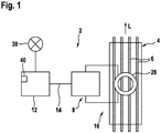
- the device 2 for determining a Ablegereifewerts for one of a support belt 4 with embedded, electrically conductive cord ropes 6 is shown.
- the device 2 may also be referred to as a measuring device 2. In the following, however, the device 2 will only be referred to as such for a short time.
- the tensile strength of cord ropes 6 in support strap 4, especially for elevator systems, often decreases over the life of the support belt 4. This is caused in particular by the tensile load when using the support belt 4.
- the cord ropes 6 may have a plurality of filaments 34. Each filament 34 is also formed in the manner of a rope. To form a cord 6, the filaments may be twisted.
- the support belt 4 When using the support belt 4 under tensile load, it may cause friction between the filaments 34 of a cord 6. Due to the friction of the filaments 34, the diameter of the individual filaments 34 and / or the respective cord 6 can be smaller. Once a strap 4 no longer meets the desired requirements, in particular the legal requirements, the strap 4 is often replaced. When this condition is reached, however, is in practice difficult to determine reliably.
- the device 2 therefore serves to determine a deviation value.
- the determined Ablegereifewert is compared with a Ablegereifegrenzwert to produce an exchange signal when the determined Ablegereifewert is greater than or equal to the predetermined Ablegereifegrenzwert.
- the replacement signal may then represent an exchange state of the support belt 4. In this case, replace the strap 4 or replace it with a new one.
- the Eddy current sensor 8 is designed to generate an electromagnetic alternating field 10.
- the eddy current sensor 8 may have a coil 26.
- the coil 26 is shown schematically.
- the alternating electromagnetic field 10 can be generated.
- the eddy current sensor 8 and in particular the associated coil 26 is or are designed to be arranged in a predetermined measuring arrangement 16 to the carrying belt 4. This is purely exemplary in the FIG. 4 shown.
- the coil 26 of the eddy current sensor 8 is arranged in the predetermined measuring arrangement 16 to the support belt 4, so that the generated by the eddy current sensor 8 and the associated coil 26, alternating electromagnetic field 10 acting on the electrically conductive cord ropes 6 of the support belt 4.
- the alternating field 10 therefore induces eddy currents in the electrically conductive cord ropes 6.
- This causes a damping of the alternating electromagnetic field 10.
- the eddy current sensor 8 is designed and / or configured to detect the damping of the alternating field 10.
- the damping of the alternating field 10 depends on structural and / or geometric properties of the support belt 4, and in particular the associated, electrically conductive cord ropes 6 from.
- the damping of the alternating field 10 depends on the diameters 22 of the cord ropes 6.
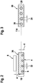
- the damping of the alternating field 10 can depend on the arrangement 18 of the cord ropes 6 in the carrying belt 4. In this context, the synopsis of the FIGS. 2 and 3 directed.
- a reference support belt 28 is shown in a schematic cross-sectional view.
- the reference support belt 28 is intended to correspond to the support belt 4 in the state in which it was originally produced and / or as new.
- the associated electrically conductive reference cord ropes 30 in a height direction H, transverse to the longitudinal direction L of the reference support belt 28th is aligned, at least arranged substantially centrally.
- Each of the reference cord ropes 30 has a reference diameter 24.
- FIG. 6 shows the cross section of a single Referenzcordseils 30. From the FIG. 6 It will also be appreciated that a reference cord 30 may be constructed and / or formed, for example, from a plurality of associated filaments 32, which may be referred to as reference filaments 32.
- the associated cord ropes 6 may be exposed to a corresponding tensile load.
- the individual filaments 34 of each cord 6 rub against each other by the tensile loads, in particular by alternating tensile loads, resulting in a reduction of the diameter 22 of the associated cord 6.
- the cord 6 immediately after manufacture for example, designed as in FIG. 6 is shown, the cord 6 can go through the tensile load after some time a geometric change, so that the cord 6 is formed in cross-section such as is exemplified in the FIG. 5 is shown. Broad the comparison between the FIGS. 5 and 6 indicates that the outer diameter of the reference diameter 24 to the actual diameter 22 may decrease.
- FIG. 3 Another effect of the burden of the support belt 4 can from the synopsis of FIGS. 2 and 3 be removed.
- the reference support belt 28 is shown in cross section.
- each of the reference cord ropes 30 has the reference diameter 24.
- the Referenzcordseile 30 are arranged centrally in the height direction H. Due to the tensile load can lead to the reduction of the diameter, as explained above. Therefore, the cord ropes 6 of the support belt 4, as shown in the FIG. 2 are shown represented with a smaller diameter 22. Moreover, from the FIG. 2 to recognize that the cord ropes were 6 wandered down in height direction H down.
- the arrangement 18 of the cord ropes 6 in the carrying strap 4 has thus compared to the reference arrangement 20 of Referenzcordseile 30 changed in reference support belt 28.
- the change in the arrangement is determined by the offset V of the cord ropes 6 in the height direction H.
- the eddy current sensor 8 in a predetermined measuring arrangement 16 is shown, arranged to the carrying strap 4.
- the support belt 4 can be moved past the eddy current sensor 8 in a translatory manner.
- the predetermined measuring arrangement 16 can therefore refer to the distance A between a coil 26 of the eddy current sensor 8 and the back 36 of the support belt 4. This distance A should preferably be kept constant.
- the eddy current sensor 8 is configured to generate the sensor signal based on the detected attenuation. If the arrangement of at least one cord falls in the support belt, so that it comes to the offset V, the immediate distance between the eddy current sensor 8 and the cord ropes 6 is increased. This causes a change in the attenuation detected by the eddy current sensor 8.
- the eddy current sensor 8 is adapted to be detected accordingly modified attenuation to generate a corresponding sensor signal. Similarly, it is with the change of the diameter 22 of the cord ropes 6. The reduction of the diameter 22 also leads to an increase in the immediate distance between the cord ropes 6 and the eddy current sensor 8. This also causes a change in the damping. This can be detected by means of the eddy current sensor 8. As a result, the sensor signal correspondingly changes the detected attenuation.
- the eddy current sensor 8 is connected by means of a signal connection 14 with the evaluation unit 12 of the device 2.
- the signal connection 14 is preferably emitted as a signal line.
- the eddy current sensor 8 is designed to transmit the sensor signal, which was generated based on the detected attenuation, to the evaluation unit 12 via the signal connection 14.
- the evaluation unit 12 is thus provided with the information as to whether and to what extent an attenuation of the alternating field 10 is present.
- the sensor signal does not have to represent the damping directly.
- the sensor signal may represent a physical quantity dependent on the attenuation. This is, for example, the distance between the eddy current sensor 8 and cord ropes 6.
- the evaluation unit 12 has stored the information as to how the detected attenuation or the sensor signal has to be when the eddy current sensor 8 detects the reference support belt 28 in the predetermined measuring arrangement 16.
- the evaluation unit 12 may also have stored corresponding values for the arrangement of the reference cord ropes 30 in the reference support belt 28 and / or for reference diameter 24 of the cord ropes 30.
- the evaluation unit 12 is configured to determine a Ablegereifewert for the support strap 6 based on the sensor signal that the evaluation unit 12 has been transmitted from the eddy current sensor 8 via the signal connection 14.
- the Ablegereifewert represents, for example, a change in the arrangement 18 of the cord ropes 6 in the support belt 4 with respect to a predetermined reference arrangement 20 of the cord ropes 30 in Carrying strap 28.
- the laydown value may represent a change in the rope diameter 22 of the cord ropes 6 with respect to predetermined reference diameters 24 for the cord ropes 30.
- the laydown value may represent a change of the cord ropes 6 with respect to an as new arrangement and / or configuration. Therefore, by means of the drop-off value, the device 2 now offers the possibility that a measurable quantity gives information as to whether a carrying strap 4 is to be exchanged or not.
- the evaluation unit 12 may therefore be configured to generate an exchange signal when the determined discard value is greater than or equal to a predetermined discard value, the substitution signal representing an exchange state of the support belt 4.
- the device 2 can output the exchange signal, for example optically or acoustically.
- the device 2 is shown with an optical signal generator 38, in particular a lamp.
- the exchange signal can be output by means of the optical signal transmitter 38.
- the device 2 can have an acoustic output unit, by means of which the exchange signal or a corresponding signal can be output.
- the device 2 has a transmission interface 40.
- the transmission interface 40 is preferably assigned to the evaluation unit 12.
- the transmission interface 40 may be designed for the transmission of the exchange signal and / or a Ablegereifesignals.
- the discard signal represents the discard value.
- an external unit can be transmitted.
- the transmission interface 40 is designed as a wired transmission interface 40 or as a wireless transmission interface 40 or as a radio interface.
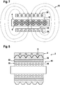
- the electromagnetic alternating field 10 generated by the eddy current sensor 8 is formed in sections as an at least substantially homogeneous electromagnetic alternating field 44. Because in this case, the support belt 4 can be performed in or through the homogeneous, alternating electromagnetic field 44 and cause a corresponding damping of the alternating field 44, without it depends on the distance A between the support belt 4 and the eddy current sensor 8.
- a corresponding, exemplary embodiment is shown in a schematic cross-sectional view in FIG FIG. 7 shown.
- this has an electrical coil 26 which is designed to generate the electromagnetic alternating field 10.
- This coil 26 forms a channel 42 which is open on both sides.
- the channel 42 is designed in such a way that the carrying strap 4 can be guided through the channel 42 in the predetermined measuring arrangement 16 in the belt longitudinal direction L.
- the coil 26 is preferably designed such that from the coil 26 in the channel 42, an at least substantially homogeneous, alternating electric field 44 is generated. This homogeneous, alternating electric field 44 forms part of the total, generated by the coil 26, alternating electromagnetic field 10.
- the at least substantially homogeneous, alternating electric field 44th The damping of the at least substantially homogeneous, alternating electromagnetic field 44 is independent of the distance of the support belt 4 to the coil 26.
- This embodiment therefore offers the advantage that the Ablegereifewert at least substantially only of the diameters 22 and of the changes in the diameter 22 of the cord ropes 6 of the support belt 4 is determined. Measurement inaccuracies in compliance with the predetermined distance A to the eddy current sensor 8 can therefore at least substantially not occur here.
- the Ablegereifewert determinable in this way by means of the evaluation unit 12 is therefore particularly reliable.
- the device 2 has a deflection unit 46.
- the deflection unit 46 is designed for deflecting the support belt 4.
- the deflection unit 46 may have an inner part 48 and a pulley 50 rotatably mounted about and mounted on the inner part.
- the inner part 48 is preferably a cylindrical and / or cylindrical inner part 48.
- the pulley 50 by means of a bearing 52, in particular by means of a sliding bearing, rotatably attached to the inner part 48.
- the pulley 50 can thus rotate about the cylindrical inner part 48 by means of the bearing 52.
- the pulley 50 may have a shape for guiding and / or deflecting the support belt 4.
- the support belt 4, the belt pulley 50 at least partially wrap around.
- the strap 4 is in direct contact on the pulley 50.
- the eddy current sensor 8 has an electrical coil 26 which is designed to generate the electromagnetic alternating field 10 and wherein the electrical coil 26 is received in the inner part 48, in particular integrated, is.
- the coil 26 is thus disposed within the inner part 48.
- this embodiment of the device 2 offers the advantage that the distance between the coil 26 and the electrically conductive cord ropes 6 in the support belt 4 can be kept constant particularly simple. This arrangement therefore offers a particularly interference size robust measuring arrangement.
- At least the radially outer side of the electrical part 26 formed part of the inner part 48 is preferably formed for transmission of the electromagnetic alternating field 10.
- the bearing 52 in particular designed as a plain bearing, and also the pulley 50 are designed for transmission of the alternating electromagnetic field 10. Therefore, the electromagnetic alternating field 10 generated by the coil 26 can penetrate through the inner part 48, the bearing 52 and the pulley 50 to act on the electrically conductive cord ropes 6 of the support belt 4. Here an interaction with the induced eddy current takes place. The corresponding attenuation of the alternating electromagnetic field 10 can be detected by the eddy current sensor 8.
- effects and / or advantages reference is made to the preceding explanations, at least in an analogous manner.
Landscapes
- Engineering & Computer Science (AREA)
- General Engineering & Computer Science (AREA)
- Mechanical Engineering (AREA)
- Chemical & Material Sciences (AREA)
- Analytical Chemistry (AREA)
- Physics & Mathematics (AREA)
- General Physics & Mathematics (AREA)
- Investigating Or Analyzing Materials By The Use Of Magnetic Means (AREA)
- Control Of Conveyors (AREA)
- Measurement Of Length, Angles, Or The Like Using Electric Or Magnetic Means (AREA)
Applications Claiming Priority (1)
| Application Number | Priority Date | Filing Date | Title |
|---|---|---|---|
| DE102017223362.1A DE102017223362A1 (de) | 2017-12-20 | 2017-12-20 | Vorrichtung und Verfahren zur Ermittlung eines Ablegereifewerts für einen Tragriemen mit eingebetteten, elektrisch leitfähigen Cordseilen |
Publications (2)
| Publication Number | Publication Date |
|---|---|
| EP3502013A1 true EP3502013A1 (fr) | 2019-06-26 |
| EP3502013B1 EP3502013B1 (fr) | 2024-04-24 |
Family
ID=63833864
Family Applications (1)
| Application Number | Title | Priority Date | Filing Date |
|---|---|---|---|
| EP18199764.4A Active EP3502013B1 (fr) | 2017-12-20 | 2018-10-11 | Dispositif et procédé de détermination d'une valeur de moment de dépose pour une bandoulière à fils éléctroconducteurs intégrés |
Country Status (2)
| Country | Link |
|---|---|
| EP (1) | EP3502013B1 (fr) |
| DE (1) | DE102017223362A1 (fr) |
Cited By (2)
| Publication number | Priority date | Publication date | Assignee | Title |
|---|---|---|---|---|
| CN114728765A (zh) * | 2019-11-27 | 2022-07-08 | 通力股份公司 | 电梯系统的监控 |
| WO2022188954A1 (fr) * | 2021-03-09 | 2022-09-15 | Kone Corporation | Agencement de surveillance d'état de câble d'appareil de levage |
Citations (2)
| Publication number | Priority date | Publication date | Assignee | Title |
|---|---|---|---|---|
| DE2421623A1 (de) * | 1974-05-04 | 1975-11-13 | Becker Pruente Gmbh | Vorrichtung zum transport von langgestreckten prueflingen durch ein geraet zur zerstoerungsfreien werkstoffpruefung |
| DE19544885A1 (de) * | 1995-12-01 | 1997-06-05 | Arntz Optibelt Kg | Verfahren und Vorrichtung zur Herstellung eines Kunststoff-Kraftübertragungsriemens |
Family Cites Families (1)
| Publication number | Priority date | Publication date | Assignee | Title |
|---|---|---|---|---|
| US8312987B2 (en) * | 2008-01-16 | 2012-11-20 | The Gates Corporation | Belt monitoring systems and methods |
-
2017
- 2017-12-20 DE DE102017223362.1A patent/DE102017223362A1/de active Pending
-
2018
- 2018-10-11 EP EP18199764.4A patent/EP3502013B1/fr active Active
Patent Citations (2)
| Publication number | Priority date | Publication date | Assignee | Title |
|---|---|---|---|---|
| DE2421623A1 (de) * | 1974-05-04 | 1975-11-13 | Becker Pruente Gmbh | Vorrichtung zum transport von langgestreckten prueflingen durch ein geraet zur zerstoerungsfreien werkstoffpruefung |
| DE19544885A1 (de) * | 1995-12-01 | 1997-06-05 | Arntz Optibelt Kg | Verfahren und Vorrichtung zur Herstellung eines Kunststoff-Kraftübertragungsriemens |
Cited By (2)
| Publication number | Priority date | Publication date | Assignee | Title |
|---|---|---|---|---|
| CN114728765A (zh) * | 2019-11-27 | 2022-07-08 | 通力股份公司 | 电梯系统的监控 |
| WO2022188954A1 (fr) * | 2021-03-09 | 2022-09-15 | Kone Corporation | Agencement de surveillance d'état de câble d'appareil de levage |
Also Published As
| Publication number | Publication date |
|---|---|
| DE102017223362A1 (de) | 2019-06-27 |
| EP3502013B1 (fr) | 2024-04-24 |
Similar Documents
| Publication | Publication Date | Title |
|---|---|---|
| EP2383566B1 (fr) | Procédé et système pour tester des câbles | |
| DE102007028965A1 (de) | Verfahren zur Überprüfung des Stromflusses durch Einzeldrähte eines Litzendrahtes sowie Vorrichtung zur Durchführung des Verfahrens | |
| EP2702387A2 (fr) | Banc d'essai de câbles | |
| EP4314756B1 (fr) | Dispositif et procédé de détermination d'une extension longitudinale et de la vitesse moyenne d'une courroie, et de détermination de la vitesse d'au moins une poulie à courroie | |
| EP2794448A1 (fr) | Installation d'ascenseur | |
| EP3623748B1 (fr) | Système pour déterminer l'allongement longitudinal d'une courroie | |
| DE202011001846U1 (de) | Vorrichtung zur Erkennung der Ablegereife eines hochfesten Faserseils beim Einsatz an Hebezeugen | |
| EP2935071A1 (fr) | Installation d'ascenseur pourvue d'un dispositif de surveillance et procédé de surveillance d'une installation d'ascenseur | |
| WO2017153250A1 (fr) | Elément de support pour installation d'ascenseur, comportant plusieurs détecteurs disposés le long du moyen de support | |
| DE202019104826U1 (de) | Vorrichtung umfassend eine Energieführungskette und eine Gleitauflage | |
| EP3502013B1 (fr) | Dispositif et procédé de détermination d'une valeur de moment de dépose pour une bandoulière à fils éléctroconducteurs intégrés | |
| EP3839462B1 (fr) | Ceinture dentée avec capteur intégré | |
| EP3191641A2 (fr) | Câble de fibres | |
| WO2022156848A1 (fr) | Dispositif et procédé de détermination d'une dilatation linéaire d'une courroie | |
| WO2019057352A1 (fr) | Système d'entraînement pour un système d'ascenseur ainsi que système d'ascenseur | |
| EP3620781A1 (fr) | Procédé de détection d'un état d'usure d'une bretelle | |
| DE3822466A1 (de) | Verfahren zur kontrolle von lage und bewegung seilbewegter transporteinrichtungen | |
| DE202010006145U1 (de) | System zur Prüfung von Seilen | |
| DE10085343B4 (de) | Spannungskontrolle in einer Maschine zur Herstellung von Seilen | |
| EP3598096A1 (fr) | Courroie et système | |
| EP3042874B1 (fr) | Surveillance de courroie d'ascenseur | |
| EP3628631B1 (fr) | Procédé de détection de l'état des moyens porteurs | |
| EP3391018A1 (fr) | Procédé de détermination de l'état d'usure nécessitant le remplacement d'un câble constitué de matériau fibreux textile | |
| DE102017222348A1 (de) | Verfahren und Einrichtung zum Prüfen eines langgestreckten Tragmittels für Aufzüge sowie ein solches Tragmittel | |
| EP4408783A1 (fr) | Procédé de vérification de l'état d'usure, en particulier pour prédire la durée de vie restante et/ou la durée de fonctionnement restante, d'au moins un ruban mobile d'un dispositif qui utilise ledit ruban mobile pour son utilisation prévue, dispositif et produit-programme informatique |
Legal Events
| Date | Code | Title | Description |
|---|---|---|---|
| PUAI | Public reference made under article 153(3) epc to a published international application that has entered the european phase |
Free format text: ORIGINAL CODE: 0009012 |
|
| STAA | Information on the status of an ep patent application or granted ep patent |
Free format text: STATUS: THE APPLICATION HAS BEEN PUBLISHED |
|
| AK | Designated contracting states |
Kind code of ref document: A1 Designated state(s): AL AT BE BG CH CY CZ DE DK EE ES FI FR GB GR HR HU IE IS IT LI LT LU LV MC MK MT NL NO PL PT RO RS SE SI SK SM TR |
|
| AX | Request for extension of the european patent |
Extension state: BA ME |
|
| STAA | Information on the status of an ep patent application or granted ep patent |
Free format text: STATUS: REQUEST FOR EXAMINATION WAS MADE |
|
| 17P | Request for examination filed |
Effective date: 20200102 |
|
| RBV | Designated contracting states (corrected) |
Designated state(s): AL AT BE BG CH CY CZ DE DK EE ES FI FR GB GR HR HU IE IS IT LI LT LU LV MC MK MT NL NO PL PT RO RS SE SI SK SM TR |
|
| STAA | Information on the status of an ep patent application or granted ep patent |
Free format text: STATUS: EXAMINATION IS IN PROGRESS |
|
| 17Q | First examination report despatched |
Effective date: 20200406 |
|
| GRAP | Despatch of communication of intention to grant a patent |
Free format text: ORIGINAL CODE: EPIDOSNIGR1 |
|
| STAA | Information on the status of an ep patent application or granted ep patent |
Free format text: STATUS: GRANT OF PATENT IS INTENDED |
|
| INTG | Intention to grant announced |
Effective date: 20231115 |
|
| P01 | Opt-out of the competence of the unified patent court (upc) registered |
Effective date: 20240117 |
|
| GRAS | Grant fee paid |
Free format text: ORIGINAL CODE: EPIDOSNIGR3 |
|
| GRAA | (expected) grant |
Free format text: ORIGINAL CODE: 0009210 |
|
| STAA | Information on the status of an ep patent application or granted ep patent |
Free format text: STATUS: THE PATENT HAS BEEN GRANTED |
|
| RAP1 | Party data changed (applicant data changed or rights of an application transferred) |
Owner name: CONTITECH DEUTSCHLAND GMBH |
|
| AK | Designated contracting states |
Kind code of ref document: B1 Designated state(s): AL AT BE BG CH CY CZ DE DK EE ES FI FR GB GR HR HU IE IS IT LI LT LU LV MC MK MT NL NO PL PT RO RS SE SI SK SM TR |
|
| REG | Reference to a national code |
Ref country code: GB Ref legal event code: FG4D Free format text: NOT ENGLISH |
|
| REG | Reference to a national code |
Ref country code: CH Ref legal event code: EP |
|
| REG | Reference to a national code |
Ref country code: DE Ref legal event code: R096 Ref document number: 502018014477 Country of ref document: DE |
|
| REG | Reference to a national code |
Ref country code: IE Ref legal event code: FG4D Free format text: LANGUAGE OF EP DOCUMENT: GERMAN |
|
| REG | Reference to a national code |
Ref country code: LT Ref legal event code: MG9D |
|
| REG | Reference to a national code |
Ref country code: NL Ref legal event code: MP Effective date: 20240424 |
|
| PG25 | Lapsed in a contracting state [announced via postgrant information from national office to epo] |
Ref country code: NL Free format text: LAPSE BECAUSE OF FAILURE TO SUBMIT A TRANSLATION OF THE DESCRIPTION OR TO PAY THE FEE WITHIN THE PRESCRIBED TIME-LIMIT Effective date: 20240424 |
|
| PG25 | Lapsed in a contracting state [announced via postgrant information from national office to epo] |
Ref country code: NL Free format text: LAPSE BECAUSE OF FAILURE TO SUBMIT A TRANSLATION OF THE DESCRIPTION OR TO PAY THE FEE WITHIN THE PRESCRIBED TIME-LIMIT Effective date: 20240424 |
|
| PG25 | Lapsed in a contracting state [announced via postgrant information from national office to epo] |
Ref country code: IS Free format text: LAPSE BECAUSE OF FAILURE TO SUBMIT A TRANSLATION OF THE DESCRIPTION OR TO PAY THE FEE WITHIN THE PRESCRIBED TIME-LIMIT Effective date: 20240824 |
|
| PG25 | Lapsed in a contracting state [announced via postgrant information from national office to epo] |
Ref country code: BG Free format text: LAPSE BECAUSE OF FAILURE TO SUBMIT A TRANSLATION OF THE DESCRIPTION OR TO PAY THE FEE WITHIN THE PRESCRIBED TIME-LIMIT Effective date: 20240424 |
|
| PG25 | Lapsed in a contracting state [announced via postgrant information from national office to epo] |
Ref country code: HR Free format text: LAPSE BECAUSE OF FAILURE TO SUBMIT A TRANSLATION OF THE DESCRIPTION OR TO PAY THE FEE WITHIN THE PRESCRIBED TIME-LIMIT Effective date: 20240424 Ref country code: FI Free format text: LAPSE BECAUSE OF FAILURE TO SUBMIT A TRANSLATION OF THE DESCRIPTION OR TO PAY THE FEE WITHIN THE PRESCRIBED TIME-LIMIT Effective date: 20240424 |
|
| PG25 | Lapsed in a contracting state [announced via postgrant information from national office to epo] |
Ref country code: GR Free format text: LAPSE BECAUSE OF FAILURE TO SUBMIT A TRANSLATION OF THE DESCRIPTION OR TO PAY THE FEE WITHIN THE PRESCRIBED TIME-LIMIT Effective date: 20240725 |
|
| PG25 | Lapsed in a contracting state [announced via postgrant information from national office to epo] |
Ref country code: PT Free format text: LAPSE BECAUSE OF FAILURE TO SUBMIT A TRANSLATION OF THE DESCRIPTION OR TO PAY THE FEE WITHIN THE PRESCRIBED TIME-LIMIT Effective date: 20240826 |
|
| PG25 | Lapsed in a contracting state [announced via postgrant information from national office to epo] |
Ref country code: ES Free format text: LAPSE BECAUSE OF FAILURE TO SUBMIT A TRANSLATION OF THE DESCRIPTION OR TO PAY THE FEE WITHIN THE PRESCRIBED TIME-LIMIT Effective date: 20240424 |
|
| PG25 | Lapsed in a contracting state [announced via postgrant information from national office to epo] |
Ref country code: PL Free format text: LAPSE BECAUSE OF FAILURE TO SUBMIT A TRANSLATION OF THE DESCRIPTION OR TO PAY THE FEE WITHIN THE PRESCRIBED TIME-LIMIT Effective date: 20240424 |
|
| PG25 | Lapsed in a contracting state [announced via postgrant information from national office to epo] |
Ref country code: LV Free format text: LAPSE BECAUSE OF FAILURE TO SUBMIT A TRANSLATION OF THE DESCRIPTION OR TO PAY THE FEE WITHIN THE PRESCRIBED TIME-LIMIT Effective date: 20240424 |
|
| PG25 | Lapsed in a contracting state [announced via postgrant information from national office to epo] |
Ref country code: PT Free format text: LAPSE BECAUSE OF FAILURE TO SUBMIT A TRANSLATION OF THE DESCRIPTION OR TO PAY THE FEE WITHIN THE PRESCRIBED TIME-LIMIT Effective date: 20240826 Ref country code: PL Free format text: LAPSE BECAUSE OF FAILURE TO SUBMIT A TRANSLATION OF THE DESCRIPTION OR TO PAY THE FEE WITHIN THE PRESCRIBED TIME-LIMIT Effective date: 20240424 Ref country code: NO Free format text: LAPSE BECAUSE OF FAILURE TO SUBMIT A TRANSLATION OF THE DESCRIPTION OR TO PAY THE FEE WITHIN THE PRESCRIBED TIME-LIMIT Effective date: 20240724 Ref country code: LV Free format text: LAPSE BECAUSE OF FAILURE TO SUBMIT A TRANSLATION OF THE DESCRIPTION OR TO PAY THE FEE WITHIN THE PRESCRIBED TIME-LIMIT Effective date: 20240424 Ref country code: IS Free format text: LAPSE BECAUSE OF FAILURE TO SUBMIT A TRANSLATION OF THE DESCRIPTION OR TO PAY THE FEE WITHIN THE PRESCRIBED TIME-LIMIT Effective date: 20240824 Ref country code: HR Free format text: LAPSE BECAUSE OF FAILURE TO SUBMIT A TRANSLATION OF THE DESCRIPTION OR TO PAY THE FEE WITHIN THE PRESCRIBED TIME-LIMIT Effective date: 20240424 Ref country code: GR Free format text: LAPSE BECAUSE OF FAILURE TO SUBMIT A TRANSLATION OF THE DESCRIPTION OR TO PAY THE FEE WITHIN THE PRESCRIBED TIME-LIMIT Effective date: 20240725 Ref country code: FI Free format text: LAPSE BECAUSE OF FAILURE TO SUBMIT A TRANSLATION OF THE DESCRIPTION OR TO PAY THE FEE WITHIN THE PRESCRIBED TIME-LIMIT Effective date: 20240424 Ref country code: ES Free format text: LAPSE BECAUSE OF FAILURE TO SUBMIT A TRANSLATION OF THE DESCRIPTION OR TO PAY THE FEE WITHIN THE PRESCRIBED TIME-LIMIT Effective date: 20240424 Ref country code: BG Free format text: LAPSE BECAUSE OF FAILURE TO SUBMIT A TRANSLATION OF THE DESCRIPTION OR TO PAY THE FEE WITHIN THE PRESCRIBED TIME-LIMIT Effective date: 20240424 Ref country code: RS Free format text: LAPSE BECAUSE OF FAILURE TO SUBMIT A TRANSLATION OF THE DESCRIPTION OR TO PAY THE FEE WITHIN THE PRESCRIBED TIME-LIMIT Effective date: 20240724 |
|
| PG25 | Lapsed in a contracting state [announced via postgrant information from national office to epo] |
Ref country code: DK Free format text: LAPSE BECAUSE OF FAILURE TO SUBMIT A TRANSLATION OF THE DESCRIPTION OR TO PAY THE FEE WITHIN THE PRESCRIBED TIME-LIMIT Effective date: 20240424 |
|
| PG25 | Lapsed in a contracting state [announced via postgrant information from national office to epo] |
Ref country code: EE Free format text: LAPSE BECAUSE OF FAILURE TO SUBMIT A TRANSLATION OF THE DESCRIPTION OR TO PAY THE FEE WITHIN THE PRESCRIBED TIME-LIMIT Effective date: 20240424 |
|
| PG25 | Lapsed in a contracting state [announced via postgrant information from national office to epo] |
Ref country code: CZ Free format text: LAPSE BECAUSE OF FAILURE TO SUBMIT A TRANSLATION OF THE DESCRIPTION OR TO PAY THE FEE WITHIN THE PRESCRIBED TIME-LIMIT Effective date: 20240424 |
|
| PG25 | Lapsed in a contracting state [announced via postgrant information from national office to epo] |
Ref country code: SK Free format text: LAPSE BECAUSE OF FAILURE TO SUBMIT A TRANSLATION OF THE DESCRIPTION OR TO PAY THE FEE WITHIN THE PRESCRIBED TIME-LIMIT Effective date: 20240424 Ref country code: RO Free format text: LAPSE BECAUSE OF FAILURE TO SUBMIT A TRANSLATION OF THE DESCRIPTION OR TO PAY THE FEE WITHIN THE PRESCRIBED TIME-LIMIT Effective date: 20240424 |
|
| REG | Reference to a national code |
Ref country code: DE Ref legal event code: R097 Ref document number: 502018014477 Country of ref document: DE |
|
| PG25 | Lapsed in a contracting state [announced via postgrant information from national office to epo] |
Ref country code: SM Free format text: LAPSE BECAUSE OF FAILURE TO SUBMIT A TRANSLATION OF THE DESCRIPTION OR TO PAY THE FEE WITHIN THE PRESCRIBED TIME-LIMIT Effective date: 20240424 |
|
| PG25 | Lapsed in a contracting state [announced via postgrant information from national office to epo] |
Ref country code: SM Free format text: LAPSE BECAUSE OF FAILURE TO SUBMIT A TRANSLATION OF THE DESCRIPTION OR TO PAY THE FEE WITHIN THE PRESCRIBED TIME-LIMIT Effective date: 20240424 Ref country code: SK Free format text: LAPSE BECAUSE OF FAILURE TO SUBMIT A TRANSLATION OF THE DESCRIPTION OR TO PAY THE FEE WITHIN THE PRESCRIBED TIME-LIMIT Effective date: 20240424 Ref country code: RO Free format text: LAPSE BECAUSE OF FAILURE TO SUBMIT A TRANSLATION OF THE DESCRIPTION OR TO PAY THE FEE WITHIN THE PRESCRIBED TIME-LIMIT Effective date: 20240424 Ref country code: EE Free format text: LAPSE BECAUSE OF FAILURE TO SUBMIT A TRANSLATION OF THE DESCRIPTION OR TO PAY THE FEE WITHIN THE PRESCRIBED TIME-LIMIT Effective date: 20240424 Ref country code: DK Free format text: LAPSE BECAUSE OF FAILURE TO SUBMIT A TRANSLATION OF THE DESCRIPTION OR TO PAY THE FEE WITHIN THE PRESCRIBED TIME-LIMIT Effective date: 20240424 Ref country code: CZ Free format text: LAPSE BECAUSE OF FAILURE TO SUBMIT A TRANSLATION OF THE DESCRIPTION OR TO PAY THE FEE WITHIN THE PRESCRIBED TIME-LIMIT Effective date: 20240424 |
|
| PLBE | No opposition filed within time limit |
Free format text: ORIGINAL CODE: 0009261 |
|
| STAA | Information on the status of an ep patent application or granted ep patent |
Free format text: STATUS: NO OPPOSITION FILED WITHIN TIME LIMIT |
|
| 26N | No opposition filed |
Effective date: 20250127 |
|
| PG25 | Lapsed in a contracting state [announced via postgrant information from national office to epo] |
Ref country code: SI Free format text: LAPSE BECAUSE OF FAILURE TO SUBMIT A TRANSLATION OF THE DESCRIPTION OR TO PAY THE FEE WITHIN THE PRESCRIBED TIME-LIMIT Effective date: 20240424 |
|
| REG | Reference to a national code |
Ref country code: CH Ref legal event code: PL |
|
| PG25 | Lapsed in a contracting state [announced via postgrant information from national office to epo] |
Ref country code: MC Free format text: LAPSE BECAUSE OF FAILURE TO SUBMIT A TRANSLATION OF THE DESCRIPTION OR TO PAY THE FEE WITHIN THE PRESCRIBED TIME-LIMIT Effective date: 20240424 |
|
| PG25 | Lapsed in a contracting state [announced via postgrant information from national office to epo] |
Ref country code: LU Free format text: LAPSE BECAUSE OF NON-PAYMENT OF DUE FEES Effective date: 20241011 Ref country code: BE Free format text: LAPSE BECAUSE OF NON-PAYMENT OF DUE FEES Effective date: 20241031 |
|
| PG25 | Lapsed in a contracting state [announced via postgrant information from national office to epo] |
Ref country code: CH Free format text: LAPSE BECAUSE OF NON-PAYMENT OF DUE FEES Effective date: 20241031 |
|
| REG | Reference to a national code |
Ref country code: BE Ref legal event code: MM Effective date: 20241031 |
|
| PG25 | Lapsed in a contracting state [announced via postgrant information from national office to epo] |
Ref country code: SE Free format text: LAPSE BECAUSE OF FAILURE TO SUBMIT A TRANSLATION OF THE DESCRIPTION OR TO PAY THE FEE WITHIN THE PRESCRIBED TIME-LIMIT Effective date: 20240424 |
|
| PG25 | Lapsed in a contracting state [announced via postgrant information from national office to epo] |
Ref country code: IE Free format text: LAPSE BECAUSE OF NON-PAYMENT OF DUE FEES Effective date: 20241011 |
|
| REG | Reference to a national code |
Ref country code: AT Ref legal event code: MM01 Ref document number: 1679397 Country of ref document: AT Kind code of ref document: T Effective date: 20241011 |
|
| PGFP | Annual fee paid to national office [announced via postgrant information from national office to epo] |
Ref country code: DE Payment date: 20251031 Year of fee payment: 8 |
|
| PGFP | Annual fee paid to national office [announced via postgrant information from national office to epo] |
Ref country code: GB Payment date: 20251022 Year of fee payment: 8 |
|
| PG25 | Lapsed in a contracting state [announced via postgrant information from national office to epo] |
Ref country code: AT Free format text: LAPSE BECAUSE OF NON-PAYMENT OF DUE FEES Effective date: 20241011 |
|
| PGFP | Annual fee paid to national office [announced via postgrant information from national office to epo] |
Ref country code: FR Payment date: 20251030 Year of fee payment: 8 |
|
| PG25 | Lapsed in a contracting state [announced via postgrant information from national office to epo] |
Ref country code: CY Free format text: LAPSE BECAUSE OF FAILURE TO SUBMIT A TRANSLATION OF THE DESCRIPTION OR TO PAY THE FEE WITHIN THE PRESCRIBED TIME-LIMIT; INVALID AB INITIO Effective date: 20181011 Ref country code: IT Free format text: LAPSE BECAUSE OF FAILURE TO SUBMIT A TRANSLATION OF THE DESCRIPTION OR TO PAY THE FEE WITHIN THE PRESCRIBED TIME-LIMIT Effective date: 20240424 |
|
| PG25 | Lapsed in a contracting state [announced via postgrant information from national office to epo] |
Ref country code: HU Free format text: LAPSE BECAUSE OF FAILURE TO SUBMIT A TRANSLATION OF THE DESCRIPTION OR TO PAY THE FEE WITHIN THE PRESCRIBED TIME-LIMIT; INVALID AB INITIO Effective date: 20181011 |