EP3519155B1 - Verfahren zum verarbeiten von folien sowie eine vorschubeinrichtung - Google Patents
Verfahren zum verarbeiten von folien sowie eine vorschubeinrichtung Download PDFInfo
- Publication number
- EP3519155B1 EP3519155B1 EP17780672.6A EP17780672A EP3519155B1 EP 3519155 B1 EP3519155 B1 EP 3519155B1 EP 17780672 A EP17780672 A EP 17780672A EP 3519155 B1 EP3519155 B1 EP 3519155B1
- Authority
- EP
- European Patent Office
- Prior art keywords
- film
- film webs
- motif
- webs
- feed
- Prior art date
- Legal status (The legal status is an assumption and is not a legal conclusion. Google has not performed a legal analysis and makes no representation as to the accuracy of the status listed.)
- Active
Links
Images


Classifications
-
- B—PERFORMING OPERATIONS; TRANSPORTING
- B29—WORKING OF PLASTICS; WORKING OF SUBSTANCES IN A PLASTIC STATE IN GENERAL
- B29C—SHAPING OR JOINING OF PLASTICS; SHAPING OF MATERIAL IN A PLASTIC STATE, NOT OTHERWISE PROVIDED FOR; AFTER-TREATMENT OF THE SHAPED PRODUCTS, e.g. REPAIRING
- B29C45/00—Injection moulding, i.e. forcing the required volume of moulding material through a nozzle into a closed mould; Apparatus therefor
- B29C45/14—Injection moulding, i.e. forcing the required volume of moulding material through a nozzle into a closed mould; Apparatus therefor incorporating preformed parts or layers, e.g. injection moulding around inserts or for coating articles
- B29C45/14008—Inserting articles into the mould
- B29C45/14016—Intermittently feeding endless articles, e.g. transfer films, to the mould
-
- B—PERFORMING OPERATIONS; TRANSPORTING
- B29—WORKING OF PLASTICS; WORKING OF SUBSTANCES IN A PLASTIC STATE IN GENERAL
- B29C—SHAPING OR JOINING OF PLASTICS; SHAPING OF MATERIAL IN A PLASTIC STATE, NOT OTHERWISE PROVIDED FOR; AFTER-TREATMENT OF THE SHAPED PRODUCTS, e.g. REPAIRING
- B29C45/00—Injection moulding, i.e. forcing the required volume of moulding material through a nozzle into a closed mould; Apparatus therefor
- B29C45/17—Component parts, details or accessories; Auxiliary operations
- B29C45/76—Measuring, controlling or regulating
-
- B—PERFORMING OPERATIONS; TRANSPORTING
- B29—WORKING OF PLASTICS; WORKING OF SUBSTANCES IN A PLASTIC STATE IN GENERAL
- B29C—SHAPING OR JOINING OF PLASTICS; SHAPING OF MATERIAL IN A PLASTIC STATE, NOT OTHERWISE PROVIDED FOR; AFTER-TREATMENT OF THE SHAPED PRODUCTS, e.g. REPAIRING
- B29C45/00—Injection moulding, i.e. forcing the required volume of moulding material through a nozzle into a closed mould; Apparatus therefor
- B29C45/14—Injection moulding, i.e. forcing the required volume of moulding material through a nozzle into a closed mould; Apparatus therefor incorporating preformed parts or layers, e.g. injection moulding around inserts or for coating articles
- B29C2045/1486—Details, accessories and auxiliary operations
- B29C2045/14901—Coating a sheet-like insert smaller than the dimensions of the adjacent mould wall
- B29C2045/14918—Coating a sheet-like insert smaller than the dimensions of the adjacent mould wall in-mould-labelling
-
- B—PERFORMING OPERATIONS; TRANSPORTING
- B29—WORKING OF PLASTICS; WORKING OF SUBSTANCES IN A PLASTIC STATE IN GENERAL
- B29C—SHAPING OR JOINING OF PLASTICS; SHAPING OF MATERIAL IN A PLASTIC STATE, NOT OTHERWISE PROVIDED FOR; AFTER-TREATMENT OF THE SHAPED PRODUCTS, e.g. REPAIRING
- B29C45/00—Injection moulding, i.e. forcing the required volume of moulding material through a nozzle into a closed mould; Apparatus therefor
- B29C45/17—Component parts, details or accessories; Auxiliary operations
- B29C45/26—Moulds
- B29C2045/2683—Plurality of independent mould cavities in a single mould
-
- B—PERFORMING OPERATIONS; TRANSPORTING
- B29—WORKING OF PLASTICS; WORKING OF SUBSTANCES IN A PLASTIC STATE IN GENERAL
- B29C—SHAPING OR JOINING OF PLASTICS; SHAPING OF MATERIAL IN A PLASTIC STATE, NOT OTHERWISE PROVIDED FOR; AFTER-TREATMENT OF THE SHAPED PRODUCTS, e.g. REPAIRING
- B29C2945/00—Indexing scheme relating to injection moulding, i.e. forcing the required volume of moulding material through a nozzle into a closed mould
- B29C2945/76—Measuring, controlling or regulating
- B29C2945/76003—Measured parameter
- B29C2945/76083—Position
-
- B—PERFORMING OPERATIONS; TRANSPORTING
- B29—WORKING OF PLASTICS; WORKING OF SUBSTANCES IN A PLASTIC STATE IN GENERAL
- B29C—SHAPING OR JOINING OF PLASTICS; SHAPING OF MATERIAL IN A PLASTIC STATE, NOT OTHERWISE PROVIDED FOR; AFTER-TREATMENT OF THE SHAPED PRODUCTS, e.g. REPAIRING
- B29C2945/00—Indexing scheme relating to injection moulding, i.e. forcing the required volume of moulding material through a nozzle into a closed mould
- B29C2945/76—Measuring, controlling or regulating
- B29C2945/76003—Measured parameter
- B29C2945/76167—Presence, absence of objects
-
- B—PERFORMING OPERATIONS; TRANSPORTING
- B29—WORKING OF PLASTICS; WORKING OF SUBSTANCES IN A PLASTIC STATE IN GENERAL
- B29C—SHAPING OR JOINING OF PLASTICS; SHAPING OF MATERIAL IN A PLASTIC STATE, NOT OTHERWISE PROVIDED FOR; AFTER-TREATMENT OF THE SHAPED PRODUCTS, e.g. REPAIRING
- B29C2945/00—Indexing scheme relating to injection moulding, i.e. forcing the required volume of moulding material through a nozzle into a closed mould
- B29C2945/76—Measuring, controlling or regulating
- B29C2945/76177—Location of measurement
- B29C2945/76294—Inserts
-
- B—PERFORMING OPERATIONS; TRANSPORTING
- B29—WORKING OF PLASTICS; WORKING OF SUBSTANCES IN A PLASTIC STATE IN GENERAL
- B29C—SHAPING OR JOINING OF PLASTICS; SHAPING OF MATERIAL IN A PLASTIC STATE, NOT OTHERWISE PROVIDED FOR; AFTER-TREATMENT OF THE SHAPED PRODUCTS, e.g. REPAIRING
- B29C2945/00—Indexing scheme relating to injection moulding, i.e. forcing the required volume of moulding material through a nozzle into a closed mould
- B29C2945/76—Measuring, controlling or regulating
- B29C2945/76451—Measurement means
- B29C2945/76461—Optical, e.g. laser
-
- B—PERFORMING OPERATIONS; TRANSPORTING
- B29—WORKING OF PLASTICS; WORKING OF SUBSTANCES IN A PLASTIC STATE IN GENERAL
- B29C—SHAPING OR JOINING OF PLASTICS; SHAPING OF MATERIAL IN A PLASTIC STATE, NOT OTHERWISE PROVIDED FOR; AFTER-TREATMENT OF THE SHAPED PRODUCTS, e.g. REPAIRING
- B29C2945/00—Indexing scheme relating to injection moulding, i.e. forcing the required volume of moulding material through a nozzle into a closed mould
- B29C2945/76—Measuring, controlling or regulating
- B29C2945/76494—Controlled parameter
- B29C2945/76545—Flow rate
-
- B—PERFORMING OPERATIONS; TRANSPORTING
- B29—WORKING OF PLASTICS; WORKING OF SUBSTANCES IN A PLASTIC STATE IN GENERAL
- B29C—SHAPING OR JOINING OF PLASTICS; SHAPING OF MATERIAL IN A PLASTIC STATE, NOT OTHERWISE PROVIDED FOR; AFTER-TREATMENT OF THE SHAPED PRODUCTS, e.g. REPAIRING
- B29C2945/00—Indexing scheme relating to injection moulding, i.e. forcing the required volume of moulding material through a nozzle into a closed mould
- B29C2945/76—Measuring, controlling or regulating
- B29C2945/76494—Controlled parameter
- B29C2945/76568—Position
-
- B—PERFORMING OPERATIONS; TRANSPORTING
- B29—WORKING OF PLASTICS; WORKING OF SUBSTANCES IN A PLASTIC STATE IN GENERAL
- B29C—SHAPING OR JOINING OF PLASTICS; SHAPING OF MATERIAL IN A PLASTIC STATE, NOT OTHERWISE PROVIDED FOR; AFTER-TREATMENT OF THE SHAPED PRODUCTS, e.g. REPAIRING
- B29C2945/00—Indexing scheme relating to injection moulding, i.e. forcing the required volume of moulding material through a nozzle into a closed mould
- B29C2945/76—Measuring, controlling or regulating
- B29C2945/76655—Location of control
- B29C2945/76772—Inserts
-
- B—PERFORMING OPERATIONS; TRANSPORTING
- B29—WORKING OF PLASTICS; WORKING OF SUBSTANCES IN A PLASTIC STATE IN GENERAL
- B29L—INDEXING SCHEME ASSOCIATED WITH SUBCLASS B29C, RELATING TO PARTICULAR ARTICLES
- B29L2031/00—Other particular articles
- B29L2031/30—Vehicles, e.g. ships or aircraft, or body parts thereof
- B29L2031/3005—Body finishings
Definitions
- the invention relates to a method for processing foils, in particular IMD foils, as well as a feed device, an injection molding tool and a system.
- plastic films or layers that can be transferred from a carrier film are used.
- Plastic parts decorated in this way are used, for example, in automobile construction for automobile interior parts such as door strips, strips in instrument panels and center console panels, in entertainment electronics for decorative strips on televisions or in telecommunications for housing shells for portable devices such as cell phones.
- IMD In-Mold Decoration
- a plastic film is inserted into a cavity of a mold and then back-injected with an initially flowable filling medium. The film is usually automatically fed into the Tool shape transported. After the back injection, the carrier film can be peeled off from the layers transferred onto the solidified filling medium.
- JP 62128720 A discloses an IMD film which is fed into an injection mold by means of a feed device.
- the IMD film is also positioned correctly in relation to the injection mold via sensors and position markings on the IMD film, before the injection mold is closed and the IMD film is back-injected with the hot plastic injection compound.
- the JP H106358 A relates to a method for processing two film webs by means of a feed device and an injection molding tool.
- This object is achieved by a method for processing film webs, in particular IMD film webs, according to one of Claims 1 to 10.
- the direction of feed is understood here to mean the direction in which the film webs are from the film unwinders in the direction of the film winder be guided. It is possible, for example, for the film unwinders and the film winder to be arranged in a plane spanned by an x and y coordinate, so that the film webs running between the film unwinders and film winder particularly run along the y axis. For example, it is possible that the film webs are advanced from top to bottom, ie in particular that the direction of advance runs perpendicularly, or that the film webs are advanced from right to left or from left to right, ie in particular that the direction of advance runs horizontally.
- essentially perpendicular is understood to mean an angle range between 80 ° and 100 °, preferably between 85 ° and 95 °, in particular 90 °.
- a top view is understood here to mean a top view of the two film webs arranged next to one another. It is thus possible for the top view to take place from the surface normal, that is to say a direction perpendicular to a plane spanned by the two film webs arranged next to one another and / or in the closing and opening directions of the injection molding tool. For example, if the two film webs arranged next to one another lie in a plane spanned by an x and y coordinate, the direction of the top view is a z direction perpendicular to the plane spanned by the x and y coordinate.
- a motif can be, for example, a graphically designed outline, a figurative representation, an image, a visually recognizable design element, a symbol, a logo, a portrait, a pattern, an alphanumeric character, a text, a color design and the like.
- the film webs are preferably designed in such a way that the motifs are each surrounded by a motif-free area.
- the motif-free area is formed between the motifs and the side edges of the film webs and / or between the motifs.
- the motif-free area therefore preferably forms a frame, in particular a surrounding frame, around a respective motif.
- the width of the motif-free area is preferably between 10 mm and 550 mm, in particular between 25 mm and 300 mm.
- the motif-free area preferably has a first partial area and a second partial area, the first partial area in particular forming space for the positioning of a clamping device, in particular a clamping frame, and / or the second partial area forming space for the positioning of register marks.
- the first sub-area is arranged directly adjacent to the motif, in particular that the first sub-area is arranged directly adjacent to the motif in order to fix the film webs by means of a clamping device in the immediate vicinity of the motif, so that disruptive factors such as film expansions, Wrinkles etc. can be minimized.
- the second sub-area and the motif are preferably arranged at a distance from one another.
- the first sub-area lies between the motif and the second sub-area.
- the reverse order is also possible, ie the second partial area for the register marks is arranged directly adjacent to the motif, in particular directly adjacent to the motif, and the first Partial area for fixing the film by means of a clamping device is provided further outside relative thereto.
- the first partial area preferably has a width between 5 mm and 500 mm, particularly preferably between 15 mm and 200 mm.
- the second sub-area preferably has a width between 5 mm and 50 mm, particularly preferably between 15 mm and 30 mm.
- a film web it is also possible for a film web to have different motifs, in particular motifs that follow one another in the feed direction. It is also advantageous that the two film webs arranged next to one another have matching motifs. However, the film webs can also have motifs that differ from one another.
- the motifs can preferably be both individual images and endless motifs.
- the motifs preferably protrude beyond the cavities. It is thus possible for the motifs to be at least 1% larger than the cavities. In particular, the motifs protrude beyond the cavities in every direction, preferably between 1 mm and 20 mm. This slight protrusion of the motifs ensures that little paint or paint is present outside the cavities, so that harmful adhesions and soiling on the injection molding tool can be avoided.
- Accurately fitting or registering is to be understood as a positional accuracy of two or more elements, here in particular the motifs of the film webs and the cavities, with respect to one another.
- the accuracy of fit or register accuracy should move within a specified tolerance and be as low as possible.
- the accuracy of fit of several elements to one another is an important feature in order to ensure process reliability raise.
- the positionally accurate positioning can take place in particular by means of register marks or register marks that can be detected by sensors, preferably optically. These register marks can either represent special separate elements or areas or layers or can themselves be part of the elements to be positioned, in particular the film webs.
- the at least two film webs arranged next to one another are provided, supplied and / or aligned independently of one another.
- the feed device is designed such that the at least two film webs arranged next to one another are provided, fed and / or aligned independently of one another. This achieves a high degree of accuracy of fit between the motifs and the cavities for each sheet of film. It is thus possible to react individually to mutually different motifs of the film webs and / or to different tolerances of the motifs of the film webs. This further increases the accuracy of fit.
- the at least two film webs arranged next to one another may be provided, supplied and / or aligned synchronously with one another.
- the at least two film webs arranged next to one another are aligned or fed in each case on the basis of at least one register mark.
- the register marks are preferably designed in such a way that these register marks can be used to determine the positions in the feed direction and / or in a direction perpendicular to the feed direction of the two film webs arranged next to one another.
- At least one register mark is preferably assigned to a motif of the two film webs arranged next to one another. It is thus possible for a single register mark to be assigned to a motif, so that by means of this the position of the assigned motif in the feed direction and in a direction perpendicular to the feed direction can be determined. Furthermore, it is also possible that two register marks are assigned to one motif, so that the position of the assigned motif in the feed direction can be determined by means of one of the register marks and the position of the assigned motif in a direction perpendicular to the feed direction can be determined by means of the other register mark.
- the distance from the register mark to the assigned motif is as small as possible, in particular that the distance is between 5 mm and 500 mm, in particular between 15 mm and 200 mm. This further increases the positioning accuracy.
- the positional relationship between at least one register mark and the assigned motif is preferably the same for all motifs of one of the two film webs arranged next to one another.
- the register marks are advantageously each arranged on at least one side edge of the two film webs arranged next to one another in the feed direction.
- the register marks are expediently each arranged on both side edges of the two juxtaposed Foil webs arranged in the feed direction.
- the register marks are arranged in the same way on both side edges. This means that when the film webs are inserted into the feed device or into the system or into the injection molding tool, it is not necessary to pay closer attention to which film web has to be inserted on which side. No two foil designs are necessary.
- the two film webs arranged next to one another are preferably designed to be mirror-symmetrical.
- the two film webs arranged next to one another can also have register marks on both or opposite sides.
- the register mark is not set to any fixed geometry. These are advantageously rectangular register marks. It is also possible for the register mark to be designed as a point, cross mark, arrow, polygon or square. It is also possible for the register mark to be designed as a strip which extends essentially along the film webs, in particular in the feed direction.
- the at least two film webs arranged next to one another are aligned or fed using at least one motif for each of the at least two film webs arranged next to one another.
- a precisely fitting arrangement of the motifs in relation to the cavities is achieved without having to use register marks. Since the motifs serve as register marks themselves, possible stretching of the film webs between the register mark and motif does not play a role. This means that webs of film without register marks can also be processed. It is also possible for film webs to be processed both with and without register marks.
- the feed device and / or the system expediently has at least one sensor for detecting at least one register mark and / or at least one motif. It is possible here for the sensor to be a transmitted light and / or incident light sensor.
- the transmitted light sensor is preferably a forked light barrier and the incident light sensor is a reflection sensor.
- the at least one sensor is advantageously at a distance of between 5 mm and 200 mm, preferably between 15 mm and 50 mm, from at least one of the cavities. With this spacing that is as small as possible, the positioning accuracy of the motifs relative to the cavity can be further increased, since an uncontrollable influence of the film rotation can be kept as low as possible.
- the at least one sensor is arranged in such a way that it essentially detects regions of a film web, in particular edge regions of a film web, the regions in plan view each being on a side of the one film web facing away from the other film web. This avoids a disruptive influence of the sensors, in particular with regard to the injection molding tool. In particular, this prevents the sensors from colliding with the injection molding tool when the injection molding tool is opened and closed.
- the feeding and / or the alignment of the at least two film webs arranged next to one another preferably comprise a first and a second phase.
- the phases differ in particular in terms of their average film transport speed and / or their film transport distance. In this way, on the one hand, the motif is quickly introduced into the area of the cavity and, on the other hand, precise positioning reached within the cavity, so that the process times can be further reduced.
- the feeding expediently forms the first phase and the alignment forms the second phase.
- the feeding represents the transport of the two film webs arranged next to one another in the feed direction into the injection molding tool, the direction perpendicular to the feed direction playing a subordinate or no role.
- the alignment represents in particular the precisely fitting arrangement of the motifs of the two foils arranged next to one another to the cavities, whereby in addition to the alignment in the feed direction, an alignment in a direction perpendicular to the feed direction also plays a role or is carried out.
- the at least two films arranged next to one another are aligned at a higher average film transport speed and / or over a longer film transport path than in the second phase.
- the average film transport speed is between 1 mm / s and 1000 mm / s, preferably between 250 mm / s and 750 mm / s, more preferably between 450 mm / s and 550 mm / s, and / or the film transport distance is between 10 mm and 5000 mm, preferably between 1500 mm and 3500 mm, more preferably between 2500 mm and 3000 mm.
- the average film transport speed is between 1 mm / s and 100 mm / s, preferably between 5 mm / s and 50 mm / s, and / or the film transport distance is between 3 mm and 50 mm, preferably between 3 mm and 10 mm.
- This film transport path in the second phase is particularly dependent on the size of the register mark.
- the register marks preferably have a size of approximately 3 mm ⁇ 3 mm to 20 mm ⁇ 20 mm, in particular of approximately 3 mm ⁇ 3 mm to 10 mm ⁇ 10 mm.
- the width is preferably approximately 3 mm to 20 mm, in particular approximately 3 mm to 10 mm.
- Strip-shaped “endless” register marks are understood to mean, in particular, register marks which extend as strips essentially along the film webs, in particular in the feed direction.
- the length and width of the register marks can also be different, for example a register mark can also have a size of 10 mm ⁇ 8 mm.
- the route covered in the first phase can in particular contain a blind route.
- the blind section is preferably less than the film transport section of the first phase.
- the blind section begins with the start of the film transport section of the first phase.
- the blind section preferably ends before the end of the film transport section of the first phase. This enables reliable detection of the next register mark at the end of the first phase.
- the second phase begins in particular at a first recognized outer edge of a register mark and ends in particular at a last recognized outer edge a register mark. This last recognized outer edge of the register mark can preferably be detected particularly precisely because of the low film transport speed.
- a blind path is preferably understood to be a predefined area between two register marks and / or motifs in which a sensor does not interpret possible signals as register marks and / or position information, but ignores or neglects them.
- the two film webs arranged next to one another to be moved in the blind section at a high average film transport speed until a first register mark edge of the at least one register mark and / or a first motif edge of the at least one motif is detected. After detecting the first register mark edge and / or the first motif edge, a change is made to a slow average film transport speed. When a second register mark edge of the at least one register mark and / or a second motif edge of the at least one motif is reached or detected, the feed of the film web is then stopped.
- the film webs can be moved forwards and / or backwards by a predetermined value after the feed of the film web has been stopped.
- a predetermined value can be determined both manually and automatically, in particular by a control device.
- predetermined is understood to mean the stationary arrangement of the cavity in the injection molding tool.
- the predetermined position of the cavities can either be determined by detecting a fixed component geometry, for example an outer or inner edge or the like, or by detecting a freely positionable element on the cavity, for example a projected laser light point or a sticker or a similar element, whatever Can be repositioned if necessary or useful.
- a release signal is generated. This ensures that the motifs are actually back-injected only when all the motifs to be back-injected of the two film webs arranged next to one another are each precisely aligned with respect to a cavity. As a result, low tolerance values and thus extremely low rejects are achieved for all plastic molded parts produced. It is thus possible for the release signal to be generated only in the event of deviations of less than ⁇ 0.1 mm, preferably less than ⁇ 0.05 mm, in the feed direction and / or in a direction perpendicular to the feed direction for each motif aligned with a cavity.
- the deviations preferably include several different tolerances, in particular mechanical tolerances of the feed device, manufacturing tolerances in the manufacture of the film webs, in particular pressure tolerances and material properties of the film webs, in particular their expansion coefficient.
- the film webs are preferably transfer films which each comprise a carrier layer and a transfer layer.
- the transfer layer can be detached from the carrier layer.
- the film webs are laminating films.
- the injection molding tool in particular when the film webs are designed as laminating films, preferably comprises at least one punching tool, in particular for punching out film regions assigned to the respective cavity from the at least two film webs arranged next to one another.
- the film areas assigned to the respective cavity preferably each include a motif.
- a punching tool is advantageously provided when processing laminating films, preferably in or on the injection molding tool, the laminating films being punched out by means of the punching tool in such a way that at least one film area assigned to the respective cavity can be detached from the otherwise closed film webs. It is advantageous if a punching contour of the punching tool follows the outer contour of the respective cavity at least in some areas and a punching tool is assigned to each cavity.
- an injection molding tool which has at least two cavities. At least one cavity is preferably assigned to each film web. If the injection molding tool has, for example, two cavities, which are arranged in a direction essentially perpendicular to the feed direction, in particular in plan view, then exactly one cavity is assigned to each film web. It is also possible for the injection molding tool to have two or more cavities which, in a plan view, are arranged in a direction essentially perpendicular to the feed direction.
- the injection molding tool expediently has one or more further cavities in the feed direction. This ensures that several Motifs of one of the at least two film webs arranged next to one another can be arranged with an accurate fit for each cavity, in particular at the same time. It is thus also possible for at least two cavities to be assigned to each film web, which cavities are arranged one behind the other in the feed direction.
- the cavities are advantageously arranged according to a grid, in particular according to a one- or two-dimensional grid.
- the grid width in this case is preferably between 1 mm and 100 mm, particularly preferably between 10 mm and 40 mm, in the feed direction.
- the grid width perpendicular to the feed direction is preferably between 10 mm and 2000 mm, particularly preferably between 100 mm and 1000 mm.
- the injection molding tool prefferably has a clamping device, in particular a clamping frame, and / or vacuum suction.
- a clamping device in particular a clamping frame, and / or vacuum suction.
- the feed device has at least one adjustment device, in particular for aligning the two film webs with motifs arranged next to one another.
- the feed device advantageously has two adjustment devices, one adjustment device being assigned to each film web.
- the adjusting device comprises at least one stepping motor, in particular for aligning the two arranged side by side Foil webs or for aligning one of the two foil webs arranged next to one another.
- the adjustment device advantageously comprises a first stepping motor and a second stepping motor, the first stepping motor being designed for aligning one or both film webs in the feed direction and the second stepping motor for aligning one or both film webs in a direction perpendicular to the feed direction.
- the stepper motor expediently has a smallest step size of 0.005 mm, preferably 0.001 mm. It also makes sense that the stepper motor has a maximum speed of 2000 mm / s. This enables efficient and precise alignment of the two film webs with motifs arranged next to one another.
- the adjusting device has one or more servomotors for adjusting the two film webs perpendicular to the feed direction.
- the servo motor or motors preferably have a maximum speed of 2000 mm / s.
- a servomotor can position very precisely regardless of a fixed step length, i.e. it can approach defined positions and / or react very precisely to control signals.
- the motif can have a plurality of parallel strips that run perpendicular to the feed direction and that are larger in this direction than the respective cavity are and in particular run from the edge of the film to the edge of the film.
- the adjustment perpendicular to the feed direction could be dispensed with, because in this direction the motif is practically "endless", ie in particular without interruption or continuously.
- the adjustment is necessary in the feed direction, because in this direction the registration of the motif relative to the respective cavity is required.
- the motif can have a plurality of parallel strips running in the feed direction, which are larger in this direction than the respective cavity.
- the adjustment in the feed direction could be dispensed with, because in this direction the motif is practically "endless", i.e. in particular without interruption or continuously.
- the adjustment is necessary perpendicular to the feed direction, because in this direction the registration of the motif relative to the respective cavity is required.
- the motif can have an area that is smaller in all directions than the respective cavity, for example a circular or rectangular area.
- the respective film web would have to be adjusted in the feed direction and also perpendicular to the feed direction, because the registration of the motif relative to the respective cavity is required in both directions.
- the at least one adjusting device may be part of the film unwinder and / or the film winder.
- the adjusting devices and / or film unwinder and / or film winder are preferably designed in such a way that with these film webs with a width between 10 mm and 2000 mm, preferably between 100 mm and 1000 mm, can be processed.
- the feed device and / or the system has at least one control device.
- the control device of the feed device and / or the system is preferably designed to control the feed of the at least two adjacent film webs, in particular to control the independent feed of the at least two adjacent film webs.
- the control device of the system is expediently designed in such a way that it controls the injection molding tool. Furthermore, it is also possible for the control device to be designed in such a way that the control device controls the injection molding tool according to a precisely fitting arrangement of a motif for each cavity, which in particular closes the injection molding tool. In this case, it is advantageous if the control does not take place until a release signal has been generated after a precisely fitting arrangement of one motif for each cavity.
- Figure 1 shows a flow diagram of a method for processing film webs, in particular IMD film webs, comprising a feed device with a feed direction.
- a first step 101 two film webs with motifs, which are arranged next to one another in a direction essentially perpendicular to the feed direction, are provided.
- the film webs can preferably have a single or multi-layer structure. Furthermore, the film webs can be laminating films or transfer films.
- the film webs preferably have a width between 10 mm and 2000 mm, particularly preferably between 100 mm and 1000 mm.
- the width is preferably determined in a direction perpendicular to the feed direction.
- the film webs in particular have a total length of 100 m to 1000 m, in particular from 300 m to 500 m.
- the film webs also preferably have a total thickness between 5 ⁇ m and 1000 ⁇ m.
- the film webs preferably comprise a carrier layer.
- the carrier layer is preferably a PET, PEN, OPP, BOPP, PE or cellulose acetate film with a thickness between 5 ⁇ m and 250 ⁇ m.
- the film webs can have one or more decorative layers.
- the one or more decorative layers are preferably shaped in the form of a pattern to form the motifs.
- the decorative layers are advantageously selected from the group: printed layer, vapor-deposited layer, electroplated layer, replication lacquer layer, reflective layer, layer containing optically variable pigments, metallic pigments, thin-film layer structures, volume hologram layer, hologram layer.
- the replication lacquer layer preferably consists of a thermoplastic lacquer in which a surface structure is shaped by means of heat and pressure through the action of an embossing tool. Furthermore, it is also possible for the replication lacquer layer to be formed by a UV-crosslinkable lacquer and for the surface structure to be molded into the replication lacquer layer by means of UV replication will. The surface structure is shaped by the action of an embossing tool on the uncured replication lacquer layer and the replication lacquer layer is cured immediately during or after the molding by irradiation with UV light.
- the replication lacquer layer preferably has a layer thickness between 0.2 ⁇ m and 2 ⁇ m.
- surface structure When molded into the replication lacquer surface structure is preferably a diffractive surface structure, such as a hologram, Kinegram ® or any other diffraction-optically active lattice structure.
- diffractive surface structure such as a hologram, Kinegram ® or any other diffraction-optically active lattice structure.
- Such surface structures typically have a spacing between the structural elements in the range from 0.1 ⁇ m to 4 ⁇ m.
- the surface structure has a zero-order diffraction structure, a blaze grating, a preferably linear or crossed sinusoidal diffraction grating, a linear or crossed single or multi-level rectangular grating, an asymmetrical sawtooth relief structure, a light-diffractive and / or light-refractive and / or light-focusing micro- or nanostructure, a binary or continuous Fresnel lens, a binary or continuous Fresnel free-form surface; is a diffractive or refractive macrostructure, in particular a lens structure or microprism structure, a mirror surface or matt structure, in particular anisotropic or isotropic matt structure or a combination structure of several of the aforementioned surface structures.
- the reflective layer is preferably a metal layer made of chromium, gold, copper, silver or an alloy of such metals, which is vapor-deposited in a vacuum in a layer thickness of 1 nm to 150 nm. It is also possible to produce the reflective layer from a lacquer with electrically conductive, metallic pigments, in particular to print it on and / or pour up. Further, it is also possible that the reflective layer such as a thin or fine structured metallic layer or an HRI or LRI layer is formed by a transparent reflective layer (engl high refraction index -. HRI, low refraction index - LRI). Such a dielectric reflective layer consists, for example, of a vapor-deposited layer of a metal oxide, metal sulfide, titanium oxide, etc. with a thickness of 10 nm to 150 nm.
- the film webs can have a release layer.
- the release layer ensures that the one or more decorative layers can be separated from the carrier layer in a non-destructive manner.
- the release layer preferably consists of waxes, polyethylene (PE), polypropylene (PP), cellulose derivatives or poly (organo) siloxanes.
- the aforementioned waxes can be natural waxes, synthetic waxes or combinations thereof.
- the aforementioned waxes are, for example, carnauba waxes.
- the aforementioned cellulose derivatives are, for example, cellulose acetate (CA), cellulose nitrate (CN), cellulose acetate butyrate (CAB) or mixtures thereof.
- the aforementioned poly (organo) siloxanes are, for example, silicone binders, polysiloxane binders or mixtures thereof.
- the film webs can also have one or more protective lacquer layers.
- the protective lacquer layer preferably has a layer thickness between 0.1 ⁇ m and 50 ⁇ m, in particular between 1 ⁇ m and 10 ⁇ m.
- the protective lacquer layer is preferably a layer made of PMMA, PVC and / or acrylate.
- the protective lacquer layer can be designed as a protective lacquer made from a PMMA-based lacquer.
- the protective lacquer can also consist of a radiation-curing dual cure lacquer.
- This dual cure lacquer can be thermally pre-crosslinked in a first step during and / or after application in liquid form.
- the dual cure lacquer is preferably postcrosslinked by free radicals, in particular via high-energy radiation, preferably UV radiation.
- Dual cure lacquers of this type can consist of various polymers or oligomers that have unsaturated acrylate or methacrylate groups. These functional groups can be radically crosslinked with one another, in particular in the second step.
- alcohol groups are also present in these polymers or oligomers.
- These alcohol groups can be crosslinked with multifunctional isocyanates or melamine-formaldehyde resins.
- Various UV raw materials such as epoxy acrylates, polyether acrylates, polyester acrylates and, in particular, acrylate acrylates are preferred as unsaturated oligomers or polymers.
- the melamine crosslinkers can be fully etherified versions, can be imino types or represent benzoguanamine representatives.
- the film webs can have a primer.
- the primer is preferably an adhesive layer and / or an adhesion promoter layer.
- the primer is formed with a layer thickness in the range from 1 ⁇ m to 5 ⁇ m.
- Possible raw materials for the primer are PMMA, PVC, polyester, polyurethanes, chlorinated polyolefins, polypropylene, epoxy resins or polyurethane polyols in combination with inactivated isocyanates.
- the primers can also contain inorganic fillers.
- a motif can be, for example, a graphically designed outline, a figurative representation, an image, a visually recognizable design element, a symbol, a logo, a portrait, a pattern, an alphanumeric character, a text, a color design and the like.
- a second step 102 the film webs arranged next to one another are fed into an injection molding tool with at least two cavities, in particular with at least two cavities arranged in a direction essentially perpendicular to the feed direction in a plan view.
- a third step 103 the two film webs arranged next to one another are aligned in such a way that one motif is arranged with an exact fit for each cavity.
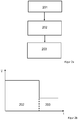
- Figure 2a shows a flow diagram of a method for processing film webs.
- a first step 201 two film webs with motifs arranged next to one another are provided.
- a second step 202 the film webs with the motifs are fed to the injection molding tool, in particular by means of a feed device, in a first phase.
- a third step 203 the film webs are aligned in such a way that each one motif is precisely arranged for each cavity.
- the phases 202, 203 differ in particular by their average film transport speed and / or their film transport distance.
- Figure 2b shows a diagram specifying the average film transport speeds.
- the two films arranged next to one another are transported in the first phase 202 at a higher average film transport speed than in the second phase 203.
- the motifs are in particular aligned in the feed direction and / or in a direction perpendicular to the feed direction in relation to the respective cavities. This ensures that, on the one hand, the motif is quickly introduced into the area of the cavity and, on the other hand, exact positioning is achieved achieved within the cavity, so that the process times can be further reduced.
- the average film transport speed in the first phase 202 is in particular between 1 mm / s and 1000 mm / s, preferably between 250 mm / s and 750 mm / s, more preferably between 450 mm / s and 550 mm / s.
- the average film transport speed in the second phase 203 is in particular between 1 mm / s and 100 mm / s, preferably between 5 mm / s and 50 mm / s.
- the film transport sections in the first phase 202 and second phase 203 may differ from one another. It is advantageous here if the film transport path in the first phase 202 is greater than in the second phase 203.
- the film transport path in the first phase 202 is in particular between 10 mm and 5000 mm, preferably between 1500 mm and 3500 mm, more preferably between 2500 mm and 3000 mm.
- the film transport path in the second phase 203 is in particular between 3 mm and 50 mm, preferably between 3 mm and 10 mm. This film transport path in the second phase 203 is particularly dependent on the size of the register mark.
- the register marks preferably usually have a size of approximately 3 mm ⁇ 3 mm to 20 mm ⁇ 20 mm, in particular of approximately 3 mm ⁇ 3 mm to 10 mm ⁇ 10 mm.
- the width is preferably approximately 3 mm to 20 mm, in particular approximately 3 mm to 10 mm.
- the length and width can also be different in each case, for example a register mark can also have a size of 10 mm ⁇ 8 mm.
- the route covered in the first phase 202 can in particular contain a blind route.
- the blind path is preferably less than the film transport path of the first phase 202.
- the blind path begins with the start of the film transport path of the first phase 202.
- the blind path preferably ends before the end of the film transport path of the first phase 202 Register mark at the end of the first phase 202 allows.
- the second phase 203 begins in particular at a first recognized outer edge of a register mark and ends in particular at a last recognized outer edge of a register mark. This last recognized outer edge of the register mark can preferably be detected particularly precisely because of the low film transport speed.
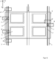
- FIG 3 shows a schematic plan view of a system 10.
- the system 10 has a feed device for film webs 1, 1 '.
- the feed device comprises two film unwinders 2, 2 'and two film rewinders 3, 3'.
- a film unwinder 2, 2 'and a film winder 3, 3' each assigned to a film web 1, 1 '.
- the feed device has a feed direction that is shown in Figure 3 is shown by means of a thick arrow.
- the direction of advance is understood to mean the direction in which the film webs 1, 1 'are guided by the film unwinders 2, 2' in the direction of the film rewinders 3, 3 '.
- the film unwinders 2, 2 'and the film rewinders 3, 3' are arranged in a plane spanned by an x and y coordinate, so that the one between the film unwinders 2, 2 'and the film rewinders 3, 3' Foil webs 1, 1 ′ run in particular along the y-axis, so that the feed direction also runs in the direction of the y-axis.
- a top view is understood here to mean a top view of the two film webs 1, 1 ′ arranged next to one another.
- the system 10 viewed from the direction of the surface normal, that is, a direction perpendicular to a plane spanned by the two film webs 1, 1 ′ arranged next to one another and / or in the closing and opening direction of an injection molding tool 4.
- the direction of the top view is a z direction.
- the injection molding tool 4 shown has the cavities 5.
- the injection molding tool 4 has at least two cavities 5 which are arranged in a direction essentially perpendicular to the feed direction in plan view.
- the direction essentially perpendicular to the feed direction is in Figure 3 shown with a dashed double arrow.
- the injection molding tool 4 can have one or more further cavities 5 in the feed direction.
- This in Figure 3 Injection molding tool 4 shown has two Cavities 5 in the feed direction and two cavities 5 side by side, that is, in a direction perpendicular to the feed direction.
- four plastic molded parts are produced at the same time.
- the cavities 5 are advantageously arranged according to a grid, in particular according to a one- or two-dimensional grid.
- the grid width in this case is preferably between 1 mm and 100 mm, particularly preferably between 10 mm and 40 mm, in the feed direction.
- the grid width perpendicular to the feed direction is preferably between 10 mm and 2000 mm, particularly preferably between 100 mm and 1000 mm.
- the injection molding tool 4 prefferably has a clamping device, in particular a clamping frame, and / or a vacuum suction device.
- a clamping device in particular a clamping frame, and / or a vacuum suction device.
- the motifs 6 can preferably be designed larger than the cavities 5.
- the motifs 6 are preferably designed to be at least 1% larger than the cavities 5. It is thus possible for the motifs 6 to each project beyond a cavity 5 in each direction, preferably between 1 mm and 20 mm.
- the film web 1, 1 ′ and / or the film webs 1, 1 ′ unlike in FIG Figure 3 is shown, have different motifs 6.
- the motifs 6 can be individual images as well as endless motifs.
- Foil webs 1, 1 ' shown have register marks 7, 7'.
- the film webs 1, 1 ' are preferably aligned on the basis of the register marks 7, 7'.
- the register marks 7, 7 ' are preferably designed in such a way that they can be used to determine the positions in the feed direction and / or in a direction perpendicular to the feed direction of the two film webs 1, 1' arranged next to one another.
- a single register mark 7, 7 ' is assigned to each motif 6, so that the position of the assigned motif 6 in the feed direction and in a direction perpendicular to the feed direction can be determined by means of this register mark 7, 7'.
- the distance between the register marks 7, 7 'and the assigned motif 6 is as small as possible, in particular that the distance is between 5 mm and 500 mm, in particular between 15 mm and 200 mm.
- the register marks 7, 7 ' are advantageously each arranged on at least one side edge of the two film webs 1, 1' arranged next to one another in the feed direction. It is also conceivable that the register marks 7, 7 'on both side edges of the two juxtaposed film webs 1,1 'are arranged in the feed direction.
- the two film webs 1, 1 ′ arranged next to one another can also have register marks 7, 7 ′ on both or opposite sides.
- the register mark 7, 7 ' is not set to a fixed geometry. As in Figure 3 shown, they are advantageously rectangular register marks 7, 7 '. Furthermore, however, it is also possible for the register mark 7, 7 'to be designed as a point, cross mark, arrow, polygon or square. It is also possible for the register mark 7, 7 'to be designed as a strip which extends essentially along the film webs 1, 1', in particular in the feed direction.
- the system 10 also has at least one sensor 8 for detecting at least one register mark 7, 7 ′ and / or at least one motif 6.
- the senor 8 it is possible here for the sensor 8 to be a transmitted light and / or incident light sensor.
- the transmitted light sensor is preferably a forked light barrier and the incident light sensor is a reflection sensor.
- the at least one sensor 8 is advantageously at a distance of between 5 mm and 200 mm, preferably between 15 mm and 50 mm, from the cavities 5. In this way, the positioning accuracy of the motifs 6 can be increased further.
- the at least one sensor 8 is arranged in such a way that it essentially detects regions of a film web 1, in particular edge regions of a film web 1, the regions being viewed from above each lie on a side of the one film web 1 facing away from the other film web 1 '.
- control device 9 of the system 10 is preferably designed to control the advance of the two film webs 1, 1 ′ arranged next to one another.
- the control device 9 of the system 10 is expediently designed in such a way that it controls the injection molding tool 4.
- control device 9 it is also possible for the control device 9 to be designed in such a way that the control device 9 controls the injection molding tool 4 according to a precisely fitting arrangement of a motif 6 for each cavity 5, which in particular closes the injection molding tool 4.
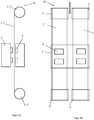
- Figure 4 shows a schematic plan view of a section of a system 10.
- the register mark 7 is used to detect the position of the individual film webs 1, 1 'in the feed direction.
- the register mark 7 ' is used to detect the position of the individual film webs 1, 1' in a direction perpendicular to the feed direction. As in Figure 4 As shown, this means that the register mark 7 is used to detect the position of the individual film webs 1, 1 'in the y-direction and the register mark 7' is used to record the position of the individual film webs 1, 1 'in the x-direction.
- the system 10 includes the sensors 8, 8 '.
- Each sensor 8, 8 ' is preferably assigned to a register mark 7, 7'. This preferably means that the sensor 8 is used to detect the register mark 7 and the sensor 8 'is used to detect the Register mark 7 'is used. As in Figure 4 As can be seen, the sensors 8, 8 'for detecting the register marks 7, 7' can be arranged differently. For the sensors 8, 8 '4 recesses can be present within the injection molding tool.
- FIG. 5a shows a schematic side view of the system 10.
- Figure 5b shows a schematic plan view of the system 10.
- the system 10 has the feed device for film webs 1, 1 '.
- the feed device comprises the two film unwinders 2, 2 'and the two film rewinders 3, 3'.
- a film unwinder 2, 2 'and a film winder 3, 3' each assigned to a film web 1,1 '.
- the injection molding tool 4 shown has the cavities 5.
- the injection molding tool 4 has two cavities 5 which are arranged in a direction essentially perpendicular to the feed direction in a plan view.
- the in Figure 5a or 5b shown injection molding tool 4 two cavities 5 in the feed direction Figure 5a respectively.
- Figure 5b Injection molding tool 4 shown, four plastic molded parts are produced at the same time.
- the tool has two tool halves.
- the film webs 1, 1 ′ with motifs 6 run between the two tool halves.
- Figure 6a shows a schematic representation of the alignment of film webs 1, 1 '.
- Figure 6a shows the generation of release signals, each cavity 5 being assigned a separate release signal 11.
- the release signals 11 are only generated when the corresponding motif 6 is precisely arranged in the respective cavity 5.
- the release signal 11 only occurs in the event of deviations of less than ⁇ 0.1 mm, preferably less than ⁇ 0.05 mm, in the feed direction and / or in a direction perpendicular to the feed direction for each motif 6 aligned with a cavity 5 is produced.
- the deviations preferably include several different tolerances, in particular mechanical tolerances of the feed device, manufacturing tolerances in the manufacture of the film, in particular Pressure tolerances and material properties of the film, in particular its expansion coefficient.
- Figure 7 shows a schematic view of a feed device 20.
- the feed device 20 shown two film webs 1, 1 'with motifs 6, which are arranged next to one another in a direction essentially perpendicular to the feed direction, are transported in the feed direction.
- the feed device 20 comprises two film unwinders 2, 2 'and two film rewinders 3, 3', with one film unwinder 2, 2 'and one film winder 3, 3' each being assigned to a film web 1, 1 '.
- the feed device 20 is preferably designed in such a way that the two film webs 1, 1 ′ arranged next to one another are independent of one another can be provided, fed and / or aligned. As a result, a high degree of accuracy of fit of the motifs 6 to the cavities is achieved for each film web 1, 1 '. It is thus possible to react individually to mutually different motifs 6 of the film webs 1, 1 'and / or to different tolerances of the motifs 6 of the film webs 1, 1'. This further increases the accuracy of fit.
- the in Figure 7 The feed device 20 shown has at least one adjusting device, in particular for aligning the two film webs 1, 1 'arranged next to one another.
- the feed device 20 has two adjusting devices, one adjusting device each being assigned to a film web 1, 1 '.
- the adjusting device preferably comprises at least one stepping motor, in particular for aligning the two film webs 1, 1 'arranged next to one another or for aligning one of the two film webs 1, 1' arranged next to one another.
- the adjustment device comprises a first and a second stepper motor, the first stepper motor for aligning one or both film webs 1, 1 'in the feed direction and the second stepper motor for the alignment of one or both film webs 1, 1' in a direction perpendicular to the feed direction is.
- the stepper motor expediently has a smallest step size of 0.005 mm, preferably 0.001 mm. It also makes sense that the stepper motor has a has a maximum speed of 2000 mm / s. This enables efficient and precise alignment of the two film webs 1, 1 ′ with motifs 6 arranged next to one another.
- the adjustment device can also have a servomotor with a maximum speed of 2000 mm / s.
- a servomotor can position very precisely regardless of a fixed step length, i.e. it can move to defined positions and / or react very precisely to control signals.
- the at least one adjusting device is part of the film unwinder 2, 2 'and / or the film winder 3, 3'.
- the feed device 20 shown further has at least one sensor 8, in particular for detecting register marks 7, 7 ′ and / or motifs 6.
- at least one sensor 8 in particular for detecting register marks 7, 7 ′ and / or motifs 6.
- the feed device 20 has at least one control device 9.
- the control device 9 of the feed device 20 is preferably designed to control the feed of the two film webs 1, 1 'arranged next to one another, in particular to control the independent feed of the two film webs 1, 1' arranged next to one another.
- Figure 8 shows a schematic top view of a motif 6 of a film web 1.
- the motif 6 can for example be a graphically designed outline, a figurative representation, an image, a visually recognizable design element Be a symbol, a logo, a portrait, a pattern, an alphanumeric character, a text, a color design and the like.
- the film web 1 has a subject-free area.
- the subject 6 is surrounded by the subject-free area.
- the motif-free area is formed between the motifs 6 and the side edges of the film webs 1 and / or between the motifs.
- the motif-free area therefore preferably forms a frame, in particular a circumferential frame, around a respective motif 6.
- the width of the motif-free area is preferably between 10 mm and 550 mm, in particular between 25 mm and 300 mm.
- the subject-free area shows, as in Figure 8 shown, preferably a first sub-area 21 and a second sub-area 22, wherein in particular the first sub-area 21 forms space for the positioning of a clamping device, in particular a clamping frame, and / or the second partial area 22 forms space for the positioning of register marks.
- the first sub-area 21 is arranged both directly adjacent to the motif 6 and directly adjacent to the motif 6. This fixes the film webs as close as possible to the motif 6 by means of a clamping device. whereby disruptive factors such as film stretching, wrinkling, etc. are minimized.
- the second sub-area 22 and the motif 6 are, as in FIG Figure 8 shown, spaced from one another.
- the first sub-area 21 is arranged between the motif 6 and the second sub-area 22.
- the register marks preferably arranged in the second sub-area 22 can be detected more easily by sensors or easier positioning of the sensors is possible.
- the first partial area 21 preferably has a width between 5 mm and 500 mm, particularly preferably between 15 mm and 200 mm.
- the second partial area 22 preferably has a width between 5 mm and 50 mm, particularly preferably between 15 mm and 30 mm.
Landscapes
- Engineering & Computer Science (AREA)
- Manufacturing & Machinery (AREA)
- Mechanical Engineering (AREA)
- Injection Moulding Of Plastics Or The Like (AREA)
- Moulds For Moulding Plastics Or The Like (AREA)
- Processing And Handling Of Plastics And Other Materials For Molding In General (AREA)
- Manufacturing Of Printed Circuit Boards (AREA)
- Encapsulation Of And Coatings For Semiconductor Or Solid State Devices (AREA)
Priority Applications (2)
| Application Number | Priority Date | Filing Date | Title |
|---|---|---|---|
| PL17780672T PL3519155T3 (pl) | 2016-09-27 | 2017-09-27 | Sposób przetwarzania folii oraz podajnik |
| HRP20211925TT HRP20211925T1 (hr) | 2016-09-27 | 2017-09-27 | Postupak za obradu folijskih traka i uređaj za punjenje |
Applications Claiming Priority (2)
| Application Number | Priority Date | Filing Date | Title |
|---|---|---|---|
| DE102016118259.1A DE102016118259A1 (de) | 2016-09-27 | 2016-09-27 | Verfahren zum Verarbeiten von Folien sowie eine Vorschubeinrichtung, ein Spritzgusswerkzeug und ein System |
| PCT/EP2017/074453 WO2018060225A1 (de) | 2016-09-27 | 2017-09-27 | Verfahren zum verarbeiten von folien sowie eine vorschubeinrichtung, ein spritzgusswerkzeug und ein system |
Publications (2)
| Publication Number | Publication Date |
|---|---|
| EP3519155A1 EP3519155A1 (de) | 2019-08-07 |
| EP3519155B1 true EP3519155B1 (de) | 2021-10-20 |
Family
ID=60037572
Family Applications (1)
| Application Number | Title | Priority Date | Filing Date |
|---|---|---|---|
| EP17780672.6A Active EP3519155B1 (de) | 2016-09-27 | 2017-09-27 | Verfahren zum verarbeiten von folien sowie eine vorschubeinrichtung |
Country Status (16)
| Country | Link |
|---|---|
| US (1) | US20200016802A1 (pl) |
| EP (1) | EP3519155B1 (pl) |
| JP (1) | JP6977044B2 (pl) |
| KR (1) | KR102384720B1 (pl) |
| CN (1) | CN109952183A (pl) |
| BR (1) | BR112019005555B1 (pl) |
| CA (1) | CA3037620A1 (pl) |
| DE (1) | DE102016118259A1 (pl) |
| ES (1) | ES2899370T3 (pl) |
| HR (1) | HRP20211925T1 (pl) |
| HU (1) | HUE057076T2 (pl) |
| MX (1) | MX2019003389A (pl) |
| PL (1) | PL3519155T3 (pl) |
| PT (1) | PT3519155T (pl) |
| TW (1) | TWI762514B (pl) |
| WO (1) | WO2018060225A1 (pl) |
Families Citing this family (6)
| Publication number | Priority date | Publication date | Assignee | Title |
|---|---|---|---|---|
| JP6803571B2 (ja) * | 2017-04-06 | 2020-12-23 | パナソニックIpマネジメント株式会社 | 加飾成形方法 |
| CN108724680A (zh) * | 2018-05-11 | 2018-11-02 | 宁波诚德兴汽车饰件有限公司 | Imd膜片成型机 |
| DE102018009185A1 (de) | 2018-11-23 | 2019-04-25 | Daimler Ag | Verfahren zum Herstellen eines 3D-geformten Displayglases, Vorrichtung zum Durchführen eines solchen Verfahrens, und Display mit einem solchen 3D-geformten Displayglas |
| DE102018009202B4 (de) | 2018-11-23 | 2026-02-19 | Mercedes-Benz Group AG | Verfahren zum Herstellen eines 3D-geformten Displayglases |
| DE102019004783A1 (de) * | 2019-07-09 | 2021-01-28 | Daimler Ag | Verfahren zum Herstellen einer Tastenfeld-Folienoberfläche sowie Tastenfeld-Folienoberfläche |
| JP2023532167A (ja) * | 2020-04-01 | 2023-07-27 | エーファウ・グループ・エー・タルナー・ゲーエムベーハー | 射出成形する装置および射出成形する方法 |
Family Cites Families (22)
| Publication number | Priority date | Publication date | Assignee | Title |
|---|---|---|---|---|
| US4545752A (en) * | 1982-08-17 | 1985-10-08 | Dai Nippon Insatsu Kabushiki Kaisha | Device for injection molding articles while simultaneously forming patterns thereon |
| US4537739A (en) | 1983-08-22 | 1985-08-27 | Replicap Products, Inc. | Production of molded plastic articles with artwork thereon |
| JPS62128720A (ja) | 1985-11-29 | 1987-06-11 | Dainippon Printing Co Ltd | 射出同時成形法 |
| JPH0675891B2 (ja) * | 1990-09-28 | 1994-09-28 | 日本写真印刷株式会社 | 転写フィルム送り装置 |
| DE4038126C2 (de) | 1990-11-27 | 1993-12-16 | Mannesmann Ag | Verfahren und Vorrichtung zur Herstellung einer dekorierten Chip-Karte |
| JP3514571B2 (ja) | 1995-12-28 | 2004-03-31 | 日本写真印刷株式会社 | 2色成形同時絵付け品の製造方法 |
| JPH106358A (ja) * | 1996-06-24 | 1998-01-13 | Apic Yamada Kk | 樹脂モールド装置におけるリリースフィルムの供給機構 |
| JP2000037753A (ja) * | 1998-07-22 | 2000-02-08 | Nissha Printing Co Ltd | 射出成形用金型とフィルムインサート成形品の製造方法 |
| JP2000210971A (ja) | 1999-01-25 | 2000-08-02 | Sony Corp | インモ―ルド成形装置及びインモ―ルド箔 |
| JP3762270B2 (ja) | 2001-08-30 | 2006-04-05 | 住友重機械工業株式会社 | 成形機及び成形方法 |
| JP3857608B2 (ja) * | 2002-03-29 | 2006-12-13 | 吉田プラ工業株式会社 | 加飾付き樹脂成形品の製造方法 |
| JP2004074476A (ja) * | 2002-08-12 | 2004-03-11 | Mitsubishi Materials Corp | 成形同時転写品の製造方法及び装置 |
| TWI325813B (en) | 2003-03-03 | 2010-06-11 | Ykk Corp | Transferring and molding method and transferring and molding apparatus |
| DE602005027320D1 (de) * | 2004-02-18 | 2011-05-19 | Nissha Printing | Doppelseitiges werkzeug zum dekorieren im werkzeug und verfahren zur herstellung eines im werkzeug doppelseitig dekorierten produkts |
| JP2006272883A (ja) * | 2005-03-30 | 2006-10-12 | Nissha Printing Co Ltd | 転写成形装置及び転写成形方法 |
| JP4789645B2 (ja) * | 2006-02-20 | 2011-10-12 | 吉田プラ工業株式会社 | 樹脂成形品の製造方法及び製造装置 |
| US20070194489A1 (en) | 2006-02-20 | 2007-08-23 | Yoshida Industry Co., Ltd. | Method of manufacturing resin molded product |
| US7922952B2 (en) | 2007-10-04 | 2011-04-12 | Nissha Printing Co., Ltd. | Simultaneous injection-molding and decorating method |
| JP4703783B2 (ja) * | 2008-08-27 | 2011-06-15 | 日本写真印刷株式会社 | 加飾シート及び成形同時加飾装置 |
| JP5522946B2 (ja) * | 2009-01-15 | 2014-06-18 | サンプラスチックス株式会社 | インモールドラベル容器の製造方法及びその製造装置 |
| KR20100086563A (ko) * | 2009-01-23 | 2010-08-02 | 주식회사 동신이엔텍 | 전사 성형 장치 |
| JP6520133B2 (ja) * | 2015-01-16 | 2019-05-29 | 大日本印刷株式会社 | 積層体ならびにそれを用いた導電性基材の製造方法および電子デバイスの製造方法 |
-
2016
- 2016-09-27 DE DE102016118259.1A patent/DE102016118259A1/de not_active Ceased
-
2017
- 2017-09-27 CA CA3037620A patent/CA3037620A1/en active Pending
- 2017-09-27 KR KR1020197012149A patent/KR102384720B1/ko active Active
- 2017-09-27 HU HUE17780672A patent/HUE057076T2/hu unknown
- 2017-09-27 TW TW106133202A patent/TWI762514B/zh active
- 2017-09-27 WO PCT/EP2017/074453 patent/WO2018060225A1/de not_active Ceased
- 2017-09-27 US US16/335,531 patent/US20200016802A1/en not_active Abandoned
- 2017-09-27 PL PL17780672T patent/PL3519155T3/pl unknown
- 2017-09-27 PT PT177806726T patent/PT3519155T/pt unknown
- 2017-09-27 BR BR112019005555-0A patent/BR112019005555B1/pt active IP Right Grant
- 2017-09-27 JP JP2019537884A patent/JP6977044B2/ja active Active
- 2017-09-27 EP EP17780672.6A patent/EP3519155B1/de active Active
- 2017-09-27 ES ES17780672T patent/ES2899370T3/es active Active
- 2017-09-27 HR HRP20211925TT patent/HRP20211925T1/hr unknown
- 2017-09-27 MX MX2019003389A patent/MX2019003389A/es unknown
- 2017-09-27 CN CN201780070186.XA patent/CN109952183A/zh active Pending
Non-Patent Citations (1)
| Title |
|---|
| None * |
Also Published As
| Publication number | Publication date |
|---|---|
| BR112019005555A2 (pt) | 2019-06-04 |
| CN109952183A (zh) | 2019-06-28 |
| PL3519155T3 (pl) | 2022-02-07 |
| BR112019005555B1 (pt) | 2023-04-18 |
| HUE057076T2 (hu) | 2022-04-28 |
| DE102016118259A1 (de) | 2018-03-29 |
| ES2899370T3 (es) | 2022-03-11 |
| CA3037620A1 (en) | 2018-04-05 |
| US20200016802A1 (en) | 2020-01-16 |
| TWI762514B (zh) | 2022-05-01 |
| TW201817579A (zh) | 2018-05-16 |
| PT3519155T (pt) | 2021-11-23 |
| WO2018060225A1 (de) | 2018-04-05 |
| EP3519155A1 (de) | 2019-08-07 |
| JP6977044B2 (ja) | 2021-12-08 |
| HRP20211925T1 (hr) | 2022-03-18 |
| KR102384720B1 (ko) | 2022-04-08 |
| JP2019529195A (ja) | 2019-10-17 |
| MX2019003389A (es) | 2019-06-06 |
| KR20190062478A (ko) | 2019-06-05 |
Similar Documents
| Publication | Publication Date | Title |
|---|---|---|
| EP3519155B1 (de) | Verfahren zum verarbeiten von folien sowie eine vorschubeinrichtung | |
| EP3439850B1 (de) | Verfahren und formwerkzeug zur warmumformung eines ebenen thermoplastischen schichtstoffes | |
| EP2448740B1 (de) | Mehrschichtkörper | |
| EP3331699B1 (de) | Verfahren und vorrichtung zum herstellen einer mehrschichtfolie | |
| EP2393660B1 (de) | Verfahren zur herstellung von mehrlagigen sicherheitsprodukten | |
| EP3083183B1 (de) | Kunststoffformteil und verfahren zu dessen herstellung | |
| EP1851069B1 (de) | Mehrschichtfolie, damit dekorierter spritzgussartikel und verfahren zur herstellung des dekorierten spritzgussartikels | |
| EP2865511B2 (de) | Düse und Verfahren zur Platten- oder Folienextrusion | |
| DE102018128194A1 (de) | Verfahren zur Herstellung eines Bauteils sowie Spritzgießvorrichtung | |
| EP4733034A2 (de) | Verfahren zur herstellung eines bauteils und vorrichtung zur herstellung eines bauteils | |
| EP3481632A1 (de) | Transferfolie, verfahren zur herstellung einer transferfolie sowie verwendung einer transferfolie und verfahren zur beschichtung eines bauteils | |
| EP3433101B1 (de) | Verfahren zur herstellung eines folienverbundes aus mehreren materialbahnen für ein wert- oder sicherheitsdokument | |
| EP2160276B1 (de) | Verfahren zum herstellen von farbigen, dreidimensional strukturierten bauteilen mit freiformflächen | |
| EP4110578A1 (de) | Verfahren und vorrichtung zum dekorieren eines spritzgussformteils sowie ein spritzgussformteil | |
| DE102025104195B4 (de) | Verfahren zur Herstellung eines Mehrschichtkörpers, Mehrschichtkörper, Außenschichtverbund und Verwendung eines Außenschichtverbunds zur Herstellung eines Mehrschichtkörpers | |
| EP3500435B1 (de) | Anlage und verfahren zum produzieren von individuellen wert- und sicherheitsdokumenten aus vormaterialstücken | |
| WO2023166006A1 (de) | Verfahren zur herstellung eines artikels, ein artikel und verwendung des artikels | |
| EP4681935A1 (de) | Folienmaterial für sicherheitselemente in form von folienpatches |
Legal Events
| Date | Code | Title | Description |
|---|---|---|---|
| REG | Reference to a national code |
Ref country code: HR Ref legal event code: TUEP Ref document number: P20211925T Country of ref document: HR |
|
| STAA | Information on the status of an ep patent application or granted ep patent |
Free format text: STATUS: UNKNOWN |
|
| STAA | Information on the status of an ep patent application or granted ep patent |
Free format text: STATUS: THE INTERNATIONAL PUBLICATION HAS BEEN MADE |
|
| PUAI | Public reference made under article 153(3) epc to a published international application that has entered the european phase |
Free format text: ORIGINAL CODE: 0009012 |
|
| STAA | Information on the status of an ep patent application or granted ep patent |
Free format text: STATUS: REQUEST FOR EXAMINATION WAS MADE |
|
| 17P | Request for examination filed |
Effective date: 20190411 |
|
| AK | Designated contracting states |
Kind code of ref document: A1 Designated state(s): AL AT BE BG CH CY CZ DE DK EE ES FI FR GB GR HR HU IE IS IT LI LT LU LV MC MK MT NL NO PL PT RO RS SE SI SK SM TR |
|
| AX | Request for extension of the european patent |
Extension state: BA ME |
|
| STAA | Information on the status of an ep patent application or granted ep patent |
Free format text: STATUS: EXAMINATION IS IN PROGRESS |
|
| 17Q | First examination report despatched |
Effective date: 20191024 |
|
| DAV | Request for validation of the european patent (deleted) | ||
| DAX | Request for extension of the european patent (deleted) | ||
| GRAP | Despatch of communication of intention to grant a patent |
Free format text: ORIGINAL CODE: EPIDOSNIGR1 |
|
| STAA | Information on the status of an ep patent application or granted ep patent |
Free format text: STATUS: GRANT OF PATENT IS INTENDED |
|
| GRAS | Grant fee paid |
Free format text: ORIGINAL CODE: EPIDOSNIGR3 |
|
| INTG | Intention to grant announced |
Effective date: 20210818 |
|
| GRAA | (expected) grant |
Free format text: ORIGINAL CODE: 0009210 |
|
| STAA | Information on the status of an ep patent application or granted ep patent |
Free format text: STATUS: THE PATENT HAS BEEN GRANTED |
|
| AK | Designated contracting states |
Kind code of ref document: B1 Designated state(s): AL AT BE BG CH CY CZ DE DK EE ES FI FR GB GR HR HU IE IS IT LI LT LU LV MC MK MT NL NO PL PT RO RS SE SI SK SM TR |
|
| REG | Reference to a national code |
Ref country code: GB Ref legal event code: FG4D Free format text: NOT ENGLISH |
|
| REG | Reference to a national code |
Ref country code: CH Ref legal event code: EP |
|
| REG | Reference to a national code |
Ref country code: IE Ref legal event code: FG4D Free format text: LANGUAGE OF EP DOCUMENT: GERMAN |
|
| REG | Reference to a national code |
Ref country code: DE Ref legal event code: R096 Ref document number: 502017011787 Country of ref document: DE |
|
| REG | Reference to a national code |
Ref country code: AT Ref legal event code: REF Ref document number: 1439569 Country of ref document: AT Kind code of ref document: T Effective date: 20211115 |
|
| REG | Reference to a national code |
Ref country code: PT Ref legal event code: SC4A Ref document number: 3519155 Country of ref document: PT Date of ref document: 20211123 Kind code of ref document: T Free format text: AVAILABILITY OF NATIONAL TRANSLATION Effective date: 20211116 |
|
| REG | Reference to a national code |
Ref country code: NL Ref legal event code: FP |
|
| REG | Reference to a national code |
Ref country code: LT Ref legal event code: MG9D |
|
| REG | Reference to a national code |
Ref country code: SK Ref legal event code: T3 Ref document number: E 38943 Country of ref document: SK |
|
| REG | Reference to a national code |
Ref country code: ES Ref legal event code: FG2A Ref document number: 2899370 Country of ref document: ES Kind code of ref document: T3 Effective date: 20220311 |
|
| REG | Reference to a national code |
Ref country code: HR Ref legal event code: T1PR Ref document number: P20211925 Country of ref document: HR |
|
| REG | Reference to a national code |
Ref country code: HU Ref legal event code: AG4A Ref document number: E057076 Country of ref document: HU |
|
| PG25 | Lapsed in a contracting state [announced via postgrant information from national office to epo] |
Ref country code: RS Free format text: LAPSE BECAUSE OF FAILURE TO SUBMIT A TRANSLATION OF THE DESCRIPTION OR TO PAY THE FEE WITHIN THE PRESCRIBED TIME-LIMIT Effective date: 20211020 Ref country code: LT Free format text: LAPSE BECAUSE OF FAILURE TO SUBMIT A TRANSLATION OF THE DESCRIPTION OR TO PAY THE FEE WITHIN THE PRESCRIBED TIME-LIMIT Effective date: 20211020 Ref country code: FI Free format text: LAPSE BECAUSE OF FAILURE TO SUBMIT A TRANSLATION OF THE DESCRIPTION OR TO PAY THE FEE WITHIN THE PRESCRIBED TIME-LIMIT Effective date: 20211020 Ref country code: BG Free format text: LAPSE BECAUSE OF FAILURE TO SUBMIT A TRANSLATION OF THE DESCRIPTION OR TO PAY THE FEE WITHIN THE PRESCRIBED TIME-LIMIT Effective date: 20220120 |
|
| PG25 | Lapsed in a contracting state [announced via postgrant information from national office to epo] |
Ref country code: IS Free format text: LAPSE BECAUSE OF FAILURE TO SUBMIT A TRANSLATION OF THE DESCRIPTION OR TO PAY THE FEE WITHIN THE PRESCRIBED TIME-LIMIT Effective date: 20220220 Ref country code: SE Free format text: LAPSE BECAUSE OF FAILURE TO SUBMIT A TRANSLATION OF THE DESCRIPTION OR TO PAY THE FEE WITHIN THE PRESCRIBED TIME-LIMIT Effective date: 20211020 Ref country code: NO Free format text: LAPSE BECAUSE OF FAILURE TO SUBMIT A TRANSLATION OF THE DESCRIPTION OR TO PAY THE FEE WITHIN THE PRESCRIBED TIME-LIMIT Effective date: 20220120 Ref country code: LV Free format text: LAPSE BECAUSE OF FAILURE TO SUBMIT A TRANSLATION OF THE DESCRIPTION OR TO PAY THE FEE WITHIN THE PRESCRIBED TIME-LIMIT Effective date: 20211020 Ref country code: GR Free format text: LAPSE BECAUSE OF FAILURE TO SUBMIT A TRANSLATION OF THE DESCRIPTION OR TO PAY THE FEE WITHIN THE PRESCRIBED TIME-LIMIT Effective date: 20220121 |
|
| REG | Reference to a national code |
Ref country code: DE Ref legal event code: R097 Ref document number: 502017011787 Country of ref document: DE |
|
| PG25 | Lapsed in a contracting state [announced via postgrant information from national office to epo] |
Ref country code: SM Free format text: LAPSE BECAUSE OF FAILURE TO SUBMIT A TRANSLATION OF THE DESCRIPTION OR TO PAY THE FEE WITHIN THE PRESCRIBED TIME-LIMIT Effective date: 20211020 Ref country code: EE Free format text: LAPSE BECAUSE OF FAILURE TO SUBMIT A TRANSLATION OF THE DESCRIPTION OR TO PAY THE FEE WITHIN THE PRESCRIBED TIME-LIMIT Effective date: 20211020 Ref country code: DK Free format text: LAPSE BECAUSE OF FAILURE TO SUBMIT A TRANSLATION OF THE DESCRIPTION OR TO PAY THE FEE WITHIN THE PRESCRIBED TIME-LIMIT Effective date: 20211020 |
|
| PLBE | No opposition filed within time limit |
Free format text: ORIGINAL CODE: 0009261 |
|
| STAA | Information on the status of an ep patent application or granted ep patent |
Free format text: STATUS: NO OPPOSITION FILED WITHIN TIME LIMIT |
|
| 26N | No opposition filed |
Effective date: 20220721 |
|
| REG | Reference to a national code |
Ref country code: HR Ref legal event code: ODRP Ref document number: P20211925 Country of ref document: HR Payment date: 20220916 Year of fee payment: 6 |
|
| PG25 | Lapsed in a contracting state [announced via postgrant information from national office to epo] |
Ref country code: AL Free format text: LAPSE BECAUSE OF FAILURE TO SUBMIT A TRANSLATION OF THE DESCRIPTION OR TO PAY THE FEE WITHIN THE PRESCRIBED TIME-LIMIT Effective date: 20211020 |
|
| PG25 | Lapsed in a contracting state [announced via postgrant information from national office to epo] |
Ref country code: SI Free format text: LAPSE BECAUSE OF FAILURE TO SUBMIT A TRANSLATION OF THE DESCRIPTION OR TO PAY THE FEE WITHIN THE PRESCRIBED TIME-LIMIT Effective date: 20211020 |
|
| PG25 | Lapsed in a contracting state [announced via postgrant information from national office to epo] |
Ref country code: MC Free format text: LAPSE BECAUSE OF FAILURE TO SUBMIT A TRANSLATION OF THE DESCRIPTION OR TO PAY THE FEE WITHIN THE PRESCRIBED TIME-LIMIT Effective date: 20211020 |
|
| REG | Reference to a national code |
Ref country code: CH Ref legal event code: PL |
|
| PG25 | Lapsed in a contracting state [announced via postgrant information from national office to epo] |
Ref country code: LU Free format text: LAPSE BECAUSE OF NON-PAYMENT OF DUE FEES Effective date: 20220927 |
|
| PG25 | Lapsed in a contracting state [announced via postgrant information from national office to epo] |
Ref country code: LI Free format text: LAPSE BECAUSE OF NON-PAYMENT OF DUE FEES Effective date: 20220930 Ref country code: IE Free format text: LAPSE BECAUSE OF NON-PAYMENT OF DUE FEES Effective date: 20220927 Ref country code: CH Free format text: LAPSE BECAUSE OF NON-PAYMENT OF DUE FEES Effective date: 20220930 |
|
| REG | Reference to a national code |
Ref country code: HR Ref legal event code: ODRP Ref document number: P20211925 Country of ref document: HR Payment date: 20230915 Year of fee payment: 7 |
|
| PG25 | Lapsed in a contracting state [announced via postgrant information from national office to epo] |
Ref country code: CY Free format text: LAPSE BECAUSE OF FAILURE TO SUBMIT A TRANSLATION OF THE DESCRIPTION OR TO PAY THE FEE WITHIN THE PRESCRIBED TIME-LIMIT Effective date: 20211020 |
|
| PG25 | Lapsed in a contracting state [announced via postgrant information from national office to epo] |
Ref country code: MK Free format text: LAPSE BECAUSE OF FAILURE TO SUBMIT A TRANSLATION OF THE DESCRIPTION OR TO PAY THE FEE WITHIN THE PRESCRIBED TIME-LIMIT Effective date: 20211020 |
|
| PG25 | Lapsed in a contracting state [announced via postgrant information from national office to epo] |
Ref country code: MT Free format text: LAPSE BECAUSE OF FAILURE TO SUBMIT A TRANSLATION OF THE DESCRIPTION OR TO PAY THE FEE WITHIN THE PRESCRIBED TIME-LIMIT Effective date: 20211020 |
|
| REG | Reference to a national code |
Ref country code: HR Ref legal event code: ODRP Ref document number: P20211925 Country of ref document: HR Payment date: 20240920 Year of fee payment: 8 |
|
| PGFP | Annual fee paid to national office [announced via postgrant information from national office to epo] |
Ref country code: PT Payment date: 20250912 Year of fee payment: 9 |
|
| REG | Reference to a national code |
Ref country code: HR Ref legal event code: ODRP Ref document number: P20211925 Country of ref document: HR Payment date: 20250916 Year of fee payment: 9 |
|
| PGFP | Annual fee paid to national office [announced via postgrant information from national office to epo] |
Ref country code: PL Payment date: 20250730 Year of fee payment: 9 Ref country code: TR Payment date: 20250918 Year of fee payment: 9 Ref country code: NL Payment date: 20250922 Year of fee payment: 9 |
|
| PGFP | Annual fee paid to national office [announced via postgrant information from national office to epo] |
Ref country code: HU Payment date: 20250917 Year of fee payment: 9 Ref country code: BE Payment date: 20250919 Year of fee payment: 9 Ref country code: GB Payment date: 20250923 Year of fee payment: 9 |
|
| PGFP | Annual fee paid to national office [announced via postgrant information from national office to epo] |
Ref country code: HR Payment date: 20250916 Year of fee payment: 9 |
|
| PGFP | Annual fee paid to national office [announced via postgrant information from national office to epo] |
Ref country code: FR Payment date: 20250924 Year of fee payment: 9 Ref country code: AT Payment date: 20250918 Year of fee payment: 9 |
|
| PGFP | Annual fee paid to national office [announced via postgrant information from national office to epo] |
Ref country code: CZ Payment date: 20250912 Year of fee payment: 9 |
|
| PGFP | Annual fee paid to national office [announced via postgrant information from national office to epo] |
Ref country code: RO Payment date: 20250918 Year of fee payment: 9 |
|
| PGFP | Annual fee paid to national office [announced via postgrant information from national office to epo] |
Ref country code: SK Payment date: 20250918 Year of fee payment: 9 |
|
| PGFP | Annual fee paid to national office [announced via postgrant information from national office to epo] |
Ref country code: DE Payment date: 20250929 Year of fee payment: 9 |
|
| PGFP | Annual fee paid to national office [announced via postgrant information from national office to epo] |
Ref country code: IT Payment date: 20250930 Year of fee payment: 9 |
|
| PGFP | Annual fee paid to national office [announced via postgrant information from national office to epo] |
Ref country code: ES Payment date: 20251020 Year of fee payment: 9 |