EP3553429B1 - Kühlschrank - Google Patents
Kühlschrank Download PDFInfo
- Publication number
- EP3553429B1 EP3553429B1 EP19171947.5A EP19171947A EP3553429B1 EP 3553429 B1 EP3553429 B1 EP 3553429B1 EP 19171947 A EP19171947 A EP 19171947A EP 3553429 B1 EP3553429 B1 EP 3553429B1
- Authority
- EP
- European Patent Office
- Prior art keywords
- inner case
- coupling
- grille
- refrigerator
- duct
- Prior art date
- Legal status (The legal status is an assumption and is not a legal conclusion. Google has not performed a legal analysis and makes no representation as to the accuracy of the status listed.)
- Active
Links
Images










Classifications
-
- F—MECHANICAL ENGINEERING; LIGHTING; HEATING; WEAPONS; BLASTING
- F25—REFRIGERATION OR COOLING; COMBINED HEATING AND REFRIGERATION SYSTEMS; HEAT PUMP SYSTEMS; MANUFACTURE OR STORAGE OF ICE; LIQUEFACTION SOLIDIFICATION OF GASES
- F25D—REFRIGERATORS; COLD ROOMS; ICE-BOXES; COOLING OR FREEZING APPARATUS NOT OTHERWISE PROVIDED FOR
- F25D17/00—Arrangements for circulating cooling fluids; Arrangements for circulating gas, e.g. air, within refrigerated spaces
- F25D17/04—Arrangements for circulating cooling fluids; Arrangements for circulating gas, e.g. air, within refrigerated spaces for circulating air, e.g. by convection
- F25D17/06—Arrangements for circulating cooling fluids; Arrangements for circulating gas, e.g. air, within refrigerated spaces for circulating air, e.g. by convection by forced circulation
- F25D17/062—Arrangements for circulating cooling fluids; Arrangements for circulating gas, e.g. air, within refrigerated spaces for circulating air, e.g. by convection by forced circulation in household refrigerators
- F25D17/065—Arrangements for circulating cooling fluids; Arrangements for circulating gas, e.g. air, within refrigerated spaces for circulating air, e.g. by convection by forced circulation in household refrigerators with compartments at different temperatures
-
- F—MECHANICAL ENGINEERING; LIGHTING; HEATING; WEAPONS; BLASTING
- F25—REFRIGERATION OR COOLING; COMBINED HEATING AND REFRIGERATION SYSTEMS; HEAT PUMP SYSTEMS; MANUFACTURE OR STORAGE OF ICE; LIQUEFACTION SOLIDIFICATION OF GASES
- F25D—REFRIGERATORS; COLD ROOMS; ICE-BOXES; COOLING OR FREEZING APPARATUS NOT OTHERWISE PROVIDED FOR
- F25D17/00—Arrangements for circulating cooling fluids; Arrangements for circulating gas, e.g. air, within refrigerated spaces
- F25D17/04—Arrangements for circulating cooling fluids; Arrangements for circulating gas, e.g. air, within refrigerated spaces for circulating air, e.g. by convection
- F25D17/06—Arrangements for circulating cooling fluids; Arrangements for circulating gas, e.g. air, within refrigerated spaces for circulating air, e.g. by convection by forced circulation
- F25D17/062—Arrangements for circulating cooling fluids; Arrangements for circulating gas, e.g. air, within refrigerated spaces for circulating air, e.g. by convection by forced circulation in household refrigerators
-
- F—MECHANICAL ENGINEERING; LIGHTING; HEATING; WEAPONS; BLASTING
- F25—REFRIGERATION OR COOLING; COMBINED HEATING AND REFRIGERATION SYSTEMS; HEAT PUMP SYSTEMS; MANUFACTURE OR STORAGE OF ICE; LIQUEFACTION SOLIDIFICATION OF GASES
- F25D—REFRIGERATORS; COLD ROOMS; ICE-BOXES; COOLING OR FREEZING APPARATUS NOT OTHERWISE PROVIDED FOR
- F25D11/00—Self-contained movable devices, e.g. domestic refrigerators
- F25D11/02—Self-contained movable devices, e.g. domestic refrigerators with cooling compartments at different temperatures
-
- F—MECHANICAL ENGINEERING; LIGHTING; HEATING; WEAPONS; BLASTING
- F25—REFRIGERATION OR COOLING; COMBINED HEATING AND REFRIGERATION SYSTEMS; HEAT PUMP SYSTEMS; MANUFACTURE OR STORAGE OF ICE; LIQUEFACTION SOLIDIFICATION OF GASES
- F25B—REFRIGERATION MACHINES, PLANTS OR SYSTEMS; COMBINED HEATING AND REFRIGERATION SYSTEMS; HEAT PUMP SYSTEMS
- F25B39/00—Evaporators; Condensers
-
- F—MECHANICAL ENGINEERING; LIGHTING; HEATING; WEAPONS; BLASTING
- F25—REFRIGERATION OR COOLING; COMBINED HEATING AND REFRIGERATION SYSTEMS; HEAT PUMP SYSTEMS; MANUFACTURE OR STORAGE OF ICE; LIQUEFACTION SOLIDIFICATION OF GASES
- F25D—REFRIGERATORS; COLD ROOMS; ICE-BOXES; COOLING OR FREEZING APPARATUS NOT OTHERWISE PROVIDED FOR
- F25D19/00—Arrangement or mounting of refrigeration units with respect to devices or objects to be refrigerated, e.g. infrared detectors
- F25D19/003—Arrangement or mounting of refrigeration units with respect to devices or objects to be refrigerated, e.g. infrared detectors with respect to movable containers
-
- F—MECHANICAL ENGINEERING; LIGHTING; HEATING; WEAPONS; BLASTING
- F25—REFRIGERATION OR COOLING; COMBINED HEATING AND REFRIGERATION SYSTEMS; HEAT PUMP SYSTEMS; MANUFACTURE OR STORAGE OF ICE; LIQUEFACTION SOLIDIFICATION OF GASES
- F25D—REFRIGERATORS; COLD ROOMS; ICE-BOXES; COOLING OR FREEZING APPARATUS NOT OTHERWISE PROVIDED FOR
- F25D23/00—General constructional features
- F25D23/06—Walls
- F25D23/062—Walls defining a cabinet
- F25D23/063—Walls defining a cabinet formed by an assembly of panels
-
- F—MECHANICAL ENGINEERING; LIGHTING; HEATING; WEAPONS; BLASTING
- F25—REFRIGERATION OR COOLING; COMBINED HEATING AND REFRIGERATION SYSTEMS; HEAT PUMP SYSTEMS; MANUFACTURE OR STORAGE OF ICE; LIQUEFACTION SOLIDIFICATION OF GASES
- F25D—REFRIGERATORS; COLD ROOMS; ICE-BOXES; COOLING OR FREEZING APPARATUS NOT OTHERWISE PROVIDED FOR
- F25D23/00—General constructional features
- F25D23/06—Walls
- F25D23/062—Walls defining a cabinet
- F25D23/064—Walls defining a cabinet formed by moulding, e.g. moulding in situ
-
- F—MECHANICAL ENGINEERING; LIGHTING; HEATING; WEAPONS; BLASTING
- F25—REFRIGERATION OR COOLING; COMBINED HEATING AND REFRIGERATION SYSTEMS; HEAT PUMP SYSTEMS; MANUFACTURE OR STORAGE OF ICE; LIQUEFACTION SOLIDIFICATION OF GASES
- F25D—REFRIGERATORS; COLD ROOMS; ICE-BOXES; COOLING OR FREEZING APPARATUS NOT OTHERWISE PROVIDED FOR
- F25D23/00—General constructional features
- F25D23/06—Walls
- F25D23/065—Details
- F25D23/068—Arrangements for circulating fluids through the insulating material
-
- F—MECHANICAL ENGINEERING; LIGHTING; HEATING; WEAPONS; BLASTING
- F25—REFRIGERATION OR COOLING; COMBINED HEATING AND REFRIGERATION SYSTEMS; HEAT PUMP SYSTEMS; MANUFACTURE OR STORAGE OF ICE; LIQUEFACTION SOLIDIFICATION OF GASES
- F25D—REFRIGERATORS; COLD ROOMS; ICE-BOXES; COOLING OR FREEZING APPARATUS NOT OTHERWISE PROVIDED FOR
- F25D23/00—General constructional features
- F25D23/12—Arrangements of compartments additional to cooling compartments; Combinations of refrigerators with other equipment, e.g. stove
-
- F—MECHANICAL ENGINEERING; LIGHTING; HEATING; WEAPONS; BLASTING
- F25—REFRIGERATION OR COOLING; COMBINED HEATING AND REFRIGERATION SYSTEMS; HEAT PUMP SYSTEMS; MANUFACTURE OR STORAGE OF ICE; LIQUEFACTION SOLIDIFICATION OF GASES
- F25B—REFRIGERATION MACHINES, PLANTS OR SYSTEMS; COMBINED HEATING AND REFRIGERATION SYSTEMS; HEAT PUMP SYSTEMS
- F25B39/00—Evaporators; Condensers
- F25B39/02—Evaporators
-
- F—MECHANICAL ENGINEERING; LIGHTING; HEATING; WEAPONS; BLASTING
- F25—REFRIGERATION OR COOLING; COMBINED HEATING AND REFRIGERATION SYSTEMS; HEAT PUMP SYSTEMS; MANUFACTURE OR STORAGE OF ICE; LIQUEFACTION SOLIDIFICATION OF GASES
- F25D—REFRIGERATORS; COLD ROOMS; ICE-BOXES; COOLING OR FREEZING APPARATUS NOT OTHERWISE PROVIDED FOR
- F25D2201/00—Insulation
- F25D2201/10—Insulation with respect to heat
- F25D2201/12—Insulation with respect to heat using an insulating packing material
- F25D2201/126—Insulation with respect to heat using an insulating packing material of cellular type
-
- F—MECHANICAL ENGINEERING; LIGHTING; HEATING; WEAPONS; BLASTING
- F25—REFRIGERATION OR COOLING; COMBINED HEATING AND REFRIGERATION SYSTEMS; HEAT PUMP SYSTEMS; MANUFACTURE OR STORAGE OF ICE; LIQUEFACTION SOLIDIFICATION OF GASES
- F25D—REFRIGERATORS; COLD ROOMS; ICE-BOXES; COOLING OR FREEZING APPARATUS NOT OTHERWISE PROVIDED FOR
- F25D23/00—General constructional features
- F25D23/06—Walls
- F25D23/065—Details
- F25D23/066—Liners
-
- F—MECHANICAL ENGINEERING; LIGHTING; HEATING; WEAPONS; BLASTING
- F25—REFRIGERATION OR COOLING; COMBINED HEATING AND REFRIGERATION SYSTEMS; HEAT PUMP SYSTEMS; MANUFACTURE OR STORAGE OF ICE; LIQUEFACTION SOLIDIFICATION OF GASES
- F25D—REFRIGERATORS; COLD ROOMS; ICE-BOXES; COOLING OR FREEZING APPARATUS NOT OTHERWISE PROVIDED FOR
- F25D2317/00—Details or arrangements for circulating cooling fluids; Details or arrangements for circulating gas, e.g. air, within refrigerated spaces, not provided for in other groups of this subclass
- F25D2317/06—Details or arrangements for circulating cooling fluids; Details or arrangements for circulating gas, e.g. air, within refrigerated spaces, not provided for in other groups of this subclass with forced air circulation
- F25D2317/063—Details or arrangements for circulating cooling fluids; Details or arrangements for circulating gas, e.g. air, within refrigerated spaces, not provided for in other groups of this subclass with forced air circulation with air guides
-
- F—MECHANICAL ENGINEERING; LIGHTING; HEATING; WEAPONS; BLASTING
- F25—REFRIGERATION OR COOLING; COMBINED HEATING AND REFRIGERATION SYSTEMS; HEAT PUMP SYSTEMS; MANUFACTURE OR STORAGE OF ICE; LIQUEFACTION SOLIDIFICATION OF GASES
- F25D—REFRIGERATORS; COLD ROOMS; ICE-BOXES; COOLING OR FREEZING APPARATUS NOT OTHERWISE PROVIDED FOR
- F25D2317/00—Details or arrangements for circulating cooling fluids; Details or arrangements for circulating gas, e.g. air, within refrigerated spaces, not provided for in other groups of this subclass
- F25D2317/06—Details or arrangements for circulating cooling fluids; Details or arrangements for circulating gas, e.g. air, within refrigerated spaces, not provided for in other groups of this subclass with forced air circulation
- F25D2317/067—Details or arrangements for circulating cooling fluids; Details or arrangements for circulating gas, e.g. air, within refrigerated spaces, not provided for in other groups of this subclass with forced air circulation characterised by air ducts
Definitions
- This application relates to a refrigerator.
- a refrigerator is divided into a refrigerator compartment and a freezer compartment.
- a door is installed at a front surface of the refrigerator.
- an inside of the refrigerator, in particular, an accommodation space like the refrigerator compartment is characterized in that the cooling air should be circulated therein for a long time.
- Document JP 2007 064536 discloses a refrigerator with a metal plate attached to an inner surface of the inner case.
- Documents US 2 432 042 A , US 2 957 320 A and US 2 285 947 A also disclose relevant prior art.
- the present invention is directed to providing a refrigerator according to claim 1 which is able to increase a circulating force of cooling air therein.
- Other aspects of the invention are disclosed in the dependent claims.
- first, second, A, B, (a), (b) or the like may be used herein.
- Each of these terminologies is not used to define an essence, order or sequence of a corresponding component but used merely to distinguish the corresponding component from other component(s). It should be noted that if it is described in the specification that one component is “connected,” “coupled” or “joined” to another component, the former may be directly “connected,” “coupled,” and “joined” to the latter or “connected”, “coupled”, and “joined” to the latter via another component.
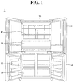
- FIG. 1 illustrates an example refrigerator.
- a refrigerator may include a main body 10 in which a storage compartment is formed, and a refrigerator compartment door 11 and a freezer compartment door 12 which are rotatably installed at both sides of the main body 10 to selectively open and close the storage compartment.
- the storage compartment includes a freezer compartment for keeping a stored product frozen, and a refrigerator compartment for keeping the stored product refrigerated.
- the freezer compartment and the refrigerator compartment may be independently shielded by the freezer compartment door 12 and the refrigerator compartment door 11, respectively.
- one or more storage boxes 14 which are provided to be withdrawn to a front of the storage compartment may be formed at the main body 10, and the stored product such as vegetables and fruits may be stored in the storage boxes 14.
- one or more shelves 13 which divide the storage compartment into a plurality of areas may be formed at the main body 10.
- the stored product may be stored in the storage compartment while being seated on the shelves 13.
- a door basket 15 which accommodates the stored product may be provided at the freezer compartment door 12.
- the refrigerator illustrated in the drawing is an example implementation.
- the door basket 15 may be provided at both sides of the refrigerator compartment door 11, and the storage boxes 14 and the shelves 13 may be provided at both of the freezer compartment and the refrigerator compartment.
- the main body 10 of the refrigerator will be described in detail.
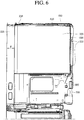
- FIGS. 2 , 6 , and 7 illustrate example main bodies of a refrigerator.
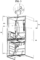
- FIG. 3 illustrates an example rear duct that is removed from a main body of a refrigerator.
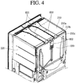
- FIG. 4 illustrates an example outer case that is removed from a refrigerator body.
- FIG. 5 illustrates an example upper duct that is removed from a refrigerator body.
- FIG. 8 illustrates an example metal plate, an example upper duct, and an example grille part of a main body of a refrigerator.
- the refrigerator may include an outer case 100 which forms an exterior of the main body 10, an inner case 200 which is formed inside the outer case 100, and a metal plate 300 which is attached to an inner surface of the inner case.
- the refrigerator may further include an evaporator 700 which is disposed between a rear surface of the inner case 200 and a rear surface of the outer case 100 to generate cooling air, a multi-fan 900 which is disposed at an upper portion of the evaporator 700 to provide an air flow to the cooling air generated from the evaporator 700 and thus to move the cooling air, an upper duct 600 which is connected to a front end and a rear end of an upper portion of the inner case 200 to supply the cooling air generated from the evaporator 700 to an inside through an upper surface of the inner case 200, a rear duct 500 which is disposed to be spaced apart from a rear inner surface of the inner case 200 at a predetermined distance and thus to supply the cooling air generated from the evaporator 700 to the inside of the inner case 200, and a grille part 800 which is disposed at an upper inner surface of the inner case 200.
- an evaporator 700 which is disposed between a rear surface of the inner case 200 and a rear surface of the outer case 100 to generate cooling air
- the outer case 100 is a case which forms the exterior of the main body 10, and may be disposed at, for example, an outside of the inner case 200. Also, the outer case 100 is formed in a box shape, and the inner case 200 is disposed at an internal space thereof, and the refrigerator compartment door 11 and the freezer compartment door 12 may be formed at front surfaces of both side ends thereof.
- the inner case 200 may be disposed inside the outer case 100, and may provide the refrigerator compartment and the freezer compartment, e.g., an inside of the refrigerator.
- the inner case 200 may include a partition wall which divides the inside of the refrigerator into the refrigerator compartment and the freezer compartment.
- the inner case 200 may be formed in a box shape, of which a front surface is opened, through a plastic injection molding.
- a protrusion or a groove for attaching a rail or the like at which the storage box 14 or the shelf 13 of the refrigerator is installed may be formed at the inner case 200.
- the inner case 200 may be formed of an acrylonitrile-butadienestyrene (ABS) resin. A detailed configuration of the inner case 200 will be described later.
- the metal plate 300 may be coupled to the inner surface of the inner case 200.
- the metal plate 300 may be coupled to the upper and side inner surfaces of the inner case 200, and may be formed in a shape corresponding to that of the coupled inner surface of the inner case 200.
- a groove or a protruding corresponding to that may also be formed at the metal plate.
- the metal plate 300 may be a clad formed of stainless steel (STS).
- STS stainless steel
- a front end of the metal plate 300 may be coupled to the upper and side inner surfaces of the inner case 200 located at positions which are spaced backward from the front end of the inner case 200 at a first distance d.
- the evaporator 700 is disposed inside the inner case 200, and generates the cooling air which will be supplied into the refrigerator formed by the inner case 200.
- the evaporator 700 may be formed at an inner rear end of the inner case 200, and a shielding cover which covers the evaporator 700 not to be seen from an outside may be formed at a front of the evaporator 700.
- Multi-fan 900 is disposed at the upper portion of the evaporator 700, and enables the cooling air generated from the evaporator 700 to be smoothly circuited in the inner case 200.
- the cooling air generated from the evaporator 700 may be supplied to the inside of the refrigerator formed by the inner case 200 through the upper duct 600 and the rear duct 500 which will be described below while being circulated through the multi-fan 900.
- the upper duct 600 may be connected to upper front and rear ends of the inner case 200, and may supply the cooling air into an internal space of the inner case 200.
- the upper duct 600 may form a path, e.g., a flow path through which the cooling air flows.
- one end 601 of the upper duct 600 may be coupled to an upper certain position of the inner case 200 which is spaced apart from the front end of the inner case 200 in the first distance d, and the other end 602 thereof may be coupled to a certain position of the rear end of the inner case 200.
- the cooling air generated from the evaporator 700 may be guided from the other end 602 of the upper duct 600 toward the one end 601 thereof through the flow path formed in the upper duct 600, and may be supplied into the internal space of the inner case 200.
- two upper ducts 600 are coupled to the upper portion of the inner case 200. If necessary, one or more upper ducts 600 may be coupled to the upper portion of the inner case 200.
- the rear duct 500 may be disposed at the rear inner surface of the inner case 200, and may supply the cooling air generated from the evaporator 700 into the inside of the inner case 200.
- the rear duct 500 may be spaced apart from the rear inner surface of the inner case 200 at a predetermined distance, and the cooling air circulated in a spaced space may be supplied into the inside the inner case 200.
- the rear duct 500 may be formed of a metallic material to enhance a visual beauty effect together with the metal plate 300 and also to maintain a capacity of retaining the cooling air for a long time.
- one or more discharge openings 510 through which the cooling air flowing at a rear of the rear duct 500 is supplied into the inside of the inner case 200 may be formed at the rear duct 500.
- the grille part 800 may be disposed at the upper inner surface of the inner case 200.
- a front end 810 of the grille part 800 may be connected to the upper inner surface of the inner case 200, and a rear end 820 thereof may be connected to the front end of the metal plate 300, and thus the cooling air supplied through the upper duct 600 may be distributed to the internal space of the inner case 200.
- the grille part 800 may be formed so that a plurality of grilles which extends in a long side direction are coupled to a long bar-shaped frame forming a border thereof.
- the grille part 800 may include two first grille protrusion portions 830 which protrude upward from upper surfaces of both sides of the grille part 800, and second grille protrusion portions 840 which protrude upward between the two first grille protrusion portions 830 so as to be spaced apart at regular intervals. Description of a coupling relationship between the grille part 800 and the inner case 200 will be provided later in detail.
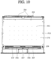
- FIGS. 9-11 illustrate example inner cases of a main body of a refrigerator.
- FIG. 12 illustrates an example metal plate of a main body of a refrigerator.
- FIG. 13 illustrates an example upper plate of a metal plate.
- FIG. 14 illustrates an example side plate of a metal plate.
- the inner case 200 may be formed in the box shape of which the front surface is opened.
- the inner case 200 may include an upper surface portion 210 which forms an upper surface thereof, two side surface portions 220 which are bent downward and extend from both side ends of the upper surface portion 210, a rear surface portion 230 which is bent downward and extends from a rear end of the upper surface portion 210, and a lower surface portion 240 which connects lower ends of the two side surface portions 220 with a lower end of the rear surface portion 230.
- the metal plate 300 may include an upper plate 310 which is coupled to an inner surface of the upper surface portion 210, and two side plates 320 which are coupled to inner surfaces of the two side surface portions 220, respectively.
- a plurality of coupling ribs 311, 312, 321 and 322 which are coupled into a plurality of coupling openings 212, 213, 221 and 232 formed at the inner case 200 may be formed at the upper plate 310 and the two side plates 320. Since, instead of openings, the plurality of coupling ribs 311, 312, 321 and 322 are formed at the metal plate 300 by bending protruding portions thereof, the openings of the metal plate 300 may be prevented from becoming rusty later due to the cooling air formed at the inside of the inner case 200 at which the metal plate 300 is installed.
- the upper surface portion 210 may include a plurality of injection holes 211, a first coupling opening 212, a second coupling opening 213, one or more first duct coupling openings 215, one or more second duct coupling openings 214, a grille fixing portion 216 and a grille insertion hole 217.
- Each of the plurality of injection holes 211 may be formed in an opening shape which passes through the upper surface portion 210, and a small amount of foaming agent may be injected therethrough.
- a space between a lower surface of the upper surface portion 210 and an upper surface of the upper plate 310 may be filled with the foaming agent. Due to the foaming agent, the upper surface of the upper plate 310 may be uniformly attached to the lower surface of the upper surface portion 210.
- the upper plate 310 is formed of a metallic material having a heavy weight, a center portion of the upper plate 310 may be sagged down due to gravity if the foaming agent is not provided. Therefore, by injecting the predetermined amount of foaming agent through the plurality of injection holes 211, the upper plate 310 may be firmly attached to the lower surface of the upper surface portion 210 without being sagged.
- the plurality of injection holes 211 may respectively have a size so that the foaming agent is not discharged to an outside when the small amount of foaming agent is injected therein. That is, each of the plurality of injection holes 211 may have the size in which the small amount of foaming agent injected into each of the plurality of injection holes 211 is prevented from being discharged again or leaking to the outside. Since the foaming agent has an adhesive material having predetermined viscosity, the foaming agent is not discharged again, as long as each of the plurality of injection holes 211 has a predetermined size.
- the foaming agent may maintain insulation of the inside of the refrigerator while being prevented from leaking to the outside, and may also firmly couple the upper plate 310 to the upper surface portion 210 of the inner case 200.
- One or more first coupling openings 212 may be formed at both sides of the upper surface portion 210. In some implementations, the one or more first coupling openings 212 may be formed at both sides of an upper surface of the upper surface portion 210 to be spaced apart at a predetermined distance in a direction of a border of a side surface thereof. In some implementations, the first coupling opening 212 may be an opening which extends long from a front side toward a rear side.
- One or more second coupling openings 213 may be formed at the rear end of the upper surface portion 210. In some implementations, the one or more second coupling openings 213 may be formed at the rear end of the upper surface of the upper surface portion 210 to be spaced apart at a predetermined distance in a direction of a border of the rear end thereof.
- the one or more first duct coupling openings 215 may be formed at positions which are spaced apart from a front end of the upper surface portion 210 at a predetermined distance, and one ends 601 of the one or more upper ducts 600 may be coupled therein.
- the one or more first duct coupling openings 215 may be formed at positions, which are spaced apart from the front end of the upper surface portion 210 at the predetermined distance, so as to have shapes corresponding to those of the one ends 601 of the upper duct 600.
- the one or more second duct coupling openings 214 may be formed at the rear end of the upper surface portion 210, and the other ends 602 of the one or more upper ducts 600 may be coupled therein.
- the one or more second duct coupling openings 214 may be formed at the rear end of the upper surface portion 210 to have shapes corresponding to those of the other ends 602 of the upper duct 600, such that the cooling air generated from the evaporator 700 in the inner case 200 is introduced therein.
- the rear end of the upper surface portion 210 of the inner case 200 may include a first surface 210a which is parallel with the ground, an upper surface bending portion 210b which is bent down from the first surface 210a, and an upper surface rear end portion 210c which extends horizontally backward from the upper surface bending portion 210b and of which one end is connected to an upper end of the rear surface portion 230.
- the one or more second duct coupling openings 214 may be formed at a part of the upper surface rear end portion 210c.
- the grille fixing portion 216 is disposed at a position of the upper surface which is spaced backward from the front end of the upper surface portion 210 at the first distance d, and has a groove formed at a lower portion thereof to provide a space in which the grille part 800 is fixed.
- one grille fixing portion 216 may be disposed at each of both side ends of the upper surface portion 210 which are spaced apart from the front end of the upper surface portion 210 at the first distance d, and may fix the grille part 800.
- the grille fixing portion 216 may be formed at a position which is spaced laterally from a portion, at which the one or more first duct coupling openings 215 are formed, at a predetermined distance.
- the grille insertion hole 217 is an opening in which a part of the grille part 800 is inserted, and a plurality of grille insertion holes 217 may be formed at positions of the upper surface portion 210, which are spaced backward from the front end of the upper surface portion 210 at the first distance d, to be spaced apart along a border of the front end of the upper surface portion 210.
- Each of the two side surface portions 220 includes a third coupling opening 221 and a recessed portion 222.
- One or more third coupling openings 221 may be formed at positions which are spaced apart from a front end of each of the two side surface portions 220. In some implementations, the one or more third coupling openings 221 may be formed at positions, which are spaced apart from the front end of each of the two side surface portions 220 at the first distance d, to be spaced apart at a predetermined distance along a border of the front end of each of the side surface portions 220, e.g., in a direction vertical to the ground.
- the recessed portion 222 may be formed at a part of an inner surface of each of the two side surface portions 220.
- each of the two side surface portions 220 is bent outward at a position which is spaced apart from the front end at the first distance d by a depth of a width of the side plate 320, and then bent backward again, and thus forms a space in which the side plate 320 is inserted, the recessed portion 222 is the space in which the side plate 320 is inserted.
- the rear surface portion 230 may include a first coupling groove 231.
- the first coupling groove 231 may be formed at a position of an inner surface of the rear surface portion 230 at which a part of a rear end of the side plate 320 is disposed. In some implementations, the first coupling groove 231 may be formed to be recessed backward and downward from an inner surface of the rear surface portion 230.
- the upper plate 310 of the metal plate 300 may be coupled to the inner surface of the upper surface portion 210 at a position which is spaced apart from the front end of the upper surface portion 210 at the first distance d or more.
- the upper plate 310 may be a plate of which a length from a front end to a rear end is shorter than that of the upper surface portion 210 of the inner case 200 from the front end to the rear end. This is to prevent interference between the front end of the upper plate 310 and the refrigerator door when the refrigerator door is closed.
- the upper plate 310 may include one or more first coupling ribs 311 and one or more second coupling ribs 312.
- the first coupling ribs 311 may be formed in hook shapes which protrude upward from both sides of the upper surface of the upper plate 310. In some implementations, the number of first coupling ribs 311 may correspond to that of the first coupling openings 212.
- first coupling ribs 311 may be formed to be spaced apart at a predetermined distance along borders of both side surfaces of the upper plate 310. In some implementations, the distance between the first coupling ribs 311 may be the same as that between the first coupling openings 212 formed at the upper surface portion 210.
- the first coupling ribs 311 may include first protruding portions 311a which protrude upward from both sides of the upper plate 310, and first bending portions 311b which are bent backward from the first protruding portions 311a.
- each of the first bending portions 311b may be bent at a predetermined angle toward a center of the upper plate 310, and a first reinforcing portion 311c which protrudes in an extension direction of the first bending portion 311b to provide strength for preventing the first bending portion 311b from being bent may be formed at one surface of a bent portion of the first bending portion 311b. This is to enable the first coupling ribs 311 to be coupled into the first coupling openings 212, and also to enable the first bending portions 311b to be prevented from being bent while being installed or separated. Detailed description of a coupling configuration will be provided later.
- the second coupling ribs 312 may protrude upward from the rear end of the upper surface of the upper plate 310, and may be formed in hook shapes having predetermined widths. Also, the number of second coupling ribs 312 may correspond to that of the second coupling openings 213, and may be formed to be spaced apart from each other in a predetermined distance along a border of the rear end of the upper plate 310. In some implementations, the distance between the second coupling ribs 312 may be the same as that between the second coupling openings 213 formed at the upper surface portion 210.
- the second coupling ribs 312 may include second protruding portions 312a which protrude upward from the rear end of the upper plate 310, and second bending portions 312b and 312c which are bent backward from the second protruding portions 312a.
- the second bending portions 312b and 312c may be elastically deformed and fitted when the second coupling ribs 312 are inserted into the second coupling openings 213.
- parts of the second bending portions 312b and 312c may include a plurality of bending portions.
- the second bending portions 312b and 312c may be bent backward from the protruding portion at a predetermined angle (312b), and then may be bent upward again at a predetermined angle (312c). Due to the plurality of bending portions, the second bending portions 312b and 312c may be elastically deformed up and down using the first protruding portion 312a as an axis.
- the two side plates 320 of the metal plate 300 may be coupled to the inner surfaces of the side surface portions 220 at positions which are spaced backward from front ends of the side surface portions 220.
- each of the two side plates 320 may be formed so that a length thereof between a front end and a rear end is shorter than that of each of the side surface portion 220 of the inner case 200 between a front end and a rear end by the first distance d. This is to prevent interference between the front ends of the two side plates 320 and the refrigerator door when the refrigerator door is closed.
- Each of the two side plates 320 includes one or more third coupling ribs 321 and one or more fourth coupling ribs 322.
- the third coupling ribs 321 may be formed in hook shapes which protrude outward from one surface at which the side plate 320 is coupled to the side surface portion 220.
- the number of third coupling ribs 321 may correspond to that of third coupling openings 221.
- the third coupling ribs 321 may be formed to be spaced apart from a front end of one surface of the side plate 320 along a border of the front end of the side plate 320 at a predetermined distance. In some implementations, the distance between the third coupling ribs 321 may be the same as that between the third coupling openings 221 formed at the side surface portion 220.
- Each of the third coupling ribs 321 may include a third protruding portion 321a which protrudes outward from one surface of the side plate 320, and a third bending portion 321b which is bent upward from the third protruding portion 321a. Also, an upper portion of the third bending portion 321b may be bent toward a rear of the side plate 320 at a predetermined angle. Therefore, the third coupling rib 321 may be coupled into the third coupling opening 221, and also the third bending portion 321b may be prevented from being bent. A coupling relationship between the third coupling rib 321 and the third coupling opening 221 will be described later.
- the fourth coupling rib 322 may protrude backward from the rear end of the side plate 320, and a part of the protruding portion may be bent laterally.
- the number of fourth coupling ribs 322 may correspond to that of the first coupling grooves 231.
- the fourth coupling ribs 322 may be formed to be spaced up and down from the rear ends of the side plates 320 at a predetermined distance. In some implementations, the distance between the fourth coupling ribs 322 may be the same as that between the first coupling grooves 231 formed at the inner surface of the rear surface portion 230.
- the fourth coupling ribs 322 may include a fourth protruding portion 322a which protrudes backward from the rear end of the side plate 320, and a fourth bending portion 322b which is bent laterally from the fourth protruding portion 322a.
- a vertical length of the fourth bending portion 322b may be longer than that of the fourth protruding portion 322a. This is to prevent a portion of the fourth bending portion 322b which is longer than the vertical length of the fourth protruding portion 322a from interfering with an inner surface of the first coupling groove 231 while being inserted into the first coupling groove 231, and thus to prevent the portion of the fourth bending portion 322b from being separated toward the outside.
- a lower portion of the fourth bending portion 322b may be bent backward at a predetermined angle. Therefore, the fourth bending portion 322b may be coupled to the inner surface of the first coupling groove 231, and may also be prevented from being bent.
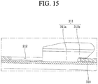
- FIG. 15 illustrates an example B portion of FIG. 5 .
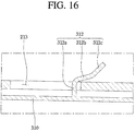
- FIG. 16 illustrates an example C portion of FIG. 5 .
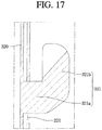
- FIG. 17 illustrates an example D portion of FIG. 5 .
- FIG. 18 illustrates an example A portion of FIG. 3 .
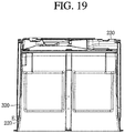
- FIG. 19 illustrates an example main body.
- FIG. 20 illustrates an example E portion of FIG. 19 .
- FIG. 21 illustrates an example a-a' portion of FIG. 8 .
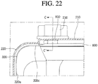
- FIG. 22 illustrates an example F portion of FIG. 21 .
- FIG. 23 illustrates an example c-c' portion of FIG. 22 .
- FIG. 24 illustrates an example b-b' portion of FIG. 8 .
- the first bending portion 311b of the first coupling rib 311 since the first bending portion 311b of the first coupling rib 311 is bent toward the center of the upper plate 310 at the predetermined angle, the first bending portion 311b may be inserted into the first coupling opening 212 through a bent inclined surface even when the first bending portion 311b interferes with the first coupling opening 212.
- the second bending portions 312b and 312c of the one or more second coupling ribs 312 are pressed by the lower surface of the upper surface portion 210, and thus temporarily elastically deformed downward.
- the upper plate 310 when the upper plate 310 is pushed backward, the first bending portions 311b of the first coupling ribs 311 are supported by a part of the upper surface of the upper surface portion 210, and the second bending portions 312b of the second coupling ribs 312 are fitted to the second coupling openings 213 while being elastically deformed upward, and thus the upper plate 310 is primarily coupled to the lower surface of the upper surface portion 210.
- the front end of the upper plate 310 is located at a position which is spaced apart from the front end of the upper surface portion 210 at the first distance d or more.
- the two side plates 320 are pushed toward the two side surface portions 220, the one or more third coupling ribs 321 formed at the front end of one surface of each of the side plates 320 are inserted into the one or more third coupling openings 221 formed at the front end of each of the side surface portions 220, respectively.
- the one or more fourth coupling ribs 322 formed at the rear end of each of the side plates 320 are inserted into the one or more first coupling grooves 231 formed at the inner surface of the rear surface portion 230, respectively, and thus the side plate 320 may be coupled to the side surface portions 220.
- lower ends of the side plates 320 may be supported by the partition wall which divides the refrigerator compartment and the freezer compartment in the inner case 200.
- a lower surface of each of the third protruding portions 321a of the third coupling ribs 321 and one surface of each of the third bending portions 321b are in contact with an inner circumferential surface of each of the third coupling openings 221 and a part of other surface of each of the side surface portions 220, respectively, and bent portions of the fourth bending portions 322b of the fourth coupling ribs 322 are inserted into lower sides of the first coupling grooves 231, and thus the side plates 320 are supported by the side surface portions 220.
- upper ends of the two side plates 320 may be supported at lower sides thereof by both side ends of the upper plate 310, respectively. That is, the both side ends of the upper plate 310 may be in contact with a lower surface of each of the upper ends of the two side plates 320, and thus the upper plate 310 may support the side plates 320.
- the upper plate 310 may include a first surface 310a which is disposed to be parallel with the upper surface portion 210 when being coupled to the upper surface portion 210 and shields the inner surface of the upper surface portion 210, and a side end portion 310d which is bent from both ends of the first surface 310a so as to be parallel with the first surface 310a and also to have an extension direction opposite to that of the first surface 310a.
- the first coupling rib 311 may be formed to extend upward from a distal end of the side end portion 310d.
- the side plate 320 may include a second surface 320a which is disposed to be parallel with the side surface portion 220 when being coupled to the side surface portion 220 and shields the inner surface of the side surface portion 220, and a upper end portion 320c which is bent from an upper end of the second surface 320a so as to correspond to the extending inner surfaces of the side surface portion 220 and the upper surface portion 210.
- the upper end portion 320c may include a first upper end portion 320d which is bent orthogonally from the second surface 320a and is parallel with the upper surface portion 210, a second upper end portion 320e which is bent upward from one end of the first upper end portion 320d, and a third upper end portion 320f which extends from the second upper end portion 320e in an extension direction of the first upper end portion 320d so as to be parallel with the first upper end portion 320d.
- the side end portion 310d of the upper plate 310 is disposed at a bending portion at which the third upper end portion 320f and the second upper end portion 320e are connected with each other, and thus the both side ends of the upper plate 310 may support the upper ends of the side plates 320 while the side end portion 310d supports a lower surface of the third upper end portion 320f.
- the grille part 800 may be disposed so that the rear end 820 is connected to the front end of the upper plate 310, and the front end 810 is connected to a front end of the inner case 200.
- the first grille protrusion portions 830 formed to protrude upward from upper surfaces of both sides of the grille part 800 may be respectively fitted to the grille fixing portions 216 disposed at the positions of the upper surfaces of both side ends which are spaced backward from the front end of the inner case 200 at the first distance d and having the groove formed at the lower portion thereof.
- a first groove 830a which is recessed inward may be formed at a part of an outer surface of each of the first grille protrusion portions 830, and a first protrusion 216a which has a shape corresponding to the first groove 830a may be formed at a groove formed at each of the grille fixing portions 216, e.g., a part of an inner surface of each of the grille fixing portions 216.
- the first grille protrusion portions 830 when the first grille protrusion portions 830 are fitted to the inner surfaces of the grille fixing portions 216, the first protrusions 216a are inserted into the first grooves 830a, and the first grille protrusion portions 830 are fixed to the grille fixing portions 216, and thus the grille part 800 may be coupled to the lower surface of the upper surface portion 210.
- the plurality of second grille protrusion portions 840 disposed between the two first grille protrusion portions 830 to be spaced apart at the regular intervals in a direction of a border of a front end of the grille part 800 are inserted into the plurality of grille insertion holes 217 formed at the upper surface portion 210 of the inner case 200, respectively, and thus the grille part 800 may be firmly fixed to the lower surface of the upper surface portion 210.
- a vertical gap may be formed between the rear end 820 of the grille part 800 and the lower surface of the upper surface portion 210, and the front end of the upper plate 310 may be in contact with and supported by an upper surface of the rear end 820 of the grille part 800.
- the upper plate 310 may include the first surface 310a, a first extending portion 310b which is bent upward and extends from a front end of the first surface 310a, and a first front end portion 310c which is bent forward from the first extending portion 310b to be parallel with the first surface 310a.
- the first front end portion 310c may be disposed at a spaced space between the rear end 820 of the grille part 800 and the lower surface of the upper surface portion 210. In some implementations, a lower surface of the first front end portion 310c may be seated on the upper surface of the rear end 820 of the grille part 800, and may be supported by the rear end 820 of the grille part 800.
- the side plates 320 are coupled to the side surface portions 220 by the third coupling ribs 321 and the fourth coupling ribs 322, and the lower ends thereof are seated on the partition wall, and the upper ends thereof are seated on and supported by the both side ends of the upper plate 310. Accordingly, the side plates 320 may be firmly coupled to the side surface portions 220, and may be prevented from being spaced by a load due to a weight of the metallic material.
- the upper plate 310 since the upper plate 310 is coupled to the upper surface portion 210 of the inner case 200 by the first coupling ribs 311, the second coupling ribs 312 and the foaming agent injected through the injection holes 211, and the front end thereof is seated on and supported by the rear end 820 of the grille part 800, the upper plate 310 may be firmly coupled to the upper surface portion 210, and may be prevented from being spaced or sagged by the load due to a weight of the metallic material. That is, the metal plate 300 may be in close contact with the inner surface of the inner case 200 by the coupling and the supporting.
- the recessed portion 222 which is recessed so that each of the side plates 320 is inserted therein when the side plates 320 are coupled may be formed at the inner surface of each of the two side surface portions 220.
- a recessed depth of the recessed portion 222 may be the same as a width of each of the side plates 320.
- the side plates 320 may be coupled to the side surface portions 220 while being inserted into the recessed portions 222 of the side surface portion 220.
- each of the side plates 320 may include a second front end portion 320b which is bent from the second surface 320a in a direction opposite to an extension direction of the second surface 320a so as to be parallel with the second surface 320a.
- an inner surface of the recessed portion 222 is in contact with one surface of the second front end portion 320b, and a space corresponding to a width of the second front end portion 320b is formed between the side plate 320 and the side surface portion 220.
- the space formed between the side plate 320 and the side surface portion 220 may be filled later with the foaming agent.
- the side plate 320 Since the side plate 320 is inserted into the recessed portion 222, and coupled to the side surface portion 220, the inner surface of the side surface portion 220 and the inner surface of the side plate 320 may extend smoothly without any bent portions or spaced portions. Therefore, the side plates 320 and the side surface portions 220 look as if being integrally formed with each other.
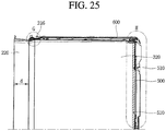
- FIG. 25 illustrates an example flow path in a refrigerator.
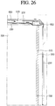
- FIG. 26 illustrates an example G portion.
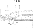
- FIG. 27 illustrates an example H portion.
- the one end 601 of the upper duct 600 may be coupled to the first duct coupling opening 215 formed at the upper surface portion 210 of the inner case 200, and the other end 602 thereof may be coupled to the second duct coupling opening 214.
- the cooling air may flow from the second duct coupling opening 214 to the first duct coupling opening 215 through the path.
- the grille part 800 may be disposed at a lower side of the first duct coupling opening 215 and the second duct coupling opening 214 to which the one end 601 of the upper duct 600 is coupled.
- the grille part 800 is coupled to the upper surface portion 210 of the inner case 200 has been already described, and thus will be omitted. Therefore, the cooling air guided from the second duct coupling opening 214 to the first duct coupling opening 215 may be supplied to the inside of the refrigerator through the grille part 800.
- the rear duct 500 may have a plate shape which is parallel with the rear surface portion 230 of the inner case 200, and may be disposed to be spaced forward from the rear surface portion 230 at a predetermined distance.
- the rear duct 500 may shield the inner surface of the rear surface portion 230 so as not to be seen from an outside, and may also provide a space, through which the cooling air flows, between the inner case 200 and the rear duct 500. Detailed configuration of the rear duct 500 has been already described, and thus will be omitted.
- the cooling air generated from the evaporator 700 is supplied to the space between the rear duct 500 and the inner case 200 by the multi-fan 900 disposed at the upper portion of the evaporator 700. Also, some of the cooling air supplied to the space between the rear duct 500 and the inner case 200 is discharged forward through the one or more discharge openings 510 formed at the rear duct 500, and thus supplied to the inside of the refrigerator.
- the remaining cooling air is moved to the second duct coupling opening 214 formed at the rear end of the upper surface portion 210 of the inner case 200, and then guided to the other end 602 of the upper duct 600 coupled to the second duct coupling opening 214.
- the cooling air guided to the other end 602 of the upper duct 600 is guided to the one end 601 of the upper duct 600 through the path formed in the upper duct 600, and discharged into the refrigerator through the first duct coupling opening 215 to which the one end 601 of the upper duct 600 is coupled and the grille part 800.
- the cooling air may be doubly supplied from a rear and a front of the inside of the refrigerator, and the stored product accommodated at the refrigerator door may receive sufficiently the cooling air, and thus the freshness thereof may be maintained.
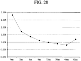
- FIG. 28 is a graph measuring the rate of increase in the insulation load according to a distance between the front end of the metal plate and the front end of the inner case of the refrigerator.
- An X axis in the graph is a length of the first distance, and a Y axis is a measured value of the rate of increase in the insulation load.
- the rate of increase in the insulation load is a rate of increase in a load for insulating external heat or preventing the internal cooling air from leaking to an outside. As the rate of increase in the insulation load becomes lower, heat insulation capacity is increased.
- the average rate of increase in the insulation load decreased.
- the average rate of increase in the insulation load was 1% or less, and when the length of the first distance d is 40 mm, the average rate of increase in the insulation load was 0.75%.
- the front end of the metal plate 300 is engaged with the refrigerator door as the distance between the front end of the metal plate 300 and the front end of the inner case 200 becomes narrower, and thus it may be confirmed that the cooling air preserved by the metal plate 300 leaks to the outside, and cooling efficiency of the refrigerator is degraded.
- the average rate of increase in the insulation load is increased again when the first distance d is 40 mm or more. In actual, it may be confirmed that the average rate of increase in the insulation load is more than 1.0% when the first distance d is 45 mm.
- Such a result may be confirmed by a fact that, when the distance between the front end of the metal plate 300 and the front end of the inner case 200 is a predetermined distance or more, an area of the metal plate 300 is reduced, and thus an amount of the cooling air preserved by the metal plate 300 is also reduced, and the heat insulation capacity is maintained, but the amount of the cooling air in the refrigerator is reduced.
- the heat insulation capacity is the most excellent when the first distance d is 12 to 40 mm.
- the refrigerator having the above-described configuration may have the following effects.
- the inside of the refrigerator is formed of a metallic material instead of a polymeric material, the inside of the refrigerator can be prevented from being stained or getting dirty while the user puts the stored product in the refrigerator or takes out the stored product therefrom, and also even when inside of the refrigerator is stained, the inside of the refrigerator can be cleaned.
- the metal plate itself is coupled to the inside of the refrigerator, instead that the metal material is plated, the metal material is prevented from being scraped off, and the entire beauty in the refrigerator is enhanced, and luminous efficiency in the refrigerator is increased due to a light reflecting property of the metal plate.
- the metal plate can be prevented from being rusty, or metal power can be prevented from falling down in the refrigerator.
- the foaming agent is injected into each of the plurality of injection holes formed at the upper plate, the foaming agent is injected into the space between the upper plate and the inner case, and thus the cooling efficiency is increased, and also the center of the upper plate can be prevented from being sagged by the load due to its own weight.
- the refrigerator compartment door or the freezer compartment door can be prevented from interfering with the metal plate while being closed, and the cooling air preserved by the metal plate can also be prevented from being discharged to the outside. Therefore, the amount of the cooling air in the refrigerator is increased, and the heat insulation capacity of the refrigerator can be substantially increased, and thus the stored product stored in the refrigerator can be maintained to be fresh.
- the duct is formed at the rear of the inner surface of the inner case, and the upper duct is additionally coupled to an upper portion of the inner case, the cooling air is doubly supplied from rear and upper sides of the inside of the refrigerator, and the cooling air is actively circulated in the refrigerator, and thus the stored product in the refrigerator can be stored freshly.
Landscapes
- Engineering & Computer Science (AREA)
- Physics & Mathematics (AREA)
- Mechanical Engineering (AREA)
- Thermal Sciences (AREA)
- General Engineering & Computer Science (AREA)
- Chemical & Material Sciences (AREA)
- Combustion & Propulsion (AREA)
- Cold Air Circulating Systems And Constructional Details In Refrigerators (AREA)
- Refrigerator Housings (AREA)
- Devices That Are Associated With Refrigeration Equipment (AREA)
Claims (13)
- Kühlschrank, der aufweist:ein Außengehäuse (100), das in Kastenform ausgebildet ist und eine Außenseite des Kühlschranks bildet; undein Innengehäuse (200), das innerhalb des Außengehäuses angeordnet ist und einen Lagerraum zum Lagern von Lebensmitteln bildet, wobei das Innengehäuse aufweist:einen Oberflächenabschnitt (210);zwei Seitenflächenabschnitte (220);einen Rückflächenabschnitt (230); undeinen Unterflächenabschnitt (240),wobei der Kühlschrank ferner eine Metallplatte (300) aufweist, die an einer Innenfläche des Innengehäuses angebracht ist, wobei die Metallplatte zwei Seitenplatten (320) aufweist, die innerhalb des Innengehäuses (200) angeordnet sind,wobei das Innengehäuse (200) einen ausgesparten Abschnitt (222) aufweist, der an jedem der beiden Seitenflächenabschnitte (220) gebildet ist,wobei der ausgesparte Abschnitt (222) ein Abschnitt jedes der beiden Seitenflächenabschnitte (220) ist, der an einer Position nach außen abgebogen ist, die von einem vorderen Ende davon beabstandet ist, und dann wieder nach hinten abgebogen ist, so dass eine jeweilige der beiden Seitenplatten (320) darin eingesetzt sein kann,wobei die Seitenplatte (320) aufweist:eine zweite Fläche (320a), die eine Innenfläche des Seitenflächenabschnitts (220) abschirmt; undeinen zweiten vorderen Endabschnitt (320b), der von einem vorderen Ende der zweiten Fläche (320a) nach hinten abgebogen ist, um parallel zur zweiten Fläche (320a) zu sein,dadurch gekennzeichnet, dassbeim Einsetzen der Seitenplatte (320) in den ausgesparten Abschnitt (222) eine Außenfläche des zweiten vorderen Endabschnitts (320b) in Kontakt mit einer Innenfläche des ausgesparten Abschnitts (222) steht,wobei der ausgesparte Abschnitt (222) in einer Tiefe ausgespart ist, die einer Breite zwischen dem zweiten vorderen Endabschnitt (320b) und der zweiten Fläche (320a) entspricht,wobei der Seitenflächenabschnitt (220) eine dritte Koppelöffnung (221) hat, die darin gebildet ist;wobei die Seitenplatte (320) eine dritte Koppelrippe (321) hat, die von einem vorderen Ende davon vorsteht, um in die dritte Koppelöffnung (221) eingesetzt zu sein,wobei die dritte Koppelrippe (321) aufweist:einen dritten Vorsprungabschnitt (321a), der von einem Ende des zweiten vorderen Endabschnitts (320b) der Seitenplatte (320) nach außen vorsteht; undeinen dritten Biegeabschnitt (321b), der vom dritten Vorsprungabschnitt (321a) nach oben abgebogen ist,wobei bei Kopplung der Seitenplatte (320) mit dem Innengehäuse (200) der dritte Vorsprungabschnitt (321a) in die dritte Koppelöffnung (221) eingesetzt ist.
- Kühlschrank nach Anspruch 1, wobei ein vorderes Ende jeder der beiden Seitenplatten (320) vom vorderen Ende eines jeweiligen der beiden Seitenflächenabschnitte (220) einen Abstand von 12 bis 40 mm hat.
- Kühlschrank nach Anspruch 1 oder 2, ferner mit einem Verdampfer (700), der im Innengehäuse (200) liegt und so konfiguriert ist, dass er Kaltluft erzeugt; und einem Gitterteil (800), das an der Innenfläche des Oberflächenabschnitts (210) angeordnet ist,wobei die Metallplatte (300) ferner eine obere Platte (310) aufweist, die mit einer Innenfläche des Oberflächenabschnitts (210) gekoppelt ist, undwobei ein vorderes Ende der oberen Platte (310) mit einem hinteren Ende des Gitterteils (800) verbunden ist.
- Kühlschrank nach Anspruch 3, der ferner aufweist:einen oberen Kanal (600), der außerhalb des Oberflächenabschnitts (210) angeordnet ist und ein Ende (601) hat, das mit dem Gitterteil (800) kommuniziert; undeinen hinteren Kanal (500), der innerhalb des Rückflächenabschnitts (230) angeordnet ist, um den Verdampfer (700) und das andere Ende (602) des oberen Kanals (600) zu verbinden,wobei ein vorderes Ende des Gitterteils (800) an einer Position angeordnet ist, die von einem vorderen Ende des Oberflächenabschnitts (210) beabstandet ist, um Kaltluft, die im Verdampfer (700) erzeugt wird, in das Innere des Innengehäuses (200) abzugeben.
- Kühlschrank nach Anspruch 3 oder 4, wobei die obere Platte (310) aufweist:eine erste Fläche (310a), die parallel zum Oberflächenabschnitt (210) ist;einen ersten Verlängerungsabschnitt (310b), der mit einem vorderen Ende der ersten Fläche verbunden ist und der zur selben Platte wie die erste Fläche gehört; undeinen ersten vorderen Endabschnitt (310c), der an einem Ende des ersten Verlängerungsabschnitts (310b) nach vorn abgebogen ist,wobei der erste vordere Endabschnitt (310c) auf einer Oberfläche eines hinteren Endes (820) des Gitterteils (800) angebaut ist, so dass die Oberfläche des hinteren Endes (820) des Gitterteils (800) so konfiguriert ist, dass sie eine Unterfläche des ersten vorderen Endabschnitts (310c) stützt.
- Kühlschrank nach einem der Ansprüche 3 bis 5, der ferner aufweist:Gittereinsetzlöcher (217), die im Oberflächenabschnitt (210) gebildet sind;Gittervorsprungabschnitte (830, 840), die von Oberflächen beider Seiten des Gitterteils (800) nach oben vorstehen und in die Gittereinsetzlöcher (217) eingesetzt sind; undGitterbefestigungsabschnitte (216), die mit einer Außenfläche der Gittervorsprungabschnitte (830, 840), die außerhalb des Innengehäuses (200) vorstehen, nach Durchlaufen der Gittereinsetzlöcher (217) gekoppelt sind, wobei die Gitterbefestigungsabschnitte (216) Vorsprünge (216a) aufweisen, die von Innenflächen davon vorstehen,wobei die Gittervorsprungabschnitte (830, 840) Nuten (830a) aufweisen, die von ihren Außenflächen nach innen ausgespart sind, undwobei die Vorsprünge (216a) in die Nuten (830a) eingesetzt sind, so dass das Gitterteil (800) an einer Unterseite der Oberfläche (210) des Innengehäuses (200) befestigt ist.
- Kühlschrank nach einem der Ansprüche 4 bis 6 soweit abhängig von Anspruch 4, wobei das Innengehäuse (200) aufweist:eine oder mehrere erste Kanalkoppelöffnungen (215), die in einem Bereich gebildet sind, der vom vorderen Ende des Oberflächenabschnitts (210) nach hinten beabstandet ist; undeine oder mehrere zweite Kanalkoppelöffnungen (214), die am hinteren Ende des Oberflächenabschnitts (210) gebildet sind,wobei das eine Ende (601) des oberen Kanals (600) mit der ersten Kanalkoppelöffnung (215) verbunden ist und das andere Ende (602) des oberen Kanals (600) mit der zweiten Koppelöffnung (214) verbunden ist.
- Kühlschrank nach Anspruch 7, wobei das Gitterteil (800) unter der einen oder den mehreren ersten Kanalkoppelöffnungen (215) liegt.
- Kühlschrank nach einem der Ansprüche 3 bis 8,wobei das Innengehäuse (200) eine erste Koppelöffnung (212) hat, die in seinem Oberflächenabschnitt (210) gebildet ist, undwobei die obere Platte (310) eine erste Koppelrippe (311) hat, die von einem Seitenende davon nach oben vorsteht, um in die erste Koppelöffnung (212) eingesetzt zu sein,wobei die erste Koppelrippe (311) aufweist:einen ersten Vorsprungabschnitt (311a), der von einem Seitenende der oberen Platte (310) nach oben vorsteht; undeinen ersten Biegeabschnitt (311b), der von den ersten Vorsprungabschnitten (311a) nach hinten abgebogen ist,wobei bei Kopplung der ersten Koppelrippe (311) mit der ersten Koppelöffnung (212) der erste Biegeabschnitt (311b) durch den Oberflächenabschnitt (210) des Innengehäuses (200) gestützt wird.
- Kühlschrank nach einem der Ansprüche 3 bis 9,wobei das Innengehäuse (200) eine zweite Koppelöffnung (213) hat, die in seinem Oberflächenabschnitt (210) gebildet ist; undwobei die obere Platte (310) eine zweite Koppelrippe (312) hat, die an einem hinteren Ende davon nach oben vorsteht, um in die zweite Koppelöffnung (213) eingesetzt zu sein,wobei die zweite Koppelrippe (312) aufweist:einen zweiten Vorsprungabschnitt (312a), der vom hinteren Ende der oberen Platte (310) nach oben vorsteht; undeinen zweiten Biegeabschnitt (312b, 312c), der vom zweiten Vorsprungabschnitt (312a) nach hinten abgebogen ist,wobei bei Kopplung der zweiten Koppelrippe (312) mit der zweiten Koppelöffnung (213) der zweite Biegeabschnitt (312b) durch den Oberflächenabschnitt (210) des Innengehäuses (200) gestützt wird.
- Kühlschrank nach einem der vorstehenden Ansprüche,wobei die Seitenplatte (320) einen vierten Vorsprungabschnitt (322a) hat, der von einem hinteren Ende davon nach hinten vorsteht; undwobei das Innengehäuse (200) eine Koppelnut (231) hat, die von einem Rückflächenabschnitt (230) davon nach hinten ausgespart ist,wobei bei Kopplung der Seitenplatte (320) mit dem Innengehäuse (200) die vierte Koppelrippe (322) in die Koppelnut (231) eingesetzt ist.
- Kühlschrank nach einem der Ansprüche 9 bis 11 soweit abhängig von Anspruch 9, wobei die obere Platte (310) aufweist:eine erste Oberfläche (310a), die eine Innenfläche des Oberflächenabschnitts (210) abschirmt; undSeitenendabschnitte (310d), die von beiden Seitenenden der ersten Fläche (310a) abgebogen sind und sich parallel zur ersten Fläche (310a) erstrecken,wobei jede der beiden Seitenplatten (320) aufweist:eine zweite Fläche (320a), die eine Innenfläche des Seitenflächenabschnitts (220) abschirmt; undeinen oberen Endabschnitt (320c), der von einem oberen Ende der zweiten Fläche (320a) abgebogen ist,wobei der obere Endabschnitt (320c) auf einer Oberfläche des Seitenendabschnitts (310d) angeordnet ist, um durch den Seitenendabschnitt (310d) gestützt zu werden,wobei der obere Endabschnitt (320c) aufweist:einen ersten oberen Endabschnitt (320d), der sich von der zweiten Fläche (320a) erstreckt;einen zweiten oberen Endabschnitt (320e), der von einem Ende des ersten oberen Endabschnitts (320d) abgebogen ist; undeinen dritten oberen Endabschnitt (320f), der von einem Ende des zweiten oberen Endabschnitts (320e) abgebogen ist,wobei der dritte obere Endabschnitt (320f) auf einer Oberfläche des Seitenendabschnitts (310d) angeordnet ist, um durch den Seitenendabschnitt (310d) gestützt zu werden.
- Kühlschrank nach einem der Ansprüche 4 bis 12 soweit abhängig von Anspruch 4, wobei der hintere Kanal (500) ein metallisches Material aufweist und eine oder mehrere Abgabeöffnungen (510) bildet, die so konfiguriert sind, dass sie Kaltluft in den Lagerraum abgeben.
Applications Claiming Priority (3)
| Application Number | Priority Date | Filing Date | Title |
|---|---|---|---|
| KR1020150120181A KR101872074B1 (ko) | 2015-08-26 | 2015-08-26 | 냉장고 |
| EP17203206.2A EP3321616B1 (de) | 2015-08-26 | 2016-08-24 | Kühlschrank |
| EP16185444.3A EP3144612B1 (de) | 2015-08-26 | 2016-08-24 | Kühlschrank |
Related Parent Applications (3)
| Application Number | Title | Priority Date | Filing Date |
|---|---|---|---|
| EP16185444.3A Division EP3144612B1 (de) | 2015-08-26 | 2016-08-24 | Kühlschrank |
| EP17203206.2A Division-Into EP3321616B1 (de) | 2015-08-26 | 2016-08-24 | Kühlschrank |
| EP17203206.2A Division EP3321616B1 (de) | 2015-08-26 | 2016-08-24 | Kühlschrank |
Publications (2)
| Publication Number | Publication Date |
|---|---|
| EP3553429A1 EP3553429A1 (de) | 2019-10-16 |
| EP3553429B1 true EP3553429B1 (de) | 2021-09-29 |
Family
ID=56799337
Family Applications (3)
| Application Number | Title | Priority Date | Filing Date |
|---|---|---|---|
| EP19171947.5A Active EP3553429B1 (de) | 2015-08-26 | 2016-08-24 | Kühlschrank |
| EP17203206.2A Active EP3321616B1 (de) | 2015-08-26 | 2016-08-24 | Kühlschrank |
| EP16185444.3A Active EP3144612B1 (de) | 2015-08-26 | 2016-08-24 | Kühlschrank |
Family Applications After (2)
| Application Number | Title | Priority Date | Filing Date |
|---|---|---|---|
| EP17203206.2A Active EP3321616B1 (de) | 2015-08-26 | 2016-08-24 | Kühlschrank |
| EP16185444.3A Active EP3144612B1 (de) | 2015-08-26 | 2016-08-24 | Kühlschrank |
Country Status (4)
| Country | Link |
|---|---|
| US (2) | US10386108B2 (de) |
| EP (3) | EP3553429B1 (de) |
| KR (1) | KR101872074B1 (de) |
| CN (1) | CN106482424B (de) |
Families Citing this family (6)
| Publication number | Priority date | Publication date | Assignee | Title |
|---|---|---|---|---|
| KR102344627B1 (ko) | 2017-07-31 | 2021-12-30 | 엘지전자 주식회사 | 냉장고 |
| US10677517B1 (en) * | 2019-06-28 | 2020-06-09 | Whirlpool Corporation | Cross member for an insulated structure |
| CN111197904A (zh) * | 2020-02-17 | 2020-05-26 | 海信容声(扬州)冰箱有限公司 | 一种冰箱及其箱体的制作方法 |
| EP4332477B1 (de) | 2021-09-10 | 2026-04-01 | Samsung Electronics Co., Ltd. | Kühlschrank |
| WO2025247229A1 (zh) * | 2024-05-27 | 2025-12-04 | 青岛海尔电冰箱有限公司 | 箱体和储物设备 |
| WO2025247029A1 (zh) * | 2024-05-27 | 2025-12-04 | 青岛海尔电冰箱有限公司 | 箱体和储物设备 |
Family Cites Families (33)
| Publication number | Priority date | Publication date | Assignee | Title |
|---|---|---|---|---|
| US2285947A (en) * | 1940-02-21 | 1942-06-09 | Westinghouse Electric & Mfg Co | Refrigeration apparatus |
| US2310117A (en) * | 1941-04-25 | 1943-02-02 | Gen Motors Corp | Refrigerating apparatus |
| US2432042A (en) * | 1945-10-15 | 1947-12-02 | Seeger Refrigerator Co | Refrigerator cabinet construction having means to restrict moisture in the walls of the cabinet |
| US2957320A (en) * | 1959-09-28 | 1960-10-25 | Gen Motors Corp | Refrigerating apparatus with magnetic door seal actuated switch |
| US3440308A (en) * | 1965-09-09 | 1969-04-22 | Gen Electric | Method of making a refrigerator cabinet assembly |
| US3872688A (en) * | 1974-06-13 | 1975-03-25 | Whirlpool Co | Refrigeration apparatus divider wall mounting means |
| US4369632A (en) * | 1979-12-07 | 1983-01-25 | Tyler Refrigeration Corporation | Refrigerated merchandiser display case |
| JPS616172U (ja) * | 1984-06-15 | 1986-01-14 | 株式会社富士通ゼネラル | 冷蔵庫 |
| JPS616172A (ja) | 1984-06-20 | 1986-01-11 | 株式会社日本製鋼所 | 射出成形用セラミツクス組成物 |
| FR2639424A1 (fr) * | 1988-11-24 | 1990-05-25 | Salaberry Bernard De | Meubles de conservation de produits par le froid |
| JPH0493973A (ja) | 1990-08-07 | 1992-03-26 | Canon Inc | 画像形成装置のクリーニング装置 |
| JPH07269779A (ja) * | 1994-03-28 | 1995-10-20 | Toshiba Corp | 断熱筐体及び真空断熱パネルの製造方法 |
| JPH0861824A (ja) * | 1994-08-26 | 1996-03-08 | Sanyo Electric Co Ltd | 冷却貯蔵庫 |
| US5784896A (en) * | 1996-10-18 | 1998-07-28 | White Consolidated Industries, Inc. | Freezer or refrigerator construction suitable for food service use |
| JP3540571B2 (ja) * | 1997-09-26 | 2004-07-07 | 三洋電機株式会社 | 冷蔵庫 |
| JP2001108359A (ja) | 1999-10-01 | 2001-04-20 | Matsushita Refrig Co Ltd | 冷蔵庫 |
| AUPQ459699A0 (en) * | 1999-12-09 | 2000-01-13 | Orford Pty Ltd | Improved airflow arrangement for a refrigerator |
| TW522213B (en) * | 2000-07-21 | 2003-03-01 | Fujitsu General Ltd | Electric refrigerator |
| US6422031B1 (en) * | 2001-08-15 | 2002-07-23 | Maytag Corporation | Refrigeration appliance with impingement cooling system |
| JP2003083664A (ja) * | 2001-09-07 | 2003-03-19 | Sanyo Electric Co Ltd | 冷蔵室の天面ダクト開閉機構 |
| JP4093973B2 (ja) | 2004-03-09 | 2008-06-04 | 三洋電機株式会社 | 冷蔵庫 |
| JP4869650B2 (ja) | 2005-07-28 | 2012-02-08 | ホシザキ電機株式会社 | 箱状組立体における板金結合構造 |
| JP2007064536A (ja) * | 2005-08-30 | 2007-03-15 | Hoshizaki Electric Co Ltd | 冷却貯蔵庫 |
| KR101327764B1 (ko) * | 2007-03-26 | 2013-11-12 | 엘지전자 주식회사 | 냉장고 |
| WO2008117911A1 (en) * | 2007-03-26 | 2008-10-02 | Lg Electronics Inc. | Reinforcing component for refrigerator |
| KR101541187B1 (ko) * | 2008-01-22 | 2015-08-06 | 엘지전자 주식회사 | 냉장고 |
| KR20100111481A (ko) * | 2009-04-07 | 2010-10-15 | 엘지전자 주식회사 | 냉장고 |
| US20130086936A1 (en) * | 2009-12-31 | 2013-04-11 | Lg Electronics Inc. | Refrigerator |
| JP5310929B1 (ja) * | 2012-06-20 | 2013-10-09 | パナソニック株式会社 | 断熱壁、断熱箱体及びその製造方法 |
| KR20140009647A (ko) * | 2012-07-12 | 2014-01-23 | 삼성전자주식회사 | 냉장고 및 냉장고의 제조방법 |
| US9132592B2 (en) * | 2012-11-19 | 2015-09-15 | General Electric Company | Appliance with expanding foam material |
| US9861213B2 (en) * | 2014-11-13 | 2018-01-09 | The Vollrath Company, L.L.C. | Forced cold air well with false bottom insert |
| US9593879B2 (en) * | 2015-03-17 | 2017-03-14 | Whirlpool Corporation | U-shaped tuck shelf |
-
2015
- 2015-08-26 KR KR1020150120181A patent/KR101872074B1/ko active Active
-
2016
- 2016-08-24 EP EP19171947.5A patent/EP3553429B1/de active Active
- 2016-08-24 EP EP17203206.2A patent/EP3321616B1/de active Active
- 2016-08-24 EP EP16185444.3A patent/EP3144612B1/de active Active
- 2016-08-26 CN CN201610730844.0A patent/CN106482424B/zh active Active
- 2016-08-26 US US15/248,096 patent/US10386108B2/en active Active
-
2019
- 2019-07-03 US US16/503,111 patent/US11346592B2/en active Active
Also Published As
| Publication number | Publication date |
|---|---|
| EP3321616B1 (de) | 2019-07-31 |
| CN106482424B (zh) | 2019-06-07 |
| US11346592B2 (en) | 2022-05-31 |
| EP3321616A1 (de) | 2018-05-16 |
| US20190323759A1 (en) | 2019-10-24 |
| US20170059229A1 (en) | 2017-03-02 |
| US10386108B2 (en) | 2019-08-20 |
| EP3144612A2 (de) | 2017-03-22 |
| EP3144612A3 (de) | 2017-06-14 |
| EP3144612B1 (de) | 2018-06-13 |
| KR20170024765A (ko) | 2017-03-08 |
| KR101872074B1 (ko) | 2018-06-27 |
| EP3553429A1 (de) | 2019-10-16 |
| CN106482424A (zh) | 2017-03-08 |
Similar Documents
| Publication | Publication Date | Title |
|---|---|---|
| EP3553429B1 (de) | Kühlschrank | |
| EP2175218B1 (de) | Kühlanlage | |
| KR101687897B1 (ko) | 냉장고 | |
| US20080202145A1 (en) | Refrigerator having reinforced receiving device | |
| JP2012063123A (ja) | 冷蔵庫 | |
| KR101979951B1 (ko) | 냉장고 | |
| KR101884588B1 (ko) | 냉장고 | |
| JP6715435B2 (ja) | 冷蔵庫 | |
| KR20100022742A (ko) | 냉장고 | |
| KR101902247B1 (ko) | 분리바 어셈블리가 구비된 냉장고 도어구조 및 이를 구비한 냉장고 | |
| JP2013057472A (ja) | 冷蔵庫 | |
| JP2012063122A (ja) | 冷蔵庫 | |
| JP3735463B2 (ja) | 貯蔵庫の配管構造 | |
| KR101432292B1 (ko) | 냉장고 | |
| CN108885053B (zh) | 冷藏库 | |
| US20240302093A1 (en) | Cooling device having a back cover | |
| EP1197713A1 (de) | Kühlschrank mit Innenauskleidung zur Lagerung von Lebensmitteln | |
| JP6294101B2 (ja) | 冷蔵庫 | |
| JP6371563B2 (ja) | 冷蔵庫 | |
| JP6554660B2 (ja) | 冷蔵庫 | |
| JP6839488B2 (ja) | 冷蔵庫 | |
| JP2013068389A (ja) | 冷蔵庫 | |
| JPH04116376A (ja) | 冷蔵庫 | |
| JP2018185061A (ja) | 冷蔵庫 | |
| JP2019011901A (ja) | 冷蔵庫 |
Legal Events
| Date | Code | Title | Description |
|---|---|---|---|
| PUAI | Public reference made under article 153(3) epc to a published international application that has entered the european phase |
Free format text: ORIGINAL CODE: 0009012 |
|
| STAA | Information on the status of an ep patent application or granted ep patent |
Free format text: STATUS: THE APPLICATION HAS BEEN PUBLISHED |
|
| AC | Divisional application: reference to earlier application |
Ref document number: 3144612 Country of ref document: EP Kind code of ref document: P Ref document number: 3321616 Country of ref document: EP Kind code of ref document: P |
|
| AK | Designated contracting states |
Kind code of ref document: A1 Designated state(s): AL AT BE BG CH CY CZ DE DK EE ES FI FR GB GR HR HU IE IS IT LI LT LU LV MC MK MT NL NO PL PT RO RS SE SI SK SM TR |
|
| STAA | Information on the status of an ep patent application or granted ep patent |
Free format text: STATUS: REQUEST FOR EXAMINATION WAS MADE |
|
| 17P | Request for examination filed |
Effective date: 20200416 |
|
| RBV | Designated contracting states (corrected) |
Designated state(s): AL AT BE BG CH CY CZ DE DK EE ES FI FR GB GR HR HU IE IS IT LI LT LU LV MC MK MT NL NO PL PT RO RS SE SI SK SM TR |
|
| GRAP | Despatch of communication of intention to grant a patent |
Free format text: ORIGINAL CODE: EPIDOSNIGR1 |
|
| STAA | Information on the status of an ep patent application or granted ep patent |
Free format text: STATUS: GRANT OF PATENT IS INTENDED |
|
| INTG | Intention to grant announced |
Effective date: 20210122 |
|
| GRAJ | Information related to disapproval of communication of intention to grant by the applicant or resumption of examination proceedings by the epo deleted |
Free format text: ORIGINAL CODE: EPIDOSDIGR1 |
|
| STAA | Information on the status of an ep patent application or granted ep patent |
Free format text: STATUS: REQUEST FOR EXAMINATION WAS MADE |
|
| GRAS | Grant fee paid |
Free format text: ORIGINAL CODE: EPIDOSNIGR3 |
|
| STAA | Information on the status of an ep patent application or granted ep patent |
Free format text: STATUS: GRANT OF PATENT IS INTENDED |
|
| INTC | Intention to grant announced (deleted) | ||
| GRAP | Despatch of communication of intention to grant a patent |
Free format text: ORIGINAL CODE: EPIDOSNIGR1 |
|
| INTG | Intention to grant announced |
Effective date: 20210709 |
|
| GRAA | (expected) grant |
Free format text: ORIGINAL CODE: 0009210 |
|
| STAA | Information on the status of an ep patent application or granted ep patent |
Free format text: STATUS: THE PATENT HAS BEEN GRANTED |
|
| AC | Divisional application: reference to earlier application |
Ref document number: 3144612 Country of ref document: EP Kind code of ref document: P Ref document number: 3321616 Country of ref document: EP Kind code of ref document: P |
|
| AK | Designated contracting states |
Kind code of ref document: B1 Designated state(s): AL AT BE BG CH CY CZ DE DK EE ES FI FR GB GR HR HU IE IS IT LI LT LU LV MC MK MT NL NO PL PT RO RS SE SI SK SM TR |
|
| REG | Reference to a national code |
Ref country code: GB Ref legal event code: FG4D |
|
| REG | Reference to a national code |
Ref country code: DE Ref legal event code: R096 Ref document number: 602016064510 Country of ref document: DE |
|
| REG | Reference to a national code |
Ref country code: CH Ref legal event code: EP Ref country code: AT Ref legal event code: REF Ref document number: 1434550 Country of ref document: AT Kind code of ref document: T Effective date: 20211015 |
|
| REG | Reference to a national code |
Ref country code: IE Ref legal event code: FG4D |
|
| REG | Reference to a national code |
Ref country code: LT Ref legal event code: MG9D |
|
| PG25 | Lapsed in a contracting state [announced via postgrant information from national office to epo] |
Ref country code: FI Free format text: LAPSE BECAUSE OF FAILURE TO SUBMIT A TRANSLATION OF THE DESCRIPTION OR TO PAY THE FEE WITHIN THE PRESCRIBED TIME-LIMIT Effective date: 20210929 Ref country code: RS Free format text: LAPSE BECAUSE OF FAILURE TO SUBMIT A TRANSLATION OF THE DESCRIPTION OR TO PAY THE FEE WITHIN THE PRESCRIBED TIME-LIMIT Effective date: 20210929 Ref country code: SE Free format text: LAPSE BECAUSE OF FAILURE TO SUBMIT A TRANSLATION OF THE DESCRIPTION OR TO PAY THE FEE WITHIN THE PRESCRIBED TIME-LIMIT Effective date: 20210929 Ref country code: BG Free format text: LAPSE BECAUSE OF FAILURE TO SUBMIT A TRANSLATION OF THE DESCRIPTION OR TO PAY THE FEE WITHIN THE PRESCRIBED TIME-LIMIT Effective date: 20211229 Ref country code: LT Free format text: LAPSE BECAUSE OF FAILURE TO SUBMIT A TRANSLATION OF THE DESCRIPTION OR TO PAY THE FEE WITHIN THE PRESCRIBED TIME-LIMIT Effective date: 20210929 Ref country code: NO Free format text: LAPSE BECAUSE OF FAILURE TO SUBMIT A TRANSLATION OF THE DESCRIPTION OR TO PAY THE FEE WITHIN THE PRESCRIBED TIME-LIMIT Effective date: 20211229 Ref country code: HR Free format text: LAPSE BECAUSE OF FAILURE TO SUBMIT A TRANSLATION OF THE DESCRIPTION OR TO PAY THE FEE WITHIN THE PRESCRIBED TIME-LIMIT Effective date: 20210929 |
|
| REG | Reference to a national code |
Ref country code: NL Ref legal event code: MP Effective date: 20210929 |
|
| REG | Reference to a national code |
Ref country code: AT Ref legal event code: MK05 Ref document number: 1434550 Country of ref document: AT Kind code of ref document: T Effective date: 20210929 |
|
| PG25 | Lapsed in a contracting state [announced via postgrant information from national office to epo] |
Ref country code: LV Free format text: LAPSE BECAUSE OF FAILURE TO SUBMIT A TRANSLATION OF THE DESCRIPTION OR TO PAY THE FEE WITHIN THE PRESCRIBED TIME-LIMIT Effective date: 20210929 Ref country code: GR Free format text: LAPSE BECAUSE OF FAILURE TO SUBMIT A TRANSLATION OF THE DESCRIPTION OR TO PAY THE FEE WITHIN THE PRESCRIBED TIME-LIMIT Effective date: 20211230 |
|
| PG25 | Lapsed in a contracting state [announced via postgrant information from national office to epo] |
Ref country code: AT Free format text: LAPSE BECAUSE OF FAILURE TO SUBMIT A TRANSLATION OF THE DESCRIPTION OR TO PAY THE FEE WITHIN THE PRESCRIBED TIME-LIMIT Effective date: 20210929 |
|
| PG25 | Lapsed in a contracting state [announced via postgrant information from national office to epo] |
Ref country code: IS Free format text: LAPSE BECAUSE OF FAILURE TO SUBMIT A TRANSLATION OF THE DESCRIPTION OR TO PAY THE FEE WITHIN THE PRESCRIBED TIME-LIMIT Effective date: 20220129 Ref country code: SK Free format text: LAPSE BECAUSE OF FAILURE TO SUBMIT A TRANSLATION OF THE DESCRIPTION OR TO PAY THE FEE WITHIN THE PRESCRIBED TIME-LIMIT Effective date: 20210929 Ref country code: RO Free format text: LAPSE BECAUSE OF FAILURE TO SUBMIT A TRANSLATION OF THE DESCRIPTION OR TO PAY THE FEE WITHIN THE PRESCRIBED TIME-LIMIT Effective date: 20210929 Ref country code: PT Free format text: LAPSE BECAUSE OF FAILURE TO SUBMIT A TRANSLATION OF THE DESCRIPTION OR TO PAY THE FEE WITHIN THE PRESCRIBED TIME-LIMIT Effective date: 20220131 Ref country code: PL Free format text: LAPSE BECAUSE OF FAILURE TO SUBMIT A TRANSLATION OF THE DESCRIPTION OR TO PAY THE FEE WITHIN THE PRESCRIBED TIME-LIMIT Effective date: 20210929 Ref country code: NL Free format text: LAPSE BECAUSE OF FAILURE TO SUBMIT A TRANSLATION OF THE DESCRIPTION OR TO PAY THE FEE WITHIN THE PRESCRIBED TIME-LIMIT Effective date: 20210929 Ref country code: ES Free format text: LAPSE BECAUSE OF FAILURE TO SUBMIT A TRANSLATION OF THE DESCRIPTION OR TO PAY THE FEE WITHIN THE PRESCRIBED TIME-LIMIT Effective date: 20210929 Ref country code: EE Free format text: LAPSE BECAUSE OF FAILURE TO SUBMIT A TRANSLATION OF THE DESCRIPTION OR TO PAY THE FEE WITHIN THE PRESCRIBED TIME-LIMIT Effective date: 20210929 Ref country code: CZ Free format text: LAPSE BECAUSE OF FAILURE TO SUBMIT A TRANSLATION OF THE DESCRIPTION OR TO PAY THE FEE WITHIN THE PRESCRIBED TIME-LIMIT Effective date: 20210929 Ref country code: AL Free format text: LAPSE BECAUSE OF FAILURE TO SUBMIT A TRANSLATION OF THE DESCRIPTION OR TO PAY THE FEE WITHIN THE PRESCRIBED TIME-LIMIT Effective date: 20210929 |
|
| REG | Reference to a national code |
Ref country code: DE Ref legal event code: R097 Ref document number: 602016064510 Country of ref document: DE |
|
| PG25 | Lapsed in a contracting state [announced via postgrant information from national office to epo] |
Ref country code: DK Free format text: LAPSE BECAUSE OF FAILURE TO SUBMIT A TRANSLATION OF THE DESCRIPTION OR TO PAY THE FEE WITHIN THE PRESCRIBED TIME-LIMIT Effective date: 20210929 |
|
| PLBE | No opposition filed within time limit |
Free format text: ORIGINAL CODE: 0009261 |
|
| STAA | Information on the status of an ep patent application or granted ep patent |
Free format text: STATUS: NO OPPOSITION FILED WITHIN TIME LIMIT |
|
| 26N | No opposition filed |
Effective date: 20220630 |
|
| PG25 | Lapsed in a contracting state [announced via postgrant information from national office to epo] |
Ref country code: SI Free format text: LAPSE BECAUSE OF FAILURE TO SUBMIT A TRANSLATION OF THE DESCRIPTION OR TO PAY THE FEE WITHIN THE PRESCRIBED TIME-LIMIT Effective date: 20210929 |
|
| PG25 | Lapsed in a contracting state [announced via postgrant information from national office to epo] |
Ref country code: MC Free format text: LAPSE BECAUSE OF FAILURE TO SUBMIT A TRANSLATION OF THE DESCRIPTION OR TO PAY THE FEE WITHIN THE PRESCRIBED TIME-LIMIT Effective date: 20210929 |
|
| REG | Reference to a national code |
Ref country code: CH Ref legal event code: PL |
|
| PG25 | Lapsed in a contracting state [announced via postgrant information from national office to epo] |
Ref country code: LU Free format text: LAPSE BECAUSE OF NON-PAYMENT OF DUE FEES Effective date: 20220824 Ref country code: LI Free format text: LAPSE BECAUSE OF NON-PAYMENT OF DUE FEES Effective date: 20220831 Ref country code: CH Free format text: LAPSE BECAUSE OF NON-PAYMENT OF DUE FEES Effective date: 20220831 |
|
| REG | Reference to a national code |
Ref country code: BE Ref legal event code: MM Effective date: 20220831 |
|
| PG25 | Lapsed in a contracting state [announced via postgrant information from national office to epo] |
Ref country code: IE Free format text: LAPSE BECAUSE OF NON-PAYMENT OF DUE FEES Effective date: 20220824 Ref country code: FR Free format text: LAPSE BECAUSE OF NON-PAYMENT OF DUE FEES Effective date: 20220831 |
|
| PG25 | Lapsed in a contracting state [announced via postgrant information from national office to epo] |
Ref country code: BE Free format text: LAPSE BECAUSE OF NON-PAYMENT OF DUE FEES Effective date: 20220831 |
|
| PG25 | Lapsed in a contracting state [announced via postgrant information from national office to epo] |
Ref country code: HU Free format text: LAPSE BECAUSE OF FAILURE TO SUBMIT A TRANSLATION OF THE DESCRIPTION OR TO PAY THE FEE WITHIN THE PRESCRIBED TIME-LIMIT; INVALID AB INITIO Effective date: 20160824 |
|
| PG25 | Lapsed in a contracting state [announced via postgrant information from national office to epo] |
Ref country code: SM Free format text: LAPSE BECAUSE OF FAILURE TO SUBMIT A TRANSLATION OF THE DESCRIPTION OR TO PAY THE FEE WITHIN THE PRESCRIBED TIME-LIMIT Effective date: 20210929 Ref country code: CY Free format text: LAPSE BECAUSE OF FAILURE TO SUBMIT A TRANSLATION OF THE DESCRIPTION OR TO PAY THE FEE WITHIN THE PRESCRIBED TIME-LIMIT Effective date: 20210929 |
|
| PG25 | Lapsed in a contracting state [announced via postgrant information from national office to epo] |
Ref country code: MK Free format text: LAPSE BECAUSE OF FAILURE TO SUBMIT A TRANSLATION OF THE DESCRIPTION OR TO PAY THE FEE WITHIN THE PRESCRIBED TIME-LIMIT Effective date: 20210929 |
|
| PG25 | Lapsed in a contracting state [announced via postgrant information from national office to epo] |
Ref country code: MT Free format text: LAPSE BECAUSE OF FAILURE TO SUBMIT A TRANSLATION OF THE DESCRIPTION OR TO PAY THE FEE WITHIN THE PRESCRIBED TIME-LIMIT Effective date: 20210929 |
|
| PGFP | Annual fee paid to national office [announced via postgrant information from national office to epo] |
Ref country code: DE Payment date: 20250707 Year of fee payment: 10 |
|
| PGFP | Annual fee paid to national office [announced via postgrant information from national office to epo] |
Ref country code: IT Payment date: 20250710 Year of fee payment: 10 |
|
| PGFP | Annual fee paid to national office [announced via postgrant information from national office to epo] |
Ref country code: GB Payment date: 20250707 Year of fee payment: 10 |
|
| PG25 | Lapsed in a contracting state [announced via postgrant information from national office to epo] |
Ref country code: TR Free format text: LAPSE BECAUSE OF FAILURE TO SUBMIT A TRANSLATION OF THE DESCRIPTION OR TO PAY THE FEE WITHIN THE PRESCRIBED TIME-LIMIT Effective date: 20210929 |