EP3566941B1 - Verbindungssystem für array-kabel von lösbaren offshore-energievorrichtungen - Google Patents
Verbindungssystem für array-kabel von lösbaren offshore-energievorrichtungen Download PDFInfo
- Publication number
- EP3566941B1 EP3566941B1 EP19185018.9A EP19185018A EP3566941B1 EP 3566941 B1 EP3566941 B1 EP 3566941B1 EP 19185018 A EP19185018 A EP 19185018A EP 3566941 B1 EP3566941 B1 EP 3566941B1
- Authority
- EP
- European Patent Office
- Prior art keywords
- floating
- connector system
- tube
- cable
- offshore energy
- Prior art date
- Legal status (The legal status is an assumption and is not a legal conclusion. Google has not performed a legal analysis and makes no representation as to the accuracy of the status listed.)
- Active
Links
Images


Classifications
-
- B—PERFORMING OPERATIONS; TRANSPORTING
- B63—SHIPS OR OTHER WATERBORNE VESSELS; RELATED EQUIPMENT
- B63B—SHIPS OR OTHER WATERBORNE VESSELS; EQUIPMENT FOR SHIPPING
- B63B22/00—Buoys
- B63B22/04—Fixations or other anchoring arrangements
-
- B—PERFORMING OPERATIONS; TRANSPORTING
- B63—SHIPS OR OTHER WATERBORNE VESSELS; RELATED EQUIPMENT
- B63B—SHIPS OR OTHER WATERBORNE VESSELS; EQUIPMENT FOR SHIPPING
- B63B1/00—Hydrodynamic or hydrostatic features of hulls or of hydrofoils
- B63B1/02—Hydrodynamic or hydrostatic features of hulls or of hydrofoils deriving lift mainly from water displacement
- B63B1/10—Hydrodynamic or hydrostatic features of hulls or of hydrofoils deriving lift mainly from water displacement with multiple hulls
- B63B1/107—Semi-submersibles; Small waterline area multiple hull vessels and the like, e.g. SWATH
-
- B—PERFORMING OPERATIONS; TRANSPORTING
- B63—SHIPS OR OTHER WATERBORNE VESSELS; RELATED EQUIPMENT
- B63B—SHIPS OR OTHER WATERBORNE VESSELS; EQUIPMENT FOR SHIPPING
- B63B22/00—Buoys
- B63B22/18—Buoys having means to control attitude or position, e.g. reaction surfaces or tether
-
- B—PERFORMING OPERATIONS; TRANSPORTING
- B63—SHIPS OR OTHER WATERBORNE VESSELS; RELATED EQUIPMENT
- B63B—SHIPS OR OTHER WATERBORNE VESSELS; EQUIPMENT FOR SHIPPING
- B63B35/00—Vessels or similar floating structures specially adapted for specific purposes and not otherwise provided for
- B63B35/44—Floating buildings, stores, drilling platforms, or workshops, e.g. carrying water-oil separating devices
- B63B2035/4433—Floating structures carrying electric power plants
- B63B2035/446—Floating structures carrying electric power plants for converting wind energy into electric energy
-
- B—PERFORMING OPERATIONS; TRANSPORTING
- B63—SHIPS OR OTHER WATERBORNE VESSELS; RELATED EQUIPMENT
- B63B—SHIPS OR OTHER WATERBORNE VESSELS; EQUIPMENT FOR SHIPPING
- B63B39/00—Equipment to decrease pitch, roll, or like unwanted vessel movements; Apparatus for indicating vessel attitude
- B63B39/06—Equipment to decrease pitch, roll, or like unwanted vessel movements; Apparatus for indicating vessel attitude to decrease vessel movements by using foils acting on ambient water
- B63B2039/067—Equipment to decrease pitch, roll, or like unwanted vessel movements; Apparatus for indicating vessel attitude to decrease vessel movements by using foils acting on ambient water effecting motion dampening by means of fixed or movable resistance bodies, e.g. by bilge keels
-
- F—MECHANICAL ENGINEERING; LIGHTING; HEATING; WEAPONS; BLASTING
- F03—MACHINES OR ENGINES FOR LIQUIDS; WIND, SPRING, OR WEIGHT MOTORS; PRODUCING MECHANICAL POWER OR A REACTIVE PROPULSIVE THRUST, NOT OTHERWISE PROVIDED FOR
- F03D—WIND MOTORS
- F03D13/00—Assembly, mounting or commissioning of wind motors; Arrangements specially adapted for transporting wind motor components
- F03D13/20—Arrangements for mounting or supporting wind motors; Masts or towers for wind motors
- F03D13/25—Arrangements for mounting or supporting wind motors; Masts or towers for wind motors specially adapted for offshore installation
-
- F—MECHANICAL ENGINEERING; LIGHTING; HEATING; WEAPONS; BLASTING
- F03—MACHINES OR ENGINES FOR LIQUIDS; WIND, SPRING, OR WEIGHT MOTORS; PRODUCING MECHANICAL POWER OR A REACTIVE PROPULSIVE THRUST, NOT OTHERWISE PROVIDED FOR
- F03D—WIND MOTORS
- F03D9/00—Adaptations of wind motors for special use; Combinations of wind motors with apparatus driven thereby; Wind motors specially adapted for installation in particular locations
- F03D9/20—Wind motors characterised by the driven apparatus
- F03D9/25—Wind motors characterised by the driven apparatus the apparatus being an electrical generator
- F03D9/255—Wind motors characterised by the driven apparatus the apparatus being an electrical generator connected to electrical distribution networks; Arrangements therefor
- F03D9/257—Wind motors characterised by the driven apparatus the apparatus being an electrical generator connected to electrical distribution networks; Arrangements therefor the wind motor being part of a wind farm
-
- F—MECHANICAL ENGINEERING; LIGHTING; HEATING; WEAPONS; BLASTING
- F05—INDEXING SCHEMES RELATING TO ENGINES OR PUMPS IN VARIOUS SUBCLASSES OF CLASSES F01-F04
- F05B—INDEXING SCHEME RELATING TO WIND, SPRING, WEIGHT, INERTIA OR LIKE MOTORS, TO MACHINES OR ENGINES FOR LIQUIDS COVERED BY SUBCLASSES F03B, F03D AND F03G
- F05B2240/00—Components
- F05B2240/90—Mounting on supporting structures or systems
- F05B2240/93—Mounting on supporting structures or systems on a structure floating on a liquid surface
-
- Y—GENERAL TAGGING OF NEW TECHNOLOGICAL DEVELOPMENTS; GENERAL TAGGING OF CROSS-SECTIONAL TECHNOLOGIES SPANNING OVER SEVERAL SECTIONS OF THE IPC; TECHNICAL SUBJECTS COVERED BY FORMER USPC CROSS-REFERENCE ART COLLECTIONS [XRACs] AND DIGESTS
- Y02—TECHNOLOGIES OR APPLICATIONS FOR MITIGATION OR ADAPTATION AGAINST CLIMATE CHANGE
- Y02E—REDUCTION OF GREENHOUSE GAS [GHG] EMISSIONS, RELATED TO ENERGY GENERATION, TRANSMISSION OR DISTRIBUTION
- Y02E10/00—Energy generation through renewable energy sources
- Y02E10/70—Wind energy
- Y02E10/72—Wind turbines with rotation axis in wind direction
-
- Y—GENERAL TAGGING OF NEW TECHNOLOGICAL DEVELOPMENTS; GENERAL TAGGING OF CROSS-SECTIONAL TECHNOLOGIES SPANNING OVER SEVERAL SECTIONS OF THE IPC; TECHNICAL SUBJECTS COVERED BY FORMER USPC CROSS-REFERENCE ART COLLECTIONS [XRACs] AND DIGESTS
- Y02—TECHNOLOGIES OR APPLICATIONS FOR MITIGATION OR ADAPTATION AGAINST CLIMATE CHANGE
- Y02E—REDUCTION OF GREENHOUSE GAS [GHG] EMISSIONS, RELATED TO ENERGY GENERATION, TRANSMISSION OR DISTRIBUTION
- Y02E10/00—Energy generation through renewable energy sources
- Y02E10/70—Wind energy
- Y02E10/727—Offshore wind turbines
Definitions
- the present invention relates to offshore energy converter units.
- the technology disclosed herein provides for a novel way to connect array cables to individual offshore energy converter units of an offshore energy farm.
- WO 20101093259 discloses a docking station 22 with cables 32 passing through a conduit 34 to a "manhole" access member 35. (page 2, lines 20-29.) Chambers 30 of docking station 22 are disclosed as being air-filled for buoyancy.
- the invention relates to the connection of array cables (for electric power connection and communications), between individual offshore energy converter (OEC) units of an offshore energy farm.
- OEC offshore energy converter
- the invention enables the quick disconnection and reconnection of each individual OEC unit, while keeping the flow of energy and information between adjacent OEC units.
- the disclosed subject matter relates to a floating connector of an offshore energy device.
- the floating connector includes a buoy having a long spar like floater, where the buoy provides buoyancy to the floating connector.
- the floating connector further includes at least two submarine cables for connecting to the offshore energy device.
- the floating connector also includes a joint box for coupling to the offshore energy device and for providing an electrical connection of the submarine cables to a switchgear of the offshore energy device. When the joint box is coupled to the offshore energy device, an electrical circuit with the at least two cables is completed through the offshore energy device via the switchgear.
- the disclosed subject matter also relates to a method for installing a floating connector system of an offshore energy converter device.
- Two cable ends of a pre-laid section of an array of cables are picked up from a seabed.
- the two cable ends are then connected inside the floating connector system.
- the connector system includes a buoy having a long spar like floater that provides buoyancy to the floating connector system.
- the connector system further includes at least two cables for connecting the offshore energy device to additional offshore energy converter devices.
- the connector system also includes a joint box for coupling to the offshore energy device and for providing an electrical connection of the at least two submarine cables to a switchgear of the offshore energy device. When the joint box is coupled to the offshore energy device, an electrical circuit with the at least two submarine cables is completed through the offshore energy device via the switchgear.
- the disclosed subject matter further relates to a floating connector of an offshore energy device that includes a buoy having a long spar like floater.
- the buoy provides buoyancy to the floating connector system.
- the floating connector further includes a single cable for connecting the offshore energy device to additional offshore energy converter devices.
- the floating connector also includes a joint box for coupling to the offshore energy device and for providing an electrical connection of the at least two cables to a switchgear of the offshore energy device. When the joint box is coupled to the offshore energy device, an electrical circuit with the at least two cables is completed through the offshore energy device via the switchgear.
- the single cable is used to connect a last offshore energy converter device to a string of offshore energy converter devices.
- the system employs a buoy, herein designated as a "floating I-Tube", consisting of a long spar like floater, which acts as an I-Tube to protect two array cables.
- a buoy herein designated as a "floating I-Tube”
- the floating I-Tube is attached to the renewable energy device, and two or more array cables are connected to the onboard switchgear, using disconnectable connectors.
- the concept allows the OEC unit to be removed from location (e.g., for operations and maintenance requirements) without losing the connection to other OEC units connected in series, thereby minimizing the production loss in the farm.
- the floating I-Tube may float in a location with two or more connected array cables and act as the station-keeping system.
- the invention also significantly reduces the connection and disconnection time, thereby allowing the OEC to be easily disconnected and towed to shore for maintenance operations. Having maintenance performed at shore helps avoid the need for specialized vessel used to perform offshore work.
- the invention also provides easy access to the electric cable ends at the deck level of the OEC.
- a disconnectable offshore wind energy generator is described in U.S. Patent No.: 8,729,723 B2 , "Removable Offshore Wind Turbines with Pre-Installed Mooring System,” which consists of a floating platform with two or more wind turbines, where the floating platform is connected to a second floater to which the mooring lines and array cable are connected.
- the platform supporting the wind generators is free to rotate around the mooring platform, according to the wind direction, much like the turrets used in floating production storage and offloading (FPSO) units used in the oil and gas industry.
- FPSO floating production storage and offloading
- FIGs 1a-1c depict an offshore energy farm layout, including station keeping system, array electric cable 110, shore cable 112, and OEC devices 102-108.
- removing OEC device 106 would mean the loss of connection with the OEC devices 102-104, which connected after the one which has been disconnected (i.e., OEC device 106), as shown in Figure 1b .
- the present invention would allow an OEC device to be removed while keeping the power flowing within the offshore renewable farm, as shown in Figure 1c , by using a floating buoy 114 to connect both array cables.
- the invention employs a floating I-Tube 202, capable of supporting two or more electric cables 204 connected to each renewable energy device.
- the floater may simply be disconnected from the platform and lowered to the sea level.
- the electric cables may act as the station keeping system for this floater, when the OEC is disconnected and towed onshore to be repaired.
- the I-Tube may be pulled back to the platform and rigidly connected to it to act as a permanent I-Tube. This system ensures that even if the platform is removed, the power is still flowing to the adjacent turbines.
- the invention can be applied to the last renewable energy device in a string of devices.
- a single cable may run through the I-Tube, and connect the device to the grid.
- the I-Tube is left in place, thus leaving the electric cable floating at the surface level.
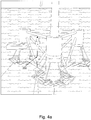
- the floating I-Tube 202 is rigidly attached to the OEC 302 during normal operation.
- the floating I-Tube 202 In order to disconnect the I-Tube 202 from the platform 304, the floating I-Tube 202 would be lowered to its floating draft, as shown in Figures 4a-4b , and then pulled away from the OEC with a small support vessel. This would only be necessary while the OEC station keeping system is being disconnected.
- the floater is designed to support two or more electric cables while the OEC is onshore for operations and maintenance activities. Prior to deployment, an enclosed bay of the floating I-Tube could be pressurized to guarantee the required buoyancy.
- the platform can be brought to location and hooked-up to its mooring system.
- the disconnection process is then reversed, and the I-Tube floater can be pushed back to the platform with a small vessel.
- Fenders located at the bottom of the OEC would guide the buoy into place, restraining the motion of the floating I-Tube.
- a winch onboard the OEC may be used to pull-up the floater, which would require a tension below 15 tons for shallow water locations. The tension requirements, however, may vary depending on the water depth.
- a joint box may be employed. At least one joint box will be located on the floating I-Tube.
- the two or more submarine cables 502 are connected to the pre-wired OEC cable 504 connected to the OEC switch gear on the joint box 506 at the top of the I-Tube, as show in Figure 5a .
- the joint box 506 would allow for the quick disconnection and reconnection of the conductors by using industry standard separable electrical connectors.
- the two submarine cables 502 running through the I-Tube are connected to the cable 504 coming from the switchgear onboard the OEC unit. If the OEC needs to be taken out, the cable 504 coming from the OEC switchgear is disconnected from the joint box 506 onboard the floating I-Tube. In this condition the power can flow between the two adjacent OECs, and the I-Tube is ready to be deployed, as shown in Figure 5b .
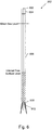
- FIG. 6 presents the components of the floating I-Tube 202.
- the floating I-Tube 202 includes lifting pad eye 602 enclosed bay 604, I-Tube 606, and bell-mouths 608.
- the lifting pad eye 602 provides a means for handling the I-Tube 202 during connection and disconnection to the OEC (e.g., lifting the I-Tube to the OEC). It also facilitates the removal of the cover of the enclosed bay 604 for maintenance access to the electric connectors.
- This enclosed bay 604 provides the required protection to the cable electric connectors during normal production and floating case.
- the relative dimensions of the floating I-Tube may vary. As seen in Figure 7 , which depicts the floating I-Tube joint boxes and electrical connections, the size of the connectors as well as the minimum bending radius of the connectors will drive the overall size of the arrangement.
- I-Tube 606 in Figure 6 protects the electric cables from the hang-offs at the exit of the bell-mouth 608.
- the I-Tube 606 and the enclosed bay 604 can be manufactured out of standard steel pipes, using air sealed flanges to guarantee the air-tightness of the floating I-Tube. Typical dimensions may vary between 0.6 to 1.5 m in diameter, with a length dependent on the design of the OEC.
- the enclosed bay 604 and I-Tube 606 can be pressurized to drop the water level below the mean floatation level of the floating I-Tube. The remaining water level inside the I-Tube will contribute to stabilize the I-Tube in Floatation mode.
- the bell mouth tubes provide the connection point for the bending stiffeners 610 at the cable exiting points.
- FIG. 7 shows the floating I-Tube 202, joint box 506 and electrical connectors 702 when connected to the OEC.
- the cover 704 of the enclosed bay can be lifted to provide access the electric connectors 702, thereby allowing for operations and maintenance operations.
- the cover 704 of the enclosed bay can be stored on the deck 708 during the duration of the operations. After completion of the works, the enclosed bay is covered again to protect the electric connections.
- the A-Frame 706 on the top of the I-Tube is used to connect it to the platform, open the enclosed bay and pull the electric cables through the I-tube during installation.
- sufficient buoyancy may not be provided by I-Tube 202, and thus an additional floater section 802 may be necessary, as shown in Figure 8a .
- a submerged design could be employed, like seen in Figure 8b .
- the electric cables 204 are connected directly to the platform level.
- the buoy 804 may be fully submerged and float at an intermediate equilibrium position in the water column.
- the invention enables two possible installation methods, according to which the array cables can be pre-laid before the OEC units are installed, or post-laid, after the OEC's are connected to their station keeping system.
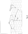
- FIG. 9 shows pre-laid array cables 902 for offshore energy farms.
- This installation method would start by pre-laying all the sections of the array cable on the seabed. Two cable ends would be deployed close to the location of each OEC. Using an anchor handling vessel to carry the floating I-Tube 202, the two cable ends would be picked up from the seabed and connected inside the floating I-Tube 202.
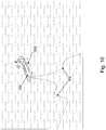
- Figure 10 shows the deployment of the floating I-Tube 202 from an offshore anchor handling vessel 1002 during pre-laying operations of the array cables 902 of an offshore energy farm. The anchor handling vessel would then deploy the floating I-Tube 202 on the location of the first OEC of the offshore energy farm, and then move to the next OEC location to repeat the process and install a new floating I-Tube.
- the OEC unit could then be transported to location. Once secured to its station keeping system, the floating I-Tube would be coupled to the OEC unit by the means described above.
- the array cables may also been post-laid, for example, after the OEC's are installed in their locations and connected to their station keeping systems.
- the floating I-Tubes 202 could be already connected to the OEC during its final assembly stage onshore.
- the array cables 902 could then be installed like in the case of a fixed I-Tube, using a pulling head and a guide-wire to pull the electric cable from the OEC, as shown in Figure 11 .
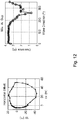
- the floating I-Tube when disconnected from the OEC unit, is designed to survive a variety of environmental conditions at its site. The design was studied for a specific location during a 1-year storm event in its floating condition (as depicted in Figure 2 ).
- the numerical code, OrcaFlex was used to analyze the floating I-Tube, taking into account hydrodynamic loads due to wave and current on the structure. Irregular waves with a Joint North Sea Wave Observation Project (JONSWAP) spectrum were considered, with significant wave heights that varied from 3 to 7.65 meters, with a wave period of 13.6 seconds.
- JONSWAP Joint North Sea Wave Observation Project
- a summary of the results is show in Figure 12 .
- the metrics described above is not representative of an exhaustive list of characteristics that may be analyzed as other metrics may be incorporated. Additionally, the metrics may be used individually or in combination with one another. Thus, the example illustrating the use of technology disclosed herein should not be taken as limiting or preferred. The examples provided above are merely used to illustrate the technology disclosed without being overly complicated. It is not intended to illustrate all of the technologies disclosed.
- the disclosed subject matter further relates to a floating connector of an offshore energy device.
- the floating connector includes a buoy having a long spar like floater, where the buoy provides buoyancy to the floating connector.
- the floating connector further includes at least two submarine cables for connecting to the offshore energy device.
- the floating connector also includes a joint box for coupling to the offshore energy device and for providing an electrical connection of the submarine cables to a switchgear of the offshore energy device. When the joint box is coupled to the offshore energy device, an electrical circuit with the at least two cables is completed through the offshore energy device via the switchgear.
- the floating connector may include a lifting pad eye disposed at the top of the spar like floater, where the lifting pad eye provides an attachment point to which a winch may attach in order to lift the floating connector system.
- the buoy and joint box may be disposed in an enclosed bay housing the joint box and the at least two cables.
- the enclosed bay may contain pressurized air to control the buoyancy of the floating connector system, and the air may be pressurized to a level such that the floating connector system is fully submerged and floating at an intermediate equilibrium position in a water column.
- the floating connector system may include one or more bell mouths disposed at the bottom of the spar like floater.
- the bell mouth provides an attachment point for a bending stiffener.
- the bending stiffener extends from the one or more bell mouths at the bottom of the spar like floater and provides rigidity to a section of each of the at least two cables covered by the bending stiffeners.
- At least two cables When the at least two cables are electrically connected to the switchgear of the offshore energy device, energy generated by the offshore energy converter device is transmittable from the offshore energy converter device to the at least two cables. At least one of the at least two cables may be electrically connected to a shore cable, where the shore cable transmits energy generated by the offshore energy converter device to shore.
- the buoy may include an extra floater to provide additional buoyancy.
- an electrical circuit is completable by connecting any pair of the at least two cables to each other.
- the offshore energy converter device, to which the floating connector system is coupled may also be connected to one or more mooring lines to ensure station keeping.
- a method for installing a floating connector system of an offshore energy converter device is also disclosed.
- Two cable ends of a pre-laid section of an array of cables are picked up from a seabed.
- the two cable ends are then connected inside the floating connector system.
- the connector system includes a buoy having a long spar like floater that provides buoyancy to the floating connector system.
- the connector system further includes at least two cables for connecting the offshore energy device to additional offshore energy converter devices.
- the connector system also includes a joint box for coupling to the offshore energy device and for providing an electrical connection of the at least two submarine cables to a switchgear of the offshore energy device. When the joint box is coupled to the offshore energy device, an electrical circuit with the at least two submarine cables is completed through the offshore energy device via the switchgear.
- the method further includes deploying the floating connector system when the two cable ends are connected inside the floating connector system.
- the floating connector system further includes a lifting pad eye disposed at the top of the spar like floater, where the lifting pad eye providing an attachment point to which a winch may attach in order to lift the floating connector system.
- the buoy and joint box of the floating connector system may be disposed in an enclosed bay housing the joint box and the at least two cables.
- the enclosed bay contains pressurized air to control the buoyancy of the floating connector system.
- the enclosed bay may contain air pressurized to a level such that the floating connector system, when deployed, is fully submerged and floating at an intermediate equilibrium position in a water column.
- At least two cables when the at least two cables are electrically connected to the switchgear of the offshore energy device, energy generated by the offshore energy converter device is transmittable from the offshore energy converter device to the at least two cables.
- At least one of the at least two cables may be electrically connected to a shore cable, where the shore cable transmits energy generated by the offshore energy converter device to shore.
- the floating connector system is secured to the offshore energy converter device when the two cable ends are connected inside the floating connector system. In some embodiments, the floating connector system is aboard an anchor handling vessel when the two cable ends are connected inside the floating connector system.
- the disclosed subject matter further relates to a floating connector of an offshore energy device that includes a buoy having a long spar like floater.
- the buoy provides buoyancy to the floating connector system.
- the floating connector further includes a single cable for connecting the offshore energy device to additional offshore energy converter devices.
- the floating connector also includes a joint box for coupling to the offshore energy device and for providing an electrical connection of the at least two cables to a switchgear of the offshore energy device. When the joint box is coupled to the offshore energy device, an electrical circuit with the at least two cables is completed through the offshore energy device via the switchgear.
- the single cable is used to connect a last offshore energy converter device to a string of offshore energy converter devices.
Landscapes
- Chemical & Material Sciences (AREA)
- Engineering & Computer Science (AREA)
- Ocean & Marine Engineering (AREA)
- Combustion & Propulsion (AREA)
- Mechanical Engineering (AREA)
- Fluid Mechanics (AREA)
- Physics & Mathematics (AREA)
- Chemical Kinetics & Catalysis (AREA)
- Other Liquid Machine Or Engine Such As Wave Power Use (AREA)
- Laying Of Electric Cables Or Lines Outside (AREA)
- Supply And Distribution Of Alternating Current (AREA)
- Architecture (AREA)
- Civil Engineering (AREA)
- Structural Engineering (AREA)
Claims (14)
- Schwimmendes Verbindersystem einer Offshore-Energiewandlervorrichtung, wobei das System Folgendes umfasst:ein schwimmendes Rohr (202), das dem schwimmenden Verbindersystem Auftriebskraft bereitstellt;mindestens ein Kabel (204) zum Verbinden der Offshore-Energievorrichtung mit zusätzlichen Offshore-Energiewandlervorrichtungen, wobei das mindestens eine Kabel (204) von einem unteren Ende in das Innere des schwimmenden Rohrs (202) eintritt und zum oberen Ende verläuft; undeine Kabelmuffe (506) zum Koppeln an die Offshore-Energievorrichtung und zum Bereitstellen einer elektrischen Verbindung des mindestens einen Kabels (204) mit einer Schalteinrichtung der Offshore-Energievorrichtung,wobei das schwimmende Rohr (202) eine erste Konfiguration, in der das schwimmende Rohr (202) an einem oberen Ende luftdicht ist, wodurch die Auftriebskraft bereitgestellt wird, und eine zweite Konfiguration, in der ein Inneres des schwimmenden Rohrs (202) am oberen Ende zugänglich ist und das schwimmende Rohr (202) am oberen Ende nicht luftdicht ist, aufweist, wobei die Kabelmuffe (506) an dem oberen Ende des schwimmenden Rohrs (202) angeordnet und nur in der zweiten Konfiguration zugänglich ist, wenn die Kabelmuffe (506) an die Offshore-Energievorrichtung gekoppelt ist und sich das schwimmende Rohr (202) in der zweiten Konfiguration befindet, wobei ein elektrischer Schaltkreis mit dem mindestens einen Kabel (204) durch die Offshore-Energievorrichtung über die Schalteinrichtung vervollständigt sein kann und wobei, wenn die Kabelmuffe (506) von der Offshore-Energievorrichtung gelöst ist und sich das schwimmende Rohr (202) in der ersten Konfiguration befindet und von der Offshore-Energievorrichtung ausgebracht ist, an dem oberen Ende des schwimmenden Rohrs (202) zurückgehaltene Luft die Hauptquelle der Auftriebskraft für das schwimmende Verbindersystem bereitstellt.
- Schwimmendes Verbindersystem nach Anspruch 1, ferner umfassend ein Hubdeckauge (602), das an der Oberseite des schwimmenden Rohrs (202) angeordnet ist, wobei das Hubdeckauge (202) einen Befestigungspunkt bereitstellt, an dem eine Winde befestigt werden kann, um das schwimmende Verbindersystem zu heben.
- Schwimmendes Verbindersystem nach Anspruch 1, wobei ein umschlossener Schacht (604) die Kabelmuffe (506) aufnimmt und das mindestens eine Kabel (204) und der umschlossene Schacht (604) das obere Ende des schwimmenden Rohrs (202) abdichten, wenn sich das schwimmende Rohr (202) in der ersten Konfiguration befindet.
- Schwimmendes Verbindersystem nach Anspruch 3, wobei der umschlossene Schacht (604) druckbeaufschlagte Luft enthält, die Auftriebskraft für das schwimmende Verbindersystem bereitstellt, wenn die Kabelmuffe (506) von der Offshore-Energievorrichtung gelöst ist und das schwimmende Rohr (202) von der Offshore-Energievorrichtung ausgebracht ist.
- Schwimmendes Verbindersystem nach Anspruch 4, wobei der umschlossene Schacht (604) Luft enthält, die auf ein Niveau druckbeaufschlagt ist, sodass das schwimmende Verbindersystem vollständig untergetaucht ist und mit einer mittleren Ausgleichsposition in einer Wassersäule schwimmt.
- Schwimmendes Verbindersystem nach Anspruch 1, ferner umfassend eine oder mehrere Aufwerfungen (608), die an der Unterseite des Rohrs (606) angeordnet sind, wobei die Aufwerfung einen Befestigungspunkt für ein sich biegendes Versteifungselement (610) bereitstellt.
- Schwimmendes Verbindersystem nach Anspruch 6, wobei sich das sich biegende Versteifungselement (610) von der Aufwerfung (608) an der Unterseite des Rohrs (606) erstreckt und einem Abschnitt eines von dem mindestens einen Kabel (204), das durch das sich biegende Versteifungselement (610) bedeckt ist, Steifigkeit bereitstellt.
- Schwimmendes Verbindersystem nach Anspruch 1, wobei die durch die Offshore-Energiewandlervorrichtung generierte Energie von der Offshore-Energiewandlervorrichtung zu dem mindestens einen Kabel (204) übertragbar ist, wenn das mindestens eine Kabel (204) elektrisch mit der Schalteinrichtung der Offshore-Energievorrichtung verbunden ist.
- Schwimmendes Verbindersystem nach Anspruch 1, wobei mindestens eines von dem mindestens einen Kabel (204) elektrisch mit einem Landkabel verbunden ist, wobei das Landkabel durch die Offshore-Energiewandlervorrichtung generierte Energie an Land überträgt.
- Schwimmendes Verbindersystem nach Anspruch 1, wobei das schwimmende Rohr (202) einen zusätzlichen Schwimmer (802) beinhaltet, um zusätzliche Auftriebskraft bereitzustellen.
- Schwimmendes Verbindersystem nach Anspruch 1, wobei das mindestens eine Kabel (204) von der Schalteinrichtung gelöst ist, wenn die Kabelmuffe (506) von der Offshore-Energievorrichtung abgekoppelt ist, und mindestens zwei Kabel (204) vorhanden sind, wobei ein elektrischer Schaltkreis durch Verbinden von zwei Kabeln der mindestens zwei Kabel miteinander vervollständigt sein kann.
- Schwimmendes Verbindersystem nach Anspruch 1, wobei die Offshore-Energiewandlervorrichtung, an die das schwimmende Verbindersystem gekoppelt ist, mit einem oder mehreren Ankertauen verbunden ist, um Lagestabilität sicherzustellen.
- Verfahren zum Installieren eines schwimmenden Verbindersystems nach einem der Ansprüche 1-12, wobei das Verfahren Folgendes umfasst:Aufnehmen eines Endes des mindestens einen Kabels (204) eines vorab ausgelegten Abschnitts eines Arrays von Kabeln (204) von einem Meeresboden; undVerbinden des Endes des mindestens einen Kabels (204) innerhalb des schwimmenden Verbindersystems.
- Verfahren nach Anspruch 13, ferner umfassend, wenn zwei Kabel (204) vorhanden sind:
Ausbringen des schwimmenden Verbindersystems, wobei die zwei Kabelenden innerhalb des schwimmenden Verbindersystems verbunden sind.
Priority Applications (1)
| Application Number | Priority Date | Filing Date | Title |
|---|---|---|---|
| PL19185018T PL3566941T3 (pl) | 2014-10-27 | 2015-10-27 | System połączeń dla przewodów sieciowych odłączalnych morskich urządzeń energetycznych |
Applications Claiming Priority (3)
| Application Number | Priority Date | Filing Date | Title |
|---|---|---|---|
| US201462069235P | 2014-10-27 | 2014-10-27 | |
| EP15856048.2A EP3212496B1 (de) | 2014-10-27 | 2015-10-27 | Verbindungssystem für array-kabel von lösbaren offshore-energievorrichtungen |
| PCT/US2015/057636 WO2016069636A2 (en) | 2014-10-27 | 2015-10-27 | Connection system for array cables of disconnectable offshore energy devices |
Related Parent Applications (2)
| Application Number | Title | Priority Date | Filing Date |
|---|---|---|---|
| EP15856048.2A Division EP3212496B1 (de) | 2014-10-27 | 2015-10-27 | Verbindungssystem für array-kabel von lösbaren offshore-energievorrichtungen |
| EP15856048.2A Division-Into EP3212496B1 (de) | 2014-10-27 | 2015-10-27 | Verbindungssystem für array-kabel von lösbaren offshore-energievorrichtungen |
Publications (2)
| Publication Number | Publication Date |
|---|---|
| EP3566941A1 EP3566941A1 (de) | 2019-11-13 |
| EP3566941B1 true EP3566941B1 (de) | 2021-09-01 |
Family
ID=55791376
Family Applications (2)
| Application Number | Title | Priority Date | Filing Date |
|---|---|---|---|
| EP15856048.2A Active EP3212496B1 (de) | 2014-10-27 | 2015-10-27 | Verbindungssystem für array-kabel von lösbaren offshore-energievorrichtungen |
| EP19185018.9A Active EP3566941B1 (de) | 2014-10-27 | 2015-10-27 | Verbindungssystem für array-kabel von lösbaren offshore-energievorrichtungen |
Family Applications Before (1)
| Application Number | Title | Priority Date | Filing Date |
|---|---|---|---|
| EP15856048.2A Active EP3212496B1 (de) | 2014-10-27 | 2015-10-27 | Verbindungssystem für array-kabel von lösbaren offshore-energievorrichtungen |
Country Status (12)
| Country | Link |
|---|---|
| US (2) | US10421524B2 (de) |
| EP (2) | EP3212496B1 (de) |
| JP (1) | JP6715850B2 (de) |
| KR (1) | KR102431006B1 (de) |
| CN (2) | CN107148381B (de) |
| AU (2) | AU2015339391B2 (de) |
| CA (1) | CA2964793C (de) |
| DK (2) | DK3212496T3 (de) |
| ES (2) | ES2759849T3 (de) |
| PL (2) | PL3212496T3 (de) |
| PT (2) | PT3566941T (de) |
| WO (1) | WO2016069636A2 (de) |
Cited By (1)
| Publication number | Priority date | Publication date | Assignee | Title |
|---|---|---|---|---|
| EP4306400A1 (de) | 2022-07-11 | 2024-01-17 | Saitec, S.A. | Transportierbare schwimmende vorrichtung zum zeitweiligen verbinden von dynamischen kabeln von windplattformen in schwimmenden windparks |
Families Citing this family (22)
| Publication number | Priority date | Publication date | Assignee | Title |
|---|---|---|---|---|
| PL3212496T3 (pl) * | 2014-10-27 | 2020-03-31 | Principle Power, Inc. | System połączeń dla przewodów sieciowych odłączalnych morskich urządzeń energetycznych |
| SE539439C2 (sv) * | 2015-10-26 | 2017-09-19 | W4P Waves4Power Ab | Kopplingsstation för vågenergiomvandlare i en vågkraftstation |
| ES2898061T3 (es) * | 2018-02-16 | 2022-03-03 | Siemens Gamesa Renewable Energy As | Disposición en alta mar, dispositivo de conexión y método para proporcionar una conexión eléctrica en alta mar |
| US10612523B1 (en) * | 2019-06-01 | 2020-04-07 | Nagan Srinivasan | Offshore monopile wind turbine with triangular support structure |
| EP4014292A4 (de) * | 2019-08-16 | 2023-08-30 | Sub Connected AB | Marines stromversorgungssystem und verteilerboje |
| GB2586799B (en) * | 2019-09-03 | 2022-01-12 | Aker Solutions As | Offshore power distribution |
| EP4153473B1 (de) | 2020-05-22 | 2024-03-13 | Encomara Limited | Lösbares verankerungssystem |
| NO346633B1 (en) * | 2020-05-29 | 2022-11-07 | Apl Norway As | System for avoiding damage to power cables to and from and within a floating offshore wind power plant |
| CN116249646A (zh) * | 2020-08-21 | 2023-06-09 | 原理动力有限公司 | 用于浮动平台的阵列间电缆 |
| CN112160875B (zh) * | 2020-10-09 | 2021-09-14 | 钱逸 | 一种浮式风力发电设备 |
| CN120621595A (zh) * | 2020-10-30 | 2025-09-12 | 现代重工业株式会社 | 漂浮式海洋结构物及具有其的漂浮式海洋发电装置 |
| WO2022235508A2 (en) | 2021-05-06 | 2022-11-10 | Friede & Goldman, Llc D/B/A Friede & Goldman Ltd. | Systems and methods for a rack structure for a transport vessel adapted for use with an offshore self-elevating vessel |
| CN113942618B (zh) * | 2021-11-29 | 2023-09-22 | 上海船舶研究设计院(中国船舶工业集团公司第六0四研究院) | 三立柱半潜式海上浮动平台 |
| NO348512B1 (en) * | 2022-03-01 | 2025-02-24 | Apl Norway As | System for connecting power or fluid lines to a floating energy converter device |
| GB2617852B (en) * | 2022-04-21 | 2024-11-20 | Acergy France SAS | Handling Cables in Offshore Installations |
| EP4511930A2 (de) * | 2022-04-21 | 2025-02-26 | Acergy France SAS | Schwimmende kabelverbindung und verfahren zum trennen von mindestens zwei kabeln von einer offshore-struktur |
| EP4385877A1 (de) | 2022-12-14 | 2024-06-19 | Delta Wind Partners ApS | Zeitweilige schwimmende verbindungsanordnung |
| WO2025037556A1 (ja) | 2023-08-14 | 2025-02-20 | 古河電気工業株式会社 | ケーブル接続方法、移動体及び接続体 |
| GB202315254D0 (en) | 2023-10-04 | 2023-11-15 | Encomara Ltd | Systems, methods, and apparatus for offshore mooring operations |
| WO2025153681A1 (en) * | 2024-01-19 | 2025-07-24 | Exponential Renewables, S.L. | An offshore connecting system, a connecting device for the offshore connecting system and a method for assembling the offshore connecting system |
| CN117927420B (zh) * | 2024-03-22 | 2024-08-02 | 山东中能融合海上风力发电机组有限公司 | 一种漂浮式海上风力发电装置 |
| GB202405489D0 (en) | 2024-04-18 | 2024-06-05 | Encomara Ltd | Methods and systems for offshore mooring operations |
Family Cites Families (111)
| Publication number | Priority date | Publication date | Assignee | Title |
|---|---|---|---|---|
| GB1065216A (en) * | 1964-10-30 | 1967-04-12 | Alden James Laborde | Platform for afloat-condition drilling |
| US3835800A (en) | 1968-02-13 | 1974-09-17 | Santa Fe Drilling Co | Twin hull semi-submersible derrick barge |
| US4166426A (en) | 1971-09-02 | 1979-09-04 | Santa Fe International Corporation | Method of construction of twin hull variable draft vessel |
| CA996764A (en) | 1973-12-20 | 1976-09-14 | Derrick W. Thoms | Anchoring offshore drilling platform |
| US4167147A (en) | 1976-01-19 | 1979-09-11 | Seatek Corp. | Method and apparatus for stabilizing a floating structure |
| US4538939A (en) | 1984-02-17 | 1985-09-03 | Transworld Drilling Company | Method for ballasting a vessel |
| US4616590A (en) | 1984-05-07 | 1986-10-14 | Baldt Incorporated | Acoustical mooring release system |
| US4648848A (en) * | 1985-11-12 | 1987-03-10 | Fluor Corporation | Spar buoy fluid transfer system |
| JP2515750B2 (ja) | 1986-07-31 | 1996-07-10 | ヤマハ発動機株式会社 | 風力発電装置の制御方法 |
| US4781023A (en) * | 1987-11-30 | 1988-11-01 | Sea Energy Corporation | Wave driven power generation system |
| JPH03235789A (ja) | 1990-02-14 | 1991-10-21 | Ishikawajima Harima Heavy Ind Co Ltd | 海洋構造物のバラスト水制御方法 |
| JP2557740B2 (ja) | 1990-11-29 | 1996-11-27 | 五洋建設株式会社 | 鉛直係留式洋上浮遊プラットホームのテンドン緊張力導入方法 |
| JPH06158571A (ja) | 1992-11-20 | 1994-06-07 | Japan Aircraft Mfg Co Ltd | 浮体の係留ロープ |
| EP0799352A1 (de) | 1994-12-23 | 1997-10-08 | Shell Internationale Researchmaatschappij B.V. | Offshore-konstruktion mit schwimmender hubplattform |
| DE19620906C2 (de) | 1996-05-24 | 2000-02-10 | Siemens Ag | Windenergiepark |
| DE19802574A1 (de) | 1998-01-23 | 1999-03-11 | Siemens Ag | Windkraftanlage und Verfahren zum Betrieb einer Windkraftanlage |
| JP2000203487A (ja) | 1999-01-18 | 2000-07-25 | Sumitomo Heavy Ind Ltd | 浮体係留装置 |
| FI107184B (fi) | 1999-11-11 | 2001-06-15 | Asko Fagerstroem | Menetelmä ja järjestelmä offshore-tuulivoimalan asentamiseksi merelle ja/tai noutamiseksi mereltä, ja offshore-tuulivoimala |
| DE19955586A1 (de) | 1999-11-18 | 2001-06-13 | Siemens Ag | Windkraftanlage |
| JP2001180584A (ja) | 1999-12-21 | 2001-07-03 | Sumitomo Heavy Ind Ltd | セミサブ型浮体構造物 |
| DE20001864U1 (de) | 2000-02-03 | 2000-04-20 | Siemens AG, 80333 München | Windradgruppe mit zumindest zwei Windrädern |
| JP4794797B2 (ja) | 2000-05-12 | 2011-10-19 | ディープウォーター・マリーン・テクノロジー・リミテッド・ライアビリティ・カンパニー | 浮揚沖合構造体を設置する方法 |
| US6390008B1 (en) | 2000-10-05 | 2002-05-21 | Christopher Louis Beato | Tender for production platforms |
| DE20020232U1 (de) | 2000-11-29 | 2002-01-17 | Siemens AG, 80333 München | Windkraftanlage mit Hilfsenergieeinrichtung zur Verstellung von Rotorblättern in einem Fehlerfall |
| JP4743953B2 (ja) | 2000-12-18 | 2011-08-10 | 三井造船株式会社 | 浮体式風力発電装置及びその設置方法 |
| DE60221802T2 (de) | 2001-03-08 | 2008-05-08 | Ishikawajima-Harima Jukogyo K.K. | Schwimmende offshore-windkraftanlage |
| EP1383965B1 (de) | 2001-04-26 | 2012-04-04 | Suction Pile Technology B.V. | Meeresbauwerk |
| DE20111441U1 (de) * | 2001-07-10 | 2001-10-18 | Schedl, Konrad, 95643 Tirschenreuth | Auftriebskörper für schwimmende und halbschwimmende Windparks |
| US6558215B1 (en) * | 2002-01-30 | 2003-05-06 | Fmc Technologies, Inc. | Flowline termination buoy with counterweight for a single point mooring and fluid transfer system |
| US6651580B2 (en) | 2002-02-22 | 2003-11-25 | Globalsantafe Corporation | Method and system for mooring |
| DE60328971D1 (de) * | 2002-03-08 | 2009-10-08 | Ocean Wind Energy Systems | Offshore-windenergieanlage |
| EP1363019A3 (de) | 2002-05-18 | 2010-08-25 | Siemens Aktiengesellschaft | Mehrstufiger Windgenerator mit Wellen und Kupplungsystem |
| JP2003343447A (ja) | 2002-05-21 | 2003-12-03 | Mitsubishi Heavy Ind Ltd | 深層水汲み上げ装置、及び海洋肥沃化装置 |
| NO317431B1 (no) | 2002-05-22 | 2004-10-25 | Sway As | Anordning ved vindkraftverk pa dypt vann |
| JP4197929B2 (ja) | 2002-11-25 | 2008-12-17 | 株式会社アイ・エイチ・アイ マリンユナイテッド | 浮体構造物の動揺抑制機構を用いた海水汲み上げ装置 |
| JP3944445B2 (ja) | 2002-11-27 | 2007-07-11 | 日立造船株式会社 | 洋上風力発電設備 |
| JP4377337B2 (ja) | 2003-01-06 | 2009-12-02 | ベスタス ウィンド システムズ アクティーゼルスカブ | 浮き基盤を備えた風力タービン |
| JP2004218436A (ja) | 2003-01-09 | 2004-08-05 | National Maritime Research Institute | 風力発電装置 |
| US7086809B2 (en) | 2003-01-21 | 2006-08-08 | Marine Innovation & Technology | Minimum floating offshore platform with water entrapment plate and method of installation |
| JP2004251139A (ja) | 2003-02-18 | 2004-09-09 | Central Res Inst Of Electric Power Ind | 浮揚式水上風力発電システム |
| US6860219B1 (en) | 2003-03-17 | 2005-03-01 | Harry Edward Dempster | Technique and platform for fabricating a variable-buoyancy structure |
| DE20310089U1 (de) | 2003-07-01 | 2004-12-02 | Wobben, Aloys | Windenergieanlage |
| JP4401703B2 (ja) | 2003-08-27 | 2010-01-20 | 三井造船株式会社 | 洋上風力発電装置の設置方法 |
| GB0321768D0 (en) * | 2003-09-17 | 2003-10-15 | Ocean Power Delivery Ltd | Mooring system |
| US8100077B2 (en) * | 2003-09-17 | 2012-01-24 | Ocean Power Delivery Limited | Mooring system |
| DE102004005543A1 (de) | 2004-02-04 | 2005-09-01 | Siemens Ag | Windkraftanlage |
| DE102004013131A1 (de) | 2004-03-17 | 2005-10-06 | Siemens Ag | Windkraftanlage |
| JP2005271673A (ja) | 2004-03-24 | 2005-10-06 | Hitachi Zosen Corp | 浮体構造物における姿勢制御装置 |
| US7152347B2 (en) * | 2004-06-17 | 2006-12-26 | Herzog Contracting Corporation | Method and apparatus for applying railway ballast |
| JP2006274816A (ja) | 2005-03-28 | 2006-10-12 | Shinko Electric Co Ltd | 耐水没型発電装置 |
| JP2007002721A (ja) | 2005-06-23 | 2007-01-11 | Teruo Kinoshita | レバー体式の海洋風車ポンプ装置、風車人工漁場と洋上浮遊風力発電所 |
| RU2422318C2 (ru) | 2005-12-22 | 2011-06-27 | Блювотер Энерджи Сервисиз Б.В. | Система для швартовки судна в море |
| JP2007263077A (ja) | 2006-03-29 | 2007-10-11 | National Maritime Research Institute | 洋上風力発電設備 |
| JP4848215B2 (ja) | 2006-07-07 | 2011-12-28 | 日本海洋掘削株式会社 | 浮体式構造物の補助浮力体及び浮体式構造物の改造方法 |
| AU2007272290B2 (en) | 2006-07-11 | 2011-06-16 | Protean Energy Australia Pty Ltd | Wave energy converter |
| DE102006033215B4 (de) | 2006-07-13 | 2008-11-06 | They, Jan, Dr. | Vorrichtung zur stabilen Lagerung von Anlagen oder Bauwerken auf See |
| US7575397B2 (en) | 2006-08-14 | 2009-08-18 | Sergey Sharapov | Floating platform with non-uniformly distributed load and method of construction thereof |
| JP2008095512A (ja) | 2006-10-06 | 2008-04-24 | Denso Corp | スロットルバルブ装置 |
| GB2442719A (en) | 2006-10-10 | 2008-04-16 | Iti Scotland Ltd | Wave and wind power generation system |
| GB2442718A (en) | 2006-10-10 | 2008-04-16 | Iti Scotland Ltd | Wave and wind power generation system |
| US20080098433A1 (en) | 2006-10-23 | 2008-04-24 | Hardacker Robert L | User managed internet links from TV |
| NZ551485A (en) | 2006-11-21 | 2009-06-26 | Ind Res Ltd | Wave energy converter |
| US20080240864A1 (en) * | 2007-04-02 | 2008-10-02 | Ups Wind Management , Llc | Assembly, transportation and installation of deepwater windpower plant |
| JP2010539378A (ja) * | 2007-09-13 | 2010-12-16 | フローティング ウィンドファームズ コーポレイション | 海上用垂直軸風力タービン並びにそれと関連したシステム及び方法 |
| NO327871B1 (no) * | 2007-11-19 | 2009-10-12 | Windsea As | Flytende vindkraftanordning |
| DK2727813T3 (en) * | 2008-04-23 | 2017-10-23 | Principle Power Inc | Pillar stabilized offshore platform with water enclosure plates and asymmetric anchoring system to support offshore wind turbines |
| EP2143629B1 (de) | 2008-07-08 | 2013-04-24 | Siemens Aktiengesellschaft | Anordnung zur Stabilisierung für ein schwimmendes Fundament |
| GB2461713B (en) * | 2008-07-09 | 2010-09-08 | Pelamis Wave Power Ltd | Marine connection system and method |
| WO2010021655A2 (en) * | 2008-08-18 | 2010-02-25 | Samuel Roznitsky | Deep offshore floating wind turbine and method of deep offshore floating wind turbine assembly, transportation, installation and operation |
| JP5301929B2 (ja) | 2008-09-11 | 2013-09-25 | 三井造船株式会社 | 緊張係留浮体と緊張係留浮体の曳航及び設置方法 |
| WO2010048560A2 (en) * | 2008-10-24 | 2010-04-29 | Lew Holdings, Llc | Offshore wind turbines and deployment methods therefor |
| JP5190329B2 (ja) | 2008-11-11 | 2013-04-24 | 三井造船株式会社 | 緊張係留浮体のための支援用浮体、及び、これを用いた緊張係留浮体の曳航方法と設置方法 |
| WO2010071433A2 (en) | 2008-12-18 | 2010-06-24 | Single Buoy Moorings Inc. | Removable offshore wind turbines with pre-installed mooring system |
| WO2010093259A2 (en) * | 2009-02-13 | 2010-08-19 | Vest Kran Wind Power As | Offshore wind turbine |
| KR20100093259A (ko) | 2009-02-16 | 2010-08-25 | 한국해양대학교 산학협력단 | 자외선 발광 다이오드를 이용한 선박 평형수 살균장치 |
| ES2324276B8 (es) * | 2009-03-17 | 2013-11-08 | Investigacion Y Desarrollo De Energias Renovables Marinas, S.L. | Plataforma flotante para la extraccion de energia eolica |
| JP5264593B2 (ja) | 2009-03-31 | 2013-08-14 | 三井造船株式会社 | 固定用着底部材、緊張係留浮体システム及びその設置方法 |
| FR2946471B1 (fr) | 2009-06-05 | 2011-07-15 | New Generation Natural Gas | Dispositif et procede d'alimentation terrestre d'un mobile, notamment d'un navire |
| NO20092792A (no) * | 2009-07-31 | 2010-09-20 | Univ I Stavanger | Framgangsmåte for forankring av flytende vindturbin samt system for anvendelse ved utøvelse av framgangsmåten |
| JP5514619B2 (ja) | 2009-12-24 | 2014-06-04 | ガーディアンジャパン株式会社 | 配線検査治具 |
| BRPI1001231A2 (pt) | 2010-05-06 | 2016-02-10 | Mitsubishi Heavy Ind Ltd | gerador de turbina eólica afastado da costa |
| EP2542722A1 (de) | 2010-05-28 | 2013-01-09 | Siemens Aktiengesellschaft | Bodenanker, offshore-fundament mit einem bodenanker und verfahren zur errichtung eines offshore-fundaments |
| US8970056B2 (en) | 2010-06-23 | 2015-03-03 | Havkraft As | Ocean wave energy system |
| JP5727732B2 (ja) | 2010-08-24 | 2015-06-03 | ジャパンマリンユナイテッド株式会社 | 浮体構造物 |
| US8192160B2 (en) | 2010-09-01 | 2012-06-05 | General Electric Company | Wind turbine having variable height and method for operating the same |
| US20120107116A1 (en) | 2010-11-03 | 2012-05-03 | Obrecht John M | System and method for damping motion of a wind turbine |
| US9394035B2 (en) * | 2010-11-04 | 2016-07-19 | University Of Maine System Board Of Trustees | Floating wind turbine platform and method of assembling |
| JP5449111B2 (ja) | 2010-11-18 | 2014-03-19 | 三菱重工業株式会社 | 風車およびその制振方法 |
| US20110074155A1 (en) * | 2010-12-03 | 2011-03-31 | Scholte-Wassink Harmut | Floating offshore wind farm, a floating offshore wind turbine and a method for positioning a floating offshore wind turbine |
| EP2474467B1 (de) * | 2011-01-07 | 2014-09-03 | Sercel | Maritime Vorrichtung zur Erfassung seismischer und/oder elektromagnetischer Daten |
| FR2970748B1 (fr) * | 2011-01-20 | 2016-08-12 | Nass&Wind Ind | Procede pour la realisation d'operations de maintenance sur un dispositif d'eolienne flottante offshore et systeme correspondant |
| JP2014504697A (ja) * | 2011-02-03 | 2014-02-24 | スウェイ エーエス | 洋上風力発電機の接続構成及びタワーシステム |
| WO2012131116A1 (es) * | 2011-04-01 | 2012-10-04 | Sarrasin Gomez David | Soporte flotante para la instalación de un aerogenerador en masas de agua del mar, lagos y embalses, y torre de aerogenerador que comprende el soporte flotante |
| US20120269628A1 (en) | 2011-04-06 | 2012-10-25 | Liu Kuo-Shen | Device of Floating Wind Turbine Capable of Counterbalancing Torques Therein |
| US9394935B2 (en) | 2011-05-04 | 2016-07-19 | Ancra International Llc | Hook assembly with variable angular hook orientation |
| US8662793B2 (en) | 2011-05-20 | 2014-03-04 | Carlos Wong | Floating wind farm with energy storage facility |
| CN103717890B (zh) * | 2011-06-17 | 2016-08-17 | Abb技术有限公司 | 海上风力涡轮机机组 |
| FR2977857B1 (fr) | 2011-07-15 | 2013-08-23 | Dcns | Support flottant pour une structure offshore telle que notamment une eolienne |
| GB201117069D0 (en) * | 2011-10-04 | 2011-11-16 | Tronic Ltd | .Installation method and system |
| EP2807373B1 (de) | 2012-01-23 | 2019-03-13 | MHI Vestas Offshore Wind A/S | Koordinierten steuerung einer schwimmenden windturbine |
| GB2501249B (en) | 2012-04-16 | 2014-08-06 | Tidal Generation Ltd | Water-based power generation installations |
| JP5443629B1 (ja) | 2012-08-28 | 2014-03-19 | 三井造船株式会社 | 洋上風力発電装置および風力タービン制御装置 |
| JP6026197B2 (ja) | 2012-09-24 | 2016-11-16 | 三井造船株式会社 | 浮体構造物およびその動揺低減装置 |
| US9822767B2 (en) * | 2012-11-30 | 2017-11-21 | Mhi Vestas Offshore Wind A/S | Floating-body type wind turbine power generating apparatus and method of transporting components of the same |
| DK2933181T3 (da) * | 2013-01-21 | 2018-01-29 | Mhi Vestas Offshore Wind As | Fremgangsmåde til vedligeholdelse af flydende indretning til generering af vindkraft |
| JP6130207B2 (ja) | 2013-05-09 | 2017-05-17 | 清水建設株式会社 | 洋上風力発電用浮体構造物 |
| JP2014218958A (ja) | 2013-05-09 | 2014-11-20 | 清水建設株式会社 | 洋上風力発電用浮体構造物 |
| DE202014004373U1 (de) | 2013-06-03 | 2014-06-24 | Siemens Aktiengesellschaft | ln die Gründungsstruktur eines Offshore-Bauwerkes integriertes Umspannwerk für Windparks |
| DE102013222081B4 (de) * | 2013-10-30 | 2016-05-12 | Gicon Windpower Ip Gmbh | In der offenen See schwimmendes und über Abspannmittel mit Ankern verbundenes Tragwerk für Windkraftanlagen, Servicestationen oder Konverterstationen |
| JP5798227B2 (ja) | 2014-09-11 | 2015-10-21 | 三井造船株式会社 | 浮体の設置方法 |
| PL3212496T3 (pl) | 2014-10-27 | 2020-03-31 | Principle Power, Inc. | System połączeń dla przewodów sieciowych odłączalnych morskich urządzeń energetycznych |
-
2015
- 2015-10-27 PL PL15856048T patent/PL3212496T3/pl unknown
- 2015-10-27 CN CN201580057997.7A patent/CN107148381B/zh active Active
- 2015-10-27 PT PT191850189T patent/PT3566941T/pt unknown
- 2015-10-27 AU AU2015339391A patent/AU2015339391B2/en active Active
- 2015-10-27 PL PL19185018T patent/PL3566941T3/pl unknown
- 2015-10-27 PT PT158560482T patent/PT3212496T/pt unknown
- 2015-10-27 KR KR1020177013120A patent/KR102431006B1/ko active Active
- 2015-10-27 CN CN201910374298.5A patent/CN110040212B/zh active Active
- 2015-10-27 CA CA2964793A patent/CA2964793C/en active Active
- 2015-10-27 DK DK15856048T patent/DK3212496T3/da active
- 2015-10-27 WO PCT/US2015/057636 patent/WO2016069636A2/en not_active Ceased
- 2015-10-27 ES ES15856048T patent/ES2759849T3/es active Active
- 2015-10-27 EP EP15856048.2A patent/EP3212496B1/de active Active
- 2015-10-27 EP EP19185018.9A patent/EP3566941B1/de active Active
- 2015-10-27 JP JP2017540987A patent/JP6715850B2/ja active Active
- 2015-10-27 ES ES19185018T patent/ES2891547T3/es active Active
- 2015-10-27 US US14/924,448 patent/US10421524B2/en active Active
- 2015-10-27 DK DK19185018.9T patent/DK3566941T3/da active
-
2019
- 2019-09-12 US US16/568,798 patent/US10858075B2/en active Active
- 2019-10-24 AU AU2019253870A patent/AU2019253870B2/en active Active
Cited By (1)
| Publication number | Priority date | Publication date | Assignee | Title |
|---|---|---|---|---|
| EP4306400A1 (de) | 2022-07-11 | 2024-01-17 | Saitec, S.A. | Transportierbare schwimmende vorrichtung zum zeitweiligen verbinden von dynamischen kabeln von windplattformen in schwimmenden windparks |
Also Published As
| Publication number | Publication date |
|---|---|
| JP2017533861A (ja) | 2017-11-16 |
| AU2019253870A1 (en) | 2019-11-14 |
| PT3566941T (pt) | 2021-09-27 |
| PL3566941T3 (pl) | 2022-01-17 |
| AU2015339391B2 (en) | 2019-07-25 |
| DK3212496T3 (da) | 2019-10-28 |
| DK3566941T3 (da) | 2021-09-27 |
| CN107148381A (zh) | 2017-09-08 |
| EP3566941A1 (de) | 2019-11-13 |
| CN110040212B (zh) | 2021-05-25 |
| WO2016069636A3 (en) | 2016-07-07 |
| CA2964793A1 (en) | 2016-05-06 |
| JP6715850B2 (ja) | 2020-07-01 |
| CA2964793C (en) | 2023-03-21 |
| AU2015339391A1 (en) | 2017-05-04 |
| EP3212496B1 (de) | 2019-10-09 |
| PT3212496T (pt) | 2019-11-06 |
| AU2019253870B2 (en) | 2021-07-01 |
| US20160114863A1 (en) | 2016-04-28 |
| ES2759849T3 (es) | 2020-05-12 |
| EP3212496A2 (de) | 2017-09-06 |
| ES2891547T3 (es) | 2022-01-28 |
| WO2016069636A2 (en) | 2016-05-06 |
| CN110040212A (zh) | 2019-07-23 |
| US20200001946A1 (en) | 2020-01-02 |
| KR102431006B1 (ko) | 2022-08-09 |
| US10421524B2 (en) | 2019-09-24 |
| CN107148381B (zh) | 2019-05-28 |
| US10858075B2 (en) | 2020-12-08 |
| KR20170073622A (ko) | 2017-06-28 |
| EP3212496A4 (de) | 2018-05-23 |
| PL3212496T3 (pl) | 2020-03-31 |
Similar Documents
| Publication | Publication Date | Title |
|---|---|---|
| US10858075B2 (en) | Floating electrical connection system for offshore energy devices | |
| EP2839144B1 (de) | Auf wasser basierende stromerzeugungsanlagen | |
| KR102883605B1 (ko) | 해상 전력 분배 | |
| US20170363070A1 (en) | Methods and Systems of Maintaining an Offshore Power Plant | |
| SE539439C2 (sv) | Kopplingsstation för vågenergiomvandlare i en vågkraftstation | |
| EP2887474A1 (de) | Verfahren zur Verwaltung einer hydroelektrischen Turbinengruppe | |
| EP4306400A1 (de) | Transportierbare schwimmende vorrichtung zum zeitweiligen verbinden von dynamischen kabeln von windplattformen in schwimmenden windparks | |
| US20170363068A1 (en) | Systems and Methods for Offshore Power Generation Using Airborne Power Generating Craft | |
| EP4385877A1 (de) | Zeitweilige schwimmende verbindungsanordnung | |
| GB2524252A (en) | Water current turbine | |
| Weiss et al. | Novel wet-mate connectors for high voltage and power transmissions of ocean renewable energy systems | |
| GB2629651A (en) | A method of installing a wind turbine with connection to a subsea power network | |
| HK40095170A (zh) | 用於浮动平台的阵列间电缆 |
Legal Events
| Date | Code | Title | Description |
|---|---|---|---|
| PUAI | Public reference made under article 153(3) epc to a published international application that has entered the european phase |
Free format text: ORIGINAL CODE: 0009012 |
|
| STAA | Information on the status of an ep patent application or granted ep patent |
Free format text: STATUS: THE APPLICATION HAS BEEN PUBLISHED |
|
| AC | Divisional application: reference to earlier application |
Ref document number: 3212496 Country of ref document: EP Kind code of ref document: P |
|
| AK | Designated contracting states |
Kind code of ref document: A1 Designated state(s): AL AT BE BG CH CY CZ DE DK EE ES FI FR GB GR HR HU IE IS IT LI LT LU LV MC MK MT NL NO PL PT RO RS SE SI SK SM TR |
|
| STAA | Information on the status of an ep patent application or granted ep patent |
Free format text: STATUS: REQUEST FOR EXAMINATION WAS MADE |
|
| 17P | Request for examination filed |
Effective date: 20200505 |
|
| RBV | Designated contracting states (corrected) |
Designated state(s): AL AT BE BG CH CY CZ DE DK EE ES FI FR GB GR HR HU IE IS IT LI LT LU LV MC MK MT NL NO PL PT RO RS SE SI SK SM TR |
|
| GRAP | Despatch of communication of intention to grant a patent |
Free format text: ORIGINAL CODE: EPIDOSNIGR1 |
|
| STAA | Information on the status of an ep patent application or granted ep patent |
Free format text: STATUS: GRANT OF PATENT IS INTENDED |
|
| INTG | Intention to grant announced |
Effective date: 20210408 |
|
| GRAS | Grant fee paid |
Free format text: ORIGINAL CODE: EPIDOSNIGR3 |
|
| GRAA | (expected) grant |
Free format text: ORIGINAL CODE: 0009210 |
|
| STAA | Information on the status of an ep patent application or granted ep patent |
Free format text: STATUS: THE PATENT HAS BEEN GRANTED |
|
| AC | Divisional application: reference to earlier application |
Ref document number: 3212496 Country of ref document: EP Kind code of ref document: P |
|
| AK | Designated contracting states |
Kind code of ref document: B1 Designated state(s): AL AT BE BG CH CY CZ DE DK EE ES FI FR GB GR HR HU IE IS IT LI LT LU LV MC MK MT NL NO PL PT RO RS SE SI SK SM TR |
|
| RAP3 | Party data changed (applicant data changed or rights of an application transferred) |
Owner name: PRINCIPLE POWER, INC. |
|
| REG | Reference to a national code |
Ref country code: GB Ref legal event code: FG4D |
|
| REG | Reference to a national code |
Ref country code: AT Ref legal event code: REF Ref document number: 1425976 Country of ref document: AT Kind code of ref document: T Effective date: 20210915 Ref country code: CH Ref legal event code: EP |
|
| REG | Reference to a national code |
Ref country code: DE Ref legal event code: R096 Ref document number: 602015073015 Country of ref document: DE |
|
| REG | Reference to a national code |
Ref country code: PT Ref legal event code: SC4A Ref document number: 3566941 Country of ref document: PT Date of ref document: 20210927 Kind code of ref document: T Free format text: AVAILABILITY OF NATIONAL TRANSLATION Effective date: 20210921 Ref country code: DK Ref legal event code: T3 Effective date: 20210922 |
|
| REG | Reference to a national code |
Ref country code: IE Ref legal event code: FG4D |
|
| REG | Reference to a national code |
Ref country code: NO Ref legal event code: T2 Effective date: 20210901 |
|
| REG | Reference to a national code |
Ref country code: SE Ref legal event code: TRGR |
|
| REG | Reference to a national code |
Ref country code: GR Ref legal event code: EP Ref document number: 20210402705 Country of ref document: GR Effective date: 20211111 |
|
| REG | Reference to a national code |
Ref country code: NL Ref legal event code: FP |
|
| REG | Reference to a national code |
Ref country code: LT Ref legal event code: MG9D |
|
| REG | Reference to a national code |
Ref country code: ES Ref legal event code: FG2A Ref document number: 2891547 Country of ref document: ES Kind code of ref document: T3 Effective date: 20220128 |
|
| PG25 | Lapsed in a contracting state [announced via postgrant information from national office to epo] |
Ref country code: BG Free format text: LAPSE BECAUSE OF FAILURE TO SUBMIT A TRANSLATION OF THE DESCRIPTION OR TO PAY THE FEE WITHIN THE PRESCRIBED TIME-LIMIT Effective date: 20211201 Ref country code: LT Free format text: LAPSE BECAUSE OF FAILURE TO SUBMIT A TRANSLATION OF THE DESCRIPTION OR TO PAY THE FEE WITHIN THE PRESCRIBED TIME-LIMIT Effective date: 20210901 Ref country code: HR Free format text: LAPSE BECAUSE OF FAILURE TO SUBMIT A TRANSLATION OF THE DESCRIPTION OR TO PAY THE FEE WITHIN THE PRESCRIBED TIME-LIMIT Effective date: 20210901 Ref country code: FI Free format text: LAPSE BECAUSE OF FAILURE TO SUBMIT A TRANSLATION OF THE DESCRIPTION OR TO PAY THE FEE WITHIN THE PRESCRIBED TIME-LIMIT Effective date: 20210901 Ref country code: RS Free format text: LAPSE BECAUSE OF FAILURE TO SUBMIT A TRANSLATION OF THE DESCRIPTION OR TO PAY THE FEE WITHIN THE PRESCRIBED TIME-LIMIT Effective date: 20210901 |
|
| REG | Reference to a national code |
Ref country code: AT Ref legal event code: MK05 Ref document number: 1425976 Country of ref document: AT Kind code of ref document: T Effective date: 20210901 |
|
| PG25 | Lapsed in a contracting state [announced via postgrant information from national office to epo] |
Ref country code: LV Free format text: LAPSE BECAUSE OF FAILURE TO SUBMIT A TRANSLATION OF THE DESCRIPTION OR TO PAY THE FEE WITHIN THE PRESCRIBED TIME-LIMIT Effective date: 20210901 |
|
| PG25 | Lapsed in a contracting state [announced via postgrant information from national office to epo] |
Ref country code: AT Free format text: LAPSE BECAUSE OF FAILURE TO SUBMIT A TRANSLATION OF THE DESCRIPTION OR TO PAY THE FEE WITHIN THE PRESCRIBED TIME-LIMIT Effective date: 20210901 |
|
| PG25 | Lapsed in a contracting state [announced via postgrant information from national office to epo] |
Ref country code: IS Free format text: LAPSE BECAUSE OF FAILURE TO SUBMIT A TRANSLATION OF THE DESCRIPTION OR TO PAY THE FEE WITHIN THE PRESCRIBED TIME-LIMIT Effective date: 20220101 Ref country code: SM Free format text: LAPSE BECAUSE OF FAILURE TO SUBMIT A TRANSLATION OF THE DESCRIPTION OR TO PAY THE FEE WITHIN THE PRESCRIBED TIME-LIMIT Effective date: 20210901 Ref country code: SK Free format text: LAPSE BECAUSE OF FAILURE TO SUBMIT A TRANSLATION OF THE DESCRIPTION OR TO PAY THE FEE WITHIN THE PRESCRIBED TIME-LIMIT Effective date: 20210901 Ref country code: RO Free format text: LAPSE BECAUSE OF FAILURE TO SUBMIT A TRANSLATION OF THE DESCRIPTION OR TO PAY THE FEE WITHIN THE PRESCRIBED TIME-LIMIT Effective date: 20210901 Ref country code: EE Free format text: LAPSE BECAUSE OF FAILURE TO SUBMIT A TRANSLATION OF THE DESCRIPTION OR TO PAY THE FEE WITHIN THE PRESCRIBED TIME-LIMIT Effective date: 20210901 Ref country code: CZ Free format text: LAPSE BECAUSE OF FAILURE TO SUBMIT A TRANSLATION OF THE DESCRIPTION OR TO PAY THE FEE WITHIN THE PRESCRIBED TIME-LIMIT Effective date: 20210901 Ref country code: AL Free format text: LAPSE BECAUSE OF FAILURE TO SUBMIT A TRANSLATION OF THE DESCRIPTION OR TO PAY THE FEE WITHIN THE PRESCRIBED TIME-LIMIT Effective date: 20210901 |
|
| REG | Reference to a national code |
Ref country code: DE Ref legal event code: R097 Ref document number: 602015073015 Country of ref document: DE |
|
| REG | Reference to a national code |
Ref country code: CH Ref legal event code: PL |
|
| REG | Reference to a national code |
Ref country code: BE Ref legal event code: MM Effective date: 20211031 |
|
| PLBE | No opposition filed within time limit |
Free format text: ORIGINAL CODE: 0009261 |
|
| STAA | Information on the status of an ep patent application or granted ep patent |
Free format text: STATUS: NO OPPOSITION FILED WITHIN TIME LIMIT |
|
| PG25 | Lapsed in a contracting state [announced via postgrant information from national office to epo] |
Ref country code: LU Free format text: LAPSE BECAUSE OF NON-PAYMENT OF DUE FEES Effective date: 20211027 Ref country code: BE Free format text: LAPSE BECAUSE OF NON-PAYMENT OF DUE FEES Effective date: 20211031 |
|
| 26N | No opposition filed |
Effective date: 20220602 |
|
| PG25 | Lapsed in a contracting state [announced via postgrant information from national office to epo] |
Ref country code: SI Free format text: LAPSE BECAUSE OF FAILURE TO SUBMIT A TRANSLATION OF THE DESCRIPTION OR TO PAY THE FEE WITHIN THE PRESCRIBED TIME-LIMIT Effective date: 20210901 Ref country code: LI Free format text: LAPSE BECAUSE OF NON-PAYMENT OF DUE FEES Effective date: 20211031 Ref country code: CH Free format text: LAPSE BECAUSE OF NON-PAYMENT OF DUE FEES Effective date: 20211031 |
|
| PG25 | Lapsed in a contracting state [announced via postgrant information from national office to epo] |
Ref country code: CY Free format text: LAPSE BECAUSE OF FAILURE TO SUBMIT A TRANSLATION OF THE DESCRIPTION OR TO PAY THE FEE WITHIN THE PRESCRIBED TIME-LIMIT Effective date: 20210901 |
|
| P01 | Opt-out of the competence of the unified patent court (upc) registered |
Effective date: 20230526 |
|
| PG25 | Lapsed in a contracting state [announced via postgrant information from national office to epo] |
Ref country code: HU Free format text: LAPSE BECAUSE OF FAILURE TO SUBMIT A TRANSLATION OF THE DESCRIPTION OR TO PAY THE FEE WITHIN THE PRESCRIBED TIME-LIMIT; INVALID AB INITIO Effective date: 20151027 |
|
| PGFP | Annual fee paid to national office [announced via postgrant information from national office to epo] |
Ref country code: NL Payment date: 20231026 Year of fee payment: 9 |
|
| PGFP | Annual fee paid to national office [announced via postgrant information from national office to epo] |
Ref country code: DK Payment date: 20231027 Year of fee payment: 9 Ref country code: DE Payment date: 20231027 Year of fee payment: 9 |
|
| PG25 | Lapsed in a contracting state [announced via postgrant information from national office to epo] |
Ref country code: MK Free format text: LAPSE BECAUSE OF FAILURE TO SUBMIT A TRANSLATION OF THE DESCRIPTION OR TO PAY THE FEE WITHIN THE PRESCRIBED TIME-LIMIT Effective date: 20210901 |
|
| PG25 | Lapsed in a contracting state [announced via postgrant information from national office to epo] |
Ref country code: MT Free format text: LAPSE BECAUSE OF FAILURE TO SUBMIT A TRANSLATION OF THE DESCRIPTION OR TO PAY THE FEE WITHIN THE PRESCRIBED TIME-LIMIT Effective date: 20210901 |
|
| REG | Reference to a national code |
Ref country code: DE Ref legal event code: R119 Ref document number: 602015073015 Country of ref document: DE |
|
| REG | Reference to a national code |
Ref country code: DK Ref legal event code: EBP Effective date: 20241031 |
|
| REG | Reference to a national code |
Ref country code: NL Ref legal event code: MM Effective date: 20241101 |
|
| PG25 | Lapsed in a contracting state [announced via postgrant information from national office to epo] |
Ref country code: DE Free format text: LAPSE BECAUSE OF NON-PAYMENT OF DUE FEES Effective date: 20250501 |
|
| PG25 | Lapsed in a contracting state [announced via postgrant information from national office to epo] |
Ref country code: NL Free format text: LAPSE BECAUSE OF NON-PAYMENT OF DUE FEES Effective date: 20241101 |
|
| PG25 | Lapsed in a contracting state [announced via postgrant information from national office to epo] |
Ref country code: DK Free format text: LAPSE BECAUSE OF NON-PAYMENT OF DUE FEES Effective date: 20241031 |
|
| PGFP | Annual fee paid to national office [announced via postgrant information from national office to epo] |
Ref country code: PT Payment date: 20251020 Year of fee payment: 11 |
|
| PGFP | Annual fee paid to national office [announced via postgrant information from national office to epo] |
Ref country code: GB Payment date: 20251027 Year of fee payment: 11 |
|
| PGFP | Annual fee paid to national office [announced via postgrant information from national office to epo] |
Ref country code: MC Payment date: 20251023 Year of fee payment: 11 Ref country code: NO Payment date: 20251029 Year of fee payment: 11 |
|
| PGFP | Annual fee paid to national office [announced via postgrant information from national office to epo] |
Ref country code: IT Payment date: 20251021 Year of fee payment: 11 |
|
| PGFP | Annual fee paid to national office [announced via postgrant information from national office to epo] |
Ref country code: FR Payment date: 20251027 Year of fee payment: 11 |
|
| PGFP | Annual fee paid to national office [announced via postgrant information from national office to epo] |
Ref country code: TR Payment date: 20251023 Year of fee payment: 11 Ref country code: GR Payment date: 20251029 Year of fee payment: 11 |
|
| PGFP | Annual fee paid to national office [announced via postgrant information from national office to epo] |
Ref country code: SE Payment date: 20251027 Year of fee payment: 11 |
|
| PGFP | Annual fee paid to national office [announced via postgrant information from national office to epo] |
Ref country code: IE Payment date: 20251027 Year of fee payment: 11 |
|
| PGFP | Annual fee paid to national office [announced via postgrant information from national office to epo] |
Ref country code: PL Payment date: 20251020 Year of fee payment: 11 |
|
| PGFP | Annual fee paid to national office [announced via postgrant information from national office to epo] |
Ref country code: ES Payment date: 20251103 Year of fee payment: 11 |