EP3572120A1 - Dispositif de cathéter comportant une soupape de commande d'un écoulement de fluide à travers un cathéter - Google Patents
Dispositif de cathéter comportant une soupape de commande d'un écoulement de fluide à travers un cathéter Download PDFInfo
- Publication number
- EP3572120A1 EP3572120A1 EP19185354.8A EP19185354A EP3572120A1 EP 3572120 A1 EP3572120 A1 EP 3572120A1 EP 19185354 A EP19185354 A EP 19185354A EP 3572120 A1 EP3572120 A1 EP 3572120A1
- Authority
- EP
- European Patent Office
- Prior art keywords
- valve
- catheter
- fluid
- drive
- closure element
- Prior art date
- Legal status (The legal status is an assumption and is not a legal conclusion. Google has not performed a legal analysis and makes no representation as to the accuracy of the status listed.)
- Granted
Links
Images




Classifications
-
- A—HUMAN NECESSITIES
- A61—MEDICAL OR VETERINARY SCIENCE; HYGIENE
- A61M—DEVICES FOR INTRODUCING MEDIA INTO, OR ONTO, THE BODY; DEVICES FOR TRANSDUCING BODY MEDIA OR FOR TAKING MEDIA FROM THE BODY; DEVICES FOR PRODUCING OR ENDING SLEEP OR STUPOR
- A61M39/00—Tubes, tube connectors, tube couplings, valves, access sites or the like, specially adapted for medical use
- A61M39/22—Valves or arrangement of valves
-
- A—HUMAN NECESSITIES
- A61—MEDICAL OR VETERINARY SCIENCE; HYGIENE
- A61M—DEVICES FOR INTRODUCING MEDIA INTO, OR ONTO, THE BODY; DEVICES FOR TRANSDUCING BODY MEDIA OR FOR TAKING MEDIA FROM THE BODY; DEVICES FOR PRODUCING OR ENDING SLEEP OR STUPOR
- A61M25/00—Catheters; Hollow probes
- A61M25/0021—Catheters; Hollow probes characterised by the form of the tubing
- A61M25/0023—Catheters; Hollow probes characterised by the form of the tubing by the form of the lumen, e.g. cross-section, variable diameter
- A61M25/0026—Multi-lumen catheters with stationary elements
- A61M25/003—Multi-lumen catheters with stationary elements characterized by features relating to least one lumen located at the distal part of the catheter, e.g. filters, plugs or valves
-
- A—HUMAN NECESSITIES
- A61—MEDICAL OR VETERINARY SCIENCE; HYGIENE
- A61M—DEVICES FOR INTRODUCING MEDIA INTO, OR ONTO, THE BODY; DEVICES FOR TRANSDUCING BODY MEDIA OR FOR TAKING MEDIA FROM THE BODY; DEVICES FOR PRODUCING OR ENDING SLEEP OR STUPOR
- A61M39/00—Tubes, tube connectors, tube couplings, valves, access sites or the like, specially adapted for medical use
- A61M39/22—Valves or arrangement of valves
- A61M39/223—Multiway valves
-
- A—HUMAN NECESSITIES
- A61—MEDICAL OR VETERINARY SCIENCE; HYGIENE
- A61M—DEVICES FOR INTRODUCING MEDIA INTO, OR ONTO, THE BODY; DEVICES FOR TRANSDUCING BODY MEDIA OR FOR TAKING MEDIA FROM THE BODY; DEVICES FOR PRODUCING OR ENDING SLEEP OR STUPOR
- A61M60/00—Blood pumps; Devices for mechanical circulatory actuation; Balloon pumps for circulatory assistance
- A61M60/10—Location thereof with respect to the patient's body
- A61M60/122—Implantable pumps or pumping devices, i.e. the blood being pumped inside the patient's body
- A61M60/126—Implantable pumps or pumping devices, i.e. the blood being pumped inside the patient's body implantable via, into, inside, in line, branching on, or around a blood vessel
- A61M60/13—Implantable pumps or pumping devices, i.e. the blood being pumped inside the patient's body implantable via, into, inside, in line, branching on, or around a blood vessel by means of a catheter allowing explantation, e.g. catheter pumps temporarily introduced via the vascular system
-
- A—HUMAN NECESSITIES
- A61—MEDICAL OR VETERINARY SCIENCE; HYGIENE
- A61M—DEVICES FOR INTRODUCING MEDIA INTO, OR ONTO, THE BODY; DEVICES FOR TRANSDUCING BODY MEDIA OR FOR TAKING MEDIA FROM THE BODY; DEVICES FOR PRODUCING OR ENDING SLEEP OR STUPOR
- A61M60/00—Blood pumps; Devices for mechanical circulatory actuation; Balloon pumps for circulatory assistance
- A61M60/20—Type thereof
- A61M60/205—Non-positive displacement blood pumps
- A61M60/216—Non-positive displacement blood pumps including a rotating member acting on the blood, e.g. impeller
-
- A—HUMAN NECESSITIES
- A61—MEDICAL OR VETERINARY SCIENCE; HYGIENE
- A61M—DEVICES FOR INTRODUCING MEDIA INTO, OR ONTO, THE BODY; DEVICES FOR TRANSDUCING BODY MEDIA OR FOR TAKING MEDIA FROM THE BODY; DEVICES FOR PRODUCING OR ENDING SLEEP OR STUPOR
- A61M60/00—Blood pumps; Devices for mechanical circulatory actuation; Balloon pumps for circulatory assistance
- A61M60/20—Type thereof
- A61M60/247—Positive displacement blood pumps
- A61M60/253—Positive displacement blood pumps including a displacement member directly acting on the blood
- A61M60/268—Positive displacement blood pumps including a displacement member directly acting on the blood the displacement member being flexible, e.g. membranes, diaphragms or bladders
-
- A—HUMAN NECESSITIES
- A61—MEDICAL OR VETERINARY SCIENCE; HYGIENE
- A61M—DEVICES FOR INTRODUCING MEDIA INTO, OR ONTO, THE BODY; DEVICES FOR TRANSDUCING BODY MEDIA OR FOR TAKING MEDIA FROM THE BODY; DEVICES FOR PRODUCING OR ENDING SLEEP OR STUPOR
- A61M60/00—Blood pumps; Devices for mechanical circulatory actuation; Balloon pumps for circulatory assistance
- A61M60/40—Details relating to driving
- A61M60/403—Details relating to driving for non-positive displacement blood pumps
- A61M60/408—Details relating to driving for non-positive displacement blood pumps the force acting on the blood contacting member being mechanical, e.g. transmitted by a shaft or cable
- A61M60/411—Details relating to driving for non-positive displacement blood pumps the force acting on the blood contacting member being mechanical, e.g. transmitted by a shaft or cable generated by an electromotor
- A61M60/414—Details relating to driving for non-positive displacement blood pumps the force acting on the blood contacting member being mechanical, e.g. transmitted by a shaft or cable generated by an electromotor transmitted by a rotating cable, e.g. for blood pumps mounted on a catheter
-
- A—HUMAN NECESSITIES
- A61—MEDICAL OR VETERINARY SCIENCE; HYGIENE
- A61M—DEVICES FOR INTRODUCING MEDIA INTO, OR ONTO, THE BODY; DEVICES FOR TRANSDUCING BODY MEDIA OR FOR TAKING MEDIA FROM THE BODY; DEVICES FOR PRODUCING OR ENDING SLEEP OR STUPOR
- A61M60/00—Blood pumps; Devices for mechanical circulatory actuation; Balloon pumps for circulatory assistance
- A61M60/50—Details relating to control
- A61M60/508—Electronic control means, e.g. for feedback regulation
- A61M60/515—Regulation using real-time patient data
- A61M60/523—Regulation using real-time patient data using blood flow data, e.g. from blood flow transducers
-
- A—HUMAN NECESSITIES
- A61—MEDICAL OR VETERINARY SCIENCE; HYGIENE
- A61M—DEVICES FOR INTRODUCING MEDIA INTO, OR ONTO, THE BODY; DEVICES FOR TRANSDUCING BODY MEDIA OR FOR TAKING MEDIA FROM THE BODY; DEVICES FOR PRODUCING OR ENDING SLEEP OR STUPOR
- A61M60/00—Blood pumps; Devices for mechanical circulatory actuation; Balloon pumps for circulatory assistance
- A61M60/80—Constructional details other than related to driving
- A61M60/802—Constructional details other than related to driving of non-positive displacement blood pumps
- A61M60/818—Bearings
- A61M60/82—Magnetic bearings
-
- B—PERFORMING OPERATIONS; TRANSPORTING
- B03—SEPARATION OF SOLID MATERIALS USING LIQUIDS OR USING PNEUMATIC TABLES OR JIGS; MAGNETIC OR ELECTROSTATIC SEPARATION OF SOLID MATERIALS FROM SOLID MATERIALS OR FLUIDS; SEPARATION BY HIGH-VOLTAGE ELECTRIC FIELDS
- B03C—MAGNETIC OR ELECTROSTATIC SEPARATION OF SOLID MATERIALS FROM SOLID MATERIALS OR FLUIDS; SEPARATION BY HIGH-VOLTAGE ELECTRIC FIELDS
- B03C1/00—Magnetic separation
- B03C1/02—Magnetic separation acting directly on the substance being separated
- B03C1/025—High gradient magnetic separators
- B03C1/031—Component parts; Auxiliary operations
- B03C1/033—Component parts; Auxiliary operations characterised by the magnetic circuit
- B03C1/0332—Component parts; Auxiliary operations characterised by the magnetic circuit using permanent magnets
-
- B—PERFORMING OPERATIONS; TRANSPORTING
- B03—SEPARATION OF SOLID MATERIALS USING LIQUIDS OR USING PNEUMATIC TABLES OR JIGS; MAGNETIC OR ELECTROSTATIC SEPARATION OF SOLID MATERIALS FROM SOLID MATERIALS OR FLUIDS; SEPARATION BY HIGH-VOLTAGE ELECTRIC FIELDS
- B03C—MAGNETIC OR ELECTROSTATIC SEPARATION OF SOLID MATERIALS FROM SOLID MATERIALS OR FLUIDS; SEPARATION BY HIGH-VOLTAGE ELECTRIC FIELDS
- B03C1/00—Magnetic separation
- B03C1/02—Magnetic separation acting directly on the substance being separated
- B03C1/10—Magnetic separation acting directly on the substance being separated with cylindrical material carriers
- B03C1/14—Magnetic separation acting directly on the substance being separated with cylindrical material carriers with non-movable magnets
-
- B—PERFORMING OPERATIONS; TRANSPORTING
- B03—SEPARATION OF SOLID MATERIALS USING LIQUIDS OR USING PNEUMATIC TABLES OR JIGS; MAGNETIC OR ELECTROSTATIC SEPARATION OF SOLID MATERIALS FROM SOLID MATERIALS OR FLUIDS; SEPARATION BY HIGH-VOLTAGE ELECTRIC FIELDS
- B03C—MAGNETIC OR ELECTROSTATIC SEPARATION OF SOLID MATERIALS FROM SOLID MATERIALS OR FLUIDS; SEPARATION BY HIGH-VOLTAGE ELECTRIC FIELDS
- B03C1/00—Magnetic separation
- B03C1/02—Magnetic separation acting directly on the substance being separated
- B03C1/28—Magnetic plugs and dipsticks
- B03C1/288—Magnetic plugs and dipsticks disposed at the outer circumference of a recipient
-
- B—PERFORMING OPERATIONS; TRANSPORTING
- B03—SEPARATION OF SOLID MATERIALS USING LIQUIDS OR USING PNEUMATIC TABLES OR JIGS; MAGNETIC OR ELECTROSTATIC SEPARATION OF SOLID MATERIALS FROM SOLID MATERIALS OR FLUIDS; SEPARATION BY HIGH-VOLTAGE ELECTRIC FIELDS
- B03C—MAGNETIC OR ELECTROSTATIC SEPARATION OF SOLID MATERIALS FROM SOLID MATERIALS OR FLUIDS; SEPARATION BY HIGH-VOLTAGE ELECTRIC FIELDS
- B03C1/00—Magnetic separation
- B03C1/02—Magnetic separation acting directly on the substance being separated
- B03C1/30—Combinations with other devices, not otherwise provided for
-
- A—HUMAN NECESSITIES
- A61—MEDICAL OR VETERINARY SCIENCE; HYGIENE
- A61M—DEVICES FOR INTRODUCING MEDIA INTO, OR ONTO, THE BODY; DEVICES FOR TRANSDUCING BODY MEDIA OR FOR TAKING MEDIA FROM THE BODY; DEVICES FOR PRODUCING OR ENDING SLEEP OR STUPOR
- A61M39/00—Tubes, tube connectors, tube couplings, valves, access sites or the like, specially adapted for medical use
- A61M39/22—Valves or arrangement of valves
- A61M39/223—Multiway valves
- A61M2039/224—Multiway valves of the slide-valve type
-
- A—HUMAN NECESSITIES
- A61—MEDICAL OR VETERINARY SCIENCE; HYGIENE
- A61M—DEVICES FOR INTRODUCING MEDIA INTO, OR ONTO, THE BODY; DEVICES FOR TRANSDUCING BODY MEDIA OR FOR TAKING MEDIA FROM THE BODY; DEVICES FOR PRODUCING OR ENDING SLEEP OR STUPOR
- A61M39/00—Tubes, tube connectors, tube couplings, valves, access sites or the like, specially adapted for medical use
- A61M39/22—Valves or arrangement of valves
- A61M2039/226—Spindles or actuating means
-
- A—HUMAN NECESSITIES
- A61—MEDICAL OR VETERINARY SCIENCE; HYGIENE
- A61M—DEVICES FOR INTRODUCING MEDIA INTO, OR ONTO, THE BODY; DEVICES FOR TRANSDUCING BODY MEDIA OR FOR TAKING MEDIA FROM THE BODY; DEVICES FOR PRODUCING OR ENDING SLEEP OR STUPOR
- A61M2205/00—General characteristics of the apparatus
- A61M2205/02—General characteristics of the apparatus characterised by a particular materials
- A61M2205/0272—Electro-active or magneto-active materials
-
- A—HUMAN NECESSITIES
- A61—MEDICAL OR VETERINARY SCIENCE; HYGIENE
- A61M—DEVICES FOR INTRODUCING MEDIA INTO, OR ONTO, THE BODY; DEVICES FOR TRANSDUCING BODY MEDIA OR FOR TAKING MEDIA FROM THE BODY; DEVICES FOR PRODUCING OR ENDING SLEEP OR STUPOR
- A61M2205/00—General characteristics of the apparatus
- A61M2205/75—General characteristics of the apparatus with filters
- A61M2205/7545—General characteristics of the apparatus with filters for solid matter, e.g. microaggregates
-
- A—HUMAN NECESSITIES
- A61—MEDICAL OR VETERINARY SCIENCE; HYGIENE
- A61M—DEVICES FOR INTRODUCING MEDIA INTO, OR ONTO, THE BODY; DEVICES FOR TRANSDUCING BODY MEDIA OR FOR TAKING MEDIA FROM THE BODY; DEVICES FOR PRODUCING OR ENDING SLEEP OR STUPOR
- A61M25/00—Catheters; Hollow probes
- A61M25/0043—Catheters; Hollow probes characterised by structural features
-
- A—HUMAN NECESSITIES
- A61—MEDICAL OR VETERINARY SCIENCE; HYGIENE
- A61M—DEVICES FOR INTRODUCING MEDIA INTO, OR ONTO, THE BODY; DEVICES FOR TRANSDUCING BODY MEDIA OR FOR TAKING MEDIA FROM THE BODY; DEVICES FOR PRODUCING OR ENDING SLEEP OR STUPOR
- A61M25/00—Catheters; Hollow probes
- A61M25/01—Introducing, guiding, advancing, emplacing or holding catheters
- A61M25/06—Body-piercing guide needles or the like
- A61M25/0606—"Over-the-needle" catheter assemblies, e.g. I.V. catheters
-
- A—HUMAN NECESSITIES
- A61—MEDICAL OR VETERINARY SCIENCE; HYGIENE
- A61M—DEVICES FOR INTRODUCING MEDIA INTO, OR ONTO, THE BODY; DEVICES FOR TRANSDUCING BODY MEDIA OR FOR TAKING MEDIA FROM THE BODY; DEVICES FOR PRODUCING OR ENDING SLEEP OR STUPOR
- A61M60/00—Blood pumps; Devices for mechanical circulatory actuation; Balloon pumps for circulatory assistance
- A61M60/10—Location thereof with respect to the patient's body
- A61M60/122—Implantable pumps or pumping devices, i.e. the blood being pumped inside the patient's body
- A61M60/126—Implantable pumps or pumping devices, i.e. the blood being pumped inside the patient's body implantable via, into, inside, in line, branching on, or around a blood vessel
- A61M60/148—Implantable pumps or pumping devices, i.e. the blood being pumped inside the patient's body implantable via, into, inside, in line, branching on, or around a blood vessel in line with a blood vessel using resection or like techniques, e.g. permanent endovascular heart assist devices
-
- A—HUMAN NECESSITIES
- A61—MEDICAL OR VETERINARY SCIENCE; HYGIENE
- A61M—DEVICES FOR INTRODUCING MEDIA INTO, OR ONTO, THE BODY; DEVICES FOR TRANSDUCING BODY MEDIA OR FOR TAKING MEDIA FROM THE BODY; DEVICES FOR PRODUCING OR ENDING SLEEP OR STUPOR
- A61M60/00—Blood pumps; Devices for mechanical circulatory actuation; Balloon pumps for circulatory assistance
- A61M60/20—Type thereof
- A61M60/247—Positive displacement blood pumps
- A61M60/253—Positive displacement blood pumps including a displacement member directly acting on the blood
- A61M60/268—Positive displacement blood pumps including a displacement member directly acting on the blood the displacement member being flexible, e.g. membranes, diaphragms or bladders
- A61M60/279—Peristaltic pumps, e.g. roller pumps
-
- A—HUMAN NECESSITIES
- A61—MEDICAL OR VETERINARY SCIENCE; HYGIENE
- A61M—DEVICES FOR INTRODUCING MEDIA INTO, OR ONTO, THE BODY; DEVICES FOR TRANSDUCING BODY MEDIA OR FOR TAKING MEDIA FROM THE BODY; DEVICES FOR PRODUCING OR ENDING SLEEP OR STUPOR
- A61M60/00—Blood pumps; Devices for mechanical circulatory actuation; Balloon pumps for circulatory assistance
- A61M60/40—Details relating to driving
- A61M60/424—Details relating to driving for positive displacement blood pumps
- A61M60/438—Details relating to driving for positive displacement blood pumps the force acting on the blood contacting member being mechanical
-
- A—HUMAN NECESSITIES
- A61—MEDICAL OR VETERINARY SCIENCE; HYGIENE
- A61M—DEVICES FOR INTRODUCING MEDIA INTO, OR ONTO, THE BODY; DEVICES FOR TRANSDUCING BODY MEDIA OR FOR TAKING MEDIA FROM THE BODY; DEVICES FOR PRODUCING OR ENDING SLEEP OR STUPOR
- A61M60/00—Blood pumps; Devices for mechanical circulatory actuation; Balloon pumps for circulatory assistance
- A61M60/50—Details relating to control
- A61M60/508—Electronic control means, e.g. for feedback regulation
- A61M60/538—Regulation using real-time blood pump operational parameter data, e.g. motor current
- A61M60/546—Regulation using real-time blood pump operational parameter data, e.g. motor current of blood flow, e.g. by adapting rotor speed
-
- A—HUMAN NECESSITIES
- A61—MEDICAL OR VETERINARY SCIENCE; HYGIENE
- A61M—DEVICES FOR INTRODUCING MEDIA INTO, OR ONTO, THE BODY; DEVICES FOR TRANSDUCING BODY MEDIA OR FOR TAKING MEDIA FROM THE BODY; DEVICES FOR PRODUCING OR ENDING SLEEP OR STUPOR
- A61M60/00—Blood pumps; Devices for mechanical circulatory actuation; Balloon pumps for circulatory assistance
- A61M60/80—Constructional details other than related to driving
- A61M60/802—Constructional details other than related to driving of non-positive displacement blood pumps
- A61M60/827—Sealings between moving parts
- A61M60/829—Sealings between moving parts having a purge fluid supply
-
- A—HUMAN NECESSITIES
- A61—MEDICAL OR VETERINARY SCIENCE; HYGIENE
- A61M—DEVICES FOR INTRODUCING MEDIA INTO, OR ONTO, THE BODY; DEVICES FOR TRANSDUCING BODY MEDIA OR FOR TAKING MEDIA FROM THE BODY; DEVICES FOR PRODUCING OR ENDING SLEEP OR STUPOR
- A61M60/00—Blood pumps; Devices for mechanical circulatory actuation; Balloon pumps for circulatory assistance
- A61M60/80—Constructional details other than related to driving
- A61M60/855—Constructional details other than related to driving of implantable pumps or pumping devices
- A61M60/89—Valves
- A61M60/892—Active valves, i.e. actuated by an external force
-
- B—PERFORMING OPERATIONS; TRANSPORTING
- B03—SEPARATION OF SOLID MATERIALS USING LIQUIDS OR USING PNEUMATIC TABLES OR JIGS; MAGNETIC OR ELECTROSTATIC SEPARATION OF SOLID MATERIALS FROM SOLID MATERIALS OR FLUIDS; SEPARATION BY HIGH-VOLTAGE ELECTRIC FIELDS
- B03C—MAGNETIC OR ELECTROSTATIC SEPARATION OF SOLID MATERIALS FROM SOLID MATERIALS OR FLUIDS; SEPARATION BY HIGH-VOLTAGE ELECTRIC FIELDS
- B03C2201/00—Details of magnetic or electrostatic separation
- B03C2201/18—Magnetic separation whereby the particles are suspended in a liquid
-
- B—PERFORMING OPERATIONS; TRANSPORTING
- B03—SEPARATION OF SOLID MATERIALS USING LIQUIDS OR USING PNEUMATIC TABLES OR JIGS; MAGNETIC OR ELECTROSTATIC SEPARATION OF SOLID MATERIALS FROM SOLID MATERIALS OR FLUIDS; SEPARATION BY HIGH-VOLTAGE ELECTRIC FIELDS
- B03C—MAGNETIC OR ELECTROSTATIC SEPARATION OF SOLID MATERIALS FROM SOLID MATERIALS OR FLUIDS; SEPARATION BY HIGH-VOLTAGE ELECTRIC FIELDS
- B03C2201/00—Details of magnetic or electrostatic separation
- B03C2201/26—Details of magnetic or electrostatic separation for use in medical or biological applications
Definitions
- between 10 and 90 percent of the distally directed fluid flow in a first lumen may be recirculated in another lumen in the proximal direction.
- Y-flushing therefore, a fluid flow is conveyed in the distal direction, a part of the flushing fluid passes, for example, into the heart at the distal end of the catheter, and another part of the flushing fluid then exits through the respective other lumen.
- the drive device that is to say the drive which is located, for example, outside the body
- the drive device is supplied with a fluid flow in order to remove, for example, abrasion in the region of the bearings etc. from the catheter device.
- embodiments also provide that one, two, three or more valves are provided to perform, for example, more complex flushing operations or deliberate reversals of the flushing direction (for example, for cleaning a separating device).
- An embodiment provides that a plurality of valves, for example two valves, are provided, wherein the outflow of the first valve is connected to an inlet to the drive device of the catheter device and a second valve is present, wherein the inflow of the second valve with a fluid in the proximal direction Lumen of the catheter is connected.
- valve drive can be done in any way.
- the drive can also be purely mechanical, it can be done electrically or inductively; Here are any drives possible that allow a professional to achieve a movement of a closure element in the first, second and / or third position.
- the application relates, inter alia, to a valve for controlling a flow of fluid through a catheter, having a valve control space in which an inflow channel with an inflow opening and a outflow channel with an outflow opening, and with a controlled in the valve control chamber movable closure element which in at least one first position the drain opening, in at least one second position closes the inlet opening and holds open in at least a third position a connecting channel between the inlet opening and the drain opening, wherein a valve drive is provided which moves the closure element selectively at least in the first, second or third position , In one embodiment, in the third or further valve positions, different valve gap sizes can be controlled to control a flow.
- the inflow channel can act as a drain channel in certain cases and vice versa, could also simply the inflow channel as the first channel and the outflow channel are referred to as the second channel.
- the reliable seal is particularly important in those systems in which changing or long-term changing pressure conditions can prevail. Such conditions prevail, for example, in catheters which are used to guide mechanically driven rotating shafts and / or for flushing such catheters.
- catheters which are used to guide mechanically driven rotating shafts and / or for flushing such catheters.
- a very low fluid throughput is sought, which, inter alia, causes abrasion particles of the shaft to be moved only in a defined direction.
- Such rotating shafts are often made from a bundle of stranded wires, the bundle having a helical shape on its outer contour.
- This helical shape causes during rapid rotation of the shaft, a conveying action of the washing liquid surrounding the shaft, so that added to the actual circulation movement of the washing liquid, which is caused by a detergent pump, an additional suction effect.
- This suction effect is variable over time, since the contour of the shaft changes over time due to wear and abrasion.
- variable pressure conditions also occur in corresponding flush catheters, which can lead to a reversal of the flushing agent flow.
- the aim is to achieve the possibility of a secure blocking / control of such a fluid flow independently of the pressure conditions.
- Embodiments provide that at least parts of the valve are designed as disposable components. This is useful, for example, in the field of medical technology.
- fluid-conducting components for example the valve control chamber
- Costly components such.
- the valve drive of the closure element which preferably does not come into direct contact with the fluid are provided as reusable components.
- the valve control chamber it is possible for the valve control chamber to be part of a catheter, in particular a catheter tube of, for example, plastic material.
- Suitable valve actuators are, for example, systems which operate without contact (eg magnetically, inductively) or have elastic properties, for example.
- each of the two closure positions can be reached quickly, safely and by a minimal movement of the closure element.
- This design provides complete media separation so that the elements of the valve drive do not communicate with the actual fluid to be controlled.
- closure element has a movable membrane which closes off the valve control chamber in a fluid-tight manner and can be deflected such that either the inflow opening or the outflow opening can be closed by parts of the membrane.
- the membrane which is circumferentially fluid-tightly connected to the remaining parts of the valve control chamber, in particular adhesively bonded or welded, forms a closure of the valve control chamber.
- the fluid to be controlled can flow past the membrane between the inlet opening and the outlet opening or vice versa.
- the membrane is designed to be elastically or plastically deformable, so that it is deflectable, to the extent that it or a part of it either in front of one of the two openings, the inlet opening or the drain opening, can be brought and pressed against this opening. As a result, a completion of the inflow opening or the discharge opening is achieved.
- the membrane is relaxed, so that it moves in the ideal case by itself or by their residual stress in their initial position.
- the drive lever thus engages under the membrane and deflects it so far that it is trapped between the inlet opening or the discharge opening and the drive lever and closes the respective opening. If the drive lever of the valve drive is moved back, the membrane is released from the respective opening.
- a further advantageous embodiment of the invention can provide that the closure element can be driven by a magnetically acting valve drive.
- valve drive it is possible to completely separate the valve itself from the drive unit, for example, characterized in that the valve control chamber is separated from the magnetic drive by a gas or fluid-impermeable wall. Also the Whole valve body surrounding the valve control chamber can be separated again by an additional media-separating wall of the elements that generate the magnetic fields for the drive.
- the remote from the valve control chamber part of the drive lever can be designed magnetically and be deflected by an external magnet.
- the closure element or a part of the closure element may consist of a magnetic body, which may be magnetized, for example, or which may consist of at least one ferromagnetic material and which is drivable in the field of an external magnet.
- the magnetically active part of the closure element may be covered with a non-magnetically active fluid-impermeable layer, so that the fluid whose flow is to be controlled by the valve does not come into contact with the magnetically active part.
- the closure element can be held in the third position by the elastic spring element, for example a helical spring, and brought by a drive into the first or second position against the force of the spring. After switching off the valve drive is provided that the elastic spring element automatically moves the closure element back to the third position, in this way it is achieved that in case of failure of the electrical supply, if electromagnets are used for the drive, the closure element is not subject to external force and Thus, the valve stops in the open state. In addition, the release of the closure element from the first position and the second position is supported by the elastic spring element.
- the elastic spring element for example a helical spring
- the magnet of the separating device is combined or connected with one or more magnets of the valve drive, or a first functional surface of a magnet can serve to separate particles, while other functional surfaces serve the valve function.
- the invention may also relate to a protective device for a valve, which communicates with a flowing fluid, characterized in that along a flow channel for the fluid, in particular a catheter, spaced from the valve and in particular of this separating a separating device for the retention of particles in the fluid is provided with at least one magnetic element.
- the valve may be free of magnetic or magnetic elements and, for example, be nonmagnetic as a whole. It can have a sealing surface which is to be protected from particles.
- the functional surface of the separating device can thus capture and bind particles, in particular magnetic and / or magnetizable particles, before they can reach the valve and thus impair the valve function, for example the sealing function of the sealing surfaces.
- FIG. 1 schematically shows a valve body 11 with an inlet channel 1, a drain channel 2 and a drive lever 3, which deflects a membrane 5.
- the diaphragm 5 closes off the valve control chamber 12, which is located inside the valve body 11, in a fluid-tight manner and can be pressed by a spherical end 13 selectively against the inflow opening 1a or the outflow opening 2a in order to close either the inflow channel 1 or the outflow channel 2.
- the elastic spring element 10 is shown in the lower part as a helical spring which connects the end of the drive lever 3 facing away from the membrane with the bottom of the housing 6 and thus holds the drive lever in the third position III.
- the lower part 14 of the drive lever 3 is designed to be magnetically active for this purpose, either as a ferromagnetic, magnetizable or as a magnetized component.
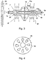
- FIG. 3 a valve arrangement is shown with a valve body 11 a, which encloses a valve control chamber 12 a, in which a closure body 17 is movably mounted.
- the closure body 17 has a magnetically active core 17a and a sheath 17b enclosing the core 17a, in particular made of a plastic, and is connected to a bearing disk 18.
- the bearing disc is in a view in the FIG. 4 shown. It is mounted on its circumference on the valve body 11a and overall elastic, so that it holds the closure body 17 in the illustrated center position.
- the bearing plate 18 has a plurality of openings 25, which allow the passage of the fluid to be controlled by the valve.
- FIG. 5 is shown in a three-dimensional view of the valve body 11a as a housing which encloses the valve control chamber 12a and the inflow channel 1 and the discharge channel 2, and the housing 16a containing the magnetic means A 'and B'.
- the housing 11a is, if a part of the valve device is to be used as a one-way valve, of the housing part 16a separable, so that the magnetic devices can be used repeatedly or further, while the part of the valve, which contains the valve control chamber 12a, can be replaced.
- FIG. 6 shows a solenoid valve with a transport channel, which is traversed by a fluid between an inflow opening 1 'and a drain opening 2'.
- a closure body 50 can be driven within the transport channel 88 between a first closure position and a second closure position, wherein in the first closure position, a first closure surface 51 closes a valve opening 51a, while in the second closure position, a closure surface 52 closes a valve opening 52a.
- the FIG. 8th 1 shows a catheter device 100 including a drive device with a rotatably drivable drive armature 66, which drives a rotating shaft 67 in a catheter 68.
- a catheter 68 Within the catheter 68, lumens, configured as an inflow channel 69 radially outward and a return flow channel 70 radially inward, are arranged concentrically with each other and with the outer sheath of the catheter.
- the inflow channel 69 and the return flow channel 70 are separated by a tubular partition 71.
- FIG. 9 shows a structure similar to that FIG. 8th , wherein in addition to the valve 75 in front of the drive armature 66 and behind the peristaltic pump 72, a second valve 75 'is disposed between the return flow passage 70 and the return flow pump 80.
- FIG.8 In flushing systems is used in which no unwanted negative pressure in the return is generated by system components, it is possible FIG.9 can also be used in flushing systems in which an unwanted negative pressure is created in the return line (eg due to the winding direction of a flexible shaft). This negative pressure is detected by the sensor, which then ensures by closing the valve 75 'down that no medium from container 82 via the pump 81 comes into the rinse cycle.
- the separating device is thus arranged between two valves and also between two fluid conveying devices, of which at least one, in particular both, with respect to the conveying direction of the fluid can be switched to reverse the flow direction.
- a peristaltic pump 72 with a reservoir 83 which allows gravity flushing by flowing the fluid through the valve 75 and on to the catheter 68 by gravity.
- the rotating shaft 84 within the catheter 68 has, due to its stranded stranded strand-based construction, a coiled outer structure which gives it a pumping action in the direction away from the drive armature 66 even upon rotation.
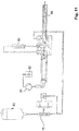
- FIG. 11 shows a constellation similar to that FIG. 9 , wherein instead of the peristaltic pump 72, a gravity feed 83 is provided, wherein the fluid in normal operation from there via the valve into the catheter 68 and there first through the inflow 69 radially outward into the return flow channel 70 radially inside and from there to a peristaltic pump 81, the aspirates the fluid and directs it into the reservoir 82.
- the fluid first passes through the separating device 80, which is arranged between the return flow channel and the housing of the drive armature 66. Thereafter, the fluid flows past the drive armature 66 to the peristaltic pump 81.
- FIG. 12 shows a structure similar to the FIG. 9 , wherein a further separating device 80 'ensures that the function of the sealing surfaces of the valve 75' is not impaired by adhering particles.
Landscapes
- Health & Medical Sciences (AREA)
- Heart & Thoracic Surgery (AREA)
- Engineering & Computer Science (AREA)
- Life Sciences & Earth Sciences (AREA)
- Public Health (AREA)
- Veterinary Medicine (AREA)
- Hematology (AREA)
- Anesthesiology (AREA)
- Animal Behavior & Ethology (AREA)
- General Health & Medical Sciences (AREA)
- Biomedical Technology (AREA)
- Cardiology (AREA)
- Mechanical Engineering (AREA)
- Pulmonology (AREA)
- Vascular Medicine (AREA)
- Medical Informatics (AREA)
- Biophysics (AREA)
- Infusion, Injection, And Reservoir Apparatuses (AREA)
- External Artificial Organs (AREA)
- Media Introduction/Drainage Providing Device (AREA)
- Transplantation (AREA)
Priority Applications (1)
| Application Number | Priority Date | Filing Date | Title |
|---|---|---|---|
| EP24169911.5A EP4434571A3 (fr) | 2015-01-22 | 2016-01-22 | Dispositif de cathéter comportant une soupape de commande d'un écoulement de fluide à travers un cathéter |
Applications Claiming Priority (4)
| Application Number | Priority Date | Filing Date | Title |
|---|---|---|---|
| EP15152205.9A EP3047911A1 (fr) | 2015-01-22 | 2015-01-22 | Dispositif de séparation destiné à retenir des particules magnétiques se trouvant dans un fluide et dispositif de protection pour un élément de fonction |
| EP15152201.8A EP3047873A1 (fr) | 2015-01-22 | 2015-01-22 | Soupape magnétique pour la commande d'un flux de fluide à travers un cathéter |
| PCT/EP2016/051358 WO2016116608A2 (fr) | 2015-01-22 | 2016-01-22 | Dispositif de cathéter, comprenant une soupape pour commander un flux de fluide à travers un cathéter |
| EP16701465.3A EP3247450B1 (fr) | 2015-01-22 | 2016-01-22 | Catheter avec soupape magnétique pour la commande d'un flux de fluide à travers le cathéter |
Related Parent Applications (2)
| Application Number | Title | Priority Date | Filing Date |
|---|---|---|---|
| EP16701465.3A Division EP3247450B1 (fr) | 2015-01-22 | 2016-01-22 | Catheter avec soupape magnétique pour la commande d'un flux de fluide à travers le cathéter |
| EP16701465.3A Division-Into EP3247450B1 (fr) | 2015-01-22 | 2016-01-22 | Catheter avec soupape magnétique pour la commande d'un flux de fluide à travers le cathéter |
Related Child Applications (2)
| Application Number | Title | Priority Date | Filing Date |
|---|---|---|---|
| EP24169911.5A Division EP4434571A3 (fr) | 2015-01-22 | 2016-01-22 | Dispositif de cathéter comportant une soupape de commande d'un écoulement de fluide à travers un cathéter |
| EP24169911.5A Division-Into EP4434571A3 (fr) | 2015-01-22 | 2016-01-22 | Dispositif de cathéter comportant une soupape de commande d'un écoulement de fluide à travers un cathéter |
Publications (2)
| Publication Number | Publication Date |
|---|---|
| EP3572120A1 true EP3572120A1 (fr) | 2019-11-27 |
| EP3572120B1 EP3572120B1 (fr) | 2024-05-22 |
Family
ID=55229682
Family Applications (5)
| Application Number | Title | Priority Date | Filing Date |
|---|---|---|---|
| EP24169911.5A Pending EP4434571A3 (fr) | 2015-01-22 | 2016-01-22 | Dispositif de cathéter comportant une soupape de commande d'un écoulement de fluide à travers un cathéter |
| EP16701474.5A Active EP3247500B1 (fr) | 2015-01-22 | 2016-01-22 | Dispositif de séparation destiné à retenir des particules magnétiques se trouvant dans un fluide et dispositif de protection pour un élément de fonction |
| EP19185354.8A Active EP3572120B1 (fr) | 2015-01-22 | 2016-01-22 | Dispositif de cathéter comportant une soupape de commande d'un écoulement de fluide à travers un cathéter |
| EP16701465.3A Active EP3247450B1 (fr) | 2015-01-22 | 2016-01-22 | Catheter avec soupape magnétique pour la commande d'un flux de fluide à travers le cathéter |
| EP25181307.7A Pending EP4588502A3 (fr) | 2015-01-22 | 2016-01-22 | Dispositif à cathéter comprenant un dispositif de séparation destiné à retenir des particules magnétiques contenues dans un fluide et dispositif de protection pour un élément fonctionnel |
Family Applications Before (2)
| Application Number | Title | Priority Date | Filing Date |
|---|---|---|---|
| EP24169911.5A Pending EP4434571A3 (fr) | 2015-01-22 | 2016-01-22 | Dispositif de cathéter comportant une soupape de commande d'un écoulement de fluide à travers un cathéter |
| EP16701474.5A Active EP3247500B1 (fr) | 2015-01-22 | 2016-01-22 | Dispositif de séparation destiné à retenir des particules magnétiques se trouvant dans un fluide et dispositif de protection pour un élément de fonction |
Family Applications After (2)
| Application Number | Title | Priority Date | Filing Date |
|---|---|---|---|
| EP16701465.3A Active EP3247450B1 (fr) | 2015-01-22 | 2016-01-22 | Catheter avec soupape magnétique pour la commande d'un flux de fluide à travers le cathéter |
| EP25181307.7A Pending EP4588502A3 (fr) | 2015-01-22 | 2016-01-22 | Dispositif à cathéter comprenant un dispositif de séparation destiné à retenir des particules magnétiques contenues dans un fluide et dispositif de protection pour un élément fonctionnel |
Country Status (9)
| Country | Link |
|---|---|
| US (5) | US10518010B2 (fr) |
| EP (5) | EP4434571A3 (fr) |
| JP (10) | JP6716579B2 (fr) |
| KR (7) | KR20250159266A (fr) |
| CN (9) | CN107206225B (fr) |
| CA (2) | CA2973892A1 (fr) |
| DK (3) | DK3247500T3 (fr) |
| ES (3) | ES2758077T3 (fr) |
| WO (2) | WO2016116608A2 (fr) |
Families Citing this family (32)
| Publication number | Priority date | Publication date | Assignee | Title |
|---|---|---|---|---|
| AU2007230945B2 (en) | 2006-03-23 | 2013-05-02 | The Penn State Research Foundation | Heart assist device with expandable impeller pump |
| GB2504176A (en) | 2012-05-14 | 2014-01-22 | Thoratec Corp | Collapsible impeller for catheter pump |
| GB2504177B (en) | 2012-05-14 | 2014-12-10 | Thoratec Corp | Sheath system for catheter pump |
| US9446179B2 (en) | 2012-05-14 | 2016-09-20 | Thoratec Corporation | Distal bearing support |
| US9358329B2 (en) | 2012-07-03 | 2016-06-07 | Thoratec Corporation | Catheter pump |
| WO2014164136A1 (fr) | 2013-03-13 | 2014-10-09 | Thoratec Corporation | Système de traitement de fluide |
| US10363349B2 (en) | 2014-04-15 | 2019-07-30 | Tc1 Llp | Heart pump providing adjustable outflow |
| US10583232B2 (en) | 2014-04-15 | 2020-03-10 | Tc1 Llc | Catheter pump with off-set motor position |
| EP3808401A1 (fr) * | 2016-07-21 | 2021-04-21 | Tc1 Llc | Chambre remplie de gaz pour ensemble moteur de pompe de cathéter |
| EP3808403A1 (fr) | 2016-07-21 | 2021-04-21 | Tc1 Llc | Joints fluidiques pour ensemble moteur de pompe à cathéter |
| EP3525872B1 (fr) * | 2016-10-17 | 2020-09-02 | Bayer Healthcare LLC | Soupape de régulation de fluide et collecteur |
| EP4299085A3 (fr) | 2016-12-19 | 2024-01-31 | Abiomed, Inc. | Pompe cardiaque avec système de purge passif |
| EP4732889A2 (fr) | 2017-06-07 | 2026-04-29 | Supira Medical, Inc. | Dispositifs de déplacement de fluide intravasculaire, systèmes et procédés d'utilisation |
| US11511103B2 (en) | 2017-11-13 | 2022-11-29 | Shifamed Holdings, Llc | Intravascular fluid movement devices, systems, and methods of use |
| JP7410034B2 (ja) | 2018-02-01 | 2024-01-09 | シファメド・ホールディングス・エルエルシー | 血管内血液ポンプならびに使用および製造の方法 |
| WO2020028537A1 (fr) | 2018-07-31 | 2020-02-06 | Shifamed Holdings, Llc | Pompes sanguines intravasculaires et procédés d'utilisation |
| WO2020073047A1 (fr) | 2018-10-05 | 2020-04-09 | Shifamed Holdings, Llc | Pompes à sang intravasculaires et procédés d'utilisation |
| WO2021011473A1 (fr) | 2019-07-12 | 2021-01-21 | Shifamed Holdings, Llc | Pompes à sang intravasculaires et méthode d'utilisation et procédé de fabrication |
| US11654275B2 (en) | 2019-07-22 | 2023-05-23 | Shifamed Holdings, Llc | Intravascular blood pumps with struts and methods of use and manufacture |
| EP4010046A4 (fr) | 2019-08-07 | 2023-08-30 | Calomeni, Michael | Pompes sanguines à cathéter et boîtiers de pompe pliants |
| EP4034192B1 (fr) | 2019-09-25 | 2025-12-24 | Supira Medical, Inc. | Dispositifs et systèmes de pompes à sang intravasculaires et leurs procédés d'utilisation et de commande |
| WO2021062260A1 (fr) | 2019-09-25 | 2021-04-01 | Shifamed Holdings, Llc | Pompes à sang de cathéter et conduits sanguins pliables |
| EP4034221B1 (fr) | 2019-09-25 | 2024-11-13 | Shifamed Holdings, LLC | Pompes à sang de cathéter et boîtiers de pompe pliables |
| CN110604850B (zh) * | 2019-10-28 | 2024-08-27 | 广东安特医疗有限公司 | 三通阀和输液装置 |
| EP4072650A4 (fr) | 2019-12-11 | 2024-01-10 | Shifamed Holdings, LLC | Pompes à sang d'aorte descendante et de veine cave |
| US12599758B2 (en) | 2019-12-19 | 2026-04-14 | Shifamed Holdings, Llc | Intravascular blood pumps, motors, and fluid control |
| CN111821528A (zh) * | 2020-06-16 | 2020-10-27 | 北京工业大学 | 功能性人工左心室系统 |
| CN112791305A (zh) * | 2021-01-22 | 2021-05-14 | 苏州心擎医疗技术有限公司 | 血泵及其动力传递组件 |
| DE102021001563B4 (de) | 2021-03-25 | 2022-12-22 | Uromed Kurt Drews Kg | Katheterventil zum Steuern des Fluidflusses eines Mediums |
| WO2023283751A1 (fr) * | 2021-07-12 | 2023-01-19 | 苏州心擎医疗技术有限公司 | Dispositif d'assistance cardiaque en cas d'insuffisance cardiaque |
| WO2023284339A1 (fr) * | 2021-07-12 | 2023-01-19 | 苏州心擎医疗技术有限公司 | Dispositif d'assistance cardiaque en cas d'insuffisance fonctionnelle cardiaque |
| CN113926074B (zh) * | 2021-11-04 | 2023-10-31 | 丰凯利医疗器械(上海)有限公司 | 导流传动装置以及血泵系统 |
Citations (9)
| Publication number | Priority date | Publication date | Assignee | Title |
|---|---|---|---|---|
| US3570807A (en) * | 1969-01-14 | 1971-03-16 | Bell Aerospace Corp | Electromechanical control valve |
| DE4123091A1 (de) * | 1991-07-12 | 1993-01-14 | Anschuetz & Co Gmbh | Ventil, insbesondere fuer infusionspumpen |
| US20040055652A1 (en) * | 2002-09-20 | 2004-03-25 | John Erickson | Dosage control apparatus |
| WO2008101352A1 (fr) * | 2007-02-22 | 2008-08-28 | Simonson Roger M | Filtre magnétique et ensemble de filtrage magnétique |
| EP2246078A1 (fr) * | 2009-04-29 | 2010-11-03 | ECP Entwicklungsgesellschaft mbH | Agencement d'arbres doté d'un arbre se déroulant à l'intérieur d'une enveloppe rempli de fluide |
| US20100331753A1 (en) * | 2008-02-02 | 2010-12-30 | Alberto Gandini | A Blood Purification Method and Apparatus for the Treatment of Malaria |
| DE112009003676T5 (de) | 2008-12-02 | 2012-10-18 | Piolax Inc. | Ruckschlagventil |
| DE202013104711U1 (de) | 2013-10-18 | 2013-11-06 | Fang Zhengda | Ein Einwegventil |
| US20140261717A1 (en) * | 2013-03-15 | 2014-09-18 | Fresenius Medical Care Holdings, Inc. | Dialysis control valve having self-cleaning mode |
Family Cites Families (60)
| Publication number | Priority date | Publication date | Assignee | Title |
|---|---|---|---|---|
| GB768451A (en) * | 1954-03-22 | 1957-02-20 | Jones George Henry | Method of and means for magnetically separating solid magnetic particles from a fluid current |
| US3642004A (en) * | 1970-01-05 | 1972-02-15 | Life Support Equipment Corp | Urethral valve |
| CH591178A5 (fr) * | 1972-11-03 | 1977-09-15 | Anvar | |
| US4078998A (en) * | 1974-10-21 | 1978-03-14 | Robin Roy Oder | Magnetic separator |
| US4038982A (en) * | 1975-12-03 | 1977-08-02 | Burron Medical Products, Inc. | Electrically controlled intravenous infusion set |
| US4357237A (en) | 1979-11-28 | 1982-11-02 | Sanderson Charles H | Device for the magnetic treatment of water and liquid and gaseous fuels |
| CA1124153A (fr) * | 1979-12-14 | 1982-05-25 | James E. Young | Dispositif de regulation du debit pour catheter arteriel |
| US4375407A (en) * | 1981-06-22 | 1983-03-01 | The Franklin Institute | High gradient magnetic separation device |
| MC1604A1 (fr) * | 1984-03-07 | 1985-05-09 | Eaton Corp | Vanne a commande electro-magnetique |
| US4596558A (en) * | 1985-09-13 | 1986-06-24 | Queen's University At Kingston | Pulsed external medication dispenser |
| US4895557A (en) * | 1987-12-07 | 1990-01-23 | Nimbus Medical, Inc. | Drive mechanism for powering intravascular blood pumps |
| JPH069669Y2 (ja) * | 1989-03-03 | 1994-03-16 | 株式会社三陽電機製作所 | 血液透析装置 |
| DE4224389B4 (de) * | 1992-07-23 | 2004-02-19 | AVS, Ing. J.C. Römer GmbH | Ventil mit T-förmigem bzw. N-förmigem, wippenartigem Ventilglied |
| US5655665A (en) * | 1994-12-09 | 1997-08-12 | Georgia Tech Research Corporation | Fully integrated micromachined magnetic particle manipulator and separator |
| JPH0957149A (ja) * | 1995-08-28 | 1997-03-04 | Furukawa Electric Co Ltd:The | 磁性粉除去装置 |
| NL1003056C2 (nl) * | 1996-05-07 | 1997-11-10 | Cordis Europ | Zuigkatheter met hemostase-inrichting. |
| DE19717790A1 (de) * | 1997-04-26 | 1998-10-29 | Convergenza Ag | Vorrichtung mit einem therapeutischen Katheter |
| CN1105850C (zh) | 1998-06-29 | 2003-04-16 | 斯冈株式会社 | 流路切换装置 |
| US6245007B1 (en) * | 1999-01-28 | 2001-06-12 | Terumo Cardiovascular Systems Corporation | Blood pump |
| WO2001017581A2 (fr) | 1999-09-03 | 2001-03-15 | A-Med Systems, Inc. | Pompe a sang intravasculaire pouvant etre guidee et procedes s"y rapportant |
| US7655016B2 (en) * | 1999-09-17 | 2010-02-02 | Covidien | Mechanical pump for removal of fragmented matter and methods of manufacture and use |
| IT1316850B1 (it) * | 2000-03-24 | 2003-05-12 | Curzio Aldo Magri | Dispositivo per l'erogazione di fluidi alimentari,particolarmente perdistributori automatici o semiautomatici di bevande calde o fredde |
| US6673051B2 (en) * | 2001-04-02 | 2004-01-06 | Hook Research Foundation | Magnetic valve bladder cycler drainage system and use method with urinary catheters |
| US20030120202A1 (en) * | 2001-12-21 | 2003-06-26 | Gordon Lucas S. | Magnetic extracorporeal circuit for removal of medical agents |
| DE20302911U1 (de) * | 2003-02-22 | 2004-07-01 | Hengst Gmbh & Co.Kg | Ventil für die Kurbelgehäuseentlüftung einer Verbrennungsmaschine |
| DE502004007022D1 (de) * | 2003-03-06 | 2008-06-19 | Roemer J C Avs Gmbh | Pneumatisch betätigtes Ventil |
| EP1750598B1 (fr) * | 2004-03-19 | 2013-11-20 | Medical Components, Inc. | Manchette magnetique pour tubes et catheters vasculaires |
| DE102004034480A1 (de) * | 2004-07-15 | 2006-02-09 | Microcuff Gmbh | Ventil zur Fülldruckregelung bei Niedrigdruck-Ballonkathetern |
| US20060276744A1 (en) * | 2005-05-20 | 2006-12-07 | Falk Theodore J | Configuration for drug delivery systems |
| US7604748B2 (en) * | 2005-10-20 | 2009-10-20 | Eclipse Magnetics Limited | Magnetic filter |
| US8127791B2 (en) * | 2005-12-21 | 2012-03-06 | Saturn Electronics & Engineering, Inc. | Solenoid operated fluid control valve |
| AU2007266459B2 (en) | 2006-05-31 | 2013-01-17 | Star Bp, Inc. | Heart assist device |
| DE502007005015C5 (de) | 2007-10-08 | 2020-02-20 | Ais Gmbh Aachen Innovative Solutions | Katheter-Vorrichtung |
| ES2660180T3 (es) | 2007-12-07 | 2018-03-21 | Miltenyi Biotec Gmbh | Sistemas y métodos para procesamiento de células |
| CA2716657A1 (fr) | 2008-03-05 | 2009-09-11 | Robert Hoch | Catheter capteur de pression |
| US8491541B2 (en) * | 2008-09-30 | 2013-07-23 | Covidien Lp | Ball-valve actuation mechanism |
| US8256739B2 (en) * | 2008-12-22 | 2012-09-04 | Husco International, Inc. | Poppet valve operated by an electrohydraulic poppet pilot valve |
| JP2010151738A (ja) * | 2008-12-26 | 2010-07-08 | Tosoh Corp | 磁性粒子の分離方法および装置 |
| JP5745400B2 (ja) * | 2009-04-20 | 2015-07-08 | 株式会社ケイロン・ジャパン | 排尿制御装置 |
| EP2248544A1 (fr) * | 2009-05-05 | 2010-11-10 | ECP Entwicklungsgesellschaft mbH | Pompe à fluide à diamètre modifiable, notamment à des fins médicales |
| KR101659640B1 (ko) * | 2009-06-22 | 2016-09-26 | 엔피 메디컬 인크. | 개선된 역압 밀봉을 갖는 의료용 밸브 |
| AU2011224640B2 (en) * | 2010-03-06 | 2015-05-07 | Nfusion Vascular Systems, Llc | Recovery catheter assembly |
| EP2368639A1 (fr) * | 2010-03-23 | 2011-09-28 | Siemens Aktiengesellschaft | Dispositif et procédé de séparation magnétique d'un liquide |
| DE102010023131A1 (de) * | 2010-06-09 | 2011-12-15 | Basf Se | Anordnung und Verfahren zum Trennen magnetisierbarer Partikel von einer Flüssigkeit |
| EP2422735A1 (fr) | 2010-08-27 | 2012-02-29 | ECP Entwicklungsgesellschaft mbH | Dispositif de transport de sang implantable, dispositif de manipulation et dispositif de couplage |
| US20120145641A1 (en) * | 2010-08-31 | 2012-06-14 | Justin Rebo | Method and Apparatus for removing senescent cells |
| DE102010042723A1 (de) * | 2010-10-20 | 2012-04-26 | Miltenyi Biotec Gmbh | Vorrichtung und Verfahren zur Separation von Neél- und Brown-magnetischen Partikeln |
| WO2012094535A2 (fr) * | 2011-01-06 | 2012-07-12 | Thoratec Corporation | Pompe cardiaque percutanée |
| DE102011003825A1 (de) * | 2011-02-09 | 2012-08-09 | Siemens Aktiengesellschaft | Vorrichtung zur Abscheidung ferromagnetischer Partikel aus einer Suspension |
| CA2829405A1 (fr) * | 2011-03-11 | 2012-09-20 | Guisheng Yang | Dispositif et procede de piegeage de particules magnetiques |
| EP2720728A4 (fr) * | 2011-06-14 | 2014-12-10 | Hangzhou Everlong Biotechnics Co Ltd | Système dirigé sur cible, à fonctionnalité magnétique pour la détoxification de patients |
| JP3178785U (ja) * | 2011-12-27 | 2012-10-04 | ファハド,アルカンハル | 携帯用血液透析装置 |
| PL2834009T3 (pl) * | 2012-04-03 | 2018-05-30 | Spiro Enterprises B.V. | Układ obiegu płynu dla obiegowej ilości płynu zawierający magnetyczny separator do oddzielania zawieszonych cząstek mających ferromagnetyczne właściwości i odpowiedni sposób |
| US20130334120A1 (en) * | 2012-06-15 | 2013-12-19 | President And Fellows Of Harvard College | Fluid cleansing devices and methods of use |
| US20140107589A1 (en) * | 2012-10-17 | 2014-04-17 | Farid Amirouche | Electromagnetically actuated valve and related methods of use |
| US9242077B2 (en) * | 2013-03-12 | 2016-01-26 | DePuy Synthes Products, Inc. | Dynamic adjustment tool for programming an implantable valve |
| WO2014164136A1 (fr) * | 2013-03-13 | 2014-10-09 | Thoratec Corporation | Système de traitement de fluide |
| US9719738B2 (en) * | 2013-03-14 | 2017-08-01 | Hydroflux Technology, Llc | Apparatus and method for applying magnetic fields to fluid flows |
| US10286196B2 (en) * | 2016-06-30 | 2019-05-14 | Integra Lifesciences Switzerland Sàrl | Device to control magnetic rotor of a programmable hydrocephalus valve |
| GB2578651B (en) * | 2018-10-31 | 2022-09-14 | Ingenion Medical Ltd | An intraurethral magnetic valve and associated parts |
-
2016
- 2016-01-22 KR KR1020257035144A patent/KR20250159266A/ko active Pending
- 2016-01-22 WO PCT/EP2016/051358 patent/WO2016116608A2/fr not_active Ceased
- 2016-01-22 DK DK16701474.5T patent/DK3247500T3/da active
- 2016-01-22 CN CN201680006875.XA patent/CN107206225B/zh active Active
- 2016-01-22 CN CN202110513424.8A patent/CN113181548B/zh active Active
- 2016-01-22 CN CN202310814930.XA patent/CN116808431A/zh active Pending
- 2016-01-22 CA CA2973892A patent/CA2973892A1/fr active Pending
- 2016-01-22 KR KR1020177022700A patent/KR102547508B1/ko active Active
- 2016-01-22 CN CN202011429973.9A patent/CN112569451B/zh active Active
- 2016-01-22 CA CA2974584A patent/CA2974584A1/fr active Pending
- 2016-01-22 JP JP2017538967A patent/JP6716579B2/ja active Active
- 2016-01-22 KR KR1020237008679A patent/KR102723289B1/ko active Active
- 2016-01-22 EP EP24169911.5A patent/EP4434571A3/fr active Pending
- 2016-01-22 KR KR1020177022929A patent/KR102510791B1/ko active Active
- 2016-01-22 EP EP16701474.5A patent/EP3247500B1/fr active Active
- 2016-01-22 US US15/545,003 patent/US10518010B2/en active Active
- 2016-01-22 KR KR1020237020826A patent/KR102876100B1/ko active Active
- 2016-01-22 CN CN202010855035.9A patent/CN111905230B/zh active Active
- 2016-01-22 ES ES16701465T patent/ES2758077T3/es active Active
- 2016-01-22 EP EP19185354.8A patent/EP3572120B1/fr active Active
- 2016-01-22 DK DK16701465T patent/DK3247450T3/da active
- 2016-01-22 KR KR1020247035499A patent/KR102900636B1/ko active Active
- 2016-01-22 CN CN202411552638.6A patent/CN119185774A/zh active Pending
- 2016-01-22 CN CN201680006882.XA patent/CN107206136B/zh active Active
- 2016-01-22 CN CN202310263436.9A patent/CN116271417A/zh active Pending
- 2016-01-22 CN CN202010855332.3A patent/CN111905231B/zh active Active
- 2016-01-22 EP EP16701465.3A patent/EP3247450B1/fr active Active
- 2016-01-22 WO PCT/EP2016/051391 patent/WO2016116630A2/fr not_active Ceased
- 2016-01-22 EP EP25181307.7A patent/EP4588502A3/fr active Pending
- 2016-01-22 JP JP2017538959A patent/JP6599997B2/ja active Active
- 2016-01-22 KR KR1020257041472A patent/KR20260003385A/ko active Pending
- 2016-01-22 ES ES16701474T patent/ES3041172T3/es active Active
- 2016-01-22 US US15/545,037 patent/US10960117B2/en active Active
- 2016-01-22 DK DK19185354.8T patent/DK3572120T3/da active
- 2016-01-22 ES ES19185354T patent/ES2985131T3/es active Active
-
2019
- 2019-10-03 JP JP2019182662A patent/JP6905023B2/ja active Active
- 2019-11-25 US US16/694,518 patent/US11045641B2/en active Active
-
2020
- 2020-06-10 JP JP2020100567A patent/JP6938725B2/ja active Active
-
2021
- 2021-02-12 US US17/174,455 patent/US12472342B2/en active Active
- 2021-05-17 US US17/322,374 patent/US20210339010A1/en active Pending
- 2021-06-24 JP JP2021104512A patent/JP2021180845A/ja active Pending
- 2021-09-01 JP JP2021142284A patent/JP7481307B2/ja active Active
-
2022
- 2022-08-08 JP JP2022126515A patent/JP7453290B2/ja active Active
-
2023
- 2023-12-26 JP JP2023219040A patent/JP7847402B2/ja active Active
-
2024
- 2024-03-07 JP JP2024034531A patent/JP7719226B2/ja active Active
-
2025
- 2025-07-24 JP JP2025123699A patent/JP2025137754A/ja active Pending
Patent Citations (9)
| Publication number | Priority date | Publication date | Assignee | Title |
|---|---|---|---|---|
| US3570807A (en) * | 1969-01-14 | 1971-03-16 | Bell Aerospace Corp | Electromechanical control valve |
| DE4123091A1 (de) * | 1991-07-12 | 1993-01-14 | Anschuetz & Co Gmbh | Ventil, insbesondere fuer infusionspumpen |
| US20040055652A1 (en) * | 2002-09-20 | 2004-03-25 | John Erickson | Dosage control apparatus |
| WO2008101352A1 (fr) * | 2007-02-22 | 2008-08-28 | Simonson Roger M | Filtre magnétique et ensemble de filtrage magnétique |
| US20100331753A1 (en) * | 2008-02-02 | 2010-12-30 | Alberto Gandini | A Blood Purification Method and Apparatus for the Treatment of Malaria |
| DE112009003676T5 (de) | 2008-12-02 | 2012-10-18 | Piolax Inc. | Ruckschlagventil |
| EP2246078A1 (fr) * | 2009-04-29 | 2010-11-03 | ECP Entwicklungsgesellschaft mbH | Agencement d'arbres doté d'un arbre se déroulant à l'intérieur d'une enveloppe rempli de fluide |
| US20140261717A1 (en) * | 2013-03-15 | 2014-09-18 | Fresenius Medical Care Holdings, Inc. | Dialysis control valve having self-cleaning mode |
| DE202013104711U1 (de) | 2013-10-18 | 2013-11-06 | Fang Zhengda | Ein Einwegventil |
Also Published As
Similar Documents
| Publication | Publication Date | Title |
|---|---|---|
| EP3247450B1 (fr) | Catheter avec soupape magnétique pour la commande d'un flux de fluide à travers le cathéter | |
| EP3047873A1 (fr) | Soupape magnétique pour la commande d'un flux de fluide à travers un cathéter | |
| EP3047911A1 (fr) | Dispositif de séparation destiné à retenir des particules magnétiques se trouvant dans un fluide et dispositif de protection pour un élément de fonction | |
| EP2490753B1 (fr) | Robinet à plusieurs voies présentant des surfaces à action antiseptique ou antimicrobienne | |
| WO2017216237A1 (fr) | Interface d'alimentation en fluide équipée d'un dispositif de lavage à contre-courant, utilisation d'une telle interface d'alimentation en fluide | |
| DE102014005137A1 (de) | Elektromagnetisch betätigtes Ventil | |
| DE202010000078U1 (de) | Fluiddurchströmte Verbindungssysteme zum Einsatz in der Medizin und Medizintechnik | |
| DE102010038872A1 (de) | Pumpe | |
| EP3070383B1 (fr) | Servo-soupape | |
| EP4151186B1 (fr) | Cartouche pour console de système de chirurgie ophtalmologique et système de chirurgie ophtalmologique | |
| HK40110897A (en) | Catheter device, comprising a valve for controlling a flow of a fluid through a catheter | |
| DE102016216640A1 (de) | Hahnarmatur | |
| HK1243009A1 (en) | Catheter device, comprising a valve for controlling a fluid flow through a catheter |
Legal Events
| Date | Code | Title | Description |
|---|---|---|---|
| PUAI | Public reference made under article 153(3) epc to a published international application that has entered the european phase |
Free format text: ORIGINAL CODE: 0009012 |
|
| STAA | Information on the status of an ep patent application or granted ep patent |
Free format text: STATUS: THE APPLICATION HAS BEEN PUBLISHED |
|
| AC | Divisional application: reference to earlier application |
Ref document number: 3247450 Country of ref document: EP Kind code of ref document: P |
|
| AK | Designated contracting states |
Kind code of ref document: A1 Designated state(s): AL AT BE BG CH CY CZ DE DK EE ES FI FR GB GR HR HU IE IS IT LI LT LU LV MC MK MT NL NO PL PT RO RS SE SI SK SM TR |
|
| STAA | Information on the status of an ep patent application or granted ep patent |
Free format text: STATUS: REQUEST FOR EXAMINATION WAS MADE |
|
| 17P | Request for examination filed |
Effective date: 20200324 |
|
| RBV | Designated contracting states (corrected) |
Designated state(s): AL AT BE BG CH CY CZ DE DK EE ES FI FR GB GR HR HU IE IS IT LI LT LU LV MC MK MT NL NO PL PT RO RS SE SI SK SM TR |
|
| REG | Reference to a national code |
Ref country code: HK Ref legal event code: DE Ref document number: 40012181 Country of ref document: HK |
|
| STAA | Information on the status of an ep patent application or granted ep patent |
Free format text: STATUS: EXAMINATION IS IN PROGRESS |
|
| 17Q | First examination report despatched |
Effective date: 20210303 |
|
| GRAP | Despatch of communication of intention to grant a patent |
Free format text: ORIGINAL CODE: EPIDOSNIGR1 |
|
| STAA | Information on the status of an ep patent application or granted ep patent |
Free format text: STATUS: GRANT OF PATENT IS INTENDED |
|
| RIC1 | Information provided on ipc code assigned before grant |
Ipc: A61M 60/148 20210101ALI20230620BHEP Ipc: A61M 60/13 20210101ALI20230620BHEP Ipc: F16K 31/06 20060101ALI20230620BHEP Ipc: A61M 60/279 20210101ALI20230620BHEP Ipc: B03C 1/28 20060101ALI20230620BHEP Ipc: A61M 60/438 20210101ALI20230620BHEP Ipc: A61M 60/523 20210101ALI20230620BHEP Ipc: A61M 60/546 20210101ALI20230620BHEP Ipc: A61M 39/22 20060101AFI20230620BHEP |
|
| INTG | Intention to grant announced |
Effective date: 20230719 |
|
| GRAJ | Information related to disapproval of communication of intention to grant by the applicant or resumption of examination proceedings by the epo deleted |
Free format text: ORIGINAL CODE: EPIDOSDIGR1 |
|
| STAA | Information on the status of an ep patent application or granted ep patent |
Free format text: STATUS: EXAMINATION IS IN PROGRESS |
|
| GRAP | Despatch of communication of intention to grant a patent |
Free format text: ORIGINAL CODE: EPIDOSNIGR1 |
|
| STAA | Information on the status of an ep patent application or granted ep patent |
Free format text: STATUS: GRANT OF PATENT IS INTENDED |
|
| INTC | Intention to grant announced (deleted) | ||
| INTG | Intention to grant announced |
Effective date: 20231212 |
|
| GRAS | Grant fee paid |
Free format text: ORIGINAL CODE: EPIDOSNIGR3 |
|
| GRAA | (expected) grant |
Free format text: ORIGINAL CODE: 0009210 |
|
| STAA | Information on the status of an ep patent application or granted ep patent |
Free format text: STATUS: THE PATENT HAS BEEN GRANTED |
|
| AC | Divisional application: reference to earlier application |
Ref document number: 3247450 Country of ref document: EP Kind code of ref document: P |
|
| AK | Designated contracting states |
Kind code of ref document: B1 Designated state(s): AL AT BE BG CH CY CZ DE DK EE ES FI FR GB GR HR HU IE IS IT LI LT LU LV MC MK MT NL NO PL PT RO RS SE SI SK SM TR |
|
| P01 | Opt-out of the competence of the unified patent court (upc) registered |
Effective date: 20240412 |
|
| REG | Reference to a national code |
Ref country code: GB Ref legal event code: FG4D Free format text: NOT ENGLISH |
|
| REG | Reference to a national code |
Ref country code: CH Ref legal event code: EP |
|
| REG | Reference to a national code |
Ref country code: DE Ref legal event code: R096 Ref document number: 502016016559 Country of ref document: DE |
|
| REG | Reference to a national code |
Ref country code: IE Ref legal event code: FG4D Free format text: LANGUAGE OF EP DOCUMENT: GERMAN |
|
| REG | Reference to a national code |
Ref country code: DK Ref legal event code: T3 Effective date: 20240717 |
|
| REG | Reference to a national code |
Ref country code: SE Ref legal event code: TRGR |
|
| REG | Reference to a national code |
Ref country code: NL Ref legal event code: FP |
|
| REG | Reference to a national code |
Ref country code: LT Ref legal event code: MG9D |
|
| PG25 | Lapsed in a contracting state [announced via postgrant information from national office to epo] |
Ref country code: IS Free format text: LAPSE BECAUSE OF FAILURE TO SUBMIT A TRANSLATION OF THE DESCRIPTION OR TO PAY THE FEE WITHIN THE PRESCRIBED TIME-LIMIT Effective date: 20240922 |
|
| PG25 | Lapsed in a contracting state [announced via postgrant information from national office to epo] |
Ref country code: BG Free format text: LAPSE BECAUSE OF FAILURE TO SUBMIT A TRANSLATION OF THE DESCRIPTION OR TO PAY THE FEE WITHIN THE PRESCRIBED TIME-LIMIT Effective date: 20240522 |
|
| PG25 | Lapsed in a contracting state [announced via postgrant information from national office to epo] |
Ref country code: HR Free format text: LAPSE BECAUSE OF FAILURE TO SUBMIT A TRANSLATION OF THE DESCRIPTION OR TO PAY THE FEE WITHIN THE PRESCRIBED TIME-LIMIT Effective date: 20240522 Ref country code: FI Free format text: LAPSE BECAUSE OF FAILURE TO SUBMIT A TRANSLATION OF THE DESCRIPTION OR TO PAY THE FEE WITHIN THE PRESCRIBED TIME-LIMIT Effective date: 20240522 |
|
| PG25 | Lapsed in a contracting state [announced via postgrant information from national office to epo] |
Ref country code: GR Free format text: LAPSE BECAUSE OF FAILURE TO SUBMIT A TRANSLATION OF THE DESCRIPTION OR TO PAY THE FEE WITHIN THE PRESCRIBED TIME-LIMIT Effective date: 20240823 |
|
| PG25 | Lapsed in a contracting state [announced via postgrant information from national office to epo] |
Ref country code: PT Free format text: LAPSE BECAUSE OF FAILURE TO SUBMIT A TRANSLATION OF THE DESCRIPTION OR TO PAY THE FEE WITHIN THE PRESCRIBED TIME-LIMIT Effective date: 20240923 |
|
| PG25 | Lapsed in a contracting state [announced via postgrant information from national office to epo] |
Ref country code: PL Free format text: LAPSE BECAUSE OF FAILURE TO SUBMIT A TRANSLATION OF THE DESCRIPTION OR TO PAY THE FEE WITHIN THE PRESCRIBED TIME-LIMIT Effective date: 20240522 |
|
| PG25 | Lapsed in a contracting state [announced via postgrant information from national office to epo] |
Ref country code: LV Free format text: LAPSE BECAUSE OF FAILURE TO SUBMIT A TRANSLATION OF THE DESCRIPTION OR TO PAY THE FEE WITHIN THE PRESCRIBED TIME-LIMIT Effective date: 20240522 |
|
| PG25 | Lapsed in a contracting state [announced via postgrant information from national office to epo] |
Ref country code: PT Free format text: LAPSE BECAUSE OF FAILURE TO SUBMIT A TRANSLATION OF THE DESCRIPTION OR TO PAY THE FEE WITHIN THE PRESCRIBED TIME-LIMIT Effective date: 20240923 Ref country code: PL Free format text: LAPSE BECAUSE OF FAILURE TO SUBMIT A TRANSLATION OF THE DESCRIPTION OR TO PAY THE FEE WITHIN THE PRESCRIBED TIME-LIMIT Effective date: 20240522 Ref country code: NO Free format text: LAPSE BECAUSE OF FAILURE TO SUBMIT A TRANSLATION OF THE DESCRIPTION OR TO PAY THE FEE WITHIN THE PRESCRIBED TIME-LIMIT Effective date: 20240822 Ref country code: LV Free format text: LAPSE BECAUSE OF FAILURE TO SUBMIT A TRANSLATION OF THE DESCRIPTION OR TO PAY THE FEE WITHIN THE PRESCRIBED TIME-LIMIT Effective date: 20240522 Ref country code: IS Free format text: LAPSE BECAUSE OF FAILURE TO SUBMIT A TRANSLATION OF THE DESCRIPTION OR TO PAY THE FEE WITHIN THE PRESCRIBED TIME-LIMIT Effective date: 20240922 Ref country code: HR Free format text: LAPSE BECAUSE OF FAILURE TO SUBMIT A TRANSLATION OF THE DESCRIPTION OR TO PAY THE FEE WITHIN THE PRESCRIBED TIME-LIMIT Effective date: 20240522 Ref country code: GR Free format text: LAPSE BECAUSE OF FAILURE TO SUBMIT A TRANSLATION OF THE DESCRIPTION OR TO PAY THE FEE WITHIN THE PRESCRIBED TIME-LIMIT Effective date: 20240823 Ref country code: FI Free format text: LAPSE BECAUSE OF FAILURE TO SUBMIT A TRANSLATION OF THE DESCRIPTION OR TO PAY THE FEE WITHIN THE PRESCRIBED TIME-LIMIT Effective date: 20240522 Ref country code: BG Free format text: LAPSE BECAUSE OF FAILURE TO SUBMIT A TRANSLATION OF THE DESCRIPTION OR TO PAY THE FEE WITHIN THE PRESCRIBED TIME-LIMIT Effective date: 20240522 Ref country code: RS Free format text: LAPSE BECAUSE OF FAILURE TO SUBMIT A TRANSLATION OF THE DESCRIPTION OR TO PAY THE FEE WITHIN THE PRESCRIBED TIME-LIMIT Effective date: 20240822 |
|
| REG | Reference to a national code |
Ref country code: ES Ref legal event code: FG2A Ref document number: 2985131 Country of ref document: ES Kind code of ref document: T3 Effective date: 20241104 |
|
| PG25 | Lapsed in a contracting state [announced via postgrant information from national office to epo] |
Ref country code: EE Free format text: LAPSE BECAUSE OF FAILURE TO SUBMIT A TRANSLATION OF THE DESCRIPTION OR TO PAY THE FEE WITHIN THE PRESCRIBED TIME-LIMIT Effective date: 20240522 |
|
| PG25 | Lapsed in a contracting state [announced via postgrant information from national office to epo] |
Ref country code: CZ Free format text: LAPSE BECAUSE OF FAILURE TO SUBMIT A TRANSLATION OF THE DESCRIPTION OR TO PAY THE FEE WITHIN THE PRESCRIBED TIME-LIMIT Effective date: 20240522 |
|
| PG25 | Lapsed in a contracting state [announced via postgrant information from national office to epo] |
Ref country code: SK Free format text: LAPSE BECAUSE OF FAILURE TO SUBMIT A TRANSLATION OF THE DESCRIPTION OR TO PAY THE FEE WITHIN THE PRESCRIBED TIME-LIMIT Effective date: 20240522 Ref country code: RO Free format text: LAPSE BECAUSE OF FAILURE TO SUBMIT A TRANSLATION OF THE DESCRIPTION OR TO PAY THE FEE WITHIN THE PRESCRIBED TIME-LIMIT Effective date: 20240522 |
|
| PG25 | Lapsed in a contracting state [announced via postgrant information from national office to epo] |
Ref country code: SM Free format text: LAPSE BECAUSE OF FAILURE TO SUBMIT A TRANSLATION OF THE DESCRIPTION OR TO PAY THE FEE WITHIN THE PRESCRIBED TIME-LIMIT Effective date: 20240522 |
|
| PG25 | Lapsed in a contracting state [announced via postgrant information from national office to epo] |
Ref country code: SM Free format text: LAPSE BECAUSE OF FAILURE TO SUBMIT A TRANSLATION OF THE DESCRIPTION OR TO PAY THE FEE WITHIN THE PRESCRIBED TIME-LIMIT Effective date: 20240522 Ref country code: SK Free format text: LAPSE BECAUSE OF FAILURE TO SUBMIT A TRANSLATION OF THE DESCRIPTION OR TO PAY THE FEE WITHIN THE PRESCRIBED TIME-LIMIT Effective date: 20240522 Ref country code: RO Free format text: LAPSE BECAUSE OF FAILURE TO SUBMIT A TRANSLATION OF THE DESCRIPTION OR TO PAY THE FEE WITHIN THE PRESCRIBED TIME-LIMIT Effective date: 20240522 Ref country code: EE Free format text: LAPSE BECAUSE OF FAILURE TO SUBMIT A TRANSLATION OF THE DESCRIPTION OR TO PAY THE FEE WITHIN THE PRESCRIBED TIME-LIMIT Effective date: 20240522 Ref country code: CZ Free format text: LAPSE BECAUSE OF FAILURE TO SUBMIT A TRANSLATION OF THE DESCRIPTION OR TO PAY THE FEE WITHIN THE PRESCRIBED TIME-LIMIT Effective date: 20240522 |
|
| REG | Reference to a national code |
Ref country code: DE Ref legal event code: R097 Ref document number: 502016016559 Country of ref document: DE |
|
| PLBE | No opposition filed within time limit |
Free format text: ORIGINAL CODE: 0009261 |
|
| STAA | Information on the status of an ep patent application or granted ep patent |
Free format text: STATUS: NO OPPOSITION FILED WITHIN TIME LIMIT |
|
| PG25 | Lapsed in a contracting state [announced via postgrant information from national office to epo] |
Ref country code: SI Free format text: LAPSE BECAUSE OF FAILURE TO SUBMIT A TRANSLATION OF THE DESCRIPTION OR TO PAY THE FEE WITHIN THE PRESCRIBED TIME-LIMIT Effective date: 20240522 |
|
| 26N | No opposition filed |
Effective date: 20250225 |
|
| PG25 | Lapsed in a contracting state [announced via postgrant information from national office to epo] |
Ref country code: LU Free format text: LAPSE BECAUSE OF NON-PAYMENT OF DUE FEES Effective date: 20250122 Ref country code: MC Free format text: LAPSE BECAUSE OF FAILURE TO SUBMIT A TRANSLATION OF THE DESCRIPTION OR TO PAY THE FEE WITHIN THE PRESCRIBED TIME-LIMIT Effective date: 20240522 |
|
| PG25 | Lapsed in a contracting state [announced via postgrant information from national office to epo] |
Ref country code: BE Free format text: LAPSE BECAUSE OF NON-PAYMENT OF DUE FEES Effective date: 20250131 |
|
| REG | Reference to a national code |
Ref country code: BE Ref legal event code: MM Effective date: 20250131 |
|
| PGFP | Annual fee paid to national office [announced via postgrant information from national office to epo] |
Ref country code: GB Payment date: 20251204 Year of fee payment: 11 |
|
| PGFP | Annual fee paid to national office [announced via postgrant information from national office to epo] |
Ref country code: NL Payment date: 20251215 Year of fee payment: 11 Ref country code: FR Payment date: 20251128 Year of fee payment: 11 |
|
| PGFP | Annual fee paid to national office [announced via postgrant information from national office to epo] |
Ref country code: SE Payment date: 20251210 Year of fee payment: 11 |
|
| PGFP | Annual fee paid to national office [announced via postgrant information from national office to epo] |
Ref country code: IE Payment date: 20251209 Year of fee payment: 11 |
|
| REG | Reference to a national code |
Ref country code: CH Ref legal event code: U11 Free format text: ST27 STATUS EVENT CODE: U-0-0-U10-U11 (AS PROVIDED BY THE NATIONAL OFFICE) Effective date: 20260201 |
|
| REG | Reference to a national code |
Ref country code: AT Ref legal event code: MM01 Ref document number: 1688286 Country of ref document: AT Kind code of ref document: T Effective date: 20250122 |
|
| PGFP | Annual fee paid to national office [announced via postgrant information from national office to epo] |
Ref country code: ES Payment date: 20260212 Year of fee payment: 11 |
|
| PGFP | Annual fee paid to national office [announced via postgrant information from national office to epo] |
Ref country code: DE Payment date: 20251203 Year of fee payment: 11 Ref country code: DK Payment date: 20260113 Year of fee payment: 11 |
|
| PG25 | Lapsed in a contracting state [announced via postgrant information from national office to epo] |
Ref country code: AT Free format text: LAPSE BECAUSE OF NON-PAYMENT OF DUE FEES Effective date: 20250122 |
|
| PGFP | Annual fee paid to national office [announced via postgrant information from national office to epo] |
Ref country code: IT Payment date: 20251219 Year of fee payment: 11 |
|
| PGFP | Annual fee paid to national office [announced via postgrant information from national office to epo] |
Ref country code: CH Payment date: 20260201 Year of fee payment: 11 |