EP3572559B1 - Dispositif de fabrication d'un monocristal - Google Patents
Dispositif de fabrication d'un monocristal Download PDFInfo
- Publication number
- EP3572559B1 EP3572559B1 EP18785794.1A EP18785794A EP3572559B1 EP 3572559 B1 EP3572559 B1 EP 3572559B1 EP 18785794 A EP18785794 A EP 18785794A EP 3572559 B1 EP3572559 B1 EP 3572559B1
- Authority
- EP
- European Patent Office
- Prior art keywords
- raw material
- granular raw
- crystal
- melt
- melting
- Prior art date
- Legal status (The legal status is an assumption and is not a legal conclusion. Google has not performed a legal analysis and makes no representation as to the accuracy of the status listed.)
- Active
Links
Images


Classifications
-
- C—CHEMISTRY; METALLURGY
- C30—CRYSTAL GROWTH
- C30B—SINGLE-CRYSTAL GROWTH; UNIDIRECTIONAL SOLIDIFICATION OF EUTECTIC MATERIAL OR UNIDIRECTIONAL DEMIXING OF EUTECTOID MATERIAL; REFINING BY ZONE-MELTING OF MATERIAL; PRODUCTION OF A HOMOGENEOUS POLYCRYSTALLINE MATERIAL WITH DEFINED STRUCTURE; SINGLE CRYSTALS OR HOMOGENEOUS POLYCRYSTALLINE MATERIAL WITH DEFINED STRUCTURE; AFTER-TREATMENT OF SINGLE CRYSTALS OR A HOMOGENEOUS POLYCRYSTALLINE MATERIAL WITH DEFINED STRUCTURE; APPARATUS THEREFOR
- C30B11/00—Single-crystal growth by normal freezing or freezing under temperature gradient, e.g. Bridgman-Stockbarger method
- C30B11/04—Single-crystal growth by normal freezing or freezing under temperature gradient, e.g. Bridgman-Stockbarger method adding crystallising materials or reactants forming it in situ to the melt
- C30B11/08—Single-crystal growth by normal freezing or freezing under temperature gradient, e.g. Bridgman-Stockbarger method adding crystallising materials or reactants forming it in situ to the melt every component of the crystal composition being added during the crystallisation
- C30B11/10—Solid or liquid components, e.g. Verneuil method
-
- C—CHEMISTRY; METALLURGY
- C30—CRYSTAL GROWTH
- C30B—SINGLE-CRYSTAL GROWTH; UNIDIRECTIONAL SOLIDIFICATION OF EUTECTIC MATERIAL OR UNIDIRECTIONAL DEMIXING OF EUTECTOID MATERIAL; REFINING BY ZONE-MELTING OF MATERIAL; PRODUCTION OF A HOMOGENEOUS POLYCRYSTALLINE MATERIAL WITH DEFINED STRUCTURE; SINGLE CRYSTALS OR HOMOGENEOUS POLYCRYSTALLINE MATERIAL WITH DEFINED STRUCTURE; AFTER-TREATMENT OF SINGLE CRYSTALS OR A HOMOGENEOUS POLYCRYSTALLINE MATERIAL WITH DEFINED STRUCTURE; APPARATUS THEREFOR
- C30B11/00—Single-crystal growth by normal freezing or freezing under temperature gradient, e.g. Bridgman-Stockbarger method
- C30B11/001—Continuous growth
-
- C—CHEMISTRY; METALLURGY
- C30—CRYSTAL GROWTH
- C30B—SINGLE-CRYSTAL GROWTH; UNIDIRECTIONAL SOLIDIFICATION OF EUTECTIC MATERIAL OR UNIDIRECTIONAL DEMIXING OF EUTECTOID MATERIAL; REFINING BY ZONE-MELTING OF MATERIAL; PRODUCTION OF A HOMOGENEOUS POLYCRYSTALLINE MATERIAL WITH DEFINED STRUCTURE; SINGLE CRYSTALS OR HOMOGENEOUS POLYCRYSTALLINE MATERIAL WITH DEFINED STRUCTURE; AFTER-TREATMENT OF SINGLE CRYSTALS OR A HOMOGENEOUS POLYCRYSTALLINE MATERIAL WITH DEFINED STRUCTURE; APPARATUS THEREFOR
- C30B11/00—Single-crystal growth by normal freezing or freezing under temperature gradient, e.g. Bridgman-Stockbarger method
- C30B11/003—Heating or cooling of the melt or the crystallised material
-
- C—CHEMISTRY; METALLURGY
- C30—CRYSTAL GROWTH
- C30B—SINGLE-CRYSTAL GROWTH; UNIDIRECTIONAL SOLIDIFICATION OF EUTECTIC MATERIAL OR UNIDIRECTIONAL DEMIXING OF EUTECTOID MATERIAL; REFINING BY ZONE-MELTING OF MATERIAL; PRODUCTION OF A HOMOGENEOUS POLYCRYSTALLINE MATERIAL WITH DEFINED STRUCTURE; SINGLE CRYSTALS OR HOMOGENEOUS POLYCRYSTALLINE MATERIAL WITH DEFINED STRUCTURE; AFTER-TREATMENT OF SINGLE CRYSTALS OR A HOMOGENEOUS POLYCRYSTALLINE MATERIAL WITH DEFINED STRUCTURE; APPARATUS THEREFOR
- C30B11/00—Single-crystal growth by normal freezing or freezing under temperature gradient, e.g. Bridgman-Stockbarger method
- C30B11/006—Controlling or regulating
-
- C—CHEMISTRY; METALLURGY
- C30—CRYSTAL GROWTH
- C30B—SINGLE-CRYSTAL GROWTH; UNIDIRECTIONAL SOLIDIFICATION OF EUTECTIC MATERIAL OR UNIDIRECTIONAL DEMIXING OF EUTECTOID MATERIAL; REFINING BY ZONE-MELTING OF MATERIAL; PRODUCTION OF A HOMOGENEOUS POLYCRYSTALLINE MATERIAL WITH DEFINED STRUCTURE; SINGLE CRYSTALS OR HOMOGENEOUS POLYCRYSTALLINE MATERIAL WITH DEFINED STRUCTURE; AFTER-TREATMENT OF SINGLE CRYSTALS OR A HOMOGENEOUS POLYCRYSTALLINE MATERIAL WITH DEFINED STRUCTURE; APPARATUS THEREFOR
- C30B11/00—Single-crystal growth by normal freezing or freezing under temperature gradient, e.g. Bridgman-Stockbarger method
- C30B11/04—Single-crystal growth by normal freezing or freezing under temperature gradient, e.g. Bridgman-Stockbarger method adding crystallising materials or reactants forming it in situ to the melt
- C30B11/08—Single-crystal growth by normal freezing or freezing under temperature gradient, e.g. Bridgman-Stockbarger method adding crystallising materials or reactants forming it in situ to the melt every component of the crystal composition being added during the crystallisation
-
- C—CHEMISTRY; METALLURGY
- C30—CRYSTAL GROWTH
- C30B—SINGLE-CRYSTAL GROWTH; UNIDIRECTIONAL SOLIDIFICATION OF EUTECTIC MATERIAL OR UNIDIRECTIONAL DEMIXING OF EUTECTOID MATERIAL; REFINING BY ZONE-MELTING OF MATERIAL; PRODUCTION OF A HOMOGENEOUS POLYCRYSTALLINE MATERIAL WITH DEFINED STRUCTURE; SINGLE CRYSTALS OR HOMOGENEOUS POLYCRYSTALLINE MATERIAL WITH DEFINED STRUCTURE; AFTER-TREATMENT OF SINGLE CRYSTALS OR A HOMOGENEOUS POLYCRYSTALLINE MATERIAL WITH DEFINED STRUCTURE; APPARATUS THEREFOR
- C30B13/00—Single-crystal growth by zone-melting; Refining by zone-melting
- C30B13/08—Single-crystal growth by zone-melting; Refining by zone-melting adding crystallising materials or reactants forming it in situ to the molten zone
-
- C—CHEMISTRY; METALLURGY
- C30—CRYSTAL GROWTH
- C30B—SINGLE-CRYSTAL GROWTH; UNIDIRECTIONAL SOLIDIFICATION OF EUTECTIC MATERIAL OR UNIDIRECTIONAL DEMIXING OF EUTECTOID MATERIAL; REFINING BY ZONE-MELTING OF MATERIAL; PRODUCTION OF A HOMOGENEOUS POLYCRYSTALLINE MATERIAL WITH DEFINED STRUCTURE; SINGLE CRYSTALS OR HOMOGENEOUS POLYCRYSTALLINE MATERIAL WITH DEFINED STRUCTURE; AFTER-TREATMENT OF SINGLE CRYSTALS OR A HOMOGENEOUS POLYCRYSTALLINE MATERIAL WITH DEFINED STRUCTURE; APPARATUS THEREFOR
- C30B15/00—Single-crystal growth by pulling from a melt, e.g. Czochralski method
- C30B15/02—Single-crystal growth by pulling from a melt, e.g. Czochralski method adding crystallising materials or reactants forming it in situ to the melt
-
- C—CHEMISTRY; METALLURGY
- C30—CRYSTAL GROWTH
- C30B—SINGLE-CRYSTAL GROWTH; UNIDIRECTIONAL SOLIDIFICATION OF EUTECTIC MATERIAL OR UNIDIRECTIONAL DEMIXING OF EUTECTOID MATERIAL; REFINING BY ZONE-MELTING OF MATERIAL; PRODUCTION OF A HOMOGENEOUS POLYCRYSTALLINE MATERIAL WITH DEFINED STRUCTURE; SINGLE CRYSTALS OR HOMOGENEOUS POLYCRYSTALLINE MATERIAL WITH DEFINED STRUCTURE; AFTER-TREATMENT OF SINGLE CRYSTALS OR A HOMOGENEOUS POLYCRYSTALLINE MATERIAL WITH DEFINED STRUCTURE; APPARATUS THEREFOR
- C30B35/00—Apparatus not otherwise provided for, specially adapted for the growth, production or after-treatment of single crystals or of a homogeneous polycrystalline material with defined structure
- C30B35/002—Crucibles or containers
Definitions
- the present invention relates to: a single-crystal production equipment which highly efficiently produces a high-quality single crystal while homogenizing its composition to be optimum; (hereinafter, also referred to as "optimum crystal" using the single-crystal production equipment.
- single crystal refers to a material in which atoms constituting its substance are orderly arranged throughout the material in accordance with a defined mode. Such single crystals prominently exhibit properties intrinsic to their substances with only minor disorder in atomic arrangement and are, therefore, utilized in a variety of fields such as semiconductor materials and optical materials.
- Single crystals of, for example, silicon (Si) which is a principal semiconductor material, lutetium silicate (LSO; Lu 2 SiO 5 ) which is a phosphor material, and yttrium aluminum garnet (YAG; Y 3 Al 5 O 12 ) which is a laser material, are all products produced by a "pulling method".
- a material doped with a useful dopant at a required concentration is used.
- an Si single-crystal material is utilized as a phosphorus-doped N-type or boron-doped P-type semiconductor.
- LSO and YAG are doped with cerium and neodymium, respectively.
- This method belongs to so-called unidirectional solidification method where a melt is entirely solidified from an upper part in the downward direction; therefore, there is a drawback in that the dopant concentration in the resulting product is not constant due to a segregation phenomenon that occurs during the production of a single crystal as a solid from a melt.
- a melt and a solidified single crystal do not have the same dopant concentration, and solidification proceeds at a ratio defined by the substance.
- This ratio is referred to as "distribution coefficient", and the concentration in the resulting crystal is, for example, approximately 0.35 when phosphorus is doped to silicon or approximately 0.2 when Ce is doped to LSO, taking the concentration in the melt as 1.
- the dopant concentration in the generated single crystal is lower than that in the melt, and the difference remains in the melt.
- the dopant concentration in the melt gradually increases as the single crystal grows. Since the ratio between the dopant concentration in the melt and the dopant concentration in the generated single crystal is defined by a distribution coefficient, when the dopant concentration in the melt increases as crystallization proceeds, the dopant concentration in the single crystal being generated also gradually increases.
- a floating-zone melting method As other method of producing a single-crystal material, a floating-zone melting method is known.
- this floating-zone melting method generally, a lower end of a raw material rod molded in a round rod shape and the upper surface of a seed single crystal arranged below the raw material rod are melted and, with the resulting melts thereof being joined together and retained by surface tension between the raw material rod on the upper side and the seed single crystal on the lower side, the raw material is melted on the upper side of the thus joined melt while a single crystal is precipitated as a solid from the joined melt on the lower side thereof, whereby a single-crystal rod is produced.
- high-frequency floating-zone melting method utilizing high-frequency induction (high-frequency FZ method) and an infrared floating-zone melting method of forming a melt by irradiation with an infrared ray (infrared FZ method) are known.
- the high-frequency FZ method has been indicated to have drawbacks in that it requires a dense high-quality raw material rod for continuously performing stable high-frequency induction, and that it is difficult to apply this method to insulator materials.
- the infrared FZ method is known to be advantageous in that it is applicable to a wide range of materials including insulator materials and good conductor materials, and that it does not necessarily require a highly dense raw material rod; however, this method can only produce small single crystal rods of approximately 20 to 30 mm in diameter at best, and such single crystal rods are mainly used as elements for research and development.
- being capable of forming a melt by irradiating a material with an infrared ray means that the infrared ray is absorbed by the material and converted into heat. Since the infrared ray continues to be absorbed while passing through the melt, the amount of the infrared ray that can reach a deep part gradually decreases.
- the interface between the growing single crystal and the melt as well as the interface between the raw material rod and the melt both tend to have a convex shape with respect to the melt.
- the gap between the raw material rod on the upper side and a crystal rod on the lower side is narrower than in the periphery of the melt.
- inclined FZ method an inclined irradiation-type infrared FZ method (hereinafter, also referred to as “inclined FZ method”) in which an infrared ray is irradiated from obliquely above toward a lower part.
- a melt formed by melting a raw material naturally flows down to a lower part due to gravity and sits on a seed single crystal arranged below.
- the melt sitting thereon is maintained by surface tension. Therefore, in this inclined FZ method, theoretically, the melt can be stably retained on the seed single crystal even if the seed crystal has a large diameter, and this eliminates limitations on the diameter of a growable single crystal.
- a large raw material rod it is important that a large raw material rod can be used. It is possible to produce a large single crystal using a small raw material rod; however, for example, in cases where a raw material rod having half the diameter of the crystal to be produced is used, it is necessary either to use a long raw material rod of four times the length of the crystal to be produced, or to prepare four raw material rods all having the same length as the crystal to be produced and to continuously perform the single-crystal production while replacing the four raw material rods one after another.
- the size of the single-crystal production equipment has to be increased and, for the use of raw material rods having the same length as that of the product, an equipment capable of replacing the raw material rods one after another in the middle of the production, or operations of replacing the raw material rods are required.
- a raw material rod is melted by local heating of its lower part; however, for example, in order to melt a large raw material rod made of a material having a relatively high thermal conductivity such as silicon by local heating, since the heat is conducted to the entirety of the large raw material rod, a large amount of energy is required taking into account such heat conduction.
- the inclined FZ method is a method of producing a single crystal by melting a raw material with irradiation of an infrared ray and subsequently solidifying the thus melted raw material, and the method generally uses a granular raw material molded into a rod shape; however, in this method, a granular raw material may be melted as is and then solidified as a single crystal.
- EP 3 299 498 and EP 1 930 483 both describe a growth equipment for the growth of a crystal on a seed where granular feedstock is fed on a seed and melted.
- the present inventor discovered, as an alternative to a system that uses a granular raw material molded into a rod shape as in a conventional method, a method of supplying a raw material melt, which is obtained by melting a granular raw material as is, into a melt formed on the upper surface of a seed single crystal and subsequently solidifying a single crystal from the resulting mixed melt.
- lithium niobate and lithium tantalate are known as substances for which preparation of a round rod-shaped raw material rod as well as production of a single crystal by the infrared FZ method using an ordinary round rod-shaped raw material rod are difficult.
- the present inventor succeeded in greatly reducing the amount of the energy required for melting a raw material even in those cases where a large amount of energy is required for melting a large raw material rod as described above or those cases where preparation of a raw material rod or stable melting of a raw material rod is difficult.
- the present inventor discovered that, even in those cases where preparation of a raw material rod or stable melting of a raw material rod is difficult, the use of a raw material melt generated by melting a granular raw material as is enables to stably supply the raw material melt with a small amount of energy, so that a large high-quality single crystal can be produced.
- Patent Literature 1 Japanese Patent No. 5279727
- the infrared FZ method is a method where a raw material is molded into a rod shape, melted by irradiation with an infrared ray and then solidified, it can be applied to a wide variety of materials ranging from good conductors to insulator materials, and the supply of the raw material into a melt and the solidification of the raw material from the melt are concurrently performed in this method; therefore, the infrared FZ method is a method to which a "traveling solvent method" essential for the production of a single crystal having a uniform composition is automatically applied, and the infrared FZ method is capable of yielding a single crystal having a uniform composition.
- the infrared FZ method does not use a crucible and is, therefore, a method capable of producing a high-purity single-crystal product with no contamination from a crucible.
- the present inventor invented a system in which a spiral rod coated with a material capable of inhibiting contamination is arranged and rotated in a hopper storing a granular raw material so as to avoid a situation where a cavity is created in the hopper and stable supply of the granular raw material is thereby hindered; an opening is formed on a lower part of the hopper and a spoon-like tool similarly made of a material capable of inhibiting contamination is inserted thereto to scrape out the granular raw material; the thus scraped granular raw material is supplied onto a granular raw material quantitative supply equipment below; and the granular raw material is then supplied downward in a prescribed amount.
- This system enables to stably supply a granular raw material over a long period.
- a method of producing a single crystal by melting and solidifying a granular raw material it is important to completely melt the granular raw material.
- a pulling method which is a representative single-crystal production method
- the crucible is further heated to and maintained at a temperature that is higher by approximately 100°C so as to completely melt the granular raw material, and the temperature is subsequently lowered to a prescribed seed single crystal insertion temperature, after which the seed single crystal is inserted into the resulting melt to initiate the production of a single crystal.
- quartz is used as a crucible material.
- the quartz crucible not only is already softened at the melting temperature of silicon but also vigorously reacts with a silicon melt to generate a large amount of silicon monoxide, it is unreasonable to further increase the temperature by approximately 100°C.
- the single-crystal production is initiated by immersing the seed single crystal as is without further increasing the temperature from the melting temperature. Consequently, needle-like crystals, which are believed to be hardly soluble, remain in the raw material melt, and these needle-like crystals are incorporated into the product, causing the generation of negative crystals.
- the present inventor invented a method of separating a silicon raw material into a completely melted raw material melt and unmelted raw material and supplying only the completely melted melt downward.
- a melt can be formed on the upper surface of a seed single crystal by irradiating the upper surface of the seed single crystal with an infrared ray.
- the present inventor devised a single-crystal production equipment which, taking advantage of the inclined FZ method, melts and solidify a raw material as is without molding it into a conventional rod shape as described above, as well as a single-crystal production method of producing a large single crystal having a uniform composition using the single-crystal production equipment, thereby completing the present invention.
- the single-crystal production equipment of the present invention is a single-crystal production equipment for producing a large single crystal by melting a granular raw material as disclosed in claim 1.
- the granular raw material having an optimum composition is continuously supplied to the granular raw material melting apparatus (hereinafter, also simply referred to as "melting apparatus"), and the raw material melt generated by heating and melting the granular raw material is continuously supplied into the melt on the upper surface of the single crystal. It is preferred that the continuous supply of the raw material melt into the melt on the upper surface of the single crystal be performed through the below-described rod-shaped or tubular raw material melt guiding apparatus that connects the melting apparatus with the melt on the upper surface of the seed single crystal.
- the mixed melt generated by supplying the raw material melt into the melt formed on the upper surface of the seed single crystal is stably retained on the upper surface of the seed single crystal by surface tension.
- the dopant concentration of the resulting single-crystal product is controlled to be the same as that of the raw material melt, so that a single crystal having a uniform composition in both the vertical and horizontal directions at an optimum concentration can be produced.
- the single-crystal production equipment of the present invention is also characterized in that the granular raw material supply apparatus includes a granular raw material scraping equipment which scrapes the granular raw material out of the hopper and supplies the granular raw material downward.
- the single-crystal production equipment of the present invention is characterized in that the granular raw material supply apparatus includes a supply pipe through which the granular raw material supplied from the granular raw material quantitative supply equipment is supplied to a prescribed position of the granular raw material melting apparatus below.
- the single-crystal production equipment of the present invention is characterized in that a material of the supply pipe is quartz.
- the single-crystal production equipment of the present invention is characterized in that:
- a granular raw material scraping equipment in which a receptacle having a spoon-like shape is attached to a tip of a rod is inserted into the opening formed on a lower part of the hopper and subsequently pulled out and then half-rotated to scrape out and drop below the granular raw material collected on the granular raw material scraping equipment, whereby the granular raw material can be taken out of the hopper continuously and stably.
- the weight of the granular raw material supplied from the granular raw material scraping equipment is measured, and the granular raw material quantitative supply equipment accurately controls the granular raw material to be supplied at a prescribed rate and supplies the granular raw material through the supply pipe to a prescribed position of the granular raw material melting apparatus below.
- the material of the supply pipe is not particularly restricted; however, it is desirably quartz in the case of producing a silicon single crystal. Quartz is unlikely to be contaminated with metal impurities.
- the single-crystal production equipment of the present invention is characterized in that the hopper includes an attachment-detachment mechanism for attaching and detaching a storage container storing the granular raw material.
- the single-crystal production equipment of the present invention is characterized in that the attachment-detachment mechanism has an atmosphere controlling function of arbitrarily controlling the atmosphere inside the attachment-detachment mechanism and the storage container.
- the single-crystal production equipment of the present invention is characterized in that the granular raw material melting apparatus and the crystallization apparatus are arranged inside a single-crystal production chamber.
- the single-crystal production equipment of the present invention is characterized in that the granular raw material supply apparatus is also arranged inside the single-crystal production chamber.
- the single-crystal production equipment of the present invention is characterized by including an atmosphere control equipment which connects the inside of the hopper with the single-crystal production chamber, or controls the inside of the hopper and the single-crystal production chamber to have the same atmosphere.
- the storage container storing the granular raw material to the hopper, arbitrarily controlling the atmosphere inside the storage container to be the same as the atmosphere inside the hopper, subsequently transferring the contents of the storage container to the hopper and then removing the storage container, the granular raw material can be added and supplied as desired even in the middle of the single-crystal production; therefore, the size of the hopper can be reduced.
- the single-crystal production chamber in which the crystallization apparatus is arranged being connected with the hopper, since the atmosphere inside the hopper and the atmosphere of the crystallization apparatus (i.e., the atmosphere of the single-crystal production chamber) are always the same, the granular raw material can be supplied stably.
- the granular raw material supply apparatus including the hopper may also be arranged inside the single-crystal production chamber in the same manner as the granular raw material melting apparatus and the crystallization apparatus.
- the production equipment of the present invention is characterized in that the single-crystal production chamber is a water-cooling structure.
- the closed chamber being a water-cooling structure in this manner, deterioration of sealed parts and the like caused by an increase in the temperature of the single-crystal production chamber is inhibited and high-precision atmosphere control can thus be performed efficiently, so that a single crystal can be produced with good yield.
- the single-crystal production equipment of the present invention is characterized in that the hopper is constituted by plural hoppers in which granular raw materials having different compositions are each stored.
- a hopper for a granular crystal base material and a hopper for a granular dopant may be separately arranged, and the granular raw material scraping equipment, the granular raw material quantitative supply equipment and the supply pipe may be connected to each of such hoppers.
- a dopant-free granular crystal base material and a granular dopant can be supplied while separately controlling their supply amounts to conform to the initial amount of a melt phase to be formed on the upper surface of the seed single crystal. Moreover, by maintaining their compositions to correspond to that of the melt phase while adjusting their amounts in accordance with the amount of the melt phase that increases as the production proceeds, a uniform single crystal having an optimum composition can be produced.
- the single-crystal production equipment of the present invention is characterized in that the granular raw material melting apparatus includes:
- the single-crystal production equipment of the present invention is characterized in that the granular raw material melting vessel includes:
- the single-crystal production equipment of the present invention is characterized in that the granular raw material melting vessel is constituted by:
- the single-crystal production equipment of the present invention is characterized in that a raw material melt guiding apparatus, which supplies the raw material melt discharged from the granular raw material melting vessel onto the melt formed on the upper surface of the seed single crystal below, is arranged at a lower end of the granular raw material melting vessel.
- Examples of embodiments of the granular raw material melting vessel include a structure in which an elongated boat-shaped vessel is divided into a “melting section” and a “melt retaining section” by a separation plate having a groove arranged on a lower part and these sections are each controlled to have an optimum temperature such that, once a granular raw material is melted, the granular raw material remaining unmelted can be separated and only the resulting raw material melt can be supplied to the upper surface of a seed single crystal below.
- the granular raw material is melted on the outer side of the separation plate; however, the resulting raw material melt moves to the inner side through the groove arranged on a lower part of the separation plate, as a result of which only the raw material melt is discharged from a raw material melt outlet and supplied to the upper surface of the seed single crystal below.
- the granular raw material when the specific gravity of the granular raw material is lower than that of the raw material melt obtained by melting the granular raw material, the granular raw material floats on the surface of the raw material melt, whereas when the specific gravity of the granular raw material is higher than that of the raw material melt, the granular raw material sinks to the lower part of the raw material melt, allowing the granular raw material to remain in the melt retaining section.
- the melting vessel By constituting the melting vessel by a combination of a boat-shaped vessel and a separation plate in this manner, unmelted granular raw material can be prevented from being supplied as is to the upper surface of the seed single crystal and only the raw material melt can be supplied to the upper surface of the seed single crystal, so that a high-quality single crystal can be produced.
- the melting vessel have a function of retaining unmelted granular raw material therein and supplying only completely melted raw material melt to the upper surface of the seed single crystal below.
- the raw material melt discharged from the melting vessel may be directly dropped into a melt formed on the upper surface of the single crystal therebelow; however, it is advantageous to supply the raw material melt using a rod-shaped or tubular raw material melt guiding member arranged at a lower end of the melting vessel since this inhibits the occurrence of liquid surface fluctuations caused by addition of droplets and a stable liquid surface is thus maintained, whereby stable single-crystal production can be continuously performed.
- the single-crystal production equipment of the present invention is characterized in that the granular raw material melting vessel is constituted by:
- the single-crystal production equipment of the present invention is characterized in that a raw material melt guiding apparatus, which supplies the raw material melt discharged from the granular raw material melting vessel onto the melt formed on the upper surface of the seed single crystal below, is arranged at a lower end of the granular raw material melting vessel.
- Examples of other embodiments of the melting vessel include a two-layer structure (umbrella-like structure) in which a separation dish that has an inverted V-shaped cross-section and a groove on a lower part is arranged inside a melting dish.
- the "melting section” and the “melt retaining section” are formed between the melting dish and the separation dish.
- the single-crystal production equipment of the present invention is characterized in that the granular raw material melting vessel is constituted by:
- the single-crystal production equipment of the present invention is characterized in that the vessel heating equipment is a second infrared ray irradiation equipment.
- a second infrared ray irradiation equipment can be used.
- an infrared ray may be irradiated to the melting vessel from above, a side, or obliquely below.
- the melting vessel may be irradiated from a combination of these directions as well.
- the single-crystal production equipment of the present invention is characterized in that the vessel heating equipment is a high-frequency induction heating equipment.
- the vessel heating equipment for heating the melting vessel a high-frequency induction heating equipment can be used.
- the melting vessel may be placed in, for example, a carbon container, and this carbon container can be maintained at a high temperature using the high-frequency induction heating equipment to melt the granular raw material.
- the single-crystal production equipment of the present invention is characterized in that the vessel heating equipment is a resistance heating equipment.
- a resistance heating equipment can be used as the vessel heating equipment for heating the melting vessel.
- a silicon single crystal it is convenient to use a carbon resistance heating equipment.
- the single-crystal production equipment of the present invention is characterized in that the granular raw material melting vessel includes a melting vessel rotating mechanism which rotates in the horizontal direction.
- the granular raw material supplied into the melting vessel constituted by the melting dish and the separation dish can be uniformly heated.
- the single-crystal production equipment of the present invention is characterized in that a part or the entirety of the granular raw material melting vessel is composed of platinum, iridium, quartz, silicon carbide, carbon, graphite, a carbon or graphite material whose surface has been converted to silicon carbide, or a carbon or graphite material whose surface has been coated with silicon carbide in advance.
- the melting vessel being composed of such a material, the granular raw material can be stably melted to generate the raw material melt.
- a melting vessel composed of a material obtained by converting the surface of a carbon material into silicon carbide can be suitably used.
- the single-crystal production equipment of the present invention is characterized by including the above-described granular raw material supply apparatus in a plural number.
- the single-crystal production equipment of the present invention is characterized by including the above-described granular raw material melting apparatus in a plural number.
- the single-crystal production equipment of the present invention is characterized in that a single-crystal holding table, on which the seed single crystal is placed, is arranged on the bottom of the single-crystal production chamber.
- the single-crystal production equipment of the present invention is characterized in that the single-crystal holding table includes a holding table rotating mechanism which rotates in the horizontal direction.
- the surface temperature of the melt phase formed by irradiation with an infrared ray can be easily maintained to be uniform, so that an effect of reducing temperature unevenness caused by heating can be attained.
- the single-crystal production equipment of the present invention is characterized in that the single-crystal holding table includes an elevator apparatus which moves in the vertical direction at a prescribed speed.
- the surface of the melt phase being formed can be always maintained at a certain position, so that the distance between an infrared ray irradiation equipment and the surface of the melt phase can be maintained constant at all times.
- the single-crystal production equipment of the present invention is characterized in that an auxiliary heating equipment is arranged on the outer side of the seed single crystal.
- the irradiation dose of infrared ray can be reduced.
- the single-crystal production equipment of the present invention is characterized in that the above-described first infrared ray irradiation equipment is arranged in a plural number.
- the single-crystal production equipment of the present invention is characterized in that the above-described second infrared ray irradiation equipment is arranged in a plural number.
- the resulting solid-liquid interface can be made flat, so that a single-crystal product having a uniform dopant concentration in both the vertical and horizontal directions can be produced.
- the single-crystal production equipment of the present invention is characterized in that the first and the second infrared ray irradiation equipments are laser irradiation equipments irradiating laser light.
- the use of laser irradiation equipments irradiating laser light in this manner can contribute to downsizing and improvement in operability of the single-crystal production equipment.
- the single-crystal production equipment of the present invention is characterized in that the first and the second infrared ray irradiation equipments each include:
- the single-crystal production equipment of the present invention is characterized in that the infrared lamp is a halogen lamp or a xenon lamp.
- the single-crystal production equipment of the present invention is characterized in that infrared ray transmitting windows, which transmit the above-described infrared ray, are arranged between the seed single crystal and granular raw material melting vessel and each of the first and second infrared ray irradiation equipments.
- the infrared ray transmitting windows being arranged in this manner, even if the raw material melt is evaporated in the single-crystal production chamber, the resulting evaporant does not reach the respective infrared ray irradiation equipments; therefore, the equipments can be stably used over a long period without reduction in the intensity of the infrared ray.
- an evaporant adhesion-inhibiting apparatus on the periphery of each infrared ray transmission window.
- an atmosphere gas may be sprayed to each infrared ray transmitting window.
- the single-crystal production method is a single-crystal production method of producing a high-quality single-crystal product having a uniform composition by melting a granular raw material, which has an optimum dopant composition of a single-crystal material to be produced, in a single-crystal production chamber, adding dropwise the thus obtained raw material melt into a melt formed on the upper surface of a seed single crystal arranged therebelow so as to generate a mixed melt, and then allowing a single crystal to precipitate out of the mixed melt as a solid, wherein the single-crystal production method includes, at least, the steps of:
- the single-crystal production method is characterized in that the granular raw material is composed of a granular crystal base material and a granular dopant material.
- the single-crystal production method is characterized in that, during production of a dopant-doped single crystal, the intensity and the distribution of the infrared ray irradiated to the upper surface of the seed single crystal are controlled such that the mixed melt formed on the seed single crystal uniformly has a prescribed thickness at all times.
- a dopant-free silicon granular raw material and a phosphorus-doped granular raw material whose average composition has a phosphorus concentration of 10 times higher than an optimum dopant concentration are mixed to prepare a granular raw material having an optimum composition, and this granular raw material is stored in a hopper.
- a granular raw material scraping equipment and a granular raw material quantitative supply equipment are put into operation, and a prescribed amount of the granular raw material is supplied from the hopper through a supply pipe into a granular raw material melting vessel of a granular raw material melting apparatus arranged therebelow.
- the granular raw material is added from above to the melting vessel that has been heated by a vessel heating equipment in advance, and melted in the melting vessel.
- the supply of the raw material melt into the melt formed on the upper surface of the seed single crystal is preferably made through a rod-shaped or tubular raw material melt guiding apparatus which extends from the lower end of the granular raw material melting vessel to immediately above the seed single crystal.
- the seed single crystal is placed on a single-crystal holding table, and the granular raw material, which can yield an optimum melt having such a composition and an amount that are required for the formation of a solid having an optimum dopant concentration in a steady state, is arranged on the seed single crystal, after which the inside of the single-crystal production chamber is vacuum-evacuated and argon gas is subsequently introduced thereto.
- the seed single crystal is rotated while maintaining the inside of the single-crystal production chamber under a prescribed reduced pressure, and a first infrared ray irradiation equipment for heating the upper surface of the seed single crystal is operated to form an optimum melt phase.
- the raw material melt starts to be supplied to the seed single crystal from above, and the single-crystal holding table is lowered as a solid precipitates in an amount conforming to the supply amount.
- the operations of the granular raw material scraping equipment, the granular raw material quantitative supply equipment and the vessel heating equipment are terminated, the lowering of the single-crystal holding table is stopped, and the output of the first infrared ray irradiation equipment is slowly reduced, whereby the melt phase is allowed to solidify completely.
- a large single crystal which uniformly has an optimum-concentration composition in both the vertical and horizontal directions can be produced by supplying a granular raw material uniformly containing a dopant having an optimum composition to the upper surface of a seed single crystal at a prescribed rate.
- the single-crystal production equipment and single-crystal production method according to the present invention are used for highly efficiently producing a large single crystal of, for example, 100 to 300 mm or larger in diameter, while homogenizing its composition to be optimum.
- seed single crystal refers to an initial form of a crystal in the production of a large-diameter single crystal using a single-crystal production equipment.
- a crystal which is grown from this seed single crystal and maintains the same orientation in its entirety is referred to as “single crystal”.
- polycrystal an aggregate of single crystals each having a different orientation.
- a high-performance silicon substrate is desired to be a single crystal which entirely has the same orientation and thus does not contain such crystal grain boundaries.
- granular raw material refers to a powderized (granulated) raw material from which a single crystal is produced. It is noted here that the term “granular raw material” encompasses granular crystal base materials and granular dopants.
- the dopant concentration in the resulting crystal does not agree with the composition of a melt from which the crystal (solid) having this concentration precipitates.
- the ratio between the dopant concentration in a solution and that in a solid precipitating from the solution is referred to as "distribution coefficient", and the solution used in this case is referred to as "solvent" in the discipline of crystal growth.
- a solid having the same composition as a raw material should precipitate out of a solvent defined by the composition of the raw material and the distribution coefficient; however, strictly speaking, the composition of a mixed melt formed by a melt formed on the resulting single crystal and a raw material melt dropped thereto is actually different between a part where the raw material melt is dropped and a part away therefrom. Therefore, in the present specification, the term “solvent” is not used, and the term “mixed melt” is used instead.
- the size and the shape of the particles representing the granular raw material are not particularly restricted.
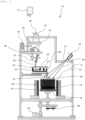
- a single-crystal production equipment 10 of the present Example assumes a case of producing a silicon single crystal having an optimum dopant composition.
- a single-crystal holding table 18 In the single-crystal production equipment 10, a single-crystal holding table 18, a holding table rotating mechanism 20 and an elevator apparatus 22 are arranged on the bottom of a single-crystal production chamber 11 which can be vacuum-evacuated and retain an inert gas atmosphere such as argon gas, and a seed single crystal 12 having a substantially circular cross-sectional shape is placed on the single-crystal holding table 18.
- an inert gas atmosphere such as argon gas
- the single-crystal production chamber 11 is a water-cooling structure which is capable of efficiently controlling the inner atmosphere.
- a hopper 33 which stores a granular raw material 52 is arranged.
- the hopper 33 has an opening on its lower part, and a spiral rod (not shown), which is equipped with a rotating mechanism and coated with polypropylene, is arranged inside the hopper 33 and rotated at all times during use.
- a spiral rod (not shown), which is equipped with a rotating mechanism and coated with polypropylene, is arranged inside the hopper 33 and rotated at all times during use.
- the opening on the lower part of the hopper 33 is directly connected to the single-crystal production chamber 11, and the hopper 33 and the single-crystal production chamber 11 are configured in such a manner to have the same internal atmosphere at all times.
- a granular raw material scraping equipment (hereinafter, also simply referred to as "scraping equipment”) 48 is arranged on a lateral side of the opening of the hopper 33.
- This scraping equipment 48 includes a propylene-coated receptacle having a spoon-like shape that is attached to a tip of a rod, and it is configured such that, by inserting this rod to the opening of the hopper 33 and then pulling out and half-rotating the rod with the granular raw material 52 being placed in the receptacle, the granular raw material 52 in the receptacle can be supplied onto a granular raw material quantitative supply equipment (hereinafter, also simply referred to as "quantitative supply equipment”) 50 positioned underneath the hopper 33.
- a granular raw material quantitative supply equipment hereinafter, also simply referred to as "quantitative supply equipment
- the quantitative supply equipment 50 adjusts the amount of the granular raw material 52 to be supplied while measuring the weight thereof and supplies a prescribed amount of the granular raw material 52 to a supply pipe 51 therebelow which has a supply position adjusting function.
- a symbol 60 represents a position adjusting mechanism.
- the hopper 33 in this embodiment stores a granular mixture obtained by mixing dopant-free granular silicon and a granular raw material doped with a dopant at a high concentration such that the granular mixture has an optimum composition, and this enables to surely maintain the composition ratio of the granular raw material 52 constant.
- the hopper 33 is used singly; however, the configuration is not restricted to this mode and, for example, a hopper for storing the dopant-free granular silicon and a hopper for storing the granular raw material doped with a dopant at a high concentration may be separately arranged.
- a known attachment-detachment mechanism 46 is arranged such that a storage container 47 which stores the granular raw material 52 can be attached and detached as desired.
- the attachment-detachment mechanism 46 includes an atmosphere controlling function for arbitrarily controlling the atmospheres inside the attachment-detachment mechanism 46 and the storage container 47.
- FIG. 1 shows a state where the storage container 47 is detached from the hopper 33.
- the storage container 47 that can be attached to and detached from the hopper 33 in this manner, the granular raw material 52 can be supplied to the hopper 33 at any time as required even in the midst of operating the single-crystal production equipment 10 to produce a single crystal. Therefore, it is not necessary to use a large hopper 33, and a reduction in the size of the single-crystal production equipment 10 can be realized.
- the granular raw material 52 supplied from the scraping equipment 48 is supplied to a prescribed position of a granular raw material melting vessel (hereinafter, also referred to as "melting vessel") 56 of a granular raw material melting apparatus through the supply pipe 51 in a prescribed amount using the quantitative supply equipment 50 which has a function of adjusting the supply amount while measuring the weight.
- a granular raw material melting vessel hereinafter, also referred to as "melting vessel”
- the position adjusting mechanism 60 which adjusts the position of an outlet at the lower end of the supply pipe 51, is attached.
- the melting vessel 56 which melts the granular raw material 52, have a multi-section structure divided into a "melting section” where the granular raw material 52 is melted and a “melt retaining section” where the resulting melt is retained; and that the melting vessel 56 have a function of preventing unmelted granular raw material 52 from being supplied downward along with the raw material melt 67.
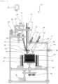
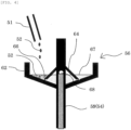
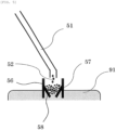
- the melting vessel 56 for example, such a boat-type melting vessel 56 as shown in FIGs. 1 and 3 or such a melting vessel 56 having a two-layer structure (umbrella-like structure) as shown in FIGs. 2 and 4 can be utilized. Further, in the case of producing a silicon single crystal, such a simple-type melting vessel 56 as shown in FIG. 5 can be utilized as well.
- a boat-shaped vessel 61 which receives the granular raw material 52 supplied from the supply pipe 51 is fitted inside a high-frequency induction heating equipment 55.
- a separation plate 63 having a groove 66 on a lower part is arranged inside the boat-shaped vessel 61, and the boat-shaped vessel 61 is divided by the separation plate 63 into the "melting section" and the "melt retaining section".
- the granular raw material 52 to be supplied to the boat-shaped vessel 61 through the supply pipe 51 may be directly supplied into the boat-shaped vessel 61; however, it is preferred to supply the granular raw material 52 into the boat-shaped vessel 61 using a funnel for granular raw material 53 since this makes it easier to supply the granular raw material 52 at a prescribed position.
- the raw material melt 67 retained in the boat-shaped vessel 61 has reached the height of an outlet 68 arranged on the boat-shaped vessel 61, the raw material melt 67 flows to the outside through the outlet 68 and is thereby supplied onto the seed single crystal below.
- the raw material melt 67 discharged from the outlet 68 is preferably supplied onto the seed single crystal 12 below through a tubular or rod-shaped (not shown) raw material melt guiding apparatus 54 which, as shown in FIG. 3 , extends from the lower end of the boat-shaped vessel 61 to immediately above the seed single crystal 12.
- the unmelted granular raw material 52 can be prevented from being supplied downward along with the raw material melt 67.
- the melting vessel 56 having a two-layer structure is constituted by a melting dish 62 and a separation dish 64 which is disposed thereon in such a manner to have an inverted V-shaped cross-section, and this melting vessel 56 is configured in such a manner to be divided between the melting dish 62 and the separation dish 64 into a melting section where the granular raw material 52 is melted and a melt retaining section where the resulting raw material melt 67 is retained.
- second infrared ray irradiation equipments 72 and 82 are used, and infrared rays 74 and 85 are irradiated to the melting vessel 56 from these second infrared ray irradiation equipments 72 and 82.
- the second infrared ray irradiation equipments 72 and 82 be arranged above and on a side of the melting vessel 56 as shown in FIG. 2 , respectively; however, they may both be arranged either above or on a side of the melting vessel 56.
- the second infrared ray irradiation equipments 72 and 82 laser irradiation equipments are preferably used; however, other than laser irradiation equipments, the second infrared ray irradiation equipments 72 and 82 may also be resistance heating equipments (particularly, carbon resistance heating equipments in the case of producing a silicon single crystal), or irradiation apparatuses configured such that, for example, an infrared ray emitted from an infrared lamp is reflected by the inner surface of an elliptical reflector. In this case, as the infrared lamp, a halogen lamp, a xenon lamp or the like can be used.
- the granular raw material 52 is heated and melted, and only the resulting raw material melt 67 moves to the central part through a groove 66 arranged at the lower end of the separation dish 64 and is retained in the separation dish 64.
- the raw material melt 67 retained in the separation dish 64 remains in the central part and, once the raw material melt 67 has reached the height of an outlet 68 arranged on a pipe 59 in the central part, the raw material melt 67 flows into the pipe 59 through the outlet 68 and is thereby supplied onto the upper surface of the seed single crystal below. By this, the unmelted granular raw material 52 can be prevented from dripping down along with the raw material melt 67.
- the pipe 59 arranged in the central part extends to immediately above the seed single crystal 12 and functions as the raw material melt guiding apparatus 54.
- the simple-type melting vessel 56 stores the granular raw material 52 supplied from the upper end and is constituted by a cylindrical section 57, whose lower end is inserted into an optimum melt 91 on the upper surface of the seed single crystal 12, and a funnel-shaped section 58, which is arranged inside the cylindrical section 57 and has an opening at the lower end.
- the second infrared ray irradiation equipments 72 and 82 may be used as in the case of the melting vessel 56 having a two-layer structure (umbrella-like structure) shown in FIG. 2 .
- melting vessel 56 having a two-layer structure (umbrella-like structure) and simple-type melting vessel 56 for example, platinum, iridium, quartz, silicon carbide, carbon, graphite, a carbon or graphite material whose surface has been converted to silicon carbide, or a carbon or graphite material whose surface has been coated with silicon carbide in advance, is selected in accordance with the raw material.
- the melting vessel 56 having a two-layer structure has a function of being rotated in the horizontal direction by a melting vessel rotating mechanism 70.
- a melting vessel rotating mechanism 70 By rotating the melting vessel 56 having a two-layer structure (umbrella-like structure) in this manner, the granular raw material 52 is evenly supplied from the supply pipe 51 into the melting vessel 56, so that the granular raw material 52 can be surely melted.
- a seed single crystal holding table (hereinafter, also simply referred to as "holding table") 18 is arranged in the lower part of the single-crystal production chamber 11.
- auxiliary heating equipment 86 is arranged on the outer side of the holding table 18, and the periphery of the auxiliary heating equipment 86 is constituted by the insulating material 87.
- the seed single crystal 12 is placed on the holding table 18, and the holding table 18 is rotated at a prescribed speed by the holding table rotating mechanism 20, whereby uneven irradiation of the upper surface of the seed single crystal 12 with the infrared ray (laser light) is reduced, and the resulting melt phase is thus allowed to have uniform temperature.
- the elevator apparatus 22 is attached to the holding table 18. This provides a configuration in which the height position of the melt phase formed on the upper surface of the seed single crystal 12 can be controlled to be optimal at all times.
- infrared ray transmitting windows 27, 73 and 84 are each arranged between the seed single crystal 12 and a first infrared ray irradiation equipment 26 for heating the seed single crystal 12 and between the melting vessel 56 and the respective second infrared ray irradiation equipments 72 and 82.
- the material of these infrared ray transmitting windows 27, 73 and 84 is not particularly restricted as long as it can transmit infrared rays; however, the infrared ray transmitting windows 27, 73 and 84 are preferably made of, for example, quartz.
- the single-crystal production equipment 10 is configured as described above, particularly in such a manner that the granular raw material 52 is converted into the raw material melt 67 using the boat-type melting vessel 56, the melting vessel 56 having a two-layer structure (umbrella-like structure) or the simple-type melting vessel 56 and only the raw material melt 67 is supplied to the upper surface of the seed single crystal 12; therefore, the single-crystal production equipment 10 is capable of producing a high-quality large single crystal with no negative crystal or crystal grain boundary, which has a uniform composition in both the vertical and horizontal directions at an optimum dopant concentration.
- the single-crystal production equipment 10 of the present invention includes no crucible, it is capable of producing a high-quality single crystal with no contamination from a crucible and without the generation of exsolution lamellae, which is one of the most serious defects in the case of, for example, using silicon.
- the seed single crystal 12 is placed on the holding table 18 in the single-crystal production chamber 11.
- a granular raw material pellet for optimum melt 90 which is prepared estimating the composition and the amount of an optimum melt phase to be formed, is placed on the upper surface of the seed single crystal 12.
- the single-crystal production chamber 11 is hermetically sealed, and the atmosphere inside the single-crystal production chamber 11 is vacuum-evacuated by a gas evacuation unit (not shown), followed by introduction of an inert atmosphere, such as argon gas, into the single-crystal production chamber 11.
- an optimum melt phase composed of the optimum melt 91 is formed by irradiating an infrared ray 28 to the upper surface of the seed single crystal 12 from the first infrared ray irradiation equipment 26.
- the scraping equipment 48, the quantitative supply equipment 50 and the vessel heating equipment, which are positioned above the seed single crystal 12, are put into operation so as to scrape the granular raw material 52 having an optimum composition out of the hopper 33, feed the granular raw material 52 into the melting vessel 56 through the supply pipe 51 at a prescribed rate, and supply the resulting raw material melt 67 into the optimum melt 91 on the upper surface of the seed single crystal 12.
- the infrared ray 28 becomes less likely to reach therebelow and, therefore, the temperature in the vicinity of a solid-liquid interface underneath the optimum melt 91 is lowered, as a result of which a solid phase starts to precipitate on the seed single crystal 12 as shown in FIG. 6(d) .
- the output of the first infrared ray irradiation equipment 26 is slowly lowered.
- the temperature is slowly lowered, and the single-crystal production chamber 11 is cooled to room temperature and then opened, after which the single crystal 92 on the holding table 18 is taken out as a product.
- the irradiation dose distribution of the infrared ray 28 is designed such that the surface of the single crystal 92 can be maintained as flat as possible throughout the production process.
- a granular raw material obtained by mixing the granular raw material 52 composed of a granular crystal base material (granular silicon) and a granular dopant material at an optimum composition is used.
- This mixed granular raw material 52 having an optimum composition is stored in the hopper 33 and, using the scraping equipment 48 and the quantitative supply equipment 50, the granular raw material 52 is dropped therefrom through the supply pipe 51 into the melting vessel 56, and only the resulting raw material melt 67 is supplied to the upper surface of the seed single crystal 12 below, whereby the processes from the supplying and the melting of the granular raw material 52 to the solidification of the single crystal 92 are continuously performed.
- the granular raw material 52 which is continuously supplied into the melting vessel 56, is heated and melted to obtain the raw material melt 67, and the single crystal 92 is precipitated by supplying the thus obtained raw material melt 67 to the upper surface of the seed single crystal 12; therefore, the resulting single crystal 92 has the same composition as that of the granular raw material 52 having an optimum composition.
- the crystal being produced is allowed to uniformly have an optimum composition.
- a single crystal having an optimum composition can thus be produced with good yield, and this consequently contributes to a reduction of the production cost.
- the single-crystal production equipment 10 of the present invention and a single-crystal production method using the single-crystal production equipment 10 have been described thus far; however, the present invention is not restricted to the above-described embodiments.
- a mixed granular raw material which is obtained by mixing a dopant-free high-purity silicon granular raw material and a granular raw material doped with phosphorus at a high concentration such that the resultant has a prescribed optimum composition, is used.
- a mixed granular raw material which is obtained by mixing a dopant-free high-purity silicon granular raw material and a granular raw material doped with boron at a high concentration such that the resultant has a prescribed optimum composition, is used.
- the particles of the granular raw material 52 preferably have a size of approximately 0.1 to 0.5 mm in diameter.
- the granular crystal base material is not restricted thereto, and any granular raw material 52 prepared in accordance with the substance to be produced can be used.
- plural first infrared ray irradiation equipments 26 each of which irradiates an infrared ray may be arranged, and the scraping equipment, the quantitative supply equipment, the supply pipe, the melting vessel and the vessel heating equipment may also each be arranged in a plural number. Defining the scraping equipment, the quantitative supply equipment, the supply pipe, the melting vessel and the vessel heating equipment as a single set, it is preferred to arrange the set in a plural number.
Landscapes
- Chemical & Material Sciences (AREA)
- Engineering & Computer Science (AREA)
- Crystallography & Structural Chemistry (AREA)
- Materials Engineering (AREA)
- Metallurgy (AREA)
- Organic Chemistry (AREA)
- Crystals, And After-Treatments Of Crystals (AREA)
Claims (22)
- Un équipement de production de monocristal destiné à produire un monocristal de grande taille en faisant fondre une matière première granulaire à l'aide d'un appareil de fusion de matière première granulaire, en fournissant la matière première fondue ainsi obtenue sous forme de masse fondue formée sur la surface supérieure d'un germe de monocristal en bas pour générer un mélange fondu, et en laissant ensuite un solide précipiter à partir dudit mélange fondu sous la forme d'un monocristal,
dans lequel ledit équipement de production de monocristal comprend, au moins:un appareil d'alimentation en matière première granulaire qui fournit une certaine quantité de ladite matière première granulaire vers le bas;ledit appareil de fusion de matière première granulaire qui chauffe et fait fondre ladite matière première granulaire fournie par ledit appareil d'alimentation en matière première granulaire et fournit la matière première fondue ainsi obtenue vers le bas; etun appareil de cristallisation qui permet à un monocristal de précipiter à partir dudit mélange fondu qui est formé à la réception d'une masse fondue formée lors de l'irradiation par rayons infrarouges provenant d'un premier équipement d'irradiation par rayons infrarouges sur la surface supérieure dudit germe de monocristal et de ladite matière première fondue fournie par ledit appareil de fusion de matière première granulaire.dans lequel ledit appareil de fusion de matière première granulaire comprend:un récipient de fusion de matière première granulaire qui reçoit ladite matière première granulaire (52), etun équipement de chauffage de récipient qui chauffe ledit récipient de fusion de matière première granulaire et fait ainsi fondre ledit récipient de fusion de matière première granulaire;dans lequel ledit récipient de fusion de matière première granulaire comprend:une section de fusion dans laquelle ladite matière première granulaire (52) est chauffée et fondue; etune section de retenue de masse fondue dans laquelle seule une masse fondue générée dans ladite section de fusion est retenue; etdans lequel ledit récipient de fusion de matière première granulaire est choisi parmi le groupe constitué par:- un récipient en forme de bateau (61), etune plaque de séparation (63) qui divise ledit récipient en forme de bateau (61)) en ladite section de fusion et ladite section de retenue de masse fondue et comprend une rainure (66) sur une partie inférieure,dans lequel l'appareil de guidage de matière première fondue, qui fournit ladite matière première fondue (67) déchargée dudit récipient de fusion de matière première granulaire sur ladite masse fondue formée sur la surface supérieure dudit germe de monocristal (12) ci-dessous, est disposé à une extrémité inférieure dudit récipient de fusion de matière première granulaire, ou- une cuvette de fusion (62), et
une cuvette de séparation (64) qui est disposée à l'intérieur de ladite cuvette de fusion (62), comporte une section transversale en forme de V inversé et comprend une rainure sur une partie inférieure, et
ledit récipient de fusion de matière première granulaire est configuré de manière à être divisé en ladite section de fusion et ladite section de retenue de masse fondue entre ladite cuvette de fusion (62) et ladite cuvette de séparation (64),dans lequel l'appareil de guidage de matière première fondue, qui fournit ladite matière première (67) fondue déchargée dudit récipient de fusion de matière première granulaire sur ladite masse fondue formée sur la surface supérieure dudit germe de monocristal (12) ci-dessous, est disposé à une extrémité inférieure dudit récipient de fusion de matière première granulaire, ou- dans lequel ledit récipient de fusion de matière première granulaire est constitué par:une section cylindrique (57), etune section en forme d'entonnoir (58) qui est disposée à l'intérieur de ladite section cylindrique (57) et présente une ouverture à une extrémité inférieure, etle côté intérieur de ladite section cylindrique (57) constitue ladite section de fusion et un espace entre le côté extérieur de ladite section cylindrique (57) et ladite section en forme d'entonnoir (58) constitue ladite section de retenue de masse fondue. - L'équipement de production de monocristal selon la revendication 1, dans lequel ledit appareil d'alimentation en matière première granulaire comprend:une trémie qui stocke ladite matière première granulaire; etun équipement d'alimentation quantitative en matière première granulaire qui contrôle ladite matière première granulaire dans ladite trémie pour qu'elle soit fournie à un débit prescrit et fournit une certaine quantité de ladite matière première granulaire vers le bas.
- L'équipement de production de monocristal selon la revendication 1 ou 2, dans lequel ledit appareil d'alimentation en matière première granulaire comprend un équipement de raclage de matière première granulaire qui racle ladite matière première granulaire hors de ladite trémie et fournit ladite matière première granulaire vers le bas.
- L'équipement de production de monocristal selon la revendication 2 ou 3, dans lequel ledit appareil d'alimentation en matière première granulaire comprend un tuyau d'alimentation à travers lequel ladite matière première granulaire fournie par ledit équipement d'alimentation quantitative en matière première granulaire est fournie à une position prescrite dudit appareil de fusion de matière premières granulaire en bas.
- L'équipement de production de monocristal selon la revendication 4, dans lequel un matériau dudit tuyau d'alimentation est le quartz.
- L'équipement de production de monocristal selon la revendication 2, dans lequel ladite trémie comprend un mécanisme de fixation-détachement pour fixer et détacher un réservoir de stockage stockant ladite matière première granulaire.
- L'équipement de production de monocristal selon la revendication 6, dans lequel ledit mécanisme de fixation-détachement a une fonction de contrôle de l'atmosphère permettant de contrôler arbitrairement l'atmosphère à l'intérieur dudit mécanisme de fixation-détachement et dudit réservoir de stockage.
- L'équipement de production de monocristal selon l'une quelconque des revendications 1 à 7, dans lequel ledit appareil de fusion de matière première granulaire et ledit appareil de cristallisation sont disposés à l'intérieur d'une chambre de production de monocristal.
- L'équipement de production de monocristal selon la revendication 8, dans lequel ledit appareil d'alimentation en matière première granulaire est disposé à l'intérieur de ladite chambre de production de monocristal.
- L'équipement de production de monocristal selon la revendication 8 ou 9, comprenant un équipement de contrôle d'atmosphère qui relie l'intérieur de ladite trémie à ladite chambre de production de monocristal, ou contrôle l'intérieur de ladite trémie et de ladite chambre de production de monocristal pour avoir la même atmosphère.
- L'équipement de production de monocristal selon l'une quelconque des revendications 2 à 10, dans lequel ladite trémie est constituée de plusieurs trémies dans lesquelles sont stockées chacune des matières premières granulaires ayant des compositions différentes.
- L'équipement de production de monocristal selon la revendication 1, dans lequel ledit équipement de chauffage de récipient est un deuxième équipement d'irradiation par rayons infrarouges.
- L'équipement de production de monocristal selon la revendication 1, dans lequel ledit équipement de chauffage de récipient est un équipement de chauffage par induction à haute fréquence.
- L'équipement de production de monocristal selon la revendication 1, dans lequel ledit équipement de chauffage de récipient est un équipement de chauffage à résistance.
- L'équipement de production de monocristal selon la revendication 1, dans lequel ledit récipient de fusion de matière première granulaire comprend un mécanisme de rotation de récipient de fusion qui tourne dans la direction horizontale.
- L'équipement de production de monocristal selon l'une quelconque des revendications 1 et 12 à 15, dans lequel une partie ou la totalité dudit récipient de fusion de matière première granulaire est composée de platine, d'iridium, de quartz, de carbure de silicium, de carbone, de graphite, d'un matériau de carbone ou de graphite dont la surface a été transformée en carbure de silicium, ou d'un matériau de carbone ou de graphite dont la surface a été préalablement recouverte de carbure de silicium.
- L'équipement de production de monocristal selon l'une quelconque des revendications 1 à 16, comprenant ledit appareil d'alimentation en matière première granulaire au pluriel.
- L'équipement de production de monocristal selon la revendication 17, comprenant ledit appareil de fusion de matière première granulaire au pluriel.
- L'équipement de production de monocristal selon l'une quelconque des revendications 8 à 18, dans lequel une table de maintien de monocristal, sur laquelle ledit germe de monocristal est placé, est disposée au fond de ladite chambre de production de monocristal.
- L'équipement de production de monocristal selon la revendication 19, dans lequel ladite table de maintien de monocristal comprend un mécanisme de rotation de table de maintien qui tourne dans la direction horizontale.
- L'équipement de production de monocristal selon la revendication 19 ou 20, dans lequel ladite table de maintien de monocristal comprend un appareil élévateur qui se déplace dans la direction verticale à une vitesse prescrite.
- L'équipement de production de monocristal selon l'une quelconque des revendications 1 à 21, dans lequel un équipement de chauffage auxiliaire est disposé sur le côté extérieur dudit germe de monocristal.
Applications Claiming Priority (1)
| Application Number | Priority Date | Filing Date | Title |
|---|---|---|---|
| PCT/JP2018/013162 WO2019186870A1 (fr) | 2018-03-29 | 2018-03-29 | Dispositif de fabrication d'un monocristal et procédé de fabrication d'un monocristal |
Publications (3)
| Publication Number | Publication Date |
|---|---|
| EP3572559A1 EP3572559A1 (fr) | 2019-11-27 |
| EP3572559A4 EP3572559A4 (fr) | 2020-01-22 |
| EP3572559B1 true EP3572559B1 (fr) | 2024-09-25 |
Family
ID=68057984
Family Applications (1)
| Application Number | Title | Priority Date | Filing Date |
|---|---|---|---|
| EP18785794.1A Active EP3572559B1 (fr) | 2018-03-29 | 2018-03-29 | Dispositif de fabrication d'un monocristal |
Country Status (5)
| Country | Link |
|---|---|
| US (1) | US20210222318A1 (fr) |
| EP (1) | EP3572559B1 (fr) |
| JP (1) | JP6607651B1 (fr) |
| CN (1) | CN110546314B (fr) |
| WO (1) | WO2019186870A1 (fr) |
Families Citing this family (1)
| Publication number | Priority date | Publication date | Assignee | Title |
|---|---|---|---|---|
| JP7633637B2 (ja) | 2020-07-28 | 2025-02-20 | 株式会社ノベルクリスタルテクノロジー | 単結晶製造装置及び単結晶の製造方法 |
Family Cites Families (14)
| Publication number | Priority date | Publication date | Assignee | Title |
|---|---|---|---|---|
| JPH06100394A (ja) * | 1992-09-17 | 1994-04-12 | Nkk Corp | 単結晶製造用原料供給方法及び装置 |
| JPH10273374A (ja) * | 1997-03-27 | 1998-10-13 | Kawasaki Steel Corp | シリコンの精製方法 |
| JPH11274537A (ja) * | 1998-03-24 | 1999-10-08 | Tokyo Denshi Yakin Kenkyusho:Kk | 大粒径多結晶シリコンの製造法 |
| JPH11292682A (ja) * | 1998-04-02 | 1999-10-26 | Shin Etsu Handotai Co Ltd | シリコン単結晶の製造方法および製造装置 |
| CN1224735C (zh) * | 1998-05-29 | 2005-10-26 | 东洋通信机株式会社 | 单晶制造装置、单晶制造方法及单晶体 |
| CN1330798C (zh) * | 2004-05-31 | 2007-08-08 | 南开大学 | 熔体注入法生长近化学比铌酸锂晶体系统及其工艺 |
| JP4317575B2 (ja) * | 2005-08-19 | 2009-08-19 | Sumcoソーラー株式会社 | シリコン電磁鋳造装置およびその操作方法 |
| WO2009081811A1 (fr) | 2007-12-25 | 2009-07-02 | Crystal Systems Corporation | Appareil de fusion à zone flottante |
| JP4307516B1 (ja) * | 2008-11-25 | 2009-08-05 | 佑吉 堀岡 | 結晶成長装置及び結晶成長方法 |
| RU2418109C1 (ru) * | 2009-11-09 | 2011-05-10 | Инновационно-технический центр Общество с ограниченной ответственностью "СИТИС" | Установка для получения монокристаллов |
| JP6126370B2 (ja) * | 2012-12-12 | 2017-05-10 | 三光機械株式会社 | 粒状原料供給装置 |
| CN104328483A (zh) * | 2014-11-13 | 2015-02-04 | 吴晟 | 一种单晶生长方法及装置 |
| WO2018003386A1 (fr) * | 2016-06-29 | 2018-01-04 | 株式会社クリスタルシステム | Appareil de production d'un monocristal et procédé de production d'un monocristal |
| US20190032242A1 (en) * | 2016-07-28 | 2019-01-31 | Crystal Systems Corporation | Single-Crystal Production Equipment |
-
2018
- 2018-03-29 WO PCT/JP2018/013162 patent/WO2019186870A1/fr not_active Ceased
- 2018-03-29 US US16/303,254 patent/US20210222318A1/en not_active Abandoned
- 2018-03-29 EP EP18785794.1A patent/EP3572559B1/fr active Active
- 2018-03-29 CN CN201880001867.5A patent/CN110546314B/zh active Active
- 2018-03-29 JP JP2018537687A patent/JP6607651B1/ja active Active
Also Published As
| Publication number | Publication date |
|---|---|
| CN110546314A (zh) | 2019-12-06 |
| WO2019186870A1 (fr) | 2019-10-03 |
| US20210222318A1 (en) | 2021-07-22 |
| EP3572559A4 (fr) | 2020-01-22 |
| JP6607651B1 (ja) | 2019-11-20 |
| JPWO2019186870A1 (ja) | 2020-04-30 |
| EP3572559A1 (fr) | 2019-11-27 |
| CN110546314B (zh) | 2021-04-02 |
Similar Documents
| Publication | Publication Date | Title |
|---|---|---|
| US11346016B2 (en) | System for introducing dopant into a melt of semiconductor or solar-grade material via a feed tube | |
| CN107849732B (zh) | 单晶制造装置和单晶制造方法 | |
| US20210222320A1 (en) | Method of Producing a Single-Crystal | |
| US20070056504A1 (en) | Method and apparatus to produce single crystal ingot of uniform axial resistivity | |
| JP2020063163A (ja) | 単結晶製造装置 | |
| EP3572559B1 (fr) | Dispositif de fabrication d'un monocristal | |
| EP3572560B1 (fr) | Dispositif de fabrication d'un monocristal | |
| JP6708173B2 (ja) | リチャージ管及び単結晶の製造方法 | |
| JP6039513B2 (ja) | 結晶成長装置および結晶成長方法 | |
| TW202328509A (zh) | 用於涉及矽進料管之惰性氣體控制之單晶矽錠生長之方法 | |
| JP4459519B2 (ja) | 化合物原料及び化合物単結晶の製造方法 |
Legal Events
| Date | Code | Title | Description |
|---|---|---|---|
| STAA | Information on the status of an ep patent application or granted ep patent |
Free format text: STATUS: UNKNOWN |
|
| STAA | Information on the status of an ep patent application or granted ep patent |
Free format text: STATUS: THE INTERNATIONAL PUBLICATION HAS BEEN MADE |
|
| PUAI | Public reference made under article 153(3) epc to a published international application that has entered the european phase |
Free format text: ORIGINAL CODE: 0009012 |
|
| STAA | Information on the status of an ep patent application or granted ep patent |
Free format text: STATUS: REQUEST FOR EXAMINATION WAS MADE |
|
| 17P | Request for examination filed |
Effective date: 20181024 |
|
| AK | Designated contracting states |
Kind code of ref document: A1 Designated state(s): AL AT BE BG CH CY CZ DE DK EE ES FI FR GB GR HR HU IE IS IT LI LT LU LV MC MK MT NL NO PL PT RO RS SE SI SK SM TR |
|
| AX | Request for extension of the european patent |
Extension state: BA ME |
|
| A4 | Supplementary search report drawn up and despatched |
Effective date: 20191220 |
|
| RIC1 | Information provided on ipc code assigned before grant |
Ipc: C30B 11/08 20060101ALI20191216BHEP Ipc: C30B 11/00 20060101ALI20191216BHEP Ipc: C30B 13/00 20060101AFI20191216BHEP |
|
| STAA | Information on the status of an ep patent application or granted ep patent |
Free format text: STATUS: EXAMINATION IS IN PROGRESS |
|
| 17Q | First examination report despatched |
Effective date: 20210409 |
|
| DAV | Request for validation of the european patent (deleted) | ||
| DAX | Request for extension of the european patent (deleted) | ||
| GRAP | Despatch of communication of intention to grant a patent |
Free format text: ORIGINAL CODE: EPIDOSNIGR1 |
|
| STAA | Information on the status of an ep patent application or granted ep patent |
Free format text: STATUS: GRANT OF PATENT IS INTENDED |
|
| INTG | Intention to grant announced |
Effective date: 20240322 |
|
| GRAS | Grant fee paid |
Free format text: ORIGINAL CODE: EPIDOSNIGR3 |
|
| P01 | Opt-out of the competence of the unified patent court (upc) registered |
Free format text: CASE NUMBER: APP_37729/2024 Effective date: 20240625 |
|
| GRAA | (expected) grant |
Free format text: ORIGINAL CODE: 0009210 |
|
| STAA | Information on the status of an ep patent application or granted ep patent |
Free format text: STATUS: THE PATENT HAS BEEN GRANTED |
|
| AK | Designated contracting states |
Kind code of ref document: B1 Designated state(s): AL AT BE BG CH CY CZ DE DK EE ES FI FR GB GR HR HU IE IS IT LI LT LU LV MC MK MT NL NO PL PT RO RS SE SI SK SM TR |
|
| REG | Reference to a national code |
Ref country code: GB Ref legal event code: FG4D |
|
| REG | Reference to a national code |
Ref country code: CH Ref legal event code: EP |
|
| REG | Reference to a national code |
Ref country code: DE Ref legal event code: R096 Ref document number: 602018074740 Country of ref document: DE |
|
| REG | Reference to a national code |
Ref country code: IE Ref legal event code: FG4D |
|
| REG | Reference to a national code |
Ref country code: LT Ref legal event code: MG9D |
|
| PG25 | Lapsed in a contracting state [announced via postgrant information from national office to epo] |
Ref country code: NO Free format text: LAPSE BECAUSE OF FAILURE TO SUBMIT A TRANSLATION OF THE DESCRIPTION OR TO PAY THE FEE WITHIN THE PRESCRIBED TIME-LIMIT Effective date: 20241225 |
|
| PG25 | Lapsed in a contracting state [announced via postgrant information from national office to epo] |
Ref country code: GR Free format text: LAPSE BECAUSE OF FAILURE TO SUBMIT A TRANSLATION OF THE DESCRIPTION OR TO PAY THE FEE WITHIN THE PRESCRIBED TIME-LIMIT Effective date: 20241226 Ref country code: FI Free format text: LAPSE BECAUSE OF FAILURE TO SUBMIT A TRANSLATION OF THE DESCRIPTION OR TO PAY THE FEE WITHIN THE PRESCRIBED TIME-LIMIT Effective date: 20240925 |
|
| PG25 | Lapsed in a contracting state [announced via postgrant information from national office to epo] |
Ref country code: BG Free format text: LAPSE BECAUSE OF FAILURE TO SUBMIT A TRANSLATION OF THE DESCRIPTION OR TO PAY THE FEE WITHIN THE PRESCRIBED TIME-LIMIT Effective date: 20240925 |
|
| PG25 | Lapsed in a contracting state [announced via postgrant information from national office to epo] |
Ref country code: LV Free format text: LAPSE BECAUSE OF FAILURE TO SUBMIT A TRANSLATION OF THE DESCRIPTION OR TO PAY THE FEE WITHIN THE PRESCRIBED TIME-LIMIT Effective date: 20240925 |
|
| PG25 | Lapsed in a contracting state [announced via postgrant information from national office to epo] |
Ref country code: RS Free format text: LAPSE BECAUSE OF FAILURE TO SUBMIT A TRANSLATION OF THE DESCRIPTION OR TO PAY THE FEE WITHIN THE PRESCRIBED TIME-LIMIT Effective date: 20241225 |
|
| REG | Reference to a national code |
Ref country code: NL Ref legal event code: MP Effective date: 20240925 |
|
| PG25 | Lapsed in a contracting state [announced via postgrant information from national office to epo] |
Ref country code: RS Free format text: LAPSE BECAUSE OF FAILURE TO SUBMIT A TRANSLATION OF THE DESCRIPTION OR TO PAY THE FEE WITHIN THE PRESCRIBED TIME-LIMIT Effective date: 20241225 Ref country code: NO Free format text: LAPSE BECAUSE OF FAILURE TO SUBMIT A TRANSLATION OF THE DESCRIPTION OR TO PAY THE FEE WITHIN THE PRESCRIBED TIME-LIMIT Effective date: 20241225 Ref country code: LV Free format text: LAPSE BECAUSE OF FAILURE TO SUBMIT A TRANSLATION OF THE DESCRIPTION OR TO PAY THE FEE WITHIN THE PRESCRIBED TIME-LIMIT Effective date: 20240925 Ref country code: GR Free format text: LAPSE BECAUSE OF FAILURE TO SUBMIT A TRANSLATION OF THE DESCRIPTION OR TO PAY THE FEE WITHIN THE PRESCRIBED TIME-LIMIT Effective date: 20241226 Ref country code: FI Free format text: LAPSE BECAUSE OF FAILURE TO SUBMIT A TRANSLATION OF THE DESCRIPTION OR TO PAY THE FEE WITHIN THE PRESCRIBED TIME-LIMIT Effective date: 20240925 Ref country code: BG Free format text: LAPSE BECAUSE OF FAILURE TO SUBMIT A TRANSLATION OF THE DESCRIPTION OR TO PAY THE FEE WITHIN THE PRESCRIBED TIME-LIMIT Effective date: 20240925 |
|
| REG | Reference to a national code |
Ref country code: AT Ref legal event code: MK05 Ref document number: 1726700 Country of ref document: AT Kind code of ref document: T Effective date: 20240925 |
|
| PG25 | Lapsed in a contracting state [announced via postgrant information from national office to epo] |
Ref country code: NL Free format text: LAPSE BECAUSE OF FAILURE TO SUBMIT A TRANSLATION OF THE DESCRIPTION OR TO PAY THE FEE WITHIN THE PRESCRIBED TIME-LIMIT Effective date: 20240925 |
|
| PG25 | Lapsed in a contracting state [announced via postgrant information from national office to epo] |
Ref country code: PT Free format text: LAPSE BECAUSE OF FAILURE TO SUBMIT A TRANSLATION OF THE DESCRIPTION OR TO PAY THE FEE WITHIN THE PRESCRIBED TIME-LIMIT Effective date: 20250127 Ref country code: IS Free format text: LAPSE BECAUSE OF FAILURE TO SUBMIT A TRANSLATION OF THE DESCRIPTION OR TO PAY THE FEE WITHIN THE PRESCRIBED TIME-LIMIT Effective date: 20250125 |
|
| PGFP | Annual fee paid to national office [announced via postgrant information from national office to epo] |
Ref country code: DE Payment date: 20250326 Year of fee payment: 8 |
|
| PG25 | Lapsed in a contracting state [announced via postgrant information from national office to epo] |
Ref country code: RO Free format text: LAPSE BECAUSE OF FAILURE TO SUBMIT A TRANSLATION OF THE DESCRIPTION OR TO PAY THE FEE WITHIN THE PRESCRIBED TIME-LIMIT Effective date: 20240925 Ref country code: SM Free format text: LAPSE BECAUSE OF FAILURE TO SUBMIT A TRANSLATION OF THE DESCRIPTION OR TO PAY THE FEE WITHIN THE PRESCRIBED TIME-LIMIT Effective date: 20240925 |
|
| PG25 | Lapsed in a contracting state [announced via postgrant information from national office to epo] |
Ref country code: ES Free format text: LAPSE BECAUSE OF FAILURE TO SUBMIT A TRANSLATION OF THE DESCRIPTION OR TO PAY THE FEE WITHIN THE PRESCRIBED TIME-LIMIT Effective date: 20240925 |
|
| PG25 | Lapsed in a contracting state [announced via postgrant information from national office to epo] |
Ref country code: EE Free format text: LAPSE BECAUSE OF FAILURE TO SUBMIT A TRANSLATION OF THE DESCRIPTION OR TO PAY THE FEE WITHIN THE PRESCRIBED TIME-LIMIT Effective date: 20240925 Ref country code: AT Free format text: LAPSE BECAUSE OF FAILURE TO SUBMIT A TRANSLATION OF THE DESCRIPTION OR TO PAY THE FEE WITHIN THE PRESCRIBED TIME-LIMIT Effective date: 20240925 |
|
| PG25 | Lapsed in a contracting state [announced via postgrant information from national office to epo] |
Ref country code: CZ Free format text: LAPSE BECAUSE OF FAILURE TO SUBMIT A TRANSLATION OF THE DESCRIPTION OR TO PAY THE FEE WITHIN THE PRESCRIBED TIME-LIMIT Effective date: 20240925 Ref country code: PL Free format text: LAPSE BECAUSE OF FAILURE TO SUBMIT A TRANSLATION OF THE DESCRIPTION OR TO PAY THE FEE WITHIN THE PRESCRIBED TIME-LIMIT Effective date: 20240925 |
|
| PGFP | Annual fee paid to national office [announced via postgrant information from national office to epo] |
Ref country code: FR Payment date: 20250326 Year of fee payment: 8 |
|
| PG25 | Lapsed in a contracting state [announced via postgrant information from national office to epo] |
Ref country code: SK Free format text: LAPSE BECAUSE OF FAILURE TO SUBMIT A TRANSLATION OF THE DESCRIPTION OR TO PAY THE FEE WITHIN THE PRESCRIBED TIME-LIMIT Effective date: 20240925 |
|
| PGFP | Annual fee paid to national office [announced via postgrant information from national office to epo] |
Ref country code: IT Payment date: 20250325 Year of fee payment: 8 Ref country code: GB Payment date: 20250324 Year of fee payment: 8 |
|
| REG | Reference to a national code |
Ref country code: DE Ref legal event code: R097 Ref document number: 602018074740 Country of ref document: DE |
|
| PG25 | Lapsed in a contracting state [announced via postgrant information from national office to epo] |
Ref country code: DK Free format text: LAPSE BECAUSE OF FAILURE TO SUBMIT A TRANSLATION OF THE DESCRIPTION OR TO PAY THE FEE WITHIN THE PRESCRIBED TIME-LIMIT Effective date: 20240925 |
|
| PLBE | No opposition filed within time limit |
Free format text: ORIGINAL CODE: 0009261 |
|
| STAA | Information on the status of an ep patent application or granted ep patent |
Free format text: STATUS: NO OPPOSITION FILED WITHIN TIME LIMIT |
|
| 26N | No opposition filed |
Effective date: 20250626 |
|
| PG25 | Lapsed in a contracting state [announced via postgrant information from national office to epo] |
Ref country code: SE Free format text: LAPSE BECAUSE OF FAILURE TO SUBMIT A TRANSLATION OF THE DESCRIPTION OR TO PAY THE FEE WITHIN THE PRESCRIBED TIME-LIMIT Effective date: 20240925 |
|
| PG25 | Lapsed in a contracting state [announced via postgrant information from national office to epo] |
Ref country code: MC Free format text: LAPSE BECAUSE OF FAILURE TO SUBMIT A TRANSLATION OF THE DESCRIPTION OR TO PAY THE FEE WITHIN THE PRESCRIBED TIME-LIMIT Effective date: 20240925 |
|
| REG | Reference to a national code |
Ref country code: CH Ref legal event code: H13 Free format text: ST27 STATUS EVENT CODE: U-0-0-H10-H13 (AS PROVIDED BY THE NATIONAL OFFICE) Effective date: 20251023 |
|
| PG25 | Lapsed in a contracting state [announced via postgrant information from national office to epo] |
Ref country code: LU Free format text: LAPSE BECAUSE OF NON-PAYMENT OF DUE FEES Effective date: 20250329 |
|
| REG | Reference to a national code |
Ref country code: BE Ref legal event code: MM Effective date: 20250331 |
|
| PG25 | Lapsed in a contracting state [announced via postgrant information from national office to epo] |
Ref country code: HR Free format text: LAPSE BECAUSE OF FAILURE TO SUBMIT A TRANSLATION OF THE DESCRIPTION OR TO PAY THE FEE WITHIN THE PRESCRIBED TIME-LIMIT Effective date: 20240925 |
|
| PG25 | Lapsed in a contracting state [announced via postgrant information from national office to epo] |
Ref country code: BE Free format text: LAPSE BECAUSE OF NON-PAYMENT OF DUE FEES Effective date: 20250331 |
|
| PG25 | Lapsed in a contracting state [announced via postgrant information from national office to epo] |
Ref country code: CH Free format text: LAPSE BECAUSE OF NON-PAYMENT OF DUE FEES Effective date: 20250331 |
|
| PG25 | Lapsed in a contracting state [announced via postgrant information from national office to epo] |
Ref country code: IE Free format text: LAPSE BECAUSE OF NON-PAYMENT OF DUE FEES Effective date: 20250329 |