WO2019186870A1 - Dispositif de fabrication d'un monocristal et procédé de fabrication d'un monocristal - Google Patents
Dispositif de fabrication d'un monocristal et procédé de fabrication d'un monocristal Download PDFInfo
- Publication number
- WO2019186870A1 WO2019186870A1 PCT/JP2018/013162 JP2018013162W WO2019186870A1 WO 2019186870 A1 WO2019186870 A1 WO 2019186870A1 JP 2018013162 W JP2018013162 W JP 2018013162W WO 2019186870 A1 WO2019186870 A1 WO 2019186870A1
- Authority
- WO
- WIPO (PCT)
- Prior art keywords
- raw material
- single crystal
- granular raw
- melt
- melting
- Prior art date
- Legal status (The legal status is an assumption and is not a legal conclusion. Google has not performed a legal analysis and makes no representation as to the accuracy of the status listed.)
- Ceased
Links
Images



Classifications
-
- C—CHEMISTRY; METALLURGY
- C30—CRYSTAL GROWTH
- C30B—SINGLE-CRYSTAL GROWTH; UNIDIRECTIONAL SOLIDIFICATION OF EUTECTIC MATERIAL OR UNIDIRECTIONAL DEMIXING OF EUTECTOID MATERIAL; REFINING BY ZONE-MELTING OF MATERIAL; PRODUCTION OF A HOMOGENEOUS POLYCRYSTALLINE MATERIAL WITH DEFINED STRUCTURE; SINGLE CRYSTALS OR HOMOGENEOUS POLYCRYSTALLINE MATERIAL WITH DEFINED STRUCTURE; AFTER-TREATMENT OF SINGLE CRYSTALS OR A HOMOGENEOUS POLYCRYSTALLINE MATERIAL WITH DEFINED STRUCTURE; APPARATUS THEREFOR
- C30B11/00—Single-crystal growth by normal freezing or freezing under temperature gradient, e.g. Bridgman-Stockbarger method
- C30B11/04—Single-crystal growth by normal freezing or freezing under temperature gradient, e.g. Bridgman-Stockbarger method adding crystallising materials or reactants forming it in situ to the melt
- C30B11/08—Single-crystal growth by normal freezing or freezing under temperature gradient, e.g. Bridgman-Stockbarger method adding crystallising materials or reactants forming it in situ to the melt every component of the crystal composition being added during the crystallisation
- C30B11/10—Solid or liquid components, e.g. Verneuil method
-
- C—CHEMISTRY; METALLURGY
- C30—CRYSTAL GROWTH
- C30B—SINGLE-CRYSTAL GROWTH; UNIDIRECTIONAL SOLIDIFICATION OF EUTECTIC MATERIAL OR UNIDIRECTIONAL DEMIXING OF EUTECTOID MATERIAL; REFINING BY ZONE-MELTING OF MATERIAL; PRODUCTION OF A HOMOGENEOUS POLYCRYSTALLINE MATERIAL WITH DEFINED STRUCTURE; SINGLE CRYSTALS OR HOMOGENEOUS POLYCRYSTALLINE MATERIAL WITH DEFINED STRUCTURE; AFTER-TREATMENT OF SINGLE CRYSTALS OR A HOMOGENEOUS POLYCRYSTALLINE MATERIAL WITH DEFINED STRUCTURE; APPARATUS THEREFOR
- C30B11/00—Single-crystal growth by normal freezing or freezing under temperature gradient, e.g. Bridgman-Stockbarger method
- C30B11/003—Heating or cooling of the melt or the crystallised material
-
- C—CHEMISTRY; METALLURGY
- C30—CRYSTAL GROWTH
- C30B—SINGLE-CRYSTAL GROWTH; UNIDIRECTIONAL SOLIDIFICATION OF EUTECTIC MATERIAL OR UNIDIRECTIONAL DEMIXING OF EUTECTOID MATERIAL; REFINING BY ZONE-MELTING OF MATERIAL; PRODUCTION OF A HOMOGENEOUS POLYCRYSTALLINE MATERIAL WITH DEFINED STRUCTURE; SINGLE CRYSTALS OR HOMOGENEOUS POLYCRYSTALLINE MATERIAL WITH DEFINED STRUCTURE; AFTER-TREATMENT OF SINGLE CRYSTALS OR A HOMOGENEOUS POLYCRYSTALLINE MATERIAL WITH DEFINED STRUCTURE; APPARATUS THEREFOR
- C30B11/00—Single-crystal growth by normal freezing or freezing under temperature gradient, e.g. Bridgman-Stockbarger method
- C30B11/001—Continuous growth
-
- C—CHEMISTRY; METALLURGY
- C30—CRYSTAL GROWTH
- C30B—SINGLE-CRYSTAL GROWTH; UNIDIRECTIONAL SOLIDIFICATION OF EUTECTIC MATERIAL OR UNIDIRECTIONAL DEMIXING OF EUTECTOID MATERIAL; REFINING BY ZONE-MELTING OF MATERIAL; PRODUCTION OF A HOMOGENEOUS POLYCRYSTALLINE MATERIAL WITH DEFINED STRUCTURE; SINGLE CRYSTALS OR HOMOGENEOUS POLYCRYSTALLINE MATERIAL WITH DEFINED STRUCTURE; AFTER-TREATMENT OF SINGLE CRYSTALS OR A HOMOGENEOUS POLYCRYSTALLINE MATERIAL WITH DEFINED STRUCTURE; APPARATUS THEREFOR
- C30B11/00—Single-crystal growth by normal freezing or freezing under temperature gradient, e.g. Bridgman-Stockbarger method
- C30B11/006—Controlling or regulating
-
- C—CHEMISTRY; METALLURGY
- C30—CRYSTAL GROWTH
- C30B—SINGLE-CRYSTAL GROWTH; UNIDIRECTIONAL SOLIDIFICATION OF EUTECTIC MATERIAL OR UNIDIRECTIONAL DEMIXING OF EUTECTOID MATERIAL; REFINING BY ZONE-MELTING OF MATERIAL; PRODUCTION OF A HOMOGENEOUS POLYCRYSTALLINE MATERIAL WITH DEFINED STRUCTURE; SINGLE CRYSTALS OR HOMOGENEOUS POLYCRYSTALLINE MATERIAL WITH DEFINED STRUCTURE; AFTER-TREATMENT OF SINGLE CRYSTALS OR A HOMOGENEOUS POLYCRYSTALLINE MATERIAL WITH DEFINED STRUCTURE; APPARATUS THEREFOR
- C30B11/00—Single-crystal growth by normal freezing or freezing under temperature gradient, e.g. Bridgman-Stockbarger method
- C30B11/04—Single-crystal growth by normal freezing or freezing under temperature gradient, e.g. Bridgman-Stockbarger method adding crystallising materials or reactants forming it in situ to the melt
- C30B11/08—Single-crystal growth by normal freezing or freezing under temperature gradient, e.g. Bridgman-Stockbarger method adding crystallising materials or reactants forming it in situ to the melt every component of the crystal composition being added during the crystallisation
-
- C—CHEMISTRY; METALLURGY
- C30—CRYSTAL GROWTH
- C30B—SINGLE-CRYSTAL GROWTH; UNIDIRECTIONAL SOLIDIFICATION OF EUTECTIC MATERIAL OR UNIDIRECTIONAL DEMIXING OF EUTECTOID MATERIAL; REFINING BY ZONE-MELTING OF MATERIAL; PRODUCTION OF A HOMOGENEOUS POLYCRYSTALLINE MATERIAL WITH DEFINED STRUCTURE; SINGLE CRYSTALS OR HOMOGENEOUS POLYCRYSTALLINE MATERIAL WITH DEFINED STRUCTURE; AFTER-TREATMENT OF SINGLE CRYSTALS OR A HOMOGENEOUS POLYCRYSTALLINE MATERIAL WITH DEFINED STRUCTURE; APPARATUS THEREFOR
- C30B13/00—Single-crystal growth by zone-melting; Refining by zone-melting
- C30B13/08—Single-crystal growth by zone-melting; Refining by zone-melting adding crystallising materials or reactants forming it in situ to the molten zone
-
- C—CHEMISTRY; METALLURGY
- C30—CRYSTAL GROWTH
- C30B—SINGLE-CRYSTAL GROWTH; UNIDIRECTIONAL SOLIDIFICATION OF EUTECTIC MATERIAL OR UNIDIRECTIONAL DEMIXING OF EUTECTOID MATERIAL; REFINING BY ZONE-MELTING OF MATERIAL; PRODUCTION OF A HOMOGENEOUS POLYCRYSTALLINE MATERIAL WITH DEFINED STRUCTURE; SINGLE CRYSTALS OR HOMOGENEOUS POLYCRYSTALLINE MATERIAL WITH DEFINED STRUCTURE; AFTER-TREATMENT OF SINGLE CRYSTALS OR A HOMOGENEOUS POLYCRYSTALLINE MATERIAL WITH DEFINED STRUCTURE; APPARATUS THEREFOR
- C30B15/00—Single-crystal growth by pulling from a melt, e.g. Czochralski method
- C30B15/02—Single-crystal growth by pulling from a melt, e.g. Czochralski method adding crystallising materials or reactants forming it in situ to the melt
-
- C—CHEMISTRY; METALLURGY
- C30—CRYSTAL GROWTH
- C30B—SINGLE-CRYSTAL GROWTH; UNIDIRECTIONAL SOLIDIFICATION OF EUTECTIC MATERIAL OR UNIDIRECTIONAL DEMIXING OF EUTECTOID MATERIAL; REFINING BY ZONE-MELTING OF MATERIAL; PRODUCTION OF A HOMOGENEOUS POLYCRYSTALLINE MATERIAL WITH DEFINED STRUCTURE; SINGLE CRYSTALS OR HOMOGENEOUS POLYCRYSTALLINE MATERIAL WITH DEFINED STRUCTURE; AFTER-TREATMENT OF SINGLE CRYSTALS OR A HOMOGENEOUS POLYCRYSTALLINE MATERIAL WITH DEFINED STRUCTURE; APPARATUS THEREFOR
- C30B35/00—Apparatus not otherwise provided for, specially adapted for the growth, production or after-treatment of single crystals or of a homogeneous polycrystalline material with defined structure
- C30B35/002—Crucibles or containers
Definitions
- the present invention relates to a single crystal production apparatus for producing a high-quality single crystal with high efficiency while homogenizing the composition to the optimum composition, and a large-sized optimum additive composition single crystal (hereinafter referred to as optimum crystal) using this single crystal production apparatus. Also referred to as a single crystal manufacturing method.
- a single crystal refers to a material in which atoms constituting the substance are neatly arranged over the entire area according to a prescribed format. Such single crystals are used in various fields such as semiconductor materials and optical materials because the original characteristics of the substance are remarkably exhibited with little disorder of atomic arrangement.
- Single crystals such as silicon (Si), the main semiconductor material, lutetium oxalate (LSO; Lu 2 SiO 5 ), the phosphor material, and yttrium aluminum garnet (YAG; Y 3 Al 5 O 12 ), the laser material, , Both are products manufactured by the “pull-up method”.
- the above-mentioned single crystal materials such as Si, LSO, and YAG are each made by adding useful additives to necessary concentrations.
- Si it is used as an N-type semiconductor added with phosphorus or a P-type semiconductor added with boron.
- cerium is added to LSO, and neodymium is added to YAG.
- the raw material is melted in a suitable crucible, and the seed single crystal is immersed in the resulting melt to increase the thickness.
- the single crystal is manufactured by pulling up.
- This method is a method belonging to the so-called unidirectional solidification method in which the entire melt is solidified from the top to the bottom. Therefore, due to the segregation phenomenon that occurs when producing a single crystal as a solid from the melt, There is a disadvantage that the additive concentration is not constant.
- the additive concentration in the melt and the additive concentration in the solidified single crystal are not the same, and solidification proceeds at a ratio defined by the substance. This ratio is called the “partition coefficient”, and when the concentration in the melt is 1, the concentration in the resulting crystal is, for example, about 0.35 when phosphorus is added to silicon, and when Ce is added to LSO. About 0.2.
- the additive concentration in the produced single crystal becomes lower than in the melt, and the difference remains in the melt. Therefore, as the growth proceeds, the additive concentration in the melt gradually increases. Since the ratio of the additive concentration in the melt and the additive concentration in the single crystal to be formed is defined by the distribution coefficient, if the crystallization proceeds and the additive concentration in the melt increases, The additive concentration will also increase gradually.
- the floating zone melting method is known as another method for producing a single crystal material.
- This floating zone melting method generally melts the lower end of a raw material rod formed into a round bar shape and the upper surface of a seed single crystal arranged below the raw material rod, and joins the melts of both. While holding the melt with surface tension between the upper raw material rod and the lower seed single crystal, the upper part of the melt melts the raw material, and the lower part of the melt precipitates a single crystal as a solid from the melt.
- This is a method for producing a single crystal rod.
- high-frequency floating zone melting method using high-frequency induction
- infrared floating zone melting method infrared FZ method
- the supply of the raw material into the melt and the precipitation of the single crystal from the melt are continued, so the additive concentration in the obtained single crystal and the addition in the raw material
- This is a single crystal manufacturing method in which the product concentration is the same in a steady state and a single crystal product having a uniform composition can be obtained.
- no crucible since no crucible is used, it is possible to produce a high-purity single crystal that does not contain a crucible component, and it is also a single crystal production method that can be applied to materials for which no suitable crucible material is found.
- the high-frequency FZ method requires a dense and high-quality raw material rod in order to continue stable high-frequency induction, and it has been pointed out that it is difficult to apply to insulator materials.
- the infrared FZ method can be widely applied from an insulator material to a good conductor material, and although the raw material bar is known to have an advantage such as not necessarily requiring high density, the diameter of a manufacturable single crystal rod However, it is as small as 20-30 mm at most, and is used exclusively as research and development equipment.
- being able to irradiate the material with infrared rays to form a melt means that the infrared rays are absorbed by the material and become heat. Since the absorption of infrared rays proceeds while passing through the melt, the amount of infrared rays that can reach the deep portion gradually decreases. For this reason, since temperature falls as it leaves
- the distance between the upper raw material rod and the lower crystal rod is narrower than that of the outer peripheral portion.
- an inclined irradiation type infrared FZ method (hereinafter also referred to as an inclined FZ method) that irradiates infrared rays from obliquely upward to downward.
- an inclined FZ method the melt formed by melting the raw material naturally flows and moves downward due to gravity and rides on the seed single crystal disposed below.
- this gradient FZ method can stably hold the melt on the seed single crystal even if the diameter of the seed single crystal is large, and there is no restriction on the diameter of the single crystal that can be grown. .
- the raw material rod is normally melted by locally heating the lower part of the raw material rod, but when a large material rod made of a material having relatively high thermal conductivity such as silicon is locally heated to melt. Because heat is transferred to the whole large-sized raw material rod, a large amount of energy that takes it into account is required.
- the gradient FZ method is a method of producing a single crystal by irradiating the raw material with infrared rays and melting and solidifying it, and a method of forming and using the granular raw material in a rod shape is generally used, but the granular raw material is used as it is. It is a method that may be melted and solidified as a single crystal.
- the present inventor instead of using the conventional method of forming the granular raw material into a rod shape, the raw material melt obtained by melting the granular raw material as it is is formed on the upper surface of the seed single crystal.
- the present inventors have found a method of solidifying a single crystal from a mixed melt that is fed into and produced.
- the energy required to melt the raw material is significantly less than the method using a large raw material rod, and even when producing a long single crystal product, granular raw materials are stored during the growth. Since it became possible to supply the granular raw material to the hopper, the long single crystal can be manufactured very easily.
- lithium niobate and lithium tantalate are known as substances in which it is difficult to produce a round bar-shaped raw material bar and it is difficult to produce a single crystal by an infrared FZ method using a normal round bar-shaped raw material bar.
- the present inventor when using a large raw material rod as described above, when a large amount of energy is required to melt, or when it is difficult to create a raw material rod or stable melting of the raw material rod
- the infrared FZ method is a method in which a raw material is formed into a rod shape and irradiated with infrared rays to melt and solidify. Therefore, the infrared FZ method can be applied to many materials from a good conductor to an insulator material. Since solidification from the liquid is linked, the “solvent transfer method” essential for producing a single crystal having a homogeneous composition is automatically applied, and a single crystal having a homogeneous composition can be produced. Furthermore, since no crucible is used, it is also a method capable of producing a high-purity single crystal product free from contamination from the crucible.
- the method of using a raw material rod formed into a rod shape is not applicable to materials that make it difficult to create a raw material rod, or materials that can form a raw material rod but are difficult to form a stable melt. It was difficult. Furthermore, when a large raw material rod is used to produce a large single crystal product, a large amount of energy is required for melting the large raw material rod.
- the above-mentioned problems are problems that occur because all the raw materials are formed into a rod shape. Therefore, when a method of using the granular raw material as it is without forming it into a rod shape was examined, it was found that the following problems must be solved in order to apply the granular raw material to the infrared FZ method.
- the present inventor avoids a situation in which a hollow is generated in the hopper and stable supply cannot be performed by arranging and rotating a spiral rod covered with a material capable of suppressing contamination in the hopper for storing the granular raw material. And open the lower part of the hopper, insert a jig like a spoon made of a material capable of preventing contamination in the same way, scrape out the granular raw material, and supply this to the lower granular raw material quantitative supply device, We invented a system for supplying granular raw materials in a predetermined amount downward. Thereby, it became possible to supply a granular raw material stably for a long time.
- the method of producing a single crystal by melting and solidifying the granular raw material it is important to completely melt the granular raw material.
- the pulling method which is a typical single crystal manufacturing method
- the granular raw material is melted in a crucible, it is further heated and maintained at a high temperature of about 100 ° C., and after complete melting, the temperature is again adjusted. The temperature is lowered to a predetermined seed single crystal insertion temperature, and then the seed single crystal is inserted into the melt to start production of the single crystal.
- quartz is used as a crucible material.
- the quartz crucible is already softened at the melting temperature of silicon, and the reaction between the silicon melt and the quartz material is intense, and a large amount of silicon monoxide is generated. It is impossible to increase.
- the single crystal production is started by immersing the seed single crystal as it is.
- needle-like crystals which are hardly dissolved in the raw material melt remain, which are mixed in the product and cause negative crystals.
- a raw material melt containing no unmelted granular raw material is required.
- the present inventors have invented a method of separating a raw material melt obtained by completely melting a silicon raw material and an unmelted raw material and supplying only a completely melted melt downward.
- the upper surface of the seed single crystal can be irradiated with infrared rays to form a melt on the upper surface of the seed single crystal.
- a single crystal manufacturing apparatus that takes advantage of the gradient FZ method and melts and solidifies the raw material as it is without forming into a conventional rod shape, and a large single crystal having a homogeneous composition is manufactured using the apparatus.
- a single crystal manufacturing method was invented and the present invention was completed.
- the single crystal production apparatus of the present invention is The granular raw material is melted by the granular raw material melting means, and the obtained raw material melt is supplied into the melt formed on the upper surface of the lower seed single crystal to form a mixed melt, and the solid is converted into a single crystal from the mixed melt.
- the single crystal manufacturing apparatus includes: A granular raw material supply means for supplying a predetermined amount of granular raw material downward; Granular raw material melting means for supplying downward a raw material melt obtained by heating and melting the granular raw material supplied from the granular raw material supply means; From the mixed melt formed by receiving the melt formed by irradiating the upper surface of the seed single crystal with infrared rays from the first infrared irradiation device and the raw material melt supplied from the granular raw material melting means. Crystallization means for precipitating crystals; At least.
- the granular raw material of optimal composition will be continuously supplied to a granular raw material melting
- the mixed melt obtained by supplying the raw material melt into the melt formed on the upper surface of the seed single crystal is stably held on the upper surface of the seed single crystal by surface tension, and the raw material melt is supplied from above here.
- the additive concentration in the obtained single crystal product is the same as the composition of the raw material melt. Can also produce a homogenized single crystal at an optimum concentration.
- the single crystal production apparatus of the present invention is
- the granular raw material supply means comprises: A hopper containing the granular raw material; A granular raw material quantitative supply device that adjusts the granular raw material in the hopper to a predetermined supply speed and supplies a certain amount downward, It is characterized by having.
- the granular raw material supply means comprises: A granular raw material scraping device for scraping the granular raw material in the hopper and supplying it downward is provided.
- the single crystal production apparatus of the present invention is The granular raw material supply means comprises: It has a supply pipe which supplies the granular raw material supplied from the granular raw material quantitative supply apparatus to a predetermined position of the lower granular raw material melting means. Furthermore, the single crystal production apparatus of the present invention is The material of the supply pipe is quartz.
- the single crystal production apparatus of the present invention is An opening is provided at the bottom of the hopper, A rotatable spiral rod is disposed inside the hopper.
- a granular material scraping device in which a container shaped like a spoon is attached to the tip of the rod is inserted into the opening provided in the lower part of the hopper and pulled out. Then, it is possible to take out the granular raw material from the hopper continuously and stably by rotating it halfway and dropping the granular raw material on the granular raw material scraping device downward.
- the weight of the granular raw material supplied from the granular raw material scraping device is measured, accurately adjusted to a predetermined supply speed by the granular raw material quantitative supply device, and supplied to a predetermined position of the lower granular raw material melting means through the supply pipe.
- the material of the supply pipe is not particularly limited, but is desirably quartz when manufacturing a silicon single crystal. Quartz is less likely to be contaminated with metal impurities.
- the single crystal production apparatus of the present invention is The hopper It has an attachment / detachment mechanism for attaching / detaching the storage container for storing the granular raw material.
- the single crystal production apparatus of the present invention is
- the attachment / detachment mechanism is It has an atmosphere adjustment function for arbitrarily adjusting the atmosphere in the attachment / detachment mechanism and the container.
- the single crystal production apparatus of the present invention is The granular raw material melting means and the crystallization means are arranged in a single crystal manufacturing chamber.
- the single crystal production apparatus of the present invention is The granular raw material supply means is arranged in a single crystal manufacturing chamber. Furthermore, the single crystal production apparatus of the present invention is It has an atmosphere adjusting device for connecting the inside of the hopper and the single crystal manufacturing chamber, or adjusting the inside of the hopper and the single crystal manufacturing chamber to the same atmosphere.
- the atmosphere in the hopper and the atmosphere of the crystallization means are always the same, and the supply of granular raw materials Can be performed stably.
- the granular raw material supply means having a hopper may be disposed in the single crystal manufacturing chamber, similarly to the granular raw material melting means and the crystallization means.
- the manufacturing apparatus of the present invention is The single crystal manufacturing chamber has a water cooling structure.
- the single crystal manufacturing chamber is a water-cooled structure, it is possible to efficiently perform high-precision atmosphere control by suppressing the deterioration of the seal portion accompanying the temperature increase in the single crystal manufacturing chamber. It can be manufactured with good yield.
- the single crystal production apparatus of the present invention is The hopper It is characterized by comprising a plurality of hoppers each containing granular raw materials having different compositions.
- a hopper for a granular crystal matrix and a hopper for a granular additive are separately provided, and a granular raw material scraping device for each, A granular raw material quantitative supply device and a supply pipe can also be connected and used.
- the supply amount of the additive-free granular crystal matrix and the granular additive can be separately controlled in accordance with the initial amount of the melt phase to be formed on the upper surface of the seed single crystal. it can. Furthermore, a single crystal having a homogeneous and optimum composition can be produced by maintaining the composition corresponding to the melt phase while matching the amount of the melt phase that increases as the production proceeds. In this case, there is an advantage that the composition of the single crystal product grown on the seed single crystal can be easily homogenized to the optimum composition from the beginning.
- the single crystal production apparatus of the present invention is The granular raw material melting means, A granular raw material melting container for receiving the granular raw material; A container heating device for heating the granular raw material melting container and melting the granular raw material in the granular raw material melting container; It is characterized by having.
- the single crystal production apparatus of the present invention is
- the granular raw material melting vessel is A melting part for heating and melting the granular raw material;
- a melt holding unit that holds only the melt generated in the melting unit; It is characterized by having.
- the single crystal production apparatus of the present invention is
- the granular raw material melting vessel is A boat-like container, Separating the boat-like container into the melting part and the melt holding part, a separator provided with a groove below, It is characterized by comprising.
- the single crystal production apparatus of the present invention is At the lower end of the granular raw material melting vessel, Raw material melt guide means for supplying the raw material melt discharged from the granular raw material melting vessel onto the melt formed on the upper surface of the lower seed single crystal is provided.
- an elongated boat-like container is divided into a “melting part” and a “melt holding part” by a separator plate provided with a groove below.
- the structure is such that each section is controlled to the optimum temperature, and when the granular raw material is melted, the remaining granular raw material is separated and only the raw material melt is supplied to the upper surface of the lower seed single crystal.
- the granular raw material is melted outside the separator, but the raw material melt moves inward from the groove provided at the lower part of the separator, and only the raw material melt is discharged from the outlet of the raw material melt, It is fed to the upper surface of the lower seed single crystal.
- the granular raw material when the specific gravity of the granular raw material is smaller than the specific gravity of the raw material melt obtained by melting the granular raw material, the granular raw material floats on the liquid surface of the raw material melt, and the granular raw material is higher than the specific gravity of the raw material melt.
- the specific gravity is larger, the granular raw material sinks below the raw material melt, whereby the granular raw material can be retained in the melt holding portion.
- the melting vessel is configured by combining the boat-like container and the separator in this manner, it is possible to prevent the unmelted granular raw material from being supplied as it is to the upper surface of the seed single crystal, and to use only the raw material melt as the single seed. It can be supplied to the upper surface of the crystal, and a high-quality single crystal can be manufactured.
- the melting container has a function of keeping the unmelted granular raw material inside and supplying only the completely melted raw material melt to the upper surface of the lower seed single crystal.
- the raw material melt discharged from the melting vessel may be dropped as it is into the melt formed on the upper surface of the lower single crystal, but a rod-shaped or tubular raw material melt guide member is arranged at the lower end of the melting vessel.
- the single crystal production apparatus of the present invention is
- the granular raw material melting vessel is A melting dish, An isolation plate provided in the melting plate, having a cross-sectional shape and having a groove at the bottom; Consists of It is configured to be divided into the melting part and the melt holding part between the melting dish and the isolation dish.
- the single crystal production apparatus of the present invention is At the lower end of the granular raw material melting vessel, Raw material melt guide means for supplying the raw material melt discharged from the granular raw material melting vessel onto the melt formed on the upper surface of the lower seed single crystal is provided.
- the melting container there is a double structure (umbrella-shaped structure) in which an isolating plate having a cross-sectional shape and having a groove at the bottom is arranged in the melting plate.
- a “melting part” and a “melt holding part” are formed between the melting dish and the isolation dish.
- a rod-shaped or tubular raw material melt guide means for connecting the melting vessel and the melt formed on the upper surface of the single crystal disposed below is disposed at the lower end of the melting vessel, and the raw material melt is directly applied.
- the single crystal production apparatus of the present invention is
- the granular raw material melting vessel is A tubular portion;
- a funnel-shaped portion provided inside the cylindrical portion and having an opening at a lower end; Consists of The inside of the cylindrical part is the melting part, and the space between the outside of the cylindrical part and the funnel part is the melt holding part.
- Such a simple-type melting container especially in the case of a material whose solid specific gravity is smaller than the specific gravity of the liquid as in the case of silicon, floats the unmelted granular raw material above the melt. There is almost no granular raw material going out. Even if the granular material comes out, it floats above the melt. Therefore, it is less likely to be heated and melted by the infrared rays irradiated from above, adhere to the growing crystal interface and be taken into the product, and even with this simple type, a single crystal can be manufactured with a high yield. .
- the container heating device is a second infrared irradiation device.
- the second infrared irradiation device can be used.
- infrared light may be irradiated from above the melting container, or infrared light may be irradiated from the lateral direction or obliquely below. These may be used in combination.
- the single crystal production apparatus of the present invention is The container heating device is a high frequency induction heating device.
- a high frequency induction heating apparatus can be used as a container heating apparatus for heating the melting container.
- the melting container may be housed in, for example, a carbon container, and this carbon container may be maintained at a high temperature with a high frequency induction heating device to melt the granular raw material.
- the container heating device is a resistance heating device.
- a resistance heating apparatus can be used as a container heating apparatus for heating the melting container.
- the single crystal production apparatus of the present invention is
- the granular raw material melting vessel is It has a melting container rotating mechanism that rotates horizontally.
- the granular raw material supplied especially in the melting container which consists of a melting plate and an isolation plate can be heated uniformly.
- the single crystal production apparatus of the present invention is All or part of the granular raw material melting vessel is It is characterized by comprising platinum, iridium, quartz, silicon carbide, carbon, graphite, carbon or graphite material whose surface is silicon carbide, or carbon or graphite material previously coated with silicon carbide.
- Such a material can stably melt the granular raw material and produce a raw material melt.
- a melting vessel using a material obtained by siliconizing the surface of a carbon material can be suitably used.
- the single crystal production apparatus of the present invention is It has two or more said granular raw material supply means, It is characterized by the above-mentioned. Furthermore, the single crystal production apparatus of the present invention is A plurality of the granular raw material melting means are provided. Thus, if there are a plurality, the production rate of large single crystals can be increased.
- the single crystal production apparatus of the present invention is A single crystal holding stand for installing the seed single crystal is provided at the bottom of the single crystal manufacturing room.
- the single crystal production apparatus of the present invention is
- the single crystal holding table has a holding table rotating mechanism that rotates in a horizontal direction.
- the single crystal holding table on which the seed single crystal is placed can be rotated, it becomes easy to maintain a uniform surface temperature of the melt phase formed by irradiating infrared rays. There is an effect that can be reduced.
- the single crystal production apparatus of the present invention is
- the single crystal holding table has an elevating means that elevates in a vertical direction at a predetermined speed.
- the surface position of the formed melt phase can always be kept constant, and the distance from the infrared irradiation device to the surface of the melt phase can be kept constant. Can be maintained.
- the single crystal production apparatus of the present invention is An auxiliary heating device is provided outside the seed single crystal.
- the single crystal production apparatus of the present invention is A plurality of the first infrared irradiation devices are provided. Furthermore, the single crystal production apparatus of the present invention is A plurality of the second infrared irradiation devices are provided.
- the granular raw material can be melted and the single crystal can be manufactured more stably and reliably than when a single unit is used.
- the melt phase on the upper surface of the seed single crystal can be heated uniformly.
- the shape of the solid-liquid interface formed can be flattened, and the additive concentration in the product can be made uniform in both the vertical and horizontal directions. Single crystals can be produced.
- the single crystal production apparatus of the present invention is The first infrared irradiation device and the second infrared irradiation device are: It is a laser beam irradiation apparatus.
- a laser beam irradiation apparatus that irradiates a laser beam can contribute to downsizing and operability improvement of the single crystal manufacturing apparatus.
- the single crystal production apparatus of the present invention is
- the first infrared irradiation device and the second infrared irradiation device are: An ellipsoidal reflector that uses the inner surface as a reflecting surface; An infrared lamp provided at a first focal position on the bottom side of the ellipsoidal reflector; It is characterized by providing. With such an infrared irradiation device, infrared rays can be efficiently irradiated.
- the single crystal production apparatus of the present invention is
- the infrared lamp is It is a halogen lamp or a xenon lamp.
- it is a halogen lamp or a xenon lamp, it can obtain cheaply and can suppress the manufacturing cost of a manufacturing apparatus.
- the single crystal production apparatus of the present invention is Between the seed single crystal and the granular raw material melting vessel, the first infrared irradiation means and the second infrared device, An infrared transmission window that transmits the infrared light is provided.
- an infrared transmission window is provided in this way, even if an evaporant of the raw material melt occurs in the single crystal manufacturing chamber, the evaporant does not reach each infrared irradiation device, so the amount of infrared light does not decrease,
- the apparatus can be used stably for a long time.
- an evaporant adhesion prevention means in the outer periphery part of an infrared transmission window.
- an atmosphere gas is sprayed on the infrared transmission window.
- the method for producing a single crystal of the present invention comprises: In the single crystal manufacturing chamber, the granular raw material having the optimum additive composition of the single crystal material to be manufactured is melted, and the obtained raw material melt is melted into the melt formed on the upper surface of the seed single crystal disposed below.
- the method for producing a single crystal of the present invention comprises: When producing a single crystal with added additives, The intensity and distribution of infrared rays irradiated on the upper surface of the seed single crystal are controlled so that the thickness of the mixed melt formed on the seed single crystal is always uniform at a predetermined thickness.
- an additive-free silicon granular raw material is mixed with a granular raw material having an average composition that is 10 times higher than the optimal additive concentration and phosphorus is added.
- a granular raw material is prepared and stored in a hopper.
- the granular raw material scraping device and the granular raw material quantitative supply device are driven to supply a predetermined amount of granular raw material from the hopper into the granular raw material melting vessel of the lower granular raw material melting means through the supply pipe.
- the melting container is heated by the container heating device, and the granular raw material is charged from above into the molten material.
- the raw material melt guide means extending from the lower end of the granular raw material melting vessel to directly above the seed single crystal is provided.
- a seed single crystal In the process of depositing a single crystal, a seed single crystal can be placed on a single crystal holding table, and an optimum melt of the composition and amount necessary to form a solid with an optimum additive concentration in a steady state can be formed thereon. Arrange the granular raw materials, evacuate the single crystal production chamber, and then pour in argon gas.
- the seed single crystal is rotated while maintaining the inside of the single crystal production chamber under a predetermined reduced pressure, and the first infrared irradiation apparatus for heating the upper surface of the seed single crystal is operated to form an optimum melt phase.
- the supply of the raw material melt is started from above the seed single crystal, and the single crystal holding table is lowered in accordance with the precipitation of an amount of solid that matches the supply amount.
- the single crystal manufacturing apparatus and single crystal manufacturing method of the present invention by supplying a granular raw material uniformly containing an additive having an optimal composition to the upper surface of the seed single crystal at a predetermined supply rate, the vertical direction and the horizontal direction In any case, a large single crystal homogenized with an optimum concentration composition can be produced.
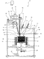
- FIG. 1 is a schematic view of a single crystal manufacturing apparatus according to an embodiment of the present invention.
- FIG. 2 is a schematic view of a single crystal production apparatus according to another embodiment of the present invention.
- FIG. 3 is a schematic view of a boat-type granular raw material melting vessel in one embodiment of the present invention.
- FIG. 4 is a schematic view of a granular raw material melting vessel having a double structure (an umbrella structure) according to another embodiment of the present invention.
- FIG. 5 is a schematic view of a simplified granular raw material melting vessel according to another embodiment of the present invention.
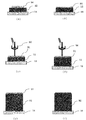
- FIG. 6 is a process diagram for producing a single crystal using the single crystal production apparatus of the present invention.
- the single crystal production apparatus and the single crystal production method of the present invention are for producing a large single crystal having a diameter exceeding 100 to 300 mm, for example, with high efficiency while homogenizing to an optimum composition.
- seed single crystal refers to the initial form of a crystal when a large-diameter single crystal is produced using a single crystal production apparatus. Those grown from this seed single crystal and maintaining the same orientation throughout are referred to as “single crystal”. On the other hand, although each is a single crystal, a collection of those having different orientations is called “polycrystal”.
- the crystal orientation is misaligned at the boundary between individual single crystals, resulting in inconveniences such as deterioration of power generation efficiency. Therefore, as a high-performance silicon substrate, it is desirable that the whole be a single crystal having the same orientation and not including such a grain boundary.
- granular raw material is a raw material that is the source of a single crystal to be produced, which is powdered (granulated).
- the “granular material” includes a granular crystal matrix and a granular additive.
- the concentration of the additive in the crystal does not match the composition of the melt from which the crystal (solid) at this concentration is deposited.
- the ratio of the concentration in this solution to the concentration of additives in the solid precipitated from this solution is called the “partition coefficient”.
- the solution in this case is called a “solvent” in the crystal growth science.
- the single crystal manufacturing apparatus 10 of the present embodiment assumes a case where a silicon single crystal having an optimal additive composition is manufactured.
- the single crystal manufacturing apparatus 10 has a single crystal holding table 18, a holding table rotating mechanism 20, and an elevating means at the bottom of the single crystal manufacturing chamber 11 that can evacuate the inside and maintain an inert gas atmosphere such as argon gas. 22, and the seed single crystal 12 having a substantially circular cross-sectional shape is arranged on the single crystal holding table 18.
- an auxiliary heating device 86 for heating the seed single crystal 12 disposed on the single crystal holding table 18 is provided outside the single crystal holding table 18, and a heat insulating material 87 is provided outside the auxiliary heating device 86. Is arranged.
- the single crystal manufacturing chamber 11 has a water cooling structure, and can efficiently adjust the internal atmosphere.
- a hopper 33 for storing the granular raw material 52 is disposed above the single crystal manufacturing chamber 11.
- the hopper 33 has an opening on the lower side, and a spiral rod (not shown) covered with polypropylene with a rotation mechanism is disposed therein, and is always rotated during use. By the rotation of the spiral rod, it is possible to suppress the occurrence of a so-called cavitation phenomenon in which cavities are generated in the granular raw material 52 in the hopper 33 and stable supply cannot be performed.
- the lower opening of the hopper 33 is directly connected to the single crystal manufacturing chamber 11 so that the inside of the hopper 33 and the single crystal manufacturing chamber 11 are always in the same atmosphere.
- a granular raw material scraping device (hereinafter also simply referred to as a scraping device) 48 is provided on the side of the opening of the hopper 33.
- the scraping device 48 has a stick-like container attached with propylene at the tip of the stick. The stick is inserted into the opening of the hopper 33 and the granular raw material 52 is placed on the container and pulled out. By rotating the rod halfway, the granular raw material 52 in the container can be supplied onto a granular raw material quantitative supply device (hereinafter also simply referred to as a quantitative supply device) 50 located below the hopper 33.
- Quantitative supply device 50 adjusts a predetermined supply amount while measuring the weight of granular raw material 52, and supplies the predetermined supply amount to supply pipe 51 with a lower supply position adjustment function.
- reference numeral 60 denotes a position adjusting mechanism.
- the hopper 33 contains a granular mixture in which additive-free granular silicon and a granular raw material to which an additive is added at a high concentration are mixed in an optimum composition.
- the composition ratio can be maintained constant.
- the hopper 33 is used alone.
- the hopper 33 is not limited to this.
- the hopper that contains the additive-free granular silicon and the hopper that contains the granular raw material to which the additive is added at a high concentration are used. And may be provided separately.
- a known attachment / detachment mechanism 46 is provided at the upper end of the hopper 33 so that a storage container 47 for storing the granular raw material 52 is detachably attached thereto.
- the attachment / detachment mechanism 46 has an atmosphere adjustment function for arbitrarily adjusting the atmosphere in the attachment / detachment mechanism 46 and the storage container 47. In FIG. 1, the container 47 is removed from the hopper 33.
- the container 47 that can be attached to and detached from the hopper 33 is used in this way, the granular raw material 52 is necessary as needed even when the single crystal manufacturing apparatus 10 is activated and a single crystal is being manufactured. Can be supplied into the hopper 33. Therefore, it is not necessary to use a large hopper 33, and the single crystal manufacturing apparatus 10 can be downsized.
- the granular raw material 52 supplied from the scraping device 48 is supplied to the granular raw material 52 through a supply pipe 51 by using a quantitative supply device 50 having a function capable of adjusting the supply amount while measuring the weight.
- a granular raw material melting vessel (hereinafter also referred to as a melting vessel) 56 of the melting means is supplied to a predetermined position.
- the supply pipe 51 is provided with a position adjustment mechanism 60 that adjusts the position of the emission port at the lower end of the supply pipe 51.
- the melting vessel 56 for melting the granular raw material 52 has a multiple structure in which a “melting part” for melting the granular raw material 52 and a “melt holding part” for holding the formed melt are divided and unmelted. It is preferable that the granular raw material 52 has a function of not being supplied downward together with the raw material melt 67.
- the melting container 56 for example, a boat-type melting container 56 as shown in FIGS. 1 and 3 and a double-structure (umbrella-shaped) melting container 56 as shown in FIGS. Is available. Further, when a silicon single crystal is manufactured, a simple melting container 56 as shown in FIG. 5 can be used.
- the boat-type melting container 56 includes a boat-like container 61 that receives the granular raw material 52 supplied from the supply pipe 51 and is mounted inside the high-frequency induction heating device 55. Inside the container 61, a separator plate 63 having a groove 66 is provided below. The separator plate 63 separates the boat-like container 61 into a “melting part” and a “melt holding part”.
- the granular raw material 52 supplied into the boat-like container 61 via the supply pipe 51 may be supplied directly into the boat-like container 61, but the granular raw material funnel 53 is used to enter the boat-like container 61. Supplying is preferable because it is easy to supply to a predetermined position.
- the temperature of the boat-like container 61 rises, the granular raw material 52 is heated and melted, and only the obtained raw material melt 67 passes next through the groove 66 below the separator 63. It moves to (right adjacent in FIG. 3) and is stored.
- the raw material melt 67 flowing out from the discharge port 68 is a tubular or rod-shaped (not shown) raw material melt extending from the lower end of the boat-like container 61 to the position directly above the seed single crystal 12 as shown in FIG. It is preferable to supply the seed single crystal 12 below through the guide means 54. As a result, the occurrence of fluctuations in the liquid level that occurs when the liquid droplets are dropped can be suppressed, and a stable liquid level can be maintained. At this time, in such a boat-type melting vessel 56, it is possible to prevent the unmelted granular raw material 52 from being supplied to the lower portion together with the raw material melt 67.
- the double-structure (umbrella-shaped) melting container 56 includes a melting dish 62 and an isolation dish 64 stacked in a cross-sectional shape on the melting dish 62.
- a melting part that melts the granular raw material 52 and a melt holding part that holds the raw material melt 67 to be formed are separated from the isolation plate 64.
- the 2nd infrared irradiation apparatuses 72 and 82 are used as shown in FIG. Infrared rays 74 and 85 are applied to the melting vessel 56.
- the second infrared irradiation devices 72 and 82 are preferably arranged on the upper side and the side of the melting vessel 56, but may be on either the upper side or the side. .
- a laser beam irradiation device it is preferable to use a laser beam irradiation device.
- a resistance heating device (particularly a carbon resistance in the case of producing a silicon single crystal).
- it may be an irradiating means configured to reflect infrared rays emitted from an infrared lamp on the inner surface of the ellipsoidal reflecting mirror, for example.
- a halogen lamp, a xenon lamp, or the like can be used as the infrared lamp.
- the granular raw material 52 is heated and melted by irradiation with infrared rays from the second infrared irradiation devices 72 and 82, and only the raw material melt 67 is provided at the lower end of the isolation tray 64. It moves to the center through the groove 66 and is stored in the isolation tray 64.
- the raw material melt 67 stored in the isolation plate 64 stays in the center and reaches the height of the discharge port 68 provided in the pipe 59 in the center. And is supplied to the upper surface of the lower seed single crystal. Thereby, it is possible to prevent the unmelted granular raw material 52 from dropping downward together with the raw material melt 67.
- the pipe 59 at the center extends to the position just above the seed single crystal 12 and serves as the raw material melt guiding means 54, thereby generating the fluctuation of the liquid level that occurs when the droplet is dropped. And a stable liquid level can be maintained.
- the simple-type melting container 56 has a cylindrical shape in which the granular raw material 52 is accommodated from the upper end portion and the lower end portion is inserted into the optimum melt 91 on the upper surface of the seed single crystal 12. It comprises a portion 57 and a funnel-like portion 58 provided inside the tubular portion 57 and having an opening at the lower end.
- the second infrared irradiation devices 72 and 82 may be used as in the case of the melting container 56 having a double structure (umbrella structure) shown in FIG.
- materials for such a boat-type melting container 56, a double-structure (umbrella-shaped) melting container 56, and a simple-type melting container 56 platinum, iridium, quartz, silicon carbide, carbon, graphite, carbon or graphite A material obtained by siliconizing the surface of the material or a material obtained by coating the surface of a carbon or graphite material with silicon carbide in advance is selected and used depending on the material.
- the double-structure (umbrella-shaped) melting vessel 56 has a function of being rotated in the horizontal direction by the melting vessel rotating mechanism 70.
- the double-structure (umbrella-shaped) melting container 56 rotates in this way, the granular raw material 52 supplied from the supply pipe 51 is uniformly supplied into the melting container 56, so that the granular raw material 52 is reliably melted. be able to.
- a seed single crystal holding table (hereinafter also simply referred to as a holding table) 18 is disposed in the lower part of the single crystal manufacturing chamber 11.
- An auxiliary heating device 86 is disposed outside the holding table 18, and the periphery of the auxiliary heating device 86 is constituted by a heat insulating material 87.
- the seed single crystal 12 is disposed on the holding table 18, and the holding table 18 is rotated at a predetermined speed by the holding table rotating mechanism 20, thereby irradiating unevenness of infrared rays (laser light) irradiated on the upper surface of the seed single crystal 12.
- the temperature of the melt phase formed can be reduced and homogenized.
- a lifting means 22 is arranged on the holding table 18. As a result, the position in the height direction of the melt phase formed on the upper surface of the seed single crystal 12 can always be controlled to the optimum position.
- infrared transmission windows 27, 73, 84 is installed between the seed single crystal 12 and the first infrared irradiation device 26 for heating the seed single crystal, and between the melting vessel 56 and the second infrared irradiation devices 72 and 82.
- the material of the infrared transmitting windows 27, 73, and 84 is not particularly limited as long as it is a material that can transmit infrared rays.
- it is preferably made of quartz.
- the single crystal manufacturing apparatus 10 is configured as described above, and in particular, a boat-type melting container 56, a double-structure (umbrella-shaped structure) melting container 56, and a simple-type melting container 56.
- the melting vessel 56 With the melting vessel 56, the granular raw material 52 is used as the raw material melt 67, and only the raw material melt 67 is supplied to the upper surface of the seed single crystal 12, thereby eliminating negative crystals and grain boundaries. It is a high-quality large single crystal, and it is possible to produce a high-quality single crystal whose composition is homogeneous at the optimum additive concentration in both the vertical and horizontal directions.
- this single crystal manufacturing apparatus 10 does not use a crucible, there is no contamination from the crucible, and, for example, in the case of silicon, there is no generation of a melted lamella, which is one of the most serious defects. Crystals can be produced.
- the granular raw material pellet 90 for optimum melt prepared by predicting the composition and amount of the optimum melt phase to be formed on the upper surface of the seed single crystal 12 is arranged.
- the single crystal manufacturing chamber 11 is sealed, the atmosphere inside the single crystal manufacturing chamber 11 is evacuated by an exhaust unit (not shown), and an inert atmospheric gas such as argon gas is introduced into the single crystal manufacturing chamber 11.
- an inert atmospheric gas such as argon gas is introduced into the single crystal manufacturing chamber 11.
- the upper surface of the seed single crystal 12 is irradiated with infrared rays 28 from the first infrared irradiation device 26 to form an optimum melt phase composed of the optimum melt 91.
- the scraping device 48, the quantitative supply device 50, and the container heating device located above the seed single crystal 12 are actuated to scrape the granular raw material 52 having the optimum composition in the hopper 33.
- the raw material melt 67 is supplied from the supply pipe 51 into the melting vessel 56 at a predetermined supply speed, and the resulting raw material melt 67 is supplied into the optimum melt 91 on the upper surface of the seed single crystal 12.
- the temperature is gradually lowered and cooled to room temperature, the single crystal manufacturing chamber 11 is opened, and the single crystal 92 on the holding table 18 is taken out as a product.
- the dose distribution of the infrared rays 28 is devised so that the surface shape of the single crystal 92 is kept as flat as possible throughout the entire manufacturing process.
- a granular raw material in which a granular raw material 52 composed of a granular crystal base material (granular silicon) and a granular additive material is mixed in an optimal composition is used.
- the mixed granular material 52 having the optimum composition is stored in the hopper 33, and the granular material 52 is dropped from the supply pipe 51 into the melting container 56 using the scraping device 48 and the fixed amount supply device 50.
- the supply of the granular raw material 52, melting, and solidification as the single crystal 92 are continuously performed.
- the granular raw material 52 is continuously supplied into the melting vessel 56, heated and melted to obtain the raw material melt 67, which is supplied to the upper surface of the seed single crystal 12 to precipitate the single crystal 92. Therefore, the composition of the obtained single crystal 92 is the same as the composition of the granular raw material 52 having the optimum composition.
- the composition in the produced crystal can be homogenized with the optimum composition.
- This makes it possible to produce a high-quality single crystal with a homogeneous composition at an additive concentration that can achieve high conversion efficiency when used in, for example, photovoltaic power generation, and can produce a single crystal with an optimum composition with a high yield, and thus It can contribute to the cost reduction of manufacturing cost.
- the single crystal manufacturing apparatus 10 of the present invention and the single crystal manufacturing method using the single crystal manufacturing apparatus 10 have been described above, but the present invention is not limited to the above embodiment.
- a mixed granular raw material obtained by mixing an additive-free high-purity silicon granular raw material and a granular raw material to which phosphorus is added at a high concentration so as to have a predetermined optimum composition is used. I use it.
- a mixed granular raw material obtained by mixing an additive-free high-purity silicon granular raw material and a granular raw material added with boron at a high concentration to have a predetermined optimum composition is used. Yes.
- the particle size of the granular raw material 52 or the like is not particularly mentioned, but if the granular raw material 52 is too large, it may take time to melt. Conversely, if it is too small, inconveniences such as scattering during supply tend to occur.
- the diameter of the particles of the granular raw material 52 is preferably about 0.1 to 0.5 mm.
- the case where the granular raw material 52 of high-purity additive-free silicon is used as the granular crystal base material has been described as an example.
- the present invention is not limited to this and is prepared according to the substance to be manufactured.
- a granular raw material 52 can be used.
- a plurality of first infrared irradiation devices 26 that perform infrared irradiation may be provided, but a plurality of scraping devices, quantitative supply devices, supply pipes, melting containers, and container heating devices may be provided. It is.
- the scraping device, quantitative supply device, supply tube, melting container, and container heating device are preferably provided in a single set.
- the single crystal manufacturing apparatus 10 of the present invention can be variously modified without departing from the object of the present invention.
Landscapes
- Chemical & Material Sciences (AREA)
- Engineering & Computer Science (AREA)
- Crystallography & Structural Chemistry (AREA)
- Materials Engineering (AREA)
- Metallurgy (AREA)
- Organic Chemistry (AREA)
- Crystals, And After-Treatments Of Crystals (AREA)
Abstract
Cette invention a pour objet la fabrication d'un monocristal de haute qualité qui est un monocristal de grande qualité exempt de limites de grains cristallins et a des compositions avec des concentrations optimales en additifs qui sont uniformes à la fois dans la direction verticale et dans la direction horizontale. Un dispositif de fabrication de monocristal selon l'invention comprend au moins : des moyens d'alimentation en matière première granulaire pour distribuer vers le bas une certaine quantité de matière première granulaire ; des moyens de fusion de matière première granulaire pour distribuer vers le bas un liquide fondu de matière première qui est obtenu par chauffage et fusion de la matière première granulaire distribuée par les moyens d'alimentation en matière première granulaire ; et des moyens de cristallisation pour précipiter un monocristal à partir d'un liquide fondu mixte formé par la réception d'un liquide fondu, formé par irradiation de la surface supérieure d'un germe de monocristal avec une lumière infrarouge provenant d'un premier dispositif d'émission de lumière infrarouge, et du liquide fondu de matière première distribué à partir des moyens de fusion de matière première granulaire.
Priority Applications (5)
| Application Number | Priority Date | Filing Date | Title |
|---|---|---|---|
| PCT/JP2018/013162 WO2019186870A1 (fr) | 2018-03-29 | 2018-03-29 | Dispositif de fabrication d'un monocristal et procédé de fabrication d'un monocristal |
| EP18785794.1A EP3572559B1 (fr) | 2018-03-29 | 2018-03-29 | Dispositif de fabrication d'un monocristal |
| US16/303,254 US20210222318A1 (en) | 2018-03-29 | 2018-03-29 | Single-Crystal Production Equipment and Single-Crystal Production Method |
| CN201880001867.5A CN110546314B (zh) | 2018-03-29 | 2018-03-29 | 单晶制造装置 |
| JP2018537687A JP6607651B1 (ja) | 2018-03-29 | 2018-03-29 | 単結晶製造装置 |
Applications Claiming Priority (1)
| Application Number | Priority Date | Filing Date | Title |
|---|---|---|---|
| PCT/JP2018/013162 WO2019186870A1 (fr) | 2018-03-29 | 2018-03-29 | Dispositif de fabrication d'un monocristal et procédé de fabrication d'un monocristal |
Publications (1)
| Publication Number | Publication Date |
|---|---|
| WO2019186870A1 true WO2019186870A1 (fr) | 2019-10-03 |
Family
ID=68057984
Family Applications (1)
| Application Number | Title | Priority Date | Filing Date |
|---|---|---|---|
| PCT/JP2018/013162 Ceased WO2019186870A1 (fr) | 2018-03-29 | 2018-03-29 | Dispositif de fabrication d'un monocristal et procédé de fabrication d'un monocristal |
Country Status (5)
| Country | Link |
|---|---|
| US (1) | US20210222318A1 (fr) |
| EP (1) | EP3572559B1 (fr) |
| JP (1) | JP6607651B1 (fr) |
| CN (1) | CN110546314B (fr) |
| WO (1) | WO2019186870A1 (fr) |
Families Citing this family (1)
| Publication number | Priority date | Publication date | Assignee | Title |
|---|---|---|---|---|
| JP7633637B2 (ja) | 2020-07-28 | 2025-02-20 | 株式会社ノベルクリスタルテクノロジー | 単結晶製造装置及び単結晶の製造方法 |
Citations (6)
| Publication number | Priority date | Publication date | Assignee | Title |
|---|---|---|---|---|
| JPH10273374A (ja) * | 1997-03-27 | 1998-10-13 | Kawasaki Steel Corp | シリコンの精製方法 |
| JPH11274537A (ja) * | 1998-03-24 | 1999-10-08 | Tokyo Denshi Yakin Kenkyusho:Kk | 大粒径多結晶シリコンの製造法 |
| JPH11292682A (ja) * | 1998-04-02 | 1999-10-26 | Shin Etsu Handotai Co Ltd | シリコン単結晶の製造方法および製造装置 |
| JP5279727B2 (ja) | 2007-12-25 | 2013-09-04 | 株式会社クリスタルシステム | 浮遊帯域溶融装置 |
| JP2014114149A (ja) * | 2012-12-12 | 2014-06-26 | Sanko Kikai Kk | 粒状原料供給装置 |
| WO2018003386A1 (fr) * | 2016-06-29 | 2018-01-04 | 株式会社クリスタルシステム | Appareil de production d'un monocristal et procédé de production d'un monocristal |
Family Cites Families (8)
| Publication number | Priority date | Publication date | Assignee | Title |
|---|---|---|---|---|
| JPH06100394A (ja) * | 1992-09-17 | 1994-04-12 | Nkk Corp | 単結晶製造用原料供給方法及び装置 |
| CN1224735C (zh) * | 1998-05-29 | 2005-10-26 | 东洋通信机株式会社 | 单晶制造装置、单晶制造方法及单晶体 |
| CN1330798C (zh) * | 2004-05-31 | 2007-08-08 | 南开大学 | 熔体注入法生长近化学比铌酸锂晶体系统及其工艺 |
| JP4317575B2 (ja) * | 2005-08-19 | 2009-08-19 | Sumcoソーラー株式会社 | シリコン電磁鋳造装置およびその操作方法 |
| JP4307516B1 (ja) * | 2008-11-25 | 2009-08-05 | 佑吉 堀岡 | 結晶成長装置及び結晶成長方法 |
| RU2418109C1 (ru) * | 2009-11-09 | 2011-05-10 | Инновационно-технический центр Общество с ограниченной ответственностью "СИТИС" | Установка для получения монокристаллов |
| CN104328483A (zh) * | 2014-11-13 | 2015-02-04 | 吴晟 | 一种单晶生长方法及装置 |
| US20190032242A1 (en) * | 2016-07-28 | 2019-01-31 | Crystal Systems Corporation | Single-Crystal Production Equipment |
-
2018
- 2018-03-29 WO PCT/JP2018/013162 patent/WO2019186870A1/fr not_active Ceased
- 2018-03-29 US US16/303,254 patent/US20210222318A1/en not_active Abandoned
- 2018-03-29 EP EP18785794.1A patent/EP3572559B1/fr active Active
- 2018-03-29 CN CN201880001867.5A patent/CN110546314B/zh active Active
- 2018-03-29 JP JP2018537687A patent/JP6607651B1/ja active Active
Patent Citations (6)
| Publication number | Priority date | Publication date | Assignee | Title |
|---|---|---|---|---|
| JPH10273374A (ja) * | 1997-03-27 | 1998-10-13 | Kawasaki Steel Corp | シリコンの精製方法 |
| JPH11274537A (ja) * | 1998-03-24 | 1999-10-08 | Tokyo Denshi Yakin Kenkyusho:Kk | 大粒径多結晶シリコンの製造法 |
| JPH11292682A (ja) * | 1998-04-02 | 1999-10-26 | Shin Etsu Handotai Co Ltd | シリコン単結晶の製造方法および製造装置 |
| JP5279727B2 (ja) | 2007-12-25 | 2013-09-04 | 株式会社クリスタルシステム | 浮遊帯域溶融装置 |
| JP2014114149A (ja) * | 2012-12-12 | 2014-06-26 | Sanko Kikai Kk | 粒状原料供給装置 |
| WO2018003386A1 (fr) * | 2016-06-29 | 2018-01-04 | 株式会社クリスタルシステム | Appareil de production d'un monocristal et procédé de production d'un monocristal |
Non-Patent Citations (1)
| Title |
|---|
| See also references of EP3572559A4 |
Also Published As
| Publication number | Publication date |
|---|---|
| CN110546314A (zh) | 2019-12-06 |
| US20210222318A1 (en) | 2021-07-22 |
| EP3572559A4 (fr) | 2020-01-22 |
| JP6607651B1 (ja) | 2019-11-20 |
| JPWO2019186870A1 (ja) | 2020-04-30 |
| EP3572559A1 (fr) | 2019-11-27 |
| EP3572559B1 (fr) | 2024-09-25 |
| CN110546314B (zh) | 2021-04-02 |
Similar Documents
| Publication | Publication Date | Title |
|---|---|---|
| CN107849732B (zh) | 单晶制造装置和单晶制造方法 | |
| US20210222320A1 (en) | Method of Producing a Single-Crystal | |
| JP2020063163A (ja) | 単結晶製造装置 | |
| TW201109483A (en) | Systems, methods and substrates of monocrystalline germanium crystal growth | |
| JP6607651B1 (ja) | 単結晶製造装置 | |
| JP6607652B1 (ja) | 単結晶製造装置 | |
| JP6708173B2 (ja) | リチャージ管及び単結晶の製造方法 | |
| JPH06100394A (ja) | 単結晶製造用原料供給方法及び装置 | |
| CN118407112A (zh) | 垂直布里奇曼法制备的大体积铯铅溴单晶及其制备方法和应用 | |
| US20070020872A1 (en) | Process and apparatus for producing single crystal | |
| JP2015020942A (ja) | 結晶成長装置および結晶成長方法 | |
| JP4788444B2 (ja) | シリコン単結晶の製造方法 | |
| JP2004203721A (ja) | 単結晶成長装置および成長方法 | |
| JP6627737B2 (ja) | 単結晶引上げ装置 | |
| CN1125199C (zh) | 单晶制造方法及单晶制造装置 | |
| EP1772538A1 (fr) | Procédé et dispositif pour la fabrication de monocristaux | |
| JP2005343736A (ja) | 単結晶製造方法とその装置 | |
| JPH08183688A (ja) | 連続引上法による結晶の製造方法及び製造装置 | |
| JPH07138090A (ja) | 混晶の液相成長方法及び装置 |
Legal Events
| Date | Code | Title | Description |
|---|---|---|---|
| ENP | Entry into the national phase |
Ref document number: 2018537687 Country of ref document: JP Kind code of ref document: A |
|
| ENP | Entry into the national phase |
Ref document number: 2018785794 Country of ref document: EP Effective date: 20181024 |
|
| ENP | Entry into the national phase |
Ref document number: 2018785794 Country of ref document: EP Effective date: 20181024 |
|
| NENP | Non-entry into the national phase |
Ref country code: DE |