EP3582955B1 - Verfahren zur herstellung eines gegenstands mittels eines additiven fertigungsverfahrens unter einsatz eines polycarbonat-aufbaumaterials mit verbesserter fliessfähigkeit - Google Patents
Verfahren zur herstellung eines gegenstands mittels eines additiven fertigungsverfahrens unter einsatz eines polycarbonat-aufbaumaterials mit verbesserter fliessfähigkeit Download PDFInfo
- Publication number
- EP3582955B1 EP3582955B1 EP18703795.7A EP18703795A EP3582955B1 EP 3582955 B1 EP3582955 B1 EP 3582955B1 EP 18703795 A EP18703795 A EP 18703795A EP 3582955 B1 EP3582955 B1 EP 3582955B1
- Authority
- EP
- European Patent Office
- Prior art keywords
- weight
- construction material
- eta
- pas
- glass fibers
- Prior art date
- Legal status (The legal status is an assumption and is not a legal conclusion. Google has not performed a legal analysis and makes no representation as to the accuracy of the status listed.)
- Active
Links
Classifications
-
- C—CHEMISTRY; METALLURGY
- C08—ORGANIC MACROMOLECULAR COMPOUNDS; THEIR PREPARATION OR CHEMICAL WORKING-UP; COMPOSITIONS BASED THEREON
- C08L—COMPOSITIONS OF MACROMOLECULAR COMPOUNDS
- C08L69/00—Compositions of polycarbonates; Compositions of derivatives of polycarbonates
-
- B—PERFORMING OPERATIONS; TRANSPORTING
- B29—WORKING OF PLASTICS; WORKING OF SUBSTANCES IN A PLASTIC STATE IN GENERAL
- B29C—SHAPING OR JOINING OF PLASTICS; SHAPING OF MATERIAL IN A PLASTIC STATE, NOT OTHERWISE PROVIDED FOR; AFTER-TREATMENT OF THE SHAPED PRODUCTS, e.g. REPAIRING
- B29C64/00—Additive manufacturing, i.e. manufacturing of three-dimensional [3D] objects by additive deposition, additive agglomeration or additive layering, e.g. by 3D printing, stereolithography or selective laser sintering
- B29C64/10—Processes of additive manufacturing
- B29C64/106—Processes of additive manufacturing using only liquids or viscous materials, e.g. depositing a continuous bead of viscous material
-
- B—PERFORMING OPERATIONS; TRANSPORTING
- B29—WORKING OF PLASTICS; WORKING OF SUBSTANCES IN A PLASTIC STATE IN GENERAL
- B29C—SHAPING OR JOINING OF PLASTICS; SHAPING OF MATERIAL IN A PLASTIC STATE, NOT OTHERWISE PROVIDED FOR; AFTER-TREATMENT OF THE SHAPED PRODUCTS, e.g. REPAIRING
- B29C64/00—Additive manufacturing, i.e. manufacturing of three-dimensional [3D] objects by additive deposition, additive agglomeration or additive layering, e.g. by 3D printing, stereolithography or selective laser sintering
- B29C64/10—Processes of additive manufacturing
- B29C64/106—Processes of additive manufacturing using only liquids or viscous materials, e.g. depositing a continuous bead of viscous material
- B29C64/118—Processes of additive manufacturing using only liquids or viscous materials, e.g. depositing a continuous bead of viscous material using filamentary material being melted, e.g. fused deposition modelling [FDM]
-
- B—PERFORMING OPERATIONS; TRANSPORTING
- B29—WORKING OF PLASTICS; WORKING OF SUBSTANCES IN A PLASTIC STATE IN GENERAL
- B29C—SHAPING OR JOINING OF PLASTICS; SHAPING OF MATERIAL IN A PLASTIC STATE, NOT OTHERWISE PROVIDED FOR; AFTER-TREATMENT OF THE SHAPED PRODUCTS, e.g. REPAIRING
- B29C64/00—Additive manufacturing, i.e. manufacturing of three-dimensional [3D] objects by additive deposition, additive agglomeration or additive layering, e.g. by 3D printing, stereolithography or selective laser sintering
- B29C64/10—Processes of additive manufacturing
- B29C64/165—Processes of additive manufacturing using a combination of solid and fluid materials, e.g. a powder selectively bound by a liquid binder, catalyst, inhibitor or energy absorber
-
- B—PERFORMING OPERATIONS; TRANSPORTING
- B33—ADDITIVE MANUFACTURING TECHNOLOGY
- B33Y—ADDITIVE MANUFACTURING, i.e. MANUFACTURING OF THREE-DIMENSIONAL [3D] OBJECTS BY ADDITIVE DEPOSITION, ADDITIVE AGGLOMERATION OR ADDITIVE LAYERING, e.g. BY 3D PRINTING, STEREOLITHOGRAPHY OR SELECTIVE LASER SINTERING
- B33Y70/00—Materials specially adapted for additive manufacturing
- B33Y70/10—Composites of different types of material, e.g. mixtures of ceramics and polymers or mixtures of metals and biomaterials
-
- C—CHEMISTRY; METALLURGY
- C08—ORGANIC MACROMOLECULAR COMPOUNDS; THEIR PREPARATION OR CHEMICAL WORKING-UP; COMPOSITIONS BASED THEREON
- C08K—Use of inorganic or non-macromolecular organic substances as compounding ingredients
- C08K5/00—Use of organic ingredients
- C08K5/04—Oxygen-containing compounds
- C08K5/10—Esters; Ether-esters
- C08K5/101—Esters; Ether-esters of monocarboxylic acids
- C08K5/103—Esters; Ether-esters of monocarboxylic acids with polyalcohols
-
- B—PERFORMING OPERATIONS; TRANSPORTING
- B33—ADDITIVE MANUFACTURING TECHNOLOGY
- B33Y—ADDITIVE MANUFACTURING, i.e. MANUFACTURING OF THREE-DIMENSIONAL [3D] OBJECTS BY ADDITIVE DEPOSITION, ADDITIVE AGGLOMERATION OR ADDITIVE LAYERING, e.g. BY 3D PRINTING, STEREOLITHOGRAPHY OR SELECTIVE LASER SINTERING
- B33Y10/00—Processes of additive manufacturing
-
- B—PERFORMING OPERATIONS; TRANSPORTING
- B33—ADDITIVE MANUFACTURING TECHNOLOGY
- B33Y—ADDITIVE MANUFACTURING, i.e. MANUFACTURING OF THREE-DIMENSIONAL [3D] OBJECTS BY ADDITIVE DEPOSITION, ADDITIVE AGGLOMERATION OR ADDITIVE LAYERING, e.g. BY 3D PRINTING, STEREOLITHOGRAPHY OR SELECTIVE LASER SINTERING
- B33Y70/00—Materials specially adapted for additive manufacturing
-
- B—PERFORMING OPERATIONS; TRANSPORTING
- B33—ADDITIVE MANUFACTURING TECHNOLOGY
- B33Y—ADDITIVE MANUFACTURING, i.e. MANUFACTURING OF THREE-DIMENSIONAL [3D] OBJECTS BY ADDITIVE DEPOSITION, ADDITIVE AGGLOMERATION OR ADDITIVE LAYERING, e.g. BY 3D PRINTING, STEREOLITHOGRAPHY OR SELECTIVE LASER SINTERING
- B33Y80/00—Products made by additive manufacturing
Definitions
- the present invention relates to a method for producing an object by means of an additive manufacturing method from a building material, the building material comprising a polycarbonate with improved flowability. It also relates to the use of a polycarbonate with improved flowability as a building material in an additive melt layering process.
- WO 2015/077053 A1 a reduced density article comprising a thermoplastic polycarbonate composition.
- the article has a density (ASTM D792-00) of 80% to 99%, based on the weight of a similar solid injection molded body without voids.
- the article has a microstructure, as determined by optical microscopy, with 1% by volume to 20% by volume of voids, at least 80% of the voids being those with a large ratio of length to width and less than 20% of the voids being spherical Are cavities with a diameter between 10 and 100 micrometers.
- the thermoplastic polycarbonate composition comprises at least 50 mol% bisphenol A and has a weight average molecular weight (M w ) of 10,000 to 50,000, a glass transition temperature Tg of 130 ° C. to 180 ° C., a content of phenolic OH groups of less than 50 ppm, a halogen group content of less than 100 ppm and a diaryl carbonate content of less than 1% by weight.
- M w weight average molecular weight
- WO 2015/195527 A1 relates to a method of making a thermoplastic article in which a plurality of layers of thermoplastic material are laid down in a predetermined pattern to form the article.
- the thermoplastic material comprises a thermoplastic composition having a melt flow index of 30 grams / 10 minutes to 75 grams / 10 minutes according to ASTM D1238-04 at either 230 ° C and 3.8 kg or at 300 ° C and 1.2 kg.
- the thermoplastic material can be a polycarbonate homopolymer, a polycarbonate copolymer, a polyester, or a combination thereof.
- WO 2015/193818 A1 discloses a method of making an article in which one or more layers of an extruded material are deposited in the molten state in a predetermined pattern, at least one of the layers being formed from a build material.
- the building material is exposed to an effective dose of ultraviolet radiation to cause crosslinking within the article.
- the building material here is a polymeric composition which is crosslinkable Contains polycarbonate resin having a photoactive group derived from a benzophenone.
- Polycarbonates are polymers with a comparatively high glass transition temperature. The processing parameters and formulations for polycarbonates must take this into account.
- extrusion types are optimized to remain as dimensionally stable as possible after exiting an extrusion nozzle.
- injection molding types should have greater flowability in order to be able to reproduce all structures of the molding tool.
- WO 2016/087296 A1 WO 2017/005735 A1 and WO 2017/005739 A1 in this context relate to the use of diglycerol esters as flow aids in polycarbonate melts.
- WO 2016/087296 A1 for example a composition containing: A) 20% by weight to 99.0% by weight aromatic polycarbonate; B) 0.0 to 1.0% by weight of at least one flame retardant; C) 0.5% by weight to 50.0% by weight of at least one glass fiber, one carbon fiber and / or carbon nanotubes; D) 0.01% by weight to 3.0% by weight of at least one flow aid selected from the group of diglycerol esters; E) 0.0% by weight to 5.0% by weight of at least one anti-drip agent; F) 0.0% by weight to 1.0% by weight of at least one thermal stabilizer and G) 0.0% by weight to 10.0% by weight of further additives.
- the present invention has the object of specifying an additive manufacturing method with which in particular filled and / or high molecular weight polycarbonate-based construction materials can be processed with improved flowability.
- the building material comprises polycarbonate and a flow aid selected from the group of diglycerol esters.
- a flow aid selected from the group of diglycerol esters.
- the object to be manufactured can in itself serve as the goal of the manufacturing process. However, it is also possible that the object to be produced is part of a larger assembly and its production represents a partial step in the production of the assembly.
- the object is manufactured from a construction material by means of an additive manufacturing process (“3D printing”).
- the additive manufacturing process is a melt layering process (Fused Filament Fabrication, FFF or Fused Deposition Modeling, FDM). If the number of repetitions for the application is sufficiently small, one can also speak of a two-dimensional object that is to be built up.
- Such a two-dimensional object can also be characterized as a coating.
- ⁇ 1 to ⁇ 20 repetitions for the application can be carried out to build it up.
- the individual filaments which are applied can have a diameter of 30 ⁇ m to 2000 ⁇ m, preferably 40 ⁇ m to 1000 ⁇ m and particularly preferably 50 ⁇ m to 500 ⁇ m.
- the first step of the process involves building up the first layer on a carrier.
- the second step is then carried out in which further layers are applied to previously applied layers of the building material until the desired end result is obtained in the form of the object.
- the at least partially melted building material connects to already existing layers of the material in order to build up a structure in the z-direction.
- a body is usually built up by repeating a work level being followed line by line (formation of a layer) and then the working level is shifted upwards in a "stacking" manner (formation of at least one further layer on the first layer) so that a shape is created in layers.
- the outlet temperature of the mixtures of substances from the nozzle can be 80 ° C to 420 ° C, for example. It is also possible to heat the substrate table and / or any installation space that may be present, for example to 20 ° C to 250 ° C. This can prevent the applied layer from cooling too quickly, so that a further layer applied thereon sufficiently bonds with the first layer.
- the build-up material preferably contains no further components, but components A) to G) add up to 100% by weight.
- the construction material may for example a melt volume-flow rate MVR of 1 to 100 cm 3/10 min, more preferably from 2 to 85 and particularly preferably from 3 to 75 cm 3/10 min, determined according to ISO 1133 (test temperature 300 ° C, mass 1.2 kg), determined according to ISO 1133 (test temperature 300 ° C., mass 1.2 kg), and in the case of glass fibers contained in the compositions, a Charpy impact strength, determined according to DIN EN ISO 179 at room temperature, of greater than 35 kJ / m 2 , exhibit.
- MVR melt volume-flow rate
- the molecular weights Mw of the build-up material are between 10,000 g / mol and 50,000 g / mol, preferably between 12,000 g / mol and 40,000 g / mol and particularly preferably between 15,000 g / mol and 38,000 g / mol (determined by GPC with a BPA polycarbonate Calibration).
- Polycarbonates in the context of the present invention are both homopolycarbonates and copolycarbonates; the polycarbonates can be linear or branched in a known manner. Mixtures of polycarbonates can also be used according to the invention.
- the polycarbonates are produced in a known manner from diphenols, carbonic acid derivatives, optionally chain terminators and branching agents.
- aromatic polycarbonates takes place e.g. by reacting diphenols with carbonic acid halides, preferably phosgene, and / or with aromatic dicarboxylic acid dihalides, preferably benzenedicarboxylic acid dihalides, according to the interfacial process, optionally using chain terminators and optionally using trifunctional or more than trifunctional branching agents. Production via a melt polymerization process by reacting diphenols with diphenyl carbonate, for example, is also possible.
- Diphenols suitable for the production of the polycarbonates are, for example, hydroquinone, resorcinol, dihydroxydiphenyls, bis (hydroxyphenyl) alkanes, bis (hydroxyphenyl) cycloalkanes, bis (hydroxyphenyl) sulfides, bis (hydroxyphenyl) ethers, bis ( hydroxyphenyl) ketones, bis (hydroxyphenyl) sulfones, bis (hydroxyphenyl) sulfoxides, ⁇ - ⁇ '-bis (hydroxyphenyl) diisopropylbenzenes, phthalimidines derived from isatin or phenolphthalein derivatives and their nucleus alkylated, nucleus arylated and nucleus halogenated compounds.
- Preferred diphenols are 4,4'-dihydroxydiphenyl, 2,2-bis (4-hydroxyphenyl) propane (bisphenol A), 2,4-bis (4-hydroxyphenyl) -2-methylbutane, 1,1-bis (4-hydroxyphenyl) -p-diisopropylbenzene, 2,2-bis- (3-methyl-4-hydroxyphenyl) -propane, dimethyl-bisphenol A, bis- (3,5-dimethyl-4-hydroxyphenyl) -methane, 2 , 2-bis- (3,5-dimethyl-4-hydroxyphenyl) -propane, bis- (3,5-dimethyl-4-hydroxyphenyl) -sulfone, 2,4-bis- (3,5-dimethyl-4- hydroxyphenyl) -2-methylbutane, 1,1-bis (3,5-dimethyl-4-hydroxyphenyl) -p-diisopropylbenzene and 1,1-bis- (4-hydroxyphenyl) -3,3,
- diphenols are 2,2-bis (4-hydroxyphenyl) propane (bisphenol A), 2,2-bis (3,5-dimethyl-4-hydroxyphenyl) propane, 1,1-bis (4th -hydroxyphenyl) -cyclohexane, 1,1-bis- (4-hydroxyphenyl) -3,3,5-trimethylcyclohexane and dimethyl-bisphenol A.
- diphenols are for example in US-A-3,028,635 , US-A 2,999,825 , US-A 3,148,172 , US-A-2,991,273 , US-A 3,271,367 , US-A 4,982,014 and US-A 2 999 846 , in DE-A 1 570 703 , DE-A 2063 050 , DE-A 2 036 052 , DE-A 2 211 956 and DE-A 3 832 396 , in FR-A 1 561 518 , in the monograph " H. Schnell, Chemistry and Physics of Polycarbonates, Interscience Publishers, New York 1964 " as in JP-A 62039/1986 , JP-A 62040/1986 and JP-A 105550/1986 described.
- Suitable carbonic acid derivatives are, for example, phosgene or diphenyl carbonate.
- Suitable chain terminators which can be used in the production of the polycarbonates are monophenols.
- Suitable monophenols are, for example, phenol itself, alkylphenols such as cresols, p-tert-butylphenol, cumylphenol, and mixtures thereof.
- Preferred chain terminators are the phenols which are mono- or polysubstituted by C 1 - to C 30 -alkyl radicals, linear or branched, preferably unsubstituted, or substituted by tert-butyl. Particularly preferred chain terminators are phenol, cumylphenol and / or p-tert-butylphenol.
- the amount of chain terminator to be used is preferably 0.1 to 5 mol%, based on the moles of diphenols used in each case.
- the chain terminators can be added before, during or after the reaction with a carbonic acid derivative.
- Suitable branching agents are the trifunctional or more than trifunctional compounds known in polycarbonate chemistry, in particular those with three or more than three phenolic OH groups.
- Suitable branching agents are, for example, 1,3,5-tri- (4-1, hydroxyphenyl) -benzene, 1,1,1-tri- (4-hydroxyphenyl) -ethane, tri- (4-hydroxyphenyl) -phenylmethane, 2, 4-bis- (4-hydroxyphenylisopropyl) -phenol, 2,6-bis- (2-hydroxy-5'-methyl-benzyl) -4-methylphenol, 2- (4-hydroxyphenyl) -2- (2,4- dihydroxyphenyl) propane, tetra (4-hydroxyphenyl) methane, tetra (4- (4-hydroxyphenylisopropyl) phenoxy) methane and 1,4-bis ((4 ', 4 "-dihydroxytriphenyl) methyl) benzene and 3,3-bis (3-methyl-4-hydroxyphenyl) -2-oxo-2,3-dihydroindole.
- the amount of branching agents to be optionally used is preferably 0.05 mol% to 2.00 mol%, based on the moles of the diphenols used in each case.
- the branching agents can either be initially introduced with the diphenols and the chain terminators in the aqueous alkaline phase or dissolved in an organic solvent and added before the phosgenation. In the case of the transesterification process, the branching agents are used together with the diphenols.
- Particularly preferred polycarbonates are the homopolycarbonate based on bisphenol A, the homopolycarbonate based on 1,3-bis- (4-hydroxyphenyl) -3,3,5-trimethylcyclohexane and the copolycarbonates based on the two monomers bisphenol A and 1,1 -Bis- (4-hydroxyphenyl) -3,3,5 -trimethylcyclohexane.
- component A is preferably used in the form of powders, granules or mixtures of powders and granules.
- a mixture of the aromatic polycarbonates A1 and A2 is preferably used with the following properties:
- the amount of aromatic polycarbonate A1 is, based on the total amount of polycarbonate, 25.0 to 85.0% by weight, preferably 28.0 to 84.0% by weight, particularly preferably 30.0 to 83.0% by weight .-%, wherein said aromatic polycarbonate based on bisphenol a with a preferred melt volume-flow rate MVR 7 to 15 cm 3/10 min, more preferably having a melt volume-flow rate MVR 8-12 cm 3/10 min and most preferably with a melt volume-flow rate MVR 8-11 cm 3/10 min, determined according to ISO 1133 (test temperature 300 ° C, mass 1.2 kg) is.
- the amount of the powdery aromatic polycarbonate A2, based on the total amount of polycarbonate, is 3.0 to 12.0% by weight, preferably 4.0 to 11.0% by weight, particularly preferably 3.0 to 10.0 wt .-%, wherein said aromatic polycarbonate preferably based on bisphenol a having a preferred melt volume-flow rate MVR of 3 to 8 cm 3/10 min, more preferably having a melt volume-flow rate MVR 4-7 cm 3/10 min, and more preferably with a melt volume flow rate MVR of 6 cm 3/10 min, determined according to ISO 1133 (test temperature 300 ° C, mass 1.2 kg) is.
- the amount of flame retardant in the building material according to the invention is preferably 0.001 to 1.0% by weight, more preferably 0.05 to 0.80% by weight, particularly preferably 0.10 to 0, 60% by weight, very particularly preferably 0.10 to 0.40% by weight.
- an alkali and / or alkaline earth metal salt of an aliphatic or aromatic sulfonic acid or a sulfonamide is contained in the build-up material as a flame retardant.
- Salts that can be used in the building material according to the invention are, for example: sodium perfluorobutane sulfate, potassium perfluorobutane sulfate, sodium perfluoromethanesulfonate, potassium perfluoromethanesulfonate, sodium perfluorooctane sulfate, potassium perfluorooctane sulfate, sodium 2,5-dichlorobenzene sulfate, potassium 2,4,5-dichlorobenzene sulfate, sodium 2,4,5-dichlorobenzene sulfate.
- Potassium nonafluoro-1-butanesulfonate is available as Bayowet®C4 (Lanxess, Leverkusen, Germany, CAS no. 29420-49-3 ), RM64 (Miteni, Italy) or commercially available as 3M TM perfluorobutanesulfonyl fluoride FC-51 (3M, USA). Mixtures of the salts mentioned are also suitable.
- the construction material according to the invention contains 0.0 to 50.0% by weight, preferably 0.50 to 45.0% by weight, particularly preferably 1.0 to 38.0% by weight, more preferably 1.0 to 35% , 0 wt .-%, of a component selected from: glass fibers, carbon fibers, carbon nanotubes, graphite, impact modifiers or mixtures of at least two of these.
- the glass fibers consist of a glass composition selected from the group of M, E, A, S, R, AR, ECR, D, Q or C glasses, where E, S or C glass are preferred.
- the glass composition is preferably used in the form of solid glass spheres, hollow glass spheres, glass beads, glass flakes, broken glass and glass fibers, the glass fibers being further preferred.
- the glass fibers can be used in the form of continuous fibers (rovings), chopped glass fibers, grinding fibers, glass fiber fabrics or mixtures of the aforementioned forms, the chopped glass fibers and the grinding fibers being preferred.
- Chopped glass fibers are particularly preferably used.
- the preferred fiber length of compounded chopped glass fibers is 0.5 to 10 mm, more preferably 1.0 to 8 mm, very particularly preferably 1.5 to 6 mm, before compounding.
- Chopped glass fibers can be used with different cross-sections. Round, elliptical, oval, 8-shaped and flat cross-sections are preferably used, the round, oval and flat cross-sections being particularly preferred.
- the diameter of round fibers is preferably 5 to 25 ⁇ m, more preferably 6 to 20 ⁇ m, particularly preferably 7 to 17 ⁇ m.
- Preferred flat and oval glass fibers have a cross-sectional ratio of height to width of approximately 1.0: 1.2 to 1.0: 8.0, preferably 1.0: 1.5 to 1.0: 6.0, particularly preferred 1.0: 2.0 to 1.0: 4.0.
- the flat and oval glass fibers preferably have an average fiber height of 4 ⁇ m to 17 ⁇ m, more preferably 6 ⁇ m to 12 ⁇ m and particularly preferably 6 ⁇ m to 8 ⁇ m as well as a average fiber width of 12 ⁇ m to 30 ⁇ m, more preferably 14 ⁇ m to 28 ⁇ m and particularly preferably 16 ⁇ m to 26 ⁇ m.
- the glass fibers can be modified with a glass size on the surface of the glass fiber.
- Preferred glass coatings are epoxy-modified, polyurethane-modified and unmodified silane compounds and mixtures of the aforementioned silane compounds.
- the glass fibers can also not be modified with a glass finish.
- the glass fibers used are characterized by the fact that the selection of the fiber is not restricted by the interaction characteristics of the fiber with the polycarbonate matrix.
- a connection of the glass fiber to the polymer matrix can be seen on the low-temperature fracture surfaces in scanning electron microscope images, whereby the largest number of broken glass fibers are broken at the same height as the matrix and only a few glass fibers protrude from the matrix.
- scanning electron micrographs show that the glass fibers protrude significantly from the matrix or have slipped out completely in the low-temperature fracture.
- glass fibers are contained, particularly preferably 10 to 35% by weight, very particularly preferably 10 to 30% by weight, glass fibers are contained in the construction material.
- Carbon fibers are industrially made from precursors such as B. Acrylic fibers obtained by pyrolysis (carbonization). A distinction is made between filament yarn and short fibers.
- Short fibers are preferably used in the building material.
- the length of the cut fibers is preferably between 3 mm and 125 mm. Fibers with a length of 3 mm to 25 mm are particularly preferably used.
- fibers with a cubic dimension can also be used. Suitable dimensions are, for example, 2 mm x 4 mm x 6 mm.
- ground carbon fibers can also be used.
- Preferred milled carbon fibers have lengths of 50 ⁇ m to 150 ⁇ m.
- the carbon fibers may be coated with organic coatings to enable special connections to the polymer matrix.
- Short cut fibers and ground carbon fibers are usually added to the polymer base materials by compounding.
- filaments usually have a diameter of 3 to 10 ⁇ m.
- the filaments can also be used to produce rovings, fabrics, fleeces, ribbons, tubes or the like.
- compositions contain carbon fibers, preferably 10 to 30% by weight, more preferably 10 to 20% by weight, even more preferably 12 to 20% by weight, carbon fibers are included.
- Carbon nanotubes also called CNT, for the purposes of the invention are all single-walled or multi-walled carbon nanotubes of the cylinder type, scroll type or with an onion-like structure. Multi-walled carbon nanotubes of the cylinder type, scroll type or mixtures thereof are preferably used.
- the carbon nanotubes are preferably used in an amount of 0.1 to 10% by weight, particularly preferably 0.5 to 8% by weight, very particularly preferably 0.75 to 6% by weight, and particularly preferably 1 up to 5% by weight (based on the total weight of components A, B, C and D) are used.
- concentration of the carbon nanotubes may be greater and can be up to 80% by weight.
- Carbon nanotubes with a ratio of length to outside diameter of greater than 5, preferably greater than 40, are particularly preferably used.
- the carbon nanotubes are particularly preferably used in the form of agglomerates, the agglomerates in particular having an average diameter in the range from 0.01 to 5 mm, preferably 0.05 to 2 mm, particularly preferably 0.1-1 mm.
- the carbon nanotubes to be used particularly preferably essentially have an average diameter of 3 to 100 nm, preferably 5 to 80 nm, particularly preferably 6 to 60 nm.
- Graphites are used in the compositions in the form of fibers, rods, spheres, hollow spheres, platelets and / or in powder form, in each case both in aggregated and in agglomerated form, preferably in platelet form.
- structure is understood to mean a particle which has a flat geometry.
- the height of the particles is usually significantly lower compared to the width or length of the particles.
- Such flat particles can in turn be agglomerated or aggregated to form structures.
- At least partially expanded graphite is used as the graphite. This can be done alone or in a mixture with non-expanded graphite, particularly preferably just expanded graphite.
- the individual basal planes of the graphite are driven apart by a special treatment, which results in an increase in volume of the graphite, preferably by a factor of 200 to 400.
- the manufacture of expanded graphite is among other things in the writings U.S. 1,137,373 A , U.S. 1,191,383 A such as U.S. 3,404,061 A described.
- an expanded graphite with a relatively high specific surface area (expanded graphite flakes), determined as the BET surface area by means of nitrogen adsorption according to ASTM D3037, is used.
- Graphites with a BET surface area of> 5 m 2 / g, particularly preferably> 10 m 2 / g and very particularly preferably> 18 m 2 / g are preferably used in the build-up material.
- the graft base C.2 preferably has an average particle size (d 50 value) of 0.05 to 10 ⁇ m, preferably 0.1 to 5 ⁇ m, particularly preferably 0.2 to 0.4 ⁇ m.
- Monomers C.1 are preferably mixtures of
- Preferred monomers C.1.1 are selected from at least one of the monomers styrene, ⁇ -methylstyrene and methyl methacrylate.
- Preferred monomers C.1.2 are selected from at least one of the monomers acrylonitrile, maleic anhydride and methyl methacrylate. Particularly preferred monomers are C.1.1 styrene and C.1.2 acrylonitrile.
- Preferred graft bases C.2 are silicone acrylate rubbers, diene rubbers (for example based on butadiene and isoprene) or mixtures of diene rubbers. Diene rubbers in the sense of the invention are also to be understood as meaning copolymers of diene rubbers or their mixtures with other copolymerizable monomers (e.g. according to C.1.1 and C.1.2).
- the graft bases C.2 generally have a glass transition temperature of ⁇ 10 ° C, preferably ⁇ 0 ° C, particularly preferably ⁇ -10 ° C.
- the gel content of the graft base C.2 is preferably at least 20% by weight, in the case of graft bases C.2 produced by emulsion polymerization, preferably at least 40% by weight (measured in toluene).
- the graft polymer composed of components C.1 and C.2 preferably has a core-shell structure, with component C.1 forming the shell (also referred to as the shell) and component C.2 forming the core (see e.g. Ullmann's Encyclopedia of Industrial Chemistry, VCH-Verlag, Vol. A21, 1992, page 635 and page 656 ).
- the graft copolymers of component C are produced by free-radical polymerization, for example by emulsion, suspension, solution or bulk polymerization, preferably by emulsion or bulk polymerization.
- graft polymers C also include those products which are obtained by (co) polymerization of the graft monomers in the presence of the graft base and which are also obtained during work-up.
- Suitable acrylate rubbers according to C.2 of the polymers C are preferably polymers of acrylic acid alkyl esters, optionally with up to 40% by weight, based on C.2, of other polymerizable, ethylenically unsaturated monomers.
- the preferred polymerizable acrylic acid esters include C 1 - to Cs-alkyl esters, for example methyl, ethyl, butyl, n-octyl and 2-ethylhexyl esters; Haloalkyl esters, preferably halo-C 1 -C 8 -alkyl esters, such as chloroethyl acrylate and mixtures of these monomers.
- crosslinking monomers with more than one polymerizable double bond can be copolymerized.
- Preferred examples of crosslinking monomers are esters of unsaturated monocarboxylic acids with 3 to 8 carbon atoms and unsaturated monohydric alcohols with 3 to 12 carbon atoms, or saturated polyols with 2 to 4 OH groups and 2 to 20 carbon atoms, such as ethylene glycol dimethacrylate, allyl methacrylate ; polyunsaturated heterocyclic compounds such as trivinyl and triallyl cyanurate; polyfunctional vinyl compounds such as di- and trivinylbenzenes; but also triallyl phosphate and diallyl phthalate.
- Preferred crosslinking monomers are allyl methacrylate, ethylene glycol dimethacrylate, diallyl phthalate and heterocyclic compounds which have at least three ethylenically unsaturated groups.
- Particularly preferred crosslinking monomers are the cyclic monomers triallyl cyanurate, triallyl isocyanurate, triacryloylhexahydro-s-triazine and triallylbenzenes.
- the amount of crosslinked monomers is preferably 0.02 to 5, in particular 0.05 to 2% by weight, based on the graft base C.2. In the case of cyclic crosslinking monomers with at least three ethylenically unsaturated groups, it is advantageous to limit the amount to less than 1% by weight of the graft base C.2.
- Preferred "other" polymerizable, ethylenically unsaturated monomers which, in addition to the acrylic acid esters, can optionally be used to produce the graft base C.2 are, for example, acrylonitrile, styrene, ⁇ -methylstyrene, acrylamides, vinyl C 1 -C 6 -alkyl ethers, methyl methacrylate , Butadiene.
- Preferred acrylate rubbers as the graft base C.2 are emulsion polymers which have a gel content of at least 60% by weight.
- Suitable silicone rubbers according to C.2 can be produced by emulsion polymerization, as for example in US-A 2891920 and US-A 3294725 described.
- Other suitable graft bases according to C.2 are silicone rubbers with graft-active sites, as they are in the DE-A1 3 704 657 , DE-A1 3 704 655 , DE-A1 3 631 540 and DE-A1 3 631 539 to be discribed.
- silicone acrylate rubbers are also suitable as graft bases C.2.
- These silicone acrylate rubbers are composite rubbers with graft-active sites, containing 10-90% by weight of silicone rubber and 90 to 10% by weight of polyalkyl (meth) acrylate rubber, the two rubber components mentioned being in the composite Rubber penetrate each other so that they cannot be separated significantly from each other. If in composite rubber If the proportion of the silicone rubber component is too high, the finished resin compositions have disadvantageous surface properties and impaired colorability. On the other hand, if the proportion of the polyalkyl (meth) acrylate rubber component in the composite rubber is too high, the impact strength of the finished resin composition is adversely affected).
- Silicone acrylate rubbers are known and are described, for example, in US-A 5,807,914 , EP-A2 430134 and US-A 4888388 .
- a graft polymer produced by emulsion polymerization with C.1 methyl methacrylate and C.2 silicone acrylate composite rubber is preferably used.
- the gel content of the graft base C.2 is determined at 25 ° C in a suitable solvent ( M. Hoffmann, H. Krömer, R. Kuhn, Polymeranalytik I and II, Georg Thieme Verlag, Stuttgart 1977 ).
- the mean particle size dso is the diameter above and below which 50% by weight of the particles lie. It can be measured by ultracentrifuge ( W. Scholtan, H. Lange, Kolloid, Z. and Z. Polymers 250 (1972), 782-796 ) can be determined.
- the glass transition temperature is determined by means of dynamic differential thermal analysis (DSC) according to the standard DIN EN 61006 (DIN EN 61006: 2004-11) at a heating rate of 10 K / min with definition of the T g as the midpoint temperature (tangent method).
- the flow aids D used are diglycerol esters. Esters based on various carboxylic acids are suitable here. Different isomers of diglycerol can also form the basis for the esters. In addition to monoesters, multiple esters of diglycerol can also be used. Mixtures can also be used instead of pure compounds.
- Isomers of diglycerol which form the basis for the diglycerol esters used according to the invention, are the following:
- diglycerol esters used according to the invention it is possible to use isomers of these formulas which are single or multiple esterified. Usable as flow aids Mixtures consist of the diglycerol educts and ester end products derived therefrom, for example with molecular weights of 348 g / mol (monolauryl ester) or 530 g / mol (dilauryl ester).
- the diglycerol esters contained in the composition according to the invention are preferably derived from saturated or unsaturated monocarboxylic acids with a chain length of 6 to 30 carbon atoms.
- Suitable monocarboxylic acids are, for example, caprylic acid (C 7 H 15 COOH, octanoic acid), capric acid (C 9 H 19 COOH, decanoic acid), lauric acid (C 11 H 23 COOH, dodecanoic acid), myristic acid (C 13 H 27 COOH, tetradecanoic acid), palmitic acid ( C 15 H 31 COOH, hexadecanoic acid), margaric acid (C 16 H 33 COOH, heptadecanoic acid), stearic acid (C 17 H 35 COOH, octadecanoic acid), arachidic acid (C 19 H 39 COOH, eicosanoic acid), behenic acid (C 21 H 43 COOH, Docosanoic acid), lignoceric acid
- R COC n H 2n + 1 , where n is an integer from 6-24, preferably 8 to 18, more preferably 10 to 16, particularly preferably 12.
- C n H 2n + 1 can be n-hexyl, n-heptyl, n-octyl, n-nonyl, n-decyl, n-dodecyl, n-tridecyl, n-tetradecyl, n-hexadecyl or n-octadecyl.
- diglycerol monolauryl ester is contained in the build-up material (diglycerol monolaurate isomer with a molecular weight of 348 g / mol, which is particularly preferred as the main product in a mixture).
- the aforementioned ester groupings are preferably also present in the other isomers of diglycerol.
- the amount of diglycerol ester is, based on the total weight of the building material, 0.01 to 3.0% by weight, preferably 0.10 to 2.0% by weight, particularly preferably 0.15 to 1.50% by weight % and very particularly preferably 0.20 to 1.0% by weight.
- compositions according to the invention preferably contain an anti-drip agent.
- the build-up material contains at least 0.05% by weight of an anti-drip agent.
- the amount of anti-dripping agent (anti-dripping agent) is preferably 0.05 to 5.0% by weight, more preferably 0.10% by weight to 2.0% by weight, particularly preferably 0.10% by weight to 1 , 0 wt .-% of at least one anti-drip agent.
- Polytetrafluoroethylene is preferably added to the construction material as an anti-drip agent.
- PTFE is commercially available in various product qualities. These include Hostaflon® TF2021 or PTFE blends such as Metablen® A-3800 (approx. 40% by weight PTFE, CAS 9002-84-0 , and approx. 60% by weight methyl methacrylate / butyl acrylate copolymer, CAS 25852-37-3 , from Mitsubishi-Rayon) or Blendex® B449 (approx. 50 wt.% PTFE and approx. 50 wt.% SAN [from 80 wt.% styrene and 20 wt.% acrylonitrile]) from Chemtura. Blendex® B449 is preferred.
- Triphenylphosphine, tris (2,4-di-tert-butylphenyl) phosphite (Irgafos® 168), tetrakis (2,4-di-tert-butylphenyl) - [1,1-biphenyl] -4 are preferably suitable as thermal stabilizers , 4'-diyl bisphosphonite, trisisooctyl phosphate, octadecyl 3- (3,5-di-tert-butyl-4-hydroxyphenyl) propionate (Irganox® 1076), bis- (2,4-dicumylphenyl) pentaerythritol diphosphite (Doverphos® S -9228), bis (2,6-di-tert-butyl-4-methylphenyl) -pentaerythritol diphosphite (ADK STAB PEP-36).
- Irganox® B900 mixture of Irgafos® 168 and Irganox® 1076 in a ratio of 1: 3
- Doverphos® S-9228 with Irganox® B900 or Irganox® 1076 are preferably used in amounts of 0.003 to 0.2% by weight.
- additive additives up to 10.0% by weight, preferably 0.10 to 8.0% by weight, particularly preferably 0.2 to 3.0% by weight, of other conventional additives (“further additives”).
- the group of further additives does not include flame retardants, anti-dripping agents and no thermal stabilizers, as these have already been described as components B, E and F.
- the group of other additives also does not include glass fibers, carbon fibers or carbon nanotubes, as these are already included in group C. “Further additives” are also not flow aids from the group of diglycerol esters, since these are already included as component D.
- Such additives as they are usually added to polycarbonates, are in particular those in EP-A-0 839 623 , WO-A 96/15102 , EP-A 0 500 496 or " Plastics Additives Handbook ", Hans Zweifel, 5th Edition 2000, Hanser Verlag, Münch en described antioxidants, UV absorbers, IR absorbers, antistatic agents, optical brighteners, light scattering agents, colorants such as pigments, including inorganic pigments, carbon black and / or dyes, inorganic fillers such as titanium dioxide or barium sulfate in the amounts customary for polycarbonate. These additives can be added individually or as a mixture.
- Preferred additives are special UV stabilizers which have the lowest possible transmission below 400 nm and the highest possible transmission above 400 nm.
- Ultraviolet absorbers particularly suitable for use in the composition according to the invention are benzotriazoles, triazines, benzophenones and / or arylated cyanoacrylates.
- Particularly suitable ultraviolet absorbers are hydroxy-benzotriazoles, such as 2- (3 ', 5'-bis (1,1-dimethylbenzyl) -2'-hydroxyphenyl) -benzotriazole (Tinuvin® 234, BASF, Ludwigshafen), 2 - (2'-Hydroxy-5 '- (tert.-octyl) -phenyl) -benzotriazole (Tinuvin® 329, BASF, Ludwigshafen),), bis- (3- (2H-benztriazolyl) -2-hydroxy-5- tert-octyl) methane (Tinuvin® 360, BASF, Ludwigshafen), 2- (4,6-diphenyl-1,3,5-triazin-2-yl) -5- (hexyloxy) phenol (Tinuvin® 1577, BASF, Ludwigshafen), as well as Benzophenones such as 2,4-dihydroxybenzophenone (Chimasorb® 22, BASF, Ludwig
- Particularly preferred special UV stabilizers are Tinuvin® 360, Tinuvin® 329 and / or Tinuvin® 312, Tinuvin® 329 and Tinuvin® 312 are very particularly preferred.
- the composition preferably contains ultraviolet absorbers in an amount of up to 0.8% by weight, preferably 0.05% by weight to 0.5% by weight, more preferably 0.1% by weight to 0.4% by weight .-%, based on the total composition.
- composition is preferably free from additional mold release agents.
- thermo stabilizer component F
- UV absorber if appropriate, a UV absorber
- the production of the build-up material containing components A to D, optionally without B, and optionally E to G, is carried out using common incorporation processes by combining, mixing and homogenizing the individual components, with homogenization in particular preferably in the melt under the action of shear forces takes place. If necessary, the bringing together and mixing takes place before the melt homogenization using powder premixes.
- Premixes of granules or granules and powders with components B to G can also be used.
- premixes which have been prepared from solutions of the mixture components in suitable solvents, with homogenization, if necessary, in solution and then removing the solvent.
- components B to G of the composition according to the invention can be introduced into the polycarbonate by known methods or as a masterbatch.
- masterbatches are preferred for introducing components B to G, individually or as a mixture.
- the build-up material can be brought together, mixed, homogenized and then extruded into a filament or another suitable molding for additive manufacturing processes in conventional devices such as screw extruders (for example twin-screw extruders, ZSK), kneaders, Brabender or Banbury mills. Individual components can also be premixed and then the remaining starting materials can be added individually and / or also mixed.
- screw extruders for example twin-screw extruders, ZSK
- kneaders for example twin-screw extruders, Brabender or Banbury mills.
- Individual components can also be premixed and then the remaining starting materials can be added individually and / or also mixed.
- a premix in the melt can also be brought together and mixed in the plasticizing unit of an injection molding machine.
- the melt is converted directly into a shaped body, in particular a filament.
- This building material very particularly preferably contains at least one glass fiber, even more preferably only glass fiber being contained as reinforcing fiber.
- the construction material very particularly preferably contains a carbon fiber, even more preferably only carbon fiber being contained as reinforcing fiber.
- the building material has a melt volume-flow rate MVR 2-85 cm 3/10 min and particularly preferably from 3 to 75 cm 3/10 min, determined according to ISO 1133 (test temperature 300 ° C, mass 1.2 kg ), and the modulus of elasticity, determined according to ISO 527, is at least 2100 kg * m -1 * S -2 .
- the method is carried out within a construction space and the temperature of the construction space is ⁇ 10 ° C (preferably ⁇ 25 ° C, more preferably ⁇ 50 ° C) lower than the glass transition temperature T g of the construction material (determined by DSC according to DIN EN ISO 11357 at a heating rate of 10 ° C / min).
- T g glass transition temperature
- polycarbonate compositions suitable according to the invention are produced on conventional machines, such as, for example, multi-screw extruders, by compounding, optionally with the addition of additives and other aggregates, at temperatures between 280.degree. C. and 360.degree.
- the compounds according to the invention for the following examples were produced on a ZE 25 extruder from Berstorff with a throughput of 10 kg / hour. manufactured.
- the melt temperature was 275 ° C.
- the Charpy impact strength was measured in accordance with ISO 7391 / 179eU on test rods of dimensions 80 ⁇ 10 ⁇ 4 mm molded on one side at room temperature.
- the Charpy notched impact strength was measured in accordance with ISO 7391 / 179A on test rods of dimensions 80 ⁇ 10 ⁇ 3 mm molded on one side at room temperature.
- the Vicat softening temperature VST / B50 as a measure of the heat resistance was determined in accordance with ISO 306 on test specimens measuring 80 x 10 x 4 mm with a stamp load of 50 N and a heating rate of 50 ° C / h using the Coesfeld Eco 2920 device from Coesfeld Material test determined.
- the fire behavior was measured in accordance with UL94 V on bars measuring 127 x 12.7 x 1.0 mm, 127 x 12.7 x 1.5 mm and 127 x 12.7 x 3 mm. To determine the fire class, five tests were carried out each time, initially after storage for 48 hours at 23 ° C and then after storage for 7 days at 70 ° C.
- the fire behavior was determined in accordance with UL94-5V on bars measuring 127 x 12.7 x 1.5 mm, 127 x 12.7 x 2.0 mm and 127 x 12.7 x 3.0 mm as well as panels measuring 150 x 105 Measured x 1.5 mm, 150 x 105 x 2.0 mm, 150 x 105 x 3.0 mm.
- the modulus of elasticity was measured in accordance with ISO 527 on shoulder bars injection-molded on one side with a core measuring 80 ⁇ 10 ⁇ 4 mm.
- melt viscosities were determined in accordance with ISO 11443 (cone plate arrangement).
- melt volume flow rate was determined in accordance with ISO 1133 (at a test temperature of 300 ° C., mass 1.2 kg) using the Zwick 4106 device from Zwick Roell.
- Table 1a Construction materials suitable according to the invention, containing glass fibers, and comparative examples 1V and 4V example IV 2 3 4V 5 6th A-1 [Wt .-%] 79.35 79.35 79.35 70 70 70 A-2 [Wt .-%] 3.65 3.65 3.65 3 3 3 A-2 powder [Wt .-%] 6.29 6.09 5.89 6.29 6.09 5.89 B. [Wt .-%] 0.2 0.2 0.2 0.2 0.2 0.2 0.2 0.2 0.2 C-1 [Wt .-%] 10 10 10 - - - C-2 [Wt .-%] - - - 20th 20th F. [Wt .-%] 0.01 0.01 0.01 0.01 0.01 0.01 D.
- Table 1a shows important properties for building materials 2, 3, 5 and 6. Comparative Examples 1V and 4V are compared. It can be seen from the table that the compositions according to the comparative examples, which contain no diglycerol ester, have significantly poorer melt volume flow rates MVR.
- the building materials suitable according to the invention show, in addition to the considerable improvement in the melt volume flow rate and the improvement in the melt viscosity, an increase in the modulus of elasticity (rigidity).
- Table 1b Building materials suitable according to the invention, containing glass fibers, FR additive and comparative examples 7V and 10V The values for the melt viscosities in the table below are in each case given for the shear rates in [1 / sec].
- Table 1b shows important properties for building materials 8, 9, 11 and 12 suitable according to the invention. Comparative examples 7V and 10V are compared with this. It can be seen from the table that the compositions according to the comparative examples, which contain no diglycerol ester, have significantly poorer melt volume flow rates MVR. The flow curves of the construction materials suitable according to the invention each show significantly reduced melt viscosities over the entire shear range at the various measurement temperatures, which means improved flowability.
- the building materials suitable according to the invention show, in addition to the considerable improvement in the rheological properties, an increase in the modulus of elasticity (rigidity) while maintaining the good fire properties.
- Table 1c Construction materials suitable according to the invention, containing glass fibers and FR additive, and comparative examples 13V and 16V The values for the melt viscosities in the table below are in each case given for the shear rates in [1 / sec].
- the building materials suitable according to the invention surprisingly show not only the considerable improvement in the rheological properties but also good fire properties.
- Table 1d Construction materials suitable according to the invention, containing glass fibers and FR additive, and comparative examples 19V and 22V ⁇ /b> The values for the melt viscosities in the table below are in each case given for the shear rates in [1 / sec]. example 19V 20th 21st 22V 23 24 A-7 [Wt .-%] 73.00 73.00 73.00 73.00 73.00 73.00 A-6 [Wt .-%] 4.94 4.74 4.54 4.93 4.73 4.53 C-7 [Wt .-%] 20.00 20.00 20.00 20.00 20.00 20.00 20.00 20.00 20.00 20.00 20.00 20.00 B.
- Table 1d gives important properties for building materials 20, 21, 23 and 24 which are suitable according to the invention. Comparative examples 19V and 22V are compared with this. It can be seen from the table that the compositions according to the comparative examples, which contain no diglycerol ester, have significantly poorer melt volume flow rates MVR. The flow curves of the construction materials suitable according to the invention show significantly reduced melt viscosities over the entire shear range at the different measurement temperatures, which means improved flowability. ⁇ b> Table 1e: Construction materials suitable according to the invention, containing glass fibers, and comparative examples 25V and 28V ⁇ /b> The values for the melt viscosities in the table below are each given as shear rates in [1 / sec].
- Table 1g gives important properties for building materials 38 to 43 suitable according to the invention. Comparative example 37V is compared with this. It can be seen from the table that the composition according to the comparative example, which does not contain any diglycerol ester, has a significantly poorer melt volume flow rate MVR.
- Example 41 shows that despite the improvement in the flow rate, the UL 94-5V classification is retained in the fire test.
- Example 42 shows that if the MVR remains almost the same, a higher rating of the 94-5V test can be achieved (from 5VB to 5VA at 1.5 mm) ⁇ b>
- Table 2a construction materials suitable according to the invention, containing carbon fibers, and comparative example 44V ⁇ /b> The values for the melt viscosities in the table below are in each case given for the shear rates in [1 / sec].
- Table 2a shows important properties for building materials 45 to 47 suitable according to the invention. Comparative Example 44V is compared with this. It can be seen from the table that the compositions according to the comparative example, which does not contain any diglycerol ester, have significantly poorer melt volume flow rates MVR. The flow curves of the construction materials suitable according to the invention show significantly reduced melt viscosities over the entire shear range at the different measurement temperatures, which means improved flowability.
- Table 2b construction materials suitable according to the invention, containing carbon fibers, and comparative examples 48V and 52V ⁇ /b> The values for the melt viscosities in the table below are in each case given for the shear rates in [1 / sec].
- Table 3a Construction materials suitable according to the invention, containing carbon nanotubes, and comparative examples 56V to 63V ⁇ /b> example 56V 57V 58V 59V 60V 61V 62V 63V 64 65 66 A-3 [Wt .-%] 90.00 90.00 90.00 90.00 90.00 90.00 90.00 90.00 90.00 90.00 90.00 90.00 90.00 A-2 [Wt .-%] 10.00 8.00 7.80 7.60 7.40 7.80 7.60 7.40 7.80 7.60 7.40 7.40 7.40 7.40 7.40 G-1 [Wt .-%] - - 0.20 0.40 0.60 - - - - - G-2 [Wt .-%] - - - - - 0.20 0.40 0.60 - - - D.
- Table 3a shows important properties for construction materials 64 to 66 suitable according to the invention. Comparative examples 56V to 63V are compared with this. It can be seen from the table that the compositions according to the comparative examples, which contain no diglycerol ester, have significantly poorer melt volume flow rates MVR.
- Table 3b Construction materials suitable according to the invention, containing carbon nanotubes, and comparative examples 67V to 74V ⁇ /b> example 67V 68V 69V 70V 71V 72V 73V 74V 75 76 77 A-3 [Wt .-%] 90.00 90.00 90.00 90.00 90.00 90.00 90.00 90.00 90.00 90.00 90.00 90.00 90.00 90.00 90.00 A-2 [Wt .-%] 10.00 7.00 6.80 6.60 6.40 6.80 6.60 6.40 6.80 6.60 6.40 6.80 6.60 6.40 G-1 [Wt .-%] - - 0.20 0.40 0.60 - - - - - G-2 [Wt .-%] - - - - - 0.20 0.40 0.60 - - - D.
- Table 3b gives 75 to 77 important properties for building materials suitable according to the invention. Comparative examples 67V to 74V are compared with this. It can be seen from the table that the compositions according to the comparative examples, which contain no diglycerol ester, have significantly poorer melt volume flow rates MVR.
- Table 3c Construction materials suitable according to the invention, containing carbon nanotubes and comparative examples 78V to 83V ⁇ /b> example 78V 79V 80V 81V 82V 83V 84 A-3 [Wt .-%] 90.00 90.00 90.00 90.00 90.00 90.00 90.00 A-2 [Wt .-%] 10.00 6.00 5.40 5.80 5.60 5.40 5.40 G-1 [Wt .-%] - - 0.60 - - - - G-2 [Wt .-%] - - - 0.20 0.40 0.60 - D.
- the filaments were produced with a twin screw extruder from Fisher Scientific.
- the device consists of a Rheodrive7 drive unit and a Rheomex PTW 16/40 compounding unit with a twin screw and a nozzle with a diameter of 3 mm.
- the materials were fed into the extruder as dried granules at 700 g / h and melted with a temperature profile of 250, 270, 280, 290, 300, 300, 300, 260, 250 ° C. and conveyed out of the nozzle.
- the screw speed was set at 50 rpm.
- the strand emerging from the nozzle is stretched to a diameter of 1.75 mm, cooled over a water bath and wound up as a filament.
- the filaments were each conveyed into the printer and extruded for 2.5 minutes at different nozzle temperatures and different volume flow rates (calculated from the set deposition speed and cross-sectional area of the nozzle outlet).
- the extruded material was collected in a container, weighed (actual weight). The maximum extruded amount of the material can be calculated based on the set depositing speed and the extrusion time (target weight).
- the actual weight was compared with the target weight and stated as the extrusion rate in%.
- the test conditions and the results are summarized in Table 4b.
- the nozzle temperature was varied in the range of 240 ° C - 260 ° C at intervals of 10 ° C.
- the construction material V85 has reached the lowest extrusion rate in the temperature range tested. As the preset volume flow increases, the extrusion rate has fallen sharply, for example at 240 ° C from 60.87% to 20.16% when the volume flow increases from 3.6 to 6.0 mm 3 / s.
- the inventive building materials 86 and 87 generally exhibited higher extrusion rates. In addition, the extrusion rates remained very stable with increasing volume flow. Overall, it can be seen that the addition of flow aid ensures a higher extrusion rate in FDM printers as well as a more constant extrusion rate at high preset volume flows.
- the improved flowability of the building materials according to the invention correlates surprisingly with a higher preset extrusion speed or the resulting volume flows in the FDM process at a given temperature and a given delivery pressure. In this way, higher build rates are obtained in combination with comparable or better product properties. In this way, formulations according to the invention can be processed at lower temperatures and the same build rates, which can be a great advantage when temperature-sensitive materials are processed at the same time.
Landscapes
- Chemical & Material Sciences (AREA)
- Engineering & Computer Science (AREA)
- Materials Engineering (AREA)
- Manufacturing & Machinery (AREA)
- Chemical Kinetics & Catalysis (AREA)
- Medicinal Chemistry (AREA)
- Polymers & Plastics (AREA)
- Organic Chemistry (AREA)
- Health & Medical Sciences (AREA)
- Physics & Mathematics (AREA)
- Mechanical Engineering (AREA)
- Optics & Photonics (AREA)
- Ceramic Engineering (AREA)
- Civil Engineering (AREA)
- Composite Materials (AREA)
- Structural Engineering (AREA)
- Compositions Of Macromolecular Compounds (AREA)
Description
- Die vorliegende Erfindung betrifft ein Verfahren zur Herstellung eines Gegenstands mittels eines additiven Fertigungsverfahrens aus einem Aufbaumaterial, wobei das Aufbaumaterial ein Polycarbonat mit verbesserter Fließfähigkeit umfasst. Sie betrifft weiterhin die Verwendung eines Polycarbonats mit verbesserter Fließfähigkeit als Aufbaumaterial in einem additiven Schmelzschichtungsverfahren.
- Der Einsatz von Polycarbonaten in additiven Fertigungsverfahren ("3D-Druckverfahren") ist grundsätzlich bekannt. So offenbart
WO 2015/077053 A1 einen Gegenstand mit verringerter Dichte umfassend eine thermoplastische Polycarbonat-Zusammensetzung. Der Gegenstand weist eine Dichte (ASTM D792-00) von 80% bis 99%, bezogen auf das Gewicht eines ähnlichen massiven Spritzgusskörpers ohne Hohlräume auf. Weiterhin weist der Gegenstand eine Mikrostruktur, bestimmt durch optische Mikroskopie, mit 1 Volumen-% bis 20 Volumen-% an Hohlräumen auf, wobei wenigstens 80% der Hohlräume solche mit einem großen Verhältnis von Länge zu Breite sind und weniger als 20% der Hohlräume kugelförmige Hohlräume mit einem Durchmesser zwischen 10 und 100 Mikrometern sind. Die thermoplastische Polycarbonat-Zusammensetzung umfasst wenigstens 50 mol-% Bisphenol A und weist ein gewichtsmittleres Molekulargewicht (Mw) von 10000 bis 50000, eine Glasübergangstemperatur Tg von 130°C bis 180 °C, einen Gehalt an phenolischen OH-Gruppen von weniger als 50 ppm, einen Halogengruppengehalt von unter 100 ppm und einen Diarylcarbonat-Gehalt von weniger als 1 Gewichts-% auf. Der Gegenstand wird mittels einer Monofilament-basierten additiven Herstellungstechnik gefertigt. -
WO 2015/195527 A1 betrifft ein Verfahren zur Herstellung eines thermoplastischen Gegenstands, in dem eine Mehrzahl von Schichten eines thermoplastischen Materials in einem vorbestimmten Muster abgelegt wird, um den Artikel zu bilden. Das thermoplastische Material umfasst eine thermoplastische Zusammensetzung mit einem Schmelzflussindex von 30 Gramm/10 Minuten bis 75 Gramm/10 Minuten gemäß ASTM D1238-04 bei entweder 230°C und 3,8 kg oder bei 300°C und 1,2 kg. Das thermoplastische Material kann ein Polycarbonat-Homopolymer, ein Polycarbonat-Copolymer, ein Polyester oder deren Kombination sein. -
WO 2015/193818 A1 offenbart ein Verfahren zur Herstellung eines Gegenstands, in dem eine oder mehrere Schichten eines extrudierten Materials im geschmolzenen Zustand ein einem vorbestimmten Muster abgelegt werden, wobei wenigstens eine der Schichten aus einem Aufbaumaterial gebildet ist. Das Aufbaumaterial wird einer effektiven Dosis ultravioletter Strahlung ausgesetzt, um eine Quervernetzung innerhalb des Gegenstands auszulösen. Das Aufbaumaterial ist hierbei eine polymere Zusammensetzung, welche ein quervernetzbares Polycarbonat-Harz mit einer von einem Benzophenon abgeleiteten photoaktiven Gruppe enthält. - Polycarbonate sind Polymere mit einer vergleichsweise hohen Glasübergangstemperatur. Die Verarbeitungsparameter und Formulierungen für Polycarbonate müssen diesem Umstand Rechnung tragen. Es lassen sich in dieser Hinsicht zwei Polycarbonat-Typen unterscheiden: Extrusionstypen und Spritzgusstypen. Extrusionstypen sind darauf hin optimiert, nach dem Austritt aus einer Extrusionsdüse möglichst formstabil zu bleiben. Hingegen sollen Spritzgusstypen eine größere Fließfähigkeit aufweisen, um alle Strukturen des Formwerkzeugs reproduzieren zu können.
-
WO 2016/087296 A1 ,WO 2017/005735 A1 undWO 2017/005739 A1 betreffen in diesem Zusammenhang die Verwendung von Diglycerolestern als Fließhilfsmittel in Polycarbonatschmelzen. So offenbartWO 2016/087296 A1 beispielsweise eine Zusammensetzung, enthaltend: A) 20 Gew.-% bis 99,0 Gew.-% aromatisches Polycarbonat; B) 0,0 bis 1,0 Gew.-% mindestens eines Flammschutzmittels; C) 0,5 Gew.-% bis 50,0 Gew.-% mindestens einer Glasfaser, einer Carbonfaser und/oder Carbon-Nanotubes; D) 0,01 Gew.-% bis 3,0 Gew.-% mindestens eines Fließhilfsmittels, ausgewählt aus der Gruppe der Diglycerolester; E) 0,0 Gew.-% bis 5,0 Gew.-% mindestens eines Antitropfmittels; F) 0,0 Gew.-% bis 1,0 Gew.-% mindestens eines Thermostabilisators und G) 0,0 Gew.-% bis 10,0 Gew.-% weitere Additive. - Eine Aufgabe der vorliegenden Erfindung ist es, mindestens einen Nachteil des Standes der Technik wenigstens zu einem Teil zu überwinden. Weiterhin stellt sich die vorliegende Erfindung die Aufgabe, ein additives Herstellungsverfahren anzugeben, mit dem insbesondere gefüllte und/oder hochmolekulare Polycarbonat-basierte Aufbaumaterialien mit einer verbesserten Fließfähigkeit verarbeitet werden können.
- Erfindungsgemäß gelöst wird die Aufgabe durch ein Verfahren gemäß Anspruch 1 und eine Verwendung gemäß Anspruch 13. Vorteilhafte Weiterbildungen sind in den Unteransprüchen angegeben. Sie können beliebig kombiniert werden, sofern sich aus dem Kontext nicht eindeutig das Gegenteil ergibt.
- Erfindungsgemäß ist vorgesehen, dass das Aufbaumaterial Polycarbonat und ein Fließhilfsmittel, ausgewählt aus der Gruppe der Diglycerolester, umfasst. Somit wäre angesichts von
WO 2016/087296 A1 ,WO 2017/005735 A1 undWO 2017/005739 A1 die eingesetzte Polycarbonatformulierung ein Spritzgusstyp. Überraschenderweise wurde gefunden, dass sich solche eine Formulierung auch in einem auf Extrusion basierenden additiven Fertigungsverfahren vorteilhaft einsetzen lässt. - Ein Verfahren zur Herstellung eines Gegenstands mittels eines additiven Fertigungsverfahrens umfasst die Schritte:
- Auftragen eines Filaments eines zumindest teilweise geschmolzenen Aufbaumaterials auf einen Träger, so dass eine Lage des Aufbaumaterials erhalten wird, welche einem ersten ausgewählten Querschnitt des Gegenstands entspricht;
- Auftragen eines Filaments des zumindest teilweise geschmolzenen Aufbaumaterials auf eine zuvor aufgetragene Lage des Aufbaumaterials, so dass eine weitere Lage des Aufbaumaterials erhalten wird, welche einem weiteren ausgewählten Querschnitt des Gegenstands entspricht und welche mit der zuvor aufgetragenen Lage verbunden ist;
- Wiederholen des Schritts des Auftragens eines Filaments des zumindest teilweise geschmolzenen Aufbaumaterials auf eine zuvor aufgetragene Lage des Aufbaumaterials, bis der Gegenstand gebildet ist.
- Das Aufbaumaterial umfasst:
- A)20 Gew.-% bis 99,0 Gew.-% aromatisches Polycarbonat,
- B)0,0 bis 1,0 Gew.-% mindestens eines Flammschutzmittels,
- C) 0,0 Gew.-% bis 50,0 Gew.-% einer Komponente ausgewählt aus: Glasfasern, Carbonfasern, Carbon-Nanotubes, Graphit, Schlagzähmodifikatoren oder Mischungen aus mindestens zwei hiervon,
- D) 0,01 Gew.-% bis 3,0 Gew.-% mindestens eines Fließhilfsmittels, ausgewählt aus der Gruppe der Diglycerolester,
- E) 0,0 Gew.-% bis 5,0 Gew.-% mindestens eines Antitropfmittels,
- F)0,0 Gew.-% bis 1,0 Gew.-% mindestens eines Thermostabilisators,
- G) 0,0 Gew.-% bis 10,0 Gew.-% weitere Additive,
- Der herzustellende Gegenstand kann für sich alleine als Ziel des Herstellungsverfahrens dienen. Es ist aber auch möglich, dass der herzustellende Gegenstand Teil eines größeren Verbundes ist und dessen Herstellung einen Teilschritt in der Herstellung des Verbundes darstellt.
- Erfindungsgemäß ist vorgesehen, dass der Gegenstand mittels eines additiven Fertigungsverfahrens ("3D-Drucken") aus einem Aufbaumaterial hergestellt wird. Das additive Fertigungsverfahren ist hierbei ein Schmelzschichtungsverfahren (Fused Filament Fabrication, FFF oder Fused Deposition Modeling, FDM). Ist die Anzahl der Wiederholungen für das Auftragen hinreichend gering, kann auch von einem zweidimensionalen Gegenstand gesprochen werden, der aufgebaut werden soll.
- Solch ein zweidimensionaler Gegenstand lässt sich auch als Beschichtung charakterisieren. Beispielsweise können zu dessen Aufbau ≥ 1 bis ≤ 20 Wiederholungen für das Auftragen durchgeführt werden.
- Die einzelnen Filamente, welche aufgetragen werden, können einen Durchmesser von ≥ 30 µm bis ≤ 2000 µm aufweisen, bevorzugt ≥ 40 µm bis ≤ 1000 µm und besonders bevorzugt ≥ 50 µm bis ≤ 500 µm.
- Der erste Schritt des Verfahrens betrifft den Aufbau der ersten Lage auf einen Träger. Anschließend wird der zweite Schritt so lange ausgeführt, in dem auf zuvor aufgetragene lagen des Aufbaumaterials weiter Lagen aufgetragen werden, bis das gewünschte Endergebnis in Form des Gegenstands erhalten wird. Das zumindest teilweise aufgeschmolzene Aufbaumaterial verbindet sich mit bereits bestehenden Lagen des Materials, um eine Struktur in z-Richtung aufzubauen.
- Bei der schichtweisen Modellherstellung verbinden sich damit die einzelnen Schichten zu einem komplexen Teil. Der Aufbau eines Körpers erfolgt üblich indem wiederholt, jeweils zeilenweise eine Arbeitsebene abgefahren wird (Bildung einer Schicht) und dann die Arbeitsebene "stapelnd" nach oben verschoben wird (Bilden mindestens einer weiteren Schicht auf der ersten Schicht), sodass eine Form schichtweise entsteht. Die Austrittstemperatur der Stoffmischungen aus der Düse kann beispielsweise 80°C bis 420°C betragen. Es ist zudem möglich, den Substrattisch und/oder einen gegebenenfalls vorhandenen Bauraum zu beheizen, beispielsweise auf 20°C bis 250°C. Hierdurch kann ein zu schnelles Abkühlen der aufgetragenen Schicht verhindert werden, sodass eine weitere, hierauf aufgetragene Schicht sich ausreichend mit der ersten Schicht verbindet.
- Bevorzugt enthält das Aufbaumaterial keine weiteren Komponenten, sondern die Komponenten A) bis G) ergänzen sich zu 100 Gew.-%.
- Das Aufbaumaterial kann beispielsweise eine Schmelze-Volumenfließrate MVR von 1 bis 100 cm3/10 min, weiter bevorzugt von 2 bis 85 und besonders bevorzugt von 3 bis 75 cm3/10 min, bestimmt nach ISO 1133 (Prüftemperatur 300 °C, Masse 1.2 kg), bestimmt nach ISO 1133 (Prüftemperatur 300°C, Masse 1,2 kg), und im Falle von in den Zusammensetzungen enthaltenen Glasfasern eine Schlagzähigkeit nach Charpy, bestimmt nach DIN EN ISO 179 bei Raumtemperatur, von größer 35 kJ/m2, aufweisen. Die Molekulargewichte Mw des Aufbaumaterials liegen zwischen 10000 g/mol und 50000 g/mol, bevorzugt zwischen 12000 g/mol und 40000g/mol und besonders bevorzugt zwischen 15000 g/mol und 38000 g/mol (ermittelt durch GPC mit einer BPA-Polycarbonat-Eichung).
- Die Komponenten A bis G des Aufbaumaterials werden nachfolgend erläutert:
- Polycarbonate im Sinne der vorliegenden Erfindung sind sowohl Homopolycarbonate als auch Copolycarbonate; die Polycarbonate können in bekannter Weise linear oder verzweigt sein. Erfindungsgemäß können auch Mischungen von Polycarbonaten verwendet werden.
- Die Herstellung der Polycarbonate erfolgt in bekannter Weise aus Diphenolen, Kohlensäurederivaten, gegebenenfalls Kettenabbrechern und Verzweigern.
- Einzelheiten der Herstellung von Polycarbonaten sind in vielen Patentschriften seit etwa 40 Jahren niedergelegt. Beispielhaft sei hier auf Schnell, "Chemistry and Physics of Polycarbonates", Polymer Reviews, Volume 9, Interscience Publishers, New York, London, Sydney 1964, auf D. Freitag, U. Grigo, P.R. Müller, H. Nouvertné, BAYER AG, "Polycarbonates" in Encyclopedia of Polymer Science and Engineering, Volume 11, Second Edition, 1988, Seiten 648-718 und schließlich auf U. Grigo, K. Kirchner und P.R. Müller "Polycarbonate" in Becker/Braun, Kunststoff-Handbuch, Band 3/1, Polycarbonate, Polyacetale, Polyester, Celluloseester, Carl Hanser Verlag München, Wien 1992, Seiten 117-299 verwiesen.
- Die Herstellung aromatischer Polycarbonate erfolgt z.B. durch Umsetzung von Diphenolen mit Kohlensäurehalogeniden, vorzugsweise Phosgen, und/oder mit aromatischen Dicarbonsäuredihalogeniden, vorzugsweise Benzoldicarbonsäuredihalogeniden, nach dem Phasengrenzflächenverfahren, gegebenenfalls unter Verwendung von Kettenabbrechern und gegebenenfalls unter Verwendung von trifunktionellen oder mehr als trifunktionellen Verzweigern. Ebenso ist eine Herstellung über ein Schmelzepolymerisationsverfahren durch Umsetzung von Diphenolen mit beispielsweise Diphenylcarbonat möglich.
- Für die Herstellung der Polycarbonate geeignete Diphenole sind beispielsweise Hydrochinon, Resorcin, Dihydroxydiphenyle, Bis-(hydroxyphenyl)-alkane, Bis-(hydroxyphenyl)-cycloalkane, Bis-(hydroxyphenyl)-sulfide, Bis-(hydroxyphenyl)-ether, Bis-(hydroxyphenyl)-ketone, Bis-(hydroxyphenyl)-sulfone, Bis-(hydroxyphenyl)-sulfoxide, α-α'-Bis-(hydroxyphenyl)-diisopropylbenzole, Phtalimidine abgeleitet von Isatin- oder Phenolphthaleinderivaten sowie deren kernalkylierte, kernarylierte und kernhalogenierte Verbindungen.
- Bevorzugte Diphenole sind 4,4'-Dihydroxydiphenyl, 2,2-Bis-(4-hydroxyphenyl)-propan (Bisphenol A), 2,4-Bis-(4-hydroxyphenyl)-2-methylbutan, 1,1-Bis-(4-hydroxyphenyl)-p-diisopropylbenzol, 2,2-Bis-(3-methyl-4-hydroxyphenyl)-propan, Dimethyl-Bisphenol A, Bis-(3,5-dimethyl-4-hydroxyphenyl)-methan, 2,2-Bis-(3,5-dimethyl-4-hydroxyphenyl)-propan, Bis-(3,5-dimethyl-4-hydroxyphenyl)-sulfon, 2,4-Bis-(3,5-dimethyl-4-hydroxyphenyl)-2-methylbutan, 1,1-Bis-(3,5-dimethyl-4-hydroxyphenyl)-p-diisopropylbenzol und 1,1-Bis-(4-hydroxyphenyl)-3,3,5-trimethylcyclohexan.
- Besonders bevorzugte Diphenole sind 2,2-Bis-(4-hydroxyphenyl)-propan (Bisphenol A), 2,2-Bis-(3,5-dimethyl-4-hydroxyphenyl)-propan, 1,1-Bis-(4-hydroxyphenyl)-cyclohexan, 1,1-Bis-(4-hydroxyphenyl)-3,3,5-trimethylcyclohexan und Dimethyl-Bisphenol A.
- Diese und weitere geeignete Diphenole sind z.B. in
US-A 3 028 635 ,US-A 2 999 825 ,US-A 3 148 172 ,US-A 2 991 273 ,US-A 3 271 367 ,US-A 4 982 014 undUS-A 2 999 846 , inDE-A 1 570 703 ,DE-A 2063 050 ,DE-A 2 036 052 ,DE-A 2 211 956 undDE-A 3 832 396 , inFR-A 1 561 518 JP-A 62039/1986 JP-A 62040/1986 JP-A 105550/1986 - Im Fall der Homopolycarbonate wird nur ein Diphenol eingesetzt, im Fall der Copolycarbonate werden mehrere Diphenole eingesetzt.
- Geeignete Kohlensäurederivate sind beispielsweise Phosgen oder Diphenylcarbonat.
- Geeignete Kettenabbrecher, die bei der Herstellung der Polycarbonate eingesetzt werden können, sind Monophenole. Geeignete Monophenole sind beispielsweise Phenol selbst, Alkylphenole wie Kresole, p-tert.-Butylphenol, Cumylphenol, sowie deren Mischungen.
- Bevorzugte Kettenabbrecher sind die Phenole, welche ein- oder mehrfach mit C1- bis C30-Alkylresten, linear oder verzweigt, bevorzugt unsubstituiert, oder mit tert-Butyl substituiert sind. Besonders bevorzugte Kettenabbrecher sind Phenol, Cumylphenol und/oder p-tert-Butylphenol.
- Die Menge an einzusetzendem Kettenabbrecher beträgt bevorzugt 0,1 bis 5 Mol-%, bezogen auf Mole an jeweils eingesetzten Diphenolen. Die Zugabe der Kettenabbrecher kann vor, während oder nach der Umsetzung mit einem Kohlensäurederivat erfolgen.
- Geeignete Verzweiger sind die in der Polycarbonatchemie bekannten tri- oder mehr als trifunktionellen Verbindungen, insbesondere solche mit drei oder mehr als drei phenolischen OH-Gruppen.
- Geeignete Verzweiger sind beispielsweise 1,3,5-Tri-(4-1,hydroxyphenyl)-benzol, 1,1,1-Tri-(4-hydroxyphenyl)-ethan, Tri-(4-hydroxyphenyl)-phenylmethan, 2,4-Bis-(4-hydroxyphenylisopropyl)-phenol, 2,6-Bis-(2-hydroxy-5'-methyl-benzyl)-4-methylphenol, 2-(4-Hydroxyphenyl)-2-(2,4-dihydroxyphenyl)-propan, Tetra-(4-hydroxyphenyl)-methan, Tetra-(4-(4-hydroxyphenylisopropyl)-phenoxy)-methan und 1,4-Bis-((4',4"-dihydroxytriphenyl)-methyl)-benzol und 3,3-Bis-(3-methyl-4-hydroxyphenyl)-2-oxo-2,3-dihydroindol.
- Die Menge der gegebenenfalls einzusetzenden Verzweiger beträgt bevorzugt 0,05 Mol-% bis 2,00 Mol-%, bezogen auf Mole an jeweils eingesetzten Diphenolen.
- Die Verzweiger können entweder mit den Diphenolen und den Kettenabbrechern in der wässrig alkalischen Phase vorgelegt werden oder in einem organischen Lösungsmittel gelöst vor der Phosgenierung zugegeben werden. Im Fall des Umesterungsverfahrens werden die Verzweiger zusammen mit den Diphenolen eingesetzt.
- Besonders bevorzugte Polycarbonate sind das Homopolycarbonat auf Basis von Bisphenol A, das Homopolycarbonat auf Basis von 1,3-Bis-(4-hydroxyphenyl)-3,3,5-trimethylcyclohexan und die Copolycarbonate auf Basis der beiden Monomere Bisphenol A und 1,1-Bis-(4-hydroxyphenyl)-3,3,5 -trimethylcyclohexan.
- Zur Einarbeitung von Additiven wird die Komponente A bevorzugt in Form von Pulvern, Granulaten oder aus Gemischen aus Pulvern und Granulaten eingesetzt.
- Beispielsweise wird bei Glasfaser-gefüllten Zusammensetzungen vorzugsweise eine Mischung aus den aromatischen Polycarbonaten A1 und A2 eingesetzt mit den folgenden Eigenschaften:
Die Menge des aromatischen Polycarbonats A1 beträgt, bezogen auf die Gesamtmenge an Polycarbonat, 25,0 bis 85,0 Gew.-%, bevorzugt 28,0 bis 84,0 Gew.-%, besonders bevorzugt 30,0 bis 83,0 Gew.-%, wobei dieses aromatische Polycarbonat auf Basis Bisphenol A mit einer bevorzugten Schmelze-Volumenfließrate MVR von 7 bis 15 cm3/10 min, weiter bevorzugt mit einer Schmelze-Volumenfließrate MVR von 8 bis 12 cm3/10 min und besonders bevorzugt mit einer Schmelze-Volumenfließrate MVR von 8 bis 11 cm3/10 min, bestimmt gemäß ISO 1133 (Prüftemperatur 300°C, Masse 1,2 kg), ist. - Die Menge des pulverförmigen aromatischen Polycarbonats A2 beträgt, bezogen auf die Gesamtmenge an Polycarbonat, 3,0 bis 12,0 Gew.-%, bevorzugt 4,0 bis 11,0 Gew.-%, besonders bevorzugt 3,0 bis 10,0 Gew.-%, wobei dieses aromatische Polycarbonat bevorzugt auf Basis von Bisphenol A mit einer bevorzugten Schmelze-Volumenfließrate MVR von 3 bis 8 cm3/10 min, weiter bevorzugt mit einer Schmelze-Volumenfließrate MVR von 4 bis 7 cm3/10 min, und besonders bevorzugt mit einer Schmelze-Volumenfließrate MVR von 6 cm3/10 min, bestimmt gemäß ISO 1133 (Prüftemperatur 300°C, Masse 1,2 kg), ist.
- Die Menge an Flammschutzmittel in dem erfindungsgemäßen Aufbaumaterial beträgt, bezogen auf das Gesamtgewicht des Aufbaumaterials, bevorzugt 0,001 bis 1,0 Gew.-%, weiter bevorzugt 0,05 bis 0,80 Gew.-%, besonders bevorzugt 0,10 bis 0,60 Gew.-%, ganz besonders bevorzugt 0,10 bis 0,40 Gew.-%.
- In einer weiteren bevorzugten Ausführungsform ist im Aufbaumaterial als Flammschutzmittel ein Alkali- und/oder Erdalkalisalz einer aliphatischen oder aromatischen Sulfonsäure oder eines Sulfonamids enthalten.
- Salze, die in dem erfindungsgemäßen Aufbaumaterial verwendet werden können, sind beispielsweise: Natriumperfluorbutansulfat, Kaliumperfluorbutansulfat, Natriumperfluormethansulfonat, Kaliumperfluormethansulfonat, Natriumperfluoroctansulfat, Kaliumperfluoroctansulfat, Natrium-2,5-dichlorbenzolsulfat, Kalium-2,5-dichlorbenzolsulfat, Natrium-2,4,5-trichlorbenzolsulfat, Kalium-2,4,5-trichlorbenzolsulfat, Natriummethylphosphonat, Kaliummethylphosphonat, Natrium-(2-phenyl-ethylen)-phosphonat, Kalium-(2-phenyl-ethylen)-phosphonat, Natriumpentachlorbenzoat, Kaliumpentachlorbenzoat, Natrium-2,4,6-trichlorbenzoat, Kaliuin-2,4,6-trichlorbenzoat, Natrium-2,4-dichlorbenzoat, Kalium-2,4-dichlorbenzoat, Lithiumphenylphosphonat, Natriumdiphenylsulfonsulfonat, Kaliumdiphenylsulfonsulfonat, Natrium-2-formylbenzolsulfonat, Kalium-2-formylbenzolsulfonat, Natrium-(N-benzolsulfonyl)-benzolsulfonamid, Kalium-(N-benzolsulfonyl)-benzolsulfonamid, Trinatriumhexafluoroaluminat, Trikaliumhexafluoroaluminat, Dinatriumhexafluorotitanat, Dikaliumhexafluorotitanat, Dinatriumhexafluorosilikat, Dikaliumhexafluorosilikat, Dinatriumhexafluorozirkonat, Dikaliumhexafluorozirkonat, Natriumpyrophosphat, Kaliumpyrophosphat, Natriummetaphosphat, Kaliummetaphosphat, Natriumtetrafluoroborat, Kaliumtetrafluoroborat, Natriumhexafluorophosphat, Kaliumhexafluorophosphat, Natrium- oder Kalium- oder Lithiumphosphat, Natriumnonafluor-1-butansulfbnat, Kaliumnonafluor-1-butansulfonat oder deren Mischungen.
- Bevorzugt werden Natriumperfluorbutansulfat, Kaliumperfluorbutansulfat, Natriumperfluoroctansulfat, Kaliumperfluoroctansulfat, Natriumdiphenylsulfonsulfonat, Kaliumdiphenylsulfonsulfonat, Natrium-2,4,6-trichlorbenzoat, Kalium-2,4,6-trichlorbenzoat eingesetzt. Ganz besonders bevorzugt sind Kaliumnonafluor-1-butansulfonat oder Natriumdiphenylsulfonsulfonat oder Kaliumdiphenylsulfonsulfonat. Kaliumnonafluor-1-butansulfonat ist u.a. als Bayowet®C4 (Firma Lanxess, Leverkusen, Deutschland, CAS-Nr. 29420-49-3), RM64 (Firma Miteni, Italien) oder als 3M™ Perfluorobutansulfonylfluorid FC-51 (Firma 3M, USA) kommerziell erhältlich. Ebenfalls sind Mischungen der genannten Salze geeignet.
- Das erfindungsgemäße Aufbaumaterial enthält 0,0 bis 50,0 Gew.-%, bevorzugt 0,50 bis 45,0 Gew.-%, insbesondere bevorzugt 1,0 bis 38,0 Gew.-%, weiter bevorzugt 1,0 bis 35,0 Gew.-%, einer Komponente ausgewählt aus: Glasfasern, Carbonfasern, Carbon-Nanotubes, Graphit, Schlagzähmodifikatoren oder Mischungen aus mindestens zwei hiervon.
- Die Glasfasern bestehen aus einer Glaszusammensetzung, ausgewählt aus der Gruppe der M-, E-, A-, S-, R-, AR-, ECR-, D-, Q- oder C-Gläser, wobei E-, S- oder C-Glas bevorzugt sind.
- Die Glaszusammensetzung wird bevorzugt in Form von Glasmassivkugeln, Glashohlkugeln, Glasperlen, Glasflakes, Glasbruch sowie Glasfasern eingesetzt, wobei die Glasfasern weiter bevorzugt sind.
- Die Glasfasern können in Form von Endlosfasern (Rovings), Schnittglasfasern, Mahlfasern, Glasfasergeweben oder Mischungen der vorgenannten Formen eingesetzt werden, wobei die Schnittglasfasern sowie die Mahlfasern bevorzugt eingesetzt werden.
- In einer weiteren bevorzugten Ausführungsform sind im Aufbaumaterial als Komponente C Glasfasern enthalten und das Aufbaumaterial weist weiterhin eine oder mehrere der folgenden Eigenschaften auf:
- das Aufbaumaterial enthält 0,001 bis 1,0 Gew.-% eines Flammschutzmittels
- die Glasfasern sind Schnittglasfasern
- im Aufbaumaterial sind Glasfasern eincompoundiert und die Glasfasern weisen eine Länge vor der Compoundierung von 0,5 mm bis 10 mm auf
- die Glasfasern weisen einen mittleren Faserdurchmesser von 5 bis 25 µm auf.
- Besonders bevorzugt werden Schnittglasfasern eingesetzt. Die bevorzugte Faserlänge von eincompoundierten Schnittglasfasern beträgt vor der Compoundierung 0,5 bis 10 mm, weiter bevorzugt 1,0 bis 8 mm, ganz besonders bevorzugt 1,5 bis 6 mm.
- Schnittglasfasern können mit unterschiedlichen Querschnitten eingesetzt werden. Bevorzugt werden runde, elliptische, ovale, 8-förmige und flache Querschnitte eingesetzt, wobei die runden, ovalen sowie flachen Querschnitte besonders bevorzugt sind.
- Der Durchmesser von Rundfasem beträgt bevorzugt 5 bis 25 µm, weiter bevorzugt 6 bis 20 µm, besonders bevorzugt 7 bis 17 µm.
- Bevorzugte Flach- und Ovalglasfasern weisen ein Querschnittverhältnis aus Höhe zu Breite von ca. 1,0 : 1,2 bis 1,0 : 8,0, bevorzugt 1,0 : 1,5 bis 1,0 : 6,0, besonders bevorzugt 1,0 : 2,0 bis 1,0 : 4,0 auf.
- Die Flach- und Ovalglasfasern weisen bevorzugt eine durchschnittliche Faserhöhe von 4 µm bis 17µm, weiter bevorzugt von 6 µm bis 12 µm und besonders bevorzugt 6 µm bis 8 µm sowie eine durchschnittliche Faserbreite von 12 µm bis 30 µm, weiter bevorzugt 14 µm bis 28 µm und besonders bevorzugt 16 µm bis 26 µm auf.
- Die Glasfasern können mit einer Glasschlichte an der Oberfläche der Glasfaser modifiziert sein. Bevorzugte Glasschlichten sind Epoxy-modifizierte, Polyurethan-modifizierte und nichtmodifizierte Silanverbindungen sowie Mischungen der vorgenannten Silanverbindungen.
- Die Glasfasern können auch nicht mit einer Glasschlichtc modifiziert sein.
- Die verwendeten Glasfasern zeichnen sich dadurch aus, dass die Auswahl der Faser nicht durch die Wechselwirkungscharakteristik der Faser mit der Polycarbonatmatrix beschränkt ist.
- Sowohl für eine starke Anbindung an die Polymermatrix als auch bei einer nicht-anbindenden Faser zeigt sich eine Verbesserung der erfindungsgemäßen Eigenschaften des Aufbaumaterials.
- Eine Anbindung der Glasfaser an die Polymermatrix ist an den Tieftemperaturbruchoberflächen bei rasterelektronenmikroskopischen Aufnahmen zu erkennen, wobei die größte Anzahl der gebrochenen Glasfasern auf derselben Höhe wie die Matrix gebrochen sind und nur vereinzelt Glasfasern aus der Matrix herausstehen. Rasterelektronenmikroskopische Aufnahmen zeigen für den umgekehrten Fall der nicht-anbindenden Charakteristik, dass die Glasfasern im Tieftemperaturbruch aus der Matrix stark herausstehen oder vollständig herausgeglitten sind.
- Sofern Glasfasern enthalten sind, sind besonders bevorzugt 10 bis 35 Gew.-%, ganz besonders bevorzugt 10 bis 30 Gew.-% Glasfasern in dem Aufbaumaterial enthalten.
- Carbonfasern werden industriell aus Vorstufen wie z. B. Polyacrylfasern durch Pyrolyse (Carbonisierung) gewonnen. Man unterscheidet zwischen Filamentgarn und Kurzfasern.
- In dem Aufbaumaterial werden bevorzugt Kurzfasern eingesetzt.
- Die Länge der geschnittenen Fasern liegt bevorzugt zwischen 3 mm und 125 mm. Besonders bevorzugt werden Fasern der Länge 3 mm bis 25 mm eingesetzt.
- Neben Fasern mit rundem Querschnitt sind auch Fasern mit kubischer Dimension (plättchenförmig) einsetzbar. Geeignete Abmessungen sind beispielsweise 2 mm x 4 mm x 6 mm.
- Neben den geschnittenen Fasern sind auch gemahlene Carbonfasern einsetzbar. Bevorzugte gemahlene Carbonfasern weisen Längen von 50 µm bis 150 µm auf.
- Die Carbonfasern sind gegebenenfalls mit organischen Schlichten gecoated, um besondere Anbindungen an die Polymermatrix zu ermöglichen.
- Kurzschnittfasern und gemahlene Carbonfasern werden den polymeren Basismaterialien üblicherweise durch Compoundierung zugesetzt.
- Mit Hilfe spezieller technischer Verfahren wird Kohlenstoff in feinsten Fäden angeordnet. Diese Filamente besitzen üblicherweise einen Durchmesser von 3 bis 10 µm. Aus den Filamenten können auch Rovings, Gewebe, Vliese, Bänder, Schläuche oder Ähnliches hergestellt werden.
- Sofern die Zusammensetzungen Carbonfasern enthalten, sind bevorzugt 10 bis 30 Gew.-%, weiter bevorzugt 10 bis 20 Gew.-%, noch weiter bevorzugt 12 bis 20 Gew.-% Carbonfasern enthalten.
- Kohlenstoffnanoröhrchen, auch CNT genannt, im Sinne der Erfindung sind alle einwandigen oder mehrwandigen Kohlenstoffnanoröhrchen vom Zylinder-Typ, Scroll-Typ oder mit zwiebelartiger Struktur. Bevorzugt werden mehrwandige Kohlenstoffnanoröhrchen vom Zylinder-Typ, Scroll-Typ oder deren Mischungen eingesetzt.
- Die Kohlenstoffnanoröhrchen werden vorzugsweise in einer Menge von 0,1 bis 10 Gew.-%, besonders bevorzugt von 0,5 bis 8 Gew.-%, ganz besonders bevorzugt von 0,75 bis 6 Gew.-%, und insbesondere bevorzugt von 1 bis 5 Gew.-% (bezogen auf das Gesamtgewicht der Komponenten A, B, C und D) eingesetzt. In Masterbatches ist die Konzentration der Kohlenstoffnanoröhrchen gegebenenfalls größer und kann bis zu 80 Gew.-% betragen.
- Besonders bevorzugt werden Kohlenstoffnanoröhrchen mit einem Verhältnis von Länge zu Außendurchmesser von größer 5, bevorzugt größer 40 verwendet.
- Die Kohlenstoffnanoröhrchen werden besonders bevorzugt in Form von Agglomeraten eingesetzt, wobei die Agglomerate insbesondere einen mittleren Durchmesser im Bereich von 0,01 bis 5 mm, bevorzugt 0,05 bis 2 mm, besonders bevorzugt 0,1 - 1 mm haben.
- Die einzusetzenden Kohlenstoffnanoröhrchen weisen besonders bevorzugt im Wesentlichen einen mittleren Durchmesser von 3 bis 100 nm, bevorzugt 5 bis 80 nm, besonders bevorzugt 6 bis 60 nm auf.
- Graphite werden in Form von Fasern, Stäbchen, Kugeln, Hohlkugeln, Plättchen und/oder in Pulverform, jeweils sowohl in aggregierter als auch in agglomerierter Form, bevorzugt in Plättchenform, in den Zusammensetzungen verwendet. Unter einem Partikel mit plättchenförmiger Struktur wird erfindungsgemäß ein Partikel verstanden, der eine flache Geometrie aufweist. So ist die Höhe der Partikel üblicherweise deutlich geringer im Vergleich zu der Breite oder Länge der Partikel. Derartige flache Partikel können wiederum zu Gebilden agglomeriert oder aggregiert sein.
- In einer weiteren bevorzugten Ausführungsform wird als Graphit wenigstens teilweise expandierter Graphit eingesetzt. Dieses kann alleine oder in Mischung mit nicht expandiertem Graphit, besonders bevorzugt nur expandierter Graphit, erfolgen. Bei den expandierten Graphiten sind die einzelnen Basalebenen des Graphits durch eine spezielle Behandlung auseinandergetrieben, wodurch eine Volumenvergrößerung des Graphits, bevorzugt um den Faktor 200 bis 400, resultiert. Die Herstellung von expandierten Graphiten ist unter anderem in den Schriften
US 1,137,373 A ,US 1,191,383 A sowieUS 3,404,061 A beschrieben. Erfindungsgemäß bevorzugt wird ein expandierter Graphit mit einer relativ hohen spezifischen Oberfläche (expandierte Graphitschuppen), ermittelt als BET-Oberfläche mittels Stickstoffadsorption nach ASTM D3037, verwendet. Bevorzugt werden Graphite mit einer BET- Oberfläche von > 5 m2/g, besonders bevorzugt > 10 m2/g und ganz besonders bevorzugt > 18 m2/g in dem Aufbaumaterial eingesetzt. - Kommerziell verfügbare Graphite sind unter anderem Ecophit®GFG 5, Ecophit®GFG 50, Ecophit®GFG 200, Ecophit®GFG 350, Ecophit®GFG 500, Ecophit®GFG 900, Ecophit®GFG 1200 von der Firma SGL Carbon GmbH, TIMREX®BNB90, TIMREX®KS5-44, TIMREX®KS6, TIMREX®KS 150, TIMREX®SFG44, TIMREX®SFG150, TIMREX®C-THERM™ 001 und TIMREX®C-THERM™ 011 von der Firma TIMCAL Ltd., SC 20 O, SC 4000 O/SM und SC 8000 O/SM von der Graphit Kropfmühl AG, Mechano-Cond 1, Mechano-Lube 2 und Mechano-Lube 4G von der Firma H.C. Carbon GmbH, Nord-Min 251 und Nord-Min 560T von der Firma Nordmann Rassmann GmbH und ASBURY A99, Asbury 230U und Asbury 3806 von der Firma Asbury Carbons.
- In einer weiteren bevorzugten Ausführungsform umfasst der Schlagzähmodifikator ein oder mehrere Pfropfpolymerisat(e) von
- C.1 5 bis 95 Gew.-% (vorzugsweise 30 bis 90 Gew.-%), wenigstens eines Vinylmonomeren auf
- C.2 95 bis 5 Gew.-% (vorzugsweise 70 bis 10 Gew.-%) wenigstens einer Pfropfgrundlage, ausgewählt aus Dienkautschuken, EP(D)M-Kautschuken (d.h. solchen auf Basis Ethylen/Propylen und gegebenenfalls Dien), Acrylat-, Polyurethan-, Silikon-, Silikonacrylat-, Chloropren, Ethylen/Vinylacetat-Kautschuken oder Mischungen aus mindestens zwei hiervon.
- Die Pfropfgrundlage C.2 hat bevorzugt eine mittlere Teilchengröße (dso-Wert) von 0,05 bis 10 µm, vorzugsweise 0, 1 bis 5 µm, besonders bevorzugt 0,2 bis 0,4 µm.
-
- C.1.1 50 bis 99 Gew. -Teilen Vinylaromaten und/oder kernsubstituierten Vinylaromaten (wie Styrol, α-Methylstyrol, p-Methylstyrol, p-Chlorstyrol) und/oder (Meth)Acrylsäure-(C1- bis -Cs)-Alkylester, wie Methylmethacrylat, Ethylmethacrylat), und
- C.1.2 1 bis 50 Gew. -Teilen Vinylcyaniden (ungesättigte Nitrile wie Acrylnitril und Methacrylnitril) und/oder (Meth)Acrylsäure-(C1- bis -C8)-Alkylester, wie Methylmethacrylat, n-Butylacrylat, t-Butylacrylat, und/oder Derivate (wie Anhydride und Imide) ungesättigter Carbonsäuren, beispielsweise Maleinsäureanhydrid und N-Phenyl-Maleinimid.
- Bevorzugte Monomere C.1.1 sind ausgewählt aus mindestens einem der Monomere Styrol, α-Methylstyrol und Methylmethacrylat. Bevorzugte Monomere C.1.2 sind ausgewählt aus mindestens einem der Monomere Acrylnitril, Maleinsäureanhydrid und Methylmethacrylat. Besonders bevorzugte Monomere sind C.1.1 Styrol und C.1.2 Acrylnitril.
- Bevorzugte Pfropfgrundlagen C.2 sind Silikonacrylatkautschuke, Dienkautschuke (beispielsweise auf Basis Butadien und Isopren) oder Gemische von Dienkautschuken. Unter Dienkautschuken im erfindungsgemäßen Sinne sind auch Copolymerisate von Dienkautschuken oder deren Gemischen mit weiteren copolymerisierbaren Monomeren (z.B. gemäß C.1.1 und C.1.2) zu verstehen.
- Die Pfropfgrundlagen C.2 weisen im Allgemeinen eine Glasübergangstemperatur von < 10°C, vorzugsweise < 0°C, besonders bevorzugt < -10°C auf. Der Gelanteil der Pfropfgrundlage C.2 beträgt vorzugsweise mindestens 20 Gew.- %, im Falle von im Emulsionspolymerisation hergestellten Pfropfgrundlagen C.2 vorzugsweise mindestens 40 Gew.-% (in Toluol gemessen).
- Vorzugsweise weist das Pfropfpolymerisat aus den Komponenten C.1 und C.2 eine Kern-Schale-Struktur auf, wobei die Komponente C.1 die Schale bildet (auch als Hülle bezeichnet) und die Komponente C.2 den Kern ausbildet (siehe bspw. Ullmann's Encyclopedia of Industrial Chemistry, VCH- Verlag, Vol. A21 , 1992, Seite 635 und Seite 656). Die Pfropfcopolymerisate der Komponente C werden durch radikalische Polymerisation, z.B. durch Emulsions-, Suspensions-, Lösungs- oder Massepolymerisation, vorzugsweise durch Emulsions- oder Massepolymerisation hergestellt.
- Da bei der Pfropfreaktion die Pfropfmonomeren bekanntlich nicht unbedingt vollständig auf die Pfropfgrundlage aufgepfropft werden, werden erfindungsgemäß unter Pfropfpolymerisaten C auch solche Produkte verstanden, die durch (Co)Polymerisation der Pfropfmonomere in Gegenwart der Pfropfgrundlage gewonnen werden und bei der Aufarbeitung mit anfallen.
- Geeignete Acrylatkautschuke gemäß C.2 der Polymerisate C sind vorzugsweise Polymerisate aus Acrylsäurealkylestern, gegebenenfalls mit bis zu 40 Gew.- %, bezogen auf C.2 anderen polymerisierbaren, ethylenisch ungesättigten Monomeren. Zu den bevorzugten polymerisierbaren Acrylsäureestern gehören C1- bis Cs-Alkylester, beispielsweise Methyl-, Ethyl-, Butyl-, n-Octyl-und 2-Ethylhexylester; Halogenalkylester, vorzugsweise Halogen-C1- bis -C8-alkylester, wie Chlorethylacrylat sowie Mischungen dieser Monomere.
- Zur Vernetzung können Monomere mit mehr als einer polymerisierbaren Doppelbindung copolymerisiert werden. Bevorzugte Beispiele für vernetzende Monomere sind Ester ungesättigter Monocarbonsäuren mit 3 bis 8 C-Atomen und ungesättigter einwertiger Alkohole mit 3 bis 12 C-Atomen, oder gesättigter Polyole mit 2 bis 4 OH-Gruppen und 2 bis 20 C-Atomen, wie Ethylenglykoldimethacrylat, Allylmethacrylat; mehrfach ungesättigte heterocyclische Verbindungen, wie Trivinyl- und Triallylcyanurat; polyfunktionelle Vinylverbindungen, wie Di-und Trivinylbenzole; aber auch Triallylphosphat und Diallylphthalat. Bevorzugte vernetzende Monomere sind Allylmethacrylat, Ethylenglykoldimethacrylat, Diallylphthalat und heterocyclische Verbindungen, die mindestens drei ethylenisch ungesättigte Gruppen aufweisen. Besonders bevorzugte vernetzende Monomere sind die cyclischen Monomere Triallylcyanurat, Triallylisocyanurat, Triacryloylhexahydro-s-triazin, Triallylbenzole. Die Menge der vernetzten Monomere beträgt vorzugsweise 0,02 bis 5, insbesondere 0,05 bis 2 Gew.- %, bezogen auf die Pfropfgrundlage C.2. Bei cyclischen vernetzenden Monomeren mit mindestens drei ethylenisch ungesättigten Gruppen ist es vorteilhaft, die Menge auf unter 1 Gew.- % der Pfropfgrundlage C.2 zu beschränken.
- Bevorzugte "andere" polymerisierbare, ethylenisch ungesättigte Monomere, die neben den Acrylsäureestern gegebenenfalls zur Herstellung der Pfropfgrundlage C.2 dienen können, sind z.B. Acrylnitril, Styrol, α-Methylstyrol, Acrylamide, Vinyl-C1- bis -C6-alkylether, Methylmethacrylat, Butadien. Bevorzugte Acrylatkautschuke als Pfropfgrundlage C.2 sind Emulsionspolymerisate, die einen Gelgehalt von mindestens 60 Gew.- % aufweisen.
- Geeignete Silikonkautschuke gemäß C.2 können durch Emulsionspolymerisation hergestellt werden, wie beispielsweise in
US-A 2891920 undUS-A 3294725 beschrieben. Weitere geeignete Pfropfgrundlagen gemäß C.2 sind Silikonkautschuke mit pfropfaktiven Stellen, wie sie in denDE-A1 3 704 657 ,DE-A1 3 704 655 ,DE-A1 3 631 540 undDE-A1 3 631 539 beschrieben werden. - Als Pfropfgrundlagen C.2 sind erfindungsgemäß auch Silikonacrylat-Kautschuke geeignet. Diese Silikonacrylat-Kautschuke sind Komposit-Kautschuke mit pfropfaktiven Stellen, enthaltend 10-90 Gew.-% Silikonkautschuk- Anteil und 90 bis 10 Gew.-% Polyalkyl(meth)acrylatkautschuk-Anteil, wobei sich die beiden genannten Kautschuk-Komponenten im Komposit-Kautschuk gegenseitig durchdringen, so dass sie sich nicht wesentlich voneinander trennen lassen. Wenn im Komposit-Kautschuk der Anteil der Silikonkautschuk-Komponente zu hoch ist, haben die fertigen Harzzusammensetzungen nachteilige Oberflächeneigenschaften und eine verschlechterte Einfärbbarkeit. Wenn dagegen der Anteil der Polyalkyl(meth)acrylatkautschuk-Komponente im Komposit- Kautschuk zu hoch ist, wird die Schlagzähigkeit der fertigen Harzzusammensetzung nachteilig beeinflusst).
- Silikonacrylat-Kautschuke sind bekannt und beispielsweise beschrieben in
US-A 5,807,914 ,EP-A2 430134 US-A 4888388 . Vorzugsweise eingesetzt wird ein in Emulsionspolymerisation hergestelltes Pfropfpolymer mit C.1 Methylmethacrylat und C.2 Silikonacrylat-Komposit-Kautschuk. - Der Gelgehalt der Pfropfgrundlage C.2 wird bei 25°C in einem geeigneten Lösungsmittel bestimmt (M. Hoffmann, H. Krömer, R. Kuhn, Polymeranalytik I und II, Georg Thieme- Verlag, Stuttgart 1977).
- Die mittlere Teilchengröße dso ist der Durchmesser, oberhalb und unterhalb dessen jeweils 50 Gew.-% der Teilchen liegen. Er kann mittels Ultrazentrifugenmessung (W. Scholtan, H. Lange, Kolloid, Z. und Z. Polymere 250 (1972), 782-796) bestimmt werden. Die Glasübergangstemperatur wird mittels dynamischer Differenz-Thermoanalyse (DSC) gemäß der Norm DIN EN 61006 (DIN EN 61006:2004-11) bei einer Heizrate von 10 K/min mit Definition der Tg als Mittelpunkttemperatur (Tangentenmethode) bestimmt.
- Die verwendeten Fließhilfsmittel D sind Diglycerolester. Dabei sind Ester auf Basis verschiedener Carbonsäuren geeignet. Auch können unterschiedliche Isomere von Diglycerol Basis für die Ester bilden. Neben Monoestern können auch Mehrfachester von Diglycerol eingesetzt werden. Anstelle von Reinverbindungen können auch Gemische verwendet werden.
- Isomere von Diglycerol, welche die Basis für die erfindungsgemäß eingesetzten Diglycerolester bilden, sind die folgenden:

- Für die erfindungsgemäß verwendeten Diglycerolester können solche Isomere dieser Formeln eingesetzt werden, die einfach oder mehrfach verestert sind. Als Fließhilfsmittel einsetzbare Gemische bestehen aus den Diglyceroledukten sowie daraus abgeleiteten Esterendprodukten, beispielweise mit den Molekulargewichten 348 g/mol (Monolaurylester) oder 530 g/mol (Dilaurylester).
- Die erfindungsgemäß in der Zusammensetzung enthaltenen Diglycerolester leiten sich vorzugsweise von gesättigten oder ungesättigten Monocarbonsäuren mit einer Kettenlänge von 6 bis 30 C-Atomen ab. Geeignete Monocarbonsäuren sind beispielsweise Caprylsäure (C7H15COOH, Octansäure), Caprinsäure (C9H19COOH, Decansäure), Laurinsäure (C11H23COOH, Dodecansäure), Myristinsäure (C13H27COOH, Tetradecansäure), Palmitinsäure (C15H31COOH, Hexadecansäure), Margarinsäure (C16H33COOH, Heptadecansäure), Stearinsäure (C17H35COOH, Octadecansäure), Arachinsäure (C19H39COOH, Eicosansäure), Behensäure (C21H43COOH, Docosansäure), Lignocerinsäure (C23H47COOH, Tetracosansäure), Palmitoleinsäure (C15H29COOH, (9Z)-Hexadeca-9-ensäure), Petroselinsäure (C17H33COOH, (6Z)-Octadeca-6-ensäure), Elaidinsäure (C17H33COOH, (9E)-Octadeca-9-ensäure), Linolsäure (C17H31COOH, (9Z,12Z)-Octadeca-9,12-diensäure), alpha- oder gamma-Linolensäure (C17H29COOH, (9Z,12Z,15Z)-Octadeca-9,12,15-triensäure und (6Z,9Z,12Z)-Octadeca-6,9,12-triensäure), Arachidonsäure (C9H3COOH, (5Z,8Z,11Z,14Z)-Eicosa-5,8,11,14-tetraensäure), Timnodonsäure (C19H29COOH, (5Z,8Z,11Z,14Z,17Z)-Eicosa-5,8,11,14,17-pentaensäure) und Cervonsäure (C21H31COOH, (4Z,7Z,10Z,13Z,16Z,19Z)-Docosa-4,7,10,13,16,19-hexaensäure). Besonders bevorzugt sind Laurinsäure, Palmitinsäure und/oder Stearinsäure.
- In einer bevorzugten Ausführungsform des erfindungsgemäßen Verfahrens ist im Aufbaumaterial als Diglycerolester ein Ester der Formel (I)
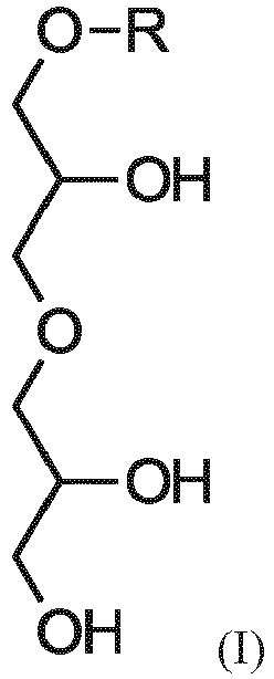
wobei n eine ganze Zahl ist und wobei R' ein verzweigter Alkylrest oder ein verzweigter oder unverzweigter Alkenylrest ist und CnH2n+1 ein aliphatischer, gesättigter linearer Alkylrest ist,
enthalten. - Es kann sich demzufolge auch um ein Gemisch verschiedener Diglycerolester handeln.
- Bevorzugt eingesetzte Diglycerolester weisen einen HLB-Wert von mindestens 6, besonders bevorzugt 6 bis 12 auf, wobei unter dem HLB-Wert die sog. "hydrophilic-lipophilic balance" verstanden wird, die gemäß der Methode nach Griffin wie folgt berechnet wird:

- In einer weiteren bevorzugten Ausführungsform ist R = COCnH2n+1, wobei n eine ganze Zahl von 6-24, bevorzugt 8 bis 18, weiter bevorzugt 10 bis 16, besonders bevorzugt 12 ist. So kann CnH2n+1 beispielsweise n-Hexyl, n-Heptyl, n-Octyl, n-Nonyl, n-Decyl, n-Dodecyl, n-Tridecyl, n-Tetradecyl, n-Hexadecyl oder n-Octadecyl sein.
- In einer weiteren bevorzugten Ausführungsform ist im Aufbaumaterial Diglycerolmonolaurylester enthalten (Diglycerolmonolaurat-Isomer mit dem Molekulargewicht 348 g/mol, welches als Hauptprodukt in einem Gemisch besonders bevorzugt ist). Die vorgenannten Estergruppierungen liegen erfindungsgemäß bevorzugt auch bei den anderen Isomeren des Diglycerols vor.
- Die Menge an Diglycerolester beträgt, bezogen auf das Gesamtgewicht des Aufbaumaterials, 0,01 bis 3,0 Gew.-%, bevorzugt 0,10 bis 2,0 Gew.-%, besonders bevorzugt 0,15 bis 1,50 Gew.-% und ganz besonders bevorzugt 0,20 bis 1,0 Gew.-%.
- Bevorzugt enthalten die erfindungsgemäßen Zusammensetzungen ein Antitropfmittel. In einer weiteren bevorzugten Ausführungsform sind im Aufbaumaterial mindestens 0,05 Gew.-% eines Antitropfmittels enthalten. Die Menge an Antitropfmittel (Antidrippingmittel) beträgt bevorzugt 0,05 bis 5,0 Gew.-%, weiter bevorzugt 0,10 Gew.-% bis 2,0 Gew.-%, besonders bevorzugt 0,10 Gew.-% bis 1,0 Gew.-% mindestens eines Antitropfmittels.
- Als Antitropfmittel wird dem Aufbaumaterial bevorzugt Polytetrafluorethylen (PTFE) zugefügt. PTFE ist in diversen Produktqualitäten kommerziell verfügbar. Hierzu zählen Hostaflon® TF2021 oder aber PTFE-Blends wie Metablen® A-3800 (ca. 40 Gew.-% PTFE, CAS 9002-84-0, und ca. 60 Gew.-% Methylmethacrylat/Butylacrylat Copolymer, CAS 25852-37-3, von Mitsubishi-Rayon) oder Blendex® B449 (ca. 50 Gew.-% PTFE und ca. 50 Gew.-% SAN [aus 80 Gew.-% Styrol und 20 Gew.-% Acrylnitril]) der Firma Chemtura. Bevorzugt wird Blendex® B449 verwendet.
- Als Thermostabilisatoren eignen sich bevorzugt Triphenylphosphin, Tris-(2,4-di-tert-butylphenyl)phosphit (Irgafos® 168), Tetrakis-(2,4-di-tert-butylphenyl)-[1,1-biphenyl]-4,4'-diylbisphosphonit, Trisisooctylphosphat, Octadecyl-3-(3,5-di-tert-butyl-4-hydroxyphenyl)-propionat (Irganox® 1076), Bis-(2,4-dicumylphenyl)-pentaerythritoldiphosphit (Doverphos® S-9228), Bis-(2,6-di-tert-butyl-4-methylphenyl)-pentaerythritoldiphosphit (ADK STAB PEP-36). Sie werden allein oder im Gemisch (z. B. Irganox® B900 (Gemisch aus Irgafos® 168 und Irganox® 1076 im Verhältnis 1:3) oder Doverphos® S-9228 mit Irganox® B900 bzw. Irganox® 1076) eingesetzt. Die Thermostabilisatoren werden bevorzugt in Mengen von 0,003 bis 0,2 Gew.-% eingesetzt.
- Zusätzlich sind optional bis zu 10,0 Gew.-%, bevorzugt 0,10 bis 8,0 Gew.-%, besonders bevorzugt 0,2 bis 3,0 Gew.-% sonstige übliche Additive ("weitere Additive") enthalten. Die Gruppe der weiteren Additive umfasst keine Flammschutzmittel, keine Antitropfmittel und keine Thermostabilisatoren, da diese bereits als Komponenten B, E und F beschrieben sind. Auch umfasst die Gruppe der weiteren Additive keine Glasfasern, Carbonfasern sowie Carbon-Nanotubes, da diese bereits von der Gruppe C erfasst sind. "Weitere Additive" sind auch keine Fließhilfsmittel aus der Gruppe der Diglycerolester, da diese bereits als Komponente D erfasst sind.
- Solche Additive, wie sie üblicherweise bei Polycarbonaten zugesetzt werden, sind insbesondere die in
EP-A 0 839 623 ,WO-A 96/15102 EP-A 0 500 496 oder "Plastics Additives Handbook", Hans Zweifel, 5th Edition 2000, Hanser Verlag, München beschriebenen Antioxidantien, UV-Absorber, IR-Absorber, Antistatika, optischen Aufheller, Lichtstreumittel, Farbmittel wie Pigmente, auch anorganischen Pigmente, Ruß und/oder Farbstoffe, anorganischen Füllstoffe wie Titandioxid oder Bariumsulfat in den für Polycarbonat üblichen Mengen. Diese Additive können einzeln oder auch im Gemisch zugesetzt werden. - Bevorzugte Additive sind spezielle UV-Stabilisatoren, die eine möglichst geringe Transmission unterhalb 400 nm und eine möglichst hohe Transmission oberhalb von 400 nm besitzen. Für den Einsatz in der erfindungsgemäßen Zusammensetzung besonders geeignete Ultraviolett-Absorber sind Benzotriazole, Triazine, Benzophenone und/oder arylierte Cyanoacrylate.
- Besonders geeignete Ultraviolett-Absorber sind Hydroxy-Benzotriazole, wie 2-(3',5'-Bis-(1,1-dimethylbenzyl)-2'-hydroxy-phenyl)-benzotriazol (Tinuvin® 234, BASF, Ludwigshafen), 2-(2'-Hydroxy-5'-(tert.-octyl)-phenyl)-benzotriazol (Tinuvin® 329, BASF, Ludwigshafen),), Bis-(3-(2H-benztriazolyl)-2-hydroxy-5-tert.-octyl)methan (Tinuvin® 360, BASF, Ludwigshafen), 2-(4,6-Diphenyl-1,3,5-triazin-2-yl)-5-(hexyloxy)-phenol (Tinuvin® 1577, BASF, Ludwigshafen), sowie Benzophenone wie 2,4-Dihydroxybenzophenon (Chimasorb® 22 , BASF, Ludwigshafen) und 2-Hydroxy-4-(octyloxy)-benzophenon (Chimassorb® 81, BASF, Ludwigshafen), 2,2-Bis[[(2-cyano-1-oxo-3,3-diphenyl-2-propenyl)oxy]-methyl]-1,3-propandiylester (9CI) (Uvinul® 3030, BASF AG Ludwigshafen), 2-[2-Hydroxy-4-(2-ethylhexyl)oxy]phenyl-4,6-di(4-phenyl)phenyl-1,3,5-triazine (Tinuvin® 1600, BASF, Ludwigshafen), Tetraethyl-2,2'-(1,4-phenylen-dimetliyliden)-bismalonat (Hostavin® B-Cap, Clariant AG) oder N-(2-Ethoxyphenyl)-N'-(2-ethylphenyl)-ethandiamid (Tinuvin® 312, CAS-Nr. 23949-66-8, BASF, Ludwigshafen).
- Besonders bevorzugte spezielle UV-Stabilisatoren sind Tinuvin® 360, Tinuvin® 329 und/oder Tinuvin® 312, ganz besonders bevorzugt sind Tinuvin® 329 und Tinuvin® 312.
- Es können auch Mischungen dieser Ultraviolett-Absorber eingesetzt werden.
- Bevorzugt enthält die Zusammensetzung Ultraviolett-Absorber in einer Menge bis 0,8 Gew.-%, bevorzugt 0,05 Gew.-% bis 0,5 Gew.-% , weiter bevorzugt 0,1 Gew.-% bis 0,4 Gew.-%, bezogen auf die Gesamtzusammensetzung.
- Bevorzugt ist die Zusammensetzung frei von zusätzlichen Entformungsmitteln.
- Besonders bevorzugt ist mindestens ein Thermostabilisator (Komponente F) und gegebenenfalls als weiteres Additiv ein UV-Absorber enthalten, wenn als Füllstoff Glasfasern eingesetzt werden.
- Die Herstellung des Aufbaumaterials, enthaltend die Komponenten A bis D, ggf. ohne B, und ggf. E bis G, erfolgt mit gängigen Einarbeitungsverfahren durch Zusammenführung, Vermischen und Homogenisieren der einzelnen Bestandteile, wobei insbesondere die Homogenisierung bevorzugt in der Schmelze unter Einwirkung von Scherkräften stattfindet. Gegebenenfalls erfolgt das Zusammenführen und Vermischen vor der Schmelzehomogenisierung unter Verwendung von Pulvervormischungen.
- Es können auch Vormischungen aus Granulaten oder Granulaten und Pulvern mit den Komponenten B bis G verwendet werden.
- Es können auch Vormischungen verwendet werden, die aus Lösungen der Mischungskomponenten in geeigneten Lösungsmitteln hergestellt worden sind, wobei gegebenenfalls in Lösung homogenisiert wird und das Lösungsmittel anschließend entfernt wird.
- Insbesondere können hierbei die Komponenten B bis G der erfindungsgemäßen Zusammensetzung durch bekannte Verfahren oder als Masterbatch in das Polycarbonat eingebracht werden.
- Die Verwendung von Masterbatchen ist zum Einbringen der Komponenten B bis G, einzeln oder in Mischung, bevorzugt.
- In diesem Zusammenhang kann das Aufbaumaterial in üblichen Vorrichtungen wie Schneckenextrudern (zum Beispiel Zweischneckenextruder, ZSK), Knetern, Brabender- oder Banbury-Mühlen zusammengeführt, vermischt, homogenisiert und anschließend zu einem Filament oder einem anderen geeigneten Formkörper für additive Fertigungsverfahren extrudiert werden. Es können auch einzelne Komponenten vorgemischt werden und dann die restlichen Ausgangsstoffe einzeln und/oder ebenfalls gemischt hinzugegeben werden.
- Die Zusammenführung und Durchmischung einer Vormischung in der Schmelze kann auch in der Plastifiziereinheit einer Spritzgussmaschine erfolgen. Hierbei wird die Schmelze im anschließenden Schritt direkt in einen Formkörper, insbesondere ein Filament, überführt.
- Ein besonders bevorzugtes Aufbaumaterial umfasst:
- A) 20 Gew.-% bis 99,0 Gew.-% aromatisches Polycarbonat,
- B) 0,0 Gew.-% bis 1,0 Gew.-% mindestens eines Flammschutzmittels, ausgewählt aus der Gruppe Natriumperfluorbutansulfat, Kaliumperfluorbutansulfat, Natriumperfluormethansulfonat, Kaliumperfluormethansulfonat, Natriumperfluoroctansulfat, Kaliumperfluoroctansulfat, Natrium-2,5 - dichlorbenzolsulfat, Kalium-2,5-dichlorbenzolsulfat, Natrium-2,4,5-trichlorbenzolsulfat, Kalium-2,4,5-trichlorbenzolsulfat, Natriummethylphosphonat, Kaliummethylphosphonat, Natrium-(2-phenyl-ethylen)-phosphonat, Kalium-(2-phenyl-ethylen)-phosphonat, Natriumpentachlorbenzoat, Kaliumpentachlorbenzoat, Natrium-2,4,6-trichlorbenzoat, Kalium-2,4,6-trichlorbenzoat, Natrium-2,4-dichlorbenzoat, Kalium-2,4-dichlorbenzoat, Lithiumphenylphosphonat, Natriumdiphenylsulfonsulfonat, Kaliumdiphenylsulfonsulfonat, Natrium-2-formylbenzolsulfonat, Kalium-2-formylbenzolsulfonat, Natrium-(N-benzolsulfonyl)-benzolsulfonamid, Kalium-(N-benzolsulfonyl)-benzolsulfonamid, Trinatriumhexafluoroaluminat, Trikaliumhexafluoroaluminat, Dinatriumhexafluorotitanat, Dikaliumhexafluorotitanat, Dinatriumhexafluorosilikat, Dikaliumhexafluorosilikat, Dinatriumhexafluorozirkonat, Dikaliumhexafluorozirkonat, Natriumpyrophosphat, Kaliumpyrophosphat, Natriummetaphosphat, Kaliummetaphosphat, Natriumtetrafluoroborat, Kaliumtetrafluoroborat, Natriumhexafluorophosphat, Kaliumhexafluorophosphat, Natrium- oder Kalium- oder Lithiumphosphat, Natriumnonafluor-1-butansulfonat, Kaliumnonafluor-1-butansulfonat oder deren Mischungen.
- C) 0,5 Gew.-% bis 50,0 Gew.-% mindestens einer Glasfaser, einer Carbonfaser und/oder Carbon-Nanotubes,
- D) 0,01 Gew.-% bis 3,0 Gew.-% mindestens eines Fließhilfsmittels, ausgewählt aus der Gruppe der Diglycerolester, bevorzugt einer der Formel (I), ganz besonders bevorzugt Diglycerolmonolaurylester,
- E) 0,0 Gew.-% bis 5,0 Gew.-% mindestens eines Antitropfmittels,
- F) 0,0 Gew.-% bis 1,0 Gew.-% mindestens eines Thermostabilisators,
- G) 0,0 Gew.-% bis 10,0 Gew.-% weitere Additive, ausgewählt aus der Gruppe der UV-Absorber, IR-Absorber, Farbmittel, Ruß und/oder anorganischen Füllstoffe.
- Dieses Aufbaumaterial enthält ganz besonders bevorzugt mindestens eine Glasfaser, wobei noch weiter bevorzugt als Verstärkungsfaser nur Glasfaser enthalten ist.
- Alternativ ganz besonders bevorzugt enthält das Aufbaumaterial eine Carbonfaser, wobei noch weiter bevorzugt als Verstärkungsfaser nur Carbonfaser enthalten ist.
- In einer weiteren bevorzugten Ausführungsform weist das Aufbaumaterial eine Schmelze-Volumenfließrate MVR von 2 bis 85 cm3/10 min und besonders bevorzugt von 3 bis 75 cm3/10 min, bestimmt nach ISO 1133 (Prüftemperatur 300°C, Masse 1,2 kg), auf und der E-Modul, bestimmt nach ISO 527, beträgt mindestens 2100 kg*m-1*S-2.
- In einer weiteren bevorzugten Ausführungsform wird das Verfahren innerhalb eines Bauraums durchgeführt und die Temperatur des Bauraums ist ≥ 10 °C (bevorzugt ≥ 25 °C, mehr bevorzugt ≥ 50 °C) geringer als die Glasübergangstemperatur Tg des Aufbaumaterials (bestimmt durch DSC gemäß DIN EN ISO 11357 bei einer Heizrate von 10 °C/min). Damit ist besonders bei komplexen und großen Bauteilen mit langer Fertigungszeit eine deutlich geringere thermische Belastung und bessere Maßhaltigkeit des Bauteils verbunden.
- Die vorliegende Erfindung betrifft weiterhin die Verwendung eines Aufbaumaterials in einem additiven Schmelzschichtungsverfahren, wobei das Aufbaumaterial umfasst:
- A)20 Gew.-% bis 99,0 Gew.-% aromatisches Polycarbonat,
- B)0,0 bis 1,0 Gew.-% mindestens eines Flammschutzmittels,
- C) 0,0 Gew.-% bis 50,0 Gew.-% einer Komponente ausgewählt aus: Glasfasern, Carbonfasern, Carbon-Nanotubes, Graphit, Schlagzähmodifikatoren oder Mischungen aus mindestens zwei hiervon,
- D) 0,01 Gew.-% bis 3,0 Gew.-% mindestens eines Fließhilfsmittels, ausgewählt aus der Gruppe der Diglycerolester,
- E) 0,0 Gew.-% bis 5,0 Gew.-% mindestens eines Antitropfmittels,
- F)0,0 Gew.-% bis 1,0 Gew.-% mindestens eines Thermostabilisators,
- G) 0,0 Gew.-% bis 10,0 Gew.-% weitere Additive.
- Zu den Komponenten A bis G gelten die im Zusammenhang mit dem erfindungsgemäßen Verfahren ausgeführten Details, welche zur Vermeidung von Wiederholungen hier nicht erneut diskutiert werden. Ebenso lassen sich für das Aufbaumaterial in der erfindungsgemäßen Verwendung die gleichen bevorzugten Ausführungsformen anwenden wie im erfindungsgemäßen Verfahren. Es sei lediglich angemerkt, dass vorzugsweise im Aufbaumaterial als Diglycerolester ein Ester der Formel (I)

- mit R = COCnH2n+1 und/oder R = COR',
- wobei n eine ganze Zahl ist und wobei R' ein verzweigter Alkylrest oder ein verzweigter oder unverzweigter Alkenylrest ist und CnH2n+1 ein aliphatischer, gesättigter linearer Alkylrest ist, enthalten ist. Ganz besonders bevorzugt handelt es sich um Diglycerolmonolaurylester.
- Die Herstellung von erfindungsgemäß geeigneten Aufbaumaterialien wird anhand der nachfolgenden Beispiele (s.
WO 2016/087296 A1 ) beschrieben. - Die erfindungsgemäß geeigneten Polycarbonatzusammensetzungen werden auf üblichen Maschinen, wie beispielsweise Mehrwellenextrudern, durch Compoundierung, gegebenenfalls unter Zugabe von Additiven und anderen Zuschlagstoffen, bei Temperaturen zwischen 280°C und 360°C hergestellt.
- Die erfindungsgemäßen Compounds zu den folgenden Beispielen wurden auf einem Extruder ZE 25 der Fa. Berstorff mit einem Durchsatz von 10 kg/Std. hergestellt. Die Schmelzetemperatur betrug 275 °C.
- Es wurden als Polycarbonatbasis A Mischungen aus den Komponenten A-1, A-2, A-3, A-4, A-6 bzw. A-7 eingesetzt.
- Komponente A-1: Lineares Polycarbonat auf Basis von Bisphenol A mit einer Schmelze-Volumenfließrate MVR von 9,5 cm3/10 min (gemäß ISO 1133, bei einer Prüftemperatur 300°C und 1,2 kg Belastung).
- Komponente A-2: Lineares Polycarbonat in Pulverform auf Basis von Bisphenol A mit einer Schmelze-Volumenfließrate MVR von 6 cm3/10 min (gemäß ISO 1133, bei einer Prüftemperatur von 300°C und 1,2 kg Belastung).
- Komponente A-3: Lineares Polycarbonat auf Basis von Bisphenol A mit einer Schmelze-Volumenfließrate MVR von 12,5 cm3/10 min (gemäß ISO 1133, bei einer Prüftemperatur 300°C und 1,2 kg Belastung).
- Komponente A-4: Lineares Polycarbonat auf Basis von Bisphenol A mit einer Schmelze-Volumenfließrate MVR von 6 cm3/10 min (gemäß ISO 1133, bei einer Prüftemperatur 300°C und 1,2 kg Belastung).
- Komponente A-6: Pulver eines linearen Polycarbonates auf Basis von Bisphenol A mit einer Schmelze-Volumenfließrate MVR von 19 cm3/10 min (gemäß ISO 1133, bei einer Prüftemperatur 300°C und 1,2 kg Belastung).
- Komponente A-7: Lineares Polycarbonat auf Basis von Bisphenol A mit einer Schmelze-Volumenfließrate MVR von 19 cm3/10 min (gemäß ISO 1133, bei einer Prüftemperatur 300°C und 1,2 kg Belastung).
- Komponente B: Kaliumperfluor-1-butansulfonat, kommerziell erhältlich als Bayowet® C4 der Firma Lanxess, Leverkusen, Deutschland, CAS-Nr. 29420-49-3.
- Komponente C-1: CS108F-14P, geschnittene Kurzglasfasern (nicht anbindend) der Firma 3B mit einem durchschnittlichen Faserdurchmesser von 14 µm und einer durchschnittlichen Faserlänge von 4,0 mm vor der Compoundierung.
- Komponente C-2: CS 7942, geschnittene Kurzglasfasern (anbindend) der Firma Lanxess AG mit einem durchschnittlichen Faserdurchmesser von 14 µm und einer durchschnittlichen Faserlänge von 4,5 mm vor der Compoundierung.
- Komponente C-3: Carbonfaser CF Tenax A HT C493, geschnittene Kohlenstoff-Kurzfaser der Firma Toho Tenax Europe GmbH Germany mit thermoplastischem Präparationsauftrag und mit einer durchschnittlichen Schnittlänge von 6 mm vor der Compoundierung.
- Komponente C-4: CNT; Baytubes C150 HP, Agglomerate von Multi-Wall Nanoröhrchen mit niedrigem Außendurchmesser, enger Durchmesserverteilung und ultra-hoch Längen-zu Durchmesser-Verhältnis. Anzahl Wände: 3-15 / Außendurchmesser: 13-16 nm / Außendurchmesserverteilung: 5-20 nm / Länge: 1 bis >10 µm / Innendurchmesser: 4 nm / Innendurchmesserverteilung: 2-6 nm.
- Komponente C-5: Carbonfaser AC 3101; geschnittene Kohlenstoff-Kurzfaser der Firma Dow Aksa (Türkei) mit einer durchschnittlichen Länge von 6 mm vor der Compoundierung.
- Komponente C-6: Carbonfaser Tairyfil CS2516, geschnittene Kohlenstoff-Kurzfaser der Firma Formosa Plastic Corporation Taiwan mit einer durchschnittlichen Länge von 6 mm vor der Compoundierung.
- Komponente C-7: Glasfaser CS Special 7968, geschnittene Kurzglasfasern der Firma Lanxess AG mit einem durchschnittlichen Faserdurchmesser von 11 µm und einer durchschnittlichen Faserlänge von 4,5 mm vor der Compoundierung.
- Komponente C-8: Glasfaser CSG 3PA-830, geschnittene Flachglasfaser der Firma Nittobo mit einem Dicken-/Längenverhältnis von 1:4.
- Komponente C-9: Glasfaser MF7980, gemahlene Glasfaser der Firma Lanxess. Unbeschlichtetes E-Glas mit einer Faserdicke von 14 µm und einer mittleren Faserlänge von 190 µm.
- Komponente D: Poem DL-100 (Diglycerolmonolaurat) der Fa. Riken Vitamin als Fließhilfsmittel.
- Komponente E: Polytetrafluorethylen (Blendex® B449 (ca. 50 Gew.-% PTFE und ca. 50 Gew.-% SAN [aus 80 Gew.-% Styrol und 20 Gew.-% Acrylnitril] der Firma Chemtura).
- Komponente F: Triisooctylphosphat (TOF) der Firma Lanxess AG.
- Komponente G-1: Glycerinmonostearat (GMS) der Firma Emery Oleochemicals.
- Komponente G-2: Pentareythrittetrastearat (PETS) der Firma Emery Oleochemicals.
- Komponente G-3: Elvaloy 1820 AC; Ethylen-Methylacrylat-copolymer der Firma Dupont.
- Die Schlagzähigkeit nach Charpy wurde nach ISO 7391/179eU an einseitig angespritzten Prüfstäben der Dimension 80 x 10 x 4 mm bei Raumtemperatur gemessen.
- Die Kerbschlagzähigkeit nach Charpy wurde nach ISO 7391/179A an einseitig angespritzten Prüfstäben der Dimension 80 x 10 x 3 mm bei Raumtemperatur gemessen.
- Die Vicat-Erweichungstemperatur VST/B50 als Maß für die Wärmeformbeständigkeit wurde gemäß ISO 306 an Prüfkörpern der Abmessung 80 x 10 x 4 mm mit einer Stempellast von 50 N und einer Aufheizgeschwindigkeit von 50°C/h mit dem Gerät Coesfeld Eco 2920 der Firma Coesfeld Materialtest bestimmt.
- Das Brandverhalten wurde nach UL94 V an Stäben der Abmessung 127 x 12,7 x 1,0 mm, 127 x 12,7 x 1,5 mm und 127 x 12,7 x 3 mm gemessen. Zur Bestimmung der Brandklasse wurden jeweils fünf Versuche durchgeführt, und zwar zunächst nach Lagerung über 48h bei 23°C und anschließend bei Lagerung über 7 Tage bei 70°C.
- Das Brandverhalten wurde nach UL94-5V an Stäben der Abmessung 127 x 12,7 x 1,5 mm, 127 x 12,7 x 2,0 mm und 127 x 12,7 x 3,0 mm sowie Platten der Abmessung 150 x 105 x 1,5 mm, 150 x 105 x 2,0 mm, 150 x 105 x 3,0 mm gemessen.
- Der E-Modul wurde gemäß ISO 527 an einseitig angespritzten Schulterstäben mit einem Kern der Dimension 80 x 10 x 4 mm gemessen.
- Die Bestimmung der Schmelzviskositäten erfolgte nach ISO 11443 (Kegelplatteanordnung).
- Die Bestimmung des Schmelze-Volumenfließrate (MVR) erfolgte nach ISO 1133 (bei einer Prüftemperatur von 300 °C, Masse 1,2 kg) mit dem Gerät Zwick 4106 der Firma Zwick Roell.
-
Tabelle 1a: Erfindungsgemäß geeignete Aufbaumaterialien, enthaltend Glasfasern, und Vergleichsbeispiele 1V und 4V Beispiel IV 2 3 4V 5 6 A-1 [Gew.-%] 79,35 79,35 79,35 70 70 70 A-2 [Gew.-%] 3,65 3,65 3,65 3 3 3 A-2 Pulver [Gew.-%] 6,29 6,09 5,89 6,29 6,09 5,89 B [Gew.-%] 0,2 0,2 0,2 0,2 0,2 0,2 C-1 [Gew.-%] 10 10 10 - - - C-2 [Gew.-%] - - - 20 20 20 F [Gew.-%] 0,01 0,01 0,01 0,01 0,01 0,01 D [Gew.-%] - 0,2 0,4 - 0,2 0,4 E [Gew.-%] 0,5 0,5 0,5 0,5 0,5 0,5 MVR [cm3/10 min] 5,5 10,8 16,1 4,8 10,3 20,8 VST/B50 [°C] 148 144,9 141,7 149,3 146,2 143,2 Charpy-Schlagzähigkeit bei RT [kJ/m2] 193 149 111 48 59 56 E-Modul [N/mm2] 3933 4080 4147 5869 6062 6194 UL 94 V 1,5 mm Bewertung V0 V0 V0 V0 V0 V0 - In Tabelle 1a sind zu Aufbaumaterialien 2, 3, 5 und 6 wichtige Eigenschaften angegeben. Dem sind die Vergleichsbeispiele 1V und 4V gegenübergestellt. Aus der Tabelle ist zu erkennen, dass die Zusammensetzungen gemäß den Vergleichsbeispielen, welche keinen Diglycerolester enthalten, deutlich schlechtere Schmelze-Volumenfließraten MVR aufweisen.
- Die erfindungsgemäß geeigneten Aufbaumaterialien zeigen neben der erheblichen Verbesserung der Schmelze-Volumenfließrate und der Verbesserung der Schmelzviskosität eine Erhöhung des E-Moduls (Steifigkeit).
Tabelle 1b: Erfindungsgemäß geeignete Aufbaumaterialien, enthaltend Glasfasern, FR-Additiv und Vergleichsbeispiele 7V und 10V Die Werte für die Schmelzviskositäten in der folgenden Tabelle sind jeweils angegeben zu den Scherraten in [1/sec]. Beispiel 7V 8 9 10V 11 12 A-1 [Gew.-%] 70 70 70 70 70 70 A-4 [Gew.-%] 3,00 3,00 3,00 3,00 3,00 3,00 A-2 [Gew.-%] 6,29 6,09 5,89 6,3 6,1 5,9 C-2 [Gew.-%] 20 20 20 20 20 20 B [Gew.-%] 0,2 0,2 0,2 0,2 0,2 0,2 E [Gew.-%] 0,5 0,5 0,5 0,5 0,5 0,5 D [Gew.-%] - 0,2 0,4 - 0,2 0,4 F [Gew.-%] 0,01 0,01 0,01 - - - Prüfungen: MVR [ml/10 min] 4,8 11,1 17,6 4,7 10,2 19,4 IMVR20' [ml/10 min] 4,8 11,9 19,7 4,9 12,1 20,8 Schmelzvisk. bei 300°C eta 50 [Pas] 782 431 294 667 379 286 eta 100 [Pas] 672 375 260 627 346 254 eta 200 [Pas] 583 326 220 542 303 212 eta 500 [Pas] 454 265 175 425 252 168 eta 1000 [Pas] 350 216 147 329 210 143 eta 1500 [Pas] 291 186 129 279 181 128 eta 5000 [Pas] 152 109 79 141 102 77 Schmelzvisk. bei 320°C eta 50 [Pas] 413 195 141 269 166 124 eta 100 [Pas] 375 177 130 244 153 112 eta 200 [Pas] 336 157 114 214 135 98 eta 500 [Pas] 277 134 92 182 109 80 eta 1000 [Pas] 229 115 79 153 95 67 eta 1500 [Pas] 197 101 73 138 87 62 eta 5000 [Pas] 109 65 52 83 58 44 Schmelzvisk. bei 340°C eta 50 [Pas] 199 111 - 199 95 - eta 100 [Pas] 185 104 83 184 90 - eta 200 [Pas] 162 92 77 160 86 61 eta 500 [Pas] 137 78 65 131 74 54 eta 1000 [Pas] 120 70 54 112 65 48 eta 1500 [Pas] 109 66 49 102 59 44 eta 5000 [Pas] 70 46 36 67 42 32 Vicat VSTB 120 [°C] 153,1 148,2 145,9 153,3 148,6 145,8 Schlagversuch ISO7391/179eU 4mm RT [kJ/m2] 59 66 65 61 66 64 Zugversuch Streckspannung [N/mm2] 102 106 112 101 108 - Streckdehnung [%] 3,3 3,2 3,2 3,3 3,3 - Reißfestigkeit [N/mm2] 101 106 111 100 108 11 Reiß dehnung [%] 3,3 3,2 3,1 3,5 3,3 3,1 E-Modul [N/mm2] 5972 6050 6295 5834 6118 6246 UL94V in 1,5 mm (48h 23°C) V1 V1 V1 V0 V1 V1 Einzelbewertung V0/V1/V2/Vn.b. 3/2/-/- 3/2/-/- -/5/-/- 5/-/-/- 3/2/-/- 3/2/-/- Nachbrennzeit [s] 60 88 80 49 65 77 Nachbrennzeit (1. Brennsatz ) [s] - - - - - - (7d 70°C ) V1 V1 V1 V1 V1 V1 Einzelbewertung V0/V1/V2/Vn.b. 4/1/-/- 3/2/-/- 3/2/-/- 1/4/-/- 4/1/-/- 3/2/-/- Nachbrennzeit [s] 48 69 72 102 62 79 Nachbrennzeit (1. Brennsatz) [s] 75 - - - - - Gesamtbewertung V1 V1 V1 V1 V1 V1 Vn.b.: nicht bestanden - In Tabelle 1b sind zu erfindungsgemäß geeigneten Aufbaumaterialien 8, 9, 11 und 12 wichtige Eigenschaften angegeben. Dem sind die Vergleichsbeispiele 7V und 10V gegenübergestellt. Aus der Tabelle ist zu erkennen, dass die Zusammensetzungen gemäß den Vergleichsbeispielen, welche keinen Diglycerolester enthalten, deutlich schlechtere Schmelze-Volumenfließraten MVR aufweisen. Die Fließkurven der erfindungsgemäß geeigneten Aufbaumaterialien zeigen bei den verschiedenen Messtemperaturen über den gesamten Scherbereich jeweils deutlich reduzierte Schmelzviskositäten, was eine verbesserte Fließfähigkeit bedeutet.
- Die erfindungsgemäß geeigneten Aufbaumaterialien zeigen neben der erheblichen Verbesserung der rheologischen Eigenschaften eine Erhöhung des E-Moduls (Steifigkeit) unter Beibehaltung der guten Brandeigenschaften.
Tabelle 1c: Erfindungsgemäß geeignete Aufbaumaterialien, enthaltend Glasfasern und FR-Additiv, und Vergleichsbeispiele 13V und 16V Die Werte für die Schmelzviskositäten in der folgenden Tabelle sind jeweils angegeben zu den Scherraten in [1/sec]. Beispiele 13V 14 15 16V 17 18 A-7 [Gew.-%] 30,00 30,00 30,00 30,00 30,00 30,00 A-2 [Gew.-%] 50,42 50,42 50,42 50,42 50,42 50,42 A-6 [Gew.-%] 5,55 5,35 5,15 5,54 5,34 5,14 C-1 [Gew.-%] 14,00 14,00 14,00 14,00 14,00 14,00 D [Gew.-%] - 0,20 0,40 - 0,20 0,40 B [Gew.-%] 0,03 0,03 0,03 0,03 0,03 0,03 F [Gew.-%] - - - 0,01 0,01 0,01 Prüfungen: MVR [ml/10 min] 7,2 13,4 16,5 7,4 13,5 22,6 IMVR20' [ml/10 min] 7,2 13,6 16,8 7,6 14,2 24,2 Schmelzvisk. bei 300°C eta 50 [Pas] 623 492 371 666 493 370 eta 100 [Pas] 577 438 313 568 416 302 eta 200 [Pas] 502 378 268 504 354 247 eta 500 [Pas] 400 313 231 408 299 207 eta 1000 [Pas] 316 258 197 328 247 176 eta 1500 [Pas] 268 222 173 274 213 157 eta 5000 [Pas] 139 119 102 142 119 94 Schmelzvisk. bei 320°C eta 50 [Pas] 349 286 270 391 355 243 eta 100 [Pas] 337 248 222 327 286 197 eta 200 [Pas] 297 235 183 293 233 165 eta 500 [Pas] 252 198 149 250 194 133 eta 1000 [Pas] 214 165 130 211 166 116 eta 1500 [Pas] 186 146 119 185 148 105 eta 5000 [Pas] 108 88 78 103 95 72 Schmelzvisk. bei 340°C eta 50 [Pas] 169 232 164 278 255 115 eta 100 [Pas] 168 186 137 204 207 109 eta 200 [Pas] 167 148 114 192 171 99 eta 500 [Pas] 147 127 99 162 142 83 eta 1000 [Pas] 125 110 86 140 124 73 eta 1500 [Pas] 112 101 79 127 113 69 eta 5000 [Pas] 78 70 54 83 71 52 Vicat VSTB 50 [°C] 150,2 146,9 145,0 150,5 146,3 143,8 UL94V in 3.0mm (48h 23°C) V0 V0 V0 V0 V0 V0 Einzelbewertung V0/V1/V2/Vn.b. 5/-/-/- 5/-/-/- 5/-/-/- 5/-/-/- 5/-/-/- 5/-/-/- Nachbrennzeit [s] 24 28 29 32 21 41 Nachbrennzeit (1. Brennsatz ) [s] - - - - - - (7d 70°C) V0 V0 V0 V0 V0 V0 Einzelbewertung V0/V1/V2/Vn.b. 5/-/-/- 5/-/-/- 5/-/-/- 5/-/-/- 5/-/-/- 5/-/-/- Nachbrennzeit [s] 23 22 33 26 24 22 Nachbrennzeit (1. Brennsatz ) [s] - - - - - - Gesamtbeurteilung [s] V0 V0 V0 V0 V0 V0 Vn.b.: nicht bestanden - In Tabelle 1c sind zu erfindungsgemäß geeigneten Aufbaumaterialien 14, 15, 17 und 18 wichtige Eigenschaften angegeben. Dem sind die Vergleichsbeispiele 13V und 16V gegenübergestellt. Aus der Tabelle ist zu erkennen, dass die Zusammensetzungen gemäß den Vergleichsbeispielen, welche keinen Diglycerolester enthalten, deutlich schlechtere Schmelze-Volumenfließraten MVR aufweisen. Die Fließkurven der erfindungsgemäß geeigneten Aufbaumaterialien zeigen bei den verschiedenen Messtemperaturen über den gesamten Scherbereich jeweils deutlich reduzierte Schmelzviskositäten, was eine verbesserte Fließfähigkeit bedeutet.
- Die erfindungsgemäß geeigneten Aufbaumaterialien zeigen überraschenderweise neben der erheblichen Verbesserung der rheologischen Eigenschaften auch gute Brandeigenschaften.
Tabelle 1d: Erfindungsgemäß geeignete Aufbaumaterialien, enthaltend Glasfasern und FR-Additiv, und Vergleichsbeispiele 19V und 22V Die Werte für die Schmelzviskositäten in der folgenden Tabelle sind jeweils angegeben zu den Scherraten in [1/sec]. Beispiel 19V 20 21 22V 23 24 A-7 [Gew.-%] 73,00 73,00 73,00 73,00 73,00 73,00 A-6 [Gew.-%] 4,94 4,74 4,54 4,93 4,73 4,53 C-7 [Gew.-%] 20,00 20,00 20,00 20,00 20,00 20,00 B [Gew.-%] 0,06 0,06 0,06 0,06 0,06 0,06 G-3 [Gew.-%] 2,00 2,00 2,00 2,00 2,00 2,00 D [Gew.-%] - 0,20 0,40 - 0,20 0,40 F [Gew.-%] - - - 0,01 0,01 0,01 Prüfungen: MVR [ml/10 min] 8,5 15,7 33,4 8,2 18,2 28,9 IMVR20' [ml/10 min] 8,7 16,1 32,3 8,7 18,9 28,3 Vicat VSTB50 [°C] 151,8 147,6 143,7 151,4 147,9 144 Schmelzvisk. bei 300°C eta 50 [Pas] 462 308 148 508 291 193 eta 100 [Pas] 415 255 135 449 260 176 eta 200 [Pas] 369 242 124 399 235 157 eta 500 [Pas] 302 203 107 320 200 133 eta 1000 [Pas] 236 167 94 250 167 117 eta 1500 [Pas] 201 143 87 213 144 104 eta 5000 [Pas] 108 83 57 117 86 65 Schmelzvisk. bei 320°C eta 50 [Pas] 261 182 97 287 183 130 eta 1 00 [Pas] 247 164 85 266 159 111 eta 200 [Pas] 238 149 77 239 139 101 eta 500 [Pas] 203 128 67 204 124 88 eta 1000 [Pas] 169 111 60 169 108 77 eta 1500 [Pas] 145 99 56 144 97 71 eta 5000 [Pas] 89 61 40 85 61 47 Schmelzvisk. bei 340°C eta 50 [Pas] 159 99 60 183 120 76 eta 100 [Pas] 151 97 56 168 105 71 eta 200 [Pas] 138 88 49 156 94 63 eta 500 [Pas] 122 80 42 137 83 58 eta 1000 [Pas] 108 72 39 119 74 51 eta 1500 [Pas] 98 66 35 105 68 47 eta 5000 [Pas] 65 45 28 68 46 35 UL94V in 1,0 mm (48h 23°C) V1 V2 V2 V2 V1 V2 Einzelbew. V0/V1/V2/Vn.b. 4/1/-/- 3/-/2/- 2/1/2/- 3/1/1/- 3/2/-/- -/-/5/- Nachbrennzeit [s] 73 61 55 81 97 72 Nachbrennzeit (1. Brennsatz ) [s] 118 - - >115 - - (7d 70°C) V2 V2 V2 V2 V2 V2 Einzelbew. V0/V1/V2/Vn.b. 3/-/2/- 1/2/2/- 1/-/4/- -/3/2/- 1/-/4/- -/-/5/- Nachbrennzeit [s] 67 92 63 118 54 75 Nachbrennzeit (1. Brennsatz ) [s] - - - - - - Gesamtbewertung V2 V2 V2 V2 V2 V2 Vn.b.: nicht bestanden - In Tabelle 1d sind zu erfindungsgemäß geeigneten Aufbaumaterialien 20, 21, 23 und 24 wichtige Eigenschaften angegeben. Dem sind die Vergleichsbeispiele 19V und 22V gegenübergestellt. Aus der Tabelle ist zu erkennen, dass die Zusammensetzungen gemäß den Vergleichsbeispielen, welche keinen Diglycerolester enthalten, deutlich schlechtere Schmelze-Volumenfließraten MVR aufweisen. Die Fließkurven der erfindungsgemäß geeigneten Aufbaumaterialien zeigen bei den verschiedenen Messtemperaturen über den gesamten Scherbereich jeweils deutlich reduzierte Schmelzviskositäten, was eine verbesserte Fließfähigkeit bedeutet.
Tabelle 1e: Erfindungsgemäß geeignete Aufbaumaterialien, enthaltend Glasfasern, und Vergleichsbeispiele 25V und 28V Die Werte für die Schmelzviskositäten in der folgenden Tabelle sind jeweils angegeben zu Scherraten in [1/sec]. den Beispiel 25V 26 27 28V 29 30 A-3 [Gew.-%] 63,00 63,00 63,00 63,00 63,00 63,00 A-2 [Gew.-%] 7,00 6,80 6,60 6,99 6,79 6,59 C-8 [Gew.-%] 30,00 30,00 30,00 30,00 30,00 30,00 D [Gew.-%] - 0,20 0,40 - 0,20 0,40 F [Gew.-%] - - - 0,01 0,01 0,01 Prüfungen MVR 300°C/1,2 kg [cm3/10 min] 4,5 9,1 15,3 4,5 8,8 15,3 IMVR20' 300°C/1,2 kg [cm3/10 min] 5,1 10,4 19,9 5,6 10,9 19,0 Schmelzvisk. bei 300°C eta 50 [Pas] 763 532 376 721 540 420 eta 100 [Pas] 669 483 340 677 455 367 eta 200 [Pas] 581 430 301 591 377 324 eta 500 [Pas] 452 346 249 460 302 266 eta 1000 [Pas] 346 274 205 348 258 218 eta 1500 [Pas] 294 235 174 303 222 189 eta 5000 [Pas] 154 129 104 158 132 113 Schmelzvisk. bei 320°C eta 50 [Pas] 397 278 133 372 299 220 eta 1 00 [Pas] 60 237 128 365 255 180 eta 200 [Pas] 321 209 114 325 228 165 eta 500 [Pas] 265 176 95 250 199 132 eta 1000 [Pas] 221 154 83 206 167 110 eta 1500 [Pas] 190 139 75 170 149 95 eta 5000 [Pas] 110 88 55 100 93 68 Schmelzvisk. bei 340°C eta 50 [Pas] 178 114 84 215 120 104 eta 100 [Pas] 168 106 72 187 115 92 eta 200 [Pas] 153 95 65 159 105 82 eta 500 [Pas] 131 84 57 141 92 66 eta 1000 [Pas] 118 76 51 117 89 57 eta 1500 [Pas] 112 71 48 113 83 52 eta 5000 [Pas] 75 55 35 73 65 42 - In Tabelle 1e sind zu erfmdungsgemäß geeigneten Aufbaumaterialien 26, 27, 29 und 30 wichtige Eigenschaften angegeben. Dem sind die Vergleichsbeispiele 25V und 28V gegenübergestellt. Aus der Tabelle ist zu erkennen, dass die Zusammensetzungen gemäß den Vergleichsbeispielen, welche keinen Diglycerolester enthalten, deutlich schlechtere Schmelze-Volumenfließraten MVR aufweisen. Die Fließkurven der erfindungsgemäß geeigneten Aufbaumaterialien zeigen bei den verschiedenen Messtemperaturen über den gesamten Scherbereich jeweils deutlich reduzierte Schmelzviskositäten, was eine verbesserte Fließfähigkeit bedeutet.
Tabelle 1f: Erfindungsgemäß geeignete Aufbaumaterialien, enthaltend Glasfasern, und Vergleichsbeispiele 31V und 34V Die Werte für die Schmelzviskositäten in der folgenden Tabelle sind jeweils angegeben zu den Scherraten in [1/sec]. zu den Beispiele 31V 32 33 34V 35 36 A-3 [Gew.-%] 63,00 63,00 63,00 63,00 63,00 63,00 A-2 [Gew.-%] 7,00 6,80 6,60 6,99 6,79 6,59 C-9 [Gew.-%] 30,00 30,00 30,00 30,00 30,00 30,00 D [Gew.-%] - 0,20 0,40 - 0,20 0,40 F [Gew.-%] - - - 0,01 0,01 0,01 Prüfungen MVR 300°C/1,2 kg [cm3/10 min] 5,3 10,1 19,4 5,5 9,9 19,8 IMVR20' 300°C/1,2 kg [cm3/10 min] 5,9 13,4 24,3 5,8 12,6 24,8 Schmelzvisk. bei 300°C eta 50 [Pas] 699 586 436 630 534 397 eta 100 [Pas] 633 531 390 628 523 390 eta 200 [Pas] 580 483 361 579 486 369 eta 500 [Pas] 480 408 313 479 411 302 eta 1000 [Pas] 384 334 263 381 336 264 eta 1500 [Pas] 317 282 230 318 284 227 eta 5000 [Pas] 157 145 125 158 147 122 Schmelzvisk. bei 320°C eta 50 [Pas] 328 250 175 260 281 200 eta 100 [Pas] 305 237 172 255 267 191 eta 200 [Pas] 282 233 161 250 254 182 eta 500 [Pas] 250 212 152 237 230 169 eta 1000 [Pas] 217 186 138 211 201 153 eta 1500 [Pas] 193 167 124 192 180 142 eta 5000 [Pas] 111 104 81 116 116 91 Schmelzvisk. bei 340°C eta 50 [Pas] 142 105 69 174 147 90 eta 100 [Pas] 137 102 66 173 140 87 eta 200 [Pas] 133 99 62 166 137 84 eta 500 [Pas] 128 96 60 156 120 82 eta 1000 [Pas] 119 93 56 142 105 79 eta 1500 [Pas] 112 88 56 132 95 77 eta 5000 [Pas] 77 65 46 85 69 58 - In Tabelle 1f sind zu erfindungsgemäß geeigneten Aufbaumaterialien 32, 33, 35 und 36 wichtige Eigenschaften angegeben. Dem sind die Vergleichsbeispiele 31V und 34V gegenübergestellt. Aus der Tabelle ist zu erkennen, dass die Zusammensetzungen gemäß den Vergleichsbeispielen, welche keinen Diglycerolester enthalten, deutlich schlechtere Schmelze-Volumenfließraten MVR aufweisen. Die Fließkurven der erfindungsgemäß geeigneten Aufbaumaterialien zeigen bei den verschiedenen Messtemperaturen über den gesamten Scherbereich jeweils deutlich reduzierte Schmelzviskositäten, was eine verbesserte Fließfähigkeit bedeutet.
Tabelle 1g: Erfindungsgemäß geeignete Aufbaumaterialien, enthaltend Glasfasern, und Vergleichsbeispiel 37V Rezeptur 37V 38 39 40 41 42 43 A-1 [Gew.-%] 79,35 79,35 79,35 74,35 74,35 69,35 69,35 A-4 [Gew.-%] 3,65 3,65 3,65 3,65 3,65 3,65 3,65 A-2 [Gew.-%] 5,85 6,1 5,9 6,1 5,9 6,1 5,9 G-2 [Gew.-%] 0,45 - - - - - - D [Gew.-%] - 0,2 0,4 0,2 0,4 0,2 0,4 Blendex 449 [Gew.-%] 0,2 0,2 0,2 0,2 0,2 0,2 0,2 E [Gew.-%] 0,5 0,5 0,5 0,5 0,5 0,5 0,5 C-1 [Gew.-%] 10 10 10 15 15 20 20 Prüfungen: MVR [cm3/10 min] 5,7 10,4 16,6 8,1 11,9 6,6 11,9 IMVR20' [cm3/10 min] 5,8 11,1 17,3 8,4 12,3 7,2 11,0 Delta MVR/IMVR20' 0,1 0,7 0,7 0,3 0,4 0,6 -0,9 KET [°C] 137 137 133 137 132 136 133 UL94-5V in 3,0mm Stabprüfung ja ja ja ja ja ja ja Plattenprüfung bestanden bestanden bestanden bestanden bestanden bestanden bestanden Klassifizierung 94-5VA 94-5VA 94-5VA 94-5VA 94-5VA 94-5V A 94-5VA UL94-5V in 2,0mm Stabprüfung ja ja ja ja ja ja ja Plattenprüfung nein nein nein bestanden bestanden bestanden bestanden Klassifizierung 94-5VB 94-5VB 94-5VB 94-5VA 94-5VA 94-5VA 94-5VA UL94-5V in 1,5mm Stabprüfung ja nein nein nein ja ja nein Plattenprüfung nein - - - nein bestanden - Klassifizierung 94-5VB - - - 94-5VB 94-5VA - - In Tabelle 1g sind zu erfindungsgemäß geeigneten Aufbaumaterialien 38 bis 43 wichtige Eigenschaften angegeben. Dem ist das Vergleichsbeispiel 37V gegenübergestellt. Aus der Tabelle ist zu erkennen, dass die Zusammensetzung gemäß dem Vergleichsbeispiel, welches keinen Diglycerolester enthält, eine deutlich schlechtere Schmelze-Volumenfließrate MVR aufweist.
- Beispiel 41 zeigt, dass trotz Verbesserung der Fließrate die UL 94-5V Klassifizierung im Brandtest erhalten bleibt. Beispiel 42 zeigt, dass bei annähernd gleichbleibendem MVR sogar eine höhere Wertung des 94-5V Tests zu erreichen ist (von 5VB auf 5VA bei 1,5 mm)
Tabelle 2a: Erfindungsgemäß geeignete Aufbaumaterialien, enthaltend Carbonfasern, und Vergleichsbeispiel 44V Die Werte für die Schmelzviskositäten in der folgenden Tabelle sind jeweils angegeben zu den Scherraten in [1/sec]. Beispiel 44V 45 46 47 A-3 [Gew.-%] 81,00 81,00 81,00 81,00 A-2 [Gew.-%] 7,00 6,79 6,69 6,59 C-3 [Gew.-%] 12,00 12,00 12,00 12,00 D [Gew.-%] - 0,20 0,30 0,40 F [Gew.-%] - 0,01 0,01 0,01 Ergebnisse MVR [cm3/10 min] 7,0 8,6 11,7 20,5 IMVR20' [cm3/10 min] 7,6 9,9 16,9 24,1 Schmelzvisk. bei 300°C eta 50 [Pas] 535 492 468 401 eta 100 [Pas] 497 466 441 379 eta 200 [Pas] 452 423 401 343 eta 500 [Pas] 365 346 327 287 eta 1000 [Pas] 292 278 264 233 eta 1500 [Pas] 253 241 226 203 eta 5000 [Pas] 138 130 124 116 Schmelzvisk. bei 320°C eta 50 [Pas] 254 236 240 216 eta 100 [Pas] 250 227 235 200 eta 200 [Pas] 249 225 221 199 eta 500 [Pas] 217 198 192 176 eta 1000 [Pas] 184 167 163 154 eta 1500 [Pas] 162 147 143 134 eta 5000 [Pas] 100 93 91 87 Schmelzvisk. bei 340°C eta 50 [Pas] 149 118 109 101 eta 100 [Pas] 146 115 107 99 eta 200 [Pas] 139 114 105 96 eta 500 [Pas] 126 113 103 88 eta 1000 [Pas] 107 102 99 77 eta 1500 [Pas] 102 93 90 72 eta 5000 [Pas] 70 64 64 50 - In Tabelle 2a sind zu erfindungsgemäß geeigneten Aufbaumaterialien 45 bis 47 wichtige Eigenschaften angegeben. Dem ist das Vergleichsbeispiel 44V gegenübergestellt. Aus der Tabelle ist zu erkennen, dass die Zusammensetzungen gemäß dem Vergleichsbeispiel, welches keinen Diglycerolester enthält, deutlich schlechtere Schmelze-Volumenfließraten MVR aufweist. Die Fließkurven der erfindungsgemäß geeigneten Aufbaumaterialien zeigen bei den verschiedenen Messtemperaturen über den gesamten Scherbereich jeweils deutlich reduzierte Schmelzviskositäten, was eine verbesserte Fließfähigkeit bedeutet.
Tabelle 2b: Erfindungsgemäß geeignete Aufbaumaterialien, enthaltend Carbonfasern, und Vergleichsbeispiele 48V und 52V Die Werte für die Schmelzviskositäten in der folgenden Tabelle sind jeweils angegeben zu den Scherraten in [1/sec]. Rezeptur 48V 49 50 51 52V 53 54 55 A-3 [Gew.-%] 81,00 81,00 81,00 81,00 81,00 81,00 81,00 81,00 A-2 [Gew.-%] 7,00 6,79 6,69 6,59 7,00 6,79 6,69 6,59 C-5 [Gew.-%] 12,00 12,00 12,00 12,00 - - - - C-6 [Gew.-%] - - - - 12,00 12,00 12,00 12,00 D [Gew.-%] - 0,20 0,30 0,40 - 0,20 0,30 0,40 F [Gew.-%] - 0,01 0,01 0,01 - 0,01 0,01 0,01 Prüfungen: MVR [cm3/10 min] 6,8 10,6 12,6 18,3 6,3 7,9 9,1 10,4 IMVR20' [cm3/10 min] 7,5 13,2 17,4 25,8 7,0 10,4 11,1 13,6 Schmelzvisk. bei 300°C eta 50 [Pas] 456 366 349 302 513 456 453 452 eta 100 [Pas] 424 350 329 284 512 446 427 423 eta 200 [Pas] 388 322 303 270 458 411 391 386 eta 500 [Pas] 330 275 263 236 376 339 324 320 eta 1000 [Pas] 269 226 222 197 299 275 263 257 eta 1500 [Pas] 233 197 196 173 257 239 228 223 eta 5000 [Pas] 126 111 111 103 135 126 123 121 Schmelzvisk. bei 320°C eta 50 [Pas] 236 164 146 90 350 252 243 225 eta 100 [Pas] 217 158 150 88 326 240 229 218 eta 200 [Pas] 193 151 141 86 322 241 225 198 eta 500 [Pas] 165 135 134 85 270 211 198 175 eta 1000 [Pas] 145 122 121 78 224 180 171 157 eta 1500 [Pas] 126 110 109 76 192 161 154 135 eta 5000 [Pas] 85 74 74 54 110 97 93 85 Schmelzvisk. bei 340°C eta 50 [Pas] 102 56 67 38 163 145 122 134 eta 100 [Pas] 101 55 66 37 162 143 117 126 eta 200 [Pas] 99 53 61 35 161 138 113 121 eta 500 [Pas] 92 52 55 34 136 127 112 110 eta 1000 [Pas] 85 49 50 33 124 115 104 97 eta 1500 [Pas] 81 48 48 32 111 106 95 85 eta 5000 [Pas] 58 38 37 25 75 70 63 62 - In Tabelle 2b sind zu erfindungsgemäß geeigneten Aufbaumaterialien 49 bis 51 und 53 bis 55 wichtige Eigenschaften angegeben. Dem sind die Vergleichsbeispiels 48V und 52V gegenübergestellt. Aus der Tabelle ist zu erkennen, dass die Zusammensetzungen gemäß den Vergleichsbeispielen, welche keinen Diglycerolester enthalten, deutlich schlechtere Schmelze-Volumenfließraten MVR aufweisen. Die Fließkurven der erfindungsgemäß geeigneten Aufbaumaterialien zeigen bei den verschiedenen Messtemperaturen über den gesamten Scherbereich jeweils deutlich reduzierte Schmelzviskositäten, was eine verbesserte Fließfähigkeit bedeutet.
Tabelle 3a: Erfindungsgemäß geeignete Aufbaumaterialien, enthaltend Carbon-Nanotubes, und Vergleichsbeispiele 56V bis 63V Beispiel 56V 57V 58V 59V 60V 61V 62V 63V 64 65 66 A-3 [Gew.-%] 90,00 90,00 90,00 90,00 90,00 90,00 90,00 90,00 90,00 90,00 90,00 A-2 [Gew.-%] 10,00 8,00 7,80 7,60 7,40 7,80 7,60 7,40 7,80 7,60 7,40 G-1 [Gew.-%] - - 0,20 0,40 0,60 - - - - - - G-2 [Gew.-%] - - - - - 0,20 0,40 0,60 - - - D [Gew.-%] - - - - - - - - 0,20 0,40 0,60 C-4 [Gew.-%] - 2,00 2,00 2,00 2,00 2,00 2,00 2,00 2,00 2,00 2,00 Prüfungen: MVR [cm3/10 min] 10,6 4,2 6,1 8,6 11,6 4,3 4,7 5,3 9,6 11,8 26,1 IMVR20' [cm3/10] min] 10 4,1 6,4 10,1 14,3 4,3 5 5,4 10,2 13,5 27,2 Vicat VSTB50 [°C] 147,2 148,2 145 142,9 140,6 146,5 145,2 143,6 145,2 142,9 139,4 - In Tabelle 3a sind zu erfindungsgemäß geeigneten Aufbaumaterialien 64 bis 66 wichtige Eigenschaften angegeben. Dem sind die Vergleichsbeispiele 56V bis 63V gegenübergestellt. Aus der Tabelle ist zu erkennen, dass die Zusammensetzungen gemäß den Vergleichsbeispielen, welche keinen Diglycerolester enthalten, deutlich schlechtere Schmelze-Volumenfließraten MVR aufweisen.
Tabelle 3b: Erfindungsgemäß geeignete Aufbaumaterialien, enthaltend Carbon-Nanotubes, und Vergleichsbeispiele 67V bis 74V Beispiel 67V 68V 69V 70V 71V 72V 73V 74V 75 76 77 A-3 [Gew.-%] 90,00 90,00 90,00 90,00 90,00 90,00 90,00 90,00 90,00 90,00 90,00 A-2 [Gew.-%] 10,00 7,00 6,80 6,60 6,40 6,80 6,60 6,40 6,80 6,60 6,40 G-1 [Gew.-%] - - 0,20 0,40 0,60 - - - - - - G-2 [Gew.-%] - - - - - 0,20 0,40 0,60 - - - D [Gew.-%] - - - - - - - - 0,20 0,40 0,60 C-4 [Gew.-%] - 3,00 3,00 3,00 3,00 3,00 3,00 3,00 3,00 3,00 3,00 Prüfungen: MVR [cm3/10 min] 10,2 2,2 3,7 5,7 8,2 2,5 2,8 3,2 4,9 15,7 17,7 IMVR20' [cm3/10 min] 10,2 2,3 4,0 6,9 10,1 2,7 2,9 3,1 5,4 14,2 19,3 Delta MVR/IMVR20' 0,0 0,1 0,3 1,2 1,9 0,2 0,1 -0,1 0,5 -1,5 1,6 Vicat VSTB50 [°C] 147,5 148,8 145,9 143,3 140,5 146,9 145,6 143,5 145,2 142,7 139,6 - In Tabelle 3b sind zu erfindungsgemäß geeigneten Aufbaumaterialien 75 bis 77 wichtige Eigenschaften angegeben. Dem sind die Vergleichsbeispiele 67V bis 74V gegenübergestellt. Aus der Tabelle ist zu erkennen, dass die Zusammensetzungen gemäß den Vergleichsbeispielen, welche keinen Diglycerolester enthalten, deutlich schlechtere Schmelze-Volumenfließraten MVR aufweisen.
Tabelle 3c: Erfindungsgemäß geeignete Aufbaumaterialien, enthaltend Carbon-Nanotubes und Vergleichsbeispiele 78V bis 83V Beispiel 78V 79V 80V 81V 82V 83V 84 A-3 [Gew.-%] 90,00 90,00 90,00 90,00 90,00 90,00 90,00 A-2 [Gew.-%] 10,00 6,00 5,40 5,80 5,60 5,40 5,40 G-1 [Gew.-%] - - 0,60 - - - - G-2 [Gew.-%] - - - 0,20 0,40 0,60 - D [Gew.-%] - - - - - - 0,60 C-4 [Gew.-%] - 4,00 4,00 4,00 4,00 4,00 4,00 Prüfungen: MVR [cm3/10 min] 10,1 0,9 4,5 0,7 1,6 1,7 11,7 IMVR20' [cm3/10 min] 10,0 0,9 5,3 0,8 1,7 1,7 11,6 Vicat VSTB50 [°C] 146,8 148,3 140,3 147,1 145,3 144 140,5 - In Tabelle 3c sind zu der erfindungsgemäß geeigneten Aufbaumaterialien 84 wichtige Eigenschaften angegeben. Dem sind die Vergleichsbeispiele 78V bis 83V, insbesondere 80V und 83V, gegenübergestellt. Aus der Tabelle ist zu erkennen, dass die Zusammensetzungen gemäß den Vergleichsbeispielen, welche keinen Diglycerolester enthalten, deutlich schlechtere Schmelze-Volumenfließraten MVR aufweisen.
- Für den Test der Fließfähigkeit von Aufbaumaterial mit und ohne Fließhilfsmittel im FDM Druck wurden aus folgenden Komponenten Stränge mit einem Durchmesser von 1,75 mm extrudiert. Dabei stellt das Aufbaumaterial V85 ein Vergleichsmaterial dar, während die Aufbaumaterialien 86 und 87 erfindungsgemäß sind.
Tabelle 4a: Erfindungsgemäß geeignete Aufbaumaterialien, enthaltend Fließhilfsmittel D Beispiel V85 86 87 A-1 [Gew.-%] 100 99,8 99,6 D [Gew.-%] - 0,2 0,4 - Die Filamente wurden mit einem Doppelschneckenextruder der Fa. Fisher Scientific hergestellt. Das Gerät besteht aus einer Antriebseinheit Rheodrive7 und einer Compoundiereinheit Rheomex PTW 16/40 mit Doppelschnecke und einer Düse mit einem Durchmesser von 3 mm. Die Materialien wurden als getrocknetes Granulat mit 700 g/h in den Extruder gegeben und mit einem Temperaturprofil von 250, 270, 280, 290, 300, 300, 300, 260, 250 °C aufgeschmolzen und aus der Düse gefördert. Die Schneckendrehzahl wurde mit 50 U/min eingestellt. Der aus der Düse austretende Strang wird auf einen Durchmesser von 1,75 mm nachverstreckt, über ein Wasserbad abgekühlt und als Filament aufgewickelt.
- Es wurde ein FDM-Drucker des Typs X400 CE der Firma RepRap mit einer Kombination aus E3D Titan-Extruder und Hotend 1730-FMH der Fa. Achatz Industries mit den folgenden Verfahrensbedingungen eingesetzt: Bauraumtemperatur = 23 °C, Extrusionsdüsen-Durchmesser = 0,4 mm. Die Filamente wurden jeweils 2,5 min lang bei unterschiedlicher Düsentemperatur und unterschiedlichem Volumenstrom (berechnet aus eingestellter Ablagegeschwindigkeit und Querschnittsfläche des Düsenauslasses) in den Drucker gefördert und extrudiert. Das extrudierte Material wurde in einem Behälter eingesammelt, gewogen (Ist-Gewicht). Anhand der eingestellten Ablagegeschwindigkeit und der Extrusionszeit kann die maximal extrudierte Menge des Materials errechnet werden (Soll-Gewicht). Das Ist-Gewicht wurde mit dem Soll-Gewicht verglichen und als Extrusionsrate in % angegeben. Die Testbedingungen und die Ergebnisse sind in der Tabelle 4b zusammengefasst. Die Düsentemperatur wurde im Bereich von 240 °C - 260 °C in Intervallen von 10 °C variiert.
Tabelle 4b: Extrusionsrate für Aubaumaterialien V85, 86 und 87 bei unterschiedlichen Temperaturen und unterschiedlichen Volumenströmen Beispiel V85 86 87 Düsentemperatur Volumenstrom [mm3/s] Extrusionsrate [%] Extrusionsrate [%] Extrusionsrate [%] 240 °C 3,6 60,9 89,5 90,0 4,8 43,6 84,9 86,6 5,4 35,9 86,5 89,7 6,0 20,2 82,2 87,5 250 °C 3,6 75,7 88,2 90,9 4,8 59,9 89,0 87,7 5,4 51,1 86,3 87,9 6,0 37,0 85,9 88,9 260 °C 4,8 75,1 90,4 88,1 5,4 63,5 87,8 89,4 6,0 58,7 88,2 88,5 - Es ist zu erkennen, dass in dem getesteten Temperaturbereich das Aufbaumaterial V85 die niedrigste Extrusionsrate erreicht hat. Mit steigendem, voreingestellten Volumenstrom ist die Extrusionsrate stark gesunken, wie z.B. bei 240 °C von 60,87% auf 20,16% bei Steigerung des Volumenstroms von 3,6 auf 6,0 mm3/s. Die erfindungsgemäßen Aufbaumaterialien 86 und 87 zeigten generell höhere Extrusionsraten. Darüber hinaus blieben die Extrusionsraten sehr stabil bei steigendem Volumenstrom. Insgesamt ist zu erkennen, dass die Zugabe von Fließhilfsmittel eine höhere Extrusionsrate in FDM Drucker sowie eine konstantere Extrusionsrate bei hohen voreingestellten Volumenströmen gewährleistet.
- Die verbesserte Fließfähigkeit der erfindungsgemäßen Aufbaumaterialien korreliert in überraschender Weise mit einer höheren voreingestellten Extrusionsgeschwindigkeit bzw. sich daraus ergebenden Volumenströmen im FDM Verfahren bei einer gegebenen Temperatur und einem gegebenen Förderdruck. Es werden so höhere Bauraten in Kombination mit vergleichbaren oder besseren Produkteigenschaften erhalten. Auf diese Weise können erfindungsgemäße Formulierungen bei niedrigeren Temperaturen und gleichen Bauraten verarbeitet werden, was bei einer gleichzeitigen Verarbeitung von temperaturempfindlichen Materialien ein großer Vorteil sein kann.
Claims (15)
- Verfahren zur Herstellung eines Gegenstands mittels eines additiven Fertigungsverfahrens, umfassend die Schritte:- Auftragen eines Filaments eines zumindest teilweise geschmolzenen Aufbaumaterials auf einen Träger, so dass eine Lage des Aufbaumaterials erhalten wird, welche einem ersten ausgewählten Querschnitt des Gegenstands entspricht;- Auftragen eines Filaments des zumindest teilweise geschmolzenen Aufbaumaterials auf eine zuvor aufgetragene Lage des Aufbaumaterials, so dass eine weitere Lage des Aufbaumaterials erhalten wird, welche einem weiteren ausgewählten Querschnitt des Gegenstands entspricht und welche mit der zuvor aufgetragenen Lage verbunden ist;- Wiederholen des Schritts des Auftragens eines Filaments des zumindest teilweise geschmolzenen Aufbaumaterials auf eine zuvor aufgetragene Lage des Aufbaumaterials, bis der Gegenstand gebildet ist;
dadurch gekennzeichnet, dass
das Aufbaumaterial umfasst:A) 20 Gew.-% bis 99,0 Gew.-% aromatisches Polycarbonat,B) 0,0 bis 1,0 Gew.-% mindestens eines Flammschutzmittels,C) 0,0 Gew.-% bis 50,0 Gew.-% einer Komponente ausgewählt aus: Glasfasern, Carbonfasern, Carbon-Nanotubes, Graphit, Schlagzähmodifikatoren oder Mischungen aus mindestens zwei hiervon,D) 0,01 Gew.-% bis 3,0 Gew.-% mindestens eines Fließhilfsmittels, ausgewählt aus der Gruppe der Diglycerolester,E) 0,0 Gew.-% bis 5,0 Gew.-% mindestens eines Antitropfmittels,F) 0,0 Gew.-% bis 1,0 Gew.-% mindestens eines Thermostabilisators,G) 0,0 Gew.-% bis 10,0 Gew.-% weitere Additive,wobei sich im Aufbaumaterial die Komponenten A) bis G) zu≤100 Gew.-% ergänzen. - Verfahren nach Anspruch 1, dadurch gekennzeichnet, dass im Aufbaumaterial als Diglycerolester ein Ester der Formel (I)
 mit R = COCnH2n+1 und/oder R = COR',wobei n eine ganze Zahl ist und wobei R' ein verzweigter Alkylrest oder ein verzweigter oder unverzweigter Alkenylrest ist und CnH2n+1 ein aliphatischer, gesättigter linearer Alkylrest ist, enthalten ist.
 - Verfahren nach Anspruch 2, dadurch gekennzeichnet, dass R = COCnH2n+1 ist, wobei n eine ganze Zahl von 6-24 ist.
- Verfahren nach Anspruch 2 oder 3, dadurch gekennzeichnet, dass im Aufbaumaterial Diglycerolmonolaurylester enthalten ist.
- Verfahren nach einem der vorhergehenden Ansprüche, dadurch gekennzeichnet, dass im Aufbaumaterial als Flammschutzmittel ein Alkali- und/oder Erdalkalisalz einer aliphatischen oder aromatischen Sulfonsäure oder eines Sulfonamids enthalten ist.
- Verfahren nach einem der vorhergehenden Ansprüche, dadurch gekennzeichnet, dass im Aufbaumaterial mindestens 0,05 Gew.-% eines Antitropfmittels enthalten sind.
- Verfahren nach einem der vorhergehenden Ansprüche, dadurch gekennzeichnet, dass im Aufbaumaterial als Komponente C Glasfasern enthalten sind und das Aufbaumaterial weiterhin eine oder mehrere der folgenden Eigenschaften aufweist:- das Aufbaumaterial enthält 0,001 bis 1,0 Gew.-% eines Flammschutzmittels- die Glasfasern sind Schnittglasfasern- im Aufbaumaterial sind Glasfasern eincompoundiert und die Glasfasern weisen eine Länge vor der Compoundierung von 0,5 mm bis 10 mm auf- die Glasfasern weisen einen mittleren Faserdurchmesser von 5 bis 25 µm auf.
- Verfahren nach einem der vorhergehenden Ansprüche, dadurch gekennzeichnet, dass als Graphit wenigstens teilweise expandierter Graphit eingesetzt wird.
- Verfahren nach einem der vorhergehenden Ansprüche, dadurch gekennzeichnet, dass der Schlagzähmodifikator ein oder mehrere Pfropfpolymerisat(e) vonC.1 5 bis 95 Gew.-%, wenigstens eines Vinylmonomeren aufC.2 95 bis 5 Gew.-% wenigstens einer Pfropfgrundlage, ausgewählt aus Dienkautschuken, EP(D)M-Kautschuken, Acrylat-, Polyurethan-, Silikon-, Silikonacrylat-, Chloropren, Ethylen/Vinylacetat-Kautschuken oder Mischungen aus mindestens zwei hiervon
umfasst. - Verfahren nach einem der vorhergehenden Ansprüche, dadurch gekennzeichnet, dass das Aufbaumaterial eine Schmelze-Volumenfließrate MVR von 2 bis 85 cm3/10 min, bestimmt nach ISO 1133 (Prüftemperatur 300°C, Masse 1,2 kg), aufweist und der E-Modul, bestimmt nach ISO 527, mindestens 2100 kg∗m-1∗s-2 beträgt.
- Verfahren nach einem der vorhergehenden Ansprüche, dadurch gekennzeichnet, dass das Aufbaumaterial Carbonfasern enthält.
- Verfahren nach einem der vorhergehenden Ansprüche, dadurch gekennzeichnet, dass das Verfahren innerhalb eines Bauraums durchgeführt wird und die Temperatur des Bauraums ≥ 10 °C geringer ist als die Glasübergangstemperatur Tg des Aufbaumaterials (bestimmt durch DSC gemäß DIN EN ISO 11357 bei einer Heizrate von 10 °C/min).
- Verwendung eines Aufbaumaterials in einem additiven Schmelzschichtungsverfahren,
dadurch gekennzeichnet, dass
das Aufbaumaterial umfasst:A) 20 Gew.-% bis 99,0 Gew.-% aromatisches Polycarbonat,B) 0,0 bis 1,0 Gew.-% mindestens eines Flammschutzmittels,C) 0,0 Gew.-% bis 50,0 Gew.-% einer Komponente ausgewählt aus: Glasfasern, Carbonfasern, Carbon-Nanotubes, Graphit, Schlagzähmodifikatoren oder Mischungen aus mindestens zwei hiervon,D) 0,01 Gew.-% bis 3,0 Gew.-% mindestens eines Fließhilfsmittels, ausgewählt aus der Gruppe der Diglycerolester,E) 0,0 Gew.-% bis 5,0 Gew.-% mindestens eines Antitropfmittels,F) 0,0 Gew.-% bis 1,0 Gew.-% mindestens eines Thermostabilisators,G) 0,0 Gew.-% bis 10,0 Gew.-% weitere Additive. - Verwendung gemäß Anspruch 13, dadurch gekennzeichnet, dass im Aufbaumaterial als Diglycerolester ein Ester der Formel (I)
 mit R = COCnH2n+1 und/oder R = COR',wobei n eine ganze Zahl ist und wobei R' ein verzweigter Alkylrest oder ein verzweigter oder unverzweigter Alkenylrest ist und CnH2n+1 ein aliphatischer, gesättigter linearer Alkylrest ist, enthalten ist.
 - Verwendung gemäß Anspruch 13 oder 14, dadurch gekennzeichnet, dass im Aufbaumaterial als Diglycerolester Diglycerolmonolaurylester enthalten ist.
Applications Claiming Priority (2)
| Application Number | Priority Date | Filing Date | Title |
|---|---|---|---|
| EP17155988 | 2017-02-14 | ||
| PCT/EP2018/053575 WO2018149831A1 (de) | 2017-02-14 | 2018-02-13 | Verfahren zur herstellung eines gegenstands mittels eines additiven fertigungsverfahrens unter einsatz eines polycarbonat-aufbaumaterials mit verbesserter fliessfähigkeit |
Publications (2)
| Publication Number | Publication Date |
|---|---|
| EP3582955A1 EP3582955A1 (de) | 2019-12-25 |
| EP3582955B1 true EP3582955B1 (de) | 2020-12-23 |
Family
ID=58158806
Family Applications (1)
| Application Number | Title | Priority Date | Filing Date |
|---|---|---|---|
| EP18703795.7A Active EP3582955B1 (de) | 2017-02-14 | 2018-02-13 | Verfahren zur herstellung eines gegenstands mittels eines additiven fertigungsverfahrens unter einsatz eines polycarbonat-aufbaumaterials mit verbesserter fliessfähigkeit |
Country Status (4)
| Country | Link |
|---|---|
| US (1) | US11472099B2 (de) |
| EP (1) | EP3582955B1 (de) |
| CN (1) | CN110267798B (de) |
| WO (1) | WO2018149831A1 (de) |
Families Citing this family (7)
| Publication number | Priority date | Publication date | Assignee | Title |
|---|---|---|---|---|
| CN109467744A (zh) * | 2018-09-13 | 2019-03-15 | 苏州巴夏科技发展有限公司 | 一种高速熔融沉积成型复合材料及在3d打印中的应用 |
| CN109049672B (zh) * | 2018-09-17 | 2021-03-09 | 航天特种材料及工艺技术研究所 | 3d打印材料及其制备方法和应用 |
| US11834577B2 (en) * | 2018-09-26 | 2023-12-05 | Sabic Global Technologies B.V. | Polycarbonate composition and associated article and method of additive manufacturing |
| WO2020083800A1 (de) * | 2018-10-26 | 2020-04-30 | Covestro Deutschland Ag | Additives fertigungsverfahren mit einem aufbaumaterial enthaltend metalloxid-beschichteten glimmer |
| CN109651791B (zh) * | 2018-12-04 | 2020-12-25 | 上海市机械施工集团有限公司 | 3d打印用荧光改性聚碳酸酯复合材料及制备方法与应用 |
| CN116457405A (zh) * | 2020-11-23 | 2023-07-18 | 科思创德国股份有限公司 | 阻燃的含二氧化钛的聚碳酸酯组合物 |
| CN112662160B (zh) * | 2020-12-21 | 2022-11-01 | 安徽卡洛塑业科技有限公司 | 聚碳酸酯组合物及其应用 |
Family Cites Families (66)
| Publication number | Priority date | Publication date | Assignee | Title |
|---|---|---|---|---|
| US1137373A (en) | 1913-05-29 | 1915-04-27 | Condensite Company Of America | Expanded graphite and composition thereof. |
| US1191383A (en) | 1913-05-29 | 1916-07-18 | Condensite Company Of America | Expanded graphite. |
| BE532543A (de) | 1953-10-16 | |||
| US2891920A (en) | 1955-01-26 | 1959-06-23 | Dow Corning | Polymerization of organopolysiloxanes in aqueous emulsion |
| DE1007996B (de) | 1955-03-26 | 1957-05-09 | Bayer Ag | Verfahren zur Herstellung thermoplastischer Kunststoffe |
| US2991273A (en) | 1956-07-07 | 1961-07-04 | Bayer Ag | Process for manufacture of vacuum moulded parts of high molecular weight thermoplastic polycarbonates |
| US3148172A (en) | 1956-07-19 | 1964-09-08 | Gen Electric | Polycarbonates of dihydroxyaryl ethers |
| US2999846A (en) | 1956-11-30 | 1961-09-12 | Schnell Hermann | High molecular weight thermoplastic aromatic sulfoxy polycarbonates |
| BE585496A (de) | 1958-12-12 | |||
| US3028635A (en) | 1959-04-17 | 1962-04-10 | Schlumberger Cie N | Advancing screw for gill box |
| GB991581A (en) | 1962-03-21 | 1965-05-12 | High Temperature Materials Inc | Expanded pyrolytic graphite and process for producing the same |
| GB1024024A (en) | 1963-04-08 | 1966-03-30 | Dow Corning | Improvements in or relating to polymerising or co-polymerising organosilicon compounds |
| GB1122003A (en) | 1964-10-07 | 1968-07-31 | Gen Electric | Improvements in aromatic polycarbonates |
| NL152889B (nl) | 1967-03-10 | 1977-04-15 | Gen Electric | Werkwijze ter bereiding van een lineair polycarbonaatcopolymeer, alsmede orienteerbare textielvezel van dit copolymeer. |
| DE2036052A1 (en) | 1970-07-21 | 1972-01-27 | Milchwirtschafthche Forschungs und Untersuchungs Gesellschaft mbH, 2100 Hamburg | Working up of additives in fat and protein - contng foodstuffs |
| DE2063050C3 (de) | 1970-12-22 | 1983-12-15 | Bayer Ag, 5090 Leverkusen | Verseifungsbeständige Polycarbonate, Verfahren zu deren Herstellung und deren Verwendung |
| US3879348A (en) | 1970-12-22 | 1975-04-22 | Bayer Ag | Saponification-resistant polycarbonates |
| DE2211956A1 (de) | 1972-03-11 | 1973-10-25 | Bayer Ag | Verfahren zur herstellung verseifungsstabiler blockcopolycarbonate |
| JPS6162040A (ja) | 1984-09-04 | 1986-03-29 | Fuji Xerox Co Ltd | 電子写真用感光体 |
| JPS6162039A (ja) | 1984-09-04 | 1986-03-29 | Fuji Xerox Co Ltd | 電子写真用感光体 |
| JPS61105550A (ja) | 1984-10-29 | 1986-05-23 | Fuji Xerox Co Ltd | 電子写真用感光体 |
| DE3631540A1 (de) | 1986-09-17 | 1988-03-24 | Bayer Ag | Thermoplastische formmassen mit hoher alterungsbestaendigkeit und guter tieftemperaturzaehigkeit |
| DE3631539A1 (de) | 1986-09-17 | 1988-03-24 | Bayer Ag | Alterungsbestaendige thermoplastische formmassen mit guter zaehigkeit |
| DE3704657A1 (de) | 1987-02-14 | 1988-08-25 | Bayer Ag | Teilchenfoermige mehrphasenpolymerisate |
| DE3704655A1 (de) | 1987-02-14 | 1988-08-25 | Bayer Ag | Teilchenfoermige mehrphasenpolymerisate |
| DE3853032T2 (de) | 1987-09-21 | 1995-09-14 | Mitsubishi Rayon Co | Polycarbonat-Harzzusammensetzung. |
| NO170326C (no) | 1988-08-12 | 1992-10-07 | Bayer Ag | Dihydroksydifenylcykloalkaner |
| DE3844633A1 (de) | 1988-08-12 | 1990-04-19 | Bayer Ag | Dihydroxydiphenylcycloalkane, ihre herstellung und ihre verwendung zur herstellung von hochmolekularen polycarbonaten |
| DE69027976T2 (de) | 1989-11-27 | 1997-03-06 | Mitsubishi Rayon Co | Hochschlagfeste Pfropfkopolymere und Harzzusammensetzungen |
| US5542935A (en) * | 1989-12-22 | 1996-08-06 | Imarx Pharmaceutical Corp. | Therapeutic delivery systems related applications |
| TW222292B (de) | 1991-02-21 | 1994-04-11 | Ciba Geigy Ag | |
| JPH07502050A (ja) * | 1991-05-17 | 1995-03-02 | フイズ テクノロジーズ リミテッド | 新熱可塑性高分子物質及びその製法 |
| MX9703351A (es) | 1994-11-10 | 1997-08-30 | Basf Ag | Esteres 2-cianoacrilicos. |
| US5807914A (en) | 1995-07-05 | 1998-09-15 | Mitsubishi Engineering-Plastics Corporation | Glass fiber-reinforced polycarbonate resin composition |
| DE59702969D1 (de) | 1996-10-30 | 2001-03-08 | Ciba Sc Holding Ag | Stabilisatorkombination für das Rotomolding-Verfahren |
| DE19853108A1 (de) * | 1998-11-18 | 2000-05-25 | Bayer Ag | Flammwidrige wärmeformbeständige Polycarbonat-ABS-Formmassen |
| DE10061078A1 (de) * | 2000-12-08 | 2002-06-13 | Bayer Ag | Flammwidrige wärmeformbeständige Polycarbonat-Zusammensetzungen |
| US6846445B2 (en) * | 2002-09-04 | 2005-01-25 | Byung Kim | Method for rapid mold heating and cooling |
| JP2005062209A (ja) * | 2003-06-17 | 2005-03-10 | Konica Minolta Opto Inc | 光学用樹脂レンズ及び光学用樹脂レンズの作製方法 |
| JP4809060B2 (ja) * | 2003-06-20 | 2011-11-02 | 株式会社カネカ | 硬化性組成物 |
| US20050048304A1 (en) * | 2003-08-27 | 2005-03-03 | Jones Ronald D. | Decoratively finished thermoplastic product and method for manufacturing same |
| DE102006019553A1 (de) * | 2006-04-27 | 2007-10-31 | Clariant International Limited | Wasserbasierende Pigmentpräparation |
| JP5235052B2 (ja) * | 2006-11-02 | 2013-07-10 | 住化スタイロンポリカーボネート株式会社 | 帯電防止性ポリカーボネート樹脂組成物 |
| KR100873501B1 (ko) * | 2007-08-06 | 2008-12-15 | 제일모직주식회사 | 폴리카보네이트계 수지 조성물 및 그 제조방법 |
| KR100914666B1 (ko) * | 2007-12-28 | 2009-08-28 | 주식회사 엘지화학 | 난연성 내스크래치 폴리카보네이트 수지 조성물 |
| US8057873B2 (en) * | 2008-04-28 | 2011-11-15 | Sabic Innovative Plastics Ip B.V. | Injection molded article and method for the manufacture thereof |
| KR101852640B1 (ko) * | 2009-11-05 | 2018-04-26 | 코베스트로 도이칠란드 아게 | 난연성이 개선된 폴리카르보네이트 플레이트 |
| JP5397958B2 (ja) * | 2010-05-14 | 2014-01-22 | 住化スタイロンポリカーボネート株式会社 | 帯電防止性に優れた難燃性ポリカーボネート樹脂組成物 |
| JP6159132B2 (ja) * | 2013-04-17 | 2017-07-05 | 三菱エンジニアリングプラスチックス株式会社 | 帯電防止性ポリカーボネート樹脂組成物および成形品 |
| US10196517B2 (en) * | 2013-05-01 | 2019-02-05 | Sabic Global Technologies B.V. | Interior train components having low smoke and low heat release, and methods of their manufacture |
| EP3027396B1 (de) * | 2013-07-31 | 2023-06-14 | Essilor International | Verfahren zur additiven fertigung transparenter kontaktlinsen |
| KR20160086826A (ko) | 2013-11-21 | 2016-07-20 | 사빅 글로벌 테크놀러지스 비.브이. | 감소된 밀도 물품 |
| ES2837798T3 (es) * | 2013-11-29 | 2021-07-01 | Zeiss Carl Vision Int Gmbh | Procedimiento para fabricar una lente para gafas y lente para gafas |
| WO2015193818A1 (en) | 2014-06-16 | 2015-12-23 | Sabic Global Technologies B.V. | Crosslinkable polycarbonates for material extrusion additive manufacturing processes |
| JP6370932B2 (ja) | 2014-06-16 | 2018-08-08 | サビック グローバル テクノロジーズ ベスローテン フェンノートシャップ | 選択されたメルトインデックスを有する熱可塑性材料を用いた付加製造方法 |
| JP2016023283A (ja) * | 2014-07-24 | 2016-02-08 | 富士ゼロックス株式会社 | 樹脂組成物および樹脂成形体 |
| WO2016024531A1 (ja) * | 2014-08-14 | 2016-02-18 | 株式会社カネカ | 熱可塑性樹脂組成物およびその成形体 |
| US10119009B2 (en) * | 2014-12-01 | 2018-11-06 | Covestro Deutschland Ag | Flowability of polycarbonate compositions |
| KR20170089912A (ko) | 2014-12-01 | 2017-08-04 | 코베스트로 도이칠란트 아게 | 개선된 유동성 및 높은 강성을 갖는 충전된 폴리카르보네이트 조성물 |
| ES2667345T3 (es) * | 2015-07-08 | 2018-05-10 | Covestro Deutschland Ag | Mejora de la capacidad de flujo de composiciones de policarbonato térmicamente conductoras |
| EP3115417A1 (de) | 2015-07-08 | 2017-01-11 | Covestro Deutschland AG | Schlagzähmodifizierte polycarbonatzusammensetzungen mit verbesserter fliessfähigkeit und hoher wärmeformbeständigkeit |
| US11097532B2 (en) * | 2016-02-01 | 2021-08-24 | Ricoh Company, Ltd. | Method for making mold, method for molding model material, and mold making apparatus |
| TW201809099A (zh) * | 2016-05-19 | 2018-03-16 | 科思創德意志股份有限公司 | 含有羧酸及其甘油或二甘油酯之聚碳酸酯組成物 |
| KR102366959B1 (ko) * | 2016-05-24 | 2022-02-25 | 코베스트로 도이칠란트 아게 | 충전제, 카르복실산 및 그의 글리세롤 또는 디글리세롤 에스테르를 함유하는 폴리카르보네이트 조성물 |
| CN106221134A (zh) * | 2016-07-29 | 2016-12-14 | 苏州秉创科技有限公司 | 一种3d打印用光固化树脂材料 |
| US11279812B2 (en) * | 2017-01-23 | 2022-03-22 | Covestro Deutschland Ag | Graphite-containing polycarbonate compositions containing a new type of flow promoter |
-
2018
- 2018-02-13 CN CN201880011866.9A patent/CN110267798B/zh not_active Expired - Fee Related
- 2018-02-13 WO PCT/EP2018/053575 patent/WO2018149831A1/de not_active Ceased
- 2018-02-13 EP EP18703795.7A patent/EP3582955B1/de active Active
- 2018-02-13 US US16/485,224 patent/US11472099B2/en active Active
Non-Patent Citations (1)
| Title |
|---|
| None * |
Also Published As
| Publication number | Publication date |
|---|---|
| EP3582955A1 (de) | 2019-12-25 |
| CN110267798A (zh) | 2019-09-20 |
| WO2018149831A1 (de) | 2018-08-23 |
| US20190366621A1 (en) | 2019-12-05 |
| CN110267798B (zh) | 2022-05-27 |
| US11472099B2 (en) | 2022-10-18 |
Similar Documents
| Publication | Publication Date | Title |
|---|---|---|
| EP3582955A1 (de) | Verfahren zur herstellung eines gegenstands mittels eines additiven fertigungsverfahrens unter einsatz eines polycarbonat-aufbaumaterials mit verbesserter fliessfähigkeit | |
| EP3116971B1 (de) | Thermisch leitfähige thermoplastische zusammensetzungen mit ausgewogener verarbeitbarkeit | |
| EP2785782B1 (de) | Uv-stabilisierte, glasfaserverstärkte, flammgeschützte polycarbonate für den ee- und it-bereich | |
| EP1294801B1 (de) | Flammwidrige und anti-elektrostatische polycarbonat-formmassen | |
| EP3227371B1 (de) | Gefüllte polycarbonatzusammensetzungen mit verbesserter fliessfähigkeit und hoher steifigkeit | |
| EP3464440B1 (de) | Polycarbonat-zusammensetzungen enthaltend füllstoffe, eine carbonsäure und deren glycerol- oder diglycerolester | |
| EP3433319B1 (de) | Polycarbonat-zusammensetzungen mit verbesserter hydrolysebeständigkeit | |
| EP3956400B1 (de) | Wärmeleitfähige polycarbonate mit verbessertem flammschutz durch bariumsulfat | |
| WO2017005738A1 (de) | Bornitrid-haltige thermoplastische zusammensetzung | |
| DE102010013991A1 (de) | Flammgeschützte Polycarbonat-Zusammensetzungen | |
| DE112006003404T5 (de) | Polycarbonatharz-Zusammensetzung, Formteil daraus, Folie und Blatt | |
| WO2017005736A1 (de) | Bornitrid-hybridmaterial-haltige thermoplastische zusammensetzung | |
| EP3320045B1 (de) | Schlagzähmodifizierte polycarbonatzusammensetzungen mit verbesserter fliessfähigkeit und hoher wärmeformbeständigkeit | |
| DE112006000704T5 (de) | Aromatische Polycarbonatharzzusammensetzung und aus derselben pressgeformter Gegenstand | |
| EP3707209B1 (de) | Mineralgefüllte thermoplastische zusammensetzung mit guten mechanischen eigenschaften | |
| EP3502183B1 (de) | Talk-gefüllte polycarbonat-zusammensetzungen | |
| EP4077520B1 (de) | Polycarbonat-zusammensetzungen enthaltend füllstoffe und epoxy-gruppen enthaltendes triacylglycerol | |
| EP3555210B1 (de) | Thermoplastische zusammensetzungen mit guten mechanischen eigenschaften | |
| EP3571245B1 (de) | Graphit-haltige polycarbonat-zusammensetzungen enthaltend ein neuartiges fliesshilfsmittel | |
| EP2955201A1 (de) | Glasfaserverstärkte Polycarbonat-Zusammensetzungen | |
| WO2022106533A1 (de) | Flammgeschützte, titandioxid enthaltende polycarbonat-zusammensetzungen | |
| DE112020001313B4 (de) | Polycarbonatharzzusammensetzung, Verfahren zu ihrer Herstellung, Masterbatch-Pellets und Formkörper | |
| EP4083136A1 (de) | Polycarbonat-zusammensetzungen mit zinksulfid als weisspigment | |
| EP4077515A1 (de) | Verfahren zur herstellung eines masterbatches und einer formmasse mit verbesserten eigenschaften |
Legal Events
| Date | Code | Title | Description |
|---|---|---|---|
| STAA | Information on the status of an ep patent application or granted ep patent |
Free format text: STATUS: UNKNOWN |
|
| STAA | Information on the status of an ep patent application or granted ep patent |
Free format text: STATUS: THE INTERNATIONAL PUBLICATION HAS BEEN MADE |
|
| PUAI | Public reference made under article 153(3) epc to a published international application that has entered the european phase |
Free format text: ORIGINAL CODE: 0009012 |
|
| STAA | Information on the status of an ep patent application or granted ep patent |
Free format text: STATUS: REQUEST FOR EXAMINATION WAS MADE |
|
| 17P | Request for examination filed |
Effective date: 20190916 |
|
| AK | Designated contracting states |
Kind code of ref document: A1 Designated state(s): AL AT BE BG CH CY CZ DE DK EE ES FI FR GB GR HR HU IE IS IT LI LT LU LV MC MK MT NL NO PL PT RO RS SE SI SK SM TR |
|
| AX | Request for extension of the european patent |
Extension state: BA ME |
|
| DAV | Request for validation of the european patent (deleted) | ||
| DAX | Request for extension of the european patent (deleted) | ||
| GRAP | Despatch of communication of intention to grant a patent |
Free format text: ORIGINAL CODE: EPIDOSNIGR1 |
|
| STAA | Information on the status of an ep patent application or granted ep patent |
Free format text: STATUS: GRANT OF PATENT IS INTENDED |
|
| INTG | Intention to grant announced |
Effective date: 20200923 |
|
| GRAS | Grant fee paid |
Free format text: ORIGINAL CODE: EPIDOSNIGR3 |
|
| GRAA | (expected) grant |
Free format text: ORIGINAL CODE: 0009210 |
|
| STAA | Information on the status of an ep patent application or granted ep patent |
Free format text: STATUS: THE PATENT HAS BEEN GRANTED |
|
| AK | Designated contracting states |
Kind code of ref document: B1 Designated state(s): AL AT BE BG CH CY CZ DE DK EE ES FI FR GB GR HR HU IE IS IT LI LT LU LV MC MK MT NL NO PL PT RO RS SE SI SK SM TR |
|
| REG | Reference to a national code |
Ref country code: GB Ref legal event code: FG4D Free format text: NOT ENGLISH |
|
| REG | Reference to a national code |
Ref country code: DE Ref legal event code: R096 Ref document number: 502018003400 Country of ref document: DE |
|
| REG | Reference to a national code |
Ref country code: AT Ref legal event code: REF Ref document number: 1347314 Country of ref document: AT Kind code of ref document: T Effective date: 20210115 |
|
| REG | Reference to a national code |
Ref country code: IE Ref legal event code: FG4D Free format text: LANGUAGE OF EP DOCUMENT: GERMAN |
|
| PG25 | Lapsed in a contracting state [announced via postgrant information from national office to epo] |
Ref country code: RS Free format text: LAPSE BECAUSE OF FAILURE TO SUBMIT A TRANSLATION OF THE DESCRIPTION OR TO PAY THE FEE WITHIN THE PRESCRIBED TIME-LIMIT Effective date: 20201223 Ref country code: FI Free format text: LAPSE BECAUSE OF FAILURE TO SUBMIT A TRANSLATION OF THE DESCRIPTION OR TO PAY THE FEE WITHIN THE PRESCRIBED TIME-LIMIT Effective date: 20201223 Ref country code: NO Free format text: LAPSE BECAUSE OF FAILURE TO SUBMIT A TRANSLATION OF THE DESCRIPTION OR TO PAY THE FEE WITHIN THE PRESCRIBED TIME-LIMIT Effective date: 20210323 Ref country code: GR Free format text: LAPSE BECAUSE OF FAILURE TO SUBMIT A TRANSLATION OF THE DESCRIPTION OR TO PAY THE FEE WITHIN THE PRESCRIBED TIME-LIMIT Effective date: 20210324 |
|
| REG | Reference to a national code |
Ref country code: NL Ref legal event code: MP Effective date: 20201223 |
|
| PG25 | Lapsed in a contracting state [announced via postgrant information from national office to epo] |
Ref country code: BG Free format text: LAPSE BECAUSE OF FAILURE TO SUBMIT A TRANSLATION OF THE DESCRIPTION OR TO PAY THE FEE WITHIN THE PRESCRIBED TIME-LIMIT Effective date: 20210323 Ref country code: LV Free format text: LAPSE BECAUSE OF FAILURE TO SUBMIT A TRANSLATION OF THE DESCRIPTION OR TO PAY THE FEE WITHIN THE PRESCRIBED TIME-LIMIT Effective date: 20201223 Ref country code: SE Free format text: LAPSE BECAUSE OF FAILURE TO SUBMIT A TRANSLATION OF THE DESCRIPTION OR TO PAY THE FEE WITHIN THE PRESCRIBED TIME-LIMIT Effective date: 20201223 |
|
| PG25 | Lapsed in a contracting state [announced via postgrant information from national office to epo] |
Ref country code: NL Free format text: LAPSE BECAUSE OF FAILURE TO SUBMIT A TRANSLATION OF THE DESCRIPTION OR TO PAY THE FEE WITHIN THE PRESCRIBED TIME-LIMIT Effective date: 20201223 Ref country code: HR Free format text: LAPSE BECAUSE OF FAILURE TO SUBMIT A TRANSLATION OF THE DESCRIPTION OR TO PAY THE FEE WITHIN THE PRESCRIBED TIME-LIMIT Effective date: 20201223 |
|
| REG | Reference to a national code |
Ref country code: LT Ref legal event code: MG9D |
|
| PG25 | Lapsed in a contracting state [announced via postgrant information from national office to epo] |
Ref country code: LT Free format text: LAPSE BECAUSE OF FAILURE TO SUBMIT A TRANSLATION OF THE DESCRIPTION OR TO PAY THE FEE WITHIN THE PRESCRIBED TIME-LIMIT Effective date: 20201223 Ref country code: PT Free format text: LAPSE BECAUSE OF FAILURE TO SUBMIT A TRANSLATION OF THE DESCRIPTION OR TO PAY THE FEE WITHIN THE PRESCRIBED TIME-LIMIT Effective date: 20210423 Ref country code: RO Free format text: LAPSE BECAUSE OF FAILURE TO SUBMIT A TRANSLATION OF THE DESCRIPTION OR TO PAY THE FEE WITHIN THE PRESCRIBED TIME-LIMIT Effective date: 20201223 Ref country code: SK Free format text: LAPSE BECAUSE OF FAILURE TO SUBMIT A TRANSLATION OF THE DESCRIPTION OR TO PAY THE FEE WITHIN THE PRESCRIBED TIME-LIMIT Effective date: 20201223 Ref country code: SM Free format text: LAPSE BECAUSE OF FAILURE TO SUBMIT A TRANSLATION OF THE DESCRIPTION OR TO PAY THE FEE WITHIN THE PRESCRIBED TIME-LIMIT Effective date: 20201223 Ref country code: EE Free format text: LAPSE BECAUSE OF FAILURE TO SUBMIT A TRANSLATION OF THE DESCRIPTION OR TO PAY THE FEE WITHIN THE PRESCRIBED TIME-LIMIT Effective date: 20201223 Ref country code: CZ Free format text: LAPSE BECAUSE OF FAILURE TO SUBMIT A TRANSLATION OF THE DESCRIPTION OR TO PAY THE FEE WITHIN THE PRESCRIBED TIME-LIMIT Effective date: 20201223 |
|
| PG25 | Lapsed in a contracting state [announced via postgrant information from national office to epo] |
Ref country code: PL Free format text: LAPSE BECAUSE OF FAILURE TO SUBMIT A TRANSLATION OF THE DESCRIPTION OR TO PAY THE FEE WITHIN THE PRESCRIBED TIME-LIMIT Effective date: 20201223 |
|
| REG | Reference to a national code |
Ref country code: DE Ref legal event code: R097 Ref document number: 502018003400 Country of ref document: DE |
|
| PG25 | Lapsed in a contracting state [announced via postgrant information from national office to epo] |
Ref country code: MC Free format text: LAPSE BECAUSE OF FAILURE TO SUBMIT A TRANSLATION OF THE DESCRIPTION OR TO PAY THE FEE WITHIN THE PRESCRIBED TIME-LIMIT Effective date: 20201223 Ref country code: IS Free format text: LAPSE BECAUSE OF FAILURE TO SUBMIT A TRANSLATION OF THE DESCRIPTION OR TO PAY THE FEE WITHIN THE PRESCRIBED TIME-LIMIT Effective date: 20210423 |
|
| REG | Reference to a national code |
Ref country code: BE Ref legal event code: MM Effective date: 20210228 |
|
| PG25 | Lapsed in a contracting state [announced via postgrant information from national office to epo] |
Ref country code: AL Free format text: LAPSE BECAUSE OF FAILURE TO SUBMIT A TRANSLATION OF THE DESCRIPTION OR TO PAY THE FEE WITHIN THE PRESCRIBED TIME-LIMIT Effective date: 20201223 Ref country code: CH Free format text: LAPSE BECAUSE OF NON-PAYMENT OF DUE FEES Effective date: 20210228 Ref country code: LI Free format text: LAPSE BECAUSE OF NON-PAYMENT OF DUE FEES Effective date: 20210228 Ref country code: IT Free format text: LAPSE BECAUSE OF FAILURE TO SUBMIT A TRANSLATION OF THE DESCRIPTION OR TO PAY THE FEE WITHIN THE PRESCRIBED TIME-LIMIT Effective date: 20201223 Ref country code: LU Free format text: LAPSE BECAUSE OF NON-PAYMENT OF DUE FEES Effective date: 20210213 |
|
| PLBE | No opposition filed within time limit |
Free format text: ORIGINAL CODE: 0009261 |
|
| STAA | Information on the status of an ep patent application or granted ep patent |
Free format text: STATUS: NO OPPOSITION FILED WITHIN TIME LIMIT |
|
| PG25 | Lapsed in a contracting state [announced via postgrant information from national office to epo] |
Ref country code: DK Free format text: LAPSE BECAUSE OF FAILURE TO SUBMIT A TRANSLATION OF THE DESCRIPTION OR TO PAY THE FEE WITHIN THE PRESCRIBED TIME-LIMIT Effective date: 20201223 |
|
| 26N | No opposition filed |
Effective date: 20210924 |
|
| PG25 | Lapsed in a contracting state [announced via postgrant information from national office to epo] |
Ref country code: ES Free format text: LAPSE BECAUSE OF FAILURE TO SUBMIT A TRANSLATION OF THE DESCRIPTION OR TO PAY THE FEE WITHIN THE PRESCRIBED TIME-LIMIT Effective date: 20201223 Ref country code: IE Free format text: LAPSE BECAUSE OF NON-PAYMENT OF DUE FEES Effective date: 20210213 |
|
| PG25 | Lapsed in a contracting state [announced via postgrant information from national office to epo] |
Ref country code: SI Free format text: LAPSE BECAUSE OF FAILURE TO SUBMIT A TRANSLATION OF THE DESCRIPTION OR TO PAY THE FEE WITHIN THE PRESCRIBED TIME-LIMIT Effective date: 20201223 |
|
| PG25 | Lapsed in a contracting state [announced via postgrant information from national office to epo] |
Ref country code: IS Free format text: LAPSE BECAUSE OF FAILURE TO SUBMIT A TRANSLATION OF THE DESCRIPTION OR TO PAY THE FEE WITHIN THE PRESCRIBED TIME-LIMIT Effective date: 20210423 |
|
| PG25 | Lapsed in a contracting state [announced via postgrant information from national office to epo] |
Ref country code: BE Free format text: LAPSE BECAUSE OF NON-PAYMENT OF DUE FEES Effective date: 20210228 |
|
| PG25 | Lapsed in a contracting state [announced via postgrant information from national office to epo] |
Ref country code: CY Free format text: LAPSE BECAUSE OF FAILURE TO SUBMIT A TRANSLATION OF THE DESCRIPTION OR TO PAY THE FEE WITHIN THE PRESCRIBED TIME-LIMIT Effective date: 20201223 |
|
| PG25 | Lapsed in a contracting state [announced via postgrant information from national office to epo] |
Ref country code: HU Free format text: LAPSE BECAUSE OF FAILURE TO SUBMIT A TRANSLATION OF THE DESCRIPTION OR TO PAY THE FEE WITHIN THE PRESCRIBED TIME-LIMIT; INVALID AB INITIO Effective date: 20180213 |
|
| REG | Reference to a national code |
Ref country code: GB Ref legal event code: 732E Free format text: REGISTERED BETWEEN 20231005 AND 20231011 |
|
| REG | Reference to a national code |
Ref country code: DE Ref legal event code: R081 Ref document number: 502018003400 Country of ref document: DE Owner name: STRATASYS, INC., EDEN PRAIRIE, US Free format text: FORMER OWNER: COVESTRO DEUTSCHLAND AG, 51373 LEVERKUSEN, DE |
|
| REG | Reference to a national code |
Ref country code: AT Ref legal event code: MM01 Ref document number: 1347314 Country of ref document: AT Kind code of ref document: T Effective date: 20230213 |
|
| PG25 | Lapsed in a contracting state [announced via postgrant information from national office to epo] |
Ref country code: AT Free format text: LAPSE BECAUSE OF NON-PAYMENT OF DUE FEES Effective date: 20230213 |
|
| PG25 | Lapsed in a contracting state [announced via postgrant information from national office to epo] |
Ref country code: MK Free format text: LAPSE BECAUSE OF FAILURE TO SUBMIT A TRANSLATION OF THE DESCRIPTION OR TO PAY THE FEE WITHIN THE PRESCRIBED TIME-LIMIT Effective date: 20201223 Ref country code: AT Free format text: LAPSE BECAUSE OF NON-PAYMENT OF DUE FEES Effective date: 20230213 |
|
| PG25 | Lapsed in a contracting state [announced via postgrant information from national office to epo] |
Ref country code: TR Free format text: LAPSE BECAUSE OF FAILURE TO SUBMIT A TRANSLATION OF THE DESCRIPTION OR TO PAY THE FEE WITHIN THE PRESCRIBED TIME-LIMIT Effective date: 20201223 |
|
| PG25 | Lapsed in a contracting state [announced via postgrant information from national office to epo] |
Ref country code: MT Free format text: LAPSE BECAUSE OF FAILURE TO SUBMIT A TRANSLATION OF THE DESCRIPTION OR TO PAY THE FEE WITHIN THE PRESCRIBED TIME-LIMIT Effective date: 20201223 |
|
| PGFP | Annual fee paid to national office [announced via postgrant information from national office to epo] |
Ref country code: GB Payment date: 20260121 Year of fee payment: 9 |
|
| PGFP | Annual fee paid to national office [announced via postgrant information from national office to epo] |
Ref country code: DE Payment date: 20260121 Year of fee payment: 9 |
|
| PGFP | Annual fee paid to national office [announced via postgrant information from national office to epo] |
Ref country code: AT Payment date: 20260410 Year of fee payment: 5 |
|
| PGFP | Annual fee paid to national office [announced via postgrant information from national office to epo] |
Ref country code: FR Payment date: 20260121 Year of fee payment: 9 |