EP3596287B9 - A method for protecting a building against flooding - Google Patents
A method for protecting a building against flooding Download PDFInfo
- Publication number
- EP3596287B9 EP3596287B9 EP18706436.5A EP18706436A EP3596287B9 EP 3596287 B9 EP3596287 B9 EP 3596287B9 EP 18706436 A EP18706436 A EP 18706436A EP 3596287 B9 EP3596287 B9 EP 3596287B9
- Authority
- EP
- European Patent Office
- Prior art keywords
- membrane
- building
- side edge
- float
- protection installation
- Prior art date
- Legal status (The legal status is an assumption and is not a legal conclusion. Google has not performed a legal analysis and makes no representation as to the accuracy of the status listed.)
- Active
Links
Images


Classifications
-
- E—FIXED CONSTRUCTIONS
- E04—BUILDING
- E04H—BUILDINGS OR LIKE STRUCTURES FOR PARTICULAR PURPOSES; SWIMMING OR SPLASH BATHS OR POOLS; MASTS; FENCING; TENTS OR CANOPIES, IN GENERAL
- E04H9/00—Buildings, groups of buildings or shelters adapted to withstand or provide protection against abnormal external influences, e.g. war-like action, earthquake or extreme climate
- E04H9/14—Buildings, groups of buildings or shelters adapted to withstand or provide protection against abnormal external influences, e.g. war-like action, earthquake or extreme climate against other dangerous influences, e.g. tornadoes, floods
- E04H9/145—Floods
-
- E—FIXED CONSTRUCTIONS
- E02—HYDRAULIC ENGINEERING; FOUNDATIONS; SOIL SHIFTING
- E02B—HYDRAULIC ENGINEERING
- E02B3/00—Engineering works in connection with control or use of streams, rivers, coasts, or other marine sites; Sealings or joints for engineering works in general
- E02B3/04—Structures or apparatus for, or methods of, protecting banks, coasts, or harbours
- E02B3/10—Dams; Dykes; Sluice ways or other structures for dykes, dams, or the like
- E02B3/102—Permanently installed raisable dykes
- E02B3/104—Permanently installed raisable dykes with self-activating means
-
- Y—GENERAL TAGGING OF NEW TECHNOLOGICAL DEVELOPMENTS; GENERAL TAGGING OF CROSS-SECTIONAL TECHNOLOGIES SPANNING OVER SEVERAL SECTIONS OF THE IPC; TECHNICAL SUBJECTS COVERED BY FORMER USPC CROSS-REFERENCE ART COLLECTIONS [XRACs] AND DIGESTS
- Y02—TECHNOLOGIES OR APPLICATIONS FOR MITIGATION OR ADAPTATION AGAINST CLIMATE CHANGE
- Y02A—TECHNOLOGIES FOR ADAPTATION TO CLIMATE CHANGE
- Y02A50/00—TECHNOLOGIES FOR ADAPTATION TO CLIMATE CHANGE in human health protection, e.g. against extreme weather
Definitions
- the present invention relates to method for protecting a building against flooding by use of a membrane, and to a building with a flooding protection installation configured to protect the building.
- DE102006039194 A1 discloses a method and a building having the features of the preamble of claims 1 and 4.
- the invention provides a method for protecting a building against flooding having the features of claim 1.
- the invention provides in a first aspect, a method for protecting a building, where a membrane is arranged at a first distance from the building.
- the membrane may be configured to adapt its shape to the shape of the building by utilisation of rising water and without necessarily using power driven means.
- the invention may provide the ability of protecting a building without attaching the membrane to the building. Consequently, the invention may eliminate or at least considerably reduce the risk of buoyancy problems, as a membrane attached to the building may create buoyancy problems.
- the membrane may thus be arranged to protect the building by allowing water to unpack the membrane and to move the float toward the building.
- a first portion of the membrane can be arranged with a lower surface against ground in an area between the start location and the building.
- water unpacks the membrane, water is located on an opposite upper surface of the membrane, whereby the first portion forms a retention portion which is retained on the ground by the water on the opposite upper surface. Consequently, the first distance may provide the advantage of retaining the membrane on ground and the advantage of avoiding buoyancy problems, as water located on the upper surface of the membrane will avoid lifting of the membrane.
- the membrane forms a first side edge and an opposite second side edge.
- the membrane is connected along the first side edge to a float.
- the float extends continuously along the first side edge, whereas the float in an alternative embodiment extends discontinuously along the first side edge. If arranged discontinuously along the first side edge, it should be understood that the distance between two neighbouring parts of the float may vary. However, the different float parts which constitute the float may also be equidistantly spaced along the first side edge. If extending continuously, the float may be attached along the full length hereof or attached at a plurality of attachments points along the length of the float.
- the membrane should be arranged before flooding occurs.
- the membrane is arranged in a packed configuration at a first distance from the building which should be protected against flooding.
- the first distance may vary based on type of ground, the size of the building, the layout of the surroundings, such as trees, plant beds, light shafts, etc.
- a packed configuration should be understood as a configuration in which the membrane is rolled, folded, or otherwise arranged whereby the size of the membrane is smaller than if it is arranged in an unpacked configuration flat on the ground.
- the membrane is a substantially waterproof membrane, such as a membrane suitable for use in roofs.
- the membrane may be a rigid plastic membrane, e.g. made form High-density polyethylene (HDPE).
- the membrane may have a thickness in the range of 100-500 micrometres.
- a Tyvek ® membrane from Dupont may be used.
- the first side edge may be arranged substantially parallel to the outer surface of the building to be protected.
- the membrane may be arranged circumferential around the building.
- the membrane may thus form a closed ring around the building.
- the ring may be of an arbitrary shape.
- the membrane may be arranged circumferentially around the building so that the first side edge is arranged substantially parallel to each of the outer side surfaces of the building.
- the first side edge of the membrane may often not follow the shape of the building.
- the membrane may be arranged circumferentially around the building at a first distance from the building, the circumference of the membrane may adapt to the smaller circumference of the building when water unpacks the membrane and moves the float toward the building. Subsequently, the float may be moved along the outer surface of the building while unpacking the membrane further.
- the membrane may be made from a plurality of membrane sheets being joined along edges being transverse to the first side edge.
- the membrane sheet may as an example be adhesively joined.
- other types of joints may also be applicable, such as stitched or welded joints. It may be an advantage, if the joints are substantially water tight, e.g. by the provision of a water tight seal, as this may hinder water on the retention portion to leak to the ground below the membrane.
- the method comprises a step of fixing the membrane to the ground at a start location along a second side edge of the membrane.
- the second side edge may be substantially parallel to the first side edge, whereby the float may be arranged at and opposite end of the membrane relative to the fixing position.
- the term "fixed to the ground at a start location" should be understood as covering both embodiments where the membrane is fixed directly to the ground and embodiments where the membrane is fixed indirectly to the ground, e.g. by fixing the membrane to an encapsulation which is fixed to the ground. In one embodiment, fixing the membrane to ground may be achieved by the weight of the membrane itself.
- the term "along a second side edge” should be understood at covering not only embodiments where the membrane is fixed at a second side edge, but also embodiments where the membrane is fixed along a second side edge at a distance from the edge.
- unpacking occurs in a direction from the start location at which the membrane is fixed along the second side edge toward the building; i.e. in an unpacking direction from the start location toward the building.
- the start location is located at a distance from the building, which distance corresponds to the first distance.
- the first distance is typically in the range of 0.2-3.5 meters, such as in the range of 0.5-2.0 meters from the outer surface of the building. It should be understood, that the first distance may vary along the outer surface(s) of the building whereby the first distance as an example at one location may be 0.5 meters and at another location may be 1.5 meters.
- the membrane may have size, such as a width parallel to the first distance.
- the width may corresponds to the diameter of the rolled membrane. If the membrane is folded in the packed configuration, the width may correspond to the size of a fold.
- the first distance may be at least 1.5 times the width.
- the membrane may be fixed continuously along the second side edge, whereas the membrane in an alternative embodiment may be discontinuously fixed along the second side edge. If fixed discontinuously, it should be understood that the distance between two neighbouring fixing points may vary. However, the different fixing points may also be equidistantly spaced along the second side edge.
- the number of fixing points and/or type of fixing may depend on the type of ground, the size of the membrane, and the type of fixation used. As an example, earth rods may be used. Additionally or alternatively, the membrane may be fixed by arranging at least a part of the second side edge below ground level, or by arranging soil, stones, or other elements at the second side edge. Other types of fixing may also be used, e.g. by the application of an encapsulation.
- the membrane may be arranged on the ground at the start location or may be arranged at least partly below ground level at the start location. By arranging the membrane at least partly below ground level, the membrane may at least partly merge into the site.
- the method comprises a step of allowing water to unpack the membrane and to move the float toward the building to thereby arrange a first portion of the membrane with a lower surface against ground in an area between the start location and the building.
- the membrane When water rises and flows toward the building, the water may move the float toward the building. As the membrane is connected to the float along a first side edge, the membrane may consequently be moved toward the building while at the same time being fixed to the ground at the start location. As a result, the membrane may be unpacked and thus cover a larger area than in the packed configuration, and a first portion of the membrane may be arranged with a lower surface against ground in an area between the start location and the building, thereby providing a retention portion being retained by water.
- water is allowed to raise the float a second distance along an outer surface of the building while further unpacking the membrane to thereby arrange a second portion of the membrane with the lower surface against the building.
- a building may be protected by the use of the method without the utilisation of electricity thereby providing a reliable method which efficiently protects the building even if electricity supply is interrupted e.g. due to bad weather conditions.
- the membrane may be arranged to protect the building and may be unpacked substantially automatically, it should be understood that the membrane in one embodiment may also be unpacked manually, if desired.
- the float may be moved upward at one distance at one side of a building and at another distance at another side of the building.
- the ground level may at one side of the building be lower than at another side of the building.
- the membrane is arranged circumferentially around the building, a first portion of the membrane is arranged with a lower surface against ground in an area between the start location and the building at both sides of the building.
- a second distance where a second portion of the membrane is arranged with the lower surface against the building may consequently be smaller at the one side of the building than at another side of the building.
- the membrane may at one side be arranged with a first portion against ground and a second portion against the building, whereas the membrane at another side of the building may only be arranged with a first portion against ground.
- the first portion may extend from the start location to the building or from the start location toward the building without reaching the building.
- the membrane may adapt to the shape of the building during unpacking of the membrane. Furthermore, it may be achieved, that light shafts, ventilation ducts, etc. are also covered by the membrane.
- the first distance may further provide the advantage, that buoyancy problems can be avoided, as water located on the upper surface of the membrane; i.e. at the retention portion, will avoid lifting of the membrane and the building from ground. Furthermore, if the membrane was to be attached to the building this would create buoyancy problems as well. Buoyance problems relating hereto may further be avoided by arranging the start location at a first distance from the building.
- the size of the membrane may provide a maximum second distance being at least 3 ⁇ 4 of the first distance, such as identical to the first distance, such a 1.5 or even more the first distance.
- the first distance may depend on type of ground, the size of the building, the layout of the surroundings, such as trees, plant beds, light shafts, etc.
- the second distance may depend on the type and size of the building, the construction of the building, historical weather data, etc.
- the pressure from the water toward the outer surface of the building may exceed as critical value which the building cannot withstand.
- the second distance may be below said critical value.
- the building may be strengthened to increase the critical value, and thus allow for a larger second distance.
- the membrane is rolled about the float.
- the step of allowing the water to unpack the membrane and move the float toward the building comprises a step of unrolling the membrane.
- the float may comprise one or more tubes, such as hollow tubes, a plurality of ring-shaped element, a plurality of balls, such as hollow balls. Other elements may also be applicable.
- the term "float" should be understood as an element or a plurality of elements which can float on water without sinking.
- the float may comprise at least one tube e.g. made of PET. Other materials may however also be used.
- the diameter may as an example be in the range of 90-210 mm. It should however be understood, that the diameter may be smaller or larger dependent on the length of the float and/or the size of the membrane, the size of the building, the shape of the building, including e.g. terraces, light shafts, external stairs, etc..
- the float may form an internal cavity or plurality of cavities.
- a continuous cavity is formed along the first side edge, thus forming a cavity extending circumferentially around the building.
- the float may comprise rigid sections connected by bendable sections.
- rigid sections should be understood sections which are less flexible that the bendable sections.
- the rigid sections may be formed by plastic tubes, such as PET tubes, whereas the bendable sections may be made of one or more flex hoses.
- the rigid sections may be formed by balls/spheres, whereas the bendable sections may be made of rope, cables, wires, etc. Other combinations may also be used.
- the bendable sections may be arranged in the area of corner sections of the building which should be protected. This may enable arrangement of the membrane circumferential around the building when the membrane is unpacked and its shape is adapted to the shape of the building. It should be understood, that the length of the float at corner sections of the membrane may have a length being longer than the membrane at the first side edge at with it is connected to the float to thereby ensure that the length of the float is sufficiently long to be arranged at a first distance from the from the building at a corner section of a building.
- the distance may be varied depend on the type of ground. As an example, the distance may be larger if the ground consists of sand compared to a ground consisting of clay.
- water is allowed to float substantially only on an upper surface of the membrane, the upper surface being opposite to the lower surface of the membrane. This may as an example be achieved by arranging at least a part of the second side edge below ground level.
- the invention provides a building with a flooding protection installation configured to protect the building having the features of claim 4.
- the flooding protection installation according to the second aspect of the invention is very suitable for performing the method steps according to the first aspect of the invention.
- the remarks set forth above in relation to the method are therefore equally applicable in relation to the flooding protection installation.
- the flooding protection installation may be arranged without being attached to the building which should be protected, whereby the flooding protection installation may eliminate or at least considerably reduce the risk of buoyancy problems, as a flooding protection installation attached to the building may create buoyancy problems.
- the membrane may be arranged circumferential around the building.
- the membrane may thus form a closed ring around be building.
- the ring may be of any arbitrary shape.
- the flooding protection installation may further comprise an encapsulation with space for the membrane and the float.
- the membrane may be arranged in the packed configuration in the encapsulation.
- the encapsulation may be arranged on the ground at the start location at a first distance from the building. Alternatively, the encapsulation may be arranged at least partly below ground level. In one embodiment, the encapsulation may be arranged with an upper side surface substantially at ground level thereby merging into the surroundings.
- the encapsulation may have an opening and a closure movable relative to the opening between an open and closed configuration.
- the closure may cover the opening and thereby close the encapsulation.
- the membrane In the open configuration, the membrane may be arranged in the encapsulation and removed from the encapsulation.
- the encapsulation may be arranged so that the opening with the closure is facing upwardly.
- the encapsulation may as an example be made of PVC, PE, concrete, or other materials which can at least for a longer period withstand wear due to contact with ground and/or wear due to changing weather conditions.
- the membrane may be attached to an inner surface of the encapsulation, e.g. along the second side edge. This may e.g. be achieved by use of an adhesive, by use of tape, or by a Snap fit locking where a part of the membrane engages a part of the encapsulation.
- the encapsulation itself may be kept in place by fixing it to the ground by use of earth rods or other fixation elements. It should however be understood that the fixing to ground may be achieved by the weight of the membrane and the encapsulation.
- the flooding protection installation may further comprise a release structure configured to release the membrane upon detection of water to thereby enable unpacking.
- the release structure may comprise a water detection element which may provide automatic release. In an alternative embodiment, detecting of water is done manually.
- the release structure may comprise a tube and pressure means.
- the pressure means may inflate the tube whereby the membrane may be arranged in a position which allows water to unpack the membrane and to move the float toward the building.
- the membrane may be lifted out of the encapsulation in the packed configuration, and water may subsequently unpack the membrane by moving the float toward the building.
- the release structure may further be configured to lift the membrane and the float out of the encapsulation upon detection of water to facilitate unpacking of the membrane. It should be understood that if the flooding protection installation does not include an encapsulation, the release structure may be configured to lift the membrane and the float free of the ground, such as out of a groove in the ground.
- the membrane may comprise at least one corner section configured to be arranged against a corner of the building by the water.
- corner sections has a length and a width being sufficient to cover both the ground between the start location and the building and to cover at least a part of the building along an outer surface hereof.
- the length defines the size of the membrane along the first and second side edges
- the width defines the size of the membrane from the first side edge to the second side edge.
- the membrane may comprise a corner section corresponding to each of the corners of the building which should be protected against flooding.
- the at least one corner section may be formed by folding at least a part of the membrane.
- the corner section may comprise a membrane section being substantially rectangular and comprising a plurality of folds to thereby form a substantially triangular shape when the membrane is in the unpacked configuration, where the folds extend in the unpacking direction.
- the substantial rectangular membrane section may initially be folded and subsequently arranged to form a triangular shape. This may be achieved by folding the membrane section with parallel folds, e.g. with a fold at each 5 centimetres, 8 centimetres, 10 centimetres, or more.
- the membrane section After folding the membrane section, it may be arranged in a triangular shape, e.g. by contracting the membrane section along the first side edge, whereby the distance between two neighbouring folds increases from the first side edge to the second side edge along which the membrane may subsequently be fixed to the ground.
- the triangular shape may due the folds form a fan-like shape.
- At least one corner section may be substantially triangular when unpacked.
- the folds are not parallel whereby the distance between two neighbouring folds increases from one side edge to the opposite side edge.
- the distance between two neighbouring folds may increase from the first side edge to the second side edge.
- the distance between two neighbouring folds may increase from second side edge to the first side edge. It should be understood, that an outer corner is defined as an outwardly protruding edge of the building.
- corner sections may be formed of substantially rectangular membrane sections comprising a plurality of folds to form a substantially triangular shape when the membrane is in the unpacked configuration.
- a corner section may alternatively comprise a membrane section being substantially rectangular and being contracted at one of the first side edge and the second side edge to thereby form a substantially triangular shape.
- the membrane may be contracted at the first side edge, and to fit an inner corner the membrane may be contracted at the second side edge.
- the corner section may have a length of one of the first side edge and the second side edge being at least twice the length of the other one of the first side edge and the second side edge in the unpacked configuration.
- the length of one of the side edges may be at least twice the length of the other side edge, such as three times the length, four times the length, or even longer.
- the shape of the corner sections may change when the membrane is arranged in the packed configuration.
- the folds or the contraction may be straightened whereby the length of the first side edge and the second side edge may be substantially identical in the packed configuration.
- the shape of the corner section may change; i.e. from the packed configuration where the length of the first side edge and the second side edge may be substantially identical thereby forming a substantially rectangular shape in a roll to a substantially triangular shape when the membrane is in the unpacked configuration and the float is moved to the corner of the building.
- an effective length As the length of the first side edge and the second side edge may substantially identical in the packed configuration, a shorter length of one of the first side edge and the second side edge in the unpacked configuration may be denoted "an effective length”.
- folded membrane sections may also be provided to enable protection at vertical corners, such as level difference at ground or at a terrace edge or a balcony edge.
- the corner section(s) may comprise a plurality of flexible elements arranged transverse to the membrane and extending from the first side edge to the second side edge.
- the flexible elements may act as additional floats and may thereby facilitate positioning of the membrane at the corners.
- the flexible elements may comprise flex hoses or similar flexible elements.
- the flexible elements may form a fan-shape when the membrane is in the unpacked configuration.
- fan-shape should be understood, that the flexible elements are not parallel and that the distance between two neighbouring flexible elements increases from one side edge to the opposite side edge.
- the bendable sections of the float may be arranged at least at the corner sections.
- the at least one corner section may further comprise an elastic shaping element facilitating adaptation of the membrane to the outer surface of the building at a corner of the building.
- the elastic shaping element may comprise a rubber band or another suitable elastic element capable to contract at least at part of the membrane at the corner section.
- the elastic shaping element may in one embodiment be attached to the float, such as to a bendable section of the float.
- the flooding protective device used in the invention may further comprise an attachment structure configured to form a joint between a second side edge of the membrane and an inner surface of the encapsulation.
- the attachment structure may comprise an adhesive, tape, a Snap fit locking where a part of the membrane engages a part of the encapsulation.
- the flooding protective device may further comprise a fixing structure configured to form a fixing between the encapsulation and a ground surface.
- the fixing structure may as an example comprise a plurality of earth rods.
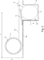
- Fig. 1 illustrates an embodiment of a flooding protection installation 1 which is configured to protect a building 2 (see e.g. Fig. 4 ).
- the installation 1 comprises a membrane 3 connected along a first side edge 4 (see Fig. 7 ) to a float 5 (see Fig. 7 ).
- the membrane 3 is configured to be arranged in a packed configuration at a first distance X (see Fig. 3 ) from the building 2. Furthermore, the membrane 3 is configured to be fixed to the ground 6 at a start location S (see e.g. Fig. 3 ) along a second side edge 7 (see Fig. 7 ).
- the membrane 3 is configured to be unpacked and the float 5 is configured to be moved toward the building 2 by water as indicated by the arrow A in Fig. 3 , whereby a first portion 3A of the membrane is configured to be arranged with a lower surface against ground 6 in an area between the start location S and the building 2.
- the float 5 is further configured to be raised a second distance Y (see Fig. 4 ) along an outer surface of the building 2 and a second portion 3B of the membrane is configured to be arranged with the lower surface against the building 2.
- the flooding protection installation 1 further comprises an encapsulation 8 with space for the membrane 3 in the packed configuration and the float.
- the packed configuration defines a configuration in which the membrane 3 is rolled about the float 5.
- the illustrated embodiment of the encapsulation 8 is arranged with an upper side surface substantially at ground level.
- the encapsulation 8 has an opening 9 and a closure 10 which is movable relative to the opening 8 between an open and closed configuration. To facilitate unpacking of the membrane 3, the encapsulation 8 is arranged so that the opening 9 is facing upwardly.
- the membrane 3 is attached to an inner surface 8A of the encapsulation 8 along the second side edge 7.
- the membrane 3 is attached by use of an adhesive 11.
- the flooding protection installation 1 further comprises a release structure 12 configured to release the membrane 3 upon detection of water to thereby enable unpacking.
- the release structure 12 may comprise a water detection element to provide automatic release.
- the release structure 12 comprises a tube 12 and pressure means (not shown).
- the pressure means inflates the tube 12 whereby the membrane 3 is lifted out of the encapsulation 8 and is arranged in a position which allows water to unpack the membrane 3 and to move the float 5 toward the building.
- the flooding protection installation 1 further comprises a fixing structure (not shown) configured to form a fixing between the encapsulation 8 and a ground surface.
- Fig. 2 illustrates a cross-section of a flooding protection installation 1 where the membrane 3 is arranged in a rolled; i.e. packed configuration in the encapsulation 8.
- the closure 10 is in the closed configuration.
- Fig. 3 illustrates a cross-section of a flooding protection installation 1 being unpacked.
- the closure 10 has been removed by the release structure 12; i.e. the tube 12 has been filled with air to thereby lift the membrane out of the encapsulation 8.
- the membrane 3 has been lifted out of the encapsulation 8, and water is moving the float 5 toward the building 2, whereby the membrane 3 rolls towards the building so that a first portion 3A of the membrane is arranged with a lower surface against ground 6 in an area between the start location S and the building 2.
- the first portion 3A thereby forms a retention portion which is retained on the ground by water on the upper surface.
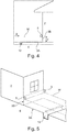
- Figs. 4 and 5 illustrate different views of a flooding protection installation 1 being unpacked.
- the float 5 is moved toward the building 2 by water as indicated by the arrow A, whereby a first portion 3A of the membrane is arranged with a lower surface against ground 6 in an area between the start location S and the building 2.
- the float 5 is further raised a second distance Y along the outer surface of the building 2, whereby a second portion 3B of the membrane is arranged with the lower surface against the building 2.
- Fig. 6 illustrates a flooding protection installation 1 being unpacked where ground level varies around the building 2.
- A the left side of the building 2, ground level is lower than ground level at the right side of the building 2.
- a first portion 3A of the membrane is arranged with a lower surface against ground 6 in an area between the start location S and the building 2.
- a second distance Y where a second portion 3B of the membrane is arranged with the lower surface against the building 2 is smaller at the right side of the building than at the left side of the building.
- Fig. 7 illustrates details of a flooding protection installation 1 before installation
- Fig. 8 illustrates a flooding protection installation 1 adapted to be arranged circumferentially around a building before installation.
- the membrane 3 comprises a plurality of membrane sheets 3' being adhesively joined.
- the float 5 comprises rigid sections 5A connected by bendable sections 5B.
- the bendable sections are arranged at the corner sections of the membrane.
- the membrane 3 is at a first side edge only connected to the rigid sections 5A of the float.
- the membrane 3 comprises corner sections 13 configured to be arranged against a corner of the building by the water. As illustrated in Figs. 7 and 8 , the corner sections 13 are substantially triangular when unpacked.
- the triangular shape facilitates adaptation of the membrane 3 to the shape of the building at corners of the building. In the illustrated embodiment, the triangular shape is obtained by folding parts of the membrane 3. By folding the membrane 3, more membrane material is present at corners of the building thereby ensuring sufficient material to protect the building also at the corners.
- the triangular shape at the corners is obtained by a plurality of folds 14 thereby forming a fan-shape when the membrane 3 is in the unpacked configuration.
- the corner sections 13 each comprises a membrane section being substantially rectangular and comprising a plurality of folds 14 to thereby form a substantially triangular shape, where the folds extend in the unpacking direction (being opposite to the direction Z).
- each corner section is substantially triangular when unpacked.
- the folds 14 are not parallel to each other, as the distance between two neighbouring folds 14 increases from one side edge to the opposite side edge.
- the distance between two neighbouring folds 14 increases from the first side edge to the second side edge.
- the distance between two neighbouring folds 14 increases from second side edge to the first side edge.
- the corner sections 13 are formed of substantially rectangular membrane sections comprising a plurality of folds 14 to thereby form a substantially triangular shape of each of the corner sections in the unpacked configuration.
- the corner sections may comprise a plurality of flexible elongated elements (not shown) arranged transverse to the membrane 3 and extending from the first side edge 4 to the second side edge 7.
- the membrane When preparing the flooding protection installation, the membrane is arranged in the packed configuration by rolling the membrane 3.
- the membrane 3 is rolled around the float 5 from the first side edge 4 toward the second side edge 7 in the direction of the arrows Z.
- Fig. 9 illustrates details of a flooding protection installation 1 before being unpacked; i.e. in a packed configuration
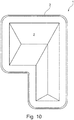
- Fig. 10 illustrates a flooding protection installation 1 in a packed configuration where the membrane 3 is rolled around the float 5 from the first side edge 4 toward the second side edge 7 seen from above. It should be understood that the size of the corner sections 13 relative to the membrane 3 is not to scale, but for illustration only.
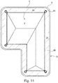
- Fig. 11 illustrates a flooding protection installation 1 in an unpacked configuration.
- the membrane 3 has been lifted out of the encapsulation 8, and the float 5 is moved toward the building 2 by water, whereby a first portion 3A of the membrane is arranged with a lower surface against ground 6 in an area between the start location S and the building 2 with water on the upper side surfaces to retain the membrane at ground.
- the float 5 will further rise a second distance Y along the outer surface of the building 2, whereby a second portion 3B of the membrane will be arranged with the lower surface against the building 2.
Landscapes
- Engineering & Computer Science (AREA)
- Architecture (AREA)
- Structural Engineering (AREA)
- Environmental & Geological Engineering (AREA)
- General Engineering & Computer Science (AREA)
- Civil Engineering (AREA)
- Emergency Management (AREA)
- Business, Economics & Management (AREA)
- Mechanical Engineering (AREA)
- Ocean & Marine Engineering (AREA)
- Buildings Adapted To Withstand Abnormal External Influences (AREA)
- Special Wing (AREA)
- Conveying And Assembling Of Building Elements In Situ (AREA)
- Working Measures On Existing Buildindgs (AREA)
Priority Applications (1)
| Application Number | Priority Date | Filing Date | Title |
|---|---|---|---|
| PL18706436T PL3596287T3 (pl) | 2017-03-17 | 2018-02-08 | Sposób zabezpieczania budynku przed zalaniem wskutek powodzi |
Applications Claiming Priority (2)
| Application Number | Priority Date | Filing Date | Title |
|---|---|---|---|
| DKPA201770188 | 2017-03-17 | ||
| PCT/EP2018/053150 WO2018166724A1 (en) | 2017-03-17 | 2018-02-08 | A method for protecting a building against flooding |
Publications (3)
| Publication Number | Publication Date |
|---|---|
| EP3596287A1 EP3596287A1 (en) | 2020-01-22 |
| EP3596287B1 EP3596287B1 (en) | 2021-04-07 |
| EP3596287B9 true EP3596287B9 (en) | 2021-08-18 |
Family
ID=61256912
Family Applications (1)
| Application Number | Title | Priority Date | Filing Date |
|---|---|---|---|
| EP18706436.5A Active EP3596287B9 (en) | 2017-03-17 | 2018-02-08 | A method for protecting a building against flooding |
Country Status (12)
| Country | Link |
|---|---|
| US (1) | US10900248B2 (pl) |
| EP (1) | EP3596287B9 (pl) |
| JP (1) | JP6998614B2 (pl) |
| CN (1) | CN110651091B (pl) |
| AU (1) | AU2018233490B2 (pl) |
| DK (1) | DK3596287T3 (pl) |
| ES (1) | ES2879832T3 (pl) |
| HU (1) | HUE054837T2 (pl) |
| MY (1) | MY194623A (pl) |
| PL (1) | PL3596287T3 (pl) |
| SG (1) | SG11201908606SA (pl) |
| WO (1) | WO2018166724A1 (pl) |
Families Citing this family (6)
| Publication number | Priority date | Publication date | Assignee | Title |
|---|---|---|---|---|
| US11401678B1 (en) | 2019-08-03 | 2022-08-02 | David Joel Schwartz | Flood protection system |
| CA3121822A1 (en) * | 2020-06-10 | 2021-12-10 | Enhanced Sustainability Inc. | Expandable flood barrier |
| US20230117178A1 (en) * | 2021-03-01 | 2023-04-20 | Drew Berweger | Buoyancy system |
| WO2023158447A1 (en) * | 2022-02-15 | 2023-08-24 | Ghw Solutions, Llc | Systems and methods for flood prevention |
| WO2024054107A1 (en) * | 2022-09-09 | 2024-03-14 | Lye Poh Chai | A flood prevention system |
| JP7698811B1 (ja) * | 2024-12-25 | 2025-06-25 | バンドー化学株式会社 | 浮上袋体フラップゲート及びそれを用いた防水方法 |
Family Cites Families (23)
| Publication number | Priority date | Publication date | Assignee | Title |
|---|---|---|---|---|
| FR2531475A1 (fr) | 1982-08-03 | 1984-02-10 | Pradeau Daniel | Dispositif de protection, notamment d'habitation individuelle, contre les inondations |
| US4488386A (en) * | 1982-11-01 | 1984-12-18 | Thompson William W | Flood shield assembly |
| SE505394C2 (sv) * | 1995-11-14 | 1997-08-18 | Sahbi Belarbi | Översvämningsskydd |
| US6029405A (en) * | 1998-04-23 | 2000-02-29 | Wood; Barbara A. | Apparatus and method for inhibiting water from entering a structure |
| GB2374108A (en) | 2001-03-28 | 2002-10-09 | Geoffrey James Brown | Flood barrier |
| GB2378726A (en) * | 2001-08-14 | 2003-02-19 | Victor Joseph Nock | Inflatable flood prevention structures |
| GB0305110D0 (en) | 2003-03-06 | 2003-04-09 | Nash Robert | Flood protection |
| JP2005029968A (ja) * | 2003-07-07 | 2005-02-03 | Kansai Tech Corp | 防災用ゲート及びゲート構造 |
| JP4322697B2 (ja) * | 2004-02-13 | 2009-09-02 | 功一 高野 | 浸水防止装置 |
| GB2435664B (en) | 2006-03-03 | 2011-05-04 | Meiklewall Scotland Ltd | Barrier apparatus |
| GB2438856B (en) | 2006-06-07 | 2008-06-18 | Peter Dandy | Flood defence system |
| DE102006039194A1 (de) | 2006-08-22 | 2008-02-28 | Schörling Brock GmbH | Hochwasser- und Überflutungsschutzsystem für Gebäude, Stadtteile und Dämme |
| GB2450875A (en) | 2007-07-09 | 2009-01-14 | Meiklewall Scotland Ltd | Flood prevention barrier incorporating a float member |
| DE102007037476A1 (de) * | 2007-08-08 | 2009-04-23 | Adam Gillich | Wasserschutzwall gegen Hochwasser |
| CN201857792U (zh) | 2010-11-23 | 2011-06-08 | 昆明理工大学 | 建筑物防洪浮力装置 |
| CN102011506A (zh) * | 2010-11-23 | 2011-04-13 | 昆明理工大学 | 建筑物防洪浮力装置 |
| JP2013151854A (ja) * | 2011-12-27 | 2013-08-08 | Sawaya:Kk | 浸水防止シート及び家屋等への浸水防止工法 |
| US9085864B2 (en) * | 2012-05-09 | 2015-07-21 | Agapito Ortiz | Flood barrier |
| JP6010507B2 (ja) * | 2013-06-19 | 2016-10-19 | 日立オムロンターミナルソリューションズ株式会社 | 浸水防止装置および自動取引装置 |
| DE102014006783A1 (de) | 2013-12-20 | 2015-06-25 | Armin Hansmann | System zum Schutz eines Gebäudes bei Hochwasser |
| DE102014001431A1 (de) | 2014-01-31 | 2015-08-06 | Henrik Brinkemper | Vorrichtung zum Schutz vor Hochwasser |
| DE102015102792A1 (de) * | 2015-02-26 | 2016-09-01 | Günter Schweizer | System zum Schutz von Objekten gegen Hochwasser |
| JP2016224489A (ja) * | 2015-05-27 | 2016-12-28 | シバタ工業株式会社 | 浸水防止構造体 |
-
2018
- 2018-02-08 CN CN201880028719.2A patent/CN110651091B/zh active Active
- 2018-02-08 ES ES18706436T patent/ES2879832T3/es active Active
- 2018-02-08 MY MYPI2019005362A patent/MY194623A/en unknown
- 2018-02-08 WO PCT/EP2018/053150 patent/WO2018166724A1/en not_active Ceased
- 2018-02-08 HU HUE18706436A patent/HUE054837T2/hu unknown
- 2018-02-08 AU AU2018233490A patent/AU2018233490B2/en active Active
- 2018-02-08 US US16/494,855 patent/US10900248B2/en active Active
- 2018-02-08 DK DK18706436.5T patent/DK3596287T3/da active
- 2018-02-08 SG SG11201908606S patent/SG11201908606SA/en unknown
- 2018-02-08 JP JP2019572282A patent/JP6998614B2/ja active Active
- 2018-02-08 EP EP18706436.5A patent/EP3596287B9/en active Active
- 2018-02-08 PL PL18706436T patent/PL3596287T3/pl unknown
Also Published As
| Publication number | Publication date |
|---|---|
| WO2018166724A1 (en) | 2018-09-20 |
| JP2020513079A (ja) | 2020-04-30 |
| DK3596287T3 (da) | 2021-06-14 |
| JP6998614B2 (ja) | 2022-01-18 |
| EP3596287B1 (en) | 2021-04-07 |
| US20200123800A1 (en) | 2020-04-23 |
| HUE054837T2 (hu) | 2021-10-28 |
| SG11201908606SA (en) | 2019-10-30 |
| MY194623A (en) | 2022-12-07 |
| PL3596287T3 (pl) | 2021-10-25 |
| AU2018233490A1 (en) | 2019-10-17 |
| CN110651091B (zh) | 2021-08-03 |
| US10900248B2 (en) | 2021-01-26 |
| AU2018233490B2 (en) | 2023-07-13 |
| EP3596287A1 (en) | 2020-01-22 |
| CN110651091A (zh) | 2020-01-03 |
| ES2879832T3 (es) | 2021-11-23 |
Similar Documents
| Publication | Publication Date | Title |
|---|---|---|
| EP3596287B9 (en) | A method for protecting a building against flooding | |
| US6216399B1 (en) | Flood protection device | |
| AU2013254286B2 (en) | Flood protection system | |
| EP3292248B1 (en) | Rapid deployment flood barrier | |
| ES2708868T3 (es) | Método, revestimiento impermeable al agua y paneles impermeables al agua para instalación en depósitos y canales | |
| US7214005B1 (en) | Sectionalized flood control barrier | |
| WO2002040780A1 (en) | Hydraulic dam | |
| US4171174A (en) | System for depositing and protecting sand and other littoral draft material | |
| WO2010028959A1 (en) | Sealing of canals | |
| CN107780443B (zh) | 一种垂直防渗专用gcl复合构件及其铺设方法 | |
| ES2671033T3 (es) | Método y sistema para anclar un revestimiento de impermeabilización a los bordes de hormigón de una estructura hidráulica | |
| GB2451286A (en) | Inflatable flood defence system | |
| EP2561142B1 (en) | Oil boom | |
| US7635238B2 (en) | Device for preventing dock piling or structure piling uplift | |
| US7300228B2 (en) | Method and apparatus for preventing dock or structure piling uplift | |
| JP7698811B1 (ja) | 浮上袋体フラップゲート及びそれを用いた防水方法 | |
| JPH0786242B2 (ja) | 地下室浮上防止装置及び同装置用遮水袋 | |
| US20250334096A1 (en) | Wave energy converter | |
| ES2343990B1 (es) | Cubierta flotante adaptable al nivel del embalse. | |
| AU2012258446A1 (en) | A barrier | |
| AU2003268859A1 (en) | Water conservation | |
| JP2009264083A (ja) | 高潮を阻止する構造物 | |
| GB2551607A (en) | Flood defence | |
| PL223490B1 (pl) | Zapora przeciwpowodziowa | |
| AU2008202511A1 (en) | Grain bunker covering system |
Legal Events
| Date | Code | Title | Description |
|---|---|---|---|
| STAA | Information on the status of an ep patent application or granted ep patent |
Free format text: STATUS: UNKNOWN |
|
| STAA | Information on the status of an ep patent application or granted ep patent |
Free format text: STATUS: THE INTERNATIONAL PUBLICATION HAS BEEN MADE |
|
| PUAI | Public reference made under article 153(3) epc to a published international application that has entered the european phase |
Free format text: ORIGINAL CODE: 0009012 |
|
| STAA | Information on the status of an ep patent application or granted ep patent |
Free format text: STATUS: REQUEST FOR EXAMINATION WAS MADE |
|
| 17P | Request for examination filed |
Effective date: 20191017 |
|
| AK | Designated contracting states |
Kind code of ref document: A1 Designated state(s): AL AT BE BG CH CY CZ DE DK EE ES FI FR GB GR HR HU IE IS IT LI LT LU LV MC MK MT NL NO PL PT RO RS SE SI SK SM TR |
|
| AX | Request for extension of the european patent |
Extension state: ME |
|
| GRAP | Despatch of communication of intention to grant a patent |
Free format text: ORIGINAL CODE: EPIDOSNIGR1 |
|
| STAA | Information on the status of an ep patent application or granted ep patent |
Free format text: STATUS: GRANT OF PATENT IS INTENDED |
|
| INTG | Intention to grant announced |
Effective date: 20200909 |
|
| GRAS | Grant fee paid |
Free format text: ORIGINAL CODE: EPIDOSNIGR3 |
|
| GRAA | (expected) grant |
Free format text: ORIGINAL CODE: 0009210 |
|
| STAA | Information on the status of an ep patent application or granted ep patent |
Free format text: STATUS: THE PATENT HAS BEEN GRANTED |
|
| AK | Designated contracting states |
Kind code of ref document: B1 Designated state(s): AL AT BE BG CH CY CZ DE DK EE ES FI FR GB GR HR HU IE IS IT LI LT LU LV MC MK MT NL NO PL PT RO RS SE SI SK SM TR |
|
| AX | Request for extension of the european patent |
Extension state: ME |
|
| REG | Reference to a national code |
Ref country code: GB Ref legal event code: FG4D |
|
| REG | Reference to a national code |
Ref country code: CH Ref legal event code: EP Ref country code: AT Ref legal event code: REF Ref document number: 1379879 Country of ref document: AT Kind code of ref document: T Effective date: 20210415 |
|
| REG | Reference to a national code |
Ref country code: DE Ref legal event code: R096 Ref document number: 602018015170 Country of ref document: DE |
|
| REG | Reference to a national code |
Ref country code: IE Ref legal event code: FG4D |
|
| REG | Reference to a national code |
Ref country code: DK Ref legal event code: T3 Effective date: 20210607 |
|
| REG | Reference to a national code |
Ref country code: NL Ref legal event code: FP |
|
| REG | Reference to a national code |
Ref country code: LT Ref legal event code: MG9D |
|
| REG | Reference to a national code |
Ref country code: CH Ref legal event code: PK Free format text: BERICHTIGUNG B9 |
|
| REG | Reference to a national code |
Ref country code: HU Ref legal event code: AG4A Ref document number: E054837 Country of ref document: HU |
|
| PG25 | Lapsed in a contracting state [announced via postgrant information from national office to epo] |
Ref country code: HR Free format text: LAPSE BECAUSE OF FAILURE TO SUBMIT A TRANSLATION OF THE DESCRIPTION OR TO PAY THE FEE WITHIN THE PRESCRIBED TIME-LIMIT Effective date: 20210407 Ref country code: LT Free format text: LAPSE BECAUSE OF FAILURE TO SUBMIT A TRANSLATION OF THE DESCRIPTION OR TO PAY THE FEE WITHIN THE PRESCRIBED TIME-LIMIT Effective date: 20210407 Ref country code: FI Free format text: LAPSE BECAUSE OF FAILURE TO SUBMIT A TRANSLATION OF THE DESCRIPTION OR TO PAY THE FEE WITHIN THE PRESCRIBED TIME-LIMIT Effective date: 20210407 Ref country code: BG Free format text: LAPSE BECAUSE OF FAILURE TO SUBMIT A TRANSLATION OF THE DESCRIPTION OR TO PAY THE FEE WITHIN THE PRESCRIBED TIME-LIMIT Effective date: 20210707 |
|
| REG | Reference to a national code |
Ref country code: ES Ref legal event code: FG2A Ref document number: 2879832 Country of ref document: ES Kind code of ref document: T3 Effective date: 20211123 |
|
| PG25 | Lapsed in a contracting state [announced via postgrant information from national office to epo] |
Ref country code: IS Free format text: LAPSE BECAUSE OF FAILURE TO SUBMIT A TRANSLATION OF THE DESCRIPTION OR TO PAY THE FEE WITHIN THE PRESCRIBED TIME-LIMIT Effective date: 20210807 Ref country code: GR Free format text: LAPSE BECAUSE OF FAILURE TO SUBMIT A TRANSLATION OF THE DESCRIPTION OR TO PAY THE FEE WITHIN THE PRESCRIBED TIME-LIMIT Effective date: 20210708 Ref country code: LV Free format text: LAPSE BECAUSE OF FAILURE TO SUBMIT A TRANSLATION OF THE DESCRIPTION OR TO PAY THE FEE WITHIN THE PRESCRIBED TIME-LIMIT Effective date: 20210407 Ref country code: NO Free format text: LAPSE BECAUSE OF FAILURE TO SUBMIT A TRANSLATION OF THE DESCRIPTION OR TO PAY THE FEE WITHIN THE PRESCRIBED TIME-LIMIT Effective date: 20210707 Ref country code: PT Free format text: LAPSE BECAUSE OF FAILURE TO SUBMIT A TRANSLATION OF THE DESCRIPTION OR TO PAY THE FEE WITHIN THE PRESCRIBED TIME-LIMIT Effective date: 20210809 Ref country code: RS Free format text: LAPSE BECAUSE OF FAILURE TO SUBMIT A TRANSLATION OF THE DESCRIPTION OR TO PAY THE FEE WITHIN THE PRESCRIBED TIME-LIMIT Effective date: 20210407 Ref country code: SE Free format text: LAPSE BECAUSE OF FAILURE TO SUBMIT A TRANSLATION OF THE DESCRIPTION OR TO PAY THE FEE WITHIN THE PRESCRIBED TIME-LIMIT Effective date: 20210407 |
|
| REG | Reference to a national code |
Ref country code: DE Ref legal event code: R097 Ref document number: 602018015170 Country of ref document: DE |
|
| PG25 | Lapsed in a contracting state [announced via postgrant information from national office to epo] |
Ref country code: SM Free format text: LAPSE BECAUSE OF FAILURE TO SUBMIT A TRANSLATION OF THE DESCRIPTION OR TO PAY THE FEE WITHIN THE PRESCRIBED TIME-LIMIT Effective date: 20210407 Ref country code: SK Free format text: LAPSE BECAUSE OF FAILURE TO SUBMIT A TRANSLATION OF THE DESCRIPTION OR TO PAY THE FEE WITHIN THE PRESCRIBED TIME-LIMIT Effective date: 20210407 Ref country code: EE Free format text: LAPSE BECAUSE OF FAILURE TO SUBMIT A TRANSLATION OF THE DESCRIPTION OR TO PAY THE FEE WITHIN THE PRESCRIBED TIME-LIMIT Effective date: 20210407 Ref country code: RO Free format text: LAPSE BECAUSE OF FAILURE TO SUBMIT A TRANSLATION OF THE DESCRIPTION OR TO PAY THE FEE WITHIN THE PRESCRIBED TIME-LIMIT Effective date: 20210407 Ref country code: CZ Free format text: LAPSE BECAUSE OF FAILURE TO SUBMIT A TRANSLATION OF THE DESCRIPTION OR TO PAY THE FEE WITHIN THE PRESCRIBED TIME-LIMIT Effective date: 20210407 |
|
| PLBE | No opposition filed within time limit |
Free format text: ORIGINAL CODE: 0009261 |
|
| STAA | Information on the status of an ep patent application or granted ep patent |
Free format text: STATUS: NO OPPOSITION FILED WITHIN TIME LIMIT |
|
| 26N | No opposition filed |
Effective date: 20220110 |
|
| PG25 | Lapsed in a contracting state [announced via postgrant information from national office to epo] |
Ref country code: IS Free format text: LAPSE BECAUSE OF FAILURE TO SUBMIT A TRANSLATION OF THE DESCRIPTION OR TO PAY THE FEE WITHIN THE PRESCRIBED TIME-LIMIT Effective date: 20210807 Ref country code: AL Free format text: LAPSE BECAUSE OF FAILURE TO SUBMIT A TRANSLATION OF THE DESCRIPTION OR TO PAY THE FEE WITHIN THE PRESCRIBED TIME-LIMIT Effective date: 20210407 |
|
| PG25 | Lapsed in a contracting state [announced via postgrant information from national office to epo] |
Ref country code: MC Free format text: LAPSE BECAUSE OF FAILURE TO SUBMIT A TRANSLATION OF THE DESCRIPTION OR TO PAY THE FEE WITHIN THE PRESCRIBED TIME-LIMIT Effective date: 20210407 |
|
| P01 | Opt-out of the competence of the unified patent court (upc) registered |
Effective date: 20230516 |
|
| PG25 | Lapsed in a contracting state [announced via postgrant information from national office to epo] |
Ref country code: MK Free format text: LAPSE BECAUSE OF FAILURE TO SUBMIT A TRANSLATION OF THE DESCRIPTION OR TO PAY THE FEE WITHIN THE PRESCRIBED TIME-LIMIT Effective date: 20210407 Ref country code: CY Free format text: LAPSE BECAUSE OF FAILURE TO SUBMIT A TRANSLATION OF THE DESCRIPTION OR TO PAY THE FEE WITHIN THE PRESCRIBED TIME-LIMIT Effective date: 20210407 |
|
| PG25 | Lapsed in a contracting state [announced via postgrant information from national office to epo] |
Ref country code: MT Free format text: LAPSE BECAUSE OF FAILURE TO SUBMIT A TRANSLATION OF THE DESCRIPTION OR TO PAY THE FEE WITHIN THE PRESCRIBED TIME-LIMIT Effective date: 20210407 |
|
| PGFP | Annual fee paid to national office [announced via postgrant information from national office to epo] |
Ref country code: CH Payment date: 20250301 Year of fee payment: 8 |
|
| PGFP | Annual fee paid to national office [announced via postgrant information from national office to epo] |
Ref country code: PL Payment date: 20250127 Year of fee payment: 8 |
|
| PG25 | Lapsed in a contracting state [announced via postgrant information from national office to epo] |
Ref country code: TR Free format text: LAPSE BECAUSE OF FAILURE TO SUBMIT A TRANSLATION OF THE DESCRIPTION OR TO PAY THE FEE WITHIN THE PRESCRIBED TIME-LIMIT Effective date: 20210407 |
|
| REG | Reference to a national code |
Ref country code: CH Ref legal event code: U11 Free format text: ST27 STATUS EVENT CODE: U-0-0-U10-U11 (AS PROVIDED BY THE NATIONAL OFFICE) Effective date: 20260301 |
|
| PGFP | Annual fee paid to national office [announced via postgrant information from national office to epo] |
Ref country code: LU Payment date: 20260216 Year of fee payment: 9 Ref country code: NL Payment date: 20260217 Year of fee payment: 9 |
|
| PGFP | Annual fee paid to national office [announced via postgrant information from national office to epo] |
Ref country code: HU Payment date: 20260123 Year of fee payment: 9 |
|
| PGFP | Annual fee paid to national office [announced via postgrant information from national office to epo] |
Ref country code: GB Payment date: 20260217 Year of fee payment: 9 |
|
| PGFP | Annual fee paid to national office [announced via postgrant information from national office to epo] |
Ref country code: ES Payment date: 20260303 Year of fee payment: 9 |
|
| PGFP | Annual fee paid to national office [announced via postgrant information from national office to epo] |
Ref country code: DE Payment date: 20260217 Year of fee payment: 9 Ref country code: DK Payment date: 20260218 Year of fee payment: 9 Ref country code: IE Payment date: 20260216 Year of fee payment: 9 |
|
| PGFP | Annual fee paid to national office [announced via postgrant information from national office to epo] |
Ref country code: AT Payment date: 20260217 Year of fee payment: 9 |
|
| PGFP | Annual fee paid to national office [announced via postgrant information from national office to epo] |
Ref country code: BE Payment date: 20260216 Year of fee payment: 9 Ref country code: IT Payment date: 20260223 Year of fee payment: 9 |
|
| PGFP | Annual fee paid to national office [announced via postgrant information from national office to epo] |
Ref country code: FR Payment date: 20260217 Year of fee payment: 9 |