EP3612002A1 - Verfahren zur ansteuerung einer heizeinrichtung eines kochfelds und kochfeld - Google Patents
Verfahren zur ansteuerung einer heizeinrichtung eines kochfelds und kochfeld Download PDFInfo
- Publication number
- EP3612002A1 EP3612002A1 EP19188304.0A EP19188304A EP3612002A1 EP 3612002 A1 EP3612002 A1 EP 3612002A1 EP 19188304 A EP19188304 A EP 19188304A EP 3612002 A1 EP3612002 A1 EP 3612002A1
- Authority
- EP
- European Patent Office
- Prior art keywords
- power
- cooking vessel
- decision time
- operator
- heating
- Prior art date
- Legal status (The legal status is an assumption and is not a legal conclusion. Google has not performed a legal analysis and makes no representation as to the accuracy of the status listed.)
- Granted
Links
Images


Classifications
-
- H—ELECTRICITY
- H05—ELECTRIC TECHNIQUES NOT OTHERWISE PROVIDED FOR
- H05B—ELECTRIC HEATING; ELECTRIC LIGHT SOURCES NOT OTHERWISE PROVIDED FOR; CIRCUIT ARRANGEMENTS FOR ELECTRIC LIGHT SOURCES, IN GENERAL
- H05B6/00—Heating by electric, magnetic or electromagnetic fields
- H05B6/02—Induction heating
- H05B6/06—Control, e.g. of temperature, of power
- H05B6/062—Control, e.g. of temperature, of power for cooking plates or the like
- H05B6/065—Control, e.g. of temperature, of power for cooking plates or the like using coordinated control of multiple induction coils
-
- H—ELECTRICITY
- H05—ELECTRIC TECHNIQUES NOT OTHERWISE PROVIDED FOR
- H05B—ELECTRIC HEATING; ELECTRIC LIGHT SOURCES NOT OTHERWISE PROVIDED FOR; CIRCUIT ARRANGEMENTS FOR ELECTRIC LIGHT SOURCES, IN GENERAL
- H05B6/00—Heating by electric, magnetic or electromagnetic fields
- H05B6/02—Induction heating
- H05B6/06—Control, e.g. of temperature, of power
- H05B6/062—Control, e.g. of temperature, of power for cooking plates or the like
-
- H—ELECTRICITY
- H05—ELECTRIC TECHNIQUES NOT OTHERWISE PROVIDED FOR
- H05B—ELECTRIC HEATING; ELECTRIC LIGHT SOURCES NOT OTHERWISE PROVIDED FOR; CIRCUIT ARRANGEMENTS FOR ELECTRIC LIGHT SOURCES, IN GENERAL
- H05B6/00—Heating by electric, magnetic or electromagnetic fields
- H05B6/02—Induction heating
- H05B6/10—Induction heating apparatus, other than furnaces, for specific applications
- H05B6/12—Cooking devices
- H05B6/1209—Cooking devices induction cooking plates or the like and devices to be used in combination with them
-
- H—ELECTRICITY
- H05—ELECTRIC TECHNIQUES NOT OTHERWISE PROVIDED FOR
- H05B—ELECTRIC HEATING; ELECTRIC LIGHT SOURCES NOT OTHERWISE PROVIDED FOR; CIRCUIT ARRANGEMENTS FOR ELECTRIC LIGHT SOURCES, IN GENERAL
- H05B2213/00—Aspects relating both to resistive heating and to induction heating, covered by H05B3/00 and H05B6/00
- H05B2213/03—Heating plates made out of a matrix of heating elements that can define heating areas adapted to cookware randomly placed on the heating plate
-
- H—ELECTRICITY
- H05—ELECTRIC TECHNIQUES NOT OTHERWISE PROVIDED FOR
- H05B—ELECTRIC HEATING; ELECTRIC LIGHT SOURCES NOT OTHERWISE PROVIDED FOR; CIRCUIT ARRANGEMENTS FOR ELECTRIC LIGHT SOURCES, IN GENERAL
- H05B2213/00—Aspects relating both to resistive heating and to induction heating, covered by H05B3/00 and H05B6/00
- H05B2213/05—Heating plates with pan detection means
-
- H—ELECTRICITY
- H05—ELECTRIC TECHNIQUES NOT OTHERWISE PROVIDED FOR
- H05B—ELECTRIC HEATING; ELECTRIC LIGHT SOURCES NOT OTHERWISE PROVIDED FOR; CIRCUIT ARRANGEMENTS FOR ELECTRIC LIGHT SOURCES, IN GENERAL
- H05B2213/00—Aspects relating both to resistive heating and to induction heating, covered by H05B3/00 and H05B6/00
- H05B2213/07—Heating plates with temperature control means
Definitions
- the invention relates to a method for controlling a heating device of a cooktop and a corresponding cooktop.
- the cooktop has a plurality of heating devices under a cooktop plate and pan detection means in order to recognize a position of a cooking vessel on the cooktop plate.
- the invention has for its object to provide an initially mentioned method and an above-mentioned cooktop with which problems of the prior art can be avoided and in particular it is possible to control the cooktop in a practical and advantageous manner or to enable convenient use, in particular when moving a cooking vessel.
- the hob which can be operated with the method according to the invention and which is designed to carry it out, has a hob plate and at least two heating devices under the hob plate.
- These are advantageous induction heating coils, which can be operated individually or together, in order to be able to heat an erected cooking vessel.
- the hob has pan detection means in order to be able to recognize a position of a cooking vessel on the hob plate.
- These pot detection means can be generally designed, for example formed by the aforementioned induction heating coils themselves or by additional sensor coils, for example according to the DE 10 2014 224 051 A1 , Alternatively, a camera or the like. be arranged above the cooktop and optically record the state or processes on the cooktop.
- the cooktop also has an operating device with control elements and at least one display and a controller for the cooktop.
- the method according to the invention can be carried out particularly well with such a hob.
- a cooking vessel is set up over a first heating device of the hob, possibly also over a plurality of heating devices or over a plurality of heating elements, which together can form a heating device corresponding to the cooking vessel.
- This heating device heats it with a relatively high first power, this relatively high first power being at least 50% of the permanently maximum possible power of the first heating device, ie at least 50% of a permanent nominal power.
- This is particularly important in the case of induction heating coils, which can also be operated in a so-called boost mode with a higher output than this nominal continuous output, for example up to 50% higher. With this power, they can only be operated for a few minutes.
- the relatively high first power mentioned can also be such a boost power.
- the first output mentioned is even at least 70% of the permanently maximum possible output. For cooking levels, this can be from level 8.
- the cooking vessel is moved by at least 4 cm, possibly also so far that it no longer covers this first heating device.
- This shifting is recognized by a control of the hob, advantageously with the aid of the aforementioned pan detection means.
- the cooking vessel is heated with a second power, this second power being reduced compared to the first power.
- This second output is advantageously at least 10% to 50% lower than the first output.
- a counter begins to count a predetermined decision time.
- This counting is signaled to an operator optically and / or acoustically as a process so that they can see it clearly.
- Counting down a time is advantageously indicated optically as a countdown.
- the operator does not react during the decision time, which in this case means that he does not change the heating output for this cooking vessel or on the previous first heating device or a new heating device which is now covered by the cooking vessel due to the displacement , It can therefore be provided that the operator makes an operating input for other cooking vessels or other cooking points formed for the cooking vessels, which should not count for the displaced cooking vessel.
- the operator reacts during the decision time and changes the performance, advantageously into a third performance.
- This third power is particularly advantageous compared to the first power, but this need not necessarily be the case. It can be at least 10% to 50% lower.
- the cooking vessel is heated again permanently with the first power after the decision time has expired, this advantageously taking place in such a way that the cooking vessel is heated again in absolute terms with the same power as previously corresponding to the first power. It does not matter whether this is done by a single heating device or by several, especially in the case of induction heating coils.
- the cooking vessel is permanently heated with the changed power after the power has changed, in particular to the third power mentioned, or after the decision time has expired, that is to say either immediately or only after the decision time has expired. This is preferred with the third service.
- This shifting also has the advantage that the cooking vessel is then not only no longer or only slightly above the previously heating heating device, but also stands with a certain probability additionally on a cold area of the hob plate. This makes it a bit cooler, so that the water stops boiling relatively quickly, which corresponds to this instinctive reaction of the operator.
- the goal can be achieved here that the water in the cooking vessel stops boiling or boiling over as quickly as possible.
- the operator wants the water to actually continue to boil, this is done automatically after the decision time has elapsed, for example after a few seconds. The operator then no longer has to do anything about this, he may be able to remove a lid from the cooking vessel, which also reliably prevents boiling over.
- an operator can be informed with the invention on the one hand about the change or reduction in performance. At the same time, she is asked to do so or has it in her hand to make the service valid again without intervention. Alternatively, it can determine the power setting through direct intervention.
- the minimum displacement mentioned can advantageously be greater than 4 cm, particularly advantageously greater than 10 cm. This means that a very slight displacement of the cooking vessel, for example by 1 cm to 4 cm, which can also happen unintentionally, should have no effect and the cooking vessel is then heated as before, without intervention by a control of the hob. A direction of displacement can generally be neglected. It can thus be taken into account that several cooking vessels can stand on the hob when in use and a shift is not always possible or takes place to the rear, which is probably the most common and simplest case, but may also have to be carried out diagonally to the rear, possibly also to the front.
- the method is particularly advantageous when the cooking vessel is clearly displaced such that the cooking vessel is completely removed from the first heating device and is moved over at least one second heating device. At this point, the cooking vessel should then be heated with the second power by at least the second heating device, at least for the decision time.
- a third case can also be provided in the invention, namely that the operator reacts during the decision time, that is to say before it expires, and actuates an operating element.
- This can advantageously be a specific control element provided for this purpose. Then the decision time is aborted immediately, so it is no longer counted. Furthermore, the cooking vessel is then immediately heated again with the original first output. This covers the aforementioned option that the operator wants the cooking vessel to continue to be heated at the first power. Furthermore, in this third case, the possibility is also to be covered that the operator moves the cooking vessel back to the original position, that is to say shifts the cooking vessel again, so to speak.
- the second power is reduced by approximately 25% to 40% compared to the first power.
- it is not quite as much reduced, but still so strong, for example, to briefly interrupt a boiling process of water in the cooking vessel and thus to avoid boiling over.
- the aforementioned relatively high power is a surface power density of more than 3.5 W / cm 2 . It can also be more than 5 W / cm 2 or even more than 7 W / cm 2 , corresponding to a level 8 or 9 as a power level or cooking level.
- a visual display of the counting as the decision time has elapsed can also be done with a flashing.
- a aforementioned number or a progress bar can flash, which ensures particularly well that the operator notices this.
- the operator reacts during the decision time and, by actuating an operating element, in particular a specially provided operating element, permanently adjusts the output to the second output in order to further heat the cooking vessel ,
- an operating element in particular a specially provided operating element, permanently adjusts the output to the second output in order to further heat the cooking vessel .
- the operator can set the second service as a permanent additional service even before the decision time has expired, for example because the operator considers this service to be advantageous.
- the power currently used for heating the cooking vessel is displayed as a number or as a power indicator. This then advantageously corresponds to a power level. This means that the operator always knows at a glance how strongly the cooking vessel is being heated at all times.
- a heating device can be understood in the context of the invention in such a way that it does not have only a single heating element.
- two to four induction heating coils can be used together to heat a single cooking vessel and can then be viewed as a heating device with the same power, at least the same area power and / or absolute power.
- a hob with which the above-described method can advantageously be carried out advantageously has more than the usual four or six heating devices for four or six discrete hotplates. For example, at least two times three or two times four heating devices can be provided, in particular three times four heating devices. Their arrangement should be regular so that the cooktop is well covered.
- FIG. 1 a top view of an induction hob 11 according to the invention for carrying out the method according to the invention, which has a hob plate 12, is shown.
- the rear and by far the largest part of the cooktop plate 12 forms a heating area 13 in order to be able to use it to heat cooking vessels or pots that have been set up.
- Eight induction heating coils 15 are arranged below the heating region 13, here denoted by HE10 to HE23.
- the left half of the heating area 13 has four induction heating coils 15 and the right half also. However, this division is not absolutely necessary; fewer and, above all, even more induction heating coils could be provided for the entire heating area 13.
- a pot T1 as a cooking vessel is placed on the induction hob 11 at the front left. It largely covers the front left induction heating coils HE10. On the right a larger oval pot T2 is set up as a cooking vessel corresponding to a roasting pan, approximately in the middle between the two induction heating coils HE20 and HE23 and on top of them.
- the induction hob 11 has an operating device 17, advantageously arranged below the same hob plate 12 and realized with touch switches, advantageously with capacitive sensor elements and light indicators or LEDs.
- the operating device 17 has four horizontally running so-called sliders 19a to 19d in a special distribution, which does not play a significant role here.
- Each slider has ten light segments 20, a separate sensor element also being provided on each light segment 20.
- Such a slider 19 is thus a type of illuminated touch strip.
- a display 21 is arranged to the right of each slider 19, so four displays 21a to 21d are also provided.
- the displays 21 each have two seven-segment displays for representing corresponding numbers and letters or symbols, as shown in the following 2 to 4 is easy to see.
- the target power with the power level 8 is set on the lower left slider 19a.
- the power setting or power setting in stages is usual for hobs. This can be done by wiping a finger above the slider 19a, alternatively via direct operation. If a finger is placed on the slider 19a from the right over the second light segment 20a, which is the ninth light segment when seen from the left, the power level 8 can also be set directly. In any case, the display 21a with the right digit indicates the power level 8 by lighting, advantageously by constant lighting.
- the eight left light segments 20a light up and thus also illustrate the set high power level as the target power for the pot T1.
- the setting up of the pots T1 and T2 may have been recognized by the induction heating coils HE themselves. Alternatively, other sensors may have detected it.
- the power level 8 corresponds to an area power density of approximately 5 W / cm 2 for the pot T1. So this first achievement is a great achievement. If the first performance were significantly smaller than 3.5 W / cm 2 or less than 3 W / cm 2 or less than a power level of "7" or "6" or below, the method according to the invention would not be used, and in particular no reduction in the power in the new one second position.
- a target power can be set for the right pot T2 and displayed on the slider 19d and on the display 21a.
- the pot T1 is pushed back by the operator into the new second position T1 '. This should serve as a quick reaction to the fact that the water in the pot T1 threatens to boil over or is already boiling over something that is not desired by the operator. Moving the pot T1 is then at least subjectively or intuitively faster and more direct and reliable for many operators than is the reduction of the power by means of the operating device.
- this position of the pot T1' is recognized again position T1 as before. If the distance d were smaller than the minimum displacement mentioned at the beginning, no action would take place.
- the pot T1 ' is operated with reduced power as a new second power.
- the performance is reduced, and significantly.
- the display 21a shows the power level 4 with the right digit.
- a predetermined decision time begins or is counted down on a counter in the aforementioned control of the induction hob 11. It is advantageously chosen to be 10 seconds. The course of this decision time should be visually displayed to an operator, this is in the Fig. 4 clarified. On the left it is shown how only ten of these light segments on a slider 19 with the ten light segments 20 shine, as shown at the very top. Then only nine light segments light up, then eight light segments 20, etc. Another light segment is advantageously deleted per second, so that the decision time is optically counted down.
- the numerical counting of the decision time can be shown on the display 21 with the seven-segment displays as a kind of countdown. At the very bottom, if the light segment 20 no longer lights up in the slider 19 shown on the left, a "0" would light up accordingly on the right.
- the reduction in power can be shown on the display 21, for example by a letter such as a "U”.
- the reduced second power can be shown on the display 21, ie the number 4 accordingly Fig. 3 , as the actually used power.
- the decision time is advantageously optically counted on the slider 19.
- the expiration of the decision time can according to the Fig. 4 are also represented by flashing on the slider 19 or on its light segments 20 and / or on the display 21.
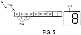
- the operator can now react as previously described. If it does not react at all within the decision time, the pot T1 'in the new position is operated again immediately after the decision time has elapsed with the original first power, that is with power level 8. This is shown in FIG. 6.
- the operator reacts during the decision time of 10 seconds and changes the power with a control element or with the slider 19, which is still active despite displaying the expiry of the decision time, into a third power.
- This third benefit may be reduced compared to the first, but need not be.
- the third service can also correspond to the second service.
- the pot T1 'in the new position is heated permanently with this third power immediately after changing to the third power. Alternatively, this can only take place after the decision time has expired, but this is considered disadvantageous.
- the operator reacts while counting the decision time, he can operate an operating element in the third case mentioned, advantageously a certain operating element provided for this purpose. This causes the decision time to be aborted immediately and the decision time to be counted, and the pot T1 'is then immediately heated again with the first output.
- the operator also reacts while counting the decision time and actuates an operating element, advantageously a specially provided operating element.
- an operating element advantageously a specially provided operating element.
- she can permanently set the power to the second power for heating the pot T1 ', for example because she has seen that this corresponds to the desire to heat the pot T1' in the new position.
- the pot T2 as described above when it is moved to the new position T2 '. It covers two induction heating coils in both positions, once as pot T2 the induction heating coils HE20 and HE23 and as pot T2 'in the shifted position the induction heating coils HE21 and HE22.
- the pot is heated with a correspondingly high first output, the output is first reduced after moving by the distance d.
- the two induction heating coils are treated as one. It would also be the case if a pot were moved from two induction heating coils to a single one, or if a pot was moved from previously one induction heating coil to two.
- absolute power or a power level it should change for the pot as described above, regardless of the number of induction heating coils required. This applies at least as long as the desired service can be provided.
Landscapes
- Physics & Mathematics (AREA)
- Electromagnetism (AREA)
- Induction Heating Cooking Devices (AREA)
- Electric Stoves And Ranges (AREA)
Abstract
Description
- Die Erfindung betrifft ein Verfahren zur Ansteuerung einer Heizeinrichtung eines Kochfelds sowie ein entsprechendes Kochfeld. Das Kochfeld weist mehrere Heizeinrichtungen unter einer Kochfeldplatte auf sowie Topferkennungsmittel, um eine Position eines Kochgefäßes auf der Kochfeldplatte zu erkennen.
- Aus der
EP 2211591 A1 ist es bekannt, dass bei einem Induktionskochfeld mit einer Vielzahl von Induktionsheizspulen als Heizeinrichtungen unter einer Kochfeldplatte diejenigen Induktionsheizspulen das Beheizen eines aufgestellten Kochgefäßes bzw. seines Inhalts übernehmen, die von dem Kochgefäß vollständig oder zumindest zu 50 % überdeckt sind. Wird das Kochgefäß bewegt, beispielsweise bewusst in eine neue Position, beispielsweise weil mehr Platz auf der Kochfeldplatte benötigt wird bzw. das Kochgefäß an dieser Stelle stört, so wird eine vorherige Leistungsstufe als vorgegebene erste Flächenleistungsdichte zum Beheizen des Kochgefäßes sozusagen mitgenommen. Das verschobene Kochgefäß wird auch in der neuen Position mit dieser vorgegebenen ersten Flächenleistungsdichte beheizt. Somit wird einer Bedienperson der Aufwand für das erneute Eingeben der vorherigen Leistungsstufe bzw. Flächenleistungsdichte für das Kochgefäß an seiner neuen Position erspart. - Der Erfindung liegt die Aufgabe zugrunde, ein eingangs genanntes Verfahren sowie ein eingangs genanntes Kochfeld zu schaffen, mit denen Probleme des Stands der Technik vermieden werden können und es insbesondere möglich ist, das Kochfeld praxistauglich und vorteilhaft anzusteuern bzw. eine komfortable Nutzung zu ermöglichen, insbesondere bei Verschieben eines Kochgefäßes.
- Gelöst wird diese Aufgabe durch ein Verfahren mit den Merkmalen des Anspruchs 1 sowie durch ein Kochfeld mit den Merkmalen des Anspruchs 14. Vorteilhafte sowie bevorzugte Ausgestaltungen der Erfindung sind Gegenstand der weiteren Ansprüche und werden im Folgenden näher erläutert. Dabei werden manche der Merkmale nur für das Verfahren oder nur für das Kochfeld beschrieben. Sie sollen jedoch unabhängig davon sowohl für das Verfahren als auch für das Kochfeld selbständig und unabhängig voneinander gelten können. Der Wortlaut der Ansprüche wird durch ausdrückliche Bezugnahme zum Inhalt der Beschreibung gemacht.
- Das Kochfeld, das mit dem erfindungsgemäßen Verfahren betrieben werden kann und das zu dessen Ausführung ausgebildet ist, weist eine Kochfeldplatte und mindestens zwei Heizeinrichtungen unter der Kochfeldplatte auf. Vorteilhaft sind dies Induktionsheizspulen, die einzeln oder gemeinsam betrieben werden können, um ein aufgestelltes Kochgefäß beheizen zu können. Des Weiteren weist das Kochfeld Topferkennungsmittel auf, um eine Position eines Kochgefäßes auf der Kochfeldplatte erkennen zu können. Diese Topferkennungsmittel können allgemein ausgebildet sein, beispielsweise durch die genannten Induktionsheizspulen selbst gebildet sein oder durch zusätzliche Sensorspulen beispielsweise gemäß der
DE 10 2014 224 051 A1 . Alternativ kann eine Kamera odgl. über dem Kochfeld angeordnet sein und den Zustand bzw. Vorgänge auf dem Kochfeld optisch erfassen. Schließlich weist das Kochfeld noch eine Bedieneinrichtung mit Bedienelementen und mindestens einer Anzeige sowie eine Steuerung für das Kochfeld auf. - Mit einem solchen Kochfeld kann das erfindungsgemäße Verfahren besonders gut durchgeführt werden. Bei diesem Verfahren wird ein Kochgefäß über eine erste Heizeinrichtung des Kochfelds aufgestellt, möglicherweise auch über mehrere Heizeinrichtungen bzw. über mehrere Heizelemente, die gemeinsam eine Heizeinrichtung bilden können entsprechend dem Kochgefäß. Von dieser Heizeinrichtung wird es mit einer relativ hohen ersten Leistung beheizt, wobei diese relativ hohe erste Leistung mindestens 50 % der dauerhaft maximal möglichen Leistung der ersten Heizeinrichtung beträgt, also mindestens 50 % einer Dauer-Nennleistung. Dies ist vor allem im Fall von Induktionsheizspulen von Bedeutung, die in einem sogenannten Boost-Betrieb auch mit über diese Nenn-Dauerleistung erhöhter Leistung betrieben werden können, beispielsweise mit bis zu 50 % darüber. Mit dieser Leistung können sie aber nur einige wenige Minuten lang betrieben werden. Allerdings kann die genannte relativ hohe erste Leistung auch eine solche Boost-Leistung sein.
- Es kann sogar vorgesehen sein, dass die genannte erste Leistung sogar mindestens 70 % der dauerhaft maximal möglichen Leistung beträgt. Bei Kochstufen kann dies dann ab der Stufe 8 sein.
- Dann wird das Kochgefäß um mindestens 4 cm verschoben, möglicherweise auch so weit, dass es diese erste Heizeinrichtung gar nicht mehr überdeckt. Dieses Verschieben wird von einer Steuerung des Kochfelds erkannt, vorteilhaft mithilfe der vorgenannten Topferkennungsmittel.
- Als Folge des Erkennens dieses Verschiebens wird das Kochgefäß mit einer zweiten Leistung beheizt, wobei diese zweite Leistung reduziert ist im Vergleich zur ersten Leistung. Vorteilhaft ist diese zweite Leistung um mindestens 10 % bis 50 % geringer als die erste Leistung. Diese Reduzierung der Leistung zum Beheizen des Kochgefäßes von der ersten Leistung auf die geringere zweite Leistung wird an eine Bedienperson optisch und/oder akustisch signalisiert, dass sie dies auch wirklich realisiert. Ansonsten könnten sie ja möglicherweise vermuten, dass hier ein Fehler vorliegt, weil beispielsweise das Kochbild bzw. der Zustand im Kochgefäß verändert ist.
- Gleichzeitig mit der Reduzierung der Leistung beginnt ein Zähler eine vorgegebene Entscheidungszeit abzuzählen. Dieses Abzählen wird als Ablauf an eine Bedienperson optisch und/oder akustisch signalisiert, so dass sie es deutlich sieht. Vorteilhaft wird das Herunterzählen einer Zeit optisch als Countdown angezeigt. In einem ersten Fall reagiert die Bedienperson während der Entscheidungszeit nicht, was in diesem Fall bedeutet, dass sie für dieses Kochgefäß oder an der vorherigen ersten Heizeinrichtung oder einer neuen Heizeinrichtung, die nun von dem Kochgefäß durch das Verschieben überdeckt wird, keine Änderung der Heizleistung vornimmt. Es kann also vorgesehen sein, dass die Bedienperson für andere Kochgefäße oder andere für die Kochgefäße gebildeten Kochstellen eine Bedieneingabe vornimmt, was dann für das verschobene Kochgefäß aber nicht zählen soll. In einem zweiten Fall reagiert die Bedienperson während der Entscheidungszeit und ändert die Leistung, vorteilhaft in eine dritte Leistung. Besonders vorteilhaft ist diese dritte Leistung reduziert im Vergleich zu der ersten Leistung, dies muss aber nicht zwingend so sein. Sie kann um mindestens 10% bis 50% geringer sein.
- Dann wird gemäß der Erfindung im ersten Fall das Kochgefäß nach Ablauf der Entscheidungszeit wieder dauerhaft mit der ersten Leistung beheizt, wobei dies vorteilhaft derart erfolgt, dass das Kochgefäß absolut gesehen wieder mit derselben Leistung beheizt wird wie zuvor entsprechend der ersten Leistung. Ob dies dann nur durch eine einzige Heizeinrichtung erfolgt oder durch mehrere, vor allem im Fall von Induktionsheizspulen, ist unbeachtlich.
- In dem zweiten Fall wird das Kochgefäß nach Änderung der Leistung, insbesondere in die genannte dritte Leistung, oder nach Ablauf der Entscheidungszeit, also entweder sofort oder eben erst nach Ablauf der Entscheidungszeit, dauerhaft mit der geänderten Leistung beheizt. Dies ist bevorzugt eben mit der dritten Leistung.
- Dies bedeutet also, dass in einem speziellen Anwendungsfall, nämlich dem Beheizen eines Kochgefäßes mit einer relativ hohen ersten Leistung gemäß der vorgenannten Definition, beim Verschieben des Kochgefäßes um ein Maß, welches auch tatsächlich ein sicheres Verschieben bedeutet und als solches erkannt werden kann, die Beheizung des Kochgefäßes zuerst einmal reduziert wird an der neuen Position. Damit kann vor allem der Fall abgedeckt werden, dass sich in dem Kochgefäß Wasser und ein zu kochendes Gargut, beispielsweise Nudeln oder Kartoffeln, befindet. Dafür ist eine hohe Leistung notwendig, beispielsweis eine Leistungsstufe 9. Wenn das Wasser überkocht ist hier häufig die instinktive Reaktion einer Bedienperson, das Kochgefäß sofort zu verschieben wie bei alten Kochfeldern mit gußeisernen Kochplatten. Dieses Verschieben weist nämlich auch den Vorteil auf, dass dann das Kochgefäß nicht nur nicht mehr oder nur geringfügiger über der vorher heizenden Heizeinrichtung steht, sondern mit gewisser Wahrscheinlichkeit zusätzlich auf einem kalten Bereich der Kochfeldplatte aufsteht. Dadurch wird es etwas kühler, so dass das Wasser relativ schnell aufhört zu kochen, was ja dieser instinktiven Reaktion der Bedienperson entspricht. Somit kann hier das Ziel erreicht werden, dass das Wasser in dem Kochgefäß möglichst schnell aufhört zu kochen bzw. überzukochen. Wenn die Bedienperson dann aber möchte, dass das Wasser eigentlich weiterkochen soll, so erfolgt dies automatisch nach Ablauf der Entscheidungszeit, also beispielsweise nach einigen Sekunden. Dazu muss die Bedienperson dann nichts mehr unternehmen, möglicherweise kann sie einen Deckel vom Kochgefäß abnehmen, wodurch ein Überkochen auch zuverlässig vermieden werden kann.
- Hat die Bedienperson das Kochgefäß aber nicht verschoben, weil sie ein störendes Überkochen abbrechen bzw. vermeiden möchte, sondern aus anderen Gründen, also bewusst und gezielt, beispielsweise aus Platzgründen, so kann sie noch während der Entscheidungszeit die Leistung ändern, so dass nicht mehr die ursprüngliche erste Leistung vorliegt. Dies kann inhaltlich damit zusammenhängen, dass sie das Kochgefäß verschoben hat. Möglicherweise hat sie für kurze Zeit in dem Kochgefäß im vorderen Bereich des Kochfelds etwas mit hoher Leistung angebraten oder aufgekocht, was dann im hinteren Bereich des Kochfelds, in den das Kochgefäß verschoben worden ist, mit geringerer Leistung weitergegart werden soll. Möglichkeiten zur Einstellung einer solchen anderen bzw. geringeren Leistung werden nachfolgend noch näher erläutert.
- Somit kann eine Bedienperson mit der Erfindung einerseits über die Änderung bzw. Reduzierung der Leistung informiert werden. Gleichzeitig wird sie dazu aufgefordert bzw. hat es in der Hand, die Leistung wieder gültig werden zu lassen ohne Eingreifen. Alternativ kann sie durch ein direktes Eingreifen die Leistungseinstellung bestimmen.
- Der genannte Mindestverschiebeweg kann dabei vorteilhaft größer als 4 cm sein, besonders vorteilhaft größer als 10 cm. Dies bedeutet, dass ein sehr geringes Verschieben des Kochgefäßes, beispielsweise um 1 cm bis 4 cm, was auch unabsichtlich passieren kann, nichts bewirken soll bzw. das Kochgefäß dann ohne Eingreifen einer Steuerung des Kochfelds beheizt wird wie zuvor. Eine Verschieberichtung kann allgemein vernachlässigt werden. Damit kann berücksichtigt werden, dass im Gebrauch mehrere Kochgefäße auf der Kochfeldplatte stehen können und ein Verschieben nicht immer nur nach hinten möglich ist bzw. erfolgt, was wohl der häufigste und einfachste Fall ist, sondern unter Umständen auch einmal nach schräg hinten erfolgen muss, evtl. auch nach vorne.
- Besonders vorteilhaft ist das Verfahren bei einem deutlichen Verschieben des Kochgefäßes derart, dass das Kochgefäß von der ersten Heizeinrichtung vollständig entfernt wird und über mindestens eine zweite Heizeinrichtung bewegt wird. An dieser Stelle soll das Kochgefäß dann von mindestens der zweiten Heizeinrichtung mit der zweiten Leistung beheizt werden, zumindest für die Entscheidungszeit.
- Es kann bei der Erfindung noch ein dritter Fall vorgesehen sein, dass nämlich die Bedienperson während der Entscheidungszeit reagiert, also vor deren Ablauf, und ein Bedienelement betätigt. Dies kann vorteilhaft ein bestimmtes genau dafür vorgesehenes Bedienelement sein. Dann wird der sofortige Abbruch der Entscheidungszeit bewirkt, sie wird also nicht mehr abgezählt. Des Weiteren wird dann das Kochgefäß sofort wieder mit der ursprünglichen ersten Leistung beheizt. Dies deckt die vorgenannte Option ab, dass die Bedienperson möchte, dass das Kochgefäß weiterhin mit der ersten Leistung beheizt wird. Des Weiteren soll in diesem dritten Fall auch die Möglichkeit abgedeckt werden, dass die Bedienperson das Kochgefäß wieder an die ursprüngliche Position zurückversetzt, also sozusagen das Kochgefäß erneut verschiebt.
- Des Weiteren kann vorteilhaft vorgesehen sein, dass die zweite Leistung um etwa 25 % bis 40 % gegenüber der ersten Leistung reduziert ist. Somit ist sie nicht ganz so stark reduziert, aber dennoch so stark, um beispielsweise einen Kochvorgang von Wasser in dem Kochgefäß kurzzeitig zu unterbrechen und somit ein Überkochen zu vermeiden.
- In Ausgestaltung der Erfindung kann vorgesehen sein, dass die vorgenannte relativ hohe Leistung eine Flächenleistungsdichte von mehr als 3,5 W/cm2 beträgt. Sie kann auch mehr als 5 W/cm2 oder sogar mehr als 7 W/cm2 betragen entsprechend einer Stufe 8 oder 9 als Leistungsstufe bzw. Kochstufe.
- In weiterer Ausgestaltung der Erfindung kann vorgesehen sein, dass dann, wenn die erste Leistung weniger als 50 % der dauerhaft maximal möglichen Leistung beträgt, keine Reduzierung der Leistung nach Bewegen des Kochgefäßes in vorgenanntem Maß erfolgt. Das heißt, es wird auch keine Entscheidungszeit abgezählt, da dies gar nicht notwendig ist. Insbesondere wird in der Praxis mit einer ersten Leistung in dieser Höhe in der Regel kein Kochvorgang in dem Kochgefäß erfolgen, der die eingangs genannte Problematik wie Überkochen odgl. haben könnte.
- In weiterer Ausgestaltung der Erfindung ist es vorteilhaft, der Bedienperson das Abzählen der Entscheidungszeit als Ablauf optisch während des Ablaufs anzuzeigen. Dies kann beispielsweise im Sekundentakt erfolgen. Dazu kann eine abnehmende oder auch eine zunehmende Zahl an einer Anzeige des Kochfelds verwendet werden. Ebenso kann alternativ oder zusätzlich ein abnehmender oder zunehmender Fortschrittsbalken zur Anzeige verwendet werden. Hierfür können beispielsweise sogenannte Balkenanzeigen für Slider als Bedienelemente zur Leistungseinstellung verwendet werden, wie sie insbesondere aus der
DE 10 2004 044 355 bekannt sind. - Ein optisches Anzeigen des Abzählens als Ablauf der Entscheidungszeit kann zusätzlich auch mit einem Blinken erfolgen. Eine vorgenannte Zahl oder ein vorgenannter Fortschrittsbalken können dabei blinken, was besonders gut sicherstellt, dass die Bedienperson dies bemerkt.
- Es kann in weiterer Ausgestaltung der Erfindung vorgesehen sein, dass in einem vierten Fall die Bedienperson während der Entscheidungszeit reagiert und durch Betätigen eines Bedienelements, insbesondere eines speziell dafür vorgesehenen Bedienelements, die Leistung dauerhaft auf die zweite Leistung einstellt, um damit das Kochgefäß weiter zu beheizen. Somit kann die Bedienperson schon vor Ablauf der Entscheidungszeit die zweite Leistung als dauerhaft weitere Leistung einstellen, beispielsweise weil die Bedienperson diese Leistung für vorteilhaft hält.
- In nochmals weiterer Ausgestaltung der Erfindung ist vorgesehen, dass die jeweils aktuell verwendete Leistung zur Beheizung des Kochgefäßes als Zahl bzw. als Leistungsanzeige angezeigt wird. Dies entspricht dann vorteilhaft einer Leistungsstufe. So weiß die Bedienperson stets auf einen Blick, wie stark das Kochgefäß zu jedem Zeitpunkt beheizt wird.
- Eine Heizeinrichtung kann im Rahmen der Erfindung derart verstanden werden, dass sie nicht nur ein einziges Heizelement aufweist. Somit können beispielsweise zwei bis vier Induktionsheizspulen gemeinsam zum Beheizen eines einzigen Kochgefäßes genutzt werden und dann als eine Heizeinrichtung angesehen werden mit gleicher Leistung, zumindest gleicher Flächenleistung und/oder absoluter Leistung.
- Ein Kochfeld, mit dem das vorbeschriebene Verfahren vorteilhaft durchgeführt werden kann, weist vorteilhaft mehr als die üblichen vier oder sechs Heizeinrichtungen für vier oder sechs diskrete Kochstellen auf. So können beispielsweise mindestens zwei mal drei oder zwei mal vier Heizeinrichtungen vorgesehen sein, insbesondere drei mal vier Heizeinrichtungen. Deren Anordnung sollte regelmäßig sein, so dass eine gute Überdeckung der Kochfeldplatte erreicht wird.
- Diese und weitere Merkmale gehen außer aus den Ansprüchen auch aus der Beschreibung und den Zeichnungen hervor, wobei die einzelnen Merkmale jeweils für sich allein oder zu mehreren in Form von Unterkombination bei einer Ausführungsform der Erfindung und auf anderen Gebieten verwirklicht sein und vorteilhafte sowie für sich schutzfähige Ausführungen darstellen können, für die hier Schutz beansprucht wird. Die Unterteilung der Anmeldung in einzelne Abschnitte sowie Zwischen-Überschriften beschränken die unter diesen gemachten Aussagen nicht in ihrer Allgemeingültigkeit.
- Ausführungsbeispiele der Erfindung sind in den Zeichnungen schematisch dargestellt und werden im Folgenden näher erläutert. In den Zeichnungen zeigen:
- Fig. 1
- eine Draufsicht auf ein Induktionskochfeld mit mehreren Induktionsheizspulen, zwei darüber aufgesetzten Kochgefäßen und einer Bedieneinrichtung mit Slidern und Anzeigen,
- Fig. 2
- eine vergrößerte Darstellung des linken vorderen Bereichs der Bedieneinrichtung mit Einstellung einer ersten Leistung für das linke Kochgefäß vor einem Verschieben,
- Fig. 3
- eine vergrößerte Darstellung des linken vorderen Bereichs der Bedieneinrichtung mit reduzierter zweiter Leistung für das linke Kochgefäß nach einem Verschieben,
- Fig. 4
- das Darstellen des Abzählens der Entscheidungszeit an einem Slider mit einzelnen Leuchtsegmenten und an einer Sieben-Segment-Anzeige mit Ziffern,
- Fig. 5
- der linke vordere Bereichs der Bedieneinrichtung mit erneuter Einstellung der ersten Leistung für das weitere Beheizen für das linke Kochgefäß nach einem Ablauf der Entscheidungszeit ohne Reaktion der Bedienperson.
- In der
Fig. 1 ist eine Draufsicht auf ein eingangs beschriebenes erfindungsgemäßes Induktionskochfeld 11 zur Durchführung des erfindungsgemäßen Verfahrens dargestellt, welches eine Kochfeldplatte 12 aufweist. Der hintere und weitaus größte Teil der Kochfeldplatte 12 bildet einen Heizbereich 13, um damit aufgestellte Kochgefäße bzw. Töpfe beheizen zu können. Unter dem Heizbereich 13 sind acht Induktionsheizspulen 15 angeordnet, hier bezeichnet mit HE10 bis HE23. Die linke Hälfte des Heizbereichs 13 weist vier Induktionsheizspulen 15 auf und die rechte Hälfte auch. Diese Aufteilung ist jedoch nicht zwingend notwendig, es könnten auch weniger und vor allem aber noch mehr Induktionsheizspulen für den gesamten Heizbereich 13 vorgesehen sein. - Ein Topf T1 als Kochgefäß ist links vorne auf das Induktionskochfeld 11 aufgestellt. Er überdeckt die vordere linke Induktionsheizspulen HE10 weitgehend. Rechts ist ein größerer ovaler Topf T2 als Kochgefäß entsprechend einem Bräter aufgestellt, und zwar in etwa mittig zwischen den beiden Induktionsheizspulen HE20 und HE23 und auf diese.
- Vor dem Heizbereich 13 weist das Induktionskochfeld 11 eine Bedieneinrichtung 17 auf, vorteilhaft unterhalb derselben Kochfeldplatte 12 angeordnet und mit Berührschaltern, vorteilhaft mit kapazitiven Sensorelementen und Leuchtanzeigen bzw. LED realisiert. Die Bedieneinrichtung 17 weist vier horizontal verlaufende sogenannte Slider 19a bis 19d auf in spezieller Verteilung, die hier aber keine signifikante Rolle spielt. Jeder Slider weist zehn Leuchtsegmente 20 auf, wobei an jedem Leuchtsegment 20 auch ein separates Sensorelement vorgesehen ist. Somit ist ein solcher Slider 19 eine Art beleuchteter Berührstreifen. Rechts neben jedem Slider 19 ist eine Anzeige 21 angeordnet, somit sind ebenfalls vier Anzeigen 21a bis 21d vorgesehen. Die Anzeigen 21 weisen jeweils zwei Sieben-Segment-Anzeigen zur Darstellung entsprechender Ziffern und Buchstaben oder Symbole auf, wie aus den nachfolgenden
Fig. 2 bis 4 gut zu ersehen ist. - In der
Fig. 2 ist dargestellt, wie beispielhaft an der Bedieneinrichtung 17 die eingestellten Soll-Leistungen dargestellt werden. Für den Topf T1 ist am linken unteren Slider 19a die Soll-Leistung mit der Leistungsstufe 8 eingestellt. Für Kochfelder ist die Leistungsvorgabe bzw. Leistungseinstellung in Stufen üblich. Dies kann durch Wischen mit einem Finger oberhalb des Sliders 19a erfolgen, alternativ über direkte Bedienung. Wird beim Slider 19a ein Finger über das zweite Leuchtsegment 20a von rechts aufgelegt, welches von links gesehen das neunte Leuchtsegment ist, so kann auch direkt die Leistungsstufe 8 eingestellt werden. Jedenfalls zeigt die Anzeige 21a mit der rechten Ziffer die Leistungsstufe 8 durch Leuchten an, vorteilhaft durch konstantes Leuchten. Am Slider 19a selbst leuchten die acht linken Leuchtsegmente 20a und verdeutlichen somit ebenfalls die eingestellte hohe Leistungsstufe als Soll-Leistung für den Topf T1. Das Aufstellen der Töpfe T1 und T2 kann von den Induktionsheizspulen HE selbst erkannt worden sein. Alternativ können weitere Sensoren es erfasst haben. - Die Leistungsstufe 8 entspricht einer Flächenleistungsdichte von etwa 5 W/cm2 für den Topf T1. Diese erste Leistung ist also eine große Leistung. Wäre die erste Leistung deutlich kleiner als 3,5 W/cm2 oder kleiner als 3 W/cm2 bzw. kleiner als eine Leistungsstufe von "7" oder "6" oder darunter eingestellt worden, so würde da erfindungsgemäße Verfahren nicht einsetzen und insbesondere keine Reduzierung der Leistung in der neuen zweiten Position erfolgen.
- In entsprechender Weise kann für den rechten Topf T2 eine Soll-Leistung eingestellt sein und am Slider 19d und an der Anzeige 21a angezeigt werden.
- Zu einem beliebigen Zeitpunkt, beispielsweise weil Wasser mit Nudeln darin, die in dem Topf T1 gekocht werden sollen, eben stark kocht, wird der Topf T1 von der Bedienperson nach hinten verschoben in die neue zweite Position T1'. Dies soll als schnelle Reaktion darauf dienen, dass das Wasser in dem Topf T1 überzukochen droht oder bereits etwas überkocht, was von der Bedienperson nicht gewünscht ist. Ein Verschieben des Topfes T1 geht dann zumindest subjektiv bzw. intuitiv für viele Bedienpersonen schneller und direkter sowie zuverlässiger als das Reduzieren der Leistung mittels der Bedieneinrichtung.
- In der neuen zweiten Position T1', die um die Distanz d von der ursprünglichen ersten Position entfernt ist, wobei diese Distanz d größer ist als ein vorgegebener Mindestverschiebeweg von beispielsweise 4 cm oder 10 cm, wird erst einmal wieder diese Position des Topfes T1' erkannt wie zuvor auch die Position T1. Wäre die Distanz d kleiner als der eingangs genannte Mindestverschiebeweg, so würde keine Aktion erfolgen.
- Dann wird erfindungsgemäß der Topf T1' mit reduzierter Leistung als neue zweite Leistung betrieben. Somit wird die Leistung reduziert, und zwar deutlich. Hier ist dies auf die Leistungsstufe 4 erfolgt, was wieder am Slider 19a durch vier leuchtende Leuchtsegmente 20a gezeigt wird. Die Anzeige 21a zeigt mit der rechten Ziffer die Leistungsstufe 4. Vorteilhaft erfolgt auch noch eine akustische Signalisierung an die Bedienperson.
- Gleichzeitig beginnt eben an einem Zähler in der genannten Steuerung des Induktionskochfelds 11 eine vorgegebene Entscheidungszeit abzulaufen bzw. wird abgezählt. Sie ist hier vorteilhaft zu 10 sek gewählt. Der Ablauf dieser Entscheidungszeit soll ja einer Bedienperson optisch angezeigt werden, dies ist in der
Fig. 4 verdeutlicht. Jeweils links ist dargestellt, wie an einem Slider 19 mit den zehn Leuchtsegmenten 20 erst zehn dieser Leuchtsegmente leuchten, wie ganz oben dargestellt ist. Dann leuchten nur noch neun Leuchtsegmente, dann acht Leuchtsegmente 20 usw.. Vorteilhaft wird pro Sekunde ein weiteres Leuchtsegment gelöscht, so dass eben die Entscheidungszeit optisch heruntergezählt wird. - Alternativ oder zusätzlich, vorteilhaft aber nur alternativ, kann an der Anzeige 21 mit den Sieben-Segment-Anzeigen das numerische Abzählen der Entscheidungszeit als eine Art Countdown angezeigt werden. Ganz unten, wenn beim links dargestellten Slider 19 kein Leuchtsegment 20 mehr leuchtet, würde dann rechts entsprechend eine "0" leuchten. Alternativ kann an der Anzeige 21 die Reduzierung der Leistung dargestellt werden, beispielsweise durch einen Buchstaben wie ein "U". Nochmals alternativ kann an der Anzeige 21 die reduzierte zweite Leistung dargestellt werden, also die Zahl 4 entsprechend
Fig. 3 , als tatsächlich gerade verwendete Leistung. Deswegen wird die Entscheidungszeit vorteilhaft optisch am Slider 19 abgezählt. Das Ablaufen der Entscheidungszeit kann gemäß derFig. 4 auch durch Blinken am Slider 19 bzw. an dessen Leuchtsegmenten 20 und/oder an der Anzeige 21 dargestellt werden. - Innerhalb der ablaufenden Entscheidungszeit kann die Bedienperson nun reagieren, wie es zuvor beschrieben worden ist. Reagiert sie gar nicht innerhalb der Entscheidungszeit, so wird der Topf T1' in der neuen Position nach Ablauf der Entscheidungszeit sofort wieder mit der ursprünglichen ersten Leistung betrieben, also mit der Leistungsstufe 8. Dies zeigt die Fig. 6.
- In dem vorgenannten zweiten Fall reagiert die Bedienperson während der Entscheidungszeit von 10 sek und ändert die Leistung mit einem Bedienelement oder mit dem Slider 19, der dennoch aktiv ist trotz Anzeigens des Ablaufs der Entscheidungszeit, in eine dritte Leistung. Diese dritte Leistung kann reduziert sein im Vergleich zu der ersten Leistung, dies muss aber nicht so sein. Die dritte Leistung kann auch der zweiten Leistung entsprechen. Dann wird in diesem zweiten Fall der Topf T1' in der neuen Position sofort nach Änderung auf die dritte Leistung dauerhaft mit dieser dritten Leistung beheizt. Alternativ kann dies auch erst nach Ablauf der Entscheidungszeit erfolgen, was aber als nachteilig angesehen wird.
- Reagiert die Bedienperson während des Abzählens der Entscheidungszeit, so kann sie in dem genannten dritten Fall ein Bedienelement betätigen, vorteilhaft ein bestimmtes dafür vorgesehenes Bedienelement. Dies bewirkt den sofortigen Abbruch der Entscheidungszeit und des Abzählens der Entscheidungszeit, wobei dann sofort der Topf T1' wieder mit der ersten Leistung beheizt wird.
- In einem vorgenannten vierten Fall reagiert die Bedienperson ebenfalls während des Abzählens der Entscheidungszeit und betätigt ein Bedienelement, vorteilhaft ein speziell dafür vorgesehenes Bedienelement. So kann sie die Leistung dauerhaft auf die zweite Leistung einstellen zum Beheizen des Topf T1', beispielsweise weil sie gesehen hat, dass dies dem Wunsch nach dem Beheizen des Topf T1' in der neuen Position entspricht.
- Für den Topf T2 gilt dasselbe wie zuvor beschrieben, wenn er in die neue Position T2' verschoben wird. Er bedeckt in beiden Positionen zwei Induktionsheizspulen, und zwar einmal als Topf T2 die Induktionsheizspulen HE20 und HE23, und als Topf T2' in der verschobenen Position die Induktionsheizspulen HE21 und HE22. Auch hier wird, falls der Topf mit einer entsprechend hohen ersten Leistung beheizt wird, nach dem Verschieben um die Distanz d die Leistung erst einmal reduziert. Die jeweils beiden die Induktionsheizspulen werden dabei wie eine einzige behandelt. Ebenso wäre es, wenn ein Topf von vorher zwei Induktionsheizspulen auf eine einzige verschoben werden würde, oder wenn ein Topf von vorher einer einzigen Induktionsheizspule auf zwei verschoben werden würde. Auf die absolute Leistung bzw. eine Leistungsstufe gesehen soll es sich für den Topf eben so wie vorbeschrieben ändern, unabhängig von der Anzahl der benötigten Induktionsheizspulen. Dies gilt zumindest solange die gewünschte Leistung bereitgestellt werden kann.
Claims (14)
- Verfahren zur Ansteuerung einer Heizeinrichtung eines Kochfelds mit den Schritten:- ein Kochgefäß wird über eine erste Heizeinrichtung des Kochfelds aufgestellt und von dieser mit einer relativ hohen ersten Leistung beheizt, wobei die relativ hohe erste Leistung mindestens 50% der dauerhaft maximal möglichen Leistung der ersten Heizeinrichtung beträgt,- das Kochgefäß wird um mindestens 4 cm verschoben,- dann wird das Kochgefäß mit einer zweiten Leistung beheizt, die reduziert ist im Vergleich zur ersten Leistung,- diese Reduzierung der Leistung zum Beheizen des Kochgefäßes von der ersten Leistung auf die zweite Leistung wird an eine Bedienperson optisch und/oder akustisch signalisiert,- mit Reduzierung der Leistung beginnt ein Zähler eine vorgegebene Entscheidungszeit abzuzählen, und dieses Abzählen als Ablauf wird an eine Bedienperson optisch und/oder akustisch signalisiert,∘ wobei in einem ersten Fall die Bedienperson während der Entscheidungszeit nicht reagiert, und∘ wobei in einem zweiten Fall die Bedienperson während der Entscheidungszeit reagiert und die Leistung ändert in eine dritte Leistung,- wobei im ersten Fall das Kochgefäß nach Ablauf der Entscheidungszeit wieder dauerhaft mit der ersten Leistung beheizt wird,- wobei im zweiten Fall das Kochgefäß nach Änderung in die dritte Leistung oder nach Ablauf der Entscheidungszeit dauerhaft mit der dritten Leistung beheizt wird.
- Verfahren nach Anspruch 1, dadurch gekennzeichnet, dass ein Verschieben des Kochgefäßes um mindestens 10 cm erfolgen muss, vorzugsweise um mindestens den Durchmesser des Kochgefäßes, damit es als Bewegen erkannt wird und als solches gewertet wird.
- Verfahren nach Anspruch 1 oder 2, dadurch gekennzeichnet, dass das Kochgefäß von der ersten Heizeinrichtung entfernt und über eine zweite Heizeinrichtung bewegt wird, und dann von mindestens der zweiten Heizeinrichtung mit der zweiten Leistung beheizt wird.
- Verfahren nach einem der vorhergehenden Ansprüche, dadurch gekennzeichnet, dass in einem dritten Fall die Bedienperson während der Entscheidungszeit reagiert und durch Betätigen eines Bedienelements, vorzugsweise eines bestimmten dafür vorgesehenen Bedienelements, den sofortigen Abbruch der Entscheidungszeit und des Abzählens der Entscheidungszeit bewirkt, wobei dann sofort das Kochgefäß wieder mit der ersten Leistung beheizt wird.
- Verfahren nach einem der vorhergehenden Ansprüche, dadurch gekennzeichnet, dass die zweite Leistung um mindestens 10% bis 50% geringer ist als die erste Leistung, vorzugsweise ist sie um 25% bis 40% geringer.
- Verfahren nach einem der vorhergehenden Ansprüche, dadurch gekennzeichnet, dass die dritte Leistung reduziert ist im Vergleich zu der ersten Leistung.
- Verfahren nach einem der vorhergehenden Ansprüche, dadurch gekennzeichnet, dass dann, wenn die erste Leistung weniger als 50% der dauerhaft maximal möglichen Leistung beträgt, keine Reduzierung der Leistung nach Bewegen des Kochgefäßes mit Beginn des Abzählens der Entscheidungszeit durchgeführt wird bzw. sie nicht möglich ist.
- Verfahren nach einem der vorhergehenden Ansprüche, dadurch gekennzeichnet, dass der Bedienperson das Abzählen als Ablauf der Entscheidungszeit optisch während des Ablaufs angezeigt wird, vorzugsweise im Sekundentakt, insbesondere durch eine abnehmende oder zunehmende Zahl oder durch einen abnehmenden oder zunehmenden Fortschrittsbalken.
- Verfahren nach Anspruch 8, dadurch gekennzeichnet, dass das optische Anzeigen des Abzählens als Ablauf der Entscheidungszeit mit einem Blinken erfolgt, vorzugsweise mit einer blinkenden Darstellung der Zahl oder des Fortschrittbalkens.
- Verfahren nach einem der vorhergehenden Ansprüche, dadurch gekennzeichnet, dass in einem vierten Fall die Bedienperson während der Entscheidungszeit reagiert und durch Betätigen eines speziellen Bedienelements die Leistung dauerhaft auf die zweite Leistung einstellt zum Beheizen des Kochgefäßes.
- Verfahren nach einem der vorhergehenden Ansprüche, dadurch gekennzeichnet, dass die jeweils aktuell verwendete Leistung zur Beheizung des Kochgefäßes als Zahl bzw. als Leistungsanzeige angezeigt wird.
- Verfahren nach einem der vorhergehenden Ansprüche, dadurch gekennzeichnet, dass die Heizeinrichtung zwei bis vier Heizelemente umfasst, die gemeinsam mit gleicher Leistungsdichte und/oder Leistung betrieben werden.
- Verfahren nach einem der vorhergehenden Ansprüche, dadurch gekennzeichnet, dass die Heizeinrichtung bzw. Heizelemente der Heizeinrichtung Induktionsheizspulen sind.
- Kochfeld zur Durchführung des Verfahrens nach einem der vorhergehenden Ansprüche, dadurch gekennzeichnet, dass es aufweist:- eine Kochfeldplatte,- mindestens zwei Heizeinrichtungen unter der Kochfeldplatte,- Topferkennungsmittel zum Erkennen einer Position eines Kochgefäßes auf der Kochfeldplatte,- eine Bedieneinrichtung mit Bedienelementen und Anzeigen und- eine Steuerung für das Kochfeld, wobei vorzugsweise die Steuerung zur Durchführung des Verfahrens nach einem der vorhergehenden Ansprüche ausgebildet ist.
Applications Claiming Priority (1)
| Application Number | Priority Date | Filing Date | Title |
|---|---|---|---|
| DE102018213655.6A DE102018213655A1 (de) | 2018-08-14 | 2018-08-14 | Verfahren zur Ansteuerung einer Heizeinrichtung eines Kochfelds und Kochfeld |
Publications (2)
| Publication Number | Publication Date |
|---|---|
| EP3612002A1 true EP3612002A1 (de) | 2020-02-19 |
| EP3612002B1 EP3612002B1 (de) | 2022-03-09 |
Family
ID=67438866
Family Applications (1)
| Application Number | Title | Priority Date | Filing Date |
|---|---|---|---|
| EP19188304.0A Active EP3612002B1 (de) | 2018-08-14 | 2019-07-25 | Verfahren zur ansteuerung einer heizeinrichtung eines kochfelds und kochfeld |
Country Status (5)
| Country | Link |
|---|---|
| EP (1) | EP3612002B1 (de) |
| KR (1) | KR102770536B1 (de) |
| DE (1) | DE102018213655A1 (de) |
| ES (1) | ES2913797T3 (de) |
| PL (1) | PL3612002T3 (de) |
Cited By (1)
| Publication number | Priority date | Publication date | Assignee | Title |
|---|---|---|---|---|
| EP3945749A1 (de) * | 2020-07-30 | 2022-02-02 | E.G.O. Elektro-Gerätebau GmbH | Verfahren zum betrieb eines kochfelds und kochfeld |
Families Citing this family (4)
| Publication number | Priority date | Publication date | Assignee | Title |
|---|---|---|---|---|
| KR20230086653A (ko) | 2020-10-14 | 2023-06-15 | 삼성전자주식회사 | 가전기기 및 조리기기 |
| EP4250872A1 (de) * | 2022-03-25 | 2023-09-27 | Electrolux Appliances Aktiebolag | Induktionskochfeld |
| BE1031072B1 (de) * | 2022-11-25 | 2024-06-24 | Miele & Cie | Kochfeld |
| US12540734B2 (en) | 2023-03-03 | 2026-02-03 | Whirlpool Corporation | Multi-function cooktop slider controls |
Citations (5)
| Publication number | Priority date | Publication date | Assignee | Title |
|---|---|---|---|---|
| FR2863039A1 (fr) * | 2003-11-27 | 2005-06-03 | Brandt Ind | Procede de chauffage d'un recipient pose sur une table de cuisson a moyens de chauffage associe a des inducteurs |
| DE102004044355A1 (de) | 2004-09-09 | 2006-03-30 | E.G.O. Elektro-Gerätebau GmbH | Verfahren zur optischen Kennzeichnung eines Berührungsschalters und ein solcher Berührungsschalter |
| EP2211591A1 (de) | 2009-01-22 | 2010-07-28 | BSH Bosch und Siemens Hausgeräte GmbH | Verfahren zum Betreiben eines Kochfelds mit einer Mehrzahl von Heizelementen |
| DE102014224051A1 (de) | 2014-11-25 | 2016-05-25 | E.G.O. Elektro-Gerätebau GmbH | Induktionskochfeld und Verfahren zur Steuerung eines Induktionskochfelds |
| EP3297397A1 (de) * | 2016-09-16 | 2018-03-21 | E.G.O. ELEKTRO-GERÄTEBAU GmbH | Verfahren zum betrieb eines kochfeldes mit mehreren heizeinrichtungen |
Family Cites Families (2)
| Publication number | Priority date | Publication date | Assignee | Title |
|---|---|---|---|---|
| JP5256957B2 (ja) * | 2008-09-18 | 2013-08-07 | パナソニック株式会社 | 加熱調理器 |
| DE102014105161B4 (de) * | 2014-04-11 | 2023-03-23 | Miele & Cie. Kg | Verfahren zum Betreiben einer Kochfeldeinrichtung und Kochfeldeinrichtung |
-
2018
- 2018-08-14 DE DE102018213655.6A patent/DE102018213655A1/de not_active Withdrawn
-
2019
- 2019-07-25 EP EP19188304.0A patent/EP3612002B1/de active Active
- 2019-07-25 ES ES19188304T patent/ES2913797T3/es active Active
- 2019-07-25 PL PL19188304.0T patent/PL3612002T3/pl unknown
- 2019-08-13 KR KR1020190098609A patent/KR102770536B1/ko active Active
Patent Citations (5)
| Publication number | Priority date | Publication date | Assignee | Title |
|---|---|---|---|---|
| FR2863039A1 (fr) * | 2003-11-27 | 2005-06-03 | Brandt Ind | Procede de chauffage d'un recipient pose sur une table de cuisson a moyens de chauffage associe a des inducteurs |
| DE102004044355A1 (de) | 2004-09-09 | 2006-03-30 | E.G.O. Elektro-Gerätebau GmbH | Verfahren zur optischen Kennzeichnung eines Berührungsschalters und ein solcher Berührungsschalter |
| EP2211591A1 (de) | 2009-01-22 | 2010-07-28 | BSH Bosch und Siemens Hausgeräte GmbH | Verfahren zum Betreiben eines Kochfelds mit einer Mehrzahl von Heizelementen |
| DE102014224051A1 (de) | 2014-11-25 | 2016-05-25 | E.G.O. Elektro-Gerätebau GmbH | Induktionskochfeld und Verfahren zur Steuerung eines Induktionskochfelds |
| EP3297397A1 (de) * | 2016-09-16 | 2018-03-21 | E.G.O. ELEKTRO-GERÄTEBAU GmbH | Verfahren zum betrieb eines kochfeldes mit mehreren heizeinrichtungen |
Cited By (1)
| Publication number | Priority date | Publication date | Assignee | Title |
|---|---|---|---|---|
| EP3945749A1 (de) * | 2020-07-30 | 2022-02-02 | E.G.O. Elektro-Gerätebau GmbH | Verfahren zum betrieb eines kochfelds und kochfeld |
Also Published As
| Publication number | Publication date |
|---|---|
| DE102018213655A1 (de) | 2020-02-20 |
| PL3612002T3 (pl) | 2022-08-08 |
| KR102770536B1 (ko) | 2025-02-19 |
| ES2913797T3 (es) | 2022-06-06 |
| KR20200019580A (ko) | 2020-02-24 |
| EP3612002B1 (de) | 2022-03-09 |
Similar Documents
| Publication | Publication Date | Title |
|---|---|---|
| EP3612002B1 (de) | Verfahren zur ansteuerung einer heizeinrichtung eines kochfelds und kochfeld | |
| EP3297397B1 (de) | Verfahren zum betrieb eines kochfeldes mit mehreren heizeinrichtungen | |
| DE102014111899A1 (de) | Kochfeldeinrichtung und Verfahren zum Betreiben | |
| EP2085700A2 (de) | Gargerät zur intelligenten rollierenden Beschickung und Verfahren hierzu | |
| EP2215408B1 (de) | Kochfeld mit einer hausgerätanzeigevorrichtung | |
| WO2014170161A1 (de) | Kochfeld mit einer kochzone und einer verkleinerten symboldarstellung in der kochzone in einer anzeigeeinheit sowie verfahren zum betreiben eines kochfelds | |
| DE102008014268A1 (de) | Verfahren und Vorrichtung zur Steuerung eines Kochfeldes | |
| DE3039514A1 (de) | Anordnung zur stuerung der energiezuleitung an elektroherden | |
| EP1580487B1 (de) | Elektronisch gesteuertes Kochfeld mit mehreren Kochstellen und Verfahren zu dessen Betrieb | |
| EP3866561B1 (de) | Kochfeld und verfahren zum betrieb eines solchen kochfelds | |
| EP3330617B1 (de) | Kochfeld und verfahren zum betrieb eines solchen kochfeldes | |
| EP3606285B1 (de) | Verfahren zur ansteuerung von induktionsheizspulen eines induktionskochfelds | |
| EP2872830B1 (de) | Verfahren zur anzeige von parametern eines garprozesses und anzeigevorrichtung für ein gargerät | |
| EP3537049A1 (de) | Verfahren zur darstellung einer anzeige an einem kochfeld und kochfeld | |
| DE20221600U1 (de) | Vorrichtung zum Steuern eines Gargerätes, insbesondere Haushaltsgargerätes | |
| DE102009022898A1 (de) | Kochfeld | |
| DE19505551C2 (de) | Glaskeramik-Kochfeld mit Anzeigeeinrichtungen für deren Kochstellen | |
| DE102020200694B4 (de) | Verfahren zum Betrieb einer Kochfeldvorrichtung und Kochfeldvorrichtung | |
| EP3330616B1 (de) | Kochfeld und verfahren zum betrieb eines solchen kochfeldes | |
| EP3945749B1 (de) | Verfahren zum betrieb eines kochfelds und kochfeld | |
| EP3951268A1 (de) | Kochfeld und verfahren zum betrieb eines kochfelds | |
| EP3705782B1 (de) | Verfahren zum betrieb eines kochfelds mit mehreren kochstellen und kochfeld | |
| DE102005042223A1 (de) | Anzeigentableau für ein Haushaltsgerät | |
| DE202010006890U1 (de) | Bedienvorrichtung für ein Kochfeld | |
| DE102018204009B4 (de) | Verfahren zur Bedienung eines Elektrokochgeräts und Elektrokochgerät |
Legal Events
| Date | Code | Title | Description |
|---|---|---|---|
| PUAI | Public reference made under article 153(3) epc to a published international application that has entered the european phase |
Free format text: ORIGINAL CODE: 0009012 |
|
| STAA | Information on the status of an ep patent application or granted ep patent |
Free format text: STATUS: THE APPLICATION HAS BEEN PUBLISHED |
|
| AK | Designated contracting states |
Kind code of ref document: A1 Designated state(s): AL AT BE BG CH CY CZ DE DK EE ES FI FR GB GR HR HU IE IS IT LI LT LU LV MC MK MT NL NO PL PT RO RS SE SI SK SM TR |
|
| AX | Request for extension of the european patent |
Extension state: BA ME |
|
| STAA | Information on the status of an ep patent application or granted ep patent |
Free format text: STATUS: REQUEST FOR EXAMINATION WAS MADE |
|
| 17P | Request for examination filed |
Effective date: 20200803 |
|
| RBV | Designated contracting states (corrected) |
Designated state(s): AL AT BE BG CH CY CZ DE DK EE ES FI FR GB GR HR HU IE IS IT LI LT LU LV MC MK MT NL NO PL PT RO RS SE SI SK SM TR |
|
| GRAP | Despatch of communication of intention to grant a patent |
Free format text: ORIGINAL CODE: EPIDOSNIGR1 |
|
| STAA | Information on the status of an ep patent application or granted ep patent |
Free format text: STATUS: GRANT OF PATENT IS INTENDED |
|
| RIC1 | Information provided on ipc code assigned before grant |
Ipc: H05B 6/06 20060101AFI20210915BHEP |
|
| INTG | Intention to grant announced |
Effective date: 20211020 |
|
| GRAS | Grant fee paid |
Free format text: ORIGINAL CODE: EPIDOSNIGR3 |
|
| GRAA | (expected) grant |
Free format text: ORIGINAL CODE: 0009210 |
|
| STAA | Information on the status of an ep patent application or granted ep patent |
Free format text: STATUS: THE PATENT HAS BEEN GRANTED |
|
| AK | Designated contracting states |
Kind code of ref document: B1 Designated state(s): AL AT BE BG CH CY CZ DE DK EE ES FI FR GB GR HR HU IE IS IT LI LT LU LV MC MK MT NL NO PL PT RO RS SE SI SK SM TR |
|
| REG | Reference to a national code |
Ref country code: CH Ref legal event code: EP Ref country code: AT Ref legal event code: REF Ref document number: 1475208 Country of ref document: AT Kind code of ref document: T Effective date: 20220315 |
|
| REG | Reference to a national code |
Ref country code: DE Ref legal event code: R096 Ref document number: 502019003625 Country of ref document: DE |
|
| REG | Reference to a national code |
Ref country code: IE Ref legal event code: FG4D Free format text: LANGUAGE OF EP DOCUMENT: GERMAN |
|
| REG | Reference to a national code |
Ref country code: ES Ref legal event code: FG2A Ref document number: 2913797 Country of ref document: ES Kind code of ref document: T3 Effective date: 20220606 |
|
| REG | Reference to a national code |
Ref country code: LT Ref legal event code: MG9D |
|
| REG | Reference to a national code |
Ref country code: NL Ref legal event code: MP Effective date: 20220309 |
|
| PG25 | Lapsed in a contracting state [announced via postgrant information from national office to epo] |
Ref country code: SE Free format text: LAPSE BECAUSE OF FAILURE TO SUBMIT A TRANSLATION OF THE DESCRIPTION OR TO PAY THE FEE WITHIN THE PRESCRIBED TIME-LIMIT Effective date: 20220309 Ref country code: RS Free format text: LAPSE BECAUSE OF FAILURE TO SUBMIT A TRANSLATION OF THE DESCRIPTION OR TO PAY THE FEE WITHIN THE PRESCRIBED TIME-LIMIT Effective date: 20220309 Ref country code: NO Free format text: LAPSE BECAUSE OF FAILURE TO SUBMIT A TRANSLATION OF THE DESCRIPTION OR TO PAY THE FEE WITHIN THE PRESCRIBED TIME-LIMIT Effective date: 20220609 Ref country code: LT Free format text: LAPSE BECAUSE OF FAILURE TO SUBMIT A TRANSLATION OF THE DESCRIPTION OR TO PAY THE FEE WITHIN THE PRESCRIBED TIME-LIMIT Effective date: 20220309 Ref country code: HR Free format text: LAPSE BECAUSE OF FAILURE TO SUBMIT A TRANSLATION OF THE DESCRIPTION OR TO PAY THE FEE WITHIN THE PRESCRIBED TIME-LIMIT Effective date: 20220309 Ref country code: BG Free format text: LAPSE BECAUSE OF FAILURE TO SUBMIT A TRANSLATION OF THE DESCRIPTION OR TO PAY THE FEE WITHIN THE PRESCRIBED TIME-LIMIT Effective date: 20220609 |
|
| PG25 | Lapsed in a contracting state [announced via postgrant information from national office to epo] |
Ref country code: LV Free format text: LAPSE BECAUSE OF FAILURE TO SUBMIT A TRANSLATION OF THE DESCRIPTION OR TO PAY THE FEE WITHIN THE PRESCRIBED TIME-LIMIT Effective date: 20220309 Ref country code: GR Free format text: LAPSE BECAUSE OF FAILURE TO SUBMIT A TRANSLATION OF THE DESCRIPTION OR TO PAY THE FEE WITHIN THE PRESCRIBED TIME-LIMIT Effective date: 20220610 Ref country code: FI Free format text: LAPSE BECAUSE OF FAILURE TO SUBMIT A TRANSLATION OF THE DESCRIPTION OR TO PAY THE FEE WITHIN THE PRESCRIBED TIME-LIMIT Effective date: 20220309 |
|
| PG25 | Lapsed in a contracting state [announced via postgrant information from national office to epo] |
Ref country code: NL Free format text: LAPSE BECAUSE OF FAILURE TO SUBMIT A TRANSLATION OF THE DESCRIPTION OR TO PAY THE FEE WITHIN THE PRESCRIBED TIME-LIMIT Effective date: 20220309 |
|
| PG25 | Lapsed in a contracting state [announced via postgrant information from national office to epo] |
Ref country code: SM Free format text: LAPSE BECAUSE OF FAILURE TO SUBMIT A TRANSLATION OF THE DESCRIPTION OR TO PAY THE FEE WITHIN THE PRESCRIBED TIME-LIMIT Effective date: 20220309 Ref country code: SK Free format text: LAPSE BECAUSE OF FAILURE TO SUBMIT A TRANSLATION OF THE DESCRIPTION OR TO PAY THE FEE WITHIN THE PRESCRIBED TIME-LIMIT Effective date: 20220309 Ref country code: RO Free format text: LAPSE BECAUSE OF FAILURE TO SUBMIT A TRANSLATION OF THE DESCRIPTION OR TO PAY THE FEE WITHIN THE PRESCRIBED TIME-LIMIT Effective date: 20220309 Ref country code: PT Free format text: LAPSE BECAUSE OF FAILURE TO SUBMIT A TRANSLATION OF THE DESCRIPTION OR TO PAY THE FEE WITHIN THE PRESCRIBED TIME-LIMIT Effective date: 20220711 Ref country code: EE Free format text: LAPSE BECAUSE OF FAILURE TO SUBMIT A TRANSLATION OF THE DESCRIPTION OR TO PAY THE FEE WITHIN THE PRESCRIBED TIME-LIMIT Effective date: 20220309 Ref country code: CZ Free format text: LAPSE BECAUSE OF FAILURE TO SUBMIT A TRANSLATION OF THE DESCRIPTION OR TO PAY THE FEE WITHIN THE PRESCRIBED TIME-LIMIT Effective date: 20220309 |
|
| PG25 | Lapsed in a contracting state [announced via postgrant information from national office to epo] |
Ref country code: IS Free format text: LAPSE BECAUSE OF FAILURE TO SUBMIT A TRANSLATION OF THE DESCRIPTION OR TO PAY THE FEE WITHIN THE PRESCRIBED TIME-LIMIT Effective date: 20220709 Ref country code: AL Free format text: LAPSE BECAUSE OF FAILURE TO SUBMIT A TRANSLATION OF THE DESCRIPTION OR TO PAY THE FEE WITHIN THE PRESCRIBED TIME-LIMIT Effective date: 20220309 |
|
| REG | Reference to a national code |
Ref country code: DE Ref legal event code: R097 Ref document number: 502019003625 Country of ref document: DE |
|
| PLBE | No opposition filed within time limit |
Free format text: ORIGINAL CODE: 0009261 |
|
| STAA | Information on the status of an ep patent application or granted ep patent |
Free format text: STATUS: NO OPPOSITION FILED WITHIN TIME LIMIT |
|
| PG25 | Lapsed in a contracting state [announced via postgrant information from national office to epo] |
Ref country code: DK Free format text: LAPSE BECAUSE OF FAILURE TO SUBMIT A TRANSLATION OF THE DESCRIPTION OR TO PAY THE FEE WITHIN THE PRESCRIBED TIME-LIMIT Effective date: 20220309 |
|
| 26N | No opposition filed |
Effective date: 20221212 |
|
| PG25 | Lapsed in a contracting state [announced via postgrant information from national office to epo] |
Ref country code: SI Free format text: LAPSE BECAUSE OF FAILURE TO SUBMIT A TRANSLATION OF THE DESCRIPTION OR TO PAY THE FEE WITHIN THE PRESCRIBED TIME-LIMIT Effective date: 20220309 Ref country code: MC Free format text: LAPSE BECAUSE OF FAILURE TO SUBMIT A TRANSLATION OF THE DESCRIPTION OR TO PAY THE FEE WITHIN THE PRESCRIBED TIME-LIMIT Effective date: 20220309 |
|
| REG | Reference to a national code |
Ref country code: CH Ref legal event code: PL |
|
| REG | Reference to a national code |
Ref country code: BE Ref legal event code: MM Effective date: 20220731 |
|
| PG25 | Lapsed in a contracting state [announced via postgrant information from national office to epo] |
Ref country code: LU Free format text: LAPSE BECAUSE OF NON-PAYMENT OF DUE FEES Effective date: 20220725 Ref country code: LI Free format text: LAPSE BECAUSE OF NON-PAYMENT OF DUE FEES Effective date: 20220731 Ref country code: CH Free format text: LAPSE BECAUSE OF NON-PAYMENT OF DUE FEES Effective date: 20220731 |
|
| PG25 | Lapsed in a contracting state [announced via postgrant information from national office to epo] |
Ref country code: BE Free format text: LAPSE BECAUSE OF NON-PAYMENT OF DUE FEES Effective date: 20220731 |
|
| PG25 | Lapsed in a contracting state [announced via postgrant information from national office to epo] |
Ref country code: IE Free format text: LAPSE BECAUSE OF NON-PAYMENT OF DUE FEES Effective date: 20220725 |
|
| PG25 | Lapsed in a contracting state [announced via postgrant information from national office to epo] |
Ref country code: HU Free format text: LAPSE BECAUSE OF FAILURE TO SUBMIT A TRANSLATION OF THE DESCRIPTION OR TO PAY THE FEE WITHIN THE PRESCRIBED TIME-LIMIT; INVALID AB INITIO Effective date: 20190725 |
|
| PG25 | Lapsed in a contracting state [announced via postgrant information from national office to epo] |
Ref country code: MK Free format text: LAPSE BECAUSE OF FAILURE TO SUBMIT A TRANSLATION OF THE DESCRIPTION OR TO PAY THE FEE WITHIN THE PRESCRIBED TIME-LIMIT Effective date: 20220309 Ref country code: CY Free format text: LAPSE BECAUSE OF FAILURE TO SUBMIT A TRANSLATION OF THE DESCRIPTION OR TO PAY THE FEE WITHIN THE PRESCRIBED TIME-LIMIT Effective date: 20220309 |
|
| PG25 | Lapsed in a contracting state [announced via postgrant information from national office to epo] |
Ref country code: MT Free format text: LAPSE BECAUSE OF FAILURE TO SUBMIT A TRANSLATION OF THE DESCRIPTION OR TO PAY THE FEE WITHIN THE PRESCRIBED TIME-LIMIT Effective date: 20220309 |
|
| PGFP | Annual fee paid to national office [announced via postgrant information from national office to epo] |
Ref country code: PL Payment date: 20250623 Year of fee payment: 7 |
|
| REG | Reference to a national code |
Ref country code: AT Ref legal event code: MM01 Ref document number: 1475208 Country of ref document: AT Kind code of ref document: T Effective date: 20240725 |
|
| PGFP | Annual fee paid to national office [announced via postgrant information from national office to epo] |
Ref country code: ES Payment date: 20250819 Year of fee payment: 7 |
|
| PGFP | Annual fee paid to national office [announced via postgrant information from national office to epo] |
Ref country code: DE Payment date: 20250723 Year of fee payment: 7 |
|
| PGFP | Annual fee paid to national office [announced via postgrant information from national office to epo] |
Ref country code: IT Payment date: 20250731 Year of fee payment: 7 |
|
| PGFP | Annual fee paid to national office [announced via postgrant information from national office to epo] |
Ref country code: GB Payment date: 20250724 Year of fee payment: 7 |
|
| PG25 | Lapsed in a contracting state [announced via postgrant information from national office to epo] |
Ref country code: AT Free format text: LAPSE BECAUSE OF NON-PAYMENT OF DUE FEES Effective date: 20240725 |
|
| PGFP | Annual fee paid to national office [announced via postgrant information from national office to epo] |
Ref country code: FR Payment date: 20250723 Year of fee payment: 7 |
|
| PG25 | Lapsed in a contracting state [announced via postgrant information from national office to epo] |
Ref country code: TR Free format text: LAPSE BECAUSE OF FAILURE TO SUBMIT A TRANSLATION OF THE DESCRIPTION OR TO PAY THE FEE WITHIN THE PRESCRIBED TIME-LIMIT Effective date: 20220309 |
|
| PGFP | Annual fee paid to national office [announced via postgrant information from national office to epo] |
Ref country code: AT Payment date: 20260410 Year of fee payment: 5 |