EP3642143B1 - Vorrichtung und verfahren zum sortieren von lagen - Google Patents
Vorrichtung und verfahren zum sortieren von lagen Download PDFInfo
- Publication number
- EP3642143B1 EP3642143B1 EP18740329.0A EP18740329A EP3642143B1 EP 3642143 B1 EP3642143 B1 EP 3642143B1 EP 18740329 A EP18740329 A EP 18740329A EP 3642143 B1 EP3642143 B1 EP 3642143B1
- Authority
- EP
- European Patent Office
- Prior art keywords
- plies
- supports
- ply
- sorting device
- shelves
- Prior art date
- Legal status (The legal status is an assumption and is not a legal conclusion. Google has not performed a legal analysis and makes no representation as to the accuracy of the status listed.)
- Active
Links
Images


Classifications
-
- B—PERFORMING OPERATIONS; TRANSPORTING
- B07—SEPARATING SOLIDS FROM SOLIDS; SORTING
- B07C—POSTAL SORTING; SORTING INDIVIDUAL ARTICLES, OR BULK MATERIAL FIT TO BE SORTED PIECE-MEAL, e.g. BY PICKING
- B07C5/00—Sorting according to a characteristic or feature of the articles or material being sorted, e.g. by control effected by devices which detect or measure such characteristic or feature; Sorting by manually actuated devices, e.g. switches
- B07C5/36—Sorting apparatus characterised by the means used for distribution
-
- B—PERFORMING OPERATIONS; TRANSPORTING
- B65—CONVEYING; PACKING; STORING; HANDLING THIN OR FILAMENTARY MATERIAL
- B65G—TRANSPORT OR STORAGE DEVICES, e.g. CONVEYORS FOR LOADING OR TIPPING, SHOP CONVEYOR SYSTEMS OR PNEUMATIC TUBE CONVEYORS
- B65G47/00—Article or material-handling devices associated with conveyors; Methods employing such devices
- B65G47/34—Devices for discharging articles or materials from conveyor
- B65G47/46—Devices for discharging articles or materials from conveyor and distributing, e.g. automatically, to desired points
- B65G47/51—Devices for discharging articles or materials from conveyor and distributing, e.g. automatically, to desired points according to unprogrammed signals, e.g. influenced by supply situation at destination
- B65G47/5104—Devices for discharging articles or materials from conveyor and distributing, e.g. automatically, to desired points according to unprogrammed signals, e.g. influenced by supply situation at destination for articles
- B65G47/515—First In-Last Out systems [FILO]; Last In-First Out systems [LIFO]
- B65G47/5181—First In-Last Out systems [FILO]; Last In-First Out systems [LIFO] using stacking or destacking arrangements or stacks of articles or article-carriers
-
- B—PERFORMING OPERATIONS; TRANSPORTING
- B65—CONVEYING; PACKING; STORING; HANDLING THIN OR FILAMENTARY MATERIAL
- B65G—TRANSPORT OR STORAGE DEVICES, e.g. CONVEYORS FOR LOADING OR TIPPING, SHOP CONVEYOR SYSTEMS OR PNEUMATIC TUBE CONVEYORS
- B65G47/00—Article or material-handling devices associated with conveyors; Methods employing such devices
- B65G47/74—Feeding, transfer, or discharging devices of particular kinds or types
- B65G47/90—Devices for picking-up and depositing articles or materials
-
- B—PERFORMING OPERATIONS; TRANSPORTING
- B07—SEPARATING SOLIDS FROM SOLIDS; SORTING
- B07C—POSTAL SORTING; SORTING INDIVIDUAL ARTICLES, OR BULK MATERIAL FIT TO BE SORTED PIECE-MEAL, e.g. BY PICKING
- B07C2501/00—Sorting according to a characteristic or feature of the articles or material to be sorted
- B07C2501/0063—Using robots
-
- B—PERFORMING OPERATIONS; TRANSPORTING
- B65—CONVEYING; PACKING; STORING; HANDLING THIN OR FILAMENTARY MATERIAL
- B65G—TRANSPORT OR STORAGE DEVICES, e.g. CONVEYORS FOR LOADING OR TIPPING, SHOP CONVEYOR SYSTEMS OR PNEUMATIC TUBE CONVEYORS
- B65G2201/00—Indexing codes relating to handling devices, e.g. conveyors, characterised by the type of product or load being conveyed or handled
- B65G2201/02—Articles
- B65G2201/0214—Articles of special size, shape or weigh
- B65G2201/022—Flat
-
- B—PERFORMING OPERATIONS; TRANSPORTING
- B65—CONVEYING; PACKING; STORING; HANDLING THIN OR FILAMENTARY MATERIAL
- B65G—TRANSPORT OR STORAGE DEVICES, e.g. CONVEYORS FOR LOADING OR TIPPING, SHOP CONVEYOR SYSTEMS OR PNEUMATIC TUBE CONVEYORS
- B65G2249/00—Aspects relating to conveying systems for the manufacture of fragile sheets
Definitions
- the invention generally relates to sorting of plies, and in particular to sorting of cut plies of fiber material.
- Such plies are generally known, and are used to manufacture fiber reinforced composite products. Such plies are typically cut from a sheet of fiber material.
- the fiber material may be dry, but may also be impregnated, e.g. with a thermosetting resin or a thermoplastic material.
- the plies may comprise a backing material.
- the plies themselves are unfinished products: they are to be placed in layers in a mold.
- the plies that are to be placed in the mold have differing orientations and may have differing geometries.
- the plies are placed in a prescribed order in the mold.
- Individual plies typically have a specific location in the mold, and an orientation of its fibers to optimize the strength of the product.
- the layered plies in the mold are then subjected to heat and/or pressure to form a laminated product, in particular a high strength, low weight product for use in demanding applications, e.g. structural parts for use in aerospace.
- a set of plies may typically comprise plies of different size and shape, but may comprise or even consist of plies of the same geometry.
- a composite product may itself be comprised of several sets of plies, the sets together forming a kit for the product.
- Fiber reinforced composite products as used in the aerospace industry may be composed of dozens or even hundreds of plies that need to be processed in a tightly controlled environment for quality assurance.
- the fiber material is usually supplied on very long sheets that are rolled up on a roll.
- the plies of several sets may be nested as cutouts in a sheet. These sets may each be identical, but may also differ. For example, different sets corresponding to smaller and larger products may be nested on the sheet to optimize use of the sheet material.
- the plies are typically not in an order so that subsequent plies can be picked from the sheet to form a set. For example, a ply for a first set may come first, followed by another ply for a second set.
- the plies are typically manually removed from the sheet, and placed on a large buffering table.
- the surface of the buffering table comprises several support areas, where plies are laid down. In these support areas, the plies corresponding to a set are collected in a stack.
- the plies should further be processed to products fairly quickly. Prolonged storage of plies or sets of plies is better avoided.
- the plies as cut from the sheet of fiber material are delicate, and should be handled with utmost care to prevent contamination, and loss of integrity.
- US 20070107572 discloses a ply sorting device according to the preamble of claim 1 wherein stacks of cloth that are cut from a lay-up on a cutting table and subsequently unloaded onto a group of shelves as vertically interspaced planar supports that are movable as group relative to the table to receive the stacks of plies.
- JP S6118636 and EP 2589553 disclose liftable stacking devices for planar cartons and plates of steel.
- the invention aims to alleviate at least some of the above mentioned disadvantages.
- the invention aims to provide a device and method for sorting plies, with which the cost efficiency of handling of the plies can be increased, and/or with which the quality of the plies can be improved.
- the invention aims to reduce handling time, to reduce the floor space needed for sorting, to improve the control of integrity of the plies, and/or to prevent contamination.
- the invention provides for a ply sorting device according to claim 1, inter alia comprising a picker and a buffer, wherein the picker is arranged to pick planar plies of cut fiber material and move them to the buffer, and wherein the buffer comprises a plurality of substantially planar supports each arranged to receive plies from the picker and to support the plies in planar orientation, wherein the planar supports are movably arranged relative to each other to receive the plies.
- the integrity of the plies can be controlled better, and loss of integrity may be prevented.
- the plies can be moved in substantially planar orientation, which reduces the chance of damage.
- the plies can be picked and moved to the support for the set in a single operation. Such single operation further saves handling time, and reduces the chance of damage.
- the planar supports By arranging the planar supports to be movable relative to each other for receiving the plies, the supports may move toward the picker, and thus further save handling time.
- the supports may be moved from a storage position in which they have a covering arrangement that prevents receiving of plies, to a receiving position that allows receiving of plies.
- Such covering arrangement saves space, and prevents contamination due to sheltering.
- the supports may be arranged to be movable along their plane and/or movable perpendicular to their plane.
- a shelf may include a plurality of supports, e.g. adjacent supports in a plane.
- the shelves are embodied as, or may include trays. This way, the plies may be supported in a protected trough.
- the trays may be removable from the shelves.
- the trays and/or the shelves may be removable from the buffer. This way, a stack of plies may be loaded to or offloaded from the buffer with a tray or shelf.
- the column may then offer a shelter.
- the shelves may each be slidably mounted to a frame transversely to a longitudinal direction of the shelves.
- the shelves may be arranged to slide outwards of the column, preferably at opposite sides of the column.
- the shelves may then slide out from a storage position in the column in which they overlap and are sheltered, to a receiving position adjacent the column in which they are accessible for the picker and are free to receive plies.
- the shelves may be liftably mounted to a frame transversely to a longitudinal direction of the shelves.
- the shelves may then be liftably mounted with a variable interspace to accommodate the picker between shelves.
- the shelves of the column may be arranged to be moved relative to each other in groups. This way, adjacent shelves of the column may be parted, and provided with an interspace to accommodate the picker, in particular the gripper head of the picker, between shelves.
- the shelves of the column may be moved up or down as a single group, so that the shelves to be parted are positioned at a fixed height before parting. Regardless of their position in the column, the shelves can be made available for the picker to access at a single height position relative to e.g. the floor. This way, the construction of the gripper may be simplified as it may travel back and forth in the same plane, and the speed of operation may be increased.
- One side of the column facing the picker may be part of a stay out zone that during operation is not accessible to humans, and wherein an opposite side of the column facing away from the picker is part of a safe zone that during operation is accessible to humans.
- the buffer may be implemented in a flexible production cell easily accessible to a robot, and yet be easily and safely accessible to humans as well.
- the ply sorting device may further comprise a substantially planar pickup plane.
- the pickup plane may be a moving belt surface associated with the output of a sheet cutter.
- the pickup plane may be part of a sheet cutter, e.g. part of an output conveyor of the cutter.
- the pickup plane may also be part of a secondary conveyor, that in use connects to an output conveyor of the cutter.
- the pickup plane may, however, also be part of a stationary surface, e.g. a sorting table, or a support plane external or internal to the buffer.
- the pickup plane may also be part of a bin that holds a stack of plies, e.g. plies that have manually been removed as cutouts from the skeleton of a cut sheet.
- the buffer and picker may then form a stand alone unit.
- the picker may comprise a plurality of gripper organs arranged in a gripper plane, e.g. on a gripper head.
- a detection plane may be arranged parallel to the pickup plane, to detect material extending between the pickup plane and the gripper plane.
- the ply sorting device may be operatively associated with a sheet cutter arranged to cut plies from a sheet, e.g. via a common control unit or via a communication module.
- the sorting device may be controlled using data from the cutter, e.g. operational data or cutting file data.
- the cutter may be controlled using data from the sorting device, e.g. data on ply occupancy and/or availability at the supports.
- the invention further relates to a method of sorting plies of differing geometry according to claim 16, inter alia wherein planar plies of cut fiber material are picked and moved to supports of a buffer where plies are received in a planar orientation, wherein supports are moved relative to each other to receive the plies.
- the supports may be moved along their plane and/or perpendicular to their plane.
- the supports may be moved apart in an upward or downward lifting operation to receive plies.
- the plies may be picked by the picker as cutouts from a skeleton of a cut sheet, in particular a moving sheet.
- a moving sheet may be provided by a conveyor belt of a cutter, or a feeder table.
- the plies may, however, also be picked by the picker from a stationary location, e.g. a feed table or other support location, and may have e.g. been removed from the skeleton of a cut sheet in a previous operation, e.g. a manual operation.
- the picker may be provided with a vision system to assess the plies, e.g. to identify the plies and/or to assess the orientation.
- a feed stream of plies may be sorted and placed in a buffer.
- plies may be sorted in a way that they are received by the supports in a stack, e.g. a stack of plies corresponding to a product, or a stack of plies that are the same or similar. Plies may also be received by the supports adjacent to each other, e.g. as single plies only or as adjacent stacks.
- plies may also be sorted within a buffer.
- the plies may be picked from a support of a buffer, and moved to another support within that same buffer, or moved within the same support. This may e.g. be done to place a stack of plies corresponding to a set in a desired order.
- plies may also be removed from the buffer to be sorted.
- the plies may also be picked from a support of a buffer, and moved to a support outside of the buffer, e.g. an external support.
- plies may then be picked up from supports in the buffer and received by the external support to be stacked in a stack in a desired order.
- Such support outside of the buffer may elegantly be located in a second buffer of the ply sorting device.
- Such buffer and second buffer may both be accessible by the same picker.
- a second picker may be provided together with the second buffer that can access the first buffer, e.g. in a cascaded arrangement of the device.
- the cutout plies may be nested in the sheet to optimize the use of sheet material.
- the completion of sets in the supports of the buffer may be used as a boundary condition in the nesting of the plies in the sheet. This way, during nesting, account may be taken of the available space at the supports in the buffer. This allows for optimized use of available buffer space, and also allows processing time until completion of a set to be controlled or reduced. This feature may be seen as an invention in itself, and may also be applied to ply sorting methods and devices in which the supports are not moved relative to each other.
- a select group of gripper organs from a plurality of gripper organs arranged in a gripper plane on a picker may be actuated depending on the geometry of the ply to be picked. Also, as part of the step of picking a ply, the occurrence of dragging and/or trailing of material from a picker may be detected.
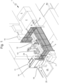
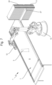
- a ply sorting device 1 according to a first embodiment of the invention is discussed.
- the ply sorting device 1 works in tandem with a cutter 2.
- the material for the plies 3 is supplied as a sheet 4 of fiber material.
- the fiber material may be carbon fiber, but may also be or comprise other type of fiber material, e.g. glass fiber or aramid fiber.
- the fiber material may have woven, or non-woven strands of fibers.
- the strands of fibers typically each have a single orientation.
- the fibers in the material are parallel unidirectional, non woven fiber strands.
- the fiber material may be impregnated with a resin.
- the resin material may be thermosetting or thermoplastic material, and in the finished product forms a matrix material.
- the resin may typically be uncured, e.g. in case of a thermosetting material.
- the resin may be sticky, e.g. in case of uncured resin.
- the plies 3 in this example are unfinished products: they are to be placed in layers, and subjected to heat and pressure to form a product. Because they are unfinished, the plies 3 cut from the sheet 4 of resin impregnated material are delicate, and should be handled with care to prevent loss of integrity, and to prevent contamination.
- the impregnated fiber material may be provided with a protective layer, e.g. a top or bottom backing that is to be removed when the plies 3 are put in the mold. Sharp folding and exertion of (planar) force on the plies 3 is to be prevented. In order to ensure this, the plies 3 are preferably picked, moved and stored in a planar orientation. Due to limited shelf life of the resin as unfinished product, after cutting the plies 3 should be processed to products fairly quickly. Also, prolonged storage of plies 3 or sets of plies 3 is better avoided.
- the sheet of material is typically provided on a roll, which is stored in a protective packaging. After removal of the packaging, the sheet 4 is unrolled from the roll at a roll supply 5, and is placed on a flat conveyor belt 6 of a cutter 2.
- the cutter 2 typically is a numerically controlled X-Y knife, laser or jet cutting machine.
- the cutter 2 cuts plies 3 of different geometries. Plies 3 of different geometries may together make up a set to be used for molding of a composite product.
- a set may typically comprise plies 3 of different size and shape, but may comprise or even consist of plies 3 of the same geometry.
- a composite product may itself be comprised of several sets of plies 3.
- a cutting file is produced by nesting of the plies 3 of several sets. These sets may each be identical, but may also differ. For example, different sets corresponding to smaller and larger products may be nested on the sheet 4 to optimize use of the sheet material.
- the output of the cutter 2 is thus a sheet 4 with cutouts for plies 3, which is transported from the cutter 2 on a flat conveyor belt 6 to a pickup plane 7. In the example of Fig. 1 this is done by an unloading conveyor 8 connected to a sorting conveyor 9 at the same level. In this case, the unloading conveyor 8 defines a flat pickup plane 7 in which the cut sheet 4 lies.
- the plies 3 may be picked as cutouts from the moving sheet on the sorting conveyor 9.
- the plies 3 are typically not in an the order so that subsequent plies 3 can be picked from the sheet 4 to form a set. For example, a ply 3 for a first set may come first, followed by another ply 3 for a second set.
- a ply sorting device 1 comprises a picker 10 and a buffer 11.
- the picker 10 is arranged to pick planar plies 3 of cut resin impregnated fiber material and move them to the buffer 11 in substantially planar orientation.
- the picker 10 is in the example of Fig. 1 embodied as a robotic arm, carrying a gripper head 12. Instead of a robotic arm, another type of moving device for the gripper head 12 may be provided, e.g. a simple rail with a movable carriage for the gripper head. Referring to Fig.
- the gripper head 12 of the picker 10 may comprise a plurality of gripper organs 13 arranged in a gripper plane 14 of the gripper head 12, e.g. suction cups.
- a select group of gripper organs 13 from the plurality of gripper organs 13 arranged in the gripper plane 14 on the picker 10 is actuated by a controller 15 depending on the geometry of the ply 3 to be picked.
- a detection plane may be arranged parallel to the pickup plane 7, e.g. a light screen, to detect any material extending between the pickup plane 7 and the gripper plane 14.
- the buffer 11 comprises a plurality of substantially planar supports 16 each arranged to receive plies 3 from the picker 10 and to support the plies 3 in planar orientation in a stack.
- the controller 15 Based on the data in the cutting file, the controller 15 arranges that the planar plies 3 of cut fiber material of differing geometries are subsequently picked by the picker 10 and are each moved in substantially planar orientation to a selected one of a plurality of supports 16 of the buffer 11.
- the controller 15 is in communication with the cutter 2 and the sorting conveyor 9.
- the controller 15 can use the data of the cutting file to locate the various plies 3, and to select the support where a set is collected to which the ply 3 is to be added.
- the plies 3 are received in a planar orientation to become part of a stacked set of plies 3.
- the completion of sets in the supports 16 of the buffer 11 is used as a boundary condition in the nesting of the plies 3 in the sheet 4.
- the planar supports 16 are movably arranged relative to each other to receive the plies 3.
- the supports 16 can be moved from a storage position in which they have a covering arrangement that prevents receiving of plies 3, to a receiving position that allows receiving of plies 3.
- Such a covering arrangement saves space, and prevents contamination due to sheltering.
- the supports 16 are arranged to be movable perpendicular to their plane.
- the shelves 17 are embodied as trays, so that the plies 3 of the set may be supported in a protected trough.
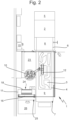
- the shelves 17 are placed in a column, and are liftably mounted to a frame 18 transversely to the longitudinal direction of the shelves 17.
- the shelves 17 are liftably mounted with a variable interspace S to accommodate the picker 10 between shelves 17.
- a lock 19 and a lifting table 20 may cooperate to provide a spacing between the shelves 17.
- the bottom shelve 21 in the spacing shown is in the receiving position, the other shelves 22 are covered and are in the storage position.
- the shelves of the column are thus arranged to be moved relatively to each other in groups. Adjacent shelves of the column can be parted, and provided with interspace to accommodate the gripper head of the picker between the shelves. By moving the shelves of the column up and down, the shelves that are to be parted can be positioned at a fixed height before parting. All shelves can then be made available for the picker to access at a single height position.
- the column may be moved up or down to position the shelves to be parted using the lifting table 20, e.g. by driving it with a spindle via a single motor.
- an upper shelve of a set of shelves to be parted may be held by actuating a locking pin of the lock 19.
- an upper part of the column remains in place, while a lower part of the column moves downward, and the lower shelve 21 of the set of shelves that is on top of the lower part of the column is made accessible for the gripper head 12.
- the lower shelve 21 of a set of shelves to be parted may be moved from a storage position in which it forms a support that is a covering arrangement with a support formed by the upper shelve of the set that prevents receiving of plies, to a receiving position that allows receiving of plies.
- one side 24 of the column of shelves 17 of the buffer 11 facing the picker 10 is part of a stay out zone 23 that during operation is not accessible to humans.
- An opposite side 25 of the column facing away from the picker 10 is part of a safe zone 26 that during operation is accessible to humans.
- the buffer 11 may be implemented in a flexible production cell easily accessible to a robot, and yet be easily and safely accessible to humans as well.
- an operator may remove a set of plies 3 that is completed manually when the shelf is in the receiving position.
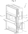
- the supports 16 of the buffer 11 are embodied as shelves 17 that are each slidably mounted to a frame 18 transversely to a longitudinal direction of the shelves 17.
- the shelves 17 are arranged in a column, and are vertically closely interspaced at fixed intervals.
- the shelves 17 are arranged to slide outwards at opposing sides of the column from a covering arrangement that prevents receiving of plies 3, to a receiving position that allows receiving of plies 3.
- the shelf overlaps with other shelves 22, and in de receiving arrangement the shelf is substantially non-overlapping with the other shelves 22 and is free to receive plies 3.
- the receiving position allows the picker 10 to drop plies 3 on the shelf 27; at a side 25 of the column facing away from the picker 10 the receiving position allows an operator to take out the set of plies 3 when completed.
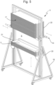
- the supports 16 are embodied as panels of different height, that are slidable on tracks along the sorting conveyor 9. Each panel supports a number of stacks of plies 3. When the stacks are completed to a set, the sets may be removed manually.
- a ply sorting device comprising a picker and a buffer, wherein the picker is arranged to pick planar plies of cut fiber material, in particular resin impregnated material, and move them to the buffer, and wherein the buffer comprises a plurality of substantially planar supports each arranged to receive plies from the picker and to support the plies in planar orientation, preferably in a stack, wherein the planar supports are movably arranged relative to each other to receive the plies.
- a method of sorting plies of differing geometry is disclosed, in particular into sets, according to claim 16, inter alia wherein planar plies of cut fiber material are picked and moved to supports of a buffer where plies are received in a planar orientation, in particular to become part of a stacked set of plies, wherein supports are moved relative to each other to receive the plies.
- the buffer may be part of a cabinet with a controlled environment, e.g. a freezer or light blocking cabinet to improve shelf life of pre-impregnated plies (prepregs) comprising thermosetting or thermoplastic matrix material.
- pre-impregnated plies prepregs
- thermosetting or thermoplastic matrix material thermosetting or thermoplastic matrix material
- plies of cut fiber material may be manually picked and moved to supports of a buffer , e.g. by an operator. This may be done in addition or as an alternative to the picker.
- the cut fiber materials may then be placed manually into trays and/or onto shelves, for example into removable trays and/or onto shelves which have been removed from the buffer. For instance, an operator may remove a tray or shelf from the buffer and place cut plies into the tray or onto the shelf, and subsequently load a stack of plies into the buffer with the tray or shelf. This way, cut plies may be manually picked and collected manually into stacks on the trays and/or shelves, e.g.
- a picker may then access the buffer of the ply sorting device to compose stacks that correspond to sets, and may put plies in the set in the correct order for laying-up.
- a picker may be arranged to operate between buffers. This way a first buffer e.g. may be loaded manually by an operator and trays or plies may be picked from the first buffer by the picker to moved to supports in a second buffer. This can be useful to compose sets of plies, or to put sets of plies in the right order for laying up.
Landscapes
- Engineering & Computer Science (AREA)
- Mechanical Engineering (AREA)
- Warehouses Or Storage Devices (AREA)
- Sorting Of Articles (AREA)
- Specific Conveyance Elements (AREA)
- Preliminary Treatment Of Fibers (AREA)
Claims (24)
- Lagensortiervorrichtung (1) zum Sortieren von Lagen unterschiedlicher Geometrie, umfassend einen Aufnehmer (10) und einen Puffer, wobei der Aufnehmer (10) angeordnet ist, um ebene Lagen (3) aus geschnittenem Fasermaterial aufzunehmen und sie zu dem Puffer (11) zu bewegen, und wobei der Puffer (11) eine Vielzahl von im Wesentlichen ebenen Stützen (16) umfasst, die jeweils angeordnet sind, um Lagen (3) von dem Aufnehmer (10) zu empfangen und die Lagen (3) in einer ebenen Ausrichtung zu stützen, wobei die ebenen Stützen (16) relativ zueinander beweglich angeordnet sind, um die Lagen (3) zu empfangen, dadurch gekennzeichnet, dass die Stützen (16) angeordnet sind, um aus einer Aufbewahrungsposition, in der sie eine Abdeckanordnung aufweisen, die ein Empfangen von Lagen (3) verhindert, in eine Empfangsposition, die ein Empfangen von Lagen (3) ermöglicht, bewegt zu werden.
- Lagensortiervorrichtung (1) nach Anspruch 1, wobei die Stützen (16) senkrecht zu ihrer Ebene voneinander beabstandet sind.
- Lagensortiervorrichtung (1) nach Anspruch 1 oder 2, wobei die Stützen (16) angeordnet sind, um sich entlang ihrer Ebene zu bewegen.
- Lagensortiervorrichtung (1) nach einem der vorhergehenden Ansprüche, wobei die Stützen (16) angeordnet sind, um sich senkrecht zu ihrer Ebene zu bewegen.
- Lagensortiervorrichtung (1) nach einem der vorhergehenden Ansprüche, wobei die Stützen (16) Ablageplatten (17) sind.
- Lagensortiervorrichtung (1) nach Anspruch 5, wobei die Ablageplatten (17) in einem Ständer übereinander angeordnet sind.
- Lagensortiervorrichtung (1) nach Anspruch 5 oder 6, wobei die Ablageplatten (17) jeweils quer zu einer Längsrichtung der Ablageplatten (17) gleitbar an einem Rahmen montiert sind.
- Lagensortiervorrichtung (1) nach Anspruch 6 oder 7, wobei die Ablageplatten (17) angeordnet sind, um von dem Ständer nach zu außen zu gleiten, vorzugsweise an gegenüberliegenden Seiten des Ständers.
- Lagensortiervorrichtung (1) nach Anspruch 8, wobei eine Seite des Ständers, die dem Aufnehmer (10) zugewandt ist, Teil einer Sperrzone (23) ist, die während des Betriebs für Menschen nicht zugänglich ist, und wobei eine gegenüberliegende Seite des Ständers, die von dem Aufnehmer (10) abgewandt ist, Teil einer sicheren Zone ist, die während des Betrieb für Menschen zugänglich ist.
- Lagensortiervorrichtung (1) nach Anspruch 5 oder 6, wobei die Ablageplatten (17) quer zu einer Längsrichtung der Ablageplatten (17) anhebbar an einem Rahmen (18) montiert sind.
- Lagensortiervorrichtung (1) nach Anspruch 10, wobei die Ablageplatten (17) mit einem variablem Zwischenraum anhebbar montiert sind, um den Aufnehmer (10) zwischen den Ablageplatten (17) unterzubringen.
- Lagensortiervorrichtung (1) nach einem der vorhergehenden Ansprüche, ferner umfassend eine im Wesentlichen ebene Aufnahmeebene (7), vorzugsweise eine Förderbandoberfläche, die der Ausgabe eines Bahnschneiders (2) zugeordnet ist.
- Lagensortiervorrichtung (1) nach einem der vorhergehenden Ansprüche, wobei der Aufnehmer (10) eine Vielzahl von Greiferorganen (13), die in einer Greiferebene (14) angeordnete sind, und/oder ein Sichtsystem zur Beurteilung der Lagen (3) umfasst.
- Lagensortiervorrichtung (1) nach Anspruch 12 und 13, ferner umfassend eine Erfassungsebene, die parallel zu der Aufnahmeebene (7) angeordnet ist, um Material zu erfassen, das sich zwischen der Aufnahmeebene (7) und der Greiferebene erstreckt.
- Lagensortiervorrichtung (1) nach einem der vorangehenden Ansprüche, die einem Bahnschneider (3) betriebsmäßig zugeordnet ist, der angeordnet ist, um Lagen (3) aus einer Bahn (4) zu schneiden.
- Verfahren zum Sortieren von Lagen (3) unterschiedlicher Geometrie, insbesondere unter Verwendung einer Lagensortiervorrichtung (1) nach einem der vorhergehenden Ansprüche, wobei ebene Lagen (3) aus geschnittenem Fasermaterial aufgenommen und zu Stützen (16) eines Puffers (11) bewegt werden, wo Lagen (3) in einer ebenen Ausrichtung empfangen werden, wobei die Stützen (16) relativ zueinander bewegt werden, um die Lagen (3) zu empfangen, dadurch gekennzeichnet, dass die Stützen (16) aus einer Aufbewahrungsposition, in der sie eine Abdeckanordnung aufweisen, die ein Empfangen von Lagen (3) verhindert, in eine Empfangsposition, die ein Empfangen von Lagen (3) ermöglicht, bewegt werden.
- Verfahren nach Anspruch 16, wobei die Stützen (16) entlang ihrer Ebene bewegt werden.
- Verfahren nach Anspruch 16 oder 17, wobei die Stützen (16) senkrecht zu ihrer Ebene bewegt werden.
- Verfahren nach Anspruch 18, wobei die Stützen (16) in einem Hebevorgang auseinander bewegt werden, um Lagen (3) zu empfangen.
- Verfahren nach einem der Ansprüche 16-19, wobei die Lagen (3) als Ausschnitte aus einer Bahn (4), insbesondere einer sich bewegenden Bahn (4), aufgenommen werden.
- Verfahren nach Anspruch 20, wobei die ausgeschnittenen Lagen (3) in der Bahn verschachtelt werden, um die Nutzung von Bahnmaterial zu optimieren.
- Verfahren nach Anspruch 21, wobei die Vervollständigung von Sätzen in den Stützen (16) des Puffers (11) als Begrenzungsbedingung bei der Verschachtelung der Lagen (3) in der Bahn verwendet wird.
- Verfahren nach einem der Ansprüche 16-22, wobei als Teil des Schritts des Aufnehmens einer Lage (3) eine ausgewählte Gruppe von Greiferorganen (13) aus einer Vielzahl von Greiferorganen (13), die in einer Greiferebene an einem Aufnehmer (10) angeordnet ist, abhängig von der Geometrie der aufzunehmenden Lage (3) betätigt wird.
- Verfahren nach einem der Ansprüche 16-23, wobei als Teil des Schritts des Aufnehmens einer Lage (3) das Auftreten eines Nachlaufens von Material von einem Aufnehmer (10) erfasst wird.
Priority Applications (1)
| Application Number | Priority Date | Filing Date | Title |
|---|---|---|---|
| EP23162146.7A EP4215465A1 (de) | 2017-06-19 | 2018-06-19 | Vorrichtung und verfahren zum sortieren von lagen |
Applications Claiming Priority (2)
| Application Number | Priority Date | Filing Date | Title |
|---|---|---|---|
| NL2019094A NL2019094B1 (en) | 2017-06-19 | 2017-06-19 | Device and method for sorting plies |
| PCT/NL2018/050397 WO2018236212A1 (en) | 2017-06-19 | 2018-06-19 | DEVICE AND METHOD FOR SORTING LAYERS |
Related Child Applications (2)
| Application Number | Title | Priority Date | Filing Date |
|---|---|---|---|
| EP23162146.7A Division EP4215465A1 (de) | 2017-06-19 | 2018-06-19 | Vorrichtung und verfahren zum sortieren von lagen |
| EP23162146.7A Division-Into EP4215465A1 (de) | 2017-06-19 | 2018-06-19 | Vorrichtung und verfahren zum sortieren von lagen |
Publications (3)
| Publication Number | Publication Date |
|---|---|
| EP3642143A1 EP3642143A1 (de) | 2020-04-29 |
| EP3642143B1 true EP3642143B1 (de) | 2023-06-07 |
| EP3642143C0 EP3642143C0 (de) | 2023-06-07 |
Family
ID=60183045
Family Applications (2)
| Application Number | Title | Priority Date | Filing Date |
|---|---|---|---|
| EP18740329.0A Active EP3642143B1 (de) | 2017-06-19 | 2018-06-19 | Vorrichtung und verfahren zum sortieren von lagen |
| EP23162146.7A Pending EP4215465A1 (de) | 2017-06-19 | 2018-06-19 | Vorrichtung und verfahren zum sortieren von lagen |
Family Applications After (1)
| Application Number | Title | Priority Date | Filing Date |
|---|---|---|---|
| EP23162146.7A Pending EP4215465A1 (de) | 2017-06-19 | 2018-06-19 | Vorrichtung und verfahren zum sortieren von lagen |
Country Status (7)
| Country | Link |
|---|---|
| US (2) | US11883855B2 (de) |
| EP (2) | EP3642143B1 (de) |
| JP (2) | JP2020524078A (de) |
| CN (1) | CN111065591A (de) |
| CA (1) | CA3067774C (de) |
| NL (1) | NL2019094B1 (de) |
| WO (1) | WO2018236212A1 (de) |
Families Citing this family (7)
| Publication number | Priority date | Publication date | Assignee | Title |
|---|---|---|---|---|
| NL2019094B1 (en) | 2017-06-19 | 2018-12-27 | Airborne Int B V | Device and method for sorting plies |
| NL2023372B1 (en) | 2019-06-25 | 2021-02-01 | Airborne Int B V | Preforming system and method |
| AT523964B1 (de) * | 2020-07-08 | 2023-05-15 | Gfm Gmbh | Verfahren zum Bereitstellen von Zuschnitten aus einer Faserbahn |
| CN111908080B (zh) * | 2020-07-27 | 2022-01-25 | 机械科学研究总院海西(福建)分院有限公司 | 一种胶带式铺席工装结构及操作方法 |
| CN113334415B (zh) * | 2021-07-13 | 2024-08-06 | 斯图尔茨机器(济南)有限公司 | 机器人自动分拣系统和方法和抓手 |
| US12172193B2 (en) * | 2022-02-16 | 2024-12-24 | Mekanika Inc. | System and method for quality control of wood pieces to be packaged |
| CN117283352A (zh) * | 2022-06-16 | 2023-12-26 | 上海中车瑞伯德智能系统股份有限公司 | 一种用于大幅面板料切割的自动上下料及分拣生产装置 |
Family Cites Families (35)
| Publication number | Priority date | Publication date | Assignee | Title |
|---|---|---|---|---|
| JPS6044407B2 (ja) | 1979-10-31 | 1985-10-03 | 金井 宏之 | 梳綿機の予備開繊ロ−ラの取付け装置 |
| JPS6044407A (ja) * | 1983-08-19 | 1985-03-09 | Shinku Lab:Kk | 多段パレット装置 |
| JPS6118636A (ja) * | 1984-07-05 | 1986-01-27 | Toppan Printing Co Ltd | カ−トン束のパレツト積載装置 |
| JPS6118636U (ja) | 1984-07-06 | 1986-02-03 | アルプス電気株式会社 | 波形整形回路装置 |
| JPH03232604A (ja) | 1990-02-08 | 1991-10-16 | Mitsubishi Heavy Ind Ltd | 磁気カートリッジテープ収納箱 |
| JPH06270084A (ja) | 1993-03-22 | 1994-09-27 | Amada Metrecs Co Ltd | ワーク選別用ロボットおよびそのロボットを備えた加工装置 |
| JPH0881017A (ja) | 1994-09-14 | 1996-03-26 | Brother Ind Ltd | ストッカー |
| JPH08333023A (ja) * | 1995-06-09 | 1996-12-17 | Daido Kikai Seisakusho:Kk | 物品自動移載装置 |
| JP4035901B2 (ja) * | 1998-10-09 | 2008-01-23 | 村田機械株式会社 | 板材搬送装置 |
| FR2795014B1 (fr) * | 1999-06-21 | 2001-10-19 | Lectra Systemes Sa | Procede et installation pour la decoupe et le dechargement automatique de piles de pieces dans un matelas de matiere en feuille |
| JP4348520B2 (ja) * | 2003-09-16 | 2009-10-21 | 村田機械株式会社 | 搬送システム |
| US20060099064A1 (en) * | 2004-11-08 | 2006-05-11 | Yaron Anaki | On-the-fly robotic stacking system for flat glass |
| DE202005013047U1 (de) | 2005-08-18 | 2005-11-03 | Korte, Hermann, Dipl.-Ing. | Lagerungsvorrichtung |
| CN2860212Y (zh) | 2005-11-21 | 2007-01-24 | 邓耀承 | 自由式升降搁物板 |
| TWI269772B (en) * | 2006-01-24 | 2007-01-01 | Au Optronics Corp | Apparatus for loading and unloading workpiece |
| ATE537126T1 (de) * | 2006-08-17 | 2011-12-15 | Albat & Wirsam Software Ag | Verfahren und vorrichtung zum zuschneiden von rohglasplatten |
| JP4823004B2 (ja) | 2006-09-28 | 2011-11-24 | 株式会社クボタ | トラックフレーム |
| DE202006016309U1 (de) * | 2006-10-23 | 2006-12-21 | Keuro Besitz Gmbh & Co Edv-Dienstleistungs Kg | Regallager |
| JP5163860B2 (ja) * | 2007-07-30 | 2013-03-13 | 株式会社Ihi | 基板搬送装置 |
| DE102008006956B3 (de) * | 2008-01-31 | 2009-09-03 | Grenzebach Maschinenbau Gmbh | Portalumsetzer für großflächige Glasplatten |
| DE102008045369B4 (de) * | 2008-09-02 | 2013-11-21 | Grenzebach Maschinenbau Gmbh | Vorrichtung und Verfahren zum Aufnehmen von Glasplatten |
| CN201624339U (zh) * | 2010-03-23 | 2010-11-10 | 朱建华 | 大型兽类标本存放架 |
| DE102011117640B4 (de) * | 2011-11-04 | 2014-04-24 | Audi Ag | Vorrichtung zur teilmanuellen Stapelung und Verladung von Blechformteilen an Pressen und Pressenstraßen, sowie Tischeinrichtung zur Verwendung in dieser Vorrichtung |
| CN102756921B (zh) | 2012-07-10 | 2014-12-03 | 中国科学院宁波材料技术与工程研究所 | 纤维片材的工业机器人自动层叠系统 |
| JP6118636B2 (ja) | 2013-05-20 | 2017-04-19 | 西川ゴム工業株式会社 | センサー付きプロテクター |
| CN204063766U (zh) * | 2014-07-01 | 2014-12-31 | 天津市豪威特达科技发展有限公司 | 一种冷库用可调货架 |
| CN104799588B (zh) * | 2015-05-19 | 2018-01-12 | 国家电网公司 | 可升降隔板层储藏柜 |
| CN106276007A (zh) * | 2015-06-23 | 2017-01-04 | 辽宁聚龙海目星智能物流科技有限公司 | 一种升降式格子容积可变的智能物流柜 |
| CN105290785B (zh) | 2015-12-01 | 2017-10-27 | 长沙长泰机器人有限公司 | 基于视觉的工件分拣及组装系统 |
| AU2017285474B2 (en) * | 2016-06-14 | 2022-07-28 | Justoy Pty Ltd | Plate storage assembly |
| CN206213590U (zh) | 2016-08-23 | 2017-06-06 | 北京京东尚科信息技术有限公司 | 货架 |
| CN107010417B (zh) * | 2017-03-20 | 2020-03-06 | 京东方科技集团股份有限公司 | 用于显示屏基板的存放装置及取放显示屏基板的控制方法 |
| AT519992B1 (de) * | 2017-05-19 | 2019-07-15 | Stefan Barbaric | Vorrichtung zur Zwischenlagerung plattenförmiger Werkstücke |
| NL2019094B1 (en) | 2017-06-19 | 2018-12-27 | Airborne Int B V | Device and method for sorting plies |
| US10720353B2 (en) * | 2018-07-04 | 2020-07-21 | Murata Machinery, Ltd. | Opener apparatus |
-
2017
- 2017-06-19 NL NL2019094A patent/NL2019094B1/nl not_active IP Right Cessation
-
2018
- 2018-06-19 CN CN201880046546.7A patent/CN111065591A/zh active Pending
- 2018-06-19 EP EP18740329.0A patent/EP3642143B1/de active Active
- 2018-06-19 US US16/623,734 patent/US11883855B2/en active Active
- 2018-06-19 WO PCT/NL2018/050397 patent/WO2018236212A1/en not_active Ceased
- 2018-06-19 EP EP23162146.7A patent/EP4215465A1/de active Pending
- 2018-06-19 CA CA3067774A patent/CA3067774C/en active Active
- 2018-06-19 JP JP2019571474A patent/JP2020524078A/ja active Pending
-
2023
- 2023-02-08 JP JP2023017787A patent/JP7581397B2/ja active Active
- 2023-12-28 US US18/399,441 patent/US12569886B2/en active Active
Also Published As
| Publication number | Publication date |
|---|---|
| EP4215465A1 (de) | 2023-07-26 |
| US11883855B2 (en) | 2024-01-30 |
| JP2023054042A (ja) | 2023-04-13 |
| CA3067774A1 (en) | 2018-12-27 |
| US20200215579A1 (en) | 2020-07-09 |
| NL2019094B1 (en) | 2018-12-27 |
| WO2018236212A1 (en) | 2018-12-27 |
| US12569886B2 (en) | 2026-03-10 |
| JP7581397B2 (ja) | 2024-11-12 |
| EP3642143C0 (de) | 2023-06-07 |
| CA3067774C (en) | 2022-10-18 |
| WO2018236212A8 (en) | 2020-01-09 |
| US20240123470A1 (en) | 2024-04-18 |
| CN111065591A (zh) | 2020-04-24 |
| JP2020524078A (ja) | 2020-08-13 |
| EP3642143A1 (de) | 2020-04-29 |
Similar Documents
| Publication | Publication Date | Title |
|---|---|---|
| US12569886B2 (en) | Device and method for sorting plies | |
| US12162686B2 (en) | Automated decant system | |
| EP3990243B1 (de) | Vorformungssystem und -verfahren | |
| US9963294B2 (en) | Arrangement and method in a warehouse | |
| EP3697601B1 (de) | Herstellung eines verbundstoffes | |
| NL2037174B1 (en) | Method of providing a cut-out product from a sheet | |
| NL2037150B1 (en) | Method and system for assembling a product kit for manufacturing a laminated product | |
| KR102947542B1 (ko) | 플라이 정위치 픽킹을 위한 버퍼 장치, 플라이 보관을 위한 적재 장치 및 프리폼 제조 워크셀 설비 | |
| EP3746297B1 (de) | Herstellung von schichtprodukten | |
| KR20240176153A (ko) | 플라이 정위치 픽킹을 위한 버퍼 장치, 플라이 보관을 위한 적재 장치 및 프리폼 제조 워크셀 설비 | |
| JP5009589B2 (ja) | セパレータおよびこれを備えた板材加工システム | |
| CN103754684A (zh) | 一种小张产品出货的方法及其装置 |
Legal Events
| Date | Code | Title | Description |
|---|---|---|---|
| STAA | Information on the status of an ep patent application or granted ep patent |
Free format text: STATUS: UNKNOWN |
|
| STAA | Information on the status of an ep patent application or granted ep patent |
Free format text: STATUS: THE INTERNATIONAL PUBLICATION HAS BEEN MADE |
|
| PUAI | Public reference made under article 153(3) epc to a published international application that has entered the european phase |
Free format text: ORIGINAL CODE: 0009012 |
|
| STAA | Information on the status of an ep patent application or granted ep patent |
Free format text: STATUS: REQUEST FOR EXAMINATION WAS MADE |
|
| 17P | Request for examination filed |
Effective date: 20191230 |
|
| AK | Designated contracting states |
Kind code of ref document: A1 Designated state(s): AL AT BE BG CH CY CZ DE DK EE ES FI FR GB GR HR HU IE IS IT LI LT LU LV MC MK MT NL NO PL PT RO RS SE SI SK SM TR |
|
| AX | Request for extension of the european patent |
Extension state: BA ME |
|
| DAV | Request for validation of the european patent (deleted) | ||
| DAX | Request for extension of the european patent (deleted) | ||
| RIN1 | Information on inventor provided before grant (corrected) |
Inventor name: VAN SIGHEM, JOHANNES PAUL Inventor name: HOFSTEDE, CASPER MARINUS Inventor name: VAN OVERBEEK, THOMAS THEODORUS ARNOLDUS Inventor name: STELMA, TJALLING |
|
| RAP1 | Party data changed (applicant data changed or rights of an application transferred) |
Owner name: AIRBORNE INTERNATIONAL B.V. |
|
| STAA | Information on the status of an ep patent application or granted ep patent |
Free format text: STATUS: EXAMINATION IS IN PROGRESS |
|
| 17Q | First examination report despatched |
Effective date: 20210910 |
|
| REG | Reference to a national code |
Ref country code: DE Ref legal event code: R079 Free format text: PREVIOUS MAIN CLASS: B65G0057030000 Ipc: B65G0047510000 Ref country code: DE Ref legal event code: R079 Ref document number: 602018051060 Country of ref document: DE Free format text: PREVIOUS MAIN CLASS: B65G0057030000 Ipc: B65G0047510000 |
|
| GRAP | Despatch of communication of intention to grant a patent |
Free format text: ORIGINAL CODE: EPIDOSNIGR1 |
|
| STAA | Information on the status of an ep patent application or granted ep patent |
Free format text: STATUS: GRANT OF PATENT IS INTENDED |
|
| RIC1 | Information provided on ipc code assigned before grant |
Ipc: B07C 5/36 20060101ALI20221028BHEP Ipc: B65G 47/51 20060101AFI20221028BHEP |
|
| INTG | Intention to grant announced |
Effective date: 20221116 |
|
| GRAS | Grant fee paid |
Free format text: ORIGINAL CODE: EPIDOSNIGR3 |
|
| GRAA | (expected) grant |
Free format text: ORIGINAL CODE: 0009210 |
|
| STAA | Information on the status of an ep patent application or granted ep patent |
Free format text: STATUS: THE PATENT HAS BEEN GRANTED |
|
| AK | Designated contracting states |
Kind code of ref document: B1 Designated state(s): AL AT BE BG CH CY CZ DE DK EE ES FI FR GB GR HR HU IE IS IT LI LT LU LV MC MK MT NL NO PL PT RO RS SE SI SK SM TR |
|
| REG | Reference to a national code |
Ref country code: GB Ref legal event code: FG4D |
|
| REG | Reference to a national code |
Ref country code: CH Ref legal event code: EP Ref country code: AT Ref legal event code: REF Ref document number: 1574452 Country of ref document: AT Kind code of ref document: T Effective date: 20230615 |
|
| REG | Reference to a national code |
Ref country code: DE Ref legal event code: R096 Ref document number: 602018051060 Country of ref document: DE |
|
| U01 | Request for unitary effect filed |
Effective date: 20230705 |
|
| U07 | Unitary effect registered |
Designated state(s): AT BE BG DE DK EE FI FR IT LT LU LV MT NL PT SE SI Effective date: 20230719 |
|
| U20 | Renewal fee for the european patent with unitary effect paid |
Year of fee payment: 6 Effective date: 20230727 |
|
| REG | Reference to a national code |
Ref country code: LT Ref legal event code: MG9D |
|
| PG25 | Lapsed in a contracting state [announced via postgrant information from national office to epo] |
Ref country code: NO Free format text: LAPSE BECAUSE OF FAILURE TO SUBMIT A TRANSLATION OF THE DESCRIPTION OR TO PAY THE FEE WITHIN THE PRESCRIBED TIME-LIMIT Effective date: 20230907 Ref country code: ES Free format text: LAPSE BECAUSE OF FAILURE TO SUBMIT A TRANSLATION OF THE DESCRIPTION OR TO PAY THE FEE WITHIN THE PRESCRIBED TIME-LIMIT Effective date: 20230607 |
|
| PG25 | Lapsed in a contracting state [announced via postgrant information from national office to epo] |
Ref country code: RS Free format text: LAPSE BECAUSE OF FAILURE TO SUBMIT A TRANSLATION OF THE DESCRIPTION OR TO PAY THE FEE WITHIN THE PRESCRIBED TIME-LIMIT Effective date: 20230607 Ref country code: HR Free format text: LAPSE BECAUSE OF FAILURE TO SUBMIT A TRANSLATION OF THE DESCRIPTION OR TO PAY THE FEE WITHIN THE PRESCRIBED TIME-LIMIT Effective date: 20230607 Ref country code: GR Free format text: LAPSE BECAUSE OF FAILURE TO SUBMIT A TRANSLATION OF THE DESCRIPTION OR TO PAY THE FEE WITHIN THE PRESCRIBED TIME-LIMIT Effective date: 20230908 |
|
| PG25 | Lapsed in a contracting state [announced via postgrant information from national office to epo] |
Ref country code: SK Free format text: LAPSE BECAUSE OF FAILURE TO SUBMIT A TRANSLATION OF THE DESCRIPTION OR TO PAY THE FEE WITHIN THE PRESCRIBED TIME-LIMIT Effective date: 20230607 |
|
| PG25 | Lapsed in a contracting state [announced via postgrant information from national office to epo] |
Ref country code: IS Free format text: LAPSE BECAUSE OF FAILURE TO SUBMIT A TRANSLATION OF THE DESCRIPTION OR TO PAY THE FEE WITHIN THE PRESCRIBED TIME-LIMIT Effective date: 20231007 |
|
| PG25 | Lapsed in a contracting state [announced via postgrant information from national office to epo] |
Ref country code: SM Free format text: LAPSE BECAUSE OF FAILURE TO SUBMIT A TRANSLATION OF THE DESCRIPTION OR TO PAY THE FEE WITHIN THE PRESCRIBED TIME-LIMIT Effective date: 20230607 Ref country code: SK Free format text: LAPSE BECAUSE OF FAILURE TO SUBMIT A TRANSLATION OF THE DESCRIPTION OR TO PAY THE FEE WITHIN THE PRESCRIBED TIME-LIMIT Effective date: 20230607 Ref country code: RO Free format text: LAPSE BECAUSE OF FAILURE TO SUBMIT A TRANSLATION OF THE DESCRIPTION OR TO PAY THE FEE WITHIN THE PRESCRIBED TIME-LIMIT Effective date: 20230607 Ref country code: IS Free format text: LAPSE BECAUSE OF FAILURE TO SUBMIT A TRANSLATION OF THE DESCRIPTION OR TO PAY THE FEE WITHIN THE PRESCRIBED TIME-LIMIT Effective date: 20231007 Ref country code: CZ Free format text: LAPSE BECAUSE OF FAILURE TO SUBMIT A TRANSLATION OF THE DESCRIPTION OR TO PAY THE FEE WITHIN THE PRESCRIBED TIME-LIMIT Effective date: 20230607 |
|
| REG | Reference to a national code |
Ref country code: CH Ref legal event code: PL |
|
| PG25 | Lapsed in a contracting state [announced via postgrant information from national office to epo] |
Ref country code: PL Free format text: LAPSE BECAUSE OF FAILURE TO SUBMIT A TRANSLATION OF THE DESCRIPTION OR TO PAY THE FEE WITHIN THE PRESCRIBED TIME-LIMIT Effective date: 20230607 |
|
| REG | Reference to a national code |
Ref country code: DE Ref legal event code: R097 Ref document number: 602018051060 Country of ref document: DE |
|
| PG25 | Lapsed in a contracting state [announced via postgrant information from national office to epo] |
Ref country code: MC Free format text: LAPSE BECAUSE OF FAILURE TO SUBMIT A TRANSLATION OF THE DESCRIPTION OR TO PAY THE FEE WITHIN THE PRESCRIBED TIME-LIMIT Effective date: 20230607 |
|
| REG | Reference to a national code |
Ref country code: IE Ref legal event code: MM4A |
|
| PG25 | Lapsed in a contracting state [announced via postgrant information from national office to epo] |
Ref country code: MC Free format text: LAPSE BECAUSE OF FAILURE TO SUBMIT A TRANSLATION OF THE DESCRIPTION OR TO PAY THE FEE WITHIN THE PRESCRIBED TIME-LIMIT Effective date: 20230607 |
|
| PLBE | No opposition filed within time limit |
Free format text: ORIGINAL CODE: 0009261 |
|
| STAA | Information on the status of an ep patent application or granted ep patent |
Free format text: STATUS: NO OPPOSITION FILED WITHIN TIME LIMIT |
|
| PG25 | Lapsed in a contracting state [announced via postgrant information from national office to epo] |
Ref country code: IE Free format text: LAPSE BECAUSE OF NON-PAYMENT OF DUE FEES Effective date: 20230619 |
|
| PG25 | Lapsed in a contracting state [announced via postgrant information from national office to epo] |
Ref country code: IE Free format text: LAPSE BECAUSE OF NON-PAYMENT OF DUE FEES Effective date: 20230619 Ref country code: CH Free format text: LAPSE BECAUSE OF NON-PAYMENT OF DUE FEES Effective date: 20230630 |
|
| 26N | No opposition filed |
Effective date: 20240308 |
|
| U21 | Renewal fee for the european patent with unitary effect paid with additional fee |
Year of fee payment: 7 Effective date: 20241210 |
|
| PG25 | Lapsed in a contracting state [announced via postgrant information from national office to epo] |
Ref country code: CY Free format text: LAPSE BECAUSE OF FAILURE TO SUBMIT A TRANSLATION OF THE DESCRIPTION OR TO PAY THE FEE WITHIN THE PRESCRIBED TIME-LIMIT; INVALID AB INITIO Effective date: 20180619 |
|
| PG25 | Lapsed in a contracting state [announced via postgrant information from national office to epo] |
Ref country code: HU Free format text: LAPSE BECAUSE OF FAILURE TO SUBMIT A TRANSLATION OF THE DESCRIPTION OR TO PAY THE FEE WITHIN THE PRESCRIBED TIME-LIMIT; INVALID AB INITIO Effective date: 20180619 |
|
| PG25 | Lapsed in a contracting state [announced via postgrant information from national office to epo] |
Ref country code: TR Free format text: LAPSE BECAUSE OF FAILURE TO SUBMIT A TRANSLATION OF THE DESCRIPTION OR TO PAY THE FEE WITHIN THE PRESCRIBED TIME-LIMIT Effective date: 20230607 |
|
| PGFP | Annual fee paid to national office [announced via postgrant information from national office to epo] |
Ref country code: GB Payment date: 20251219 Year of fee payment: 8 |
|
| U21 | Renewal fee for the european patent with unitary effect paid with additional fee |
Year of fee payment: 8 Effective date: 20251229 |