EP3894096B1 - Procédé de fonctionnement d'un système de pression et système de pression - Google Patents
Procédé de fonctionnement d'un système de pression et système de pression Download PDFInfo
- Publication number
- EP3894096B1 EP3894096B1 EP19806250.7A EP19806250A EP3894096B1 EP 3894096 B1 EP3894096 B1 EP 3894096B1 EP 19806250 A EP19806250 A EP 19806250A EP 3894096 B1 EP3894096 B1 EP 3894096B1
- Authority
- EP
- European Patent Office
- Prior art keywords
- transmission device
- signal
- cartridge
- dispensing
- operating mode
- Prior art date
- Legal status (The legal status is an assumption and is not a legal conclusion. Google has not performed a legal analysis and makes no representation as to the accuracy of the status listed.)
- Active
Links
Images


Classifications
-
- B—PERFORMING OPERATIONS; TRANSPORTING
- B05—SPRAYING OR ATOMISING IN GENERAL; APPLYING FLUENT MATERIALS TO SURFACES, IN GENERAL
- B05C—APPARATUS FOR APPLYING FLUENT MATERIALS TO SURFACES, IN GENERAL
- B05C17/00—Hand tools or apparatus using hand held tools, for applying liquids or other fluent materials to, for spreading applied liquids or other fluent materials on, or for partially removing applied liquids or other fluent materials from, surfaces
- B05C17/005—Hand tools or apparatus using hand held tools, for applying liquids or other fluent materials to, for spreading applied liquids or other fluent materials on, or for partially removing applied liquids or other fluent materials from, surfaces for discharging material from a reservoir or container located in or on the hand tool through an outlet orifice by pressure without using surface contacting members like pads or brushes
- B05C17/01—Hand tools or apparatus using hand held tools, for applying liquids or other fluent materials to, for spreading applied liquids or other fluent materials on, or for partially removing applied liquids or other fluent materials from, surfaces for discharging material from a reservoir or container located in or on the hand tool through an outlet orifice by pressure without using surface contacting members like pads or brushes with manually mechanically or electrically actuated piston or the like
- B05C17/0103—Hand tools or apparatus using hand held tools, for applying liquids or other fluent materials to, for spreading applied liquids or other fluent materials on, or for partially removing applied liquids or other fluent materials from, surfaces for discharging material from a reservoir or container located in or on the hand tool through an outlet orifice by pressure without using surface contacting members like pads or brushes with manually mechanically or electrically actuated piston or the like with electrically actuated piston or the like
-
- B—PERFORMING OPERATIONS; TRANSPORTING
- B05—SPRAYING OR ATOMISING IN GENERAL; APPLYING FLUENT MATERIALS TO SURFACES, IN GENERAL
- B05C—APPARATUS FOR APPLYING FLUENT MATERIALS TO SURFACES, IN GENERAL
- B05C17/00—Hand tools or apparatus using hand held tools, for applying liquids or other fluent materials to, for spreading applied liquids or other fluent materials on, or for partially removing applied liquids or other fluent materials from, surfaces
- B05C17/005—Hand tools or apparatus using hand held tools, for applying liquids or other fluent materials to, for spreading applied liquids or other fluent materials on, or for partially removing applied liquids or other fluent materials from, surfaces for discharging material from a reservoir or container located in or on the hand tool through an outlet orifice by pressure without using surface contacting members like pads or brushes
- B05C17/00553—Hand tools or apparatus using hand held tools, for applying liquids or other fluent materials to, for spreading applied liquids or other fluent materials on, or for partially removing applied liquids or other fluent materials from, surfaces for discharging material from a reservoir or container located in or on the hand tool through an outlet orifice by pressure without using surface contacting members like pads or brushes with means allowing the stock of material to consist of at least two different components
Definitions
- the invention relates to a method for operating a squeezing system comprising a squeezing device and a cartridge device according to the preamble of claim 1.
- the invention further relates to a squeezing system for carrying out such a method according to the subject matter of claim 8.
- Squeezing devices are used, for example, in the construction sector for squeezing silicone or other liquid or viscous building materials from cartridge devices. Squeezing devices are also known which are designed to accommodate cartridge devices which have two or more chambers.
- Such cartridge devices can contain, for example, a two-component mortar mass, with a hardenable resin component being arranged in one chamber or cartridge of the cartridge device and a hardener component being arranged in another chamber or cartridge of the cartridge device which is arranged separately from it in a reaction-inhibiting manner.
- Cartridge devices with such two-component mortar masses are used, for example, as injection mortar for the chemical anchoring of metal elements in mineral substrates, such as in particular buildings made of brickwork, concrete or natural stone.
- the drill holes required to attach the anchoring means are made in the mineral substrate, after which the hardenable resin component is mixed with the hardener component of the two-component mortar mass and introduced into the drill hole, after which the anchoring means to be attached is introduced and adjusted, after which the mortar mass hardens.
- the typical design of such an dispensing device provides for dispensing pistons arranged on push rods, which move in the direction of the dispensing opening of the cartridge. The push rods are driven by a feed mechanism.
- Squeezers are made from US2014/0209630 A1 , US2013/0075427 A1 and DE102011075873 A1 previously known.
- the cartridge device used is matched to the dispensing device. Using combinations of cartridge device and dispensing device that are not matched to one another can damage both the cartridge device and the dispensing device. In addition, if the combinations are not matched, it is possible that the hardened compound that is dispensed does not have the desired mechanical properties after hardening.
- the method according to the invention makes it easy to determine whether a compatible dispensing system is present and whether the cartridge device used is suitable for use in the dispensing device. If the combination is compatible, the drive device is switched to normal or regular operation in the second operating mode, while if the combination is not compatible, the drive device is switched to the third operating mode.
- the risk of damage to both the cartridge device and the dispensing device can thereby be reduced or prevented in a simple, reliable and safe manner.
- the effects of user misconduct on the functionality of the cartridge device and/or the dispensing device can be reduced or prevented if, for example, incorrect insertion of the cartridge device into the receiving space is detected.
- the exchange of information between the cartridge device and the dispensing device makes it possible to optimize a dispensing process with regard to the cartridge device used in each case.
- the first operating mode of the drive device is a deactivation mode in which no current is supplied from the power supply to the drive device or a coupling of the drive mechanism is released. In this way, in a basic state of the squeezing system, any undesired actuation of the drive device is reliably prevented by decoupling it from the drive device.
- Damage to the squeezing system can be particularly reliably prevented if the third operating mode of the drive device corresponds to the first operating mode of the drive device and the drive device in the third operating mode is in particular in a deactivation mode in which the drive device is preferably decoupled from the energy supply.
- the drive device remains in the first operating mode in a simple manner by interrupting the energy path between the energy supply and the drive device.
- the dispensing device in the third operating mode of the drive device is subjected to a feed in a first direction at a first speed which is lower than a speed of the feed of the dispensing device in the first direction in the second operating mode of the drive device.
- the signal generator of the cartridge device sends out at least one third signal, which sets the drive device to the first operating mode, i.e. that the drive device remains in the first operating mode or is placed in it if the third signal exceeds a threshold value stored in the control device or is outside a specified range.
- This makes it easy, for example, to prevent the dispensing piston from moving when requested by the user if an expiration date of the cartridge device or a shelf life of a perishable chemical stored in the cartridge device has been exceeded or if a permissible temperature range stored on the cartridge device is not present. In this way, it can be ensured, for example, that material in the cartridge device has the desired mechanical properties in full after application and curing.
- a warning signal is emitted by a warning signal generator in the third operating mode of the drive device. This allows the user to be informed acoustically, visually or haptically, for example, if a cartridge device is present that is not compatible with the dispenser.
- Such a warning signal can also be emitted by a warning signal generator or in addition to this if the third signal exceeds a threshold value stored in the control device.
- a squeezing system for carrying out a method specified in more detail above with a squeezing device and a cartridge device, wherein the squeezing device has at least one receiving space for receiving the cartridge device, at least one squeezing device for exerting a force on the cartridge device, a control device, a drive device and a power supply, and wherein the cartridge device has a signal generator for emitting at least one signal and the squeezing device has at least one sensor for receiving at least one signal from the signal generator.
- the dispensing system designed according to the invention makes it easy to determine whether a cartridge device is suitable for use in the dispensing device.
- the risk of damage to both the cartridge device and the dispensing device can thereby be reduced or prevented in a simple, reliable and safe manner.
- the effects of user misconduct on the functionality of the cartridge device and/or the dispensing device can be reduced or prevented.
- the cartridge device can be designed with one chamber or cartridge or with two or more chambers or cartridges, with a cartridge device having multiple cartridges, in particular different materials being arranged in each cartridge.
- the receiving space of the dispensing device is designed to receive the cartridge of the cartridge device, which is in particular cylindrical in shape.
- the cartridge device has a two- or multi-component mortar mass, with a hardenable resin component being arranged in one cartridge of the cartridge device and a hardener component being arranged in another chamber of the same cartridge device, which is arranged separately from it in a reaction-inhibiting manner.
- a wireless transmission device with a signal transmitter assigned to the cartridge device and at least one sensor assigned to the dispensing device can be provided.
- the transmission device By means of the transmission device, a signal transmission from the cartridge device to the dispensing device is possible and a dispensing process can thereby be optimized with regard to the cartridge device used in each case.
- the wireless transmission device is an optical transmission device or a radio transmission device.
- the transmission device can be based on different functional principles and/or standards.
- the operation of the transmission device can be based on signal transmission in the radio frequency range, for example using ultra-short waves, short waves or medium waves, or on signal transmission in the infrared or optical frequency range.
- the transmission device is designed as an RFID transmission device, as a Bluetooth transmission device, as an NFC transmission device, as a WiFi transmission device, as a QR transmission device or as a DMC transmission device.
- the transmission device can be designed as a WLAN transmission device, as a ZigBee transmission device, as a Wibree transmission device, as a WiMAX transmission device, as an IrDA transmission device or as a transmission device operating according to optical radio link technology.
- the signal emitted by the cartridge device and received by the at least one sensor is transmitted to the control device in that the at least one sensor is connected to the control device via a further transmission device, wherein the further transmission device is designed to be wired or wireless.
- the additional transmission device can in principle be designed in a similar way to the transmission device and can be designed, for example, as an RFID transmission device, as a Bluetooth transmission device, as an NFC transmission device, as a WiFi transmission device, as a QR transmission device or as a DMC transmission device. Furthermore, the transmission device can be designed as a WLAN transmission device, as a ZigBee transmission device, as a Wibree transmission device, as a WiMAX transmission device, as an IrDA transmission device or as a transmission device operating according to optical radio link.
- an output device is provided or arranged on a housing of the dispensing device.
- the output device can be designed, for example, as a warning device that is designed to output optical, acoustic and/or haptic signals.
- the output device can, for example, comprise a display device arranged on the dispensing device, preferably in the form of a display.
- the output device is part of a transmission device that is designed, for example, for wireless connection to a separate display device, for example a mobile phone or a smartphone.
- the squeezing device has at least one readable storage device designed to at least temporarily store the first signal, the second signal and/or the third signal.
- the storage device can preferably be read via an output device so that data stored on the storage device can be evaluated.
- the squeezing device of the squeezing system can be mains-operated or battery-operated.
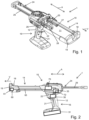
- FIG. 1 and Fig. 2 A preferred embodiment of a squeezing system 1 according to the invention is shown in Fig. 1 and Fig. 2 shown, where in Fig.1 a squeezing device 10 of the squeezing system 1 and in Fig.2 a cartridge device 40 of the squeezing system 1 is shown.
- the dispensing device 10 can basically be designed for dispensing single-component and, in the present case, multi-component masses, whereby the masses can be intended for filling, bonding or sealing or similar applications in the construction sector. Such and other masses are arranged in one or more cartridges of a cartridge device.
- the squeezing device 10 is designed to interact with a Fig.3 shown cartridge device 40, which has two containers designed as cartridges 41 and 42.
- the cartridge device 40 can be arranged in a receiving space 11 of a housing 12 of the dispensing device 10 and can contain, for example, a two-component mortar mass.
- a hardenable resin component can be arranged in one chamber or cartridge 41 of the cartridge device 40 and a hardener component can be arranged in the other chamber or cartridge 42 of the cartridge device 40, which is arranged separately from it in a reaction-inhibiting manner.
- the mass resulting from mixing the hardenable resin component and the hardener component is used, for example, as injection mortar for the chemical anchoring of, for example, metal elements in mineral substrates, such as in particular buildings made of brickwork, concrete or natural stone.
- the drill holes required for fastening the anchoring means are drilled into the mineral substrate, after which the hardenable resin component is mixed with the hardener component of the two-component mortar mass and introduced into the drill hole, whereupon the anchoring means to be fastened is inserted and adjusted and the mortar mass then hardens.
- the housing 12 of the dispensing device 10 extends in the present case essentially along an axial direction A and has a functional section 14 and a handling section 16.
- the functional section 14 essentially has the receiving space 11 and, at a processing-side distal end 18 of the functional section 14, a processing head 19 into which a dispensing opening of the cartridges 41, 42 extends. Masses dispensed from the cartridges 41, 42 are mixed in particular in a mixing area 49 of the cartridge device 40 and dispensed to a location to be processed at the processing-side distal end 18 of the functional section 14.
- the handling section 16 of the housing 12 has, in addition to a handle 21, an actuating switch 22 arranged in the area of the handle 21, which can be designed, for example, as a so-called MOSFET switch.
- a pressing device 24 is provided, which in the present case is designed with two pressing pistons 25, 26, which in the present case are firmly connected to one another via a push rod 29.
- Each pressing piston 25, 26 has a stamp 27 or 28 at its end facing the respective cartridge 41 or 42.
- a drive device shown here only schematically, is provided, in particular designed as an electric motor 30, by means of which the squeezing pistons 25, 26 can be displaced in the axial direction A.
- the squeezing pistons 25, 26 can also be operated by means of compressed air or by means of a hydraulic drive.
- the extrusion pistons 25, 26 can be moved together in the direction of the distal end 18 via the push rod 29 which can be driven by the electric motor 30 in a feed direction V.
- the electric motor 30 is here driven by a merely Fig.2 schematically shown and designed as a battery 31.
- the squeezing device 10 can also be mains-operated, wherein a plug can be provided that can be coupled to a power network.
- the squeezing device 10 also has a control device 33, which is designed to actuate the electric motor 30 in response to a user request by means of the actuation switch 22.
- the electric motor 30 can be put into different operating modes by the control device 33, wherein a first operating mode corresponds to a deactivation mode in which no current is supplied from the accumulator 31 to the electric motor 30 and actuation of the actuation switch 22 does not lead to a displacement of the push rod 29.
- a second operating mode corresponds to normal or regular operation of the electric motor 30 in which actuation of the actuation switch 22 by the user leads to a displacement of the extrusion pistons 25 and 26 in the feed direction V at a first speed.
- the electric motor 30 can in particular also be put into a third operating mode by the control device 33 in which actuation of the actuation switch 22 by the user leads to a displacement of the extrusion pistons 25 and 26 in the feed direction V at a second speed that is reduced compared to the first speed.
- the cartridges 41, 42 of the cartridge device 40 each have a substantially cylindrical base body 43 or 44 with a first end wall 45 or 46 and an opposite second end wall 47 or 48.
- a dispensing opening is provided on the first end wall 45 or 46, which are connected to one another via the mixing area 49.
- a dispensing device in the form of a spout can be connected to the mixing area 49, for example.
- the second end wall 47 or 48 is designed to interact with the stamp 27 or 28 of the respective squeezing piston 25 or 26, wherein when the squeezing piston 25 or 26 is displaced in the feed direction V in the direction of the first end wall 45 or 46, a volume of the base body 43 or 44 of the respective cartridge 41 or 42 is reduced, so that the respective mass in the cartridges 41 and 42 is discharged through the dispensing opening, mixed with one another in the mixing area 49 and pressed out via the dispensing device.
- the squeezing system 1 also has a transmission device 60, which has at least one sensor 61 arranged on the squeezing device 10 and a signal transmitter 62 arranged on the cartridge device 40.
- the transmission device 60 is wireless and can work using a variety of transmission principles. In particular, it is an RFID transmission device, but alternatively it can also be, for example, a Bluetooth transmission device, an NFC transmission device, a WiFi transmission device, a QR transmission device, a DMC transmission device, a WLAN transmission device, a ZigBee transmission device, a Wibree transmission device, a WiMAX transmission device, an IrDA transmission device or a transmission device that works using optical radio.
- the signal generator 62 is arranged in the present case on a front side 50 of the mixing area 49 of the cartridge device 40, whereas the sensor 61 is arranged on the housing 12 of the dispensing device 10 in such a way that the signal generator 62 of the cartridge device 40 interacts with the sensor 61 when the cartridge device 40 is arranged in the prescribed manner in the receiving space 11 and signals can be transmitted from the signal generator 62 to the sensor 61.
- the sensor 61 is arranged, for example, in the region of a wall of the housing 12 delimiting a distal end region of the receiving region 11.
- the sensor 61 is coupled to the control device 33 by means of a further transmission device 65, wherein the further transmission device 65 can be designed wirelessly or wired.
- the further transmission device 65 can be designed on the basis of the same transmission mechanisms as the transmission device 60.
- Fig.4 an embodiment of a method according to the invention for operating the squeezing system 1 is shown, wherein the method can be used to determine, for example, whether a compatible system consisting of a squeezing device 10 and a cartridge device 40 is present. This can reliably prevent damage to both the squeezing device 10 and the cartridge device 40. Furthermore, the risk of damage as a result of incorrect operation can be reduced or prevented, for example.
- step S1 the cartridge device 40 is inserted into the receiving space 11.
- step S2 the signal generator 62 of the cartridge device 40 sends out a first signal, which in particular identifies the cartridge device 40 in terms of type, size, shape and the like.
- the cartridge device 40 in this case also sends out a third signal, which includes, for example, a shelf life of the cartridge device 40, a permissible temperature range of the ambient area for processing or the like.
- the signals sent out by the cartridge device 40 are received by the sensor 61 of the dispensing device 10 in step S3 when the cartridge device 40 is arranged in the receiving space 11 in the prescribed manner.
- step S4 second signals corresponding to the first signal and the third signal or generated from the first signal and the third signal are sent from the sensor 61 to the control device 33.
- the second signal correlating with the third signal is compared, for example, with a current ambient temperature determined by a temperature sensor, and if the current ambient temperature is within a permissible temperature range for the cartridge device 40, the process continues with query step S6.
- query step S5 can be used to compare whether the current date is before the permissible expiration date of the cartridge device 40. If the result is positive, the process continues with query step S6.
- the electric motor 30 is set to the first operating mode by the control device 33 in step S7, i.e. the electric motor 30 remains in the first operating mode if it was already in this mode before, or the electric motor 30 is transferred to the first operating mode if it was previously in a different operating mode.
- actuation of the actuation switch 22 does not lead to a displacement of the push rod 29 and thus of the squeezing pistons 25 and 26.
- the second signal correlating with the first signal is compared with values stored in the control device 33, for example in the form of a look-up table, or verified using an algorithm stored in the control device 33. If the query result of the comparison or verification is positive, the electric motor 30 is transferred by the control device 33 in step S8 to the second operating mode, whereas if the query result in query step S6 is negative, the electric motor 30 is transferred to the third operating mode in step S9. Alternatively, it can also be provided that the electric motor 30 is transferred to the first operating mode in step S9. In the second operating mode of the electric motor 30, a user request by actuating the actuation switch 22 to a displacement of the push rod 29 and thus to a displacement of the squeezing pistons 25, 26.
- step S10 a query is made as to whether the relevant framework conditions to be defined have changed to a specified extent. If the query result is positive, the process continues with step S1. If the query result is negative, the process ends with step E.
- the squeezing device 10 has in particular an output device 70, which is designed, for example, to output a warning signal in an optical, acoustic and/or haptic manner when the electric motor 30 is set to the first operating mode by the control device 33 in step S7 and/or transferred to the third operating mode in step S9.
- the control device 33 can also have a storage device 72, which is designed to at least temporarily store the first signal, the second signal and/or the third signal, and which can be read out via an output device. This makes it easy to evaluate usage information of the squeezing system 1.
Landscapes
- Engineering & Computer Science (AREA)
- Mechanical Engineering (AREA)
- Coating Apparatus (AREA)
- Application Of Or Painting With Fluid Materials (AREA)
- Devices For Dispensing Beverages (AREA)
- Feeding, Discharge, Calcimining, Fusing, And Gas-Generation Devices (AREA)
- Containers And Packaging Bodies Having A Special Means To Remove Contents (AREA)
Claims (14)
- Procédé pour faire fonctionner un système d'expulsion par pression (1) comprenant un appareil d'expulsion par pression (10) et un dispositif à cartouche (40), dans lequel l'appareil d'expulsion par pression (10) présente au moins un espace de réception (11) pour la réception du dispositif à cartouche (40), au moins un dispositif d'expulsion par pression (24), un dispositif de commande (33), un dispositif d'entraînement (30) et une alimentation en énergie (31),dans lequel le procédé comprend les étapes suivantes :- introduction du dispositif à cartouche dans l'au moins un espace de réception (S1) ;- émission d'au moins un premier signal par un générateur de signaux (62) du dispositif à cartouche (40) (S2) ;- réception de l'au moins un signal du dispositif à cartouche (40) au moyen d'au moins un capteur (61) de l'appareil d'expulsion par pression (10) (S3) ;- envoi d'un deuxième signal du capteur (61) au dispositif de commande (33) (S4) ;- passage du dispositif d'entraînement (30) d'un premier mode de fonctionnement à un deuxième mode de fonctionnement (S8) lorsque le deuxième signal correspond à une valeur enregistrée dans le dispositif de commande (33) ou lorsqu'un algorithme enregistré dans le dispositif de commande (33) vérifie le deuxième signal (S6), ou- dans le cas contraire, passage du dispositif d'entraînement dans un troisième mode de fonctionnement (S9),caractérisé par l'émission d'au moins un troisième signal par le générateur de signaux (62) du dispositif à cartouche (40), lequel troisième signal règle (S7) le dispositif d'entraînement (30) dans le premier mode de fonctionnement, lorsque le troisième signal est supérieur à une valeur seuil (S5) enregistrée dans le dispositif de commande (33).
- Procédé selon la revendication 1,
caractérisé en ce que le premier mode de fonctionnement du dispositif d'entraînement (30) est un mode de désactivation dans lequel aucun courant n'est fourni par l'alimentation en énergie (31) au dispositif d'entraînement (30). - Procédé selon l'une des revendications 1 ou 2,
caractérisé en ce que le troisième mode de fonctionnement du dispositif d'entraînement (30) correspond au premier mode de fonctionnement du dispositif d'entraînement (30). - Procédé selon la revendication 3,
caractérisé en ce que le maintien du dispositif d'entraînement (30) dans le premier mode de fonctionnement est obtenu par une interruption du chemin d'énergie entre l'alimentation en énergie (31) et le dispositif d'entraînement (30). - Procédé selon l'une des revendications 1 ou 2,
caractérisé en ce que, dans le troisième mode de fonctionnement du dispositif d'entraînement (30), le dispositif d'expulsion par pression (24) est approvisionné avec une avance dans une première direction (V) à une première vitesse qui est inférieure à une vitesse d'avance du dispositif d'expulsion par pression (24) dans la première direction (V) dans le deuxième mode de fonctionnement du dispositif d'entraînement (30). - Procédé selon l'une des revendications 1 à 5,
caractérisé par l'émission d'un signal d'avertissement par un générateur de signaux d'avertissement (70) dans le troisième mode de fonctionnement du dispositif d'entraînement (30). - Procédé selon l'une des revendications 1 à 6,
caractérisé par l'émission d'un signal d'avertissement par un générateur de signaux d'avertissement (70) lorsque le troisième signal dépasse une valeur seuil enregistrée dans le dispositif de commande (33). - Système d'expulsion par pression (1) pour la mise en oeuvre d'un procédé selon l'une des revendications 1 à 7, comportant un appareil d'expulsion par pression (10) et un dispositif à cartouche (40), dans lequel l'appareil d'expulsion par pression (10) présente au moins un espace de réception (11) pour la réception du dispositif à cartouche (40), au moins un dispositif d'expulsion par pression (24), un dispositif de commande (33), un dispositif d'entraînement (30) et une alimentation en énergie (31), et dans lequel le dispositif à cartouche (40) présente un générateur de signaux (62) pour l'émission d'au moins un signal et l'appareil d'expulsion par pression (10) présente au moins un capteur (61) pour la réception d'au moins un signal du générateur de signaux (62).
- Système d'expulsion par pression selon la revendication 8,
caractérisé en ce qu'un dispositif de transmission (60) sans fil comportant un générateur de signaux (62) associé au dispositif à cartouche (40) et au moins un capteur (61) associé à l'appareil d'expulsion par pression (10) sont prévus. - Système d'expulsion par pression selon la revendication 9,
caractérisé en ce que le dispositif de transmission (60) sans fil est un dispositif de transmission optique ou un dispositif de transmission radio et est réalisé en particulier comme dispositif de transmission RFID, comme dispositif de transmission Bluetooth, comme dispositif de transmission CCP, comme dispositif de transmission WiFi, comme dispositif de transmission QR, comme dispositif de transmission DMC, comme dispositif de transmission WLAN, comme dispositif de transmission ZigBee, comme dispositif de transmission Wibree, comme dispositif de transmission WiMAX, comme dispositif de transmission IrDA ou comme dispositif de transmission fonctionnant selon un faisceau hertzien optique. - Système d'expulsion par pression selon l'une des revendications 9 ou 10,
caractérisé en ce que l'au moins un capteur (61) est connecté au dispositif de commande (33) au moyen d'un autre dispositif de transmission (65), dans lequel l'autre dispositif de transmission (65) est réalisé avec ou sans fil. - Système d'expulsion par pression selon la revendication 11,
caractérisé en ce que l'autre dispositif de transmission (65) est réalisé comme dispositif de transmission RFID, comme dispositif de transmission Bluetooth, comme dispositif de transmission CCP, comme dispositif de transmission WiFi, comme dispositif de transmission QR, comme dispositif de transmission DMC, comme dispositif de transmission WLAN, comme dispositif de transmission ZigBee, comme dispositif de transmission Wibree, comme dispositif de transmission WiMAX, comme dispositif de transmission IrDA ou comme dispositif de transmission fonctionnant selon un faisceau hertzien optique. - Système d'expulsion par pression selon l'une des revendications 8 à 12,
caractérisé en ce qu'un dispositif de distribution (70) est prévu sur un boîtier (12) de l'appareil d'expulsion par pression (10). - Système d'expulsion par pression selon l'une des revendications 8 à 13,
caractérisé en ce que l'appareil d'expulsion par pression (10) présente au moins un dispositif de mémoire lisible (72) réalisé pour mémoriser au moins temporairement le premier signal, le deuxième signal et/ou le troisième signal.
Applications Claiming Priority (2)
| Application Number | Priority Date | Filing Date | Title |
|---|---|---|---|
| EP18212571.6A EP3666400A1 (fr) | 2018-12-14 | 2018-12-14 | Procédé de fonctionnement d'un système de pression et système de pression |
| PCT/EP2019/082355 WO2020120112A1 (fr) | 2018-12-14 | 2019-11-25 | Procédé pour faire fonctionner un système de distribution par pression et système de distribution par pression |
Publications (2)
| Publication Number | Publication Date |
|---|---|
| EP3894096A1 EP3894096A1 (fr) | 2021-10-20 |
| EP3894096B1 true EP3894096B1 (fr) | 2024-08-28 |
Family
ID=64665554
Family Applications (2)
| Application Number | Title | Priority Date | Filing Date |
|---|---|---|---|
| EP18212571.6A Withdrawn EP3666400A1 (fr) | 2018-12-14 | 2018-12-14 | Procédé de fonctionnement d'un système de pression et système de pression |
| EP19806250.7A Active EP3894096B1 (fr) | 2018-12-14 | 2019-11-25 | Procédé de fonctionnement d'un système de pression et système de pression |
Family Applications Before (1)
| Application Number | Title | Priority Date | Filing Date |
|---|---|---|---|
| EP18212571.6A Withdrawn EP3666400A1 (fr) | 2018-12-14 | 2018-12-14 | Procédé de fonctionnement d'un système de pression et système de pression |
Country Status (8)
| Country | Link |
|---|---|
| US (1) | US11673160B2 (fr) |
| EP (2) | EP3666400A1 (fr) |
| JP (1) | JP7429495B2 (fr) |
| AU (1) | AU2019396381B2 (fr) |
| CA (1) | CA3118180A1 (fr) |
| ES (1) | ES2992831T3 (fr) |
| PL (1) | PL3894096T3 (fr) |
| WO (1) | WO2020120112A1 (fr) |
Families Citing this family (5)
| Publication number | Priority date | Publication date | Assignee | Title |
|---|---|---|---|---|
| EP3666401A1 (fr) * | 2018-12-14 | 2020-06-17 | Hilti Aktiengesellschaft | Procédé de fonctionnement d'un système de pression et système de pression |
| AU2019426842B2 (en) * | 2019-01-28 | 2025-12-18 | Discovery Purchaser Corporation | Applicator for pesticides |
| EP4011505A1 (fr) | 2020-12-10 | 2022-06-15 | Hilti Aktiengesellschaft | Distributeur et procédé de commande du distributeur |
| EP4011507A1 (fr) | 2020-12-10 | 2022-06-15 | Hilti Aktiengesellschaft | Distributeur et procédé de commande du distributeur |
| EP4011506A1 (fr) | 2020-12-10 | 2022-06-15 | Hilti Aktiengesellschaft | Distributeur et procédé de commande du distributeur |
Citations (1)
| Publication number | Priority date | Publication date | Assignee | Title |
|---|---|---|---|---|
| WO2020002596A1 (fr) * | 2018-06-29 | 2020-01-02 | Sulzer Mixpac Ag | Système de commande de distribution, procédé de commande d'un dispositif de distribution et arrière-plan de programme d'ordinateur |
Family Cites Families (16)
| Publication number | Priority date | Publication date | Assignee | Title |
|---|---|---|---|---|
| US5556009A (en) * | 1994-07-18 | 1996-09-17 | Wagner Spray Tech Corporation | Adjustable constant pressure caulk gun |
| EP2382941A1 (fr) * | 2010-04-29 | 2011-11-02 | 3M Innovative Properties Company | Système comprenant un dispositif de mélange et de distribution et un récipient pour matériaux |
| DE102011075873A1 (de) * | 2011-05-16 | 2012-11-22 | Hilti Aktiengesellschaft | Auspressgerät und Gebinde für ein Auspressgerät |
| US8573450B2 (en) * | 2011-08-15 | 2013-11-05 | Techway Industrial Co., Ltd. | Electrical caulking gun |
| US9239428B2 (en) * | 2011-09-28 | 2016-01-19 | Ksaria Corporation | Epoxy dispensing system and dispensing tip used therewith |
| JP6145114B2 (ja) * | 2012-01-12 | 2017-06-07 | スルザー ミックスパック デンマーク アクティーゼルスカブ | モータ付き粘性材料ディスペンサ |
| BR112014016964B1 (pt) * | 2012-01-12 | 2020-09-01 | Sulzer Mixpac Ag | Dispensador motorizado de material viscoso e método de operar um dispensador |
| US8957608B2 (en) * | 2013-01-15 | 2015-02-17 | Techway Industrial Co., Ltd. | Motor-driving device of an electric caulking gun |
| US9242267B2 (en) * | 2013-01-31 | 2016-01-26 | Owens Corning Intellectual Capital, Llc | Method and apparatus for mixing and applying material |
| EP2923774B1 (fr) * | 2014-03-24 | 2019-02-13 | Sulzer Mixpac AG | Distributeur |
| EP3111880B1 (fr) * | 2015-07-02 | 2019-03-27 | Ivoclar Vivadent AG | Dispositif d'injection |
| US9862001B2 (en) * | 2015-12-31 | 2018-01-09 | Sulzer Mixpac Ag | Dispensing device |
| CA3010608C (fr) * | 2016-01-05 | 2024-09-17 | Gojo Industries, Inc. | Systemes et procedes pour surveiller et reguler la recharge de fluide de distributeur |
| DE102016213882A1 (de) * | 2016-07-28 | 2018-02-01 | Robert Bosch Gmbh | Mobile Dosiervorrichtung |
| US10334837B1 (en) * | 2018-02-14 | 2019-07-02 | Bayer Cropscience Lp | Applicator for pesticides with trigger and cartridge |
| US10894272B2 (en) * | 2018-06-29 | 2021-01-19 | Sulzer Mixpac Ag | Dispensing control system |
-
2018
- 2018-12-14 EP EP18212571.6A patent/EP3666400A1/fr not_active Withdrawn
-
2019
- 2019-11-25 PL PL19806250.7T patent/PL3894096T3/pl unknown
- 2019-11-25 AU AU2019396381A patent/AU2019396381B2/en active Active
- 2019-11-25 JP JP2021530051A patent/JP7429495B2/ja active Active
- 2019-11-25 US US17/298,722 patent/US11673160B2/en active Active
- 2019-11-25 EP EP19806250.7A patent/EP3894096B1/fr active Active
- 2019-11-25 WO PCT/EP2019/082355 patent/WO2020120112A1/fr not_active Ceased
- 2019-11-25 ES ES19806250T patent/ES2992831T3/es active Active
- 2019-11-25 CA CA3118180A patent/CA3118180A1/fr active Pending
Patent Citations (1)
| Publication number | Priority date | Publication date | Assignee | Title |
|---|---|---|---|---|
| WO2020002596A1 (fr) * | 2018-06-29 | 2020-01-02 | Sulzer Mixpac Ag | Système de commande de distribution, procédé de commande d'un dispositif de distribution et arrière-plan de programme d'ordinateur |
Also Published As
| Publication number | Publication date |
|---|---|
| US11673160B2 (en) | 2023-06-13 |
| ES2992831T3 (en) | 2024-12-18 |
| JP7429495B2 (ja) | 2024-02-08 |
| AU2019396381B2 (en) | 2025-01-16 |
| PL3894096T3 (pl) | 2025-02-24 |
| CA3118180A1 (fr) | 2020-06-18 |
| AU2019396381A1 (en) | 2021-05-27 |
| US20220048064A1 (en) | 2022-02-17 |
| EP3894096A1 (fr) | 2021-10-20 |
| WO2020120112A1 (fr) | 2020-06-18 |
| JP2022510192A (ja) | 2022-01-26 |
| EP3666400A1 (fr) | 2020-06-17 |
Similar Documents
| Publication | Publication Date | Title |
|---|---|---|
| EP3894096B1 (fr) | Procédé de fonctionnement d'un système de pression et système de pression | |
| EP3894095A1 (fr) | Procédé pour faire fonctionner un système de distribution par pression et système de distribution par pression | |
| EP3632567A1 (fr) | Dispositif de pipetage pour pipeter de petits volumes liquides | |
| DE112012007147T5 (de) | Steuersysteme für Ventilaktuatoren, Ventilaktuatoren und verwandte Verfahren | |
| EP1732456B1 (fr) | Appareil pour chirurgie au jet d'eau | |
| EP3074825B1 (fr) | Système équipé d'une vanne et procédé de fonctionnement d'un tel système | |
| DE2245413B2 (de) | Pipette | |
| EP0999432A2 (fr) | Procédé d' opération d' un système de dosage électronique et système de dosage pour la mise en oeuvre du procédé | |
| EP2314384A1 (fr) | Dispositif de compression | |
| EP3820614A1 (fr) | Dispositif de pipetage pour pipetage par impulsions par déplacement du piston de pipetage régulé sur la base d'une détection de la position de piston | |
| DE102011117963A1 (de) | Fluidtransfervorrichtung | |
| DE102020115024A1 (de) | Handgerät mit Sensoreinrichtung zum Charakterisieren eines bearbeiteten Untergrunds | |
| DE102015218508A1 (de) | Messwertübertragungssystem für handgeführte Metrologieinstrumente | |
| CH712010A1 (de) | Pipette mit Abwurfmechanismus für Pipettenspitzen. | |
| DE102015210716B4 (de) | Positionssensor sowie Verfahren zum Betreiben eines Positionssensors | |
| DE10257414B4 (de) | Handdispenser mit elektromotorischem Antrieb | |
| EP3718501B1 (fr) | Dispositif d'extrusion pour matières dentaires | |
| EP4484020A1 (fr) | Procédé de fonctionnement d'un appareil d'extrusion et appareil d'extrusion | |
| EP2452742A1 (fr) | Dispositif de contrôle pour un dispositif de mélange | |
| EP4458294B1 (fr) | Dispositif de distribution de ciment osseux par robot chirurgical | |
| EP2338589A1 (fr) | Procédé et dispositif de préparation de masses à partir d'au moins deux composants | |
| DE102008009665B3 (de) | Möbel mit Datenübertragungsschnittstelle | |
| DE102010047305A1 (de) | Misch-, Rühr- oder Dispergierverfahren und Vorrichtung hierfür | |
| EP3891567B1 (fr) | Procédé de fonctionnement d'un système et système | |
| DE10349031A1 (de) | Verfahren zur Betätigung eines Heckklappenantriebs eines Kraftfahrzeuges |
Legal Events
| Date | Code | Title | Description |
|---|---|---|---|
| STAA | Information on the status of an ep patent application or granted ep patent |
Free format text: STATUS: UNKNOWN |
|
| STAA | Information on the status of an ep patent application or granted ep patent |
Free format text: STATUS: THE INTERNATIONAL PUBLICATION HAS BEEN MADE |
|
| PUAI | Public reference made under article 153(3) epc to a published international application that has entered the european phase |
Free format text: ORIGINAL CODE: 0009012 |
|
| STAA | Information on the status of an ep patent application or granted ep patent |
Free format text: STATUS: REQUEST FOR EXAMINATION WAS MADE |
|
| 17P | Request for examination filed |
Effective date: 20210714 |
|
| AK | Designated contracting states |
Kind code of ref document: A1 Designated state(s): AL AT BE BG CH CY CZ DE DK EE ES FI FR GB GR HR HU IE IS IT LI LT LU LV MC MK MT NL NO PL PT RO RS SE SI SK SM TR |
|
| DAV | Request for validation of the european patent (deleted) | ||
| DAX | Request for extension of the european patent (deleted) | ||
| GRAP | Despatch of communication of intention to grant a patent |
Free format text: ORIGINAL CODE: EPIDOSNIGR1 |
|
| STAA | Information on the status of an ep patent application or granted ep patent |
Free format text: STATUS: GRANT OF PATENT IS INTENDED |
|
| INTG | Intention to grant announced |
Effective date: 20240619 |
|
| GRAS | Grant fee paid |
Free format text: ORIGINAL CODE: EPIDOSNIGR3 |
|
| GRAA | (expected) grant |
Free format text: ORIGINAL CODE: 0009210 |
|
| STAA | Information on the status of an ep patent application or granted ep patent |
Free format text: STATUS: THE PATENT HAS BEEN GRANTED |
|
| AK | Designated contracting states |
Kind code of ref document: B1 Designated state(s): AL AT BE BG CH CY CZ DE DK EE ES FI FR GB GR HR HU IE IS IT LI LT LU LV MC MK MT NL NO PL PT RO RS SE SI SK SM TR |
|
| REG | Reference to a national code |
Ref country code: GB Ref legal event code: FG4D Free format text: NOT ENGLISH |
|
| REG | Reference to a national code |
Ref country code: CH Ref legal event code: EP |
|
| REG | Reference to a national code |
Ref country code: DE Ref legal event code: R096 Ref document number: 502019012012 Country of ref document: DE |
|
| REG | Reference to a national code |
Ref country code: IE Ref legal event code: FG4D Free format text: LANGUAGE OF EP DOCUMENT: GERMAN |
|
| REG | Reference to a national code |
Ref country code: ES Ref legal event code: FG2A Ref document number: 2992831 Country of ref document: ES Kind code of ref document: T3 Effective date: 20241218 |
|
| REG | Reference to a national code |
Ref country code: LT Ref legal event code: MG9D |
|
| PG25 | Lapsed in a contracting state [announced via postgrant information from national office to epo] |
Ref country code: NO Free format text: LAPSE BECAUSE OF FAILURE TO SUBMIT A TRANSLATION OF THE DESCRIPTION OR TO PAY THE FEE WITHIN THE PRESCRIBED TIME-LIMIT Effective date: 20241128 |
|
| PG25 | Lapsed in a contracting state [announced via postgrant information from national office to epo] |
Ref country code: NL Free format text: LAPSE BECAUSE OF FAILURE TO SUBMIT A TRANSLATION OF THE DESCRIPTION OR TO PAY THE FEE WITHIN THE PRESCRIBED TIME-LIMIT Effective date: 20240828 Ref country code: FI Free format text: LAPSE BECAUSE OF FAILURE TO SUBMIT A TRANSLATION OF THE DESCRIPTION OR TO PAY THE FEE WITHIN THE PRESCRIBED TIME-LIMIT Effective date: 20240828 Ref country code: GR Free format text: LAPSE BECAUSE OF FAILURE TO SUBMIT A TRANSLATION OF THE DESCRIPTION OR TO PAY THE FEE WITHIN THE PRESCRIBED TIME-LIMIT Effective date: 20241129 Ref country code: PT Free format text: LAPSE BECAUSE OF FAILURE TO SUBMIT A TRANSLATION OF THE DESCRIPTION OR TO PAY THE FEE WITHIN THE PRESCRIBED TIME-LIMIT Effective date: 20241230 |
|
| PG25 | Lapsed in a contracting state [announced via postgrant information from national office to epo] |
Ref country code: BG Free format text: LAPSE BECAUSE OF FAILURE TO SUBMIT A TRANSLATION OF THE DESCRIPTION OR TO PAY THE FEE WITHIN THE PRESCRIBED TIME-LIMIT Effective date: 20240828 |
|
| PG25 | Lapsed in a contracting state [announced via postgrant information from national office to epo] |
Ref country code: LV Free format text: LAPSE BECAUSE OF FAILURE TO SUBMIT A TRANSLATION OF THE DESCRIPTION OR TO PAY THE FEE WITHIN THE PRESCRIBED TIME-LIMIT Effective date: 20240828 |
|
| REG | Reference to a national code |
Ref country code: NL Ref legal event code: MP Effective date: 20240828 |
|
| PG25 | Lapsed in a contracting state [announced via postgrant information from national office to epo] |
Ref country code: IS Free format text: LAPSE BECAUSE OF FAILURE TO SUBMIT A TRANSLATION OF THE DESCRIPTION OR TO PAY THE FEE WITHIN THE PRESCRIBED TIME-LIMIT Effective date: 20241228 |
|
| PG25 | Lapsed in a contracting state [announced via postgrant information from national office to epo] |
Ref country code: HR Free format text: LAPSE BECAUSE OF FAILURE TO SUBMIT A TRANSLATION OF THE DESCRIPTION OR TO PAY THE FEE WITHIN THE PRESCRIBED TIME-LIMIT Effective date: 20240828 |
|
| PG25 | Lapsed in a contracting state [announced via postgrant information from national office to epo] |
Ref country code: RS Free format text: LAPSE BECAUSE OF FAILURE TO SUBMIT A TRANSLATION OF THE DESCRIPTION OR TO PAY THE FEE WITHIN THE PRESCRIBED TIME-LIMIT Effective date: 20241128 |
|
| PG25 | Lapsed in a contracting state [announced via postgrant information from national office to epo] |
Ref country code: RS Free format text: LAPSE BECAUSE OF FAILURE TO SUBMIT A TRANSLATION OF THE DESCRIPTION OR TO PAY THE FEE WITHIN THE PRESCRIBED TIME-LIMIT Effective date: 20241128 Ref country code: PT Free format text: LAPSE BECAUSE OF FAILURE TO SUBMIT A TRANSLATION OF THE DESCRIPTION OR TO PAY THE FEE WITHIN THE PRESCRIBED TIME-LIMIT Effective date: 20241230 Ref country code: NO Free format text: LAPSE BECAUSE OF FAILURE TO SUBMIT A TRANSLATION OF THE DESCRIPTION OR TO PAY THE FEE WITHIN THE PRESCRIBED TIME-LIMIT Effective date: 20241128 Ref country code: NL Free format text: LAPSE BECAUSE OF FAILURE TO SUBMIT A TRANSLATION OF THE DESCRIPTION OR TO PAY THE FEE WITHIN THE PRESCRIBED TIME-LIMIT Effective date: 20240828 Ref country code: LV Free format text: LAPSE BECAUSE OF FAILURE TO SUBMIT A TRANSLATION OF THE DESCRIPTION OR TO PAY THE FEE WITHIN THE PRESCRIBED TIME-LIMIT Effective date: 20240828 Ref country code: IS Free format text: LAPSE BECAUSE OF FAILURE TO SUBMIT A TRANSLATION OF THE DESCRIPTION OR TO PAY THE FEE WITHIN THE PRESCRIBED TIME-LIMIT Effective date: 20241228 Ref country code: HR Free format text: LAPSE BECAUSE OF FAILURE TO SUBMIT A TRANSLATION OF THE DESCRIPTION OR TO PAY THE FEE WITHIN THE PRESCRIBED TIME-LIMIT Effective date: 20240828 Ref country code: GR Free format text: LAPSE BECAUSE OF FAILURE TO SUBMIT A TRANSLATION OF THE DESCRIPTION OR TO PAY THE FEE WITHIN THE PRESCRIBED TIME-LIMIT Effective date: 20241129 Ref country code: FI Free format text: LAPSE BECAUSE OF FAILURE TO SUBMIT A TRANSLATION OF THE DESCRIPTION OR TO PAY THE FEE WITHIN THE PRESCRIBED TIME-LIMIT Effective date: 20240828 Ref country code: BG Free format text: LAPSE BECAUSE OF FAILURE TO SUBMIT A TRANSLATION OF THE DESCRIPTION OR TO PAY THE FEE WITHIN THE PRESCRIBED TIME-LIMIT Effective date: 20240828 |
|
| PG25 | Lapsed in a contracting state [announced via postgrant information from national office to epo] |
Ref country code: SM Free format text: LAPSE BECAUSE OF FAILURE TO SUBMIT A TRANSLATION OF THE DESCRIPTION OR TO PAY THE FEE WITHIN THE PRESCRIBED TIME-LIMIT Effective date: 20240828 Ref country code: DK Free format text: LAPSE BECAUSE OF FAILURE TO SUBMIT A TRANSLATION OF THE DESCRIPTION OR TO PAY THE FEE WITHIN THE PRESCRIBED TIME-LIMIT Effective date: 20240828 Ref country code: RO Free format text: LAPSE BECAUSE OF FAILURE TO SUBMIT A TRANSLATION OF THE DESCRIPTION OR TO PAY THE FEE WITHIN THE PRESCRIBED TIME-LIMIT Effective date: 20240828 |
|
| PG25 | Lapsed in a contracting state [announced via postgrant information from national office to epo] |
Ref country code: EE Free format text: LAPSE BECAUSE OF FAILURE TO SUBMIT A TRANSLATION OF THE DESCRIPTION OR TO PAY THE FEE WITHIN THE PRESCRIBED TIME-LIMIT Effective date: 20240828 |
|
| PG25 | Lapsed in a contracting state [announced via postgrant information from national office to epo] |
Ref country code: CZ Free format text: LAPSE BECAUSE OF FAILURE TO SUBMIT A TRANSLATION OF THE DESCRIPTION OR TO PAY THE FEE WITHIN THE PRESCRIBED TIME-LIMIT Effective date: 20240828 |
|
| PG25 | Lapsed in a contracting state [announced via postgrant information from national office to epo] |
Ref country code: SK Free format text: LAPSE BECAUSE OF FAILURE TO SUBMIT A TRANSLATION OF THE DESCRIPTION OR TO PAY THE FEE WITHIN THE PRESCRIBED TIME-LIMIT Effective date: 20240828 |
|
| REG | Reference to a national code |
Ref country code: DE Ref legal event code: R097 Ref document number: 502019012012 Country of ref document: DE |
|
| PLBE | No opposition filed within time limit |
Free format text: ORIGINAL CODE: 0009261 |
|
| STAA | Information on the status of an ep patent application or granted ep patent |
Free format text: STATUS: NO OPPOSITION FILED WITHIN TIME LIMIT |
|
| PG25 | Lapsed in a contracting state [announced via postgrant information from national office to epo] |
Ref country code: MC Free format text: LAPSE BECAUSE OF FAILURE TO SUBMIT A TRANSLATION OF THE DESCRIPTION OR TO PAY THE FEE WITHIN THE PRESCRIBED TIME-LIMIT Effective date: 20240828 |
|
| PG25 | Lapsed in a contracting state [announced via postgrant information from national office to epo] |
Ref country code: LU Free format text: LAPSE BECAUSE OF NON-PAYMENT OF DUE FEES Effective date: 20241125 |
|
| 26N | No opposition filed |
Effective date: 20250530 |
|
| PG25 | Lapsed in a contracting state [announced via postgrant information from national office to epo] |
Ref country code: SE Free format text: LAPSE BECAUSE OF FAILURE TO SUBMIT A TRANSLATION OF THE DESCRIPTION OR TO PAY THE FEE WITHIN THE PRESCRIBED TIME-LIMIT Effective date: 20240828 |
|
| PG25 | Lapsed in a contracting state [announced via postgrant information from national office to epo] |
Ref country code: IE Free format text: LAPSE BECAUSE OF NON-PAYMENT OF DUE FEES Effective date: 20241125 |
|
| REG | Reference to a national code |
Ref country code: CH Ref legal event code: U11 Free format text: ST27 STATUS EVENT CODE: U-0-0-U10-U11 (AS PROVIDED BY THE NATIONAL OFFICE) Effective date: 20251201 |
|
| PGFP | Annual fee paid to national office [announced via postgrant information from national office to epo] |
Ref country code: DE Payment date: 20251119 Year of fee payment: 7 |
|
| PGFP | Annual fee paid to national office [announced via postgrant information from national office to epo] |
Ref country code: GB Payment date: 20251121 Year of fee payment: 7 |
|
| PGFP | Annual fee paid to national office [announced via postgrant information from national office to epo] |
Ref country code: AT Payment date: 20251120 Year of fee payment: 7 |
|
| PGFP | Annual fee paid to national office [announced via postgrant information from national office to epo] |
Ref country code: IT Payment date: 20251125 Year of fee payment: 7 |
|
| PGFP | Annual fee paid to national office [announced via postgrant information from national office to epo] |
Ref country code: FR Payment date: 20251126 Year of fee payment: 7 |
|
| PGFP | Annual fee paid to national office [announced via postgrant information from national office to epo] |
Ref country code: BE Payment date: 20251119 Year of fee payment: 7 |
|
| PGFP | Annual fee paid to national office [announced via postgrant information from national office to epo] |
Ref country code: CH Payment date: 20251201 Year of fee payment: 7 |
|
| PGFP | Annual fee paid to national office [announced via postgrant information from national office to epo] |
Ref country code: PL Payment date: 20251114 Year of fee payment: 7 |
|
| PGFP | Annual fee paid to national office [announced via postgrant information from national office to epo] |
Ref country code: ES Payment date: 20251229 Year of fee payment: 7 |
|
| PG25 | Lapsed in a contracting state [announced via postgrant information from national office to epo] |
Ref country code: HU Free format text: LAPSE BECAUSE OF FAILURE TO SUBMIT A TRANSLATION OF THE DESCRIPTION OR TO PAY THE FEE WITHIN THE PRESCRIBED TIME-LIMIT; INVALID AB INITIO Effective date: 20191125 |
|
| PG25 | Lapsed in a contracting state [announced via postgrant information from national office to epo] |
Ref country code: CY Free format text: LAPSE BECAUSE OF FAILURE TO SUBMIT A TRANSLATION OF THE DESCRIPTION OR TO PAY THE FEE WITHIN THE PRESCRIBED TIME-LIMIT; INVALID AB INITIO Effective date: 20191125 |