EP3666700A1 - Dispositif d'enroulement et de changement de bobine de matériau en forme de bande et procédé correspondant - Google Patents
Dispositif d'enroulement et de changement de bobine de matériau en forme de bande et procédé correspondant Download PDFInfo
- Publication number
- EP3666700A1 EP3666700A1 EP19000556.1A EP19000556A EP3666700A1 EP 3666700 A1 EP3666700 A1 EP 3666700A1 EP 19000556 A EP19000556 A EP 19000556A EP 3666700 A1 EP3666700 A1 EP 3666700A1
- Authority
- EP
- European Patent Office
- Prior art keywords
- winding
- winding shaft
- web
- central drive
- new
- Prior art date
- Legal status (The legal status is an assumption and is not a legal conclusion. Google has not performed a legal analysis and makes no representation as to the accuracy of the status listed.)
- Granted
Links
Images

Classifications
-
- B—PERFORMING OPERATIONS; TRANSPORTING
- B65—CONVEYING; PACKING; STORING; HANDLING THIN OR FILAMENTARY MATERIAL
- B65H—HANDLING THIN OR FILAMENTARY MATERIAL, e.g. SHEETS, WEBS, CABLES
- B65H19/00—Changing the web roll
- B65H19/22—Changing the web roll in winding mechanisms or in connection with winding operations
- B65H19/30—Lifting, transporting, or removing the web roll; Inserting core
-
- B—PERFORMING OPERATIONS; TRANSPORTING
- B65—CONVEYING; PACKING; STORING; HANDLING THIN OR FILAMENTARY MATERIAL
- B65H—HANDLING THIN OR FILAMENTARY MATERIAL, e.g. SHEETS, WEBS, CABLES
- B65H19/00—Changing the web roll
- B65H19/22—Changing the web roll in winding mechanisms or in connection with winding operations
- B65H19/26—Cutting-off the web running to the wound web roll
-
- B—PERFORMING OPERATIONS; TRANSPORTING
- B65—CONVEYING; PACKING; STORING; HANDLING THIN OR FILAMENTARY MATERIAL
- B65H—HANDLING THIN OR FILAMENTARY MATERIAL, e.g. SHEETS, WEBS, CABLES
- B65H19/00—Changing the web roll
- B65H19/22—Changing the web roll in winding mechanisms or in connection with winding operations
- B65H19/2207—Changing the web roll in winding mechanisms or in connection with winding operations the web roll being driven by a winding mechanism of the centre or core drive type
- B65H19/223—Changing the web roll in winding mechanisms or in connection with winding operations the web roll being driven by a winding mechanism of the centre or core drive type with roll supports being independently displaceable along a common path
-
- B—PERFORMING OPERATIONS; TRANSPORTING
- B65—CONVEYING; PACKING; STORING; HANDLING THIN OR FILAMENTARY MATERIAL
- B65H—HANDLING THIN OR FILAMENTARY MATERIAL, e.g. SHEETS, WEBS, CABLES
- B65H18/00—Winding webs
-
- B—PERFORMING OPERATIONS; TRANSPORTING
- B65—CONVEYING; PACKING; STORING; HANDLING THIN OR FILAMENTARY MATERIAL
- B65H—HANDLING THIN OR FILAMENTARY MATERIAL, e.g. SHEETS, WEBS, CABLES
- B65H18/00—Winding webs
- B65H18/08—Web-winding mechanisms
- B65H18/10—Mechanisms in which power is applied to web-roll spindle
-
- B—PERFORMING OPERATIONS; TRANSPORTING
- B65—CONVEYING; PACKING; STORING; HANDLING THIN OR FILAMENTARY MATERIAL
- B65H—HANDLING THIN OR FILAMENTARY MATERIAL, e.g. SHEETS, WEBS, CABLES
- B65H19/00—Changing the web roll
- B65H19/22—Changing the web roll in winding mechanisms or in connection with winding operations
- B65H19/2207—Changing the web roll in winding mechanisms or in connection with winding operations the web roll being driven by a winding mechanism of the centre or core drive type
-
- B—PERFORMING OPERATIONS; TRANSPORTING
- B65—CONVEYING; PACKING; STORING; HANDLING THIN OR FILAMENTARY MATERIAL
- B65H—HANDLING THIN OR FILAMENTARY MATERIAL, e.g. SHEETS, WEBS, CABLES
- B65H35/00—Delivering articles from cutting or line-perforating machines; Article or web delivery apparatus incorporating cutting or line-perforating devices, e.g. adhesive tape dispensers
- B65H35/02—Delivering articles from cutting or line-perforating machines; Article or web delivery apparatus incorporating cutting or line-perforating devices, e.g. adhesive tape dispensers from or with longitudinal slitters or perforators
-
- B—PERFORMING OPERATIONS; TRANSPORTING
- B65—CONVEYING; PACKING; STORING; HANDLING THIN OR FILAMENTARY MATERIAL
- B65H—HANDLING THIN OR FILAMENTARY MATERIAL, e.g. SHEETS, WEBS, CABLES
- B65H2301/00—Handling processes for sheets or webs
- B65H2301/40—Type of handling process
- B65H2301/41—Winding, unwinding
- B65H2301/413—Supporting web roll
- B65H2301/4135—Movable supporting means
- B65H2301/41352—Movable supporting means moving on linear path (including linear slot arrangement)
- B65H2301/413523—Movable supporting means moving on linear path (including linear slot arrangement) reciprocrating supporting means
-
- B—PERFORMING OPERATIONS; TRANSPORTING
- B65—CONVEYING; PACKING; STORING; HANDLING THIN OR FILAMENTARY MATERIAL
- B65H—HANDLING THIN OR FILAMENTARY MATERIAL, e.g. SHEETS, WEBS, CABLES
- B65H2301/00—Handling processes for sheets or webs
- B65H2301/40—Type of handling process
- B65H2301/41—Winding, unwinding
- B65H2301/417—Handling or changing web rolls
- B65H2301/418—Changing web roll
-
- B—PERFORMING OPERATIONS; TRANSPORTING
- B65—CONVEYING; PACKING; STORING; HANDLING THIN OR FILAMENTARY MATERIAL
- B65H—HANDLING THIN OR FILAMENTARY MATERIAL, e.g. SHEETS, WEBS, CABLES
- B65H2301/00—Handling processes for sheets or webs
- B65H2301/50—Auxiliary process performed during handling process
- B65H2301/51—Modifying a characteristic of handled material
- B65H2301/515—Cutting handled material
- B65H2301/5155—Cutting handled material longitudinally
-
- B—PERFORMING OPERATIONS; TRANSPORTING
- B65—CONVEYING; PACKING; STORING; HANDLING THIN OR FILAMENTARY MATERIAL
- B65H—HANDLING THIN OR FILAMENTARY MATERIAL, e.g. SHEETS, WEBS, CABLES
- B65H2403/00—Power transmission; Driving means
- B65H2403/90—Machine drive
- B65H2403/94—Other features of machine drive
- B65H2403/942—Bidirectional powered handling device
-
- B—PERFORMING OPERATIONS; TRANSPORTING
- B65—CONVEYING; PACKING; STORING; HANDLING THIN OR FILAMENTARY MATERIAL
- B65H—HANDLING THIN OR FILAMENTARY MATERIAL, e.g. SHEETS, WEBS, CABLES
- B65H2701/00—Handled material; Storage means
- B65H2701/10—Handled articles or webs
- B65H2701/17—Nature of material
- B65H2701/175—Plastic
- B65H2701/1752—Polymer film
Definitions
- the invention relates to a device for winding and changing the winding of web-shaped material, in particular tubular films or film webs, which have a machine housing with guides for a winding shaft guide, two independently drivable central drives for driving winding shafts, a drivable winding shaft guide, which cooperates with a central drive and these on the guides between a parking position and a winding position, a contact roller unit which interacts with the winding shaft driven by the respective central drive in the winding position, separating devices for separating the web-like material, winding shaft transport units for feeding new winding shafts for changing the winding shaft and a reel dispenser and a method for this
- Winders are used to wind up sheet-like materials, such as plastic films, paper webs, metal foils or textiles.
- the material webs to be wound come directly from the manufacturing process and are brought into rolls, so-called coils, for further processing.
- Winders also come for foils e.g. from blown film lines for use.
- tubular films are formed at high speeds and, after they have been laid flat, they have to be wound up continuously on rolls without the production speed being reduced in the system. If the winding has reached a predefined size, it has to be changed, this also happens without stopping the production of the endless material web or changing the production speed.
- Known winding devices include turret winders, contact winders and central winders.
- a turret winder In a turret winder, one or two opposite turntables are rotatably mounted in a machine frame, which accommodate at least two rotatably mounted winding stations.
- a first winding station In operation, a first winding station is in the winding position and a second winding station is in a loading or unloading position in order to take up a new winding shaft or to deliver a finished winding. If the winding has reached its target size in the winding position, the first and the second winding point change their position by turning the turntable and the next winding can be wound up.
- the disadvantage here is that a large installation space is required for large winding diameters.
- winders with a linear movement of the winding stations including contact and central winders
- the winding to be wound is pressed against a driven contact roller, the winding is not driven separately.
- a so-called pre-winding point is necessary for these winders.
- the winding is driven centrally in the winding station. It can also be pressed against the contact roller or operated with a gap to the contact roller.
- a disadvantage of the latter two winders is that a transfer of the roll from the pre-winding point to the winding point is necessary when changing the reel.
- the pressure of the roll against the contact roller is not defined, so that different winding conditions arise.
- Winders are designed for left winding, right winding, or both.
- the winding direction of the web-shaped material depends on the subsequent process steps and on which side of the film must be on top for this process step.
- the pretreated side (corona) which is printed in a subsequent process step, can be wound inside or outside.
- the arrangement of the sealing layer in the coextrusion composite is independent of a required interior or outside arrangement during winding.
- the winding shaft then has the corresponding direction of rotation.
- a central winder In the DE 44 28 249 a central winder is disclosed.
- the winding device has two winding points arranged in a winding frame, which work in conjunction with a contact roller.
- the winding shafts of the two winding stations are each driven independently of motors.
- the winding stations can be moved on horizontal guide rails between the winding station and the delivery point for the finished winding.
- the contact roller is motor driven and can be lowered.
- When changing the winding station it is moved vertically downwards between the winding position and a parking position.
- the new winding shaft is inserted in the idle state, while the second winding shaft is in the operating state.
- a disadvantage of this design is that the winding shaft bearing requires an additional drive.
- This design of a central winder requires a defined winding direction, depending on the requirement, it is not possible to choose between right or left winding.
- Films are structured differently with regard to the number of layers and the types of material of the layers. They do not have to be symmetrical in their layer structure. Each blown film has a tube inside and a tube outside. When winding, it is desirable that, depending on the type of film layers and the type of further processing of the film, a special side is on the outside or inside. To make this possible, it is important that winders are designed to be clockwise and counterclockwise.
- the invention is therefore based on the object of providing a solution which makes it possible to provide a winder which enables both left-hand and right-hand winding, and the winder is designed without a pre-winding point.
- the winder according to the invention has a winding point arranged in a machine housing.
- This winding station has two central drives that are used alternately.
- the central drives are arranged one on each side of the machine housing. These interact with a driven winding shaft guide.
- the respective central drive is coupled to the driven winding shaft guide and moved between a parking position and a winding position on guides.
- the central drives are used alternately.
- the central drive in use is coupled to the winding shaft guide, the second central drive is firmly coupled to its waiting position.
- the central drives are arranged on the outside of the machine frame and cooperate with the winding shaft guide arranged inside, which moves on essentially horizontal guides, ideally on horizontal guides.
- the winding shaft also lies on a support which is arranged parallel and above the winding shaft guide.
- the central drive is preferably coupled into the waiting position on the machine housing or a separate frame.
- a contact roller unit In the winding position, a contact roller unit interacts with the winding shaft or the winding.
- the contact roller unit is designed to be movable, e.g. pneumatic or electric. It can be moved essentially horizontally between the winding position and a contact roller parking position.
- the contact roller unit comprises the contact roller, a guide and the contact pressure. Alternatively, the winding can also be wound up with a gap, then the contact roller does not press against the winding, the film runs over the contact roller.
- Separating units are arranged above and below the contact roller unit. They have two functions. On the one hand, they raise or lower the film web when changing the winding to bring the new winding shaft into the winding start position, and on the other hand, they separate the film web during the winding shaft changing process.
- the separation and lifting can also be carried out in separate devices, so that a lifting or lowering unit and a separate separation unit are arranged above and below the contact roller unit.
- the device also has a winding shaft transport unit for the newly inserted winding shafts. It is designed essentially vertically and is arranged in the area between the winding shaft guide and the contact roller unit. Depending on the winding direction, the new winding shaft is transported from above or below via the winding shaft transport unit to the winding level above or below the film web.
- the new winding shaft is moved from below to the winding level using the winding shaft transport unit.
- the winding shaft is inserted into the winding shaft transport unit from above and moved down to the winding level.
- the new winding shafts can be transported via further winding shaft transport units to the first-mentioned winding shaft transport unit and transferred to the latter so that the latter transports them in the direction of the winding plane.
- the winding shafts are fed laterally into the machine and placed in the winding shaft transport unit.
- a winding shaft is received by a first central drive and the shaft winding guide in winding operation.
- the central drive drives the winding shaft and the film web, which is guided to the winding shaft via a contact roller, is wound on the winding shaft.
- the contact roller is pressed onto the winding.
- the contact roller is designed to be movable. As the diameter increases, the winding moves with the Central drive and the winding shaft guide in the direction of the roll output device, away from the contact roller.
- the contact roller presses permanently against the roll, so that no air is wrapped in it, the film does not run and can therefore ensure uniform roll quality with a defined contact pressure.
- the winding is wound up until the target diameter is reached.
- the winding change is prepared. First, the winding shaft feed and the winding shaft change for the case of right winding are described. A new winding shaft is inserted into the winding shaft transport device and guided upwards into a first parking position in front of the winding level.
- the finished roll with the first central drive and the winding shaft guide is moved in the direction of the storage arms of the roll output device.
- This movement is achieved by drives on the winding shaft guide.
- the central drive In the front position, the central drive uncouples from the winding shaft guide and is firmly coupled to its end position, for example to the machine housing wall.
- the central drive continues to drive the winding.
- the contact roller unit moves a little to the rear, away from the winding position.
- the second central drive on the opposite side of the first central drive, decouples from its parking position and couples with the winding shaft guide.
- the winding shaft guide and the second central drive coupled to it move in the direction of the contact roller unit to the winding position.
- the winding position is not a fixed location, but is the position in which the central drive, in cooperation with the contact roller, winds the web-like material onto the winding.
- the position moves with increasing winding diameter on the guides in the direction of the reel dispenser.
- the new winding shaft is now moved with the winding shaft transport unit from the first parking position upwards in the direction of the winding plane to a second parking position.
- the lower separating device is pivoted into the film run as a lifting device and the film web is raised to make room for the new winding shaft.
- the winding shaft guide runs with the second Central drive in a winding start position.
- the new winding shaft is moved upwards from the second parking position to the winding start position.
- the winding shaft is now coupled to the second central drive and the winding shaft guide and moved together into the winding position. Now the second central drive drives the winding shaft.
- the holder for the winding shaft of the winding shaft transport unit is moved downwards, the contact roller unit moves to the winding shaft, the lower separating device swivels into the cutting position and the film is separated. Depending on the version, these steps take place very promptly or simultaneously.
- the film is now wound onto the new winding shaft by the second central drive.
- the remaining material web is wound on the finished roll by the first central drive.
- the first central drive is decoupled from the finished roll and the finished roll is released from the winder via the roll output device.
- the roll dispenser can be hydraulic.
- a new winding shaft is inserted into the top of the winding shaft transport unit and moves to a first parking position above the winding level.
- the finished reel with a central drive travels in the direction of the roll dispenser by means of a winding shaft guide, is placed in front of the depositing arms and the first central drive decouples from the winding shaft guide and couples into its parking position while it continues winding.
- the new winding shaft is moved into a slightly lower parking position above the winding level.
- the contact roller moves backwards from its winding position.
- the upper separation unit swings down and pushes the material web down a little.
- the second central drive couples out of its parking position and into the winding shaft guide and moves in the direction of the winding position.
- the new winding shaft now has enough space and is moved to the winding start position.
- the winding shaft is coupled to the second central drive and the winding shaft guide.
- the central drive drives the winding shaft.
- the winding shaft guide with the second central drive and the new winding shaft move into the winding position.
- the holder for the winding shaft of the winding shaft transport unit is moved down.
- the upper separating device moves back into its upper parking position, the contact roller moves to the new winding shaft.
- the lower separator swings in and the material web is separated. Depending on the version, these steps take place very promptly or simultaneously.
- the new roll is wound up and the finished roll leaves the winder via the roll output device.
- the functions of lifting or pressing and cutting the separating devices can also be implemented in separate devices, for both left and right winding.
- the winder can also be designed for winding with a gap, in which case the contact roller does not have to be pressed against the winding.
- Such a winder enables permanent winding without the winding conditions changing due to undesired external disturbances.
- the material web is wound from the beginning under defined conditions such as web tension and contact pressure and does not experience any disturbances due to external influences, which otherwise occur at pre-winding stations, when the winding is transferred from the pre-winding station to the winding station.
- the winding has a stable winding core and there are no differences between different winding layers, since there is no pre-winding point.
- the winder also allows left and right winding.
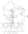
- FIG. 1 A preferred embodiment of the winder (1) according to the invention for winding and changing the winding of film webs, especially tubular films, is shown.
- the winder (1) has a machine housing (2).
- a first central drive (3) and a second central drive (4) are arranged on guides (5) in an area of the winder (1) on both sides of the outside of the machine housing (2).
- a driven winding shaft guide (6) is arranged at the same height on the inside of the machine housing (2). This works together with the central drives (3) or (4) and moves them back and forth on the horizontal guides (5).
- the central drives (3) and (4) take up winding shafts.
- a reel dispenser (14) is arranged, while on the other side of the guides (5) in which Figure 1 left, a vertical shaft transport unit (8) and a contact roller unit (9) is arranged.
- a support (13) for the winding shafts is arranged above and parallel to the guides (5).
- a horizontal winding shaft transport unit (7) is arranged below this unit, which receives new winding shafts and transports them below the winding shaft guide (6) in the direction of a second vertical winding shaft transport unit (8), which transports them upwards in the direction of the winding position.
- the vertical winding shaft transport unit (8) can also take up new winding shafts from above and transport them downwards in the direction of the winding position if the windings are to be wound up in the opposite winding direction.
- a contact roller unit (9) is arranged in a second area of the machine housing (2) (in the Figure 1 left) at the level of the guides (5) . It interacts with the winding shaft (15) or the winding (17) that is being formed. For example, it is designed to be pneumatically movable here.
- a deflection roller (10) is in turn arranged behind it.
- a separating device (11, 12) is arranged on the winding plane. They have the function of lifting, lowering or separating the film web.
- the hydraulic roll dispenser (14) is arranged on the opposite side of the machine frame (2) receiving the contact roller unit (9) following the guides (5) (in the Figure 1 right).
- the winding shaft (15) is coupled to a first central drive (3) arranged on the outer wall of the machine housing (2), and to the driven winding shaft guide (6) arranged on the inside of the machine housing (2).
- This first central drive (3) winds up the film web (16) in the winding position (WP), which is guided into the winder (1) via the deflection roller (10).
- the contact roller unit (9) presses on the winding shaft (15) or on the winding (17). With increasing diameter, the winding (17) with the winding shaft guide (6) and the first central drive (3) moves in the direction of the roll dispensing device (14).
- the winding shaft rests on a support (13) arranged on both sides of the machine housing (2).
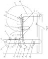
- the winding change is now first for right winding Figure 2 described.
- a new winding shaft (18) is inserted into the horizontal winding shaft transport unit (7) arranged below and transported in the direction of the vertical winding shaft transport unit (8), transferred to it and moved up to a parking position 1 (PP1).
- the first central drive (3) and the winding shaft guide (6) move the finished winding (17) in the direction of the storage arms (19) of the roll output device (14).
- the second central drive (4) is in its park position (PP) (not shown here).
- the contact roller unit (9) is horizontally away from the winding (17) (in the Figure 2 to the left), moved out of its winding position.
- the new winding shaft (18) is moved from parking position 1 (PP1) further up to parking position 2 (PP2).
- the first central drive (3) of the finished winding (17) decouples from the winding shaft guide (6) and is coupled to the outside of the machine housing wall (2) in its park position PP and continues to turn the wrap (17). Some of these steps run simultaneously.
- the second central drive (4) decouples from its parking position (PP) on the machine housing wall (2) and couples with the winding shaft guide (6) and is moved in the direction of the contact roller unit into a winding start position (cf. Figure 1 ).
- the lower separating device (12) is pivoted into the film web (16) and lifts it so that the new winding shaft (18) can move from the parking position 2 (PP2) to the winding start position.
- the winding shaft guide (6) moves with the second central drive (4) into the winding start position in which the new winding shaft (18) is located and the second central drive (4) couples to the winding shaft (18) and drives the winding shaft (18).
- the hook (20) of the vertical winding shaft transport unit moves down.
- the winding shaft guide with the second central drive and the winding shaft move into the winding position (WP).
- the lower separator (12) swivels into the cutting position.
- the contact roller unit (9) moves to the new winding shaft (18).
- the film web (16) is separated and the lower separating device (12) swings back.
- the new wrap is formed.
- the wrap change is now on for left winding Figure 3 described. It is assumed that the winding (17) in the winder (1) is being wound up with the first central drive (3).
- the new winding shaft (18) is inserted from above into the vertical winding shaft transport unit (8) and moved into a parking position 1 (PP1) above the winding level.
- the first central drive (3) and the winding shaft guide (6) move the finished winding (17) in front of the placement arms (19) of the roll output device (14).
- the second central drive (4) is in its park position PP. Now the contact roller unit (9) from the winding (17) away (in the Figure 1 to the left), moved out of its winding position.
- the new winding shaft (18) is moved from parking position 1 (PP1) in the direction of the winding plane to parking position 2 (PP2).
- the first central drive (3) of the full winding (17) decouples from the winding shaft guide (6) and couples to the outside Machine housing wall (2) in its parking position (PP). Some of these steps run simultaneously.
- the second opposite central drive (4) decouples from its parking position (PP) in the machine housing wall (2) and couples with the winding shaft guide (6) and both move in the direction of the contact roller unit (9), into the winding start position (cf. Figure 3 ).
- the upper separating device (11) is pivoted into the film web (16) and presses the film web (16) down so that the new winding shaft (18) can move from the parking position 2 (PP2) to the winding start position.
- the winding shaft guide (6) moves with the second central drive (4) into the winding start position in which the new winding shaft (18) is located and the second central drive (4) couples to the winding shaft (18) and drives the winding shaft (18).
- the hook (20) of the vertical winding shaft transport unit (8) moves down.
- the winding shaft guide, the second central drive and the new winding shaft move into the winding position (WP).
- the upper separator (11) swings back.
- the lower separating device (12) swivels upwards into the cutting position.
- the contact roller unit (9) moves to the new winding shaft (18).
- the film web (16) is separated and the lower separating device (12) swings back.
- the new wrap is formed.
- the finished reel (17) can now be released from the winder (1) via the reel dispenser (14).
Landscapes
- Replacement Of Web Rolls (AREA)
- Winding Of Webs (AREA)
Priority Applications (1)
| Application Number | Priority Date | Filing Date | Title |
|---|---|---|---|
| PL19000556T PL3666700T3 (pl) | 2018-12-11 | 2019-12-11 | Urządzenie do nawijania i wymiany zwojów materiału wstęgowego i sposób do tego |
Applications Claiming Priority (1)
| Application Number | Priority Date | Filing Date | Title |
|---|---|---|---|
| DE102018009632.8A DE102018009632B4 (de) | 2018-12-11 | 2018-12-11 | Vorrichtung zum Aufwickeln und Wickelwechsel von bahnförmigem Material und ein Verfahren dafür |
Publications (2)
| Publication Number | Publication Date |
|---|---|
| EP3666700A1 true EP3666700A1 (fr) | 2020-06-17 |
| EP3666700B1 EP3666700B1 (fr) | 2021-09-08 |
Family
ID=68916163
Family Applications (1)
| Application Number | Title | Priority Date | Filing Date |
|---|---|---|---|
| EP19000556.1A Active EP3666700B1 (fr) | 2018-12-11 | 2019-12-11 | Dispositif d'enroulement et de changement de bobine de matériau en forme de bande et procédé correspondant |
Country Status (11)
| Country | Link |
|---|---|
| US (1) | US11339021B2 (fr) |
| EP (1) | EP3666700B1 (fr) |
| JP (1) | JP6918085B2 (fr) |
| KR (1) | KR102314304B1 (fr) |
| CN (1) | CN111302117B (fr) |
| CA (1) | CA3064404C (fr) |
| DE (1) | DE102018009632B4 (fr) |
| ES (1) | ES2893577T3 (fr) |
| PL (1) | PL3666700T3 (fr) |
| RU (1) | RU2737008C1 (fr) |
| TW (1) | TWI782243B (fr) |
Cited By (3)
| Publication number | Priority date | Publication date | Assignee | Title |
|---|---|---|---|---|
| US11654605B2 (en) | 2018-10-13 | 2023-05-23 | Hosokawa Alpine Aktiengesellschaft | Die head and process to manufacture multilayer tubular film |
| US12330364B2 (en) | 2020-01-21 | 2025-06-17 | Hosokawa Alpine Aktiengesellschaft | Device and process to permit monoaxial changes in the length of film webs |
| US12343920B2 (en) | 2022-01-29 | 2025-07-01 | Hosokawa Alpine Aktiengesellschaft | Process and equipment to regulate the thickness of oriented tubular film that is manufactured in a film blowing process |
Families Citing this family (4)
| Publication number | Priority date | Publication date | Assignee | Title |
|---|---|---|---|---|
| DE102018009632B4 (de) | 2018-12-11 | 2021-12-09 | Hosokawa Alpine Aktiengesellschaft | Vorrichtung zum Aufwickeln und Wickelwechsel von bahnförmigem Material und ein Verfahren dafür |
| CN112976528B (zh) * | 2021-02-06 | 2022-08-30 | 广东新佳兴包装材料有限公司 | 一种双面防雾型bopp膜制备装置 |
| DE102022004478A1 (de) | 2022-11-30 | 2024-06-06 | Hosokawa Alpine Aktiengesellschaft | Vorrichtung zum Aufwickeln und Wickelwechsel von bahnförmigem Material und Verfahren dafür |
| US20240317525A1 (en) * | 2023-03-24 | 2024-09-26 | New Era Converting Machinery, Inc. | Dual position automatic winder |
Citations (4)
| Publication number | Priority date | Publication date | Assignee | Title |
|---|---|---|---|---|
| DE4428249A1 (de) | 1993-08-18 | 1995-02-23 | Chemiefaser Lenzing Ag | Wickelmaschine |
| DE19755357A1 (de) * | 1997-12-12 | 1999-06-24 | Freudenberg Carl Fa | Portal-Tragwalzenwickler zur stillstandsfreien Aufwicklung bahnförmiger Materialien |
| DE10035894A1 (de) * | 1999-09-16 | 2001-04-05 | Fuji Iron Works | Wickeleinrichtung für Bandmaterial |
| EP2261152A1 (fr) * | 2008-04-11 | 2010-12-15 | Fuji Tekko Co., Ltd | Enrouleur |
Family Cites Families (99)
| Publication number | Priority date | Publication date | Assignee | Title |
|---|---|---|---|---|
| DE291871C (fr) | ||||
| US2206981A (en) | 1938-07-13 | 1940-07-09 | Sturtevant Mill Co | Air separator |
| AT304058B (de) | 1966-04-22 | 1972-12-27 | Exxon Research Engineering Co | Verfahren und Vorrichtung zur Herstellung von transparenten Schlauchfolien |
| NO126423B (fr) | 1970-10-09 | 1973-02-05 | Thordarson Jon | |
| DE2132098A1 (de) | 1971-06-28 | 1973-01-18 | Windmoeller & Hoelscher | Kuehlvorrichtung fuer mittels eines folienblaskopfes hergestellte kunststoff-schlauchfolien |
| US3770124A (en) | 1971-12-21 | 1973-11-06 | Combustion Eng | Swing back whizzer blades for mechanical air separator |
| US3809515A (en) | 1972-03-03 | 1974-05-07 | Farrell Patent Co | Extrusion die for blowing plastic film |
| DE2250151B2 (de) | 1972-10-13 | 1975-07-31 | Barmag Barmer Maschinenfabrik Ag, 5600 Wuppertal | StrangpreBkopf zum Herstellen einer mehrschichtigen Schlauchfolie |
| US3962023A (en) | 1974-07-17 | 1976-06-08 | Mackenzie Trading Co. Ltd. | Apparatus for applying handles to plastic bags |
| DE2555848A1 (de) | 1975-12-11 | 1977-06-23 | Windmoeller & Hoelscher | Kuehlvorrichtung fuer mittels eines folienblaskopfes hergestellte kunststoff-schlauchfolien mit luftkuehlung |
| USRE33085E (en) | 1976-01-12 | 1989-10-10 | Precleaner | |
| US4018388A (en) | 1976-05-13 | 1977-04-19 | Andrews Norwood H | Jet-type axial pulverizer |
| DE2641620C3 (de) | 1976-09-16 | 1987-07-09 | Krupp Polysius Ag, 4720 Beckum | Rollenmühle mit Sichter |
| US4165356A (en) | 1978-05-15 | 1979-08-21 | Owens-Illinois, Inc. | Method of forming tubular plastic material having a flare-top edge using a blow head |
| DE3140294C2 (de) | 1981-10-10 | 1983-11-17 | Alpine Ag, 8900 Augsburg | Verfahren und Vorrichtung zum Trennen eines Gutgemisches in Komponenten unterschiedlicher Mahlbarkeit |
| DE3338138C2 (de) | 1983-10-20 | 1986-01-16 | Alpine Ag, 8900 Augsburg | Fließbett-Gegenstrahlmühle |
| JPS60141229U (ja) | 1984-02-28 | 1985-09-19 | 酒井美化工業株式会社 | 発泡シ−ト |
| DE3425101A1 (de) | 1984-07-07 | 1986-01-16 | Heinz 4630 Bochum Jäger | Verfahren und sichter zur trennscharfen sichtung eines gutstromes, insbesondere von zement |
| CN1004339B (zh) * | 1985-06-29 | 1989-05-31 | 阿莱德公司 | 运动细丝钳位和切割联合系统 |
| CN1005498B (zh) | 1985-07-02 | 1989-10-18 | 湖南大学 | 锻件瞬时温度测定装置 |
| SU1615113A1 (ru) * | 1989-01-12 | 1990-12-23 | Предприятие П/Я М-5064 | Устройство дл намотки ленточного материала |
| JP2674185B2 (ja) | 1989-02-28 | 1997-11-12 | 三菱樹脂株式会社 | 多層環状口金 |
| FR2658096B1 (fr) | 1990-02-13 | 1992-06-05 | Fives Cail Babcock | Selecteur a air a action centrifuge. |
| WO1991018813A1 (fr) * | 1990-06-08 | 1991-12-12 | Beloit Corporation | Dispositif de bobinage pour machines a decouper a roulettes du type a cylindre d'appui ou similaire |
| JPH074557B2 (ja) | 1990-10-23 | 1995-01-25 | 株式会社栗本鐵工所 | 粉砕媒体を使用した気流粉砕方法 |
| DE4100338A1 (de) | 1991-01-08 | 1992-07-09 | Nied Roland | Verfahren zum ermitteln des grades der befuellung eines behaelters |
| DE4109369A1 (de) | 1991-03-22 | 1992-09-24 | Reifenhaeuser Masch | Werkzeugkopf zum strangpressen von schlauchfoermigen oder rohrfoermigen vorformlingen aus thermoplastifiziertem kunststoff |
| DE4116964C2 (de) * | 1991-05-24 | 1994-03-31 | Hans Heuser Maschinen Und Mess | Rollenschneid- und Wickelmaschine |
| DE4140656C1 (fr) | 1991-12-10 | 1992-09-10 | Alpine Ag, 8900 Augsburg, De | |
| JPH0615193U (ja) | 1992-07-29 | 1994-02-25 | ホーチキ株式会社 | Catv監視システム |
| DE9214651U1 (de) | 1992-10-28 | 1993-02-18 | Windmöller & Hölscher, 4540 Lengerich | Blasfolienextrusionskopf |
| NO176507C (no) | 1992-12-01 | 1995-04-19 | Sinvent Sintef Gruppen | Rotor for klassifiserings-apparat |
| US5370327A (en) * | 1993-05-06 | 1994-12-06 | Beloit Technologies, Inc. | Method and apparatus for reeling a wound web roll |
| DE4405462C1 (de) | 1994-02-21 | 1995-04-20 | Windmoeller & Hoelscher | Folienblaskopf zur Extrusion eines Schlauches aus thermoplastischer Kunststoffschmelze |
| RU2128617C1 (ru) | 1994-06-16 | 1999-04-10 | Фабио Перини С.П.А. | Перемоточный станок для образования рулона ленточного материала |
| US5544841A (en) * | 1994-08-18 | 1996-08-13 | Beloit Technologies, Inc. | Method and apparatus for reeling a traveling web into a wound web roll |
| DE19507799C2 (de) * | 1995-03-06 | 1997-04-30 | Kleinewefers Ramisch Gmbh | Vorrichtung zum kontinuierlichen Aufwickeln von bahnförmigem Wickelgut |
| DE29505311U1 (de) | 1995-03-29 | 1995-06-01 | Omya GmbH, 50968 Köln | Zentrifugalkraftsichter |
| CA2219022A1 (fr) | 1995-04-24 | 1996-10-31 | Black Clawson Sano Inc. | Matrice a extrusion |
| CA2191630A1 (fr) | 1995-12-14 | 1997-06-15 | Surendra M. Sagar | Filiere annulaire de co-extrusion |
| US5673870A (en) * | 1995-12-19 | 1997-10-07 | Beloit Technologies, Inc. | Method and apparatus for reeling a traveling paper web |
| DE19613902C2 (de) | 1996-04-06 | 1998-08-06 | Hosokawa Alpine Ag | Windsichter mit steifem Sichterradgrundkörper |
| WO1998017459A1 (fr) | 1996-10-22 | 1998-04-30 | Schirmer Henry G | Matrice de coextrusion a disques modulaires |
| ATE290504T1 (de) * | 1997-01-25 | 2005-03-15 | Voith Paper Patent Gmbh | Wickelmaschine und verfahren zum kontinuierlichen aufwickeln einer materialbahn |
| DE19728382C2 (de) | 1997-07-03 | 2003-03-13 | Hosokawa Alpine Ag & Co | Verfahren und Vorrichtung zur Fließbett-Strahlmahlung |
| RU2124465C1 (ru) * | 1997-11-26 | 1999-01-10 | Манулик Сергей Николаевич | Перемоточный станок для намотки в рулон ленточных материалов |
| ATE290041T1 (de) | 1997-12-19 | 2005-03-15 | Trexel Inc | Mikrozellulares schaumstoff- extrusions/blasformverfahren und damit hergestellter gegenstand |
| JP2000280726A (ja) | 1998-04-07 | 2000-10-10 | Nippon Soken Inc | 車両暖房装置 |
| FI110424B (fi) * | 1998-06-18 | 2003-01-31 | Metso Paper Inc | Rullain ja menetelmä rainan rullaamiseksi |
| DE19840344C2 (de) | 1998-09-04 | 2002-04-04 | Hosokawa Alpine Ag & Co | Sichtrad für einen Zentrifugalkraft-Windsichter |
| US6189821B1 (en) | 1999-03-25 | 2001-02-20 | Raymond James | Apparatus for plastic particle reduction using dove-tailed blade |
| US6398139B1 (en) | 1999-08-23 | 2002-06-04 | Roland Nied | Process for fluidized-bed jet milling, device for carrying out this process and unit with such a device for carrying out this process |
| DE10029175B4 (de) | 1999-09-09 | 2004-10-07 | Kdesign Gmbh | Verfahren und Vorrichtung zur Steuerung und Regelung des Dickenprofils bei der Blasfolienherstellung |
| DE20022174U1 (de) | 1999-09-09 | 2001-05-17 | Kdesign GmbH, 51371 Leverkusen | Vorrichtung zur Steuerung und Regelung des Dickenprofils bei der Blasfolienherstellung |
| DE10033628A1 (de) | 2000-07-11 | 2002-01-24 | Hosokawa Alpine Ag & Co | Fliessbett-Gegenstrahlmühle |
| DE10059306C1 (de) | 2000-11-29 | 2002-05-16 | Reifenhaeuser Masch | Werkzeugkopf zur Extrusion eines rohrförmigen Stranges aus mindestens einer thermoplastischen Kunststoffschmelze für die Herstellung von Blasfolien |
| DE20117248U1 (de) | 2001-10-24 | 2003-03-06 | Reinhold, Klaus, 49525 Lengerich | Vorrichtung zum Aufwickeln von Materialbahnen |
| US6877689B2 (en) * | 2002-09-27 | 2005-04-12 | C.G. Bretting Mfg. Co., Inc. | Rewinder apparatus and method |
| EP1433730B1 (fr) | 2002-10-25 | 2007-01-10 | Reifenhäuser GmbH & Co. Maschinenfabrik | Dispositif pour enrouler et méthode pour changer un mandarin d'enroulage dans une enrouleuse |
| US7028931B2 (en) | 2003-11-03 | 2006-04-18 | Riley Power, Inc. | Dynamic ring classifier for a coal pulverizer |
| US7255301B2 (en) * | 2004-03-01 | 2007-08-14 | Andritz Tissue Inc. | Reel spool storage and loading device and method |
| US7913851B2 (en) | 2004-04-19 | 2011-03-29 | Jin-Hong Chang | Separator for grinding mill |
| DE102004040151B4 (de) | 2004-08-19 | 2008-08-21 | Hosokawa Alpine Ag | Folienblaskopf für die Herstellung von Schlauchfolien |
| JP5048646B2 (ja) | 2006-02-24 | 2012-10-17 | 太平洋セメント株式会社 | 遠心式空気分級機 |
| KR20080113392A (ko) | 2006-03-01 | 2008-12-30 | 가부시키가이샤 가네카 | 다층 폴리이미드 필름의 제조 방법 |
| DE102006048850A1 (de) | 2006-10-16 | 2008-04-17 | Evonik Degussa Gmbh | Amorphe submicron Partikel |
| DE102006044833B4 (de) | 2006-09-20 | 2010-01-21 | Babcock Borsig Service Gmbh | Zentrifugalsichter und Verfahren zum Sichten |
| EP1947043B1 (fr) | 2007-01-18 | 2010-11-03 | Reifenhäuser GmbH & Co. KG Maschinenfabrik | Dispositif d'enroulement |
| FI121303B (fi) | 2008-07-03 | 2010-09-30 | Metso Paper Inc | Kuiturainan pituusleikkurijärjestely ja menetelmä kuiturainan pituusleikkaamiseksi |
| DE202008012076U1 (de) | 2008-09-11 | 2008-11-27 | ETEC Gesellschaft für technische Keramik mbH | Verschleißschutz-Flächenelement |
| US8876512B2 (en) | 2008-09-23 | 2014-11-04 | Cryovac, Inc. | Die for coextruding a plurality of fluid layers |
| US20100072655A1 (en) | 2008-09-23 | 2010-03-25 | Cryovac, Inc. | Die, system, and method for coextruding a plurality of fluid layers |
| CN201280352Y (zh) | 2008-09-28 | 2009-07-29 | 沙市轻工机械有限公司 | 高速自动接纸退纸机 |
| US8231007B2 (en) | 2009-01-29 | 2012-07-31 | Wark Rickey E | Static classifier cage |
| FR2941389B1 (fr) | 2009-01-29 | 2011-10-14 | Fives Fcb | Dispositif de separation granulometrique selective de matieres pulverulentes solides, a action centrifuge, et procede d'utilisation d'un tel dispositif |
| DE102009033171B4 (de) | 2009-07-13 | 2016-03-03 | Hosokawa Alpine Ag | Verfahren zur Regelung der Foliendicke von verstreckten Schlauchfolien sowie Vorrichtung zur Durchführung des Verfahrens |
| CN101987703B (zh) | 2009-07-30 | 2012-08-29 | 全利机械股份有限公司 | 薄纸卷绕机预卷纸张截断机构及其方法 |
| DE102009046593A1 (de) | 2009-11-10 | 2011-05-12 | Windmöller & Hölscher Kg | Vorrichtung und Verfahren zum Längsrecken einer Folienbahn |
| DE102009046585A1 (de) | 2009-11-10 | 2011-05-19 | Windmöller & Hölscher Kg | Vorrichtung und Verfahren zum Längsrecken einer Folienbahn |
| US20110229722A1 (en) | 2010-03-18 | 2011-09-22 | Cryovac, Inc. | Multilayer Oxygen Barrier Film Comprising a Plurality of Adjoining Microlayers Comprising Ethylene/Vinyl Alcohol Copolymer |
| JP5812668B2 (ja) | 2010-05-14 | 2015-11-17 | 三菱日立パワーシステムズ株式会社 | 回転式分級機 |
| DE102011085735A1 (de) | 2011-11-03 | 2013-05-08 | Windmöller & Hölscher Kg | Reckwerk und Verfahren zum Längen von Folienbahnen |
| US8870561B2 (en) | 2012-03-16 | 2014-10-28 | Bbs Corporation | Layer sequence repeater module for a modular disk co-extrusion die and products thereof |
| JP2013245105A (ja) * | 2012-05-29 | 2013-12-09 | Fuji Iron Works Co Ltd | シート巻取装置 |
| DE102013016898A1 (de) | 2013-10-13 | 2015-04-16 | Reifenhäuser GmbH & Co. KG Maschinenfabrik | Innenkühlkörper für eine Blasfolienanlage, Blasfolienanlage mit einem solchen Innenkörper sowie Verfahren zum Betreiben einer solchen Blasfolienanlage |
| EP2873508B1 (fr) | 2013-10-15 | 2019-09-11 | Reifenhäuser GmbH & Co. KG Maschinenfabrik | Tête d'extrusion |
| DE112015001615B4 (de) | 2014-04-03 | 2018-04-12 | Macro Technology Ltd. | Bauteilelement für eine Co-Extrusionsdüse mit rechteckigem Zufuhrkanal und Co-Extrusionsdüse |
| CN204183848U (zh) | 2014-10-17 | 2015-03-04 | 广东金明精机股份有限公司 | 多层共挤吹膜设备 |
| DE102014017556B4 (de) | 2014-11-28 | 2019-05-16 | Hosokawa Alpine Aktiengesellschaft | Innenkühlturm für Folienblasanlagen |
| TWM504084U (zh) * | 2015-01-29 | 2015-07-01 | Cosmo Machinery Co Ltd | 捲筒式膜料/袋料分裝捲取裝置 |
| CN205634333U (zh) * | 2016-05-19 | 2016-10-12 | 天津市禹神建筑防水材料有限公司 | 一种防水卷材的收卷切割系统 |
| EP3266586B1 (fr) | 2016-07-06 | 2021-09-22 | Reifenhäuser GmbH & Co. KG Maschinenfabrik | Outil multicouches |
| DE102016012388A1 (de) | 2016-10-18 | 2018-04-19 | Reifenhäuser GmbH & Co. KG Maschinenfabrik | Verteilerplattenpaket für einen blaskopf einer blasfolienanlage, blaskopf, verfahren zum herstellen einer folie im blasfolienverfahren, verfahren zum umrüsten eines blaskopfes sowie blasfolienanlage |
| DE102016015051B4 (de) | 2016-12-16 | 2019-01-31 | Hosokawa Alpine Aktiengesellschaft | Sichtrad für einen Zentrifugalkraft-Windsichter |
| EP3686700B1 (fr) | 2018-07-27 | 2020-12-16 | Eisenmann SE | Procédé de surveillance d'une installation d'automatisation |
| DE102018008127B4 (de) | 2018-10-13 | 2022-06-09 | Hosokawa Alpine Aktiengesellschaft | Blaskopf und Verfahren zur Herstellung einer Mehrschichtschlauchfolie |
| DE102018009632B4 (de) | 2018-12-11 | 2021-12-09 | Hosokawa Alpine Aktiengesellschaft | Vorrichtung zum Aufwickeln und Wickelwechsel von bahnförmigem Material und ein Verfahren dafür |
| DE102020000334A1 (de) | 2020-01-21 | 2021-07-22 | Hosokawa Alpine Aktiengesellschaft | Vorrichtung und Verfahren zur monaxialen Längenänderung von Folienbahnen |
| RU2737006C1 (ru) | 2020-06-09 | 2020-11-24 | Российская Федерация, от имени которой выступает Государственная корпорация по атомной энергии "Росатом" (Госкорпорация "Росатом") | Устройство для генерации электромагнитных возмущений в низкотемпературной магнитоактивной плазме |
-
2018
- 2018-12-11 DE DE102018009632.8A patent/DE102018009632B4/de active Active
-
2019
- 2019-12-06 TW TW108144774A patent/TWI782243B/zh active
- 2019-12-09 RU RU2019140284A patent/RU2737008C1/ru active
- 2019-12-10 KR KR1020190163363A patent/KR102314304B1/ko active Active
- 2019-12-10 JP JP2019222864A patent/JP6918085B2/ja active Active
- 2019-12-10 US US16/709,025 patent/US11339021B2/en active Active
- 2019-12-10 CA CA3064404A patent/CA3064404C/fr active Active
- 2019-12-11 EP EP19000556.1A patent/EP3666700B1/fr active Active
- 2019-12-11 ES ES19000556T patent/ES2893577T3/es active Active
- 2019-12-11 PL PL19000556T patent/PL3666700T3/pl unknown
- 2019-12-11 CN CN201911262431.4A patent/CN111302117B/zh active Active
Patent Citations (4)
| Publication number | Priority date | Publication date | Assignee | Title |
|---|---|---|---|---|
| DE4428249A1 (de) | 1993-08-18 | 1995-02-23 | Chemiefaser Lenzing Ag | Wickelmaschine |
| DE19755357A1 (de) * | 1997-12-12 | 1999-06-24 | Freudenberg Carl Fa | Portal-Tragwalzenwickler zur stillstandsfreien Aufwicklung bahnförmiger Materialien |
| DE10035894A1 (de) * | 1999-09-16 | 2001-04-05 | Fuji Iron Works | Wickeleinrichtung für Bandmaterial |
| EP2261152A1 (fr) * | 2008-04-11 | 2010-12-15 | Fuji Tekko Co., Ltd | Enrouleur |
Cited By (3)
| Publication number | Priority date | Publication date | Assignee | Title |
|---|---|---|---|---|
| US11654605B2 (en) | 2018-10-13 | 2023-05-23 | Hosokawa Alpine Aktiengesellschaft | Die head and process to manufacture multilayer tubular film |
| US12330364B2 (en) | 2020-01-21 | 2025-06-17 | Hosokawa Alpine Aktiengesellschaft | Device and process to permit monoaxial changes in the length of film webs |
| US12343920B2 (en) | 2022-01-29 | 2025-07-01 | Hosokawa Alpine Aktiengesellschaft | Process and equipment to regulate the thickness of oriented tubular film that is manufactured in a film blowing process |
Also Published As
| Publication number | Publication date |
|---|---|
| CN111302117B (zh) | 2022-07-01 |
| CA3064404A1 (fr) | 2020-06-11 |
| JP2020097489A (ja) | 2020-06-25 |
| RU2737008C1 (ru) | 2020-11-24 |
| DE102018009632B4 (de) | 2021-12-09 |
| US20200180890A1 (en) | 2020-06-11 |
| ES2893577T3 (es) | 2022-02-09 |
| EP3666700B1 (fr) | 2021-09-08 |
| JP6918085B2 (ja) | 2021-08-11 |
| PL3666700T3 (pl) | 2022-01-24 |
| DE102018009632A1 (de) | 2020-06-18 |
| TWI782243B (zh) | 2022-11-01 |
| KR102314304B1 (ko) | 2021-10-20 |
| KR20200071679A (ko) | 2020-06-19 |
| TW202028097A (zh) | 2020-08-01 |
| US11339021B2 (en) | 2022-05-24 |
| CN111302117A (zh) | 2020-06-19 |
| CA3064404C (fr) | 2022-04-05 |
| BR102019026088A2 (pt) | 2020-07-07 |
Similar Documents
| Publication | Publication Date | Title |
|---|---|---|
| EP3666700A1 (fr) | Dispositif d'enroulement et de changement de bobine de matériau en forme de bande et procédé correspondant | |
| EP2873499B1 (fr) | Dispositif de coupe pour couper une bande fine et collante, notamment une bande de corde | |
| EP3038962B1 (fr) | Dispositif de dévidage automatique de matériaux en bande continue et procédé de fonctionnement d'un tel dispositif | |
| EP2061702A1 (fr) | Installation d'étiquetage | |
| EP0462157B1 (fr) | Dispositif pour relier des bandes de materiau | |
| DE202014101081U1 (de) | Aufwickeleinrichtung zum Aufwickeln einer gummierten Cordbahn mit parallel geführter Zwischenlagenbahn auf eine Materialspule | |
| DE102022105161A1 (de) | Materialstreifen-Verarbeitungssystem | |
| DE202013103530U1 (de) | Abwickelvorrichtung zum Abwickeln von zu einer Rolle aufgerolltem Cordband, insbesondere Stahl- oder Textilcord, zur Herstellung eines Reifens | |
| DE2902480A1 (de) | Vorrichtung fuer das austauschen sich drehender wickeldorne, auf denen ein band aufgewickelt ist | |
| DE102018102914A1 (de) | Vorrichtung und Verfahren zur Zuführung von Draht in eine Produktionsanlage für Maschinenelemente elektrischer Maschinen | |
| EP2803609B1 (fr) | Machine d'enroulement de matériaux en forme de bande | |
| EP2079654A1 (fr) | Rouleau presseur pivotant dans une bobineuse à retournement | |
| EP3237315B1 (fr) | Dispositif de prélèvement de rouleaux, dispositif d'enroulement et procédé d'évacuation de plusieurs rouleaux complètement enroulés | |
| DE202014103124U1 (de) | Slitter zum Schneiden eines Cordbandes | |
| WO2025157823A1 (fr) | Dispositif de pressage et de séparation d'une bande de matériau pour un enrouleur réversible | |
| EP4438536A1 (fr) | Dispositif et procédé pour relier deux bandes de matériau à longueur finie se déroulant chacun d'un bobines en métal à une bande de matériau sans fin pouvant être utilisée dans une production sans interruption | |
| DE102022004478A1 (de) | Vorrichtung zum Aufwickeln und Wickelwechsel von bahnförmigem Material und Verfahren dafür | |
| DE102017105298B4 (de) | Konfektionierungsanlage | |
| EP2601120B1 (fr) | Dispositif pour l'enroulement de matériaux en forme de bande à rouler | |
| EP3697709B1 (fr) | Poste de dévidage | |
| DE102014109516A1 (de) | Slitter zum Schneiden eines Cordbandes | |
| DE60015144T2 (de) | Verfahren zum kontinuierlichen aufwickeln von papier und wickler | |
| EP2301871B1 (fr) | Procédé et dispositif de chargement de noyaux pour enrouleuse avec deux cylindres de support en fonctionnement continu | |
| DE10218137A1 (de) | Einrichtung zum Zuführen von aufgewickeltem Verpackungsmaterial | |
| WO2020224820A1 (fr) | Poste de déroulement |
Legal Events
| Date | Code | Title | Description |
|---|---|---|---|
| PUAI | Public reference made under article 153(3) epc to a published international application that has entered the european phase |
Free format text: ORIGINAL CODE: 0009012 |
|
| STAA | Information on the status of an ep patent application or granted ep patent |
Free format text: STATUS: THE APPLICATION HAS BEEN PUBLISHED |
|
| AK | Designated contracting states |
Kind code of ref document: A1 Designated state(s): AL AT BE BG CH CY CZ DE DK EE ES FI FR GB GR HR HU IE IS IT LI LT LU LV MC MK MT NL NO PL PT RO RS SE SI SK SM TR |
|
| AX | Request for extension of the european patent |
Extension state: BA ME |
|
| RIN1 | Information on inventor provided before grant (corrected) |
Inventor name: GOELLNER MANFRED Inventor name: KAMMER, JENS CHRISTIAN Inventor name: HOYER, NICOLE Inventor name: KLIMEK, LOTHAR Inventor name: DURNER, KLAUS Inventor name: WESTPHAL, SEBASTIAN |
|
| STAA | Information on the status of an ep patent application or granted ep patent |
Free format text: STATUS: REQUEST FOR EXAMINATION WAS MADE |
|
| 17P | Request for examination filed |
Effective date: 20201217 |
|
| RBV | Designated contracting states (corrected) |
Designated state(s): AL AT BE BG CH CY CZ DE DK EE ES FI FR GB GR HR HU IE IS IT LI LT LU LV MC MK MT NL NO PL PT RO RS SE SI SK SM TR |
|
| RIN1 | Information on inventor provided before grant (corrected) |
Inventor name: HOYER, NICOLE Inventor name: KAMMER, JENS CHRISTIAN Inventor name: DURNER, KLAUS Inventor name: WESTPHAL, SEBASTIAN Inventor name: KLIMEK, LOTHAR Inventor name: GOELLNER MANFRED |
|
| GRAP | Despatch of communication of intention to grant a patent |
Free format text: ORIGINAL CODE: EPIDOSNIGR1 |
|
| STAA | Information on the status of an ep patent application or granted ep patent |
Free format text: STATUS: GRANT OF PATENT IS INTENDED |
|
| GRAS | Grant fee paid |
Free format text: ORIGINAL CODE: EPIDOSNIGR3 |
|
| GRAA | (expected) grant |
Free format text: ORIGINAL CODE: 0009210 |
|
| STAA | Information on the status of an ep patent application or granted ep patent |
Free format text: STATUS: THE PATENT HAS BEEN GRANTED |
|
| INTG | Intention to grant announced |
Effective date: 20210723 |
|
| AK | Designated contracting states |
Kind code of ref document: B1 Designated state(s): AL AT BE BG CH CY CZ DE DK EE ES FI FR GB GR HR HU IE IS IT LI LT LU LV MC MK MT NL NO PL PT RO RS SE SI SK SM TR |
|
| REG | Reference to a national code |
Ref country code: GB Ref legal event code: FG4D Free format text: NOT ENGLISH |
|
| REG | Reference to a national code |
Ref country code: CH Ref legal event code: EP Ref country code: AT Ref legal event code: REF Ref document number: 1428422 Country of ref document: AT Kind code of ref document: T Effective date: 20210915 |
|
| REG | Reference to a national code |
Ref country code: IE Ref legal event code: FG4D Free format text: LANGUAGE OF EP DOCUMENT: GERMAN |
|
| REG | Reference to a national code |
Ref country code: DE Ref legal event code: R096 Ref document number: 502019002210 Country of ref document: DE |
|
| REG | Reference to a national code |
Ref country code: LT Ref legal event code: MG9D |
|
| REG | Reference to a national code |
Ref country code: NL Ref legal event code: MP Effective date: 20210908 |
|
| PG25 | Lapsed in a contracting state [announced via postgrant information from national office to epo] |
Ref country code: SE Free format text: LAPSE BECAUSE OF FAILURE TO SUBMIT A TRANSLATION OF THE DESCRIPTION OR TO PAY THE FEE WITHIN THE PRESCRIBED TIME-LIMIT Effective date: 20210908 Ref country code: RS Free format text: LAPSE BECAUSE OF FAILURE TO SUBMIT A TRANSLATION OF THE DESCRIPTION OR TO PAY THE FEE WITHIN THE PRESCRIBED TIME-LIMIT Effective date: 20210908 Ref country code: FI Free format text: LAPSE BECAUSE OF FAILURE TO SUBMIT A TRANSLATION OF THE DESCRIPTION OR TO PAY THE FEE WITHIN THE PRESCRIBED TIME-LIMIT Effective date: 20210908 Ref country code: HR Free format text: LAPSE BECAUSE OF FAILURE TO SUBMIT A TRANSLATION OF THE DESCRIPTION OR TO PAY THE FEE WITHIN THE PRESCRIBED TIME-LIMIT Effective date: 20210908 Ref country code: NO Free format text: LAPSE BECAUSE OF FAILURE TO SUBMIT A TRANSLATION OF THE DESCRIPTION OR TO PAY THE FEE WITHIN THE PRESCRIBED TIME-LIMIT Effective date: 20211208 Ref country code: BG Free format text: LAPSE BECAUSE OF FAILURE TO SUBMIT A TRANSLATION OF THE DESCRIPTION OR TO PAY THE FEE WITHIN THE PRESCRIBED TIME-LIMIT Effective date: 20211208 Ref country code: LT Free format text: LAPSE BECAUSE OF FAILURE TO SUBMIT A TRANSLATION OF THE DESCRIPTION OR TO PAY THE FEE WITHIN THE PRESCRIBED TIME-LIMIT Effective date: 20210908 |
|
| REG | Reference to a national code |
Ref country code: ES Ref legal event code: FG2A Ref document number: 2893577 Country of ref document: ES Kind code of ref document: T3 Effective date: 20220209 |
|
| PG25 | Lapsed in a contracting state [announced via postgrant information from national office to epo] |
Ref country code: LV Free format text: LAPSE BECAUSE OF FAILURE TO SUBMIT A TRANSLATION OF THE DESCRIPTION OR TO PAY THE FEE WITHIN THE PRESCRIBED TIME-LIMIT Effective date: 20210908 Ref country code: GR Free format text: LAPSE BECAUSE OF FAILURE TO SUBMIT A TRANSLATION OF THE DESCRIPTION OR TO PAY THE FEE WITHIN THE PRESCRIBED TIME-LIMIT Effective date: 20211209 |
|
| PG25 | Lapsed in a contracting state [announced via postgrant information from national office to epo] |
Ref country code: IS Free format text: LAPSE BECAUSE OF FAILURE TO SUBMIT A TRANSLATION OF THE DESCRIPTION OR TO PAY THE FEE WITHIN THE PRESCRIBED TIME-LIMIT Effective date: 20220108 Ref country code: SM Free format text: LAPSE BECAUSE OF FAILURE TO SUBMIT A TRANSLATION OF THE DESCRIPTION OR TO PAY THE FEE WITHIN THE PRESCRIBED TIME-LIMIT Effective date: 20210908 Ref country code: SK Free format text: LAPSE BECAUSE OF FAILURE TO SUBMIT A TRANSLATION OF THE DESCRIPTION OR TO PAY THE FEE WITHIN THE PRESCRIBED TIME-LIMIT Effective date: 20210908 Ref country code: RO Free format text: LAPSE BECAUSE OF FAILURE TO SUBMIT A TRANSLATION OF THE DESCRIPTION OR TO PAY THE FEE WITHIN THE PRESCRIBED TIME-LIMIT Effective date: 20210908 Ref country code: PT Free format text: LAPSE BECAUSE OF FAILURE TO SUBMIT A TRANSLATION OF THE DESCRIPTION OR TO PAY THE FEE WITHIN THE PRESCRIBED TIME-LIMIT Effective date: 20220110 Ref country code: NL Free format text: LAPSE BECAUSE OF FAILURE TO SUBMIT A TRANSLATION OF THE DESCRIPTION OR TO PAY THE FEE WITHIN THE PRESCRIBED TIME-LIMIT Effective date: 20210908 Ref country code: EE Free format text: LAPSE BECAUSE OF FAILURE TO SUBMIT A TRANSLATION OF THE DESCRIPTION OR TO PAY THE FEE WITHIN THE PRESCRIBED TIME-LIMIT Effective date: 20210908 Ref country code: AL Free format text: LAPSE BECAUSE OF FAILURE TO SUBMIT A TRANSLATION OF THE DESCRIPTION OR TO PAY THE FEE WITHIN THE PRESCRIBED TIME-LIMIT Effective date: 20210908 |
|
| REG | Reference to a national code |
Ref country code: DE Ref legal event code: R097 Ref document number: 502019002210 Country of ref document: DE |
|
| PLBE | No opposition filed within time limit |
Free format text: ORIGINAL CODE: 0009261 |
|
| STAA | Information on the status of an ep patent application or granted ep patent |
Free format text: STATUS: NO OPPOSITION FILED WITHIN TIME LIMIT |
|
| PG25 | Lapsed in a contracting state [announced via postgrant information from national office to epo] |
Ref country code: MC Free format text: LAPSE BECAUSE OF FAILURE TO SUBMIT A TRANSLATION OF THE DESCRIPTION OR TO PAY THE FEE WITHIN THE PRESCRIBED TIME-LIMIT Effective date: 20210908 Ref country code: DK Free format text: LAPSE BECAUSE OF FAILURE TO SUBMIT A TRANSLATION OF THE DESCRIPTION OR TO PAY THE FEE WITHIN THE PRESCRIBED TIME-LIMIT Effective date: 20210908 |
|
| 26N | No opposition filed |
Effective date: 20220609 |
|
| PG25 | Lapsed in a contracting state [announced via postgrant information from national office to epo] |
Ref country code: SI Free format text: LAPSE BECAUSE OF FAILURE TO SUBMIT A TRANSLATION OF THE DESCRIPTION OR TO PAY THE FEE WITHIN THE PRESCRIBED TIME-LIMIT Effective date: 20210908 |
|
| PG25 | Lapsed in a contracting state [announced via postgrant information from national office to epo] |
Ref country code: LU Free format text: LAPSE BECAUSE OF NON-PAYMENT OF DUE FEES Effective date: 20211211 Ref country code: IE Free format text: LAPSE BECAUSE OF NON-PAYMENT OF DUE FEES Effective date: 20211211 |
|
| P01 | Opt-out of the competence of the unified patent court (upc) registered |
Effective date: 20230515 |
|
| PG25 | Lapsed in a contracting state [announced via postgrant information from national office to epo] |
Ref country code: CY Free format text: LAPSE BECAUSE OF FAILURE TO SUBMIT A TRANSLATION OF THE DESCRIPTION OR TO PAY THE FEE WITHIN THE PRESCRIBED TIME-LIMIT Effective date: 20210908 |
|
| PG25 | Lapsed in a contracting state [announced via postgrant information from national office to epo] |
Ref country code: HU Free format text: LAPSE BECAUSE OF FAILURE TO SUBMIT A TRANSLATION OF THE DESCRIPTION OR TO PAY THE FEE WITHIN THE PRESCRIBED TIME-LIMIT; INVALID AB INITIO Effective date: 20191211 |
|
| PG25 | Lapsed in a contracting state [announced via postgrant information from national office to epo] |
Ref country code: MK Free format text: LAPSE BECAUSE OF FAILURE TO SUBMIT A TRANSLATION OF THE DESCRIPTION OR TO PAY THE FEE WITHIN THE PRESCRIBED TIME-LIMIT Effective date: 20210908 |
|
| PG25 | Lapsed in a contracting state [announced via postgrant information from national office to epo] |
Ref country code: MT Free format text: LAPSE BECAUSE OF FAILURE TO SUBMIT A TRANSLATION OF THE DESCRIPTION OR TO PAY THE FEE WITHIN THE PRESCRIBED TIME-LIMIT Effective date: 20210908 |
|
| PGFP | Annual fee paid to national office [announced via postgrant information from national office to epo] |
Ref country code: FR Payment date: 20250930 Year of fee payment: 7 |
|
| REG | Reference to a national code |
Ref country code: CH Ref legal event code: U11 Free format text: ST27 STATUS EVENT CODE: U-0-0-U10-U11 (AS PROVIDED BY THE NATIONAL OFFICE) Effective date: 20260101 |
|
| PGFP | Annual fee paid to national office [announced via postgrant information from national office to epo] |
Ref country code: DE Payment date: 20251217 Year of fee payment: 7 |
|
| PGFP | Annual fee paid to national office [announced via postgrant information from national office to epo] |
Ref country code: GB Payment date: 20251001 Year of fee payment: 7 |
|
| PGFP | Annual fee paid to national office [announced via postgrant information from national office to epo] |
Ref country code: AT Payment date: 20251126 Year of fee payment: 7 |
|
| PGFP | Annual fee paid to national office [announced via postgrant information from national office to epo] |
Ref country code: IT Payment date: 20251121 Year of fee payment: 7 |
|
| PGFP | Annual fee paid to national office [announced via postgrant information from national office to epo] |
Ref country code: TR Payment date: 20251204 Year of fee payment: 7 Ref country code: BE Payment date: 20251003 Year of fee payment: 7 |
|
| PGFP | Annual fee paid to national office [announced via postgrant information from national office to epo] |
Ref country code: CZ Payment date: 20251124 Year of fee payment: 7 |
|
| PGFP | Annual fee paid to national office [announced via postgrant information from national office to epo] |
Ref country code: PL Payment date: 20251013 Year of fee payment: 7 |
|
| PGFP | Annual fee paid to national office [announced via postgrant information from national office to epo] |
Ref country code: ES Payment date: 20260119 Year of fee payment: 7 |
|
| PGFP | Annual fee paid to national office [announced via postgrant information from national office to epo] |
Ref country code: CH Payment date: 20260101 Year of fee payment: 7 |