EP3677537B1 - Hebe- und transportvorrichtung - Google Patents
Hebe- und transportvorrichtung Download PDFInfo
- Publication number
- EP3677537B1 EP3677537B1 EP19219441.3A EP19219441A EP3677537B1 EP 3677537 B1 EP3677537 B1 EP 3677537B1 EP 19219441 A EP19219441 A EP 19219441A EP 3677537 B1 EP3677537 B1 EP 3677537B1
- Authority
- EP
- European Patent Office
- Prior art keywords
- lifting
- flange
- frame
- transporting device
- transport direction
- Prior art date
- Legal status (The legal status is an assumption and is not a legal conclusion. Google has not performed a legal analysis and makes no representation as to the accuracy of the status listed.)
- Active
Links
Images

Classifications
-
- B—PERFORMING OPERATIONS; TRANSPORTING
- B23—MACHINE TOOLS; METAL-WORKING NOT OTHERWISE PROVIDED FOR
- B23P—METAL-WORKING NOT OTHERWISE PROVIDED FOR; COMBINED OPERATIONS; UNIVERSAL MACHINE TOOLS
- B23P19/00—Machines for simply fitting together or separating metal parts or objects, or metal and non-metal parts, whether or not involving some deformation; Tools or devices therefor so far as not provided for in other classes
- B23P19/04—Machines for simply fitting together or separating metal parts or objects, or metal and non-metal parts, whether or not involving some deformation; Tools or devices therefor so far as not provided for in other classes for assembling or disassembling parts
- B23P19/06—Screw or nut setting or loosening machines
- B23P19/067—Bolt tensioners
-
- B—PERFORMING OPERATIONS; TRANSPORTING
- B66—HOISTING; LIFTING; HAULING
- B66F—HOISTING, LIFTING, HAULING OR PUSHING, NOT OTHERWISE PROVIDED FOR, e.g. DEVICES WHICH APPLY A LIFTING OR PUSHING FORCE DIRECTLY TO THE SURFACE OF A LOAD
- B66F3/00—Devices, e.g. jacks, adapted for uninterrupted lifting of loads
- B66F3/24—Devices, e.g. jacks, adapted for uninterrupted lifting of loads fluid-pressure operated
- B66F3/25—Constructional features
- B66F3/36—Load-engaging elements
-
- B—PERFORMING OPERATIONS; TRANSPORTING
- B25—HAND TOOLS; PORTABLE POWER-DRIVEN TOOLS; MANIPULATORS
- B25B—TOOLS OR BENCH DEVICES NOT OTHERWISE PROVIDED FOR, FOR FASTENING, CONNECTING, DISENGAGING, OR HOLDING
- B25B29/00—Accessories
- B25B29/02—Bolt tensioners
-
- B—PERFORMING OPERATIONS; TRANSPORTING
- B66—HOISTING; LIFTING; HAULING
- B66C—CRANES; LOAD-ENGAGING ELEMENTS OR DEVICES FOR CRANES, CAPSTANS, WINCHES, OR TACKLES
- B66C23/00—Cranes comprising essentially a beam, boom, or triangular structure acting as a cantilever and mounted for translatory of swinging movements in vertical or horizontal planes or a combination of such movements, e.g. jib-cranes, derricks, tower cranes
- B66C23/18—Cranes comprising essentially a beam, boom, or triangular structure acting as a cantilever and mounted for translatory of swinging movements in vertical or horizontal planes or a combination of such movements, e.g. jib-cranes, derricks, tower cranes specially adapted for use in particular purposes
-
- B—PERFORMING OPERATIONS; TRANSPORTING
- B66—HOISTING; LIFTING; HAULING
- B66C—CRANES; LOAD-ENGAGING ELEMENTS OR DEVICES FOR CRANES, CAPSTANS, WINCHES, OR TACKLES
- B66C9/00—Travelling gear incorporated in or fitted to trolleys or cranes
- B66C9/04—Travelling gear incorporated in or fitted to trolleys or cranes to facilitate negotiation of curves
-
- B—PERFORMING OPERATIONS; TRANSPORTING
- B66—HOISTING; LIFTING; HAULING
- B66F—HOISTING, LIFTING, HAULING OR PUSHING, NOT OTHERWISE PROVIDED FOR, e.g. DEVICES WHICH APPLY A LIFTING OR PUSHING FORCE DIRECTLY TO THE SURFACE OF A LOAD
- B66F19/00—Hoisting, lifting, hauling or pushing, not otherwise provided for
-
- B—PERFORMING OPERATIONS; TRANSPORTING
- B66—HOISTING; LIFTING; HAULING
- B66F—HOISTING, LIFTING, HAULING OR PUSHING, NOT OTHERWISE PROVIDED FOR, e.g. DEVICES WHICH APPLY A LIFTING OR PUSHING FORCE DIRECTLY TO THE SURFACE OF A LOAD
- B66F3/00—Devices, e.g. jacks, adapted for uninterrupted lifting of loads
- B66F3/24—Devices, e.g. jacks, adapted for uninterrupted lifting of loads fluid-pressure operated
- B66F3/245—Devices, e.g. jacks, adapted for uninterrupted lifting of loads fluid-pressure operated comprising toggle levers
-
- B—PERFORMING OPERATIONS; TRANSPORTING
- B66—HOISTING; LIFTING; HAULING
- B66F—HOISTING, LIFTING, HAULING OR PUSHING, NOT OTHERWISE PROVIDED FOR, e.g. DEVICES WHICH APPLY A LIFTING OR PUSHING FORCE DIRECTLY TO THE SURFACE OF A LOAD
- B66F2700/00—Lifting apparatus
- B66F2700/05—Hydraulic jacks
- B66F2700/055—Jacks with a single cylinder
-
- F—MECHANICAL ENGINEERING; LIGHTING; HEATING; WEAPONS; BLASTING
- F03—MACHINES OR ENGINES FOR LIQUIDS; WIND, SPRING, OR WEIGHT MOTORS; PRODUCING MECHANICAL POWER OR A REACTIVE PROPULSIVE THRUST, NOT OTHERWISE PROVIDED FOR
- F03D—WIND MOTORS
- F03D13/00—Assembly, mounting or commissioning of wind motors; Arrangements specially adapted for transporting wind motor components
- F03D13/10—Assembly of wind motors; Arrangements for erecting wind motors
-
- F—MECHANICAL ENGINEERING; LIGHTING; HEATING; WEAPONS; BLASTING
- F05—INDEXING SCHEMES RELATING TO ENGINES OR PUMPS IN VARIOUS SUBCLASSES OF CLASSES F01-F04
- F05B—INDEXING SCHEME RELATING TO WIND, SPRING, WEIGHT, INERTIA OR LIKE MOTORS, TO MACHINES OR ENGINES FOR LIQUIDS COVERED BY SUBCLASSES F03B, F03D AND F03G
- F05B2230/00—Manufacture
- F05B2230/60—Assembly methods
-
- F—MECHANICAL ENGINEERING; LIGHTING; HEATING; WEAPONS; BLASTING
- F05—INDEXING SCHEMES RELATING TO ENGINES OR PUMPS IN VARIOUS SUBCLASSES OF CLASSES F01-F04
- F05B—INDEXING SCHEME RELATING TO WIND, SPRING, WEIGHT, INERTIA OR LIKE MOTORS, TO MACHINES OR ENGINES FOR LIQUIDS COVERED BY SUBCLASSES F03B, F03D AND F03G
- F05B2260/00—Function
- F05B2260/30—Retaining components in desired mutual position
- F05B2260/301—Retaining bolts or nuts
-
- F—MECHANICAL ENGINEERING; LIGHTING; HEATING; WEAPONS; BLASTING
- F16—ENGINEERING ELEMENTS AND UNITS; GENERAL MEASURES FOR PRODUCING AND MAINTAINING EFFECTIVE FUNCTIONING OF MACHINES OR INSTALLATIONS; THERMAL INSULATION IN GENERAL
- F16B—DEVICES FOR FASTENING OR SECURING CONSTRUCTIONAL ELEMENTS OR MACHINE PARTS TOGETHER, e.g. NAILS, BOLTS, CIRCLIPS, CLAMPS, CLIPS OR WEDGES; JOINTS OR JOINTING
- F16B2200/00—Constructional details of connections not covered for in other groups of this subclass
- F16B2200/50—Flanged connections
- F16B2200/506—Flanged connections bolted or riveted
-
- Y—GENERAL TAGGING OF NEW TECHNOLOGICAL DEVELOPMENTS; GENERAL TAGGING OF CROSS-SECTIONAL TECHNOLOGIES SPANNING OVER SEVERAL SECTIONS OF THE IPC; TECHNICAL SUBJECTS COVERED BY FORMER USPC CROSS-REFERENCE ART COLLECTIONS [XRACs] AND DIGESTS
- Y02—TECHNOLOGIES OR APPLICATIONS FOR MITIGATION OR ADAPTATION AGAINST CLIMATE CHANGE
- Y02P—CLIMATE CHANGE MITIGATION TECHNOLOGIES IN THE PRODUCTION OR PROCESSING OF GOODS
- Y02P70/00—Climate change mitigation technologies in the production process for final industrial or consumer products
- Y02P70/50—Manufacturing or production processes characterised by the final manufactured product
Definitions
- the invention relates to a lifting and transport device according to the preamble of claim 1.
- prestressing a screw connection involves both friction-free and torsion-free prestressing, in which only a tensile force is applied to the screw bolt and the screw nut is then tightened, as well as rotating prestressing - e.g. B. according to the torque or angle of rotation method - understood.
- tensioning tools include tensioning tools that apply tension, e.g. B. screw clamping cylinders, as well as rotating clamping tools, e.g. B. torque screwdriver or rotary screwdriver, understood, whereby the clamping tools can be automatic or manual clamping tools.
- a clamping position is understood to mean a position or position of a clamping tool in which it can pre-tension a screw connection.
- load space is understood to mean the space occupied by the load to be lifted or transported.
- a generic lifting and transport device is from the DE 10 2012 009 255 A1 known. With such a device, screw connections in flange connections can be easily preloaded. To do this, the screw bolt is inserted from below through the aligned through holes in the components to be connected until the bolt head rests on the underside of the flange of the components to be connected. On the top of the flange, a nut is screwed by hand onto the threaded bolt end until it rests against the top of the flange. A screw tensioning cylinder is held above the top of the flange in the lifting and transport device and is positioned above the screw connection to be preloaded and then lowered onto it. After the screw connection has been pre-tensioned, the screw tensioning cylinder is raised again using the lifting and transport device and moved to the next screw connection.
- the JP H09 295230 A discloses a liftable frame mounted on a main frame of a vehicle movable on a floor surface.
- the liftable frame has a turntable on which a nut can be placed. which is to be screwed from below onto a hanging screw bolt.
- the object of the present invention is to propose a lifting and transport device with which screwed flange connections can be produced more easily.
- the invention is based on the knowledge that the production of many individual adjacent screw connections within the framework of a screwed flange connection - for example an annular flange for connecting cylindrical components - can be done more quickly and easily if the screw bolts are inserted from above into the through holes of the flanges to be connected to one another. It is then easier to screw the nuts onto the screw bolts by hand, since the head of the screw bolt rests securely on the top of the flange and does not have to be held from below while the nut is screwed on or the screwing has to be done against the own weight of the screw bolt .
- tools for pre-tensioning screw connections can be easily and quickly brought into engagement with a screw connection on the underside of the flange in order to pre-tension or loosen it, and can then be transported on to the next screw connection.
- a clamping tool on the underside of the flange can not only be lifted for a short time, but can also be easily held in the raised position.
- the lifting and transport device is mounted on the flanges to be connected to one another and extends along the top of the flange and the front of the flange towards the bottom of the flange - i.e.
- the fitter can therefore also attach or hang up the lifting and transport device on the flanges from the working position in which he inserts the screw bolts from above into the through holes of the flanges.
- the fitter can also operate the lifting and transport device from this working position, i.e. H. Raise the clamping tool from the transport position into the clamping position and hold it there during pre-tensioning and after the clamping process has ended, lower the clamping tool back into the transport position and push it on to the next screw connection.
- the clamping tool is fastened under the underside of the flange with the engagement means directed upwards in the holding device and held by it. When or when lifting the clamping tool into the clamping position, it is brought into engagement with the screw connection to be preloaded.
- Existing work scaffolding, work platforms or platforms do not have to be converted for the individual assembly steps.
- the lifting device preferably has a force amplification device in order to lift the holding device with the clamping tool attached thereto from the transport to the clamping position.
- a force amplification device in order to lift the holding device with the clamping tool attached thereto from the transport to the clamping position.
- the force amplification device preferably has at least one gas pressure cylinder. This reduces the muscle strength to be used to a minimum.
- the force amplification device has a pulley. This is an extremely cost-effective way to increase strength.
- the lifting device has a lever which is pivotably attached to the frame about a first pivot axis which runs perpendicular to the lifting direction, with a first lever section which extends from the first pivot axis on the load space side of the frame and on which the holding device can be pivoted about a second pivot axis which runs parallel to the first pivot axis, and with a second lever section which extends from the first pivot axis away from the load space and has a handle for actuating the lever.
- the lifting device can be designed to be structurally simple and can also be operated very easily. A fitter only needs to pivot the lever using the handle to raise or lower the clamping tool.
- the lever is preferably in active engagement with the force amplifying device. In this way, when the lever is actuated, the force amplification device is also activated.
- the lever extends perpendicular or parallel to the transport direction. This allows adaptation to the respective space conditions.
- the geometry and thus the production of the lifting device is further simplified.
- the frame has two identical frame parts, which are arranged in front of and behind the load space in the transport direction.
- the load space is accessible from the front or from below, so that, for example, a clamping tool can be connected to a control device or supply device on its front and/or bottom side and the connecting cables between the two frame parts can be led out of or into the load space become.
- Each support preferably has two sliding elements or two rollers which are arranged in front of or behind the load space in the transport direction. This reduces the risk of tipping in the direction of transport significantly reduced.
- the individual sliding elements or rollers can be made smaller.
- the second support is designed to rest on the flange end face and the support directions run perpendicular to one another.
- This embodiment enables a guided horizontal displacement of the clamping tool in a simple manner, since the flange face usually runs perpendicular to the top of the flange and forms a guide track in the horizontal direction for the second support resting on the flange face.
- the second support is preferably arranged in the lower half of the flange face. This increases the tilting stability of the lifting and transport device perpendicular to the transport direction, since the distance between the first support on the top side of the flange and the second support on the flange face is designed to be as large as possible and thus the largest possible tilting moment can be absorbed.
- the first support is designed to rest on the top of the flange between the screw connection and the flange edge.
- the lifting and transport device can be easily hung from the flange face on the top of the flange.
- the clamping tool is then attached to the holding device under the flange and can remain there until all screw connections of the flange connection are prestressed.
- the lifting and transport device preferably has a locking device with which the holding device can be locked in the clamping position. This makes the handling of the lifting and transport device during the clamping process considerably easier when the holding device and the clamping tool attached to it are lifted purely by muscle power. This applies in particular to torque wrenches or screwdrivers, as these are not screwed onto the screw to be pre-tensioned like screw tensioning cylinders. If force amplification devices are present, such a locking device represents a safety device in the event that the force amplification device fails during the tensioning process.
- the frame has a third support for dissipating horizontal forces acting transversely to the transport direction or to the flange face into the top and/or bottom of the flange.
- the third support is preferably arranged in front of and behind the load space in the transport direction and is attached to the frame and designed to engage behind the screw connections that are adjacent to the screw connection to be prestressed. With these measures, the third support can be implemented in a structurally simple and cost-effective manner.
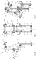
- the embodiment of a lifting and transport device 1 according to the invention shown in the figures has a frame 2, a holding device 3, a lifting device 4 and first, second and third supports 5, 6, 7.
- the lifting direction is designated 8 and the transport direction is designated 9.
- the frame 2 is formed from two frame parts 10, 11, which are arranged in the transport direction 9 in front of and behind a load space 12, which is designed to accommodate a clamping tool 13, and are perpendicular to the transport direction 9 from the flange top 14 along the flange -Extend the front side 15 to below the underside of the flange 16.
- the frame parts 10, 11 are connected to one another in a deformation-resistant manner by crossbars 17 running in the transport direction 9.
- the clear distance between the sections 10c, 11c of the frame parts 10, 11 arranged under the flange underside 16 is designed in the exemplary embodiment shown to accommodate a screw tensioning cylinder 13 ( Figures 4 and 5 ), which can be brought into engagement with a screw connection 18 to tighten it.
- the holding device 3 for the screw tensioning cylinder 13 is fastened in a vertically movable manner on these frame sections 10c, 11c.
- the invention is described here based on its use together with a screw tensioning cylinder 13.
- a lifting and transport device 1 according to the invention can also be used for any other automatic or manual clamping tool.
- each tensioning tool 13 is aligned in the holding device 3 in such a way that the means 19, which are to come into engagement with the screw connection 18 for pretensioning, are directed upwards, i.e. H. facing the screw connection 18, so that the engagement means 19 of the clamping tool 13 can be brought into engagement with the screw connection 18 to be preloaded by moving the holding device 3 upwards.
- a lever 20 is mounted as a lifting device 4 in an articulated manner about a first pivot axis 21, which extends in the transport direction 9.
- the lever 20 is U-shaped, with the legs 22 of the U extending perpendicular to the transport direction 9 and each being fastened to one of the two frame sections 10b, 11b by means of a first pivot bearing 23.
- the base of the U forms a handle 24 with which the lever 20 can be actuated.
- Each leg 22 of the U has a first lever section 20a, which extends from the pivot bearing 23 towards the load space side, and a second lever section 20b, which extends from the pivot bearing 23 towards the side facing away from the load space 12 and at its free end the handle 24 is attached.
- the holding device 3 is articulated by means of a second pivot bearing 25, the (second) pivot axis 26 of which runs parallel to the first pivot axis 21.
- the lifting device 4 also has two gas pressure cylinders 27, which are arranged in front of and behind the load space 12 in the transport direction 9 and one of which is fastened to one of the frame sections 10c, 11c under the flange underside 16.
- the gas pressure cylinders 27 run vertically and extend downwards beyond the lower end of said frame sections 10c, 11c. They are connected with their free, displaceable end 28 to the holding device 3, so that by vertically moving this end 28 of the two gas pressure cylinders 27, the holding device 3 with the clamping tool 13 attached to it can be moved vertically up or down.
- the gas pressure cylinders 27 are in operative connection with the lever 20, so that by appropriately actuating the lever 20, the gas pressure cylinders 27 are activated and the holding device 3 with the clamping tool 13 attached to it is raised into the clamping position or lowered into the transport position.
- the gas pressure cylinders 27 can be prestressed in the lowered transport position, with the prestressing force directed upwards, ie in the lifting direction 8, and designed so that it moves the clamping tool 13 including the holding device 3 away from the Can be raised to the transport position into the clamping position.
- the lowering from the clamping to the transport position and thus the pre-tensioning of the gas pressure cylinder 27 can then z. B. done manually by pressing down using the lever 20.
- a first roller 29 is rotatably mounted about an axis of rotation 30, which extends parallel to the flange top 14 or horizontally and perpendicular to the transport direction 9. Together, the first two rollers 29 form a first pair of rollers 29a, which in turn forms the first support 5 for the frame 2.
- a second roller 31 is rotatably mounted about an axis of rotation 32, which runs parallel to the flange end face 15 or vertically and perpendicular to the transport direction 9. Together, these two rollers 31 form a second pair of rollers 31a, which in turn forms the second support 6.
- Two adjustment devices 33 for the second rollers 31 are attached to the frame sections 10b, 11b running in front of the flange end face 15, to which these rollers 31 are attached and by means of which these rollers 31 can be moved for horizontal contact with the flange end face 15.
- a rectangularly curved sheet metal 34 is attached, which is designed to engage behind a screw connection, which is the is adjacent to the screw connection 18 to be preloaded.
- These angle plates 34 together form the third support 7, which introduces any forces acting horizontally perpendicular to the transport direction 9 into the flanges via the adjacent screw connections and thus prevents the lifting and transport device 1 from slipping off the flanges.
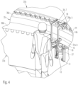
- FIG. 4 and 5 is the lifting and transport device 1 from the Figures 1 to 3 shown in use in producing a screwed flange connection 35.
- the flanges 36a, 36b of two cylindrical components 37a, 37b which are to be butted together, are to be screwed together.
- the first pair of rollers 29a rests on the top of the flange 14 between the screw connections and the flange edge 14a and the second pair of rollers 31a lies in the lower half of the flange face 15.
- the angle plates 34 of the third support 7 engage behind the top of the flange 14 and on the underside of the flange 16 the screw connections, which lie next to the screw connection 18 to be preloaded.
- a screw tensioning cylinder 13 is fastened as a clamping tool in the holding device 3 with an upwardly directed engagement means 19.
- the holding device 3 with the clamping tool 13 attached to it can now be raised into the clamping position - that is, raised to such an extent that the engagement means 19 comes or can be brought into engagement with the screw connection 18 to be preloaded - and also in the clamping position be held during the clamping process.
- the two gas pressure cylinders 27 are also activated, which support the lifting process with their preload force.
- the clamping tool 13 is released from the screw connection 18.
- the gas pressure cylinders 27 are pretensioned again and the holding device 3 and the clamping tool 13 attached to it are lowered to such an extent that the upper edge of the clamping tool 13 lies below the bolt end of the screw connection 18.
- the lifting and transport device 1 and with it the clamping tool 13 can now be freely moved or rolled to the next screw connection 18 to be preloaded. There the clamping tool 13 can be brought into engagement with the screw connection 18 by actuating the lever 20 again accordingly.
Landscapes
- Engineering & Computer Science (AREA)
- Mechanical Engineering (AREA)
- Life Sciences & Earth Sciences (AREA)
- Geology (AREA)
- Structural Engineering (AREA)
- Load-Engaging Elements For Cranes (AREA)
Applications Claiming Priority (1)
| Application Number | Priority Date | Filing Date | Title |
|---|---|---|---|
| DE102019200042.8A DE102019200042B3 (de) | 2019-01-04 | 2019-01-04 | Hebe- und Transportvorrichtung |
Publications (2)
| Publication Number | Publication Date |
|---|---|
| EP3677537A1 EP3677537A1 (de) | 2020-07-08 |
| EP3677537B1 true EP3677537B1 (de) | 2023-12-13 |
Family
ID=69159521
Family Applications (1)
| Application Number | Title | Priority Date | Filing Date |
|---|---|---|---|
| EP19219441.3A Active EP3677537B1 (de) | 2019-01-04 | 2019-12-23 | Hebe- und transportvorrichtung |
Country Status (5)
| Country | Link |
|---|---|
| US (1) | US11124399B2 (da) |
| EP (1) | EP3677537B1 (da) |
| DE (1) | DE102019200042B3 (da) |
| DK (1) | DK3677537T3 (da) |
| ES (1) | ES2969167T3 (da) |
Cited By (1)
| Publication number | Priority date | Publication date | Assignee | Title |
|---|---|---|---|---|
| EP4632221A1 (en) * | 2024-04-11 | 2025-10-15 | Siemens Gamesa Renewable Energy Innovation & Technology S.L. | Assembly aid and method for assembly of tower segments of a wind turbine tower |
Families Citing this family (6)
| Publication number | Priority date | Publication date | Assignee | Title |
|---|---|---|---|---|
| DE102022105559B3 (de) | 2022-03-09 | 2023-03-16 | Frank Hohmann | Hebe-und Transportvorrichtung |
| NL1044424B1 (en) | 2022-09-26 | 2024-04-03 | Intomechanics B V | Movable bolting tool for manipulating nut and bolt assemblies of a bolted flange assembly |
| US20260102858A1 (en) * | 2022-09-26 | 2026-04-16 | HYTORC Division Unex Corporation | Automated trolley system for tightening tower segments in wind turbines |
| DE102023119208B3 (de) | 2023-07-20 | 2025-01-02 | Frank Hohmann | Hebe- und Transportvorrichtung |
| DE102024127845B3 (de) * | 2024-09-25 | 2026-01-15 | Wagner Vermögensverwaltungs-GmbH & Co. KG | Hebe- und Transportvorrichtung zum Positionieren einer Schraubvorrichtung |
| CN119319428B (zh) * | 2024-12-18 | 2025-04-25 | 青岛布林瑞特机械有限公司 | 一种全自动船用花篮螺丝装配设备 |
Citations (1)
| Publication number | Priority date | Publication date | Assignee | Title |
|---|---|---|---|---|
| EP2660182A2 (de) * | 2012-05-02 | 2013-11-06 | Hohmann, Jörg | Hebe- und Transportvorrichtung |
Family Cites Families (4)
| Publication number | Priority date | Publication date | Assignee | Title |
|---|---|---|---|---|
| JPH08122479A (ja) * | 1994-10-27 | 1996-05-17 | Toshiba Corp | 原子炉格納容器上蓋のフランジボルト締付け方法とその装置 |
| JPH09295230A (ja) * | 1996-04-26 | 1997-11-18 | Tokyo Denki Komusho:Kk | 大型ナットの着脱装置 |
| KR101368670B1 (ko) | 2011-09-05 | 2014-03-06 | 삼성중공업 주식회사 | 풍력 발전기의 유지보수 로봇 |
| WO2016193297A1 (en) * | 2015-06-01 | 2016-12-08 | Total Wind A/S | Robot and working tool for performing assembly and maintenance operations in a sectioned tower |
-
2019
- 2019-01-04 DE DE102019200042.8A patent/DE102019200042B3/de active Active
- 2019-12-23 ES ES19219441T patent/ES2969167T3/es active Active
- 2019-12-23 DK DK19219441.3T patent/DK3677537T3/da active
- 2019-12-23 EP EP19219441.3A patent/EP3677537B1/de active Active
- 2019-12-23 US US16/724,489 patent/US11124399B2/en active Active
Patent Citations (1)
| Publication number | Priority date | Publication date | Assignee | Title |
|---|---|---|---|---|
| EP2660182A2 (de) * | 2012-05-02 | 2013-11-06 | Hohmann, Jörg | Hebe- und Transportvorrichtung |
Cited By (2)
| Publication number | Priority date | Publication date | Assignee | Title |
|---|---|---|---|---|
| EP4632221A1 (en) * | 2024-04-11 | 2025-10-15 | Siemens Gamesa Renewable Energy Innovation & Technology S.L. | Assembly aid and method for assembly of tower segments of a wind turbine tower |
| WO2025214769A1 (en) * | 2024-04-11 | 2025-10-16 | Siemens Gamesa Renewable Energy Innovation & Technology, S.L. | Assembly aid and method for assembly of tower segments of a wind turbine tower |
Also Published As
| Publication number | Publication date |
|---|---|
| EP3677537A1 (de) | 2020-07-08 |
| DK3677537T3 (da) | 2024-02-19 |
| US11124399B2 (en) | 2021-09-21 |
| DE102019200042B3 (de) | 2020-03-05 |
| US20200216296A1 (en) | 2020-07-09 |
| ES2969167T3 (es) | 2024-05-16 |
Similar Documents
| Publication | Publication Date | Title |
|---|---|---|
| EP3677537B1 (de) | Hebe- und transportvorrichtung | |
| EP3077133B1 (de) | Biegepresse | |
| EP0133634B1 (de) | Werkzeugspannvorrichtung | |
| DE3900078C2 (da) | ||
| DE3824563C2 (da) | ||
| DE4433731C2 (de) | Schraubvorrichtung | |
| EP4245457B1 (de) | Hebe- und transportvorrichtung | |
| DE3742296C2 (da) | ||
| DE102019219001A1 (de) | Hakenflasche für einen Kran | |
| EP0245704B1 (de) | Höhenverstellbare Stahlstütze für Deckenschalungen und dergl. | |
| WO2022214126A1 (de) | Handhabungsvorrichtung | |
| DE102020102910B3 (de) | Schraubzwinge | |
| DE102006062771A1 (de) | Hubstützenbock, insbesondere für einen Universaltragrahmen | |
| DE10129553B4 (de) | Schnellwechselsystem | |
| DE102023119208B3 (de) | Hebe- und Transportvorrichtung | |
| DE112016007111T5 (de) | Kabinenbefestigungseinrichtung für einen Aufzug | |
| DE29508758U1 (de) | Kran für Hubarbeitsbühne mit Knickauslegearm | |
| DE3515579C2 (de) | Tragbare Greifzange für Stücklasten | |
| AT523664B1 (de) | Transporthaken | |
| AT382851B (de) | Transportvorrichtung fuer sperrige, plattenfoermige bauteile | |
| EP3653809B1 (de) | Schalungssystem | |
| DE102024002996A1 (de) | Lastaufnahmevorrichtung | |
| DE19935902A1 (de) | Werkstück-Niederhaltevorrichtung | |
| DE10003406B4 (de) | Hebevorrichtung | |
| WO2024017707A1 (de) | Kletterschuh, klinkenvorrichtung, befestigungsteil und verfahren |
Legal Events
| Date | Code | Title | Description |
|---|---|---|---|
| PUAI | Public reference made under article 153(3) epc to a published international application that has entered the european phase |
Free format text: ORIGINAL CODE: 0009012 |
|
| STAA | Information on the status of an ep patent application or granted ep patent |
Free format text: STATUS: THE APPLICATION HAS BEEN PUBLISHED |
|
| AK | Designated contracting states |
Kind code of ref document: A1 Designated state(s): AL AT BE BG CH CY CZ DE DK EE ES FI FR GB GR HR HU IE IS IT LI LT LU LV MC MK MT NL NO PL PT RO RS SE SI SK SM TR |
|
| AX | Request for extension of the european patent |
Extension state: BA ME |
|
| STAA | Information on the status of an ep patent application or granted ep patent |
Free format text: STATUS: REQUEST FOR EXAMINATION WAS MADE |
|
| 17P | Request for examination filed |
Effective date: 20210105 |
|
| RBV | Designated contracting states (corrected) |
Designated state(s): AL AT BE BG CH CY CZ DE DK EE ES FI FR GB GR HR HU IE IS IT LI LT LU LV MC MK MT NL NO PL PT RO RS SE SI SK SM TR |
|
| GRAP | Despatch of communication of intention to grant a patent |
Free format text: ORIGINAL CODE: EPIDOSNIGR1 |
|
| STAA | Information on the status of an ep patent application or granted ep patent |
Free format text: STATUS: GRANT OF PATENT IS INTENDED |
|
| INTG | Intention to grant announced |
Effective date: 20230904 |
|
| GRAS | Grant fee paid |
Free format text: ORIGINAL CODE: EPIDOSNIGR3 |
|
| GRAA | (expected) grant |
Free format text: ORIGINAL CODE: 0009210 |
|
| STAA | Information on the status of an ep patent application or granted ep patent |
Free format text: STATUS: THE PATENT HAS BEEN GRANTED |
|
| AK | Designated contracting states |
Kind code of ref document: B1 Designated state(s): AL AT BE BG CH CY CZ DE DK EE ES FI FR GB GR HR HU IE IS IT LI LT LU LV MC MK MT NL NO PL PT RO RS SE SI SK SM TR |
|
| REG | Reference to a national code |
Ref country code: GB Ref legal event code: FG4D Free format text: NOT ENGLISH |
|
| REG | Reference to a national code |
Ref country code: CH Ref legal event code: EP |
|
| REG | Reference to a national code |
Ref country code: DE Ref legal event code: R096 Ref document number: 502019010125 Country of ref document: DE |
|
| REG | Reference to a national code |
Ref country code: IE Ref legal event code: FG4D Free format text: LANGUAGE OF EP DOCUMENT: GERMAN |
|
| REG | Reference to a national code |
Ref country code: DK Ref legal event code: T3 Effective date: 20240215 |
|
| PG25 | Lapsed in a contracting state [announced via postgrant information from national office to epo] |
Ref country code: GR Free format text: LAPSE BECAUSE OF FAILURE TO SUBMIT A TRANSLATION OF THE DESCRIPTION OR TO PAY THE FEE WITHIN THE PRESCRIBED TIME-LIMIT Effective date: 20240314 |
|
| REG | Reference to a national code |
Ref country code: LT Ref legal event code: MG9D |
|
| PG25 | Lapsed in a contracting state [announced via postgrant information from national office to epo] |
Ref country code: LT Free format text: LAPSE BECAUSE OF FAILURE TO SUBMIT A TRANSLATION OF THE DESCRIPTION OR TO PAY THE FEE WITHIN THE PRESCRIBED TIME-LIMIT Effective date: 20231213 |
|
| REG | Reference to a national code |
Ref country code: NL Ref legal event code: MP Effective date: 20231213 |
|
| PG25 | Lapsed in a contracting state [announced via postgrant information from national office to epo] |
Ref country code: LT Free format text: LAPSE BECAUSE OF FAILURE TO SUBMIT A TRANSLATION OF THE DESCRIPTION OR TO PAY THE FEE WITHIN THE PRESCRIBED TIME-LIMIT Effective date: 20231213 Ref country code: GR Free format text: LAPSE BECAUSE OF FAILURE TO SUBMIT A TRANSLATION OF THE DESCRIPTION OR TO PAY THE FEE WITHIN THE PRESCRIBED TIME-LIMIT Effective date: 20240314 Ref country code: BG Free format text: LAPSE BECAUSE OF FAILURE TO SUBMIT A TRANSLATION OF THE DESCRIPTION OR TO PAY THE FEE WITHIN THE PRESCRIBED TIME-LIMIT Effective date: 20240313 |
|
| REG | Reference to a national code |
Ref country code: ES Ref legal event code: FG2A Ref document number: 2969167 Country of ref document: ES Kind code of ref document: T3 Effective date: 20240516 |
|
| PG25 | Lapsed in a contracting state [announced via postgrant information from national office to epo] |
Ref country code: NL Free format text: LAPSE BECAUSE OF FAILURE TO SUBMIT A TRANSLATION OF THE DESCRIPTION OR TO PAY THE FEE WITHIN THE PRESCRIBED TIME-LIMIT Effective date: 20231213 |
|
| PG25 | Lapsed in a contracting state [announced via postgrant information from national office to epo] |
Ref country code: SE Free format text: LAPSE BECAUSE OF FAILURE TO SUBMIT A TRANSLATION OF THE DESCRIPTION OR TO PAY THE FEE WITHIN THE PRESCRIBED TIME-LIMIT Effective date: 20231213 Ref country code: RS Free format text: LAPSE BECAUSE OF FAILURE TO SUBMIT A TRANSLATION OF THE DESCRIPTION OR TO PAY THE FEE WITHIN THE PRESCRIBED TIME-LIMIT Effective date: 20231213 Ref country code: NO Free format text: LAPSE BECAUSE OF FAILURE TO SUBMIT A TRANSLATION OF THE DESCRIPTION OR TO PAY THE FEE WITHIN THE PRESCRIBED TIME-LIMIT Effective date: 20240313 Ref country code: NL Free format text: LAPSE BECAUSE OF FAILURE TO SUBMIT A TRANSLATION OF THE DESCRIPTION OR TO PAY THE FEE WITHIN THE PRESCRIBED TIME-LIMIT Effective date: 20231213 Ref country code: LV Free format text: LAPSE BECAUSE OF FAILURE TO SUBMIT A TRANSLATION OF THE DESCRIPTION OR TO PAY THE FEE WITHIN THE PRESCRIBED TIME-LIMIT Effective date: 20231213 Ref country code: HR Free format text: LAPSE BECAUSE OF FAILURE TO SUBMIT A TRANSLATION OF THE DESCRIPTION OR TO PAY THE FEE WITHIN THE PRESCRIBED TIME-LIMIT Effective date: 20231213 |
|
| PG25 | Lapsed in a contracting state [announced via postgrant information from national office to epo] |
Ref country code: IS Free format text: LAPSE BECAUSE OF FAILURE TO SUBMIT A TRANSLATION OF THE DESCRIPTION OR TO PAY THE FEE WITHIN THE PRESCRIBED TIME-LIMIT Effective date: 20240413 |
|
| PG25 | Lapsed in a contracting state [announced via postgrant information from national office to epo] |
Ref country code: CZ Free format text: LAPSE BECAUSE OF FAILURE TO SUBMIT A TRANSLATION OF THE DESCRIPTION OR TO PAY THE FEE WITHIN THE PRESCRIBED TIME-LIMIT Effective date: 20231213 |
|
| PG25 | Lapsed in a contracting state [announced via postgrant information from national office to epo] |
Ref country code: SK Free format text: LAPSE BECAUSE OF FAILURE TO SUBMIT A TRANSLATION OF THE DESCRIPTION OR TO PAY THE FEE WITHIN THE PRESCRIBED TIME-LIMIT Effective date: 20231213 |
|
| PG25 | Lapsed in a contracting state [announced via postgrant information from national office to epo] |
Ref country code: SM Free format text: LAPSE BECAUSE OF FAILURE TO SUBMIT A TRANSLATION OF THE DESCRIPTION OR TO PAY THE FEE WITHIN THE PRESCRIBED TIME-LIMIT Effective date: 20231213 Ref country code: SK Free format text: LAPSE BECAUSE OF FAILURE TO SUBMIT A TRANSLATION OF THE DESCRIPTION OR TO PAY THE FEE WITHIN THE PRESCRIBED TIME-LIMIT Effective date: 20231213 Ref country code: RO Free format text: LAPSE BECAUSE OF FAILURE TO SUBMIT A TRANSLATION OF THE DESCRIPTION OR TO PAY THE FEE WITHIN THE PRESCRIBED TIME-LIMIT Effective date: 20231213 Ref country code: IT Free format text: LAPSE BECAUSE OF FAILURE TO SUBMIT A TRANSLATION OF THE DESCRIPTION OR TO PAY THE FEE WITHIN THE PRESCRIBED TIME-LIMIT Effective date: 20231213 Ref country code: IS Free format text: LAPSE BECAUSE OF FAILURE TO SUBMIT A TRANSLATION OF THE DESCRIPTION OR TO PAY THE FEE WITHIN THE PRESCRIBED TIME-LIMIT Effective date: 20240413 Ref country code: EE Free format text: LAPSE BECAUSE OF FAILURE TO SUBMIT A TRANSLATION OF THE DESCRIPTION OR TO PAY THE FEE WITHIN THE PRESCRIBED TIME-LIMIT Effective date: 20231213 Ref country code: CZ Free format text: LAPSE BECAUSE OF FAILURE TO SUBMIT A TRANSLATION OF THE DESCRIPTION OR TO PAY THE FEE WITHIN THE PRESCRIBED TIME-LIMIT Effective date: 20231213 |
|
| REG | Reference to a national code |
Ref country code: CH Ref legal event code: PL |
|
| PG25 | Lapsed in a contracting state [announced via postgrant information from national office to epo] |
Ref country code: PL Free format text: LAPSE BECAUSE OF FAILURE TO SUBMIT A TRANSLATION OF THE DESCRIPTION OR TO PAY THE FEE WITHIN THE PRESCRIBED TIME-LIMIT Effective date: 20231213 Ref country code: PT Free format text: LAPSE BECAUSE OF FAILURE TO SUBMIT A TRANSLATION OF THE DESCRIPTION OR TO PAY THE FEE WITHIN THE PRESCRIBED TIME-LIMIT Effective date: 20240415 |
|
| PG25 | Lapsed in a contracting state [announced via postgrant information from national office to epo] |
Ref country code: LU Free format text: LAPSE BECAUSE OF NON-PAYMENT OF DUE FEES Effective date: 20231223 |
|
| REG | Reference to a national code |
Ref country code: BE Ref legal event code: MM Effective date: 20231231 |
|
| PG25 | Lapsed in a contracting state [announced via postgrant information from national office to epo] |
Ref country code: PT Free format text: LAPSE BECAUSE OF FAILURE TO SUBMIT A TRANSLATION OF THE DESCRIPTION OR TO PAY THE FEE WITHIN THE PRESCRIBED TIME-LIMIT Effective date: 20240415 Ref country code: PL Free format text: LAPSE BECAUSE OF FAILURE TO SUBMIT A TRANSLATION OF THE DESCRIPTION OR TO PAY THE FEE WITHIN THE PRESCRIBED TIME-LIMIT Effective date: 20231213 Ref country code: LU Free format text: LAPSE BECAUSE OF NON-PAYMENT OF DUE FEES Effective date: 20231223 |
|
| REG | Reference to a national code |
Ref country code: DE Ref legal event code: R097 Ref document number: 502019010125 Country of ref document: DE |
|
| PG25 | Lapsed in a contracting state [announced via postgrant information from national office to epo] |
Ref country code: MC Free format text: LAPSE BECAUSE OF FAILURE TO SUBMIT A TRANSLATION OF THE DESCRIPTION OR TO PAY THE FEE WITHIN THE PRESCRIBED TIME-LIMIT Effective date: 20231213 |
|
| REG | Reference to a national code |
Ref country code: IE Ref legal event code: MM4A |
|
| PG25 | Lapsed in a contracting state [announced via postgrant information from national office to epo] |
Ref country code: IE Free format text: LAPSE BECAUSE OF NON-PAYMENT OF DUE FEES Effective date: 20231223 |
|
| PG25 | Lapsed in a contracting state [announced via postgrant information from national office to epo] |
Ref country code: BE Free format text: LAPSE BECAUSE OF NON-PAYMENT OF DUE FEES Effective date: 20231231 |
|
| PLBE | No opposition filed within time limit |
Free format text: ORIGINAL CODE: 0009261 |
|
| STAA | Information on the status of an ep patent application or granted ep patent |
Free format text: STATUS: NO OPPOSITION FILED WITHIN TIME LIMIT |
|
| PG25 | Lapsed in a contracting state [announced via postgrant information from national office to epo] |
Ref country code: CH Free format text: LAPSE BECAUSE OF NON-PAYMENT OF DUE FEES Effective date: 20231231 |
|
| PG25 | Lapsed in a contracting state [announced via postgrant information from national office to epo] |
Ref country code: SI Free format text: LAPSE BECAUSE OF FAILURE TO SUBMIT A TRANSLATION OF THE DESCRIPTION OR TO PAY THE FEE WITHIN THE PRESCRIBED TIME-LIMIT Effective date: 20231213 |
|
| PG25 | Lapsed in a contracting state [announced via postgrant information from national office to epo] |
Ref country code: SI Free format text: LAPSE BECAUSE OF FAILURE TO SUBMIT A TRANSLATION OF THE DESCRIPTION OR TO PAY THE FEE WITHIN THE PRESCRIBED TIME-LIMIT Effective date: 20231213 Ref country code: IE Free format text: LAPSE BECAUSE OF NON-PAYMENT OF DUE FEES Effective date: 20231223 Ref country code: CH Free format text: LAPSE BECAUSE OF NON-PAYMENT OF DUE FEES Effective date: 20231231 Ref country code: BE Free format text: LAPSE BECAUSE OF NON-PAYMENT OF DUE FEES Effective date: 20231231 |
|
| 26N | No opposition filed |
Effective date: 20240916 |
|
| GBPC | Gb: european patent ceased through non-payment of renewal fee |
Effective date: 20240313 |
|
| PG25 | Lapsed in a contracting state [announced via postgrant information from national office to epo] |
Ref country code: GB Free format text: LAPSE BECAUSE OF NON-PAYMENT OF DUE FEES Effective date: 20240313 |
|
| PG25 | Lapsed in a contracting state [announced via postgrant information from national office to epo] |
Ref country code: FR Free format text: LAPSE BECAUSE OF NON-PAYMENT OF DUE FEES Effective date: 20240213 |
|
| PG25 | Lapsed in a contracting state [announced via postgrant information from national office to epo] |
Ref country code: GB Free format text: LAPSE BECAUSE OF NON-PAYMENT OF DUE FEES Effective date: 20240313 Ref country code: FR Free format text: LAPSE BECAUSE OF NON-PAYMENT OF DUE FEES Effective date: 20240213 |
|
| PG25 | Lapsed in a contracting state [announced via postgrant information from national office to epo] |
Ref country code: FI Free format text: LAPSE BECAUSE OF FAILURE TO SUBMIT A TRANSLATION OF THE DESCRIPTION OR TO PAY THE FEE WITHIN THE PRESCRIBED TIME-LIMIT Effective date: 20231213 |
|
| PG25 | Lapsed in a contracting state [announced via postgrant information from national office to epo] |
Ref country code: CY Free format text: LAPSE BECAUSE OF FAILURE TO SUBMIT A TRANSLATION OF THE DESCRIPTION OR TO PAY THE FEE WITHIN THE PRESCRIBED TIME-LIMIT; INVALID AB INITIO Effective date: 20191223 |
|
| PG25 | Lapsed in a contracting state [announced via postgrant information from national office to epo] |
Ref country code: HU Free format text: LAPSE BECAUSE OF FAILURE TO SUBMIT A TRANSLATION OF THE DESCRIPTION OR TO PAY THE FEE WITHIN THE PRESCRIBED TIME-LIMIT; INVALID AB INITIO Effective date: 20191223 |
|
| PG25 | Lapsed in a contracting state [announced via postgrant information from national office to epo] |
Ref country code: TR Free format text: LAPSE BECAUSE OF FAILURE TO SUBMIT A TRANSLATION OF THE DESCRIPTION OR TO PAY THE FEE WITHIN THE PRESCRIBED TIME-LIMIT Effective date: 20231213 |
|
| REG | Reference to a national code |
Ref country code: DE Ref legal event code: R082 Ref document number: 502019010125 Country of ref document: DE Representative=s name: ALPSPITZ IP ALLGAYER UND PARTNER PATENTANWAELT, DE |
|
| PGFP | Annual fee paid to national office [announced via postgrant information from national office to epo] |
Ref country code: DE Payment date: 20251211 Year of fee payment: 7 |
|
| PGFP | Annual fee paid to national office [announced via postgrant information from national office to epo] |
Ref country code: DK Payment date: 20251224 Year of fee payment: 7 |
|
| REG | Reference to a national code |
Ref country code: AT Ref legal event code: MM01 Ref document number: 1640307 Country of ref document: AT Kind code of ref document: T Effective date: 20241223 |
|
| PGFP | Annual fee paid to national office [announced via postgrant information from national office to epo] |
Ref country code: ES Payment date: 20260130 Year of fee payment: 7 |
|
| PG25 | Lapsed in a contracting state [announced via postgrant information from national office to epo] |
Ref country code: AT Free format text: LAPSE BECAUSE OF NON-PAYMENT OF DUE FEES Effective date: 20241223 |
|
| PGFP | Annual fee paid to national office [announced via postgrant information from national office to epo] |
Ref country code: AT Payment date: 20260410 Year of fee payment: 5 |