EP3680055A1 - Haltevorrichtung und satz aus haltevorrichtungen für doppelwirkungs-reibrührpunktschweissen, vorrichtung für doppelwirkungs-reibrührpunktschweissverfahren und verfahren für doppelwirkungs-reibrührpunktschweissverfahren - Google Patents
Haltevorrichtung und satz aus haltevorrichtungen für doppelwirkungs-reibrührpunktschweissen, vorrichtung für doppelwirkungs-reibrührpunktschweissverfahren und verfahren für doppelwirkungs-reibrührpunktschweissverfahren Download PDFInfo
- Publication number
- EP3680055A1 EP3680055A1 EP18854125.4A EP18854125A EP3680055A1 EP 3680055 A1 EP3680055 A1 EP 3680055A1 EP 18854125 A EP18854125 A EP 18854125A EP 3680055 A1 EP3680055 A1 EP 3680055A1
- Authority
- EP
- European Patent Office
- Prior art keywords
- workpiece
- spot welding
- friction stir
- stir spot
- double
- Prior art date
- Legal status (The legal status is an assumption and is not a legal conclusion. Google has not performed a legal analysis and makes no representation as to the accuracy of the status listed.)
- Granted
Links
Images




Classifications
-
- B—PERFORMING OPERATIONS; TRANSPORTING
- B23—MACHINE TOOLS; METAL-WORKING NOT OTHERWISE PROVIDED FOR
- B23K—SOLDERING OR UNSOLDERING; WELDING; CLADDING OR PLATING BY SOLDERING OR WELDING; CUTTING BY APPLYING HEAT LOCALLY, e.g. FLAME CUTTING; WORKING BY LASER BEAM
- B23K20/00—Non-electric welding by applying impact or other pressure, with or without the application of heat, e.g. cladding or plating
- B23K20/12—Non-electric welding by applying impact or other pressure, with or without the application of heat, e.g. cladding or plating the heat being generated by friction; Friction welding
- B23K20/122—Non-electric welding by applying impact or other pressure, with or without the application of heat, e.g. cladding or plating the heat being generated by friction; Friction welding using a non-consumable tool, e.g. friction stir welding
-
- B—PERFORMING OPERATIONS; TRANSPORTING
- B23—MACHINE TOOLS; METAL-WORKING NOT OTHERWISE PROVIDED FOR
- B23K—SOLDERING OR UNSOLDERING; WELDING; CLADDING OR PLATING BY SOLDERING OR WELDING; CUTTING BY APPLYING HEAT LOCALLY, e.g. FLAME CUTTING; WORKING BY LASER BEAM
- B23K20/00—Non-electric welding by applying impact or other pressure, with or without the application of heat, e.g. cladding or plating
- B23K20/12—Non-electric welding by applying impact or other pressure, with or without the application of heat, e.g. cladding or plating the heat being generated by friction; Friction welding
- B23K20/122—Non-electric welding by applying impact or other pressure, with or without the application of heat, e.g. cladding or plating the heat being generated by friction; Friction welding using a non-consumable tool, e.g. friction stir welding
- B23K20/1225—Particular aspects of welding with a non-consumable tool
-
- B—PERFORMING OPERATIONS; TRANSPORTING
- B23—MACHINE TOOLS; METAL-WORKING NOT OTHERWISE PROVIDED FOR
- B23K—SOLDERING OR UNSOLDERING; WELDING; CLADDING OR PLATING BY SOLDERING OR WELDING; CUTTING BY APPLYING HEAT LOCALLY, e.g. FLAME CUTTING; WORKING BY LASER BEAM
- B23K20/00—Non-electric welding by applying impact or other pressure, with or without the application of heat, e.g. cladding or plating
- B23K20/12—Non-electric welding by applying impact or other pressure, with or without the application of heat, e.g. cladding or plating the heat being generated by friction; Friction welding
- B23K20/122—Non-electric welding by applying impact or other pressure, with or without the application of heat, e.g. cladding or plating the heat being generated by friction; Friction welding using a non-consumable tool, e.g. friction stir welding
- B23K20/1245—Non-electric welding by applying impact or other pressure, with or without the application of heat, e.g. cladding or plating the heat being generated by friction; Friction welding using a non-consumable tool, e.g. friction stir welding characterised by the apparatus
-
- B—PERFORMING OPERATIONS; TRANSPORTING
- B23—MACHINE TOOLS; METAL-WORKING NOT OTHERWISE PROVIDED FOR
- B23K—SOLDERING OR UNSOLDERING; WELDING; CLADDING OR PLATING BY SOLDERING OR WELDING; CUTTING BY APPLYING HEAT LOCALLY, e.g. FLAME CUTTING; WORKING BY LASER BEAM
- B23K20/00—Non-electric welding by applying impact or other pressure, with or without the application of heat, e.g. cladding or plating
- B23K20/12—Non-electric welding by applying impact or other pressure, with or without the application of heat, e.g. cladding or plating the heat being generated by friction; Friction welding
- B23K20/122—Non-electric welding by applying impact or other pressure, with or without the application of heat, e.g. cladding or plating the heat being generated by friction; Friction welding using a non-consumable tool, e.g. friction stir welding
- B23K20/1245—Non-electric welding by applying impact or other pressure, with or without the application of heat, e.g. cladding or plating the heat being generated by friction; Friction welding using a non-consumable tool, e.g. friction stir welding characterised by the apparatus
- B23K20/126—Workpiece support, i.e. backing or clamping
-
- B—PERFORMING OPERATIONS; TRANSPORTING
- B23—MACHINE TOOLS; METAL-WORKING NOT OTHERWISE PROVIDED FOR
- B23K—SOLDERING OR UNSOLDERING; WELDING; CLADDING OR PLATING BY SOLDERING OR WELDING; CUTTING BY APPLYING HEAT LOCALLY, e.g. FLAME CUTTING; WORKING BY LASER BEAM
- B23K20/00—Non-electric welding by applying impact or other pressure, with or without the application of heat, e.g. cladding or plating
- B23K20/12—Non-electric welding by applying impact or other pressure, with or without the application of heat, e.g. cladding or plating the heat being generated by friction; Friction welding
- B23K20/122—Non-electric welding by applying impact or other pressure, with or without the application of heat, e.g. cladding or plating the heat being generated by friction; Friction welding using a non-consumable tool, e.g. friction stir welding
- B23K20/1265—Non-butt welded joints, e.g. overlap-joints, T-joints or spot welds
Definitions
- the present invention relates to a holding jig and a holding jig set that are used for double-acting friction stir spot welding and hold a workpiece, a double-acting friction stir spot welding device using the holding jig and the holding jig set, and a double-acting friction stir spot welding method.
- Double-acting friction stir spot welding uses, as a rotary tool, a substantially cylindrical pin member and a substantially cylindrical shoulder member having a hollow for the insertion of the pin member.
- the pin member and the shoulder member can rotate and advance/retract independently.
- These rotary tools are pressed (press-fitted) into workpieces such as a metal material.
- the workpieces are softened and stirred by using frictional heat with the workpieces, thereby welding the workpieces to each other.
- a clamp member that presses and supports a workpiece is often used.
- a double-acting friction stir spot welding device configured to include a cylindrical clamp member that is located outside the shoulder member and has a hollow like the shoulder member. Because the clamp member can stably support a workpiece by pressing the workpiece, the pin member or shoulder member that rotates at high speed can be properly pressed into the workpiece.
- the welding tools disclosed in Patent Literatures 1 and 2 are configured such that the substantially cylindrical shoulder member is located on the outer periphery of the pin member, and the substantially cylindrical clamp member is located on the outer periphery of the shoulder member.
- the welding tools have a nested structure in which the clamp member, the shoulder member, and the pin member are arranged concentrically.
- the present invention has been made to solve such a problem, and has as its object to provide double-acting friction stir spot welding that can achieve an improvement in the strength of the joint portion where workpieces are welded.
- a holding jig for double-acting friction stir spot welding is a holding jig which is used for a friction stir spot welding device for welding a workpiece by partially stirring the workpiece with rotary tools and is configured to hold the workpiece.
- the friction stir spot welding device includes, as the rotary tools, a cylindrical pin member that is configured to rotate around an axis and be movable forward and backward along the axis and a cylindrical shoulder member that is positioned so as to surround an outside of the pin member and is configured to rotate around the axis of the pin member and be movable forward and backward along the axis.
- the holding jig is a clamp member that has a cylindrical shape positioned so as to surround an outside of the shoulder member and is configured to press the workpiece from an obverse surface with an annular pressing surface of a distal end of the clamp member.
- the clamp member has an inclined surface that is adjacent to an inner edge portion of the pressing surface and inclined so as to reduce an inner diameter of the clamp member toward a back side as viewed from the pressing surface.
- a tapered inclined surface is formed inside the pressing surface of the clamp member, and a concave region whose periphery is covered with the clamp member is formed on the distal end portions of the rotary tools by aligning the contact surface of the shoulder member with the upper edge of the inclined surface.
- the press-fitting of the shoulder member stirs the material located immediately below the contact surface of the shoulder member, whereas the surrounding material adjacent to the contact surface of the shoulder member is not stirred but softened to some extent. Accordingly, not only the material stirred with the press-fitting of the shoulder member but also the surrounding softened material can be filled into the concave region.
- stirred portion boundary is a stress concentration portion and is a region that tends to be a starting point of fracture. Therefore, the acting stress can be relieved and the rigidity of the welded portion can be improved. As a result, it is possible to further improve the strength of, for example, the joint portion of the workpiece.
- a holding jig set for double-acting friction stir spot welding is a holding jig set used for the double-acting friction stir spot welding device and configured to hold the workpiece.
- the holding jig set includes the holding jig for a double-acting friction stir spot welding device having the above configuration and a backing member that is positioned on an advancing direction side of the rotary tools and supports a reverse surface of the workpiece on a supporting surface with the obverse surface of the workpiece facing the rotary tools.
- a circular concave portion having a peripheral edge portion that is an inclined surface inclined so as to reduce a diameter from the supporting surface toward a depth direction is formed in the supporting surface of the backing member.
- a concave region can be formed in the obverse surface side of a workpiece with the clamp member and the rotary tools
- a concave region can also be formed in the reverse surface side of the workpiece by the concave portion in the supporting surface of the backing member.
- a double-acting friction stir spot welding device includes the holding jig for double-acting friction stir spot welding which has the above configuration or the holding jig set for double-acting friction stir spot welding which has the above configuration.
- a double-acting friction stir spot welding method is a double-acting friction stir spot welding method of welding a workpiece held by a holding jig by partially stirring the workpiece with rotary tools.
- a cylindrical pin member that is configured to rotate around an axis and be movable forward and backward along the axis and a cylindrical shoulder member that is positioned so as to surround an outside of the pin member and is configured to rotate around the axis of the pin member and be movable forward and backward along the axis are used as the rotary tools in a forward/backward movable state.
- a clamp member that has a cylindrical shape positioned so as to surround an outside of the shoulder member and is configured to press the workpiece from an obverse surface with an annular pressing surface of a distal end of the clamp member is used as the holding jig.
- the clamp member has an inclined surface that is adjacent to an inner edge portion of the pressing surface and inclined so as to reduce an inner diameter of the clamp member toward a back side as viewed from the pressing surface.
- the method includes aligning a contact surface of the shoulder member with an upper edge of the inclined surface of the clamp member to form a concave region by at least the inclined surface and the contact surface, and filling the concave region with a material constituting the workpiece.
- the present invention has the effect of providing double-acting friction stir spot welding that can achieve an improvement in the strength of the joint portion where workpieces are welded.
- a double-acting friction stir spot welding device or double-acting friction stir spot welding method will be simply abbreviated as a friction stir spot welding device or friction stir spot welding method.
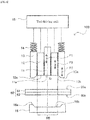
- a friction stir spot welding device 10A includes, as main components, a pin member 11 and a shoulder member 12 that are rotary tools, a clamp member 13 that is a holding jig, a spring 14 that applies an urging force to the clamp member 13, a tool driving unit 15 that drives the rotary tools, and a backing member 16 that supports a workpiece 60.
- the pin member 11 is substantially cylindrical or substantially columnar and is supported by a tool fixing portion (not shown).
- the pin member 11 is configured to be driven by the tool driving unit 15 to rotate around an axis Xr (the rotary axis indicated by the chain line in Fig. 1 ) and to advance and retract along the direction indicated by a broken-line arrow PI, i.e., the direction of the axis Xr (the vertical direction in Fig. 1 ).
- the shoulder member 12 is substantially cylindrical and has a hollow center in which the pin member 11 is inserted.
- the shoulder member 12 is supported by the tool fixing portion, such that the shoulder member 12 surrounds the pin member 11 at the outside of the pin member 11.
- the shoulder member 12 is configured to be driven by the tool driving unit 15 to rotate around the axis Xr, which is the same axis around which the pin member 11 rotates, and to advance and retract along the direction indicated by a broken-line arrow P2, i.e., the direction of the axis Xr.
- both the pin member 11 and the shoulder member 12 are supported by the same tool fixing portion, and driven by the tool driving unit 15 to integrally rotate around the axis Xr.
- the pin member 11 and the shoulder member 12 are configured to be driven by the tool driving unit 15 to advance and retract along the direction of the axis Xr independently of each other.
- the pin member 11 and the shoulder member 12 respectively include a contact surface 11a and a contact surface 12a at their distal ends, which come into contact with the workpiece 60.
- the contact surface 11a of the pin member 11 is referred to as the pin contact surface 11a
- the contact surface 12a of the shoulder member 12 is referred to as the shoulder contact surface 12a.
- the clamp member 13 is provided outside the shoulder member 12. Similar to the shoulder member 12, the clamp member 13 is cylindrical and has a hollow center in which the shoulder member 12 is inserted. Accordingly, the substantially cylindrical shoulder member 12 is positioned around the outer periphery of the pin member 11, and the substantially cylindrical clamp member 13 is positioned around the outer periphery of the shoulder member 12. In other words, the clamp member 13, the shoulder member 12, and the pin member 11 constitute a nested structure, in which these components are arranged concentrically.
- the clamp member 13 presses the workpiece 60 from one surface (obverse surface).
- the clamp member 13 presses and holds the workpiece 60 in order to implement good friction stir spot welding. Therefore, the clamp member 13 is a holding jig in the friction stir spot welding device 10A.
- the clamp member 13 is supported by a tool fixing portion (not shown) through the spring 14, and hence is biased toward the backing member 16.
- the clamp member 13 is configured to be advanced and retracted by the tool driving unit 15 along the direction of a broken-line arrow P3 (the same direction as the broken-line arrows P1 and P2), that is, the direction of the axis Xr as with the pin member 11 or the shoulder member 12. Similar to the pin member 11 and the shoulder member 12 that are rotary tools, the clamp member 13 includes, at its distal end, a pressing surface 13a that presses the workpiece 60.
- the clamp member 13 has a cylindrical shape positioned so as to surround the outside of the shoulder member 12, the pressing surface 13a is an annular surface. Further, as shown in Fig. 1 , the clamp member 13 has an inclined surface 13b that is adjacent to the inner edge portion of the pressing surface 13a and inclined so as to reduce the inner diameter of the clamp member 13 toward the back side as viewed from the pressing surface 13a. Therefore, the clamp member 13 has a cylindrical shape, most of which has the same inner diameter and outer diameter except for the distal end portion, with only the distal end portion being tapered such that the outer diameter is maintained and the inner diameter increases toward the distal end side.
- the inclined surface 13b shown in Fig. 1 is formed by chamfering the inner virtual edge portion of the virtual pressing surface of the distal end portion of the clamp member 13. It can also be said that the inclined surface 13b is a tapered surface whose inner diameter is large at the distal end portion of the clamp member 13.
- the specific configuration of the inclined surface 13b of the clamp member 13 is not particularly limited.
- the inclined surface 13b only needs to be an inclined surface with the inner diameter of the clamp member 13 decreasing toward the back side as viewed from the pressing surface 13a. Therefore, the inclined surface 13b may be a flat surface (plane) as schematically shown in Fig. 1 , or may be a curved surface. Further, the inclined surface 13b may be configured by a single plane as shown in Fig. 1 , but may be configured by a plurality of planes adjacent to each other or a plurality of curved surfaces adjacent to each other, or may be configured to include both a flat surface and a curved surface.
- the height of the inclined surface 13b with respect to the pressing surface 13a, the expanding width of the inclined surface 13b with reference to the inner peripheral surface of the shoulder member 12, the inclination angle of the inclined surface 13b, the width of the inclined surface 13b itself (spacing), and the like are not specifically limited. These numerical values can be appropriately set according to various conditions (especially, the thickness of the thick region described later) required for the welded portion formed on the workpiece 60.
- the tool driving unit 15 rotates the pin member 11 and the shoulder member 12 as rotary tools independently of each other, and moves the rotary tools and the clamp member 13 as a holding jig forward and backward independently of each other.
- the specific configuration is not particularly limited, and a known configuration can be suitably used.
- Fig. 1 schematically shows the tool driving unit 15 as a block. Further, Fig. 1 schematically shows the driving (rotation driving, forward/backward movement, and other types of driving) of the pin member 11, the shoulder member 12, and the clamp member 13 by the tool driving unit 15 by connecting the block of the tool driving unit 15 to the rotary tools and the holding jig with dotted lines.
- the tool driving unit 15 may be configured to drive the rotary tools (the pin member 11 and the shoulder member 12) but not to move the clamp member 13 as a holding jig forward and backward. That is, the friction stir spot welding device 10A may include a jig driving unit that drives the clamp member 13 separately from the tool driving unit 15 that drives only the rotary tools. Moreover, the tool driving unit 15 may be configured to be controlled via a control unit (not shown).
- the backing member 16 is positioned on the advancing direction (axis Xr direction) side of the pin member 11 and the shoulder member 12 (and the clamp member 13). In other words, the backing member 16 is positioned so as to face the rotary tools and the clamp member 13.
- the configuration of the backing member 16 is not particularly limited, so long as the backing member 16 is configured to properly support the workpiece 60 so that friction stir spot welding can be performed on the workpiece 60.
- the specific configuration of the workpiece 60 is not particularly limited, and various configurations are assumed.
- Embodiment 1 as shown in Fig. 1 , for the convenience of explaining friction stir spot welding, as the workpiece 60, an example in which two planar workpieces 61 and 62 are stacked is illustrated. These two workpieces 61 and 62 are supported on a supporting surface 16a of the backing member 16. Therefore, in Embodiment 1, as the backing member 16, a configuration having a flat supporting surface 16a that stably supports the two workpieces 61 and 62 is illustrated.
- the workpiece 61 facing the rotary tools will be referred to as the front-side workpiece 61
- the workpiece 62 supported on the flat supporting surface 16a will be referred to as the back-side workpiece 62.
- the surface of the front-side workpiece 61 which faces the rotary tools will be referred to as an "obverse surface 60a" of the workpiece 60
- the surface of the back-side workpiece 62 which is supported on the supporting surface 16a will be referred to as a "reverse surface 60b" of the workpiece 60.
- the supporting surface 16a of the backing member 16 supports the reverse surface 60b of the workpiece 60 while the obverse surface 60a of the workpiece 60 faces the rotary tools (the pin member 11 and the shoulder member 12). If one surface of each of the two workpieces 61 and 62 is the first surface and the other surface is the second surface, the first surface of the front-side workpiece 61 is the obverse surface 60a. Further, the two workpieces 61 and 62 are overlapped such that the second surface of the front-side workpiece 61 comes into contact with the first surface of the back-side workpiece 62. Further, the second surface of the back-side workpiece 62 is the reverse surface 60b and is supported by the supporting surface 16a of the backing member 16.
- the specific configuration provided for the friction stir spot welding device 10A is not particularly limited.
- the friction stir spot welding device 10A is configured to include a C-shaped frame, the rotary tools, the clamp member 13, the tool driving unit 15, and the like are provided on the upper portion of the C-shaped frame, and the backing member 16 is provided on the lower portion of the C-shaped frame so as to face the rotary tools, the clamp member 13, the tool driving unit 15, and the like.
- the backing member 16 may be fixed undetachably to the C-shaped frame or may be detachably attached.
- the specific configuration of the friction stir spot welding device 10A according to Embodiment 1 is not particularly limited. As described above, the friction stir spot welding device 10A may have another known configuration as long as including the pin member 11 and the shoulder member 12, which are rotary tools, the clamp member 13, the tool driving unit 15, and the backing member 16. Further, if the backing member 16 is detachable, the friction stir spot welding device 10A does not necessarily include the backing member 16.
- the friction stir spot welding device 10A including the backing member 16 may be provided at the distal end of an arm of the robot device through a C-shaped frame.
- the robot device provided with the friction stir spot welding device 10A not provided with the backing member 16 and the robot device provided with the backing member 16 may be configured to face each other.
- the backing member 16 holds the workpiece 60 that performs friction stir spot welding with the rotary tools together with the clamp member 13. Therefore, the backing member 16 is also a holding jig of the friction stir spot welding device 10A. If the clamp member 13 is the first holding jig, the backing member 16 can be the second holding jig. As described above, the backing member 16 can be detachably provided for the friction stir spot welding device 10A, and the clamp member 13 may also be detachably provided for the friction stir spot welding device 10A. In this case, the clamp member 13 and the backing member 16 can be a holding jig set for the friction stir spot welding device 10A.
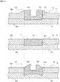
- FIG. 2A to 2C show the space region formed by the inclined surface 13b of the clamp member 13 and the obverse surface 60a of the workpiece 60 in the friction stir spot welding device 10A according to the present disclosure.
- Figs. 2A to 2C show the rotary tools and the clamp member 13 in the main configuration of the friction stir spot welding device 10A shown in Fig. 1 , with the obverse surface 60a of the workpiece 60 being indicated by a dotted line.
- the inclined surface 13b of the clamp member 13 is configured as a tapered surface that is adjacent to the inner edge portion of the pressing surface 13a and expands toward the distal end side.
- the pin member 11 and the shoulder member 12 are moved forward and backward to bring the shoulder contact surface 12a and the pin contact surface 11a into contact with the obverse surface 60a of the workpiece 60.
- a space region S0 surrounded by a broken line in Fig. 2A is formed between the inclined surface 13b, the outer peripheral surface of the shoulder member 12 and the obverse surface 60a of the workpiece 60.
- the space region S0 can be said to be a gap that is inevitably formed between the outer peripheral surface of the shoulder member 12 and the clamp member 13 when the clamp member 13 has the inclined surface 13b. Therefore, for the sake of convenience, the space region S0 will be referred to as the "gap region S0".
- a space region S1 surrounded by a broken line in Fig. 2B is formed between the inclined surface 13b, the shoulder contact surface 12a, the outer peripheral surface of the pin member 11 and the obverse surface 60a of the workpiece 60.
- the pin contact surface 11a is press-fitted into the obverse surface 60a (or the pin member 11 may be in contact with the obverse surface 60a of the workpiece 60). Therefore, the shape of the space region S1 is an annular shape.
- the space region S1 can be regarded as a concave region formed by the rotary tools and the clamp member 13. Therefore, for the sake of convenience, the space region S1 will be referred to as the "annular concave region S1".
- a space region S2 surrounded by a broken line in Fig. 2C is formed between the inclined surface 13b, the shoulder contact surface 12a, and the pin contact surface 11a and the obverse surface 60a of the workpiece 60.
- the space region S2 is a concave region similar to the annular concave region S1, but its shape is not an annular shape but a circular shape. Therefore, for the sake of convenience, the space region S2 will be referred to as the "circular concave region S2".
- the material constituting the workpiece 60 is filled into the annular concave region S1 shown in Fig. 2B or the circular concave region S2 shown in Fig. 2C .
- FIG. 3A to 3D A typical configuration of the friction stir spot welding method according to the present disclosure will be described in detail next with reference to Figs. 3A to 3D , Fig. 4 , and Figs. 5A and 5B with the above friction stir spot welding device 10A taken as an example.
- the contact surfaces 11a and 12a of the rotary tools and the pressing surface 13a of the clamp member 13 are not denoted by reference numerals.
- the rotary tools are moved forward to bring the pin contact surface 11a and the shoulder contact surface 12a into contact with the obverse surface 60a, and the pin member 11 and the shoulder member 12 are rotated.
- neither the pin member 11 nor the shoulder member 12 moves back and forth, so that the obverse surface 60a of the workpiece 60 is "preliminarily heated".
- friction generates heat in the material.
- the material is softened and stirred. Note that the region where the material is softened and stirred in this way is called a "stirred portion".
- the shoulder member 12 is made relatively protruded from the pin member 11 to further advance (press-fit) the shoulder member 12 into the obverse surface 60a.
- the stirred portion 60c is formed in not only the front-side workpiece 61 but also the back-side workpiece 62.
- the material of the stirred portion 60c is pushed away and flows from directly below the shoulder member 12 to directly below the pin member 11, so that the pin member 11 moves backward and rises as seen from the shoulder member 12.
- the stirred portion 60c is substantially generated only below the rotary tools (the portions where the contact surfaces 11a and 12a are in contact). Therefore, although the material is not stirred at a region around the stirred portion 60c, the material itself is softened to some extent by the heat generated by friction at the region. If such a material is a "non-stirred softened material", when the shoulder member 12 is press-fitted into the workpiece 60, the non-stirred softened material is pushed out of the shoulder member 12 at a region around the stirred portion 60c. Therefore, as indicated by a broken line in Fig. 3B , a non-stirred softened material is filled into the gap region S0 generated between the outer peripheral surface of the shoulder member 12 and the inclined surface 13b.
- the shoulder member 12 that has been press-fitted is gradually retracted (pulled in), and the pin member 11 is advanced (press-fitted) into the workpiece 60.
- the stirred portion 60c the material is pushed away from directly below the pin member 11, so that the pushed-away material flows toward the obverse surface 60a as the shoulder member 12 moves backward.
- Retracting the shoulder member 12 until the shoulder contact surface 12a is aligned with the upper edge of the inclined surface 13b can fill the entire annular concave region S1 with the material, as indicated by a broken line in Fig. 3C .
- the pin member 11 is retracted (pulled in) to form a concave portion 60d in the stirred portion 60c derived from press-fit of the pin member 11. Because the material corresponding to the volume of the concave portion 60d fills the annular concave region S1, a region (thick region) thicker than the entire workpiece 60 is formed on the welded portion 63A of the front-side workpiece 61 and the back-side workpiece 62. Thereafter, by releasing the pressing by the clamp member 13, a series of operations in the friction stir spot welding method is completed.
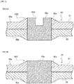
- the welded portion 63A formed by such a friction stir spot welding method is thicker than the entire workpiece 60, as schematically shown in the upper diagram of Fig. 4 .
- a stirred portion boundary 60e which is a boundary between the stirred portion 60c where the material is stirred and the non-stirred portion where the material is not stirred, is located in the thick region.
- a concave portion 60d derived from the pin member 11 is backfilled and shaped substantially flat without no thick region formed.
- the friction stir spot welding method (and the friction stir spot welding device 10A) according to the present disclosure, a simple configuration in which the inclined surface 13b is provided on the clamp member 13, as compared with the conventional friction stir spot welding method, can selectively increase the thickness at the welded portion 63A. Moreover, the material that increases the thickness is supplemented by forming the concave portion 60d in the center of the welded portion 63A by press-fitting the pin member 11. Therefore, the thickness of the welded portion 63A can be selectively increased without increasing the weight, so that the strength of the welded portion 63A can be improved.
- a comparative welded portion 72 as schematically shown in the lower diagram of Fig. 4 is formed.
- this comparative welded portion 72 is similar to the welded portion 63A shown in the upper diagram of Fig. 4 , but the stirred portion boundary 60e is not located at the thick region of the comparative welded portion 72 and is formed near the boundary between the comparative welded portion 72 and the portion that is not welded. As a result, the comparative welded portion 72 cannot sufficiently improve the strength even with the increased thickness.
- one end of the strip-like front-side workpiece 61 is stacked on one end of the strip-like back-side workpiece 62 to form the conventional welded portion 71, thereby forming the joint structure of the workpieces 61 and 62.
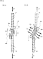
- the thickness of the welded portion 63A is large. Accordingly, because the rigidity of the welded portion 63A increases, as shown in Fig. 5A , even when a tensile load is applied in the direction of the arrow D1, it is possible to suppress the occurrence of bending around the welded portion 63A. Accordingly, a tensile shear load occurs near the welded portion 63A, as indicated by an arrow D0, and a peeling load is less likely to occur, as indicated by the arrow D3 in Fig. 5B . Therefore, it is possible to effectively suppress a reduction in the strength of the joint region.
- stirred portion boundary 60e is located at the thick region of the welded portion 63A, the strength of the stirred portion boundary 60e can be improved. Because the stirred portion boundary 60e is a region where stress is most concentrated in the load form described above, the relaxation of the stress acting on the stirred portion boundary 60e contributes to an improvement in strength as a joint.
- the tapered inclined surface 13b is formed inside the pressing surface 13a of the clamp member 13 that is a holding jig. Therefore, by aligning the contact surface 12a of the shoulder member 12 with the upper edge of the inclined surface 13b, the annular concave region S1 whose periphery is covered with the clamp member 13 can be formed at the distal end portions of the rotary tools. By moving the rotary tools forward and backward with respect to the workpiece 60, a material constituting the workpiece 60 can be filled into the entire annular concave region S1.
- the press-fitting of the shoulder member 12 stirs the material located immediately below the shoulder contact surface 12a, whereas the surrounding material adjacent to the shoulder contact surface 12a is not stirred but softens to some extent. Accordingly, not only the material stirred with the press-fitting of the shoulder member 12 but also the surrounding softened material can be filled into the annular concave region S1.
- a thick region having an increased thickness is formed in the welded portion 63A of the workpiece 60 and the boundary (stirred portion boundary 60e) between the portion where the material is stirred and the portion where the material is not stirred is located at the thick region. Therefore, the rigidity of the welded portion 63A can be improved, and the possibility of breakage at the stirred portion boundary 60e can be effectively suppressed. As a result, it is possible to further improve the strength of, for example, the joint portion of the workpiece 60.
- the thick region of the welded portion 63A is configured to increase the thickness of the workpiece 60 on the obverse surface 60a side.
- the thickness of the workpiece 60 on the reverse surface 60b side may be increased.
- a friction stir spot welding device 10B according to Embodiment 2 includes, as main components, a pin member 11 and a shoulder member 12 (rotary tools), a clamp member 13 (holding jig), a spring 14, a tool driving unit 15, and a backing member 16 (holding jig).
- the backing member 16 according to Embodiment 2 is provided with a supporting surface concave portion 16b as shown in Fig. 6 .
- the supporting surface concave portion 16b is a circular concave portion provided in the supporting surface 16a of the backing member 16.
- the peripheral edge portion of the supporting surface concave portion 16b is an inclined surface that inclines so as to reduce the diameter from the supporting surface 16a in the depth direction.
- the inclined surface of the peripheral edge portion of the supporting surface concave portion 16b is referred to as a "concave-portion peripheral-edge inclined surface" for convenience of distinguishing from the inclined surface 13b of the clamp member 13.
- the position where the supporting surface concave portion 16b is provided in the supporting surface 16a is not particularly limited, and may be a position where a thick region can be formed on the reverse surface 60b side of the welded portion of the workpiece 60.
- the supporting surface concave portion 16b is configured as a flat bottomed hole such that the diameter at the bottom surface is the smallest and the diameter at the opening on the supporting surface 16a side is the largest.
- the supporting surface concave portion 16b needs to be located such that the bottom surface of the supporting surface concave portion 16b coincides with the tool contact position R0 or such that the tool contact position R0 is completely included in the bottom surface.
- the center of the bottom surface (in other words, the center of the supporting surface concave portion 16b) preferably substantially coincides with an axis Xr (the chain line in the Fig. 6 ) of the rotary tools.
- the thick region of the welded portion of the workpiece 60 is formed by filling the supporting surface concave portion 16b with a material by moving the rotary tools (the pin member 11 and the shoulder member 12) forward and backward. Therefore, by keeping the center of the bottom surface coincident with the axis Xr, the supporting surface concave portion 16b can be entirely filled with a material.
- the size of the supporting surface concave portion 16b is not particularly limited, but the bottom surface needs to be as large as the tool contact position R0. Because the tool contact position R0 substantially corresponds to contact surfaces 11a and 12a of the rotary tools, the bottom surface of the supporting surface concave portion 16b needs to have approximately the same size as the pin contact surface 11a and the shoulder contact surface 12a. In other words, the bottom surface of the supporting surface concave portion 16b needs to have approximately the same as the diameter of the shoulder member 12. Therefore, the concave-portion peripheral-edge inclined surface of the supporting surface concave portion 16b is located outside the tool contact position R0. Accordingly, as will be described later, a gap region similar to the gap region S0 (see Fig. 2A ) in Embodiment 1 can be formed from the concave-portion peripheral-edge inclined surface and the outer peripheral surface of the shoulder member 12.
- the depth of the supporting surface concave portion 16b, the expanding width of the concave-portion peripheral-edge inclined surface, the inclination angle of the concave-portion peripheral-edge inclined surface, the width of the concave-portion peripheral-edge inclined surface, and the like are not particularly limited.
- these numerical values can be appropriately set in accordance with various conditions required for the welded portion formed on the workpiece 60, especially the thickness of the thick region formed on the reverse surface 60b.
- the concave-portion peripheral-edge inclined surface is not particularly limited as long as it is a surface inclined so as to reduce the diameter from the supporting surface 16a in the depth direction, as described above. Therefore, the concave-portion peripheral-edge inclined surface may be a flat surface (planar surface) as schematically shown in Fig. 6 or a curved surface, similar to the inclined surface 13b of the clamp member 13 described above. Further, the concave-portion peripheral-edge inclined surface may be configured by a single plane as shown in Fig. 6 , but may be configured by a plurality of planes adjacent to each other or a plurality of curved surfaces adjacent to each other, or may be configured to include both a flat surface and a curved surface.
- the friction stir spot welding device 10B according to Embodiment 2 has the same configuration as that of the friction stir spot welding device 10A according to Embodiment 1 except for the configuration of the backing member 16, and hence a description of the same configuration will be omitted.
- FIG. 7A to 7E A typical configuration of the friction stir spot welding method according to Embodiment 2 will be described in detail next with reference to Figs. 7A to 7E , Figs. 8A to 8E , and Figs. 9A and 9B with the above friction stir spot welding device 10B taken as an example.
- Figs. 7A to 7E or Figs. 8A to 8E like Figs. 3A to 3D referred to in Embodiment 1, for convenience of explaining the forward/backward movement of the rotary tools, the contact surfaces 11a and 12a of the rotary tools and the pressing surface 13a of the clamp member 13 are not denoted by reference numerals.
- Embodiment 2 unlike Embodiment 1, because the supporting surface concave portion 16b is also formed in the backing member 16, in the welded portion of the workpiece 60, not only an obverse surface 60a but also a reverse surface 60b increases in thickness. Therefore, in Embodiment 2, for example, as schematically shown in Fig. 7A , before the workpiece 60 is partially stirred, an additional material 64 of the same type as the workpiece 60 is provided at a region to be stirred. At the time of stirring with the rotary tools, not only the workpiece 60 but also the additional material 64 is stirred together to supplement the additional material 64 for an increase in the thickness of the reverse surface 60b.
- Embodiment 2 as in Embodiment 1 described above, as shown in Fig. 7A , while the reverse surface 60b of the workpiece 60 is supported by the backing member 16, the obverse surface 60a of the workpiece 60 is pressed by the pressing surface 13a of the clamp member 13. As a result, the workpiece 60 (the front-side workpiece 61 and the back-side workpiece 62) is sandwiched between the clamp member 13 and the backing member 16. At this time, in Embodiment 2, the additional material 64 is supplied to the supporting surface concave portion 16b.
- the additional material 64 is basically the same as the material constituting the workpiece 60, but may be a different material as long as it can be mixed with the material constituting the workpiece 60 by stirring with the rotary tools. By selecting a different material as the additional material 64, it becomes possible to impart characteristics that the workpiece 60 does not have (for example, high strength or high corrosion resistance) to the welded portion.
- the form of the additional material 64 is not particularly limited, and the additional material 64 may have a plate shape or block shape as schematically shown in Fig. 7A or other shapes, or may be a particulate, powdery, or other material. However, from the viewpoint of favorably supporting the reverse surface 60b of the workpiece 60 by the backing member 16, the additional material 64 is desirably in a form that can be accommodated in the supporting surface concave portion 16b (or a size that can be accommodated).
- the obverse surface 60a of the workpiece 60 is "preliminarily heated" with the rotary tools (the pin member 11 and the shoulder member 12) as in Embodiment 1 described above.
- the shoulder member 12 is made relatively protruded from the pin member 11 to further advance (press-fit) the shoulder member 12 into the obverse surface 60a.
- the stirred portion 60c is formed in not only the front-side workpiece 61 but also the back-side workpiece 62.
- the material of the stirred portion 60c is pushed away and flows from directly below the shoulder member 12 to directly below the pin member 11, so that the pin member 11 moves backward and rises as seen from the shoulder member 12. Further, the press-fitting of the shoulder member 12 causes the non-stirred softened material to be pushed outward at the portion around the stirred portion 60c. Therefore, as indicated by a broken line in Fig. 7B , a non-stirred softened material is filled into the gap region S0 generated between the outer peripheral surface of the shoulder member 12 and the inclined surface 13b.
- the shoulder member 12 is further press-fitted to reach the vicinity of the bottom surface of the supporting surface concave portion 16b.
- the additional material 64 is stirred, so that the softened additional material 64 is joined with the stirred portion 60c formed by stirring the workpiece 60.
- a gap region S3 which is a space region similar to the gap region S0, is formed between the concave-portion peripheral-edge inclined surface and the outer peripheral surface of the shoulder member 12, as indicated by a broken line in Fig. 7C .
- the non-stirred softened material is pushed outward at near the stirred portion 60c. Therefore, the gap region S3 is also filled with the non-stirred softened material.
- the shoulder member 12 that has been press-fitted is gradually retracted (pulled in).
- the shoulder member 12 present in the supporting surface concave portion 16b moves out of the supporting surface concave portion 16b, so that the supporting surface concave portion 16b is entirely filled with the material of the stirred portion 60c.
- the pin member 11 enters (is press-fitted into) the workpiece 60.
- the material of the stirred portion 60c is pushed away from immediately below the pin member 11 and flows toward the obverse surface 60a. Retracting the shoulder member 12 until the shoulder contact surface 12a is aligned with the upper edge of the inclined surface 13b fills the entire annular concave region S1 with the material, as indicated by a broken line in Fig. 7D .
- the pin member 11 is retracted (pulled in) to form a concave portion 60d in the stirred portion 60c derived from press-fit of the pin member 11.
- the material corresponding to the volume of the concave portion 60d fills the annular concave region S1 located on the obverse surface 60a.
- the supply of the additional material 64 also fills the supporting surface concave portion 16b located on the reverse surface 60b with the material.
- the additional material 64 is supplied only to the reverse surface 60b side, but an additional material 65 can also be supplied to the obverse surface 60a.
- the concave portion 60d derived from the pin member 11 can be backfilled and shaped substantially flat.
- the additional material 65 is supplied to a position on the obverse surface 60a of the workpiece 60 and immediately below the pin member 11.
- the additional material 64 is supplied to the supporting surface concave portion 16b of the backing member 16.
- the shoulder member 12 is advanced (press-fitted), and a non-stirred softened material is filled in the gap region S0 (see the region surrounded by the broken lines in Fig. 8B ) formed between the outer peripheral surface of the shoulder member 12 and the inclined surface 13b and the gap region S3 (see the region surrounded by the broken lines in Fig. 8C ) formed between the outer peripheral surface of the shoulder member 12 and the concave-portion peripheral-edge inclined surface, as in the state shown in Figs. 7B and 7C .
- the softened additional material 64 is joined in the stirred portion 60c.
- the press-fitted shoulder member 12 is gradually retracted to fill the entire supporting surface concave portion 16b with the material of the stirred portion 60c. Further, as the shoulder member 12 moves backward, the pin member 11 enters (is press-fitted into) the workpiece 60. At this time, the additional material 65 is stirred and softened by the pin member 11, and joined in the stirred portion 60c.
- a welded portion 63B or a welded portion 63C formed by the friction stir spot welding method as described above has thick regions with increased thicknesses on both the obverse surface 60a and the reverse surface 60b.
- the concave portion 60d derived from the pin member 11 remains in the welded portion 63B, but the concave portion 60d does not remain in the welded portion 63C, and the obverse surface 60a is shaped substantially flat.
- stirred portion boundary 60e which is the boundary between the stirred portion 60c where the material is stirred and the non-stirred portion where the material is not stirred is located at the thick region.
- the friction stir spot welding method (and the friction stir spot welding device 10B) according to the present disclosure, a simple configuration in which the inclined surface 13b is provided on the clamp member 13 and the supporting surface concave portion 16b is provided on the supporting surface 16a of the backing member 16 can selectively increase the thickness at the welded portion 63B or 63C.
- the reverse surface 60b side can be supplemented by the additional material 64
- the obverse surface 60a can be supplemented by the concave portion 60d formed in the center of the welded portion 63A by press-fitting the pin member 11 as in Embodiment 1 described above, and can be further supplemented by the additional material 65.
- the thickness can be selectively increased at the welded portion 63B or 63C, the increase in weight can be minimized even when the additional material 64 or 65 is supplied.
- the thickness increases on both the obverse surface 60a and the reverse surface 60b, even when a bending load is applied to the welded portion 63B or 63C upon application of the welded portion 63B or 63C to the welding of the joint structure, the strength reduction can be effectively suppressed.
- the stirred portion boundary 60e is located at the thick region at either the welded portion 63B or 63C, the strength of the stirred portion boundary 60e is improved, and the breakage at this region can be effectively suppressed.
- the additional material 64 or 65 is supplied before the workpiece 60 is stirred by the rotary tools.
- the additional material 64 or 65 may be supplied after the workpiece 60 is welded.
- the additional material 65 may be supplied to the obverse surface 60a in order to backfill the concave portion 60d, and welding may be performed again by the rotary tools.
- the additional material 64 may be supplied to the reverse surface 60b and the workpiece 60 may be welded again by the rotary tools.
- the additional material 64 or 65 may be supplied to the region to be stirred in the workpiece 60 (supplied before welding) or supplied to the welded portion 63A, 63B, or 63C formed on the workpiece 60 (supplied after welding).
- the additional material 64 is supplied to the reverse surface 60b, depending on various conditions, it is preferable to supply the material to the supporting surface concave portion 16b before welding as described in Embodiment 2.
- the additional material 64 is made to exist in the supporting surface concave portion 16b, so that the possibility that the workpiece 60 bends during press-fitting of the rotary tools can be prevented or suppressed.
- the additional material 64 is stirred by the shoulder member 12.
- the additional material 65 is stirred by the pin member 11.
- the method of stirring the additional material 64 or 65 is not limited to this, and the stirring may be performed by at least one of the pin member 11 and the shoulder member 12.
- the method of supplying the additional material 64 or 65 is not particularly limited.
- the additional material 64 or 65 may be supplied so as to come into contact with at least the obverse surface 60a or the reverse surface 60b of the workpiece 60.
- the concave portion 60d derived from the pin member 11 remains in both the welded portion 63A in Embodiment 1 and the welded portion 63B in Embodiment 2.
- the concave portion 60d basically does not affect the strength of the welded portion 63A. Therefore, it is not essential to backfill the concave portion 60d by supplying the additional material 65. Depending on the use of the workpiece 60, it may be better that the concave portion 60d does not exist. In such a case, the concave portion 60d is backfilled to shape the obverse surface 60a into a substantially flat shape like the welded portion 63C.
- the present disclosure is described with the friction stir spot welding device 10A or 10B using the clamp member 13 having the inclined surface 13b on the pressing surface 13a taken as an example.
- the present disclosure is not limited to the friction stir spot welding device 10A or 10B or the friction stir spot welding method using them.
- the clamp member 13 may be detachably mounted on the friction stir spot welding device 10A (or the friction stir spot welding device 10B).
- the clamp member 13 is a holding jig for holding the workpiece 60. Therefore, the present disclosure also includes the clamp member 13 having the inclined surface 13b, that is, a friction stir spot welding holding jig.
- the backing member 16 may be detachably mounted on the friction stir spot welding device 10A (or the friction stir spot welding device 10B).
- the backing member 16 is a holding jig that holds the workpiece 60. Therefore, the present disclosure also includes a friction stir spot welding holding jig set including the clamp member 13 as a first holding jig and the backing member 16 as a second holding jig.
- the backing member 16 may have the configuration described in Embodiment 1, but the backing member 16 having the supporting surface concave portion 16b described in Embodiment 2 is more preferable.
- a holding jig for double-acting friction stir spot welding may be a holding jig which is used for a friction stir spot welding device for welding a workpiece by partially stirring the workpiece with rotary tools and is configured to hold the workpiece.
- the friction stir spot welding device may include, as the rotary tools, a cylindrical pin member that is configured to rotate around an axis and be movable forward and backward along the axis and a cylindrical shoulder member that is positioned so as to surround an outside of the pin member and is configured to rotate around the axis of the pin member and be movable forward and backward along the axis.
- the holding jig may be a clamp member that has a cylindrical shape positioned so as to surround an outside of the shoulder member and is configured to press the workpiece from an obverse surface with an annular pressing surface of a distal end of the clamp member.
- the clamp member may have an inclined surface that is adjacent to an inner edge portion of the pressing surface and inclined so as to reduce an inner diameter of the clamp member toward a back side as viewed from the pressing surface.
- a tapered inclined surface is formed inside the pressing surface of the clamp member, and a concave region whose periphery is covered with the clamp member is formed on the distal end portions of the rotary tools by aligning the contact surface of the shoulder member with the upper edge of the inclined surface.
- the press-fitting of the shoulder member stirs the material located immediately below the contact surface of the shoulder member, whereas the surrounding material adjacent to the contact surface of the shoulder member is not stirred but softened to some extent. Accordingly, not only the material stirred with the press-fitting of the shoulder member but also the surrounding softened material can be filled into the concave region.
- stirred portion boundary is a stress concentration portion and is a region that tends to be a starting point of fracture. Therefore, the acting stress can be relieved and the rigidity of the welded portion can be improved. As a result, it is possible to further improve the strength of, for example, the joint portion of the workpiece.
- the inclined surface may be formed of at least one of a flat surface and a curved surface.
- a holding jig set for double-acting friction stir spot welding may be a holding jig set used for the double-acting friction stir spot welding device and configured to hold the workpiece.
- the holding jig set may include a holding jig for a double-acting friction stir spot welding device having the above configuration and a backing member that is positioned on an advancing direction side of the rotary tools and supports a reverse surface of the workpiece on a supporting surface with an obverse surface of the workpiece facing the rotary tools.
- a circular concave portion having a peripheral edge portion that is an inclined surface inclined so as to reduce a diameter from the supporting surface toward a depth direction may be formed in the supporting surface of the backing member.
- a concave region can be formed in the obverse surface side of a workpiece with the clamp member and the rotary tools
- a concave region can also be formed in the reverse surface side of the workpiece by the concave portion in the supporting surface of the backing member.
- the inclined surface may be formed of at least one of a flat surface and a curved surface.
- a double-acting friction stir spot welding device may include the holding jig for double-acting friction stir spot welding which has the above configuration or the holding jig set for double-acting friction stir spot welding which has the above configuration.
- a double-acting friction stir spot welding method may be a double-acting friction stir spot welding method of welding a workpiece held by a holding jig by partially stirring the workpiece with rotary tools.
- a cylindrical pin member that is configured to rotate around an axis and be movable forward and backward along the axis and a cylindrical shoulder member that is positioned so as to surround an outside of the pin member and is configured to rotate around the axis of the pin member and be movable forward and backward along the axis may be used as the rotary tools in a forward/backward movable state.
- a clamp member that has a cylindrical shape positioned so as to surround an outside of the shoulder member and is configured to press the workpiece from an obverse surface with an annular pressing surface of a distal end of the clamp member may be used as the holding jig.
- the clamp member may have an inclined surface that is adjacent to an inner edge portion of the pressing surface and inclined so as to reduce an inner diameter of the clamp member toward a back side as viewed from the pressing surface.
- the method may include aligning a contact surface of the shoulder member with an upper edge of the inclined surface of the clamp member to form a concave region by at least the inclined surface and the contact surface, and filling the concave region with a material constituting the workpiece.
- the concave region may be formed by advancing and retracting the shoulder member, and the pin member may be press-fitted into a stirred portion of the material which is formed by partially stirring the workpiece with the rotary tools, thereby filling the concave region with the material of the stirred portion.
- an additional material that is allowed to be stirred and mixed with the material constituting the workpiece may be supplied to a region of the workpiece which is to be stirred or a welded portion formed on the workpiece, the concave region may be formed after the workpiece is stirred together with the additional material with at least one of the pin member and the shoulder member, and the concave region may be filled with the material.
- a backing member that is positioned on an advancing direction side of the rotary tools and supports a reverse surface of the workpiece on a supporting surface with the obverse surface of the workpiece facing the rotary tools may also be used as the holding jig, a circular concave portion having a peripheral edge portion that is an inclined surface inclined so as to reduce the diameter from the supporting surface toward a depth direction may be formed in the supporting surface of the backing member, and both the concave region and the concave portion may be filled with the material.
- the additional material may be supplied so as to come into contact with at least one of the obverse surface and the reverse surface of the workpiece.
- a concave region is formed at least on the obverse surface of the workpiece (or both the obverse and reverse surfaces), and the material can be filled in the concave region by moving the rotary tools back and forth. Therefore, a thick region where the stirred portion boundary is located can be formed on at least the obverse surface (or both the obverse and reverse surfaces) of the welded portion of the workpiece.
- the material for forming the thick region may be supplemented with a material that has been pushed away by press-fitting the pin member, or may be supplemented by supplying an additional material.
- the double-acting friction stir spot welding method having the above configuration, because the welded portion of the workpiece can be selectively thickened, using a material pushed away by the pin member makes it possible to form a thick welded portion without increasing the weight, whereas supplying an additional material makes it possible to suppress an increase in weight to a necessary minimum level when forming a thick welded portion.
- a concave portion derived from the rotary tools can be backfilled to form the welded portion into a substantially flat shape.
- At least one of the inclined surface provided on the clamp member and the inclined surface provided on the supporting surface of the backing member is formed from at least one of a flat surface and a curved surface.
- the present invention can improve the strength of a welded portion in double-acting friction stir spot welding, and hence can be widely used in various fields using double-acting friction stir spot welding.
Landscapes
- Engineering & Computer Science (AREA)
- Mechanical Engineering (AREA)
- Pressure Welding/Diffusion-Bonding (AREA)
Applications Claiming Priority (2)
| Application Number | Priority Date | Filing Date | Title |
|---|---|---|---|
| JP2017172966A JP6796042B2 (ja) | 2017-09-08 | 2017-09-08 | 複動式摩擦攪拌点接合用保持治具および保持治具セット、並びに、複動式摩擦攪拌点接合装置および複動式摩擦攪拌点接合方法 |
| PCT/JP2018/033255 WO2019050002A1 (ja) | 2017-09-08 | 2018-09-07 | 複動式摩擦攪拌点接合用保持治具および保持治具セット、並びに、複動式摩擦攪拌点接合装置および複動式摩擦攪拌点接合方法 |
Publications (3)
| Publication Number | Publication Date |
|---|---|
| EP3680055A1 true EP3680055A1 (de) | 2020-07-15 |
| EP3680055A4 EP3680055A4 (de) | 2021-01-13 |
| EP3680055B1 EP3680055B1 (de) | 2022-12-21 |
Family
ID=65633942
Family Applications (1)
| Application Number | Title | Priority Date | Filing Date |
|---|---|---|---|
| EP18854125.4A Active EP3680055B1 (de) | 2017-09-08 | 2018-09-07 | Vorrichtung für doppelwirkungs-reibrührpunktschweissverfahren und verfahren für doppelwirkungs-reibrührpunktschweissverfahren |
Country Status (4)
| Country | Link |
|---|---|
| US (2) | US11396060B2 (de) |
| EP (1) | EP3680055B1 (de) |
| JP (1) | JP6796042B2 (de) |
| WO (1) | WO2019050002A1 (de) |
Cited By (1)
| Publication number | Priority date | Publication date | Assignee | Title |
|---|---|---|---|---|
| EP4197681A4 (de) * | 2020-09-11 | 2024-04-10 | Kawasaki Jukogyo Kabushiki Kaisha | Reibrührpunktschweissverfahren und geschweisster körper damit |
Families Citing this family (11)
| Publication number | Priority date | Publication date | Assignee | Title |
|---|---|---|---|---|
| JP6796565B2 (ja) * | 2017-09-08 | 2020-12-09 | 川崎重工業株式会社 | 複動式摩擦攪拌点接合方法 |
| JP7181113B2 (ja) * | 2019-02-08 | 2022-11-30 | トヨタ自動車株式会社 | 異種金属接合方法 |
| EP3744467A1 (de) * | 2019-05-27 | 2020-12-02 | Harms & Wende GmbH & Co. KG | Vorrichtung zum reibpunktschweissen |
| CN115943008B (zh) * | 2020-05-29 | 2025-12-02 | 川崎重工业株式会社 | 摩擦搅拌点接合装置以及接缝构造 |
| JP7596088B2 (ja) * | 2020-07-09 | 2024-12-09 | 株式会社Uacj | 摩擦攪拌点接合装置及び摩擦攪拌点接合方法 |
| CN112108754A (zh) * | 2020-08-06 | 2020-12-22 | 山东碳垣纳米科技有限公司 | 搅拌头、点焊机头以及回抽点焊设备 |
| JP7487651B2 (ja) * | 2020-12-04 | 2024-05-21 | 日本軽金属株式会社 | 回転ツール、接合装置および接合方法 |
| DE102021119907A1 (de) | 2021-07-30 | 2023-02-02 | Volkswagen Aktiengesellschaft | Rührreibschweißvorrichtung, Verfahren zur Herstellung einer Baugruppe mit einer Rührreibschweißvorrichtung sowie eine Baugruppe |
| EP4360796A4 (de) * | 2021-08-31 | 2024-10-16 | JFE Steel Corporation | Reibrührpunktgeschweisste verbindung, herstellungsverfahren dafür und reibrührpunktschweissverfahren |
| JP2023152110A (ja) * | 2022-04-01 | 2023-10-16 | 川崎重工業株式会社 | 摩擦撹拌接合装置及びそのメンテナンス方法 |
| CN119426780B (zh) * | 2024-10-11 | 2025-09-16 | 安徽万宇机械设备科技有限公司 | 送丝增材装置和基材加工设备 |
Family Cites Families (21)
| Publication number | Priority date | Publication date | Assignee | Title |
|---|---|---|---|---|
| US5617652A (en) * | 1980-02-02 | 1997-04-08 | Multifastener Corporation | Fastener installation and method |
| US5174018A (en) * | 1981-01-28 | 1992-12-29 | Multifastener Corporation | Die button with staking features |
| JP3205362B2 (ja) | 1991-11-01 | 2001-09-04 | ワイケイケイ株式会社 | 高強度高靭性アルミニウム基合金 |
| JPH0957455A (ja) * | 1995-08-21 | 1997-03-04 | Suzuki Motor Corp | スポット溶接用裏当材 |
| US5697544A (en) * | 1996-03-21 | 1997-12-16 | Boeing North American, Inc. | Adjustable pin for friction stir welding tool |
| JP4159297B2 (ja) * | 2002-03-07 | 2008-10-01 | 川崎重工業株式会社 | スポット接合システム |
| JP4321017B2 (ja) * | 2002-07-26 | 2009-08-26 | トヨタ自動車株式会社 | 摩擦撹拌接合方法及び摩擦撹拌接合用回転ツール |
| JP4450728B2 (ja) * | 2003-12-22 | 2010-04-14 | 株式会社神戸製鋼所 | 摩擦撹拌接合方法 |
| JP2006000858A (ja) * | 2004-06-15 | 2006-01-05 | Honda Motor Co Ltd | 摩擦撹拌接合方法及びその装置 |
| JP4516410B2 (ja) * | 2004-11-10 | 2010-08-04 | 本田技研工業株式会社 | 積層体の接合方法 |
| US7581665B2 (en) * | 2006-01-04 | 2009-09-01 | The Boeing Company | Methods and apparatus for retractable pin friction stir welding and spot welding |
| US7699206B2 (en) * | 2008-04-07 | 2010-04-20 | The Boeing Company | Gimballing roller device for friction stir welding apparatus and method |
| CA2733025C (en) * | 2008-08-11 | 2015-12-29 | Megastir Technologies Llc | Rotary holding device for gripping tool material at elevated temperatures through multiple collar assembly |
| JP5685461B2 (ja) * | 2011-03-18 | 2015-03-18 | 川崎重工業株式会社 | 摩擦攪拌点接合を用いた孔補修方法 |
| JP5588385B2 (ja) | 2011-03-18 | 2014-09-10 | 川崎重工業株式会社 | 摩擦攪拌点接合装置および摩擦攪拌点接合方法 |
| JP5815961B2 (ja) | 2011-03-18 | 2015-11-17 | 川崎重工業株式会社 | 摩擦攪拌点接合装置および摩擦攪拌点接合方法 |
| EP2596898B1 (de) * | 2011-11-25 | 2014-10-01 | Helmholtz-Zentrum Geesthacht Zentrum für Material- und Küstenforschung GmbH | Selbstspannendes Reibschweißwerkzeug |
| US9199756B2 (en) | 2011-11-28 | 2015-12-01 | Avery Dennison Corporation | Fastener stock and device for use in dispensing plastic fasteners therefrom |
| US10201873B2 (en) * | 2014-10-23 | 2019-02-12 | Kawasaki Jukogyo Kabushiki Kaisha | Friction stir spot welding device and friction stir spot welding method |
| US10293431B2 (en) * | 2014-12-15 | 2019-05-21 | Kawasaki Jukogyo Kabushiki Kaisha | Friction stir spot welding apparatus and friction stir spot welding method |
| WO2016186134A1 (ja) * | 2015-05-18 | 2016-11-24 | 株式会社Ihi | 摩擦攪拌接合装置および摩擦攪拌接合方法 |
-
2017
- 2017-09-08 JP JP2017172966A patent/JP6796042B2/ja active Active
-
2018
- 2018-09-07 WO PCT/JP2018/033255 patent/WO2019050002A1/ja not_active Ceased
- 2018-09-07 EP EP18854125.4A patent/EP3680055B1/de active Active
-
2020
- 2020-03-06 US US16/810,856 patent/US11396060B2/en active Active
-
2022
- 2022-06-17 US US17/842,813 patent/US12059742B2/en active Active
Cited By (1)
| Publication number | Priority date | Publication date | Assignee | Title |
|---|---|---|---|---|
| EP4197681A4 (de) * | 2020-09-11 | 2024-04-10 | Kawasaki Jukogyo Kabushiki Kaisha | Reibrührpunktschweissverfahren und geschweisster körper damit |
Also Published As
| Publication number | Publication date |
|---|---|
| JP6796042B2 (ja) | 2020-12-02 |
| JP2019048305A (ja) | 2019-03-28 |
| EP3680055B1 (de) | 2022-12-21 |
| US12059742B2 (en) | 2024-08-13 |
| US20220324052A1 (en) | 2022-10-13 |
| US11396060B2 (en) | 2022-07-26 |
| EP3680055A4 (de) | 2021-01-13 |
| WO2019050002A1 (ja) | 2019-03-14 |
| US20200206838A1 (en) | 2020-07-02 |
Similar Documents
| Publication | Publication Date | Title |
|---|---|---|
| EP3680055B1 (de) | Vorrichtung für doppelwirkungs-reibrührpunktschweissverfahren und verfahren für doppelwirkungs-reibrührpunktschweissverfahren | |
| CN103521911B (zh) | 金属材料用搅拌摩擦焊方法及由此获得的金属材料焊接体 | |
| EP2474382A1 (de) | Beidseitiges rührreibschweissverfahren, verbindungsvorrichtung verbindungsverfahren für eine metallplatte in einer kaltwalzanlage und kaltwalzanlage | |
| JP6796565B2 (ja) | 複動式摩擦攪拌点接合方法 | |
| EP3260230A1 (de) | Verbindungsverfahren und verfahren zur herstellung eines verbundstoffwalzmaterials | |
| EP2361708B1 (de) | Einwegdrehwerkzeug | |
| CN103052462B (zh) | 摩擦搅拌接合系统以及摩擦搅拌接合方法 | |
| EP3680053A1 (de) | Verfahren zum reibrührschweissen mit doppelter wirkung, presswerkzeugsatz und vorrichtung zum reibrührschweissen mit doppelter wirkung | |
| EP2316604B1 (de) | Reibrührschweißvorrichtung für Überlappstoss | |
| BR112012012017B1 (pt) | Method and welding apparatus for two-side shaking and attraction, and, two-side shaking and twilight attachment tools assembly | |
| JP2004058135A (ja) | 接合方法及び接合ツール | |
| KR101799218B1 (ko) | 마찰 교반 접합 방법 | |
| EP3868506A1 (de) | Schweissverfahren zum verbinden von unterschiedlichen materialien, verbindungshilfselement und schweissverbindung mit unterschiedlichen materialien | |
| JP2012170967A (ja) | 異種金属板の接合方法及び異種金属板の接合構造 | |
| CN101104186A (zh) | 铆接冲头与具备铆接冲头的铆接装置 | |
| JP4986532B2 (ja) | 摩擦撹拌接合方法 | |
| CN211219149U (zh) | 一种静轴肩倾斜的搅拌摩擦焊接工具及搅拌摩擦焊接设备 | |
| JP6300077B2 (ja) | 摩擦撹拌接合方法および摩擦撹拌接合体 | |
| JP2013169567A (ja) | 自己穿孔型リベット用ダイ | |
| JP2000127248A (ja) | 超音波接合方法 | |
| JP2018020359A (ja) | 異種材接合方法 | |
| JP2012192437A (ja) | 摩擦撹拌接合工具 | |
| CN110948105B (zh) | 一种静轴肩倾斜的搅拌摩擦焊接工具及搅拌摩擦焊接方法 | |
| JP2016083669A (ja) | エッジディスタンスを減少させる摩擦攪拌点接合装置および摩擦攪拌点接合方法 | |
| JP2005076415A (ja) | 鋼管杭、及びそれを用いた鋼管杭の接続方法 |
Legal Events
| Date | Code | Title | Description |
|---|---|---|---|
| STAA | Information on the status of an ep patent application or granted ep patent |
Free format text: STATUS: THE INTERNATIONAL PUBLICATION HAS BEEN MADE |
|
| PUAI | Public reference made under article 153(3) epc to a published international application that has entered the european phase |
Free format text: ORIGINAL CODE: 0009012 |
|
| STAA | Information on the status of an ep patent application or granted ep patent |
Free format text: STATUS: REQUEST FOR EXAMINATION WAS MADE |
|
| 17P | Request for examination filed |
Effective date: 20200310 |
|
| AK | Designated contracting states |
Kind code of ref document: A1 Designated state(s): AL AT BE BG CH CY CZ DE DK EE ES FI FR GB GR HR HU IE IS IT LI LT LU LV MC MK MT NL NO PL PT RO RS SE SI SK SM TR |
|
| AX | Request for extension of the european patent |
Extension state: BA ME |
|
| DAV | Request for validation of the european patent (deleted) | ||
| DAX | Request for extension of the european patent (deleted) | ||
| A4 | Supplementary search report drawn up and despatched |
Effective date: 20201211 |
|
| RIC1 | Information provided on ipc code assigned before grant |
Ipc: B23K 20/12 20060101AFI20201207BHEP |
|
| STAA | Information on the status of an ep patent application or granted ep patent |
Free format text: STATUS: EXAMINATION IS IN PROGRESS |
|
| 17Q | First examination report despatched |
Effective date: 20211012 |
|
| GRAP | Despatch of communication of intention to grant a patent |
Free format text: ORIGINAL CODE: EPIDOSNIGR1 |
|
| STAA | Information on the status of an ep patent application or granted ep patent |
Free format text: STATUS: GRANT OF PATENT IS INTENDED |
|
| GRAS | Grant fee paid |
Free format text: ORIGINAL CODE: EPIDOSNIGR3 |
|
| INTG | Intention to grant announced |
Effective date: 20221018 |
|
| RIN1 | Information on inventor provided before grant (corrected) |
Inventor name: YAMADA, ETSUKO Inventor name: HIRANO, MASAAKI |
|
| GRAA | (expected) grant |
Free format text: ORIGINAL CODE: 0009210 |
|
| STAA | Information on the status of an ep patent application or granted ep patent |
Free format text: STATUS: THE PATENT HAS BEEN GRANTED |
|
| AK | Designated contracting states |
Kind code of ref document: B1 Designated state(s): AL AT BE BG CH CY CZ DE DK EE ES FI FR GB GR HR HU IE IS IT LI LT LU LV MC MK MT NL NO PL PT RO RS SE SI SK SM TR |
|
| REG | Reference to a national code |
Ref country code: GB Ref legal event code: FG4D |
|
| REG | Reference to a national code |
Ref country code: CH Ref legal event code: EP |
|
| REG | Reference to a national code |
Ref country code: DE Ref legal event code: R096 Ref document number: 602018044586 Country of ref document: DE |
|
| REG | Reference to a national code |
Ref country code: AT Ref legal event code: REF Ref document number: 1538749 Country of ref document: AT Kind code of ref document: T Effective date: 20230115 |
|
| REG | Reference to a national code |
Ref country code: IE Ref legal event code: FG4D |
|
| REG | Reference to a national code |
Ref country code: LT Ref legal event code: MG9D |
|
| REG | Reference to a national code |
Ref country code: NL Ref legal event code: MP Effective date: 20221221 |
|
| PG25 | Lapsed in a contracting state [announced via postgrant information from national office to epo] |
Ref country code: SE Free format text: LAPSE BECAUSE OF FAILURE TO SUBMIT A TRANSLATION OF THE DESCRIPTION OR TO PAY THE FEE WITHIN THE PRESCRIBED TIME-LIMIT Effective date: 20221221 Ref country code: NO Free format text: LAPSE BECAUSE OF FAILURE TO SUBMIT A TRANSLATION OF THE DESCRIPTION OR TO PAY THE FEE WITHIN THE PRESCRIBED TIME-LIMIT Effective date: 20230321 Ref country code: LT Free format text: LAPSE BECAUSE OF FAILURE TO SUBMIT A TRANSLATION OF THE DESCRIPTION OR TO PAY THE FEE WITHIN THE PRESCRIBED TIME-LIMIT Effective date: 20221221 Ref country code: FI Free format text: LAPSE BECAUSE OF FAILURE TO SUBMIT A TRANSLATION OF THE DESCRIPTION OR TO PAY THE FEE WITHIN THE PRESCRIBED TIME-LIMIT Effective date: 20221221 |
|
| REG | Reference to a national code |
Ref country code: AT Ref legal event code: MK05 Ref document number: 1538749 Country of ref document: AT Kind code of ref document: T Effective date: 20221221 |
|
| PG25 | Lapsed in a contracting state [announced via postgrant information from national office to epo] |
Ref country code: RS Free format text: LAPSE BECAUSE OF FAILURE TO SUBMIT A TRANSLATION OF THE DESCRIPTION OR TO PAY THE FEE WITHIN THE PRESCRIBED TIME-LIMIT Effective date: 20221221 Ref country code: LV Free format text: LAPSE BECAUSE OF FAILURE TO SUBMIT A TRANSLATION OF THE DESCRIPTION OR TO PAY THE FEE WITHIN THE PRESCRIBED TIME-LIMIT Effective date: 20221221 Ref country code: HR Free format text: LAPSE BECAUSE OF FAILURE TO SUBMIT A TRANSLATION OF THE DESCRIPTION OR TO PAY THE FEE WITHIN THE PRESCRIBED TIME-LIMIT Effective date: 20221221 Ref country code: GR Free format text: LAPSE BECAUSE OF FAILURE TO SUBMIT A TRANSLATION OF THE DESCRIPTION OR TO PAY THE FEE WITHIN THE PRESCRIBED TIME-LIMIT Effective date: 20230322 |
|
| PG25 | Lapsed in a contracting state [announced via postgrant information from national office to epo] |
Ref country code: NL Free format text: LAPSE BECAUSE OF FAILURE TO SUBMIT A TRANSLATION OF THE DESCRIPTION OR TO PAY THE FEE WITHIN THE PRESCRIBED TIME-LIMIT Effective date: 20221221 |
|
| PG25 | Lapsed in a contracting state [announced via postgrant information from national office to epo] |
Ref country code: SM Free format text: LAPSE BECAUSE OF FAILURE TO SUBMIT A TRANSLATION OF THE DESCRIPTION OR TO PAY THE FEE WITHIN THE PRESCRIBED TIME-LIMIT Effective date: 20221221 Ref country code: RO Free format text: LAPSE BECAUSE OF FAILURE TO SUBMIT A TRANSLATION OF THE DESCRIPTION OR TO PAY THE FEE WITHIN THE PRESCRIBED TIME-LIMIT Effective date: 20221221 Ref country code: PT Free format text: LAPSE BECAUSE OF FAILURE TO SUBMIT A TRANSLATION OF THE DESCRIPTION OR TO PAY THE FEE WITHIN THE PRESCRIBED TIME-LIMIT Effective date: 20230421 Ref country code: ES Free format text: LAPSE BECAUSE OF FAILURE TO SUBMIT A TRANSLATION OF THE DESCRIPTION OR TO PAY THE FEE WITHIN THE PRESCRIBED TIME-LIMIT Effective date: 20221221 Ref country code: EE Free format text: LAPSE BECAUSE OF FAILURE TO SUBMIT A TRANSLATION OF THE DESCRIPTION OR TO PAY THE FEE WITHIN THE PRESCRIBED TIME-LIMIT Effective date: 20221221 Ref country code: CZ Free format text: LAPSE BECAUSE OF FAILURE TO SUBMIT A TRANSLATION OF THE DESCRIPTION OR TO PAY THE FEE WITHIN THE PRESCRIBED TIME-LIMIT Effective date: 20221221 Ref country code: AT Free format text: LAPSE BECAUSE OF FAILURE TO SUBMIT A TRANSLATION OF THE DESCRIPTION OR TO PAY THE FEE WITHIN THE PRESCRIBED TIME-LIMIT Effective date: 20221221 |
|
| PG25 | Lapsed in a contracting state [announced via postgrant information from national office to epo] |
Ref country code: SK Free format text: LAPSE BECAUSE OF FAILURE TO SUBMIT A TRANSLATION OF THE DESCRIPTION OR TO PAY THE FEE WITHIN THE PRESCRIBED TIME-LIMIT Effective date: 20221221 Ref country code: PL Free format text: LAPSE BECAUSE OF FAILURE TO SUBMIT A TRANSLATION OF THE DESCRIPTION OR TO PAY THE FEE WITHIN THE PRESCRIBED TIME-LIMIT Effective date: 20221221 Ref country code: IS Free format text: LAPSE BECAUSE OF FAILURE TO SUBMIT A TRANSLATION OF THE DESCRIPTION OR TO PAY THE FEE WITHIN THE PRESCRIBED TIME-LIMIT Effective date: 20230421 Ref country code: AL Free format text: LAPSE BECAUSE OF FAILURE TO SUBMIT A TRANSLATION OF THE DESCRIPTION OR TO PAY THE FEE WITHIN THE PRESCRIBED TIME-LIMIT Effective date: 20221221 |
|
| REG | Reference to a national code |
Ref country code: DE Ref legal event code: R097 Ref document number: 602018044586 Country of ref document: DE |
|
| PLBE | No opposition filed within time limit |
Free format text: ORIGINAL CODE: 0009261 |
|
| STAA | Information on the status of an ep patent application or granted ep patent |
Free format text: STATUS: NO OPPOSITION FILED WITHIN TIME LIMIT |
|
| PG25 | Lapsed in a contracting state [announced via postgrant information from national office to epo] |
Ref country code: DK Free format text: LAPSE BECAUSE OF FAILURE TO SUBMIT A TRANSLATION OF THE DESCRIPTION OR TO PAY THE FEE WITHIN THE PRESCRIBED TIME-LIMIT Effective date: 20221221 |
|
| 26N | No opposition filed |
Effective date: 20230922 |
|
| PG25 | Lapsed in a contracting state [announced via postgrant information from national office to epo] |
Ref country code: SI Free format text: LAPSE BECAUSE OF FAILURE TO SUBMIT A TRANSLATION OF THE DESCRIPTION OR TO PAY THE FEE WITHIN THE PRESCRIBED TIME-LIMIT Effective date: 20221221 |
|
| REG | Reference to a national code |
Ref country code: CH Ref legal event code: PL |
|
| PG25 | Lapsed in a contracting state [announced via postgrant information from national office to epo] |
Ref country code: LU Free format text: LAPSE BECAUSE OF NON-PAYMENT OF DUE FEES Effective date: 20230907 |
|
| REG | Reference to a national code |
Ref country code: BE Ref legal event code: MM Effective date: 20230930 |
|
| GBPC | Gb: european patent ceased through non-payment of renewal fee |
Effective date: 20230907 |
|
| PG25 | Lapsed in a contracting state [announced via postgrant information from national office to epo] |
Ref country code: LU Free format text: LAPSE BECAUSE OF NON-PAYMENT OF DUE FEES Effective date: 20230907 Ref country code: MC Free format text: LAPSE BECAUSE OF FAILURE TO SUBMIT A TRANSLATION OF THE DESCRIPTION OR TO PAY THE FEE WITHIN THE PRESCRIBED TIME-LIMIT Effective date: 20221221 |
|
| REG | Reference to a national code |
Ref country code: IE Ref legal event code: MM4A |
|
| PG25 | Lapsed in a contracting state [announced via postgrant information from national office to epo] |
Ref country code: IE Free format text: LAPSE BECAUSE OF NON-PAYMENT OF DUE FEES Effective date: 20230907 |
|
| PG25 | Lapsed in a contracting state [announced via postgrant information from national office to epo] |
Ref country code: GB Free format text: LAPSE BECAUSE OF NON-PAYMENT OF DUE FEES Effective date: 20230907 |
|
| PG25 | Lapsed in a contracting state [announced via postgrant information from national office to epo] |
Ref country code: CH Free format text: LAPSE BECAUSE OF NON-PAYMENT OF DUE FEES Effective date: 20230930 |
|
| PG25 | Lapsed in a contracting state [announced via postgrant information from national office to epo] |
Ref country code: IE Free format text: LAPSE BECAUSE OF NON-PAYMENT OF DUE FEES Effective date: 20230907 Ref country code: GB Free format text: LAPSE BECAUSE OF NON-PAYMENT OF DUE FEES Effective date: 20230907 Ref country code: CH Free format text: LAPSE BECAUSE OF NON-PAYMENT OF DUE FEES Effective date: 20230930 |
|
| PG25 | Lapsed in a contracting state [announced via postgrant information from national office to epo] |
Ref country code: BE Free format text: LAPSE BECAUSE OF NON-PAYMENT OF DUE FEES Effective date: 20230930 |
|
| PG25 | Lapsed in a contracting state [announced via postgrant information from national office to epo] |
Ref country code: BG Free format text: LAPSE BECAUSE OF FAILURE TO SUBMIT A TRANSLATION OF THE DESCRIPTION OR TO PAY THE FEE WITHIN THE PRESCRIBED TIME-LIMIT Effective date: 20221221 |
|
| PG25 | Lapsed in a contracting state [announced via postgrant information from national office to epo] |
Ref country code: BG Free format text: LAPSE BECAUSE OF FAILURE TO SUBMIT A TRANSLATION OF THE DESCRIPTION OR TO PAY THE FEE WITHIN THE PRESCRIBED TIME-LIMIT Effective date: 20221221 |
|
| PG25 | Lapsed in a contracting state [announced via postgrant information from national office to epo] |
Ref country code: IT Free format text: LAPSE BECAUSE OF NON-PAYMENT OF DUE FEES Effective date: 20230907 |
|
| PG25 | Lapsed in a contracting state [announced via postgrant information from national office to epo] |
Ref country code: IT Free format text: LAPSE BECAUSE OF NON-PAYMENT OF DUE FEES Effective date: 20230907 |
|
| PG25 | Lapsed in a contracting state [announced via postgrant information from national office to epo] |
Ref country code: CY Free format text: LAPSE BECAUSE OF FAILURE TO SUBMIT A TRANSLATION OF THE DESCRIPTION OR TO PAY THE FEE WITHIN THE PRESCRIBED TIME-LIMIT; INVALID AB INITIO Effective date: 20180907 |
|
| PG25 | Lapsed in a contracting state [announced via postgrant information from national office to epo] |
Ref country code: HU Free format text: LAPSE BECAUSE OF FAILURE TO SUBMIT A TRANSLATION OF THE DESCRIPTION OR TO PAY THE FEE WITHIN THE PRESCRIBED TIME-LIMIT; INVALID AB INITIO Effective date: 20180907 |
|
| PGFP | Annual fee paid to national office [announced via postgrant information from national office to epo] |
Ref country code: DE Payment date: 20250730 Year of fee payment: 8 |
|
| PGFP | Annual fee paid to national office [announced via postgrant information from national office to epo] |
Ref country code: FR Payment date: 20250808 Year of fee payment: 8 |
|
| PG25 | Lapsed in a contracting state [announced via postgrant information from national office to epo] |
Ref country code: TR Free format text: LAPSE BECAUSE OF FAILURE TO SUBMIT A TRANSLATION OF THE DESCRIPTION OR TO PAY THE FEE WITHIN THE PRESCRIBED TIME-LIMIT Effective date: 20221221 |