EP3681847B1 - Taktile elemente für deadfront-glas und verfahren zu deren herstellung - Google Patents
Taktile elemente für deadfront-glas und verfahren zu deren herstellung Download PDFInfo
- Publication number
- EP3681847B1 EP3681847B1 EP18783603.6A EP18783603A EP3681847B1 EP 3681847 B1 EP3681847 B1 EP 3681847B1 EP 18783603 A EP18783603 A EP 18783603A EP 3681847 B1 EP3681847 B1 EP 3681847B1
- Authority
- EP
- European Patent Office
- Prior art keywords
- mol
- layer
- substrate
- surface roughness
- deadfront
- Prior art date
- Legal status (The legal status is an assumption and is not a legal conclusion. Google has not performed a legal analysis and makes no representation as to the accuracy of the status listed.)
- Active
Links
Images









Classifications
-
- C—CHEMISTRY; METALLURGY
- C03—GLASS; MINERAL OR SLAG WOOL
- C03C—CHEMICAL COMPOSITION OF GLASSES, GLAZES OR VITREOUS ENAMELS; SURFACE TREATMENT OF GLASS; SURFACE TREATMENT OF FIBRES OR FILAMENTS MADE FROM GLASS, MINERALS OR SLAGS; JOINING GLASS TO GLASS OR OTHER MATERIALS
- C03C17/00—Surface treatment of glass, not in the form of fibres or filaments, by coating
- C03C17/001—General methods for coating; Devices therefor
-
- G—PHYSICS
- G09—EDUCATION; CRYPTOGRAPHY; DISPLAY; ADVERTISING; SEALS
- G09F—DISPLAYING; ADVERTISING; SIGNS; LABELS OR NAME-PLATES; SEALS
- G09F9/00—Indicating arrangements for variable information in which the information is built-up on a support by selection or combination of individual elements
- G09F9/30—Indicating arrangements for variable information in which the information is built-up on a support by selection or combination of individual elements in which the desired character or characters are formed by combining individual elements
- G09F9/33—Indicating arrangements for variable information in which the information is built-up on a support by selection or combination of individual elements in which the desired character or characters are formed by combining individual elements being semiconductor devices, e.g. diodes
-
- B—PERFORMING OPERATIONS; TRANSPORTING
- B60—VEHICLES IN GENERAL
- B60K—ARRANGEMENT OR MOUNTING OF PROPULSION UNITS OR OF TRANSMISSIONS IN VEHICLES; ARRANGEMENT OR MOUNTING OF PLURAL DIVERSE PRIME-MOVERS IN VEHICLES; AUXILIARY DRIVES FOR VEHICLES; INSTRUMENTATION OR DASHBOARDS FOR VEHICLES; ARRANGEMENTS IN CONNECTION WITH COOLING, AIR INTAKE, GAS EXHAUST OR FUEL SUPPLY OF PROPULSION UNITS IN VEHICLES
- B60K35/00—Instruments specially adapted for vehicles; Arrangement of instruments in or on vehicles
-
- B—PERFORMING OPERATIONS; TRANSPORTING
- B60—VEHICLES IN GENERAL
- B60K—ARRANGEMENT OR MOUNTING OF PROPULSION UNITS OR OF TRANSMISSIONS IN VEHICLES; ARRANGEMENT OR MOUNTING OF PLURAL DIVERSE PRIME-MOVERS IN VEHICLES; AUXILIARY DRIVES FOR VEHICLES; INSTRUMENTATION OR DASHBOARDS FOR VEHICLES; ARRANGEMENTS IN CONNECTION WITH COOLING, AIR INTAKE, GAS EXHAUST OR FUEL SUPPLY OF PROPULSION UNITS IN VEHICLES
- B60K35/00—Instruments specially adapted for vehicles; Arrangement of instruments in or on vehicles
- B60K35/20—Output arrangements, i.e. from vehicle to user, associated with vehicle functions or specially adapted therefor
- B60K35/21—Output arrangements, i.e. from vehicle to user, associated with vehicle functions or specially adapted therefor using visual output, e.g. blinking lights or matrix displays
- B60K35/22—Display screens
-
- C—CHEMISTRY; METALLURGY
- C03—GLASS; MINERAL OR SLAG WOOL
- C03B—MANUFACTURE, SHAPING, OR SUPPLEMENTARY PROCESSES
- C03B23/00—Re-forming shaped glass
- C03B23/02—Re-forming glass sheets
- C03B23/023—Re-forming glass sheets by bending
-
- C—CHEMISTRY; METALLURGY
- C03—GLASS; MINERAL OR SLAG WOOL
- C03C—CHEMICAL COMPOSITION OF GLASSES, GLAZES OR VITREOUS ENAMELS; SURFACE TREATMENT OF GLASS; SURFACE TREATMENT OF FIBRES OR FILAMENTS MADE FROM GLASS, MINERALS OR SLAGS; JOINING GLASS TO GLASS OR OTHER MATERIALS
- C03C15/00—Surface treatment of glass, not in the form of fibres or filaments, by etching
-
- C—CHEMISTRY; METALLURGY
- C03—GLASS; MINERAL OR SLAG WOOL
- C03C—CHEMICAL COMPOSITION OF GLASSES, GLAZES OR VITREOUS ENAMELS; SURFACE TREATMENT OF GLASS; SURFACE TREATMENT OF FIBRES OR FILAMENTS MADE FROM GLASS, MINERALS OR SLAGS; JOINING GLASS TO GLASS OR OTHER MATERIALS
- C03C15/00—Surface treatment of glass, not in the form of fibres or filaments, by etching
- C03C15/02—Surface treatment of glass, not in the form of fibres or filaments, by etching for making a smooth surface
-
- C—CHEMISTRY; METALLURGY
- C03—GLASS; MINERAL OR SLAG WOOL
- C03C—CHEMICAL COMPOSITION OF GLASSES, GLAZES OR VITREOUS ENAMELS; SURFACE TREATMENT OF GLASS; SURFACE TREATMENT OF FIBRES OR FILAMENTS MADE FROM GLASS, MINERALS OR SLAGS; JOINING GLASS TO GLASS OR OTHER MATERIALS
- C03C17/00—Surface treatment of glass, not in the form of fibres or filaments, by coating
- C03C17/34—Surface treatment of glass, not in the form of fibres or filaments, by coating with at least two coatings having different compositions
-
- C—CHEMISTRY; METALLURGY
- C03—GLASS; MINERAL OR SLAG WOOL
- C03C—CHEMICAL COMPOSITION OF GLASSES, GLAZES OR VITREOUS ENAMELS; SURFACE TREATMENT OF GLASS; SURFACE TREATMENT OF FIBRES OR FILAMENTS MADE FROM GLASS, MINERALS OR SLAGS; JOINING GLASS TO GLASS OR OTHER MATERIALS
- C03C17/00—Surface treatment of glass, not in the form of fibres or filaments, by coating
- C03C17/34—Surface treatment of glass, not in the form of fibres or filaments, by coating with at least two coatings having different compositions
- C03C17/3405—Surface treatment of glass, not in the form of fibres or filaments, by coating with at least two coatings having different compositions with at least two coatings of organic materials
-
- C—CHEMISTRY; METALLURGY
- C03—GLASS; MINERAL OR SLAG WOOL
- C03C—CHEMICAL COMPOSITION OF GLASSES, GLAZES OR VITREOUS ENAMELS; SURFACE TREATMENT OF GLASS; SURFACE TREATMENT OF FIBRES OR FILAMENTS MADE FROM GLASS, MINERALS OR SLAGS; JOINING GLASS TO GLASS OR OTHER MATERIALS
- C03C17/00—Surface treatment of glass, not in the form of fibres or filaments, by coating
- C03C17/34—Surface treatment of glass, not in the form of fibres or filaments, by coating with at least two coatings having different compositions
- C03C17/36—Surface treatment of glass, not in the form of fibres or filaments, by coating with at least two coatings having different compositions at least one coating being a metal
- C03C17/38—Surface treatment of glass, not in the form of fibres or filaments, by coating with at least two coatings having different compositions at least one coating being a metal at least one coating being a coating of an organic material
-
- C—CHEMISTRY; METALLURGY
- C03—GLASS; MINERAL OR SLAG WOOL
- C03C—CHEMICAL COMPOSITION OF GLASSES, GLAZES OR VITREOUS ENAMELS; SURFACE TREATMENT OF GLASS; SURFACE TREATMENT OF FIBRES OR FILAMENTS MADE FROM GLASS, MINERALS OR SLAGS; JOINING GLASS TO GLASS OR OTHER MATERIALS
- C03C19/00—Surface treatment of glass, not in the form of fibres or filaments, by mechanical means
-
- C—CHEMISTRY; METALLURGY
- C03—GLASS; MINERAL OR SLAG WOOL
- C03C—CHEMICAL COMPOSITION OF GLASSES, GLAZES OR VITREOUS ENAMELS; SURFACE TREATMENT OF GLASS; SURFACE TREATMENT OF FIBRES OR FILAMENTS MADE FROM GLASS, MINERALS OR SLAGS; JOINING GLASS TO GLASS OR OTHER MATERIALS
- C03C3/00—Glass compositions
- C03C3/04—Glass compositions containing silica
- C03C3/076—Glass compositions containing silica with 40% to 90% silica, by weight
- C03C3/078—Glass compositions containing silica with 40% to 90% silica, by weight containing an oxide of a divalent metal, e.g. an oxide of zinc
-
- C—CHEMISTRY; METALLURGY
- C03—GLASS; MINERAL OR SLAG WOOL
- C03C—CHEMICAL COMPOSITION OF GLASSES, GLAZES OR VITREOUS ENAMELS; SURFACE TREATMENT OF GLASS; SURFACE TREATMENT OF FIBRES OR FILAMENTS MADE FROM GLASS, MINERALS OR SLAGS; JOINING GLASS TO GLASS OR OTHER MATERIALS
- C03C3/00—Glass compositions
- C03C3/04—Glass compositions containing silica
- C03C3/076—Glass compositions containing silica with 40% to 90% silica, by weight
- C03C3/083—Glass compositions containing silica with 40% to 90% silica, by weight containing aluminium oxide or an iron compound
-
- C—CHEMISTRY; METALLURGY
- C03—GLASS; MINERAL OR SLAG WOOL
- C03C—CHEMICAL COMPOSITION OF GLASSES, GLAZES OR VITREOUS ENAMELS; SURFACE TREATMENT OF GLASS; SURFACE TREATMENT OF FIBRES OR FILAMENTS MADE FROM GLASS, MINERALS OR SLAGS; JOINING GLASS TO GLASS OR OTHER MATERIALS
- C03C3/00—Glass compositions
- C03C3/04—Glass compositions containing silica
- C03C3/076—Glass compositions containing silica with 40% to 90% silica, by weight
- C03C3/089—Glass compositions containing silica with 40% to 90% silica, by weight containing boron
-
- C—CHEMISTRY; METALLURGY
- C03—GLASS; MINERAL OR SLAG WOOL
- C03C—CHEMICAL COMPOSITION OF GLASSES, GLAZES OR VITREOUS ENAMELS; SURFACE TREATMENT OF GLASS; SURFACE TREATMENT OF FIBRES OR FILAMENTS MADE FROM GLASS, MINERALS OR SLAGS; JOINING GLASS TO GLASS OR OTHER MATERIALS
- C03C3/00—Glass compositions
- C03C3/04—Glass compositions containing silica
- C03C3/076—Glass compositions containing silica with 40% to 90% silica, by weight
- C03C3/089—Glass compositions containing silica with 40% to 90% silica, by weight containing boron
- C03C3/091—Glass compositions containing silica with 40% to 90% silica, by weight containing boron containing aluminium
-
- C—CHEMISTRY; METALLURGY
- C08—ORGANIC MACROMOLECULAR COMPOUNDS; THEIR PREPARATION OR CHEMICAL WORKING-UP; COMPOSITIONS BASED THEREON
- C08J—WORKING-UP; GENERAL PROCESSES OF COMPOUNDING; AFTER-TREATMENT NOT COVERED BY SUBCLASSES C08B, C08C, C08F, C08G or C08H
- C08J7/00—Chemical treatment or coating of shaped articles made of macromolecular substances
- C08J7/04—Coating
- C08J7/042—Coating with two or more layers, where at least one layer of a composition contains a polymer binder
-
- G—PHYSICS
- G06—COMPUTING OR CALCULATING; COUNTING
- G06F—ELECTRIC DIGITAL DATA PROCESSING
- G06F3/00—Input arrangements for transferring data to be processed into a form capable of being handled by the computer; Output arrangements for transferring data from processing unit to output unit, e.g. interface arrangements
- G06F3/01—Input arrangements or combined input and output arrangements for interaction between user and computer
- G06F3/016—Input arrangements with force or tactile feedback as computer generated output to the user
-
- G—PHYSICS
- G06—COMPUTING OR CALCULATING; COUNTING
- G06F—ELECTRIC DIGITAL DATA PROCESSING
- G06F3/00—Input arrangements for transferring data to be processed into a form capable of being handled by the computer; Output arrangements for transferring data from processing unit to output unit, e.g. interface arrangements
- G06F3/01—Input arrangements or combined input and output arrangements for interaction between user and computer
- G06F3/03—Arrangements for converting the position or the displacement of a member into a coded form
- G06F3/041—Digitisers, e.g. for touch screens or touch pads, characterised by the transducing means
-
- G—PHYSICS
- G09—EDUCATION; CRYPTOGRAPHY; DISPLAY; ADVERTISING; SEALS
- G09F—DISPLAYING; ADVERTISING; SIGNS; LABELS OR NAME-PLATES; SEALS
- G09F9/00—Indicating arrangements for variable information in which the information is built-up on a support by selection or combination of individual elements
- G09F9/30—Indicating arrangements for variable information in which the information is built-up on a support by selection or combination of individual elements in which the desired character or characters are formed by combining individual elements
-
- G—PHYSICS
- G09—EDUCATION; CRYPTOGRAPHY; DISPLAY; ADVERTISING; SEALS
- G09F—DISPLAYING; ADVERTISING; SIGNS; LABELS OR NAME-PLATES; SEALS
- G09F9/00—Indicating arrangements for variable information in which the information is built-up on a support by selection or combination of individual elements
- G09F9/30—Indicating arrangements for variable information in which the information is built-up on a support by selection or combination of individual elements in which the desired character or characters are formed by combining individual elements
- G09F9/33—Indicating arrangements for variable information in which the information is built-up on a support by selection or combination of individual elements in which the desired character or characters are formed by combining individual elements being semiconductor devices, e.g. diodes
- G09F9/335—Indicating arrangements for variable information in which the information is built-up on a support by selection or combination of individual elements in which the desired character or characters are formed by combining individual elements being semiconductor devices, e.g. diodes being organic light emitting diodes [OLED]
-
- G—PHYSICS
- G09—EDUCATION; CRYPTOGRAPHY; DISPLAY; ADVERTISING; SEALS
- G09F—DISPLAYING; ADVERTISING; SIGNS; LABELS OR NAME-PLATES; SEALS
- G09F9/00—Indicating arrangements for variable information in which the information is built-up on a support by selection or combination of individual elements
- G09F9/30—Indicating arrangements for variable information in which the information is built-up on a support by selection or combination of individual elements in which the desired character or characters are formed by combining individual elements
- G09F9/35—Indicating arrangements for variable information in which the information is built-up on a support by selection or combination of individual elements in which the desired character or characters are formed by combining individual elements being liquid crystals
-
- B—PERFORMING OPERATIONS; TRANSPORTING
- B60—VEHICLES IN GENERAL
- B60K—ARRANGEMENT OR MOUNTING OF PROPULSION UNITS OR OF TRANSMISSIONS IN VEHICLES; ARRANGEMENT OR MOUNTING OF PLURAL DIVERSE PRIME-MOVERS IN VEHICLES; AUXILIARY DRIVES FOR VEHICLES; INSTRUMENTATION OR DASHBOARDS FOR VEHICLES; ARRANGEMENTS IN CONNECTION WITH COOLING, AIR INTAKE, GAS EXHAUST OR FUEL SUPPLY OF PROPULSION UNITS IN VEHICLES
- B60K2360/00—Indexing scheme associated with groups B60K35/00 or B60K37/00 relating to details of instruments or dashboards
- B60K2360/20—Optical features of instruments
- B60K2360/27—Optical features of instruments using semi-transparent optical elements
-
- B—PERFORMING OPERATIONS; TRANSPORTING
- B60—VEHICLES IN GENERAL
- B60K—ARRANGEMENT OR MOUNTING OF PROPULSION UNITS OR OF TRANSMISSIONS IN VEHICLES; ARRANGEMENT OR MOUNTING OF PLURAL DIVERSE PRIME-MOVERS IN VEHICLES; AUXILIARY DRIVES FOR VEHICLES; INSTRUMENTATION OR DASHBOARDS FOR VEHICLES; ARRANGEMENTS IN CONNECTION WITH COOLING, AIR INTAKE, GAS EXHAUST OR FUEL SUPPLY OF PROPULSION UNITS IN VEHICLES
- B60K2360/00—Indexing scheme associated with groups B60K35/00 or B60K37/00 relating to details of instruments or dashboards
- B60K2360/60—Structural details of dashboards or instruments
- B60K2360/68—Features of instruments
- B60K2360/688—Frames or decorative parts
-
- C—CHEMISTRY; METALLURGY
- C03—GLASS; MINERAL OR SLAG WOOL
- C03C—CHEMICAL COMPOSITION OF GLASSES, GLAZES OR VITREOUS ENAMELS; SURFACE TREATMENT OF GLASS; SURFACE TREATMENT OF FIBRES OR FILAMENTS MADE FROM GLASS, MINERALS OR SLAGS; JOINING GLASS TO GLASS OR OTHER MATERIALS
- C03C21/00—Treatment of glass, not in the form of fibres or filaments, by diffusing ions or metals in the surface
- C03C21/001—Treatment of glass, not in the form of fibres or filaments, by diffusing ions or metals in the surface in liquid phase, e.g. molten salts, solutions
- C03C21/002—Treatment of glass, not in the form of fibres or filaments, by diffusing ions or metals in the surface in liquid phase, e.g. molten salts, solutions to perform ion-exchange between alkali ions
-
- C—CHEMISTRY; METALLURGY
- C03—GLASS; MINERAL OR SLAG WOOL
- C03C—CHEMICAL COMPOSITION OF GLASSES, GLAZES OR VITREOUS ENAMELS; SURFACE TREATMENT OF GLASS; SURFACE TREATMENT OF FIBRES OR FILAMENTS MADE FROM GLASS, MINERALS OR SLAGS; JOINING GLASS TO GLASS OR OTHER MATERIALS
- C03C2204/00—Glasses, glazes or enamels with special properties
- C03C2204/08—Glass having a rough surface
-
- C—CHEMISTRY; METALLURGY
- C03—GLASS; MINERAL OR SLAG WOOL
- C03C—CHEMICAL COMPOSITION OF GLASSES, GLAZES OR VITREOUS ENAMELS; SURFACE TREATMENT OF GLASS; SURFACE TREATMENT OF FIBRES OR FILAMENTS MADE FROM GLASS, MINERALS OR SLAGS; JOINING GLASS TO GLASS OR OTHER MATERIALS
- C03C2217/00—Coatings on glass
- C03C2217/40—Coatings comprising at least one inhomogeneous layer
- C03C2217/43—Coatings comprising at least one inhomogeneous layer consisting of a dispersed phase in a continuous phase
- C03C2217/46—Coatings comprising at least one inhomogeneous layer consisting of a dispersed phase in a continuous phase characterized by the dispersed phase
- C03C2217/48—Coatings comprising at least one inhomogeneous layer consisting of a dispersed phase in a continuous phase characterized by the dispersed phase having a specific function
- C03C2217/485—Pigments
-
- C—CHEMISTRY; METALLURGY
- C03—GLASS; MINERAL OR SLAG WOOL
- C03C—CHEMICAL COMPOSITION OF GLASSES, GLAZES OR VITREOUS ENAMELS; SURFACE TREATMENT OF GLASS; SURFACE TREATMENT OF FIBRES OR FILAMENTS MADE FROM GLASS, MINERALS OR SLAGS; JOINING GLASS TO GLASS OR OTHER MATERIALS
- C03C2217/00—Coatings on glass
- C03C2217/70—Properties of coatings
- C03C2217/72—Decorative coatings
-
- C—CHEMISTRY; METALLURGY
- C03—GLASS; MINERAL OR SLAG WOOL
- C03C—CHEMICAL COMPOSITION OF GLASSES, GLAZES OR VITREOUS ENAMELS; SURFACE TREATMENT OF GLASS; SURFACE TREATMENT OF FIBRES OR FILAMENTS MADE FROM GLASS, MINERALS OR SLAGS; JOINING GLASS TO GLASS OR OTHER MATERIALS
- C03C2217/00—Coatings on glass
- C03C2217/70—Properties of coatings
- C03C2217/77—Coatings having a rough surface
-
- C—CHEMISTRY; METALLURGY
- C03—GLASS; MINERAL OR SLAG WOOL
- C03C—CHEMICAL COMPOSITION OF GLASSES, GLAZES OR VITREOUS ENAMELS; SURFACE TREATMENT OF GLASS; SURFACE TREATMENT OF FIBRES OR FILAMENTS MADE FROM GLASS, MINERALS OR SLAGS; JOINING GLASS TO GLASS OR OTHER MATERIALS
- C03C2217/00—Coatings on glass
- C03C2217/90—Other aspects of coatings
-
- C—CHEMISTRY; METALLURGY
- C03—GLASS; MINERAL OR SLAG WOOL
- C03C—CHEMICAL COMPOSITION OF GLASSES, GLAZES OR VITREOUS ENAMELS; SURFACE TREATMENT OF GLASS; SURFACE TREATMENT OF FIBRES OR FILAMENTS MADE FROM GLASS, MINERALS OR SLAGS; JOINING GLASS TO GLASS OR OTHER MATERIALS
- C03C2218/00—Methods for coating glass
- C03C2218/10—Deposition methods
- C03C2218/15—Deposition methods from the vapour phase
- C03C2218/151—Deposition methods from the vapour phase by vacuum evaporation
-
- C—CHEMISTRY; METALLURGY
- C03—GLASS; MINERAL OR SLAG WOOL
- C03C—CHEMICAL COMPOSITION OF GLASSES, GLAZES OR VITREOUS ENAMELS; SURFACE TREATMENT OF GLASS; SURFACE TREATMENT OF FIBRES OR FILAMENTS MADE FROM GLASS, MINERALS OR SLAGS; JOINING GLASS TO GLASS OR OTHER MATERIALS
- C03C2218/00—Methods for coating glass
- C03C2218/30—Aspects of methods for coating glass not covered above
- C03C2218/365—Coating different sides of a glass substrate
Definitions
- the present disclosure relates to a deadfront article for display methods and apparatus for providing improved visual and optionally tactile features on a substrate. More particularly, the disclosure relates to deadfront articles with a tactile feel on the front surface of the deadfront article.
- a deadfront article includes a surface that exhibits a deadfront effect in which the surface disguises or masks underlying display features from a viewer when the article is not backlit, but permits the display features to be viewed when the article is backlit.
- EP 2 385 630 A2 relates to a capacitive touch switch which includes a transparent insulating panel, a filtering layer having an opaque color, a transparent icon being defined in the filtering layer, a transparent substrate including a capacitive electrode, the transparent substrate being tinted to substantially match the opaque color of the filtering layer.
- US 2016/0313494 A2 relates to a light emitter comprising a light guide, for example a backlight element for use in a display device, wherein a surface of the light guide, for example a glass substrate, is configured to have a textured surface with a predetermined RMS roughness and a predetermined correlation length of the texture.
- US 6 420 800 81 relates to electrochromic mirror including a housing, a rearview mirror subassembly including a reflector in the housing, and an electrical circuit with switches adapted to interact with electrical systems in the vehicle.
- An elongated display area is formed in a face of the housing assembly, either under, aside or above the face.
- Switch buttons are positioned in the display area for operating switches in the electrical circuit.
- a compact display is incorporated into a face of the buttons.
- a center region forms a symbol.
- a border is formed around the center region, and a third region is formed around the border.
- One of the center region, the border, and the outer region is light-transmissive, and the other two regions contrast in color.
- the invention relates to a deadfront article according to claim 1, to an automobile interior according to claim 10 and to a method according to claim 13.
- the present disclosure is related to deadfront articles for consumer products that provide a decorative surface with a tactile feel.
- Disclosed deadfront articles may be incorporated into a consumer product to provide a surface with a decorative appearance (e.g., stainless steel, wood, etc.), a tactile feel, and underlying control features (e.g., display buttons/icons).
- Disclosed deadfront articles may be used to make sleek, lightweight, strong, decorative, and functional surfaces with a tactile feel in various industries.
- disclosed deadfront articles may be used in the automotive industry to provide a deadfronted control display with a haptic features for automobile interiors.
- vehicle interior systems may include a variety of different flat or curved surfaces that are designed to be transparent, such as flat or curved display surfaces, and the present disclosure provides articles and methods for forming these flat or curved surfaces.
- such surfaces are formed from glass materials or from plastic materials.
- Forming curved or flat vehicle surfaces from a glass material may provide a number of advantages compared to the typical curved or flat plastic panels that are conventionally found in vehicle interiors.
- glass is typically considered to provide enhanced functionality and user experience for many flat or curved cover material applications, such as display applications and touch screen applications, compared to plastic cover materials.
- a deadfront appearance blocks visibility of underlying display components, icons, graphics, etc. when the display is off, but allows display components to be easily viewed when the display is on or activated (in the case of a touch-enabled display).
- an article that provides a deadfront effect i.e., a deadfront article
- a deadfront article may have a wood grain pattern or a leather pattern can be used to match the appearance of the display with surrounding wood or leather components of a vehicle interior system (e.g., a wood or leather dashboard) in which the display is mounted.
- Various embodiments of the present disclosure relate to the formation of a curved glass-based deadfront article utilizing a cold-forming or cold-bending process.
- curved glass-based deadfront articles and processes for making the same are provided that avoid the deficiencies of the typical glass hot-forming process.
- hot-forming processes are energy intensive and increase the cost of forming a curved glass component, relative to the cold-bending processes discussed herein.
- hot-forming processes typically make application of glass coating layers, such as deadfront ink or pigment layers, more difficult.
- many ink or pigment materials cannot be applied to a flat piece of glass material prior to the hot-forming process because the ink or pigment materials typically will not survive the high temperatures of the hot-forming process.
- application of an ink or pigment material to surfaces of a curved glass article after hot-bending is substantially more difficult than application to a flat glass article.
- Various embodiments of the present disclosure relate to deadfronted articles with areas of tactile feel on the front surface.
- An deadfront article that facilitates both visual and tactile interaction with a user makes interaction with article more convenient for a user.
- a deadfront article with areas of tactile fell can create "invisible" controls for a user on a decorated surface having the appearance of any material imagined (e.g., carbon fiber, stainless steel, wood, etc.) when the deadfront article is off.
- FIG. 1 shows a vehicle interior 10 that includes three different vehicle interior systems 100, 200, 300, according to an exemplary embodiment.
- Vehicle interior system 100 includes a center console base 110 with a flat or curved surface 120 including a display, shown as flat or curved display 130.
- Vehicle interior system 200 includes a dashboard base 210 with a curved surface 220 including a display, shown flat or curved display 230.
- the dashboard base 210 typically includes an instrument panel 215 which may also include a flat or curved display.
- Vehicle interior system 300 includes a dashboard steering wheel base 310 with a curved surface 320 and a display, shown as a flat or curved display 330.
- the vehicle interior system may include a base that is an arm rest, a pillar, a seat back, a floor board, a headrest, a door panel, or any portion of the interior of a vehicle that includes a curved surface.
- the embodiments of the deadfront articles described herein can be used in any or all of vehicle interior systems 100, 200 and 300. While FIG. 1 shows an automobile interior, the various embodiments of the vehicle interior system may be incorporated into any type of vehicle such as trains, automobiles (e.g., cars, trucks, buses and the like), sea craft (boats, ships, submarines, and the like), and aircraft (e.g., drones, airplanes, jets, helicopters and the like), including both human-piloted vehicles, semi-autonomous vehicles and fully autonomous vehicles. Further, while the description herein relates primarily to the use of the deadfront embodiments used in vehicle displays, it should be understood that various deadfront embodiments discussed herein may be used in any type of display application.
- deadfronted articles with areas of tactile feel may be incorporated into an article with a display (or display articles) (e.g., consumer electronic products, including mobile phones, tablets, computers, navigation systems, wearable devices (e.g., watches and the like)), architectural articles (e.g., a window or window assembly), or appliance articles (e.g., refrigerators or ranges).
- a display or display articles
- consumer electronic products including mobile phones, tablets, computers, navigation systems, wearable devices (e.g., watches and the like)
- architectural articles e.g., a window or window assembly
- appliance articles e.g., refrigerators or ranges
- FIG. 2 shows the appearance of deadfront article 400 when a light source of the associated display is inactive
- FIG. 3 shows the appearance of deadfront article 400 when a light source of the associated display is active.
- a graphic 410 and/or a plurality of icons are visible through the deadfront article.
- the graphic 410 disappears, and deadfront article 400 presents a surface showing a desired surface finish (e.g., a black surface in FIG. 2 ) that is unbroken by graphics 410.
- the light source is activated using a power button 420.
- the power button 420 may be lighted and changes from red to green when activated.
- the power button 420 is selected to conform with one of IEC 60417-5007, IEC 60417-5008, IEC 60417-5009, and IEC 60417-5010.
- FIGS. 4 and 5 depict another embodiment of a deadfront article 400 for a vehicle display, such as displays 130, 230 and/or 330.
- a patterned deadfront article 400 is depicted in FIG. 4 .
- a light source of the associated display is inactive as in FIG. 4 , only the pattern of the deadfront article 400 can be seen.
- the light source of the associated display is active and icons 430 can be seen through the deadfront article 400.
- icons 430 disappear, and deadfront article 400 presents a surface showing a desired pattern (e.g., a leather grain pattern in FIG. 4 ) that is unbroken by icons 430.
- deadfront article 400 provides this differential icon display by utilizing one or more colored layers disposed between an outer substrate and a light source.
- the optical properties of the colored layers are designed such that when the light source is turned off the borders of the icons or other display structures beneath the colored layer are not visible, but when the light source is on, graphics 410 and/or icons 430 are visible.
- the deadfront articles discussed herein are designed to provide a high quality deadfront appearance, including high contrast icons with the light source on, combined with a uniform deadfront appearance when the light is off.
- these various deadfront articles may be formed using materials suitable for cold forming to curved shapes, including complex curved shapes, as discussed below.
- the deadfront article 400 includes at least a substrate 450, a semi-transparent layer 460, and a contrast layer 470.
- Semi-transparent layer 460 may include a region of solid color or a design of two or more colors.
- the solid color or design of two or more colors of semi-transparent layer may produce a decorative color or pattern for deadfront article 400 (e.g., wood-grain design, a leather-grain design, a fabric design, a brushed metal design, a graphic design, a solid color and/or a logo).
- Contrast layer 470 may be configured to enhance the visibility of the color of semi-transparent layer 460 and/or enhance contrast between the colors of semi-transparent layer 460.
- the substrate 450 has an outer surface 480 facing a viewer and an inner surface 490 upon which the semi-transparent layer 460 and/or the contrast layer 470 are, at least in part, disposed.
- the term "dispose” includes coating, depositing and/or forming a material onto a surface using any known method in the art.
- the disposed material may constitute a layer, as defined herein.
- the phrase "disposed on” includes the instance of forming a material onto a surface such that the material is in direct contact with the surface and also includes the instance where the material is formed on a surface, with one or more intervening material(s) is between the disposed material and the surface.
- the intervening material(s) may constitute a layer, as defined herein.
- the term "layer" may include a single layer or may include one or more sub-layers. Such sub-layers may be in direct contact with one another. The sub-layers may be formed from the same material or two or more different materials. In one or more alternative embodiments, such sub-layers may have intervening layers of different materials disposed therebetween. In one or more embodiments a layer may include one or more contiguous and uninterrupted layers and/or one or more discontinuous and interrupted layers (i.e., a layer having different materials formed adjacent to one another). A layer or sub-layers may be formed by any known method in the art, including discrete deposition or continuous deposition processes. In one or more embodiments, the layer may be formed using only continuous deposition processes, or, alternatively, only discrete deposition processes.
- the substrate 450 has a thickness of from 0.05 to 2.0 mm (millimeters).
- the substrate may be a transparent plastic, such as PMMA, polycarbonate and the like, or may include glass material (which may be optionally strengthened).
- the semi-transparent layer 460 is printed onto at least a portion of the inner surface 490 of the substrate 450.
- the semi-transparent layer 460 is deposited using non-conductive vacuum metallization.
- the contrast layer 470 is printed onto at least a portion of the inner surface 490 of the substrate 450 and/or onto at least a portion of the semi-transparent layer 460.
- the deadfront article 400 also includes a functional surface layer 500 and/or an opaque layer 510 (also referred to as "high optical density layer").
- the functional surface layer 500 can be configured to provide one or more of a variety of functions.
- the functional surface layer 500 is an optical coating configured to provide easy-to-clean performance, anti-glare properties, anti-reflection properties, and/or half-mirror coating. Such optical coatings can be created using single layers or multiple layers. In the case of anti-reflection functional surface layers, such layers may be formed using multiple, layers having alternating high refractive index and low refractive index.
- Non-limiting examples of low-refractive index materials include SiO 2 , MgF 2 , and Al 2 O 3
- non-limiting examples of high-refractive index materials include Nb 2 O 5 , TiO 2 , ZrO 2 , HfO 2 , and Y 2 O 3
- the total thickness of such an optical coating is from 5 nm to 750 nm.
- the functional surface layer 500 that provides easy-to-clean performance provides enhanced feel for touch screens and/or coating/treatments to reduce fingerprints.
- functional surface layer 500 is integral to the outer surface 480 of the substrate.
- such functional surface layers can include an etched surface in the outer surface 480 of the substrate 450 providing an anti-glare surface (or haze of from, e.g., 2% to 20%).
- the opaque layer 510 has high optical density in order to block light transmittance.
- “opaque layer” is used interchangeably with “high optical density layer.”
- the opaque layer 510 is used to block light from transmitting through certain regions of the deadfront article 400.
- the opaque layer 510 obscures functional or non-decorative elements provided for the operation of the deadfront article 400.
- the opaque layer 510 is provided to outline backlit icons and/or other graphics (such as the graphic 410 and/or power button 420 shown in FIGS. 2 and 3 and the icons 430 shown in FIG. 5 ) to increase the contrast at the edges of such icons and/or graphics.
- the opaque layer 510 has interruptions in the layer that define a window for the graphic(s) 410, power button(s) 420, and/or icon(s) 430. That is, in some embodiments, the opaque layer 510 extends continuously until an edge of a perimeter for a graphic 410, power button 420, and/or icon 430 is reached. At such a perimeter edge, the opaque layer 510 stops, or in some embodiments, substantially decreases in optical density (e.g., thins in material thickness, decreases in material density, etc.).
- the opaque layer 510 resumes intermittently in the region of the graphic 410, power button 420, and/or icon 430 to define features of the graphic 410, power button 420, and/or icon 430, such as to define the "
- the opaque layer 510 can be any color; in particular embodiments, though, the opaque layer 510 is black or gray. In some embodiments, the opaque layer 510 is applied via screen printing or inkjet printing over the semi-transparent layer 460 and/or over the inner surface 490 of the substrate 450. Generally, the thickness of an inkjet-printed opaque layer 510 is from 1 ⁇ m to 5 ⁇ m (micrometers, microns), whereas the thickness of a screen-printed opaque layer 510 is from 5 ⁇ m to 20 ⁇ m. Thus, a printed opaque layer 510 can have a thickness in the range of from 1 ⁇ m to 20 ⁇ m. However, in other embodiments, the opaque layer 510 is a metal layer deposited via physical vapor deposition and/or is an optical stack produced using the high/low-index stacking discussed above for color matching.
- FIG. 28 provides an exploded view of the layers comprising the deadfront article 400 in an embodiment.
- the layers include the substrate 450, the semi-transparent layer 460, the contrast layer 470, the opaque layer 510, and a color layer 650.
- the semi-transparent layer 460 is a woodgrain pattern
- the opaque layer 510 provides negative images for icons 430, e.g., for an entertainment console, such as a power button 420, tuning controls, volume control, presets, etc.
- the combination of the semi-transparent layer 460, the contrast layer 470, and the opaque layer 510 provide a deadfront article 400 such as is shown in FIGS. 29 and 30 .
- FIG. 29 and 30 In FIG.
- the woodgrain of the semi-transparent layer 460 is seen when the deadfront article 400 is not backlit, and when the deadfront article 400 is backlit, the icons 430 are visible through the outer surface 480 of the deadfront article 400.
- the color layer 650 when the color layer 650 is disposed on the opaque layer 510 (at least in the regions of the icons 430) the color of the icons 430 can be changed as shown in FIG. 31 .
- the color layer 650 can include multiple colors across the layer as shown in FIG. 31 and/or specific colors in regions of specific icons 430 or portions of icons 430.
- the color layer 650 is a continuous layer in some embodiments, and in other embodiments, the color layer 650 is discontinuous, i.e., color is only provided in certain locations over the opaque layer 510 and/or contrast layer 470 in regions that define the icons 430.
- the optical densities of the layers are tailored to enhance the visibility of the graphics 410, power button 420, and/or icons 430 when the deadfront article 400 is backlit.
- the combined optical density of the semi-transparent layer 460 and the contrast layer 470 in illuminated regions is from 1.0 to 2.1.
- the combined optical density is 1.2 to 1.6, and in still other embodiments, the combined optical density is about 1.4.
- the optical density of the contrast layer 470 is from 0.9 to 2.0 in some embodiments, and the optical density of the semi-transparent layer 460 is 0.1 to 0.5.
- the combined optical density of the semi-transparent layer 460, the contrast layer 470, and the opaque layer 510 is at least 3.4.
- the optical density of the contrast layer 470 is from 0.9 to 2.0 in some embodiments
- the optical density of the semi-transparent layer 460 is from 0.1 to 0.5
- the optical density of the opaque layer 510 is at least 2.4 in some embodiments.
- the optical density of the color layer 650 is from 0.3 to 0.7.
- the optical density of a particular layer can vary across the layer to provide enhanced contrast or to conserve the ink or material comprising the layer.
- the optical density of the contrast layer 470 can be lower in illuminated regions than in non-illuminated regions.
- the optical density of the color layer 650 can be lower (or zero) in non-illuminated regions than in illuminated regions.
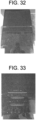
- FIGS. 32 and 33 and FIGS. 34 and 35 show different deadfront articles having different levels of optical density, and thus, these figures demonstrate the different appearance between deadfront articles 400 in which the optical density is too high in the illuminated regions ( FIGS. 32 and 33 ) and in which the optical density is within the above-described ranges for the illuminated regions ( FIGS. 34 and 35 ).
- the deadfront article has a carbon fiber pattern in which the optical density of the semi-transparent layer is too high.
- the illuminated region is obscured.
- the center icon 430 is a power button 420 that has been provided with a red color using a color layer 650.
- the deadfront article 400 may be placed over or in front of a display 530 in some embodiments.
- the display may include a touch-enabled displays which include a display and touch panel.
- Exemplary displays include LED (light emitting diode) displays ( FIG. 8 ), a DLP (digital micromirror device) MEMS chip ( FIG. 9 ), LCDs (liquid crystal displays), OLED (organic light emitting diode) displays, transmissive displays, reflective displays and the like.
- the display 530 is affixed or mounted to the deadfront article 400 using, e.g., an optically clear adhesive 540.
- the deadfront article 400 has a transmittance from about 5% to 30% along the visible spectrum, i.e., a wavelength from 400 nm to 700 nm. In other words, the deadfront article 400 exhibits an average light transmittance in a range from about 5% to about 30% along the entire wavelength range from about 400 nm to about 700 nm.
- the term "transmittance" is defined as the percentage of incident optical power within a given wavelength range transmitted through a material (e.g., the deadfront article, the substrate or the layers thereof).
- the deadfront article 400 is a low transmittance deadfront article in which light transmission is 10% or less over the entire visible spectrum.
- the opaque layer 510 may not be necessary to obscure the edges of the display 530, i.e., non-display regions, such as a display border, and/or wiring, connectors, etc.
- the deadfront article 400 is a high transmittance deadfront article exhibiting an average transmittance from about 10% to about 30%. In such embodiments, the opaque layer 510 may be necessary to block non-display regions from being seen.
- the deadfront article 400 is provided with touch functionality as shown in FIG. 10 .
- the deadfront article 400 includes substrate 450, a black semi-transparent layer 460, and a contrast layer 470 that is disposed on portions of the substrate 450 and of the semi-transparent layer 460.
- the contrast layer 470 and the semi-transparent layer 460 define an icon or a graphic, such as a power button 420 (e.g., as shown in FIGS. 2 and 3 ).
- touch functionality is provided by capacitive sensing.
- the capacitive sensor is created by a transparent conductive film or coating 550.
- the transparent conductive film 550 is a transparent conductive oxide (e.g., indium-tin-oxide (ITO)) coated polyester (e.g., PET) film.
- ITO indium-tin-oxide
- a light source 570 Upon activation of a toggle switch (e.g., by touching the deadfront article 400 in the region of the transparent conductive film 550), a light source 570 is activated or deactivated 570.
- the light source 570 includes a red LED 580 and a green LED 590.
- the red LED 580 and green LED 590 indicate the status of the deadfront article 400. For example, prior to turning the vehicle on, both the red LED 580 and green LED 590 are off as shown at the bottom of the legend of the power button 420 states on the left of FIG. 10 .
- the red LED 580 is on while the green LED 590 is off (top of the legend of power button 420 states), signifying that the display 530 is inactive.
- the toggle switch 560 will turn off the red LED 580, turn on the green LED 590, and activate the display 530. If the user desires to inactivate the display 530 while the vehicle is still on, the user can again touch the power button 420, and the toggle switch 560 will turn off the green LED 590, turn on the red LED 580, and shut off the display 530.
- a vibration motor 600 is provided to provide haptic feedback each time the toggle switch 560 is activated.
- the touch-functionality is suitable for other features.
- the touch-functionality is suitable for use in controlling a variety of vehicle systems, such as climate control (i.e., heating and air conditioning) systems, radio/entertainment systems, dashboard display panels (for, e.g., speedometer, odometer, trip odometer, tachometer, vehicle warning indicators, etc.), and center console display panels (for, e.g., GPS displays, in-vehicle information, etc.), among others.
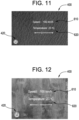
- the deadfront article 400 is depicted with a speedometer 610 and climate controls 620.
- the deadfront article 400 includes a leather grain pattern.
- FIG. 12 provides a substantially similar deadfront article 400 with a speedometer 610 and climate controls 620, but the deadfront article 400 includes a wood grain pattern.
- the substrate 450 is treated (e.g., via sandblasting, etching, engraving, etc.) in the area of a button to provide tactile feedback to a user's finger. In this way, the user can feel the deadfront article 400 for the button without removing his or her eyes from the road (in road vehicle settings).
- the toggle switch 560 is provided with a delay of, e.g., one to three seconds so as to avoid accidental activation of the toggle switch 560.
- FIG. 36 provides another embodiment of a deadfront article 400 with touch functionality.
- the deadfront article 400 includes a touch panel 660.
- the touch panel 660 can be any of a variety of suitable touch panels, such as a resistive touch panel, a capacitive (e.g., surface or projected) touch panel, a surface acoustic wave touch panel, an infrared touch panel, an optical imaging touch panel, dispersive signal touch panel, or an acoustic pulse recognition touch panel.
- the touch panel 660 is laminated to the deadfront article 400 using an optically clear adhesive 540.
- the touch panel 660 is printed onto the deadfront article 400 such that the optically clear adhesive 540 is unnecessary.
- the touch panel 660 is cold bendable to provide a three-dimensional shape. Cold bending of the deadfront article 400 (including the touch panel 660) is described in greater detail further below.
- the semi-transparent layer 460 and the contrast layer 470 are disposed on the substrate 450.
- the semi-transparent layer 460 is printed onto the substrate using a CMYK color model.
- the contrast layer is not white, such as gray
- the CMYK color model can also be used to print the contrast layer 470.
- color models that incorporate white ink can be used for printing the contrast layer 470.
- the printed semi-transparent layer 460 and the printed contrast layer 470 may each have a thickness of from 1 ⁇ m to 6 ⁇ m.
- the color layer 650 also has a thickness of from 1 ⁇ m to 6 ⁇ m. Further, in some embodiments, the color layer 650 is printed onto the opaque layer 510 and/or the contrast layer 470. In certain embodiments, the color layer 650 is printed onto the opaque layer 510 and/or contrast layer 470 using the CMYK color model.
- the ink used for printing the semi-transparent layer 460, the contrast layer 470, and/or the color layer 650 can be thermal or UV cured ink.
- the ink is composed of at least one or more colorants and a vehicle.
- the colorants can be soluble or insoluble in the vehicle.
- the colorants are dry colorants in the form of a fine powder. Such fine powders have particles that are, in some embodiments, from 10 nm to 500 nm in size.
- the colorant provides cyan, magenta, yellow, and/or key (black) colors.
- the colorant can be any of a variety of suitable pigments, such as TiO 2 , Sb 2 O 3 , BaSO 4 , BaSO 4 :ZnS, ZnO, and (PbCO 3 ) 2 :Pb(OH) 2 .
- suitable pigments such as TiO 2 , Sb 2 O 3 , BaSO 4 , BaSO 4 :ZnS, ZnO, and (PbCO 3 ) 2 :Pb(OH) 2 .
- the colorants are dissolved or suspended in the vehicle.
- the vehicle can serve as a binder to create adhesion to the surface upon which the ink is applied. Further, in some embodiments, additives are included in the vehicle specifically for the purpose of improving adhesion to glass/plastic surfaces.
- vehicles for the colorant include propylene glycol monomethyl ether, diethylene glycol diethyl ether, dimethylacetamide, and toluene. Generally, such vehicles solidify at temperatures from 80 °C to 200 °C.
- the ink includes from 0.5% - 6% by volume of the colorant and 94% - 99.5% by volume of the vehicle.
- a leather grain semi-transparent layer 460 was printed on to the substrate 450, specifically using an inkjet printer according to a CMYK color model (although, in other embodiments, other printer types and/or printing models are used).
- a white contrast layer 470 was printed behind the semi-transparent layer 460.
- FIGS. 13B and 14B depict the back sides of these printed layers.
- the contrast of the leather grain pattern of the semi-transparent layer 460 is enhanced by the white contrast layer 470 in FIG. 14A .
- the overall appearance of the pattern or design in the semi-transparent layer 460 is brighter, and the contrast between the colors in the pattern or design is enhanced.
- FIG. 15 depicts contrast layers 470 printed over a glass background.
- the contrast layers 470 are of varying whiteness (W).
- W whiteness
- "Whiteness” as used herein refers to the CIE whiteness, or ISO 11475:2004, which measures the amount of light reflected by a white surface over the visible spectrum (wavelength of 400 nm to 700 nm).
- the lower left corner of FIG. 15 is a contrast layer of 100W.
- the whiteness of the contrast layer 470 decreases from 100W to 60W going left to right along the bottom row, and along the top row, whiteness decreases from 50W to 10W going left to right.
- relatively lower whiteness contrast layers 470 transmit more light than relatively higher whiteness contrast layer 470.
- the data for generating the graph of FIG. 16 was calculated after printing white ink having diethylene glycol diethyl ether solvent and using a 128 nozzle, 40 pL printhead.
- the transmittance (T) is controlled through manipulation of printing resolution and layer thickness
- the deadfront article 400 is provided with a contrast layer 470 having a whiteness of between 10W and 60W.
- the contrast layer 470 has a whiteness of between 20W and 50W.
- the contrast layer 470 has a whiteness of between 20W and 30W.
- FIG. 17 depicts four glass substrates 450 having a semi-transparent layer 460 and contrast layer 470 printed thereon.
- the semi-transparent layers 460 feature designs of a knitted fabric pattern, a leather grain pattern, and two wood grain patterns.
- FIG. 18 depicts a semi-transparent layer 460 that transitions from a leather grain pattern to a solid black pattern.
- a green power button is also printed in the lower left corner.
- FIGS. 19 and 20 provide a comparison between the same knitted fabric pattern semi-transparent layer 460.
- a contrast layer 470 was printed behind the semi-transparent layer 460.
- the deadfront article 400 has a transmittance of between 5% and 10% over the visible spectrum (wavelength of 400 nm to 700 nm).
- FIGS. 21 and 22 depict a marble deadfront article 400.
- FIG. 21 is the viewer side of the deadfront article 400
- FIG. 22 is the rear side of the deadfront article 400.
- a section of the semi-transparent layer 460 is not covered with the contrast layer 470.
- a display could be mounted to the section not covered by the contrast layer 470.
- deadfront article 2000 may be any of the deadfront embodiments discussed herein.
- deadfront article 2000 includes a curved outer glass substrate 2010 having at least a first radius of curvature, R1, and in various embodiments, curved outer glass substrate 2010 is a complex curved sheet of glass material having at least one additional radius of curvature.
- R1 is in a range from about 60 mm to about 1500 mm.
- Curved deadfront article 2000 includes a deadfront colored layer 2020 (e.g., the ink/pigment layer(s), as discussed above) located along an inner, major surface of curved outer glass substrate 2010.
- deadfront colored layer 2020 is printed, colored, shaped, etc. to provide a wood-grain design, a leather-grain design, a fabric design, a brushed metal design, a graphic design, a solid color and/or a logo.
- embodiments of the invention are not limited to these designs or patterns.
- Curved deadfront article 2000 also may include any of the additional layers 2030 (e.g., high optical density layers, light guide layers, reflector layers, display module(s), display stack layers, light sources, touch panels, etc.) as discussed above or that otherwise may be associated with a display or vehicle interior system as discussed herein.
- additional layers 2030 e.g., high optical density layers, light guide layers, reflector layers, display module(s), display stack layers, light sources, touch panels, etc.
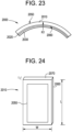
- curved deadfront article 2000 including glass substrate 2010 and colored layer 2020 may be cold-formed together to a curved shape, as shown in FIG. 23 .
- curved deadfront article 2000 including glass substrate 2010, colored layer 2020 and additional layers 2030 may be cold-formed together to a curved shape, such as that shown in FIG. 23 .
- glass substrate 2010 may be formed to a curved shape, and then layers 2020 and 2030 are applied following curve formation.
- outer glass substrate 2010 is shown prior to being formed to the curved shape shown in FIG. 24 .
- the articles and processes discussed herein provide high quality deadfront articles utilizing glass of sizes, shapes, compositions, strengths, etc. not previously provided.
- outer glass substrate 2010 includes a first major surface 2050 and a second major surface 2060 opposite first major surface 2050.
- An edge surface or minor surface 2070 connects the first major surface 2050 and the second major surface 2060.
- Outer glass substrate 2010 has a thickness (t) that is substantially constant and is defined as a distance between the first major surface 2050 and the second major surface 2060.
- the thickness (t) as used herein refers to the maximum thickness of the outer glass substrate 2010.
- Outer glass substrate 2010 includes a width (W) defined as a first maximum dimension of one of the first or second major surfaces orthogonal to the thickness (t), and outer glass substrate 2010 also includes a length (L) defined as a second maximum dimension of one of the first or second surfaces orthogonal to both the thickness and the width.
- W width
- L length
- the dimensions discussed herein are average dimensions.
- outer glass substrate 2010 has a thickness (t) that is in a range from 0.05 mm to 2 mm. In various embodiments, outer glass substrate 2010 has a thickness (t) that is about 1.5 mm or less.
- the thickness may be in a range from about 0.1 mm to about 1.5 mm, from about 0.15 mm to about 1.5 mm, from about 0.2 mm to about 1.5 mm, from about 0.25 mm to about 1.5 mm, from about 0.3 mm to about 1.5 mm, from about 0.35 mm to about 1.5 mm, from about 0.4 mm to about 1.5 mm, from about 0.45 mm to about 1.5 mm, from about 0.5 mm to about 1.5 mm, from about 0.55 mm to about 1.5 mm, from about 0.6 mm to about 1.5 mm, from about 0.65 mm to about 1.5 mm, from about 0.7 mm to about 1.5 mm, from about 0.1 mm to about 1.4 mm, from about 0.1 mm to about 1.3 mm, from about 0.1 mm to about 1.5
- outer glass substrate 2010 has a width (W) in a range from about 5 cm to about 250 cm, from about 10 cm to about 250 cm, from about 15 cm to about 250 cm, from about 20 cm to about 250 cm, from about 25 cm to about 250 cm, from about 30 cm to about 250 cm, from about 35 cm to about 250 cm, from about 40 cm to about 250 cm, from about 45 cm to about 250 cm, from about 50 cm to about 250 cm, from about 55 cm to about 250 cm, from about 60 cm to about 250 cm, from about 65 cm to about 250 cm, from about 70 cm to about 250 cm, from about 75 cm to about 250 cm, from about 80 cm to about 250 cm, from about 85 cm to about 250 cm, from about 90 cm to about 250 cm, from about 95 cm to about 250 cm, from about 100 cm to about 250 cm, from about 110 cm to about 250 cm, from about 120 cm to about 250 cm, from about 130 cm to about 250 cm, from about 140 cm to about 250 cm, from about 150 cm to about 250 cm, from about 5 cm to about 240
- outer glass substrate 2010 has a length (L) in a range from about 5 cm to about 250 cm, from about 10 cm to about 250 cm, from about 15 cm to about 250 cm, from about 20 cm to about 250 cm, from about 25 cm to about 250 cm, from about 30 cm to about 250 cm, from about 35 cm to about 250 cm, from about 40 cm to about 250 cm, from about 45 cm to about 250 cm, from about 50 cm to about 250 cm, from about 55 cm to about 250 cm, from about 60 cm to about 250 cm, from about 65 cm to about 250 cm, from about 70 cm to about 250 cm, from about 75 cm to about 250 cm, from about 80 cm to about 250 cm, from about 85 cm to about 250 cm, from about 90 cm to about 250 cm, from about 95 cm to about 250 cm, from about 100 cm to about 250 cm, from about 110 cm to about 250 cm, from about 120 cm to about 250 cm, from about 130 cm to about 250 cm, from about 140 cm to about 250 cm, from about 150 cm to about 250 cm, from about 5 cm to about 240
- outer glass substrate 2010 is shaped to a curved shaping having at least one radius of curvature, shown as R1.
- outer glass substrate 2010 may be shaped to the curved shape via any suitable process, including cold-forming and hot-forming.
- outer glass substrate 2010 is shaped to the curved shape shown in FIG. 23 , either alone, or following attachment of layers 2020 and 2030, via a cold-forming process.
- cold-bent refers to curving the glass substrate at a cold-form temperature which is less than the softening point of the glass (as described herein).
- a feature of a cold-formed glass substrate is an asymmetric surface compressive between the first major surface 2050 and the second major surface 2060. In some embodiments, prior to the cold-forming process or being cold-formed, the respective compressive stresses in the first major surface 2050 and the second major surface 2060 are substantially equal.
- the first major surface 2050 and the second major surface 2060 exhibit no appreciable compressive stress, prior to cold-forming.
- the first major surface 2050 and the second major surface 2060 exhibit substantially equal compressive stress with respect to one another, prior to cold-forming.
- the compressive stress on the second major surface 2060 e.g., the concave surface following bending
- increases i.e., the compressive stress on the second major surface 2050 is greater after cold-forming than before cold-forming).
- the cold-forming process increases the compressive stress of the glass substrate being shaped to compensate for tensile stresses imparted during bending and/or forming operations.
- the cold-forming process causes the second major surface 2060 to experience compressive stresses, while the first major surface 2050 (e.g., the convex surface following bending) experiences tensile stresses.
- the tensile stress experienced by surface 2050 following bending results in a net decrease in surface compressive stress, such that the compressive stress in surface 2050 of a strengthened glass sheet following bending is less than the compressive stress in surface 2050 when the glass sheet is flat.
- first major surface and the second major surface (2050,2060) are already under compressive stress, and thus first major surface 2050 can experience greater tensile stress during bending without risking fracture.
- the thickness of outer glass substrate 2010 is tailored to allow outer glass substrate 2010 to be more flexible to achieve the desired radius of curvature. Moreover, a thinner outer glass substrate 2010 may deform more readily, which could potentially compensate for shape mismatches and gaps that may be created by the shape of a support or frame (as discussed below). In one or more embodiments, a thin and strengthened outer glass substrate 2010 exhibits greater flexibility especially during cold-forming. The greater flexibility of the glass substrate discussed herein may allow for consistent bend formation without heating.
- outer glass substrate 2010 (and consequently deadfront article 2000) may have a compound curve including a major radius and a cross curvature.
- a complexly curved cold-formed outer glass substrate 2010 may have a distinct radius of curvature in two independent directions.
- the complexly curved cold-formed outer glass substrate 2010 may thus be characterized as having "cross curvature," where the cold-formed outer glass substrate 2010 is curved along an axis (i.e., a first axis) that is parallel to a given dimension and also curved along an axis (i.e., a second axis) that is perpendicular to the same dimension.
- the curvature of the cold-formed outer glass substrate 2010 can be even more complex when a significant minimum radius is combined with a significant cross curvature, and/or depth of bend.
- display assembly 2100 is shown according to an exemplary embodiment.
- display assembly 2100 includes frame 2110 supporting (either directly or indirectly) both a light source, shown as a display module 2120, and deadfront article 2000.
- deadfront article 2000 and display module 2120 are coupled to frame 2110, and display module 2120 is positioned to allow a user to view light, images, etc. generated by display module 2120 through deadfront article 2000.
- frame 2110 may be formed from a variety of materials such as plastic (PC/ABS, etc.), metals (Al-alloys, Mg-alloys, Fe-alloys, etc.).
- FIG. 25 shows a light source in the form of a display module
- display assembly 2100 may include any of the light sources discussed herein for producing graphics, icons, images, displays, etc. through any of the dead front embodiments discussed herein.
- frame 2110 is shown as a frame associated with a display assembly, frame 2110 may be any support or frame article associated with a vehicle interior system.
- deadfront article 2000 allows for formation of deadfront article 2000 to conform to a wide variety of curved shapes that frame 2110 may have.
- frame 2110 has a support surface 2130 that has a curved shape
- deadfront article 2000 is shaped to match the curved shape of support surface 2130.
- deadfront structure 2000 may be shaped into a wide variety of shapes to conform to a desired frame shape of a display assembly 2100, which in turn may be shaped to fit the shape of a portion of a vehicle interior system, as discussed herein.
- deadfront structure 2000 (and specifically outer glass substrate 2010) is shaped to have a first radius of curvature, R1, of about 60 mm or greater.
- R1 may be in a range from about 60 mm to about 1500 mm, from about 70 mm to about 1500 mm, from about 80 mm to about 1500 mm, from about 90 mm to about 1500 mm, from about 100 mm to about 1500 mm, from about 120 mm to about 1500 mm, from about 140 mm to about 1500 mm, from about 150 mm to about 1500 mm, from about 160 mm to about 1500 mm, from about 180 mm to about 1500 mm, from about 200 mm to about 1500 mm, from about 220 mm to about 1500 mm, from about 240 mm to about 1500 mm, from about 250 mm to about 1500 mm, from about 260 mm to about 1500 mm, from about 270 mm to about 1500 mm, from about 280 mm to about 1500 mm, from about 290 mm to about 1500
- support surface 2130 has a second radius of curvature of about 60 mm or greater.
- the second radius of curvature of support surface 2130 may be in a range from about 60 mm to about 1500 mm, from about 70 mm to about 1500 mm, from about 80 mm to about 1500 mm, from about 90 mm to about 1500 mm, from about 100 mm to about 1500 mm, from about 120 mm to about 1500 mm, from about 140 mm to about 1500 mm, from about 150 mm to about 1500 mm, from about 160 mm to about 1500 mm, from about 180 mm to about 1500 mm, from about 200 mm to about 1500 mm, from about 220 mm to about 1500 mm, from about 240 mm to about 1500 mm, from about 250 mm to about 1500 mm, from about 260 mm to about 1500 mm, from about 270 mm to about 1500 mm, from about 280 mm to about 1500 mm, from about 290 mm to about 1500 mm, from about
- deadfront structure 2000 is cold-formed to exhibit a first radius curvature, R1, that is within 10% (e.g., about 10% or less, about 9% or less, about 8% or less, about 7% or less, about 6% or less, or about 5% or less) of the second radius of curvature of support surface 2130 of frame 2110.
- R1 first radius curvature
- support surface 2130 of frame 2110 exhibits a radius of curvature of 1000 mm
- deadfront article 2000 is cold-formed to have a radius of curvature in a range from about 900 mm to about 1100 mm.
- first major surface 2050 and/or second major surface 2060 of glass substrate 2010 includes a functional coating layer as described herein.
- the functional coating layer may cover at least a portion of first major surface 2050 and/or second major surface 2060.
- Exemplary functional coatings include at least one of a glare reduction coating or surface, an anti-glare coating or surface, a scratch resistance coating, an anti-reflection coating, a half-mirror coating, or easy-to-clean coating.
- a method 2200 for forming a display assembly that includes a cold-formed deadfront article, such as deadfront article 2000 is shown.
- the method includes curving a deadfront article, such deadfront article 2000, to a curved surface of a support.
- the support may be a frame of a display, such as frame 2110 that defines a perimeter and curved shape of a vehicle display.
- the frame includes a curved support surface, and one of the major surfaces 2050 and 2060 of deadfront article 2000 is placed into contact with the curved support surface.
- the method includes securing the curved deadfront article to the support causing the deadfront article to bend into conformity (or conform) with the curved surface of the support.
- a curved deadfront article 2000 is formed from a generally flat deadfront article to a curved deadfront article.
- curving the flat deadfront article forms a curved shape on the major surface facing the support, while also causing a corresponding (but complimentary) curve to form in the major surface opposite of the frame.
- the force applied in step 2210 and/or step 2220 may be air pressure applied via a vacuum fixture.
- the air pressure differential is formed by applying a vacuum to an airtight enclosure surrounding the frame and the deadfront article.
- the airtight enclosure is a flexible polymer shell, such as a plastic bag or pouch.
- the air pressure differential is formed by generating increased air pressure around the deadfront article and the frame with an overpressure device, such as an autoclave. Air pressure provides a consistent and highly uniform bending force (as compared to a contact-based bending method) which further leads to a robust manufacturing process.
- the air pressure differential is between 0.5 and 1.5 atmospheres of pressure (atm), specifically between 0.7 and 1.1 atm, and more specifically is 0.8 to 1 atm.
- the temperature of the deadfront article is maintained below the glass transition temperature of the material of the outer glass layer during steps 2210 and 2220.
- method 2200 is a cold-forming or cold-bending process.
- the temperature of the deadfront article is maintained below 500 degrees C, 400 degrees C, 300 degrees C, 200 degrees C or 100 degrees C.
- the deadfront article is maintained at or below room temperature during bending.
- the deadfront article is not actively heated via a heating element, furnace, oven, etc. during bending, as is the case when hot-forming glass to a curved shape.
- the cold-forming processes discussed herein are believed to generate curved deadfront articles with a variety of properties that are believed to be superior to those achievable via hot-forming processes.
- heating during hot-forming processes decreases optical properties of curved glass substrates, and thus, the curved glass-based deadfront articles formed utilizing the cold-bending processes/systems discussed herein provide for both curved glass shape along with improved optical qualities not believed achievable with hot-bending processes.
- coatings and layers are applied via deposition processes, such as sputtering processes that are typically ill-suited for coating on to a curved surface.
- coating materials such as the deadfront ink/pigment materials, also are not able to survive the high temperatures associated with hot-bending processes.
- layer 2020 is applied to outer glass substrate 2010 prior to cold-bending.
- the processes and systems discussed herein allow for bending of glass after one or more coating material has been applied to the glass, in contrast to typical hot-forming processes.
- the curved deadfront article is attached or affixed to the curved support.
- the attachment between the curved deadfront article and the curved support may be accomplished via an adhesive material.
- Such adhesives may include any suitable optically clear adhesive for bonding the deadfront article in place relative to the display assembly (e.g., to the frame of the display).
- the adhesive may include an optically clear adhesive available from 3M Corporation under the trade name 8215.
- the thickness of the adhesive may be in a range from about 200 ⁇ m to about 500 ⁇ m.
- the adhesive material may be applied in a variety of ways.
- the adhesive is applied using an applicator gun and made uniform using a roller or a draw down die.
- the adhesives discussed herein are structural adhesives.
- the structural adhesives may include an adhesive selected from one or more of the categories: (a) Toughened Epoxy (Masterbond EP21TDCHT-LO, 3M Scotch Weld Epoxy DP460 Off-white); (b) Flexible Epoxy (Masterbond EP21TDC-2LO, 3M Scotch Weld Epoxy 2216 B/A Gray); (c) Acrylic (LORD Adhesive 410/Accelerator 19 w/ LORD AP 134 primer, LORD Adhesive 852/LORD Accelerator 25GB, Loctite HF8000, Loctite AA4800); (d) Urethanes (3M Scotch Weld Urethane DP640 Brown); and (e) Silicones (Dow Corning 995).
- structural glues available in sheet format may be utilized.
- pressure sensitive structural adhesives such as 3M VHB tapes may be utilized. In such embodiments, utilizing a pressure sensitive adhesive allows for the curved deadfront article to be bonded to the frame without the need for a curing step.
- the method includes step 2240 in which the curved deadfront is secured to a display.
- the method may include securing the display to the deadfront article before step 2210 and curving both the display and the deadfront article in step 2210.
- the method includes disposing or assembling the curved deadfront and display in a vehicle interior system 100, 200, 300.
- the substrate (e.g., outer glass layer 2010) of a deadfront article is formed to curved shape at step 2310. Shaping at step 2310 may be either cold-forming or hot-forming.
- the deadfront ink/pigment layer(s) e.g., layer 2020
- the curved deadfront article is attached to a frame, such as frame 2110 of display assembly 2100, or other frame that may be associated with a vehicle interior system.
- the various substrates of the deadfront articles discussed herein may be formed from any transparent material such as a polymer (e.g., PMMA, polycarbonate and the like) or glass.
- Suitable glass compositions include soda lime glass, aluminosilicate glass, borosilicate glass, boroaluminosilicate glass, alkali-containing aluminosilicate glass, alkali-containing borosilicate glass, and alkali-containing boroaluminosilicate glass.
- a substrate discussed herein may be formed of a "glass-ceramic" material produced through controlled crystallization of glass.
- glass-ceramics have about 30% to about 90% crystallinity.
- Non-limiting examples of glass ceramic systems that may be used include Li 2 O ⁇ Al 2 O 3 ⁇ nSiO 2 (i.e. LAS system), MgO ⁇ Al 2 O 3 ⁇ nSiO 2 (i.e. MAS system), and ZnO ⁇ Al 2 O 3 ⁇ nSiO 2 (i.e. ZAS system).
- the glass compositions disclosed herein are described in mole percent (mol%) as analyzed on an oxide basis.
- the glass composition may include SiO 2 in an amount in a range from about 66 mol% to about 80 mol%, from about 67 mol% to about 80 mol%, from about 68 mol% to about 80 mol%, from about 69 mol% to about 80 mol%, from about 70 mol% to about 80 mol%, from about 72 mol% to about 80 mol%, from about 65 mol% to about 78 mol%, from about 65 mol% to about 76 mol%, from about 65 mol% to about 75 mol%, from about 65 mol% to about 74 mol%, from about 65 mol% to about 72 mol%, or from about 65 mol% to about 70 mol%, and all ranges and sub-ranges therebetween.
- the glass composition includes Al 2 O 3 in an amount greater than about 4 mol%, or greater than about 5 mol%. In one or more embodiments, the glass composition includes Al 2 O 3 in a range from greater than about 7 mol% to about 15 mol%, from greater than about 7 mol% to about 14 mol%, from about 7 mol% to about 13 mol%, from about 4 mol% to about 12 mol%, from about 7 mol% to about 11 mol%, from about 8 mol% to about 15 mol%, from 9 mol% to about 15 mol%, from about 9 mol% to about 15 mol%, from about 10 mol% to about 15 mol%, from about 11 mol% to about 15 mol%, or from about 12 mol% to about 15 mol%, and all ranges and sub-ranges therebetween. In one or more embodiments, the upper limit of Al 2 O 3 may be about 14 mol%, 14.2 mol%, 14.4 mol%, 14.6 mol%, or
- glass layer(s) herein are described as an aluminosilicate glass article or including an aluminosilicate glass composition.
- the glass composition or article formed therefrom includes SiO 2 and Al 2 O 3 and is not a soda lime silicate glass.
- the glass composition or article formed therefrom includes Al 2 O 3 in an amount of about 2 mol% or greater, 2.25 mol% or greater, 2.5 mol% or greater, about 2.75 mol% or greater, about 3 mol% or greater.
- the glass composition comprises B 2 O 3 (e.g., about 0.01 mol% or greater). In one or more embodiments, the glass composition comprises B 2 O 3 in an amount in a range from about 0 mol% to about 5 mol%, from about 0 mol% to about 4 mol%, from about 0 mol% to about 3 mol%, from about 0 mol% to about 2 mol%, from about 0 mol% to about 1 mol%, from about 0 mol% to about 0.5 mol%, from about 0.1 mol% to about 5 mol%, from about 0.1 mol% to about 4 mol%, from about 0.1 mol% to about 3 mol%, from about 0.1 mol% to about 2 mol%, from about 0.1 mol% to about 1 mol%, from about 0.1 mol% to about 0.5 mol%, and all ranges and sub-ranges therebetween. In one or more embodiments, the glass composition is substantially free of B 2 O 3 .
- the phrase "substantially free” with respect to the components of the composition means that the component is not actively or intentionally added to the composition during initial batching, but may be present as an impurity in an amount less than about 0.001 mol%.
- the glass composition optionally comprises P 2 O 5 (e.g., about 0.01 mol% or greater). In one or more embodiments, the glass composition comprises a non-zero amount of P 2 O 5 up to and including 2 mol%, 1.5 mol%, 1 mol%, or 0.5 mol%. In one or more embodiments, the glass composition is substantially free of P 2 O 5 .
- the glass composition may include a total amount of R 2 O (which is the total amount of alkali metal oxide such as Li 2 O, Na 2 O, K 2 O, Rb 2 O, and Cs 2 O) that is greater than or equal to about 8 mol%, greater than or equal to about 10 mol%, or greater than or equal to about 12 mol%.
- R 2 O which is the total amount of alkali metal oxide such as Li 2 O, Na 2 O, K 2 O, Rb 2 O, and Cs 2 O
- the glass composition includes a total amount of R 2 O in a range from about 8 mol% to about 20 mol%, from about 8 mol% to about 18 mol%, from about 8 mol% to about 16 mol%, from about 8 mol% to about 14 mol%, from about 8 mol% to about 12 mol%, from about 9 mol% to about 20 mol%, from about 10 mol% to about 20 mol%, from about 11 mol% to about 20 mol%, from about 12 mol% to about 20 mol%, from about 13 mol% to about 20 mol%, from about 10 mol% to about 14 mol%, or from 11 mol% to about 13 mol%, and all ranges and sub-ranges therebetween.
- the glass composition may be substantially free of Rb 2 O, Cs 2 O or both Rb 2 O and Cs 2 O.
- the R 2 O may include the total amount of Li 2 O, Na 2 O and K 2 O only.
- the glass composition may comprise at least one alkali metal oxide selected from Li 2 O, Na 2 O and K 2 O, wherein the alkali metal oxide is present in an amount greater than about 8 mol% or greater.
- the glass composition comprises Na 2 O in an amount greater than or equal to about 8 mol%, greater than or equal to about 10 mol%, or greater than or equal to about 12 mol%.
- the composition includes Na 2 O in a range from about from about 8 mol% to about 20 mol%, from about 8 mol% to about 18 mol%, from about 8 mol% to about 16 mol%, from about 8 mol% to about 14 mol%, from about 8 mol% to about 12 mol%, from about 9 mol% to about 20 mol%, from about 10 mol% to about 20 mol%, from about 11 mol% to about 20 mol%, from about 12 mol% to about 20 mol%, from about 13 mol% to about 20 mol%, from about 10 mol% to about 14 mol%, or from 11 mol% to about 16 mol%, and all ranges and sub-ranges therebetween.
- the glass composition includes less than about 4 mol% K 2 O, less than about 3 mol% K 2 O, or less than about 1 mol% K 2 O.
- the glass composition may include K 2 O in an amount in a range from about 0 mol% to about 4 mol%, from about 0 mol% to about 3.5 mol%, from about 0 mol% to about 3 mol%, from about 0 mol% to about 2.5 mol%, from about 0 mol% to about 2 mol%, from about 0 mol% to about 1.5 mol%, from about 0 mol% to about 1 mol%, from about 0 mol% to about 0.5 mol%, from about 0 mol% to about 0.2 mol%, from about 0 mol% to about 0.1 mol%, from about 0.5 mol% to about 4 mol%, from about 0.5 mol% to about 3.5 mol%, from about 0.5 mol% to about 3 mol%, from about 0.5
- the glass composition is substantially free of Li 2 O.
- the amount of Na 2 O in the composition may be greater than the amount of Li 2 O. In some instances, the amount of Na 2 O may be greater than the combined amount of Li 2 O and K 2 O. In one or more alternative embodiments, the amount of Li 2 O in the composition may be greater than the amount of Na 2 O or the combined amount of Na 2 O and K 2 O.
- the glass composition may include a total amount of RO (which is the total amount of alkaline earth metal oxide such as CaO, MgO, BaO, ZnO and SrO) in a range from about 0 mol% to about 2 mol%. In some embodiments, the glass composition includes a non-zero amount of RO up to about 2 mol%.
- RO alkaline earth metal oxide
- the glass composition comprises RO in an amount from about 0 mol% to about 1.8 mol%, from about 0 mol% to about 1.6 mol%, from about 0 mol% to about 1.5 mol%, from about 0 mol% to about 1.4 mol%, from about 0 mol% to about 1.2 mol%, from about 0 mol% to about 1 mol%, from about 0 mol% to about 0.8 mol%, from about 0 mol% to about 0.5 mol%, and all ranges and sub-ranges therebetween.
- the glass composition includes CaO in an amount less than about 1 mol%, less than about 0.8 mol%, or less than about 0.5 mol%. In one or more embodiments, the glass composition is substantially free of CaO.
- the glass composition comprises MgO in an amount from about 0 mol% to about 7 mol%, from about 0 mol% to about 6 mol%, from about 0 mol% to about 5 mol%, from about 0 mol% to about 4 mol%, from about 0.1 mol% to about 7 mol%, from about 0.1 mol% to about 6 mol%, from about 0.1 mol% to about 5 mol%, from about 0.1 mol% to about 4 mol%, from about 1 mol% to about 7 mol%, from about 2 mol% to about 6 mol%, or from about 3 mol% to about 6 mol%, and all ranges and sub-ranges therebetween.
- the glass composition comprises ZrO 2 in an amount equal to or less than about 0.2 mol%, less than about 0.18 mol%, less than about 0.16 mol%, less than about 0.15 mol%, less than about 0.14 mol%, less than about 0.12 mol%.
- the glass composition comprises ZrO 2 in a range from about 0.01 mol% to about 0.2 mol%, from about 0.01 mol% to about 0.18 mol%, from about 0.01 mol% to about 0.16 mol%, from about 0.01 mol% to about 0.15 mol%, from about 0.01 mol% to about 0.14 mol%, from about 0.01 mol% to about 0.12 mol%, or from about 0.01 mol% to about 0.10 mol%, and all ranges and sub-ranges therebetween.
- the glass composition comprises SnO 2 in an amount equal to or less than about 0.2 mol%, less than about 0.18 mol%, less than about 0.16 mol%, less than about 0.15 mol%, less than about 0.14 mol%, less than about 0.12 mol%.
- the glass composition comprises SnO2 in a range from about 0.01 mol% to about 0.2 mol%, from about 0.01 mol% to about 0.18 mol%, from about 0.01 mol% to about 0.16 mol%, from about 0.01 mol% to about 0.15 mol%, from about 0.01 mol% to about 0.14 mol%, from about 0.01 mol% to about 0.12 mol%, or from about 0.01 mol% to about 0.10 mol%, and all ranges and sub-ranges therebetween.
- the glass composition may include an oxide that imparts a color or tint to the glass articles.
- the glass composition includes an oxide that prevents discoloration of the glass article when the glass article is exposed to ultraviolet radiation.
- oxides include, without limitation oxides of: Ti, V, Cr, Mn, Fe, Co, Ni, Cu, Ce, W, and Mo.
- the glass composition includes Fe expressed as Fe 2 O 3 , wherein Fe is present in an amount up to (and including) about 1 mol%. In some embodiments, the glass composition is substantially free of Fe. In one or more embodiments, the glass composition comprises Fe 2 O 3 in an amount equal to or less than about 0.2 mol%, less than about 0.18 mol%, less than about 0.16 mol%, less than about 0.15 mol%, less than about 0.14 mol%, less than about 0.12 mol%.
- the glass composition comprises Fe 2 O 3 in a range from about 0.01 mol% to about 0.2 mol%, from about 0.01 mol% to about 0.18 mol%, from about 0.01 mol% to about 0.16 mol%, from about 0.01 mol% to about 0.15 mol%, from about 0.01 mol% to about 0.14 mol%, from about 0.01 mol% to about 0.12 mol%, or from about 0.01 mol% to about 0.10 mol%, and all ranges and sub-ranges therebetween.
- TiO 2 may be present in an amount of about 5 mol% or less, about 2.5 mol% or less, about 2 mol% or less or about 1 mol% or less. In one or more embodiments, the glass composition may be substantially free of TiO 2 .
- An exemplary glass composition includes SiO 2 in an amount in a range from about 65 mol% to about 75 mol%, Al 2 O 3 in an amount in a range from about 8 mol% to about 14 mol%, Na 2 O in an amount in a range from about 12 mol% to about 17 mol%, K 2 O in an amount in a range of about 0 mol% to about 0.2 mol%, and MgO in an amount in a range from about 1. 5 mol% to about 6 mol%.
- SnO 2 may be included in the amounts otherwise disclosed herein.
- the substrate includes a glass material (such as outer glass substrate 2010 or other glass substrate) of any of the deadfront article embodiments discussed herein.
- a glass material such as outer glass substrate 2010 or other glass substrate
- such glass substrates may be strengthened.
- the glass substrate may be strengthened to include compressive stress that extends from a surface to a depth of compression (DOC). The compressive stress regions are balanced by a central portion exhibiting a tensile stress. At the DOC, the stress crosses from a positive (compressive) stress to a negative (tensile) stress.
- DOC depth of compression
- the glass substrates used in the deadfront articles discussed herein may be strengthened mechanically by utilizing a mismatch of the coefficient of thermal expansion between portions of the glass to create a compressive stress region and a central region exhibiting a tensile stress.
- the glass substrate may be strengthened thermally by heating the glass to a temperature above the glass transition point and then rapidly quenching.
- the glass substrate used in the deadfront articles discussed herein may be chemically strengthening by ion exchange.
- ions at or near the surface of the glass substrate are replaced by - or exchanged with - larger ions having the same valence or oxidation state.
- ions in the surface layer of the article and the larger ions are monovalent alkali metal cations, such as Li + , Na + , K + , Rb + , and Cs + .
- monovalent cations in the surface layer may be replaced with monovalent cations other than alkali metal cations, such as Ag + or the like.
- the monovalent ions (or cations) exchanged into the glass substrate generate a stress.
- Ion exchange processes are typically carried out by immersing a glass substrate in a molten salt bath (or two or more molten salt baths) containing the larger ions to be exchanged with the smaller ions in the glass substrate.
- a molten salt bath or two or more molten salt baths
- aqueous salt baths may also be utilized.
- the composition of the bath(s) may include more than one type of larger ion (e.g., Na+ and K+) or a single larger ion.
- parameters for the ion exchange process including, but not limited to, bath composition and temperature, immersion time, the number of immersions of the glass substrate in a salt bath (or baths), use of multiple salt baths, additional steps such as annealing, washing, and the like, are generally determined by the composition of the glass substrate (including the structure of the substrate and any crystalline phases present) and the desired DOC and CS of the substrate that results from strengthening.
- Exemplary molten bath composition may include nitrates, sulfates, and chlorides of the larger alkali metal ion.
- Typical nitrates include KNO 3 , NaNO 3 , LiNO 3 , NaSO 4 and combinations thereof.
- the temperature of the molten salt bath typically is in a range from about 380°C up to about 450°C, while immersion times range from about 15 minutes up to about 100 hours depending on the glass thickness, bath temperature and glass (or monovalent ion) diffusivity. However, temperatures and immersion times different from those described above may also be used.
- the glass substrate used to in the deadfront articles may be immersed in a molten salt bath of 100% NaNO 3 , 100% KNO 3 , or a combination of NaNO 3 and KNO 3 having a temperature from about 370 °C to about 480 °C.
- the glass substrate of a deadfront article may be immersed in a molten mixed salt bath including from about 5% to about 90% KNO 3 and from about 10% to about 95% NaNO 3 .
- the glass substrate may be immersed in a second bath, after immersion in a first bath.
- the first and second baths may have different compositions and/or temperatures from one another.
- the immersion times in the first and second baths may vary. For example, immersion in the first bath may be longer than the immersion in the second bath.
- the glass substrate used to form the deadfront articles may be immersed in a molten, mixed salt bath including NaNO 3 and KNO 3 (e.g., 49%/51%, 50%/50%, 51%/49%) having a temperature less than about 420 °C (e.g., about 400 °C or about 380 °C). for less than about 5 hours, or even about 4 hours or less.
- a molten, mixed salt bath including NaNO 3 and KNO 3 (e.g., 49%/51%, 50%/50%, 51%/49%) having a temperature less than about 420 °C (e.g., about 400 °C or about 380 °C). for less than about 5 hours, or even about 4 hours or less.
- Ion exchange conditions can be tailored to provide a "spike” or to increase the slope of the stress profile at or near the surface of the resulting glass substrate of a deadfront article.
- the spike may result in a greater surface CS value.
- This spike can be achieved by single bath or multiple baths, with the bath(s) having a single composition or mixed composition, due to the unique properties of the glass compositions used in the glass substrate of a deadfront article described herein.
- the different monovalent ions may exchange to different depths within the glass substrate (and generate different magnitudes stresses within the glass substrate at different depths).
- the resulting relative depths of the stress-generating ions can be determined and cause different characteristics of the stress profile.
- CS is measured using those means known in the art, such as by surface stress meter (FSM) using commercially available instruments such as the FSM-6000, manufactured by Orihara Industrial Co., Ltd. (Japan).
- FSM surface stress meter
- FSM-6000 manufactured by Orihara Industrial Co., Ltd. (Japan).
- SOC stress optical coefficient
- SOC fiber and four-point bend methods, both of which are described in ASTM standard C770-98 (2013), entitled “Standard Test Method for Measurement of Glass Stress-Optical Coefficient," and a bulk cylinder method.
- CS may be the "maximum compressive stress" which is the highest compressive stress value measured within the compressive stress layer. In some embodiments, the maximum compressive stress is located at the surface of the glass substrate. In other embodiments, the maximum compressive stress may occur at a depth below the surface, giving the compressive profile the appearance of a "buried peak.”
- DOC may be measured by FSM or by a scattered light polariscope (SCALP) (such as the SCALP-04 scattered light polariscope available from Glasstress Ltd., located in Tallinn Estonia), depending on the strengthening method and conditions.
- SCALP scattered light polariscope
- FSM or SCALP may be used depending on which ion is exchanged into the glass substrate.
- FSM is used to measure DOC.
- SCALP is used to measure DOC.
- the DOC is measured by SCALP, since it is believed the exchange depth of sodium indicates the DOC and the exchange depth of potassium ions indicates a change in the magnitude of the compressive stress (but not the change in stress from compressive to tensile); the exchange depth of potassium ions in such glass substrate is measured by FSM.
- Central tension or CT is the maximum tensile stress and is measured by SCALP.
- the glass substrate used to form the deadfront articles maybe strengthened to exhibit a DOC that is described a fraction of the thickness t of the glass substrate (as described herein).
- the DOC may be equal to or greater than about 0.05t, equal to or greater than about 0.1t, equal to or greater than about 0.11t, equal to or greater than about 0.12t, equal to or greater than about 0.13t, equal to or greater than about 0.14t, equal to or greater than about 0.15t, equal to or greater than about 0.16t, equal to or greater than about 0.17t, equal to or greater than about 0.18t, equal to or greater than about 0.19t, equal to or greater than about 0.2t, equal to or greater than about 0.21t.
- the DOC may be in a range from about 0.08t to about 0.25t, from about 0.09t to about 0.25t, from about 0.18t to about 0.25t, from about 0.11t to about 0.25t, from about 0.12t to about 0.25t, from about 0.13t to about 0.25t, from about 0.14t to about 0.25t, from about 0.15t to about 0.25t, from about 0.08t to about 0.24t, from about 0.08t to about 0.23t, from about 0.08t to about 0.22t, from about 0.08t to about 0.21t, from about 0.08t to about 0.2t, from about 0.08t to about 0.19t, from about 0.08t to about 0.18t, from about 0.08t to about 0.17t, from about 0.08t to about 0.16t, or from about 0.08t to about 0.15t.
- the DOC may be about 20 ⁇ m or less. In one or more embodiments, the DOC may be about 40 ⁇ m or greater (e.g., from about 40 ⁇ m to about 300 ⁇ m, from about 50 ⁇ m to about 300 ⁇ m, from about 60 ⁇ m to about 300 ⁇ m, from about 70 ⁇ m to about 300 ⁇ m, from about 80 ⁇ m to about 300 ⁇ m, from about 90 ⁇ m to about 300 ⁇ m, from about 100 ⁇ m to about 300 ⁇ m, from about 110 ⁇ m to about 300 ⁇ m, from about 120 ⁇ m to about 300 ⁇ m, from about 140 ⁇ m to about 300 ⁇ m, from about 150 ⁇ m to about 300 ⁇ m, from about 40 ⁇ m to about 290 ⁇ m, from about 40 ⁇ m to about 280 ⁇ m, from about 40 ⁇ m to about 260 ⁇ m, from about 40 ⁇ m to about 250 ⁇ m, from about 40 ⁇ m to about 240 ⁇ m, from
- the glass substrate used to form the deadfront articles may have a CS (which may be found at the surface or a depth within the glass article) of about 200 MPa or greater, 300 MPa or greater, 400 MPa or greater, about 500 MPa or greater, about 600 MPa or greater, about 700 MPa or greater, about 800 MPa or greater, about 900 MPa or greater, about 930 MPa or greater, about 1000 MPa or greater, or about 1050 MPa or greater.
- CS which may be found at the surface or a depth within the glass article
- the glass substrate used to form the deadfront articles may have a maximum tensile stress or central tension (CT) of about 20 MPa or greater, about 30 MPa or greater, about 40 MPa or greater, about 45 MPa or greater, about 50 MPa or greater, about 60 MPa or greater, about 70 MPa or greater, about 75 MPa or greater, about 80 MPa or greater, or about 85 MPa or greater.
- CT maximum tensile stress or central tension
- the maximum tensile stress or central tension (CT) may be in a range from about 40 MPa to about 100 MPa.
- FIGS. 37-40 illustrate a substrate 700 including one or more tactile elements.
- Substrate 700 includes a first surface 702, a second surface 704 opposite first surface 702, and at least one edge surface 706 extending between first and second surfaces 702, 704.
- An article (e.g., deadfront article 400) that includes substrate 700 may include an outer surface (e.g., outer surface 480) defined by first surface 702 of substrate 700.
- the user of the article may both see and touch first surface 702 of substrate 700 when interacting with the article.
- Substrate 700 includes at least one visual element 710-1, 710-2 disposed on second surface 704 of substrate 700 such that the at least one visual element may be viewed through first surface 702 thereof. Additionally and/or alternatively, at least one visual element 710-1, 710-2 may be disposed within the substrate 700 using known techniques (e.g., using pigmented glass, etc.). Visual element(s) 710-1, 710-2 may be or may include one or more graphics visible through first surface 702. In some embodiments, the one or more graphics may include one or more icons.
- At least one visual element 710-1, 710-2 may be defined in whole or in part by an opaque layer (e.g., opaque layer 510).
- the opaque layer may be provided to outline backlit icons and/or other graphics (such as the graphic 410 and/or power button 420 shown in FIGS. 2 and 3 , the icons 430 shown in FIG. 5 , or the graphics 820 shown in FIG. 41 ).
- the opaque layer has interruptions in the layer that define visual element(s) 710-1, 710-2.
- opaque layer 510 may be a masking layer that defines visual element(s) 710-1, 710-2.
- Visual element(s) 710-1, 710-2 may include one or more visual portions arranged into at least one of: (i) one or more areas of color, (ii) one or more lines, (iii) one or more patterns, (iv) one or more designs, (v) one or more images, (vi) one or more graphics, and (vii) one or more combinations thereof.
- a first visual element 710-1 may be a circle formed via color, lines, patterns, shading, masking, design, etc.
- a second visual element 710-2 may be a triangle formed via color, lines, patterns, shading, masking, design, etc.
- visual element(s) 710-1, 710-2 may be disposed on second surface 704 of substrate 700, serving as an inner surface of an article (e.g., inner surface 490 of deadfront article 400).
- visual element(s) 710-1, 710-2 may be seen by the user through fist surface 702 of substrate 700 but the visual element(s) 710-1, 710-2 are protected from wear or damage by way of being disposed on second surface 704 of substrate 700.
- additional and/or alternative embodiments may include the at least one visual element 710-1, 710-2 disposed within substrate 700.
- substrate 700 includes at least one tactile element 712-1, 712-2.
- the combination of the at least one visual element 710-1, 710-2 and the at least one tactile element 712-1, 712-2 may be combined in such a way as to enhance the look and/or the feel of an article.
- tactile element(s) 712-1, 712-2 may enhance the feel of the article in the user's hand or the feel of an article's surface.
- the tactile element(s) 712-1, 712-2 may also operate in such a way that visual element(s) 710-1, 710-2 is/are visually enhanced as compared to an article without tactile element(s) 712-1, 712-2.
- a notably visually stimulating (depth and/or three-dimensional) effect has been discovered by providing visual element(s) 710-1, 710-2 on second surface 704 of substrate 700 and providing tactile element(s) 712-1, 712-2 in a complimentary fashion on first surface 702 of substrate 700.
- a similar affect may be achieved for visual elements(s) 710-1, 710-2 disposed within substrate 700.
- the complimentary nature of providing at least one tactile element 712-1, 712-2 may include providing one or more portions of surface roughness and/or small surface elements that complement the color(s), line(s), pattern(s), design(s), graphics, and/or image(s), etc. of at least one visual element 710-1, 710-2.
- a surface roughness discussed herein may be quantified, for example, as exhibiting an R a surface roughness of between about 10 nm and about 80 nm for a relatively smooth surface roughness (including subranges), between about 80 nm and about 300 nm for a relatively moderate surface roughness (including subranges), and greater than about 300 nm for a relatively rough surface roughness.
- a relatively smooth surface roughness may have a R a surface roughness of 10 nm, 20 nm, 30 nm, 40 nm, 50 nm, 60 nm, 70 nm, 80 nm, or a R a surface roughness in a range having any two of these values as endpoints.
- a relatively moderate surface roughness may have a R a surface roughness of 80 nm, 100 nm, 125 nm, 150 nm, 175 nm, 200 nm, 225 nm, 250 nm, 275 nm, or 300 nm, or R a surface roughness in a range having any two of these values as endpoints.
- the height difference characteristics of the small surface elements discussed herein may be implemented via relatively small elements extending away from a surface of the substrate and may be quantified, for example, as having a height of between about 10 nm and about 80 nm for a relatively smooth surface roughness, between about 80 nm and about 300 nm for a relatively moderate surface roughness, and greater than about 300 nm for a relatively rough surface roughness.
- Surface roughness (R a ) may be measured using a surface profilometer available from Zygo Corp.
- the aforementioned provision of providing at least one tactile element 712-1, 712-2 in a commentary fashion to at least one visual element 710-1, 710-2 may include providing lines, areas, designs, shapes, patterns, etc. of surface roughness and/or small surface elements on first surface 702 of the substrate 700 that substantially match (e.g., are in registration with) corresponding lines, shapes, patterns, graphics, colors, etc. of at least one visual element 710-1, 710-2.
- two objects disposed or positioned in a "complimentary fashion” means that the two objects have substantially the same overall shape, perimeter shape, design, and/or pattern, and occupy substantially the same relative surface area on opposing surfaces of a substrate.
- the overall shape, perimeter shape, design, and/or pattern, and the relative surface area of such an object is the overall shape, perimeter shape, design, and/or pattern, and surface area of that object projected onto a surface of the substrate opposite the surface on which the corresponding object is disposed or positioned in a complimentary fashion.
- FIG. 37 illustrates a first visual element 710-1 positioned on second surface 704 in a complementary fashion to a first tactile element 712-1 on first surface 702 of substrate 700.
- FIG. 37 illustrates a second visual element 710-2 positioned on second surface 704 in a complementary fashion to a second tactile element 712-2 on first surface 702 of substrate 700.
- desirable visual effects may be obtained without disposing objects in a complementary fashion.
- at least one tactile element 712-1, 712-2 may be disposed in a non-commentary fashion (e.g., offset fashion) to at least one visual element 710-1, 710-2 to produce desirable visual effect.
- Tactile element(s) 712-1, 712-2 include one or more surface roughness portions and/or small surface elements arranged into at least one of: (i) one or more areas of surface roughness and/or small surface elements, (ii) one or more lines of surface roughness and/or small surface elements, (iii) one or more patterns of surface roughness and/or small surface elements, (iv) one or more designs of surface roughness and/or small surface elements, and (v) one or more combinations thereof.
- first tactile element 712-1 may be a circle formed via a line of elevated surface roughness and/or small surface elements, or a line of reduced surface roughness and/or small surface elements
- second tactile element 712-2 may be a triangle formed via a line of elevated surface roughness and/or small surface elements, or a line of reduced surface roughness and/or small surface elements.
- tactile element(s) 712-1, 712-2 may be applied to first surface 702 of substrate 700 in such a way that first surface 702 serves as an outer surface of an article.
- First surface 702 of substrate 700 may be subject to surface processing in order to provide some level of surface roughening (e.g., a hazing effect) that provides some tactile feedback to the user.
- the level of surface roughness and/or small surface elements may range from a feeling of smooth (very little or no surface roughness and/or small surface elements), to a feeling of velvety softness (moderate levels of surface roughness, such as a matte surface roughness, and/or moderate levels of small surface elements), to a feeling of substantial roughness (higher levels of roughness and/or small surface elements) in order to achieve design goals.
- the surface roughness portions (and/or small surface element portions) of tactile element(s) 712-1, 712-2 are positioned on first surface 702 of substrate 700 in a complimentary fashion with respect to at least some of the visual portions of visual element(s) 710-1, 710-2.
- Such an arrangement may modify the visual effect of the visual element(s) 710-1, 710-2 as viewed through first surface 702 of substrate 700.
- the complementary arrangement may provide a three-dimensional visual effect, particularly at some viewing angles.
- first tactile element 712-1 positioned in a complimentary fashion to first visual element 710-1 may be achieved via a first surface roughness portion (and/or small surface element portion) of first tactile element 712-1 in the form of a line (e.g., a circular outline) of complementary size and shape as the circle of first visual element 710-1.
- second tactile element 712-2 positioned in a complimentary fashion to second visual element 710-2 may be achieved via a second surface roughness portion (and/or small surface element portion) of second tactile element 712-2 in the form of a line (e.g., a triangular outline) of complementary size and shape as the triangle of second visual element 710-2.
- the surface roughness portions (and/or small surface element portions) of tactile element(s) 712-1, 712-2 may be achieved in any number of ways.
- the surface roughness portions (and/or small surface element portion) may be defined by an area (e.g., a circle, a triangle, a circular and/or triangular area) of relatively higher surface roughness (and/or higher surface element height) that is positioned in the visually complimentary fashion with respect to corresponding visual element(s) 710-1 and/or 710-2 bordered by at least one area of relatively lower surface roughness(and/or lower surface element height).
- One way of achieving such an effect is to provide: (i) a majority of a total surface area of first surface 702 of substrate 700 as a relatively smooth finish of relatively low surface roughness (e.g., ranging from no surface roughness or no surface element height to some low or moderate level of surface roughness, such as a matte finish surface roughness, and/or moderate level of surface element height); and (ii) the area of relatively higher surface roughness, and/or higher surface element height (e.g., the circular and/or triangular outline, circular and/or triangular area) of tactile element(s) 712-1 and/or 712-2 as a minority of the total surface area of first surface 702 and include at least some portions of such circular and/or triangular outline via a surface roughness and/or surface element height that is relatively rougher (e.g., ranging from a moderate level of surface roughness and/or moderate surface element height to a high level of surface roughness and/or high surface element height) as compared with the smooth finish.
- the surface roughness portions and/or surface element portions of tactile element(s) 712-1, 712-2 may be achieved via an area of relatively lower surface roughness and/or lower surface element height that is positioned in the visually complimentary fashion bordered by at least one area of relatively higher surface roughness.
- One way of achieving such an effect is to provide: (i) a majority of a total surface area of first surface 702 of substrate 700 as a relatively rough finish (e.g., ranging from some moderate level of surface roughness, such as from rougher than a matte finish surface roughness, and/or some moderate level of surface element height, to some high level of surface roughness and/or some high level of surface element height); and (ii) the area of relatively lower surface roughness and/or relatively lower surface element height (e.g., the circle, the triangle, the circular and/or triangular outline) of tactile element(s) 712-1 and/or 712-2 as a minority of the total surface area of first surface 702 and include at least some portions of such circle, triangle, circular and/or triangular outline, via a surface roughness and/or surface element height that is relatively smoother (e.g., ranging from no surface roughness and/or no surface element height to some low level of surface roughness and/or low level of surface element height) as compared with the rough finish
- FIGS. 38-39 contain schematic images of substrate 700 as it moves through the process. Steps illustrated and described are not exhaustive; other steps can be performed before, after, or between any of the described and illustrated steps. In some embodiments, the steps may be performed in a different order. Variations of the process illustrated in FIGS. 38-39 are within the scope of the present disclosure.
- At least one tactile element 710-1, 710-2 is achieved via surface roughness characteristics.
- the process disclosed in FIGS. 38-39 is one in which at least one tactile element 712-1, 712-2 is achieved via a majority of a total surface area of first surface 702 of substrate 700 being relatively smooth and relatively higher surface roughness portions of at least one tactile element 712-1, 712-2 being disposed in a complementary fashion with respect to at least one visual element 710-1, 710-2.
- substantially all of second surface 704 of the substrate 700 is masked with an etch resistant material (e.g., with an etch resistive ink, as shown in black at step 750).
- an etch resistant material e.g., with an etch resistive ink, as shown in black at step 750.
- at least first surface 702 of substrate 700 is exposed (e.g., dipped, sprayed, etc.) to an acid solution (etching solution) to generate a low to medium level of surface roughness on first surface 702, such as a matte finish surface roughness.
- the resultant matte finish is shown in grey at step 752 in which the etch resistive ink has been removed to expose the relatively smooth finish of the second surface 704 of the substrate 700 (shown in white at step 752).
- second surface 704 of substrate 700 may not be directly masked with an etch resistant material, but instead may be protected from an etching solution in an alternative fashion.
- step 752 may be performed on a substrate 700 defining a portion of an article (e.g., deadfront article 400), in which case any portions of the article which are not intended to be etched in step 752 may be protected from the etching solution using suitable materials or apparatuses.
- the etching solution used in step 752 may include hydrofluoric acid, ammonium fluoride, and a water miscible organic solvent.
- the etching solution in step 752 may include 1-15 wt% (weight percent) hydrofluoric acid, 1-40 wt% ammonium fluoride, 0-35 wt% water miscible organic solvent, and water.
- the etching solution in step 752 may comprise 4-10 wt% hydrofluoric acid, 5-30 wt% ammonium fluoride, 0-25wt% water miscible organic solvent, and water.
- the water miscible organic solvent in the etching solution in step 752 may be an alcohol, ethylene glycol, propylene glycol, glycerol, or combinations thereof.
- Suitable alcohols include ethanol and iso-propanol.
- an etch resistive material (e.g., etch resistive ink mask, shown in black in step 754) is applied to first surface 702 of substrate 700.
- the etch resistive material is applied to achieve the aforementioned tactile element(s) 712-1, 712-2 that will eventually be complementary to visual element(s) 710-1, 710-2.
- substantially all of second surface 704 of substrate 700 may be masked or protected from an etching solution in step 754 (shown in black in step 754).
- Substrate 700 is again exposed (e.g., dipped, sprayed, etc.) to an acid (etching) solution that is designed to polish (reduce the roughness) of the un-masked regions of first surface 702 of substrate 700.
- the acid solution may also reduce the thickness of substrate 700 in the un-masked regions via material removal.
- the resulting matte finish and tactile elements are shown in step 756 in which the etch resistive material has been removed to expose the previously masked portions of first surface 702 (shown in dark gray at step 756).
- the previously masked portions of first surface 702 will thus be of a higher surface roughness than the un-masked regions of the first surface 702, which have been polished and somewhat thinned.
- all portions of first surface 702 except those corresponding to the position of tactile element(s) 712-1, 712-2 that will eventually be complementary to visual element(s) 710-1, 710-2 may be masked in step 754.
- tactile element(s) 712-1, 712-2 may lower surface roughness than un-masked regions around the tactile element(s) 712-1, 712-2.
- the etching solution used in step 756 may include hydrofluoric acid. In some embodiments, the etching solution used in step 756 may include 1-10 wt % hydrofluoric acid. In some embodiments, the etching solution in step 756 may include 5 wt % hydrofluoric acid.
- substrate 700 may also be exposed to a strengthening process, for example a thermal strengthening process or a chemical strengthening process (known in the art as an ion exchange process). In some embodiments, this optional strengthening process may be performed after step 756.
- a strengthening process for example a thermal strengthening process or a chemical strengthening process (known in the art as an ion exchange process). In some embodiments, this optional strengthening process may be performed after step 756.
- the at least one visual element 710-1, 710-2 is disposed on second surface 704 of substrate 700.
- step 758 may include disposing one or more layers to form a deadfront article.
- a semi-transparent layer e.g., semi-transparent layer 460
- a contrast layer e.g., contrast layer 470
- a color layer e.g., color layer 650
- an opaque layer e.g., opaque layer 510
- a process for enhancing the visibility of at least one visual element 710-1, 710-2 through first surface 702 of substrate 700 may be carried out.
- a bright (and preferably neutral) pigment layer such as white
- the bright layer is shown in step 760 as white.
- desirable enhancement of the visibility of visual element(s) 710-1, 710-2 may be achieved when the "bright" layer is a shiny black and/or metallic coating applied over visual element(s) 710-1, 710-2 on second surface 704.
- FIG. 40 An alternative process for achieving the application of at least one tactile element 712-1, 712-2 and at least one visual element 710-1, 710-2 on substrate 700 is illustrated in FIG. 40 , which contains schematic images of substrate 700 as it moves through the alternative process.
- at least one tactile element 710-1, 710-2 is again achieved via surface roughness characteristics.
- the process disclosed in FIG. 40 is one in which at least one tactile element 712-1, 712-2 is achieved via a majority of a total surface area of first surface 702 of the substrate 700 being of a relatively high surface roughness and relatively lower surface roughness portions of at least one tactile element 712-1, 712-2 being disposed in a complementary way with respect to at least one visual element 710-1, 710-2.
- Steps illustrated and described are not exhaustive; other steps can be performed before, after, or between any of the described and illustrated steps. In some embodiments, the steps may be performed in a different order. Variations of the process illustrated in FIG. 40 are within the scope of the present disclosure.
- step 780 substantially all of second surface 704 of substrate 700 is masked or protected with an etch resistive material (e.g., with an etch resistive ink, as shown in black at step 780).
- second surface 704 of substrate 700 may not be directly masked with an etch resistant material, but instead may be protected from an etching solution in alternative fashion.
- step 780 may be performed on a substrate 700 defining a portion of an article (e.g., deadfront article 400), in which case any portions of the article which are not intended to be etched in step 780 may be protected from the etching solution using suitable materials or apparatuses.
- an etch resistive material (e.g., etch resistive ink mask, as shown in black at step 780) is applied to first surface 702 of substrate 700.
- the etch resistive material is applied to first surface 702 to achieve the aforementioned at least one tactile element 712-1, 712-2.
- substrate 700 is exposed (e.g., dipped, sprayed, etc.) to an acid solution to generate a low to medium level of surface roughness on the un-masked portions of first surface 702, such as a matte finish surface roughness.
- an acid solution to generate a low to medium level of surface roughness on the un-masked portions of first surface 702, such as a matte finish surface roughness.
- alternative embodiments may employ the acid solution in such a way to produce higher levels of surface roughness.
- the etch resistive material may then be removed to expose one or more areas, lines, patterns, designs, combinations thereof, etc. that are of a relatively smooth finish (shown in white at step 782) on first surface 702 among the other portions that are of a low to medium level of surface roughness (or alternatively even higher levels of roughness, as shown in grey at step 782).
- the etching solution used in step 782 may include hydrofluoric acid, ammonium fluoride, and a water miscible organic solvent.
- the etching solution in step 782 may include 1-15 wt% (weight percent) hydrofluoric acid, 1-40 wt% ammonium fluoride, 0-35 wt% water miscible organic solvent, and water.
- the etching solution in step 782 may comprise 4-10 wt% hydrofluoric acid, 5-30 wt% ammonium fluoride, 0-25wt% water miscible organic solvent, and water.
- the water miscible organic solvent in the etching solution in step 782 may be an alcohol, ethylene glycol, propylene glycol, glycerol, or combinations thereof.
- Suitable alcohols include ethanol and iso-propanol.
- the etching solution used in step 782 may include hydrofluoric acid. In some embodiments, the etching solution used in step 782 may include 1-10 wt % hydrofluoric acid. In some embodiments, the etching solution in step 756 may include 5 wt % hydrofluoric acid.
- this involves applying visual element(s) 710-1, 710-2 in such a way that it may be viewed through first surface 702.
- This may involve ink printing, ink spraying, masking, coating, photolithography, etc., to provide one or more visual portions arranged into at least one of, or defining at least one of: (i) one or more areas of color, (ii) one or more lines, (iii) one or more patterns, (iv) one or more designs, (v) one or more images, (vi) one or more graphics, and (vii) one or more combinations thereof.
- step 784 may include disposing one or more layers to form a deadfront article.
- a semi-transparent layer e.g., semi-transparent layer 460
- a contrast layer e.g., contrast layer 470
- a color layer e.g., color layer 650
- an opaque layer e.g., opaque layer 510
- a process for enhancing the visibility of at least one visual element 710-1, 710-2 through the first surface 702 of substrate 700 may be carried out.
- a bright (and preferably neutral) pigment layer such as white
- white is applied over at least one visual element 710-1, 710-2 on second surface 704 by way of printing, coating, spraying, etc., as shown by white on second surface 704 at step 786.
- desirable enhancement of the visibility of at least one visual element 710-1, 710-2 may alternatively be achieved when the "bright" layer is a shiny black and/or metallic coating applied over at least one visual element 710-1, 710-2 on second surface 704.
- At least one tactile element 712-1, 712-2 may be formed from at least two differing levels of surface roughness and/or surface element heights, neither of which is the unaltered, original, smooth surface finish of substrate 700.
- step 780 may include the aforementioned printing of substantially all of second surface 704 of substrate 700 and the etch resistive material (mask).
- substrate 700 may be exposed (e.g., dipped, sprayed, etc.) to an acid solution to generate some level of surface roughness on first surface 702, such as a matte finish surface roughness.
- the etch resistive material (mask) is applied to first surface 702 of substrate 700 (i.e., over the previously formed matte finish) to achieve the aforementioned at least one tactile element 712-1, 712-2.
- substrate 700 is again exposed (e.g., dipped, sprayed, etc.) to an acid solution to generate a further level of surface roughness on the un-masked portions of first surface 702, which is rougher than the previously produced matte finish surface roughness.
- the etch resistive material may then be removed from first surface 702 to expose one or more areas, lines, patterns, designs, combinations thereof, etc. that are of the matte finish surface roughness (represented by the lines in white at steps 782, 784 in FIG. 40 ) among the other portions that are of a higher level of surface roughness (represented by the grey at steps 782, 784 in FIG. 40 ).
- steps 784 and 786 of FIG. 40 may be carried out, which would produce at least one tactile element 712-1, 712-2 formed from at least two differing levels of surface roughness, neither of which is the unaltered, original, smooth surface finish of substrate 700. While this process results in two different levels of surface roughness in order to achieve at least one tactile element 712-1, 712-2, skilled artisans will appreciate that the steps in the process may be altered (e.g., by adding steps of masking, etching, polishing, and/or other techniques) in order to achieve three or more different levels of surface roughness.
- FIGS. 41 and 42 illustrate a deadfront article 800 according to some embodiments.
- FIG. 41 illustrates article 800 when it is backlit with a visual element 810 of article 800 shown.
- FIG. 42 illustrates article 800 when it is not backlit with tactile elements 830 of article 800 shown.
- Deadfront article 800 includes a substrate 801.
- Substrate 801 may be the same as or similar to any substrate discussed herein and includes a first surface 802 a second surface 804 opposite first surface 802.
- a visual element 810 may be disposed on second surface 804 of substrate 801 and/or within substrate 801 such that visual element 810 may be viewed through first surface 802.
- Visual element 810 may include one or more graphics 820 that may be viewed through first surface 802 when article 800 is backlit (see FIG. 41 ).
- one or more graphics 820 includes or is an icon.
- visual element 810 may include a plurality of separate visual elements including one or more graphics.
- visual element 810 may include a plurality of printed, coated, sprayed, etc. layers or materials including one or more graphics.
- an "icon” is an area, line, shape, pattern, design, image, symbol, letter, number, logo, or combination thereof that represents one or more functionalities of a device.
- an icon When actuated by a user (e.g., via touch) an icon will produce a functional result represented by the icon.
- an on/off icon will power a device on or off.
- a "volume” icon will cause a device to produce more or less sound.
- An icon may also be called a button.
- Article 800 also includes at least one tactile element 830 formed on first surface 802 of substrate 801.
- tactile element(s) 830 may include one or more surface roughness portions, with at least one of the one or more surface roughness portions positioned on first surface 802 in a complimentary fashion to all or a portion of visual element 810.
- tactile element(s) 830 may include one or more surface roughness portions, with at least one of the one or more surface roughness portions positioned on first surface 802 in a complimentary fashion to a graphic 820.
- Tactile element(s) 830 create a haptic feel for a user touching first surface 802 while preserving the appearance of a deadfronted material imagined on first surface 802 (e.g., carbon fiber, stainless steel, wood, etc.) when article 800 is not backlit.
- tactile element(s) 830 may be faintly visible on first surface 802.
- a first object e.g., tactile element
- a first object formed on a surface of a second object may be formed by depositing material on the surface, removing material from the surface, and/or chemically altering one or more surface properties of the surface.
- Suitable methods for forming a first object on the surface of a second object include, but are not limited to, etching (e.g., etching with an acid), polishing, sand blasting, engraving, embossing, rolling, and/or vapor deposition (e.g., chemical or physical vapor deposition).
- tactile element(s) 830 may be etched surface portions formed by, for example, an etching process described in reference to FIGS. 38-39 or FIG. 40 .
- Deadfront article 800 also includes a deadfront assembly 840 disposed on second surface 804.
- Deadfront assembly 840 may include any layers descried herein for forming a deadfront article.
- deadfront assembly 840 may include a semi-transparent layer (e.g., semi-transparent layer 460), a contrast layer (e.g., contrast layer 470), a color layer (e.g., color layer 650), and/or an opaque layer (e.g., opaque layer 510).
- FIG. 42 illustrates a semi-transparent layer 850, which is disposed on second surface 804, visible through first surface 802 when article is not backlit.
- deadfront assembly 840 may include a high optical density layer (e.g., opaque layer 510) disposed onto at least a portion of a contrast layer (e.g., contrast layer 470) such that the contrast layer is located between the high optical density layer and the semi-transparent layer.
- the high optical density layer may at least in part define one or more graphics 820.
- deadfront article 800 may include a touch panel (e.g., touch panel 660) located behind visual element 810, the touch panel configured to respond to a touch by a user (e.g., a touch of one or more graphics 820).
- the touch panel may be configured to respond to a user's touch of graphic 820, which may be an icon.
- the portion of first surface 802 occupied by tactile element(s) 830 may be relatively rougher (i.e., may have a higher surface roughness) than all or a portion of the remainder of first surface 802.
- tactile element(s) 830 may have a Ra surface roughness of greater than about 80 nm.
- first surface 802 occupied by tactile element(s) 830 may be relatively smoother (i.e., may have a lower surface roughness) than all or a portion of the remainder of first surface 802.
- all or a portion of first surface 802 around tactile element(s) 830 may have a Ra surface roughness of greater than about 80 nm.
- deadfront article 800 may be made using a processing including one or more processes described herein in reference to FIGS. 38-40 .
- a method of forming tactile element(s) 830 on deadfront article 800 includes forming at least one tactile element 830 on first surface 802 of substrate 801 in a complimentary fashion to a graphic 820 of visual element 810 disposed on second surface 804 of substrate 801 opposite first surface 802 and/or within substrate 801 such that the graphic 820 may be viewed through first surface 802.
- indefinite articles “a” and “an” to describe an element or component means that one or at least one of these elements or components is present. Although these articles are conventionally employed to signify that the modified noun is a singular noun, as used herein the articles “a” and “an” also include the plural, unless otherwise stated in specific instances. Similarly, the definite article “the,” as used herein, also signifies that the modified noun may be singular or plural, again unless otherwise stated in specific instances.
- the term "about” means that amounts, sizes, ranges, formulations, parameters, and other quantities and characteristics are not and need not be exact, but may be approximate and/or larger or smaller, as desired, reflecting tolerances, conversion factors, rounding off, measurement error and the like, and other factors known to those of skill in the art.
- substantially is intended to note that a described feature is equal or approximately equal to a value or description.
- a “substantially planar” surface is intended to denote a surface that is planar or approximately planar.
- substantially is intended to denote that two values are equal or approximately equal.
- substantially may denote values within about 10% of each other, such as within about 5% of each other, or within about 2% of each other.
Landscapes
- Chemical & Material Sciences (AREA)
- Engineering & Computer Science (AREA)
- Organic Chemistry (AREA)
- Materials Engineering (AREA)
- Chemical Kinetics & Catalysis (AREA)
- General Chemical & Material Sciences (AREA)
- Geochemistry & Mineralogy (AREA)
- Life Sciences & Earth Sciences (AREA)
- Theoretical Computer Science (AREA)
- Physics & Mathematics (AREA)
- General Engineering & Computer Science (AREA)
- General Physics & Mathematics (AREA)
- Human Computer Interaction (AREA)
- Mechanical Engineering (AREA)
- Transportation (AREA)
- Combustion & Propulsion (AREA)
- Optics & Photonics (AREA)
- Crystallography & Structural Chemistry (AREA)
- Polymers & Plastics (AREA)
- Medicinal Chemistry (AREA)
- Health & Medical Sciences (AREA)
- Microelectronics & Electronic Packaging (AREA)
- Laminated Bodies (AREA)
- Nonlinear Science (AREA)
- Mathematical Physics (AREA)
- Surface Treatment Of Glass (AREA)
- Devices For Indicating Variable Information By Combining Individual Elements (AREA)
- Instrument Panels (AREA)
- Geometry (AREA)
- Fittings On The Vehicle Exterior For Carrying Loads, And Devices For Holding Or Mounting Articles (AREA)
- Illuminated Signs And Luminous Advertising (AREA)
- Position Input By Displaying (AREA)
- Glass Compositions (AREA)
Claims (14)
- Deadfront-Artikel für eine Fahrzeuganzeige, aufweisend:ein Trägermaterial, aufweisend:eine erste Oberfläche; undeine zweite Oberfläche entgegengesetzt zur ersten Oberfläche;ein visuelles Element, das an der zweiten Oberfläche des Trägermaterials und/oder innerhalb des Trägermaterials so angeordnet ist, dass das visuelle Element durch die erste Oberfläche hindurch sichtbar ist, wobei das visuelle Element eine Grafik aufweist, die durch die erste Oberfläche hindurch sichtbar ist;mindestens ein taktiles Element, das auf der ersten Oberfläche des Trägermaterials gebildet ist, wobei das mindestens eine taktile Element einen oder mehrere Oberflächen-Rauheitsabschnitte aufweist, wobei mindestens einer des einen oder der mehreren Oberflächen-Rauheitsabschnitte auf der ersten Oberfläche des Trägermaterials komplementär zur Grafik positioniert ist;eine semitransparente Schicht, die auf mindestens einem ersten Abschnitt der zweiten Oberfläche des Trägermaterials angeordnet ist, wobei die semitransparente Schicht einen Bereich einer Vollfarbe oder eines Designs aus zwei oder mehr Farben hat; undeine Kontrastschicht, die auf mindestens einem Abschnitt des Bereichs angeordnet ist, wobei die Kontrastschicht dafür ausgelegt ist, die Sichtbarkeit der Farbe des Bereichs zu erhöhen oder den Kontrast zwischen den Farben des Designs des Bereichs an dem Abschnitt des Bereichs zu erhöhen, auf dem die Kontrastschicht angeordnet ist;wobei das Trägermaterial ein Material ausweist, das aus der Gruppe ausgewählt ist, die aus Folgendem besteht: ein Glas, eine Glaskeramik und ein Polymer;wobei die semitransparente Schicht eine optische Dichte von 0,1 bis 0,5 für Licht mit einer Wellenlänge im Bereich von 400 nm bis 700 nm hat; undwobei die Kontrastschicht weiß ist und eine Weiße von 10W bis 60W nach ISO11475:2004 aufweist und eine optische Dichte von 0,9 bis 2,0 für Licht mit einer Wellenlänge im Bereich von 400 nm bis 700 nm hat.
- Deadfront-Artikel nach Anspruch 1, wobei der eine oder die mehreren Oberflächen-Rauheitsabschnitte definiert sind durch einen der folgenden Punkte: (i) eine Fläche mit einer relativ höheren Oberflächenrauheit, die von mindestens einer Fläche mit einer relativ niedrigeren Oberflächenrauheit begrenzt wird, und (ii) eine Fläche mit einer relativ niedrigeren Oberflächenrauheit, die von mindestens einer Fläche mit einer relativ höheren Oberflächenrauheit begrenzt wird.
- Deadfront-Artikel nach einem der vorhergehenden Ansprüche, wobei: ein Großteil eines Gesamtflächeninhalts der ersten Oberfläche des Trägermaterials eine erste Oberflächenrauheit aufweist; und
die eine oder die mehreren Oberflächen-Rauheitsabschnitte des taktilen Elements den kleineren Teil des Gesamtflächeninhalts der ersten Oberfläche bedecken und eine zweite Oberflächenrauheit aufweisen, die sich von der ersten Oberflächenrauheit unterscheidet. - Deadfront-Artikel nach Anspruch 3, wobei die zweite Oberflächenrauheit relativ rauer als die erste Oberflächenrauheit ist und die zweite Oberflächenrauheit eine Oberflächenrauheit Ra aufweist, die größer als ca. 80 nm ist; oder wobei die erste Oberflächenrauheit relativ rauer als die zweite Oberflächenrauheit ist und die erste Oberflächenrauheit eine Oberflächenrauheit Ra von größer als ca. 80 nm aufweist.
- Deadfront-Artikel nach einem der vorhergehenden Ansprüche, eine Schicht mit hoher optischer Dichte aufweisend, die auf mindestens einem Abschnitt der Kontrastschicht so angeordnet ist, dass sich die Kontrastschicht zwischen der Schicht mit hoher optischer Dichte und der semitransparenten Schicht befindet.
- Deadfront-Artikel nach Anspruch 5, wobei die Schicht mit hoher optischer Dichte die Grafik mindestens zum Teil definiert.
- Deadfront-Artikel nach Anspruch 6, darüber hinaus eine Farbschicht aufweisend, die in Bereichen des visuellen Elements so angeordnet ist, dass in mindestens einem Abschnitt des visuellen Elements, der durch die Schicht mit hoher optischer Dichte definiert ist, die Kontrastschicht sich zwischen der semitransparenten Schicht und der Farbschicht befindet.
- Deadfront-Artikel nach einem der vorhergehenden Ansprüche, wobei der Bereich der semitransparenten Schicht ein Design aus zwei oder mehr Farben hat, wobei das Design ein Ledermaserungsmuster, ein Holzmaserungsmuster, ein Gewebemuster, ein gebürstetes Metalloberflächenmuster und/oder ein Logo aufweist.
- Deadfront-Artikel nach einem der vorhergehenden Ansprüche, darüber hinaus ein Berührungsfeld aufweisend, das sich hinter dem visuellen Element befindet, wobei das Berührungsfeld dafür ausgelegt ist, auf eine Berührung durch einen Benutzer anzusprechen.
- Fahrzeuginnenraum, aufweisend:
einen Deadfront-Artikel nach Anspruch 1, wobei der Deadfront-Artikel darüber hinaus aufweist:eine Schicht mit hoher optischer Dichte, die auf mindestens einem Abschnitt der Kontrastschicht angeordnet ist, wobei die Schicht mit hoher optischer Dichte die Grafik mindestens zum Teil definiert; undein Berührungsfeld, das sich hinter dem visuellen Element befindet, wobei das Berührungsfeld dafür ausgelegt ist, auf eine Berührung durch einen Benutzer anzusprechen. - Fahrzeuginnenraum nach Anspruch 10, wobei es sich bei der Grafik um ein Piktogramm handelt und das Berührungsfeld dafür ausgelegt ist, auf eine Berührung des Piktogramms durch einen Benutzer anzusprechen.
- Fahrzeuginnenraumartikel nach Anspruch 10 oder Anspruch 11, wobei die Schicht mit hoher optischer Dichte auf mindestens einem Abschnitt der Kontrastschicht so angeordnet ist, dass sich die Kontrastschicht zwischen der Schicht mit hoher optischer Dichte und der semitransparenten Schicht befindet.
- Verfahren zur Bildung eines taktilen Elements auf dem Deadfront-Artikel nach Anspruch 1, wobei das Verfahren umfasst:Bilden des mindestens einen taktilen Elements auf der ersten Oberfläche des Trägermaterials komplementär zur Grafik, die durch das visuelle Element gebildet ist, das auf der zweiten Oberfläche des Trägermaterials entgegengesetzt zur erste Oberfläche und/oder innerhalb des Trägermaterials so angeordnet ist, dass die Grafik durch die erste Oberfläche hindurch sichtbar ist,wobei das mindestens eine taktile Element durch einen Prozess gebildet ist, der Ätzen, Sandstrahlen, Polieren und/oder Gravieren umfasst.
- Verfahren zur Bildung eines taktilen Elements auf einem Deadfront-Artikel nach Anspruch 13, wobei das mindestens eine taktile Element durch einen Ätzvorgang gebildet ist, und wobei der Ätzvorgang umfasst:Ätzen der ersten Oberfläche mit einer ersten Ätzlösung;Anordnen einer Maske über der ersten Oberfläche nach dem Ätzen der ersten Oberfläche mit der ersten Ätzlösung, wobei die Maske eine Form aufweist, die der Form der Grafik entspricht; undÄtzen eines nicht maskierten Bereichs der ersten Oberfläche mit einer zweiten Ätzlösung.
Priority Applications (1)
| Application Number | Priority Date | Filing Date | Title |
|---|---|---|---|
| EP25151132.5A EP4516750A3 (de) | 2017-09-12 | 2018-09-12 | Taktile elemente für deadfronted-glas und verfahren zur herstellung davon |
Applications Claiming Priority (4)
| Application Number | Priority Date | Filing Date | Title |
|---|---|---|---|
| US201762557502P | 2017-09-12 | 2017-09-12 | |
| US201862679278P | 2018-06-01 | 2018-06-01 | |
| US201862729695P | 2018-09-11 | 2018-09-11 | |
| PCT/US2018/050772 WO2019055581A1 (en) | 2017-09-12 | 2018-09-12 | TOUCH-SENSITIVE GLASS ELEMENTS WITH INSULATED FACE AND METHODS OF MAKING SAME |
Related Child Applications (1)
| Application Number | Title | Priority Date | Filing Date |
|---|---|---|---|
| EP25151132.5A Division EP4516750A3 (de) | 2017-09-12 | 2018-09-12 | Taktile elemente für deadfronted-glas und verfahren zur herstellung davon |
Publications (2)
| Publication Number | Publication Date |
|---|---|
| EP3681847A1 EP3681847A1 (de) | 2020-07-22 |
| EP3681847B1 true EP3681847B1 (de) | 2025-01-29 |
Family
ID=63708481
Family Applications (3)
| Application Number | Title | Priority Date | Filing Date |
|---|---|---|---|
| EP18783603.6A Active EP3681847B1 (de) | 2017-09-12 | 2018-09-12 | Taktile elemente für deadfront-glas und verfahren zu deren herstellung |
| EP25151132.5A Pending EP4516750A3 (de) | 2017-09-12 | 2018-09-12 | Taktile elemente für deadfronted-glas und verfahren zur herstellung davon |
| EP18779527.3A Active EP3681846B1 (de) | 2017-09-12 | 2018-09-12 | Deadfront für anzeigen mit einem berührungsfeld auf dekorationsglas und zugehörige verfahren |
Family Applications After (2)
| Application Number | Title | Priority Date | Filing Date |
|---|---|---|---|
| EP25151132.5A Pending EP4516750A3 (de) | 2017-09-12 | 2018-09-12 | Taktile elemente für deadfronted-glas und verfahren zur herstellung davon |
| EP18779527.3A Active EP3681846B1 (de) | 2017-09-12 | 2018-09-12 | Deadfront für anzeigen mit einem berührungsfeld auf dekorationsglas und zugehörige verfahren |
Country Status (7)
| Country | Link |
|---|---|
| US (5) | US11459268B2 (de) |
| EP (3) | EP3681847B1 (de) |
| JP (3) | JP7124065B2 (de) |
| KR (3) | KR102669222B1 (de) |
| CN (4) | CN115602068B (de) |
| TW (3) | TWI888930B (de) |
| WO (2) | WO2019055469A1 (de) |
Families Citing this family (52)
| Publication number | Priority date | Publication date | Assignee | Title |
|---|---|---|---|---|
| CN109071302B (zh) | 2016-03-09 | 2022-04-26 | 康宁股份有限公司 | 复杂弯曲玻璃制品的冷成形 |
| TWI800484B (zh) | 2016-06-28 | 2023-05-01 | 美商康寧公司 | 層壓薄強化玻璃至用於裝飾及顯示器蓋應用的曲面模製塑膠表面 |
| WO2018009504A1 (en) | 2016-07-05 | 2018-01-11 | Corning Incorporated | Cold-formed glass article and assembly process thereof |
| CN115403280B (zh) | 2016-10-25 | 2024-03-19 | 康宁公司 | 用于显示器的冷成形玻璃积层 |
| KR102445875B1 (ko) | 2017-01-03 | 2022-09-21 | 코닝 인코포레이티드 | 만곡된 커버 유리 및 디스플레이 또는 터치 패널을 갖는 차량 인테리어 시스템 및 이를 형성시키는 방법 |
| US11016590B2 (en) | 2017-01-03 | 2021-05-25 | Corning Incorporated | Vehicle interior systems having a curved cover glass and display or touch panel and methods for forming the same |
| US11685684B2 (en) * | 2017-05-15 | 2023-06-27 | Corning Incorporated | Contoured glass articles and methods of making the same |
| CN117962601A (zh) | 2017-07-18 | 2024-05-03 | 康宁公司 | 复杂弯曲玻璃制品的冷成型 |
| EP3681847B1 (de) | 2017-09-12 | 2025-01-29 | Corning Incorporated | Taktile elemente für deadfront-glas und verfahren zu deren herstellung |
| TWI873668B (zh) | 2017-09-13 | 2025-02-21 | 美商康寧公司 | 用於顯示器的基於光導器的無電面板、相關的方法及載具內部系統 |
| US11065960B2 (en) | 2017-09-13 | 2021-07-20 | Corning Incorporated | Curved vehicle displays |
| TWI844520B (zh) | 2017-10-10 | 2024-06-11 | 美商康寧公司 | 具有改善可靠性的彎曲的覆蓋玻璃的車輛內部系統及其形成方法 |
| JP6370519B1 (ja) * | 2017-10-28 | 2018-08-08 | mui Lab株式会社 | 操作表示パネル組込物品 |
| WO2019103469A1 (en) | 2017-11-21 | 2019-05-31 | Corning Precision Materials Co., Ltd. | Aspheric mirror for head-up display system and methods for forming the same |
| KR102605341B1 (ko) | 2017-11-30 | 2023-11-24 | 코닝 인코포레이티드 | 곡선형 미러를 성형하기 위한 진공 몰드 장치, 시스템, 및 방법 |
| CN111656254B (zh) | 2017-11-30 | 2023-06-02 | 康宁公司 | 用于真空成形非球面镜的系统与方法 |
| EP3759821A4 (de) * | 2018-02-26 | 2021-11-03 | Shanghai Yanfeng Jinqiao Automotive Trim Systems Co. Ltd | Fahrzeuginnenkomponente |
| WO2019169293A1 (en) | 2018-03-02 | 2019-09-06 | Corning Incorporated | Anti-reflective coatings and articles and methods of forming the same |
| US11718071B2 (en) | 2018-03-13 | 2023-08-08 | Corning Incorporated | Vehicle interior systems having a crack resistant curved cover glass and methods for forming the same |
| JP7268765B2 (ja) * | 2018-06-13 | 2023-05-08 | Agc株式会社 | 曲面に印刷層を有するカバーガラスおよびその印刷方法 |
| JP7219024B2 (ja) * | 2018-06-29 | 2023-02-07 | 日本板硝子株式会社 | カバーガラス |
| CN112672984B (zh) | 2018-07-12 | 2023-03-10 | 康宁公司 | 配置用于色彩比对的无电板 |
| KR20210032976A (ko) | 2018-07-16 | 2021-03-25 | 코닝 인코포레이티드 | 냉간-벤딩 유리 기판을 갖는 차량 내부 시스템 및 이를 형성하기 위한 방법 |
| CN111348837A (zh) * | 2018-12-20 | 2020-06-30 | 康宁股份有限公司 | 强化制品、强化玻璃制品以及制造强化制品的方法 |
| WO2020131400A1 (en) | 2018-12-21 | 2020-06-25 | Corning Incorporated | Strengthened 3d printed surface features and methods of making the same |
| US20220176821A1 (en) * | 2019-04-29 | 2022-06-09 | Corning Incorporated | Display with underlying decorative layer |
| CN118478581A (zh) | 2019-07-01 | 2024-08-13 | 阿尔卑斯阿尔派株式会社 | 装饰片及静电输入装置 |
| CN114341074A (zh) * | 2019-07-12 | 2022-04-12 | 康宁公司 | 具有超低闪光的防眩光表面及其制造方法 |
| EP3771695A1 (de) | 2019-07-31 | 2021-02-03 | Corning Incorporated | Verfahren und system zur kaltumformung von glas |
| US12466756B2 (en) | 2019-10-08 | 2025-11-11 | Corning Incorporated | Curved glass articles including a bumper piece configured to relocate bending moment from display region and method of manufacturing same |
| KR20210073691A (ko) * | 2019-12-10 | 2021-06-21 | 삼성디스플레이 주식회사 | 윈도우 제조 방법 |
| WO2021123295A1 (en) * | 2019-12-18 | 2021-06-24 | Agc Glass Europe | Cover glass sheet with differential texturing |
| US11952304B2 (en) | 2020-03-12 | 2024-04-09 | Corning Incorporated | Apparatuses, systems and methods for cold forming glass |
| JP2021152794A (ja) * | 2020-03-24 | 2021-09-30 | 株式会社デンソーテン | 入力装置 |
| US11772361B2 (en) | 2020-04-02 | 2023-10-03 | Corning Incorporated | Curved glass constructions and methods for forming same |
| US11681173B2 (en) | 2020-04-03 | 2023-06-20 | Corning Incorporated | Image panel having composite image using color changing with backlight illumination |
| KR102263657B1 (ko) * | 2020-05-22 | 2021-06-10 | 동우 화인켐 주식회사 | 초박형 글라스 및 이의 제조 방법 |
| CN111708215A (zh) * | 2020-07-14 | 2020-09-25 | 京东方科技集团股份有限公司 | 一种镜面切换屏及显示装置 |
| WO2022128753A1 (en) * | 2020-12-16 | 2022-06-23 | Agc Glass Europe | Decorative glass panel with the appearance of a noble material |
| CN113407060B (zh) * | 2021-06-28 | 2022-10-04 | 重庆大学 | 一种透光触控部件的制作方法及透光触控部件 |
| EP4457188A1 (de) | 2021-12-30 | 2024-11-06 | Corning Incorporated | Abdecksubstrate für anzeigen mit dekorativen schichten mit integrierten logikschaltungen und verfahren zur formung davon |
| JP7349546B1 (ja) | 2022-03-25 | 2023-09-22 | Solize株式会社 | 革シボを有する樹脂成形品の製造方法 |
| US20230332821A1 (en) * | 2022-04-15 | 2023-10-19 | Electrolux Home Products, Inc. | Dead-front user interface |
| WO2024072788A1 (en) | 2022-09-30 | 2024-04-04 | Corning Incorporated | Deadfront articles with multi-layer optical structures and associated methods |
| KR102763952B1 (ko) * | 2022-11-04 | 2025-02-07 | 현대모비스 주식회사 | 플라스틱 커버 렌즈 및 이를 포함하는 차량용 디스플레이 |
| TWI866261B (zh) * | 2023-06-06 | 2024-12-11 | 台亞半導體股份有限公司 | 車用曲面蓋板結構與製造方法 |
| FR3159457A1 (fr) * | 2024-02-20 | 2025-08-22 | Stellantis Auto Sas | Procédé d’affichage d’information sur un écran de planche de bord d’un véhicule automobile |
| WO2026017752A1 (en) * | 2024-07-17 | 2026-01-22 | Agc Glass Europe | Laser decoating of coated glass article |
| WO2026017763A1 (en) * | 2024-07-17 | 2026-01-22 | Agc Glass Europe | Glass sheet article with improved visual and tactile feel |
| WO2026017757A1 (en) * | 2024-07-17 | 2026-01-22 | Agc Glass Europe | Laser decoating of coated glass article |
| WO2026017761A1 (en) * | 2024-07-17 | 2026-01-22 | Agc Glass Europe | Glass sheet article with improved visual and tactile feel |
| WO2026058195A1 (en) | 2024-09-12 | 2026-03-19 | Elmann Srl | Light transmission component |
Citations (1)
| Publication number | Priority date | Publication date | Assignee | Title |
|---|---|---|---|---|
| US6420800B1 (en) * | 2000-05-25 | 2002-07-16 | Gentex Corporation | Rearview mirror with buttons incorporating display |
Family Cites Families (677)
| Publication number | Priority date | Publication date | Assignee | Title |
|---|---|---|---|---|
| US2068030A (en) | 1934-10-02 | 1937-01-19 | Leo F Lieser | Spark plug |
| US2352957A (en) | 1942-03-06 | 1944-07-04 | Corning Glass Works | Method of forming glass articles |
| US2403060A (en) | 1943-04-23 | 1946-07-02 | Pittsburgh Plate Glass Co | Installation for laminated glass |
| BE538214A (fr) | 1947-10-09 | 1955-06-15 | Libbey Owens Ford Glass Co | Moule pour le cintrage de plaques de verre |
| GB805770A (en) | 1955-06-13 | 1958-12-10 | Du Pont | Reinforced glass-containing articles based on polypyromellitimides |
| BE618737A (de) | 1961-06-12 | |||
| GB991867A (en) | 1962-06-21 | 1965-05-12 | Pirna Guss & Farbenglaswerke | Method of and apparatus for the continuous production of a bar of glass of predetermined profile |
| US3197903A (en) | 1963-05-28 | 1965-08-03 | Gerald A Walley | Dead front display |
| US3338696A (en) | 1964-05-06 | 1967-08-29 | Corning Glass Works | Sheet forming apparatus |
| US3674589A (en) | 1969-02-28 | 1972-07-04 | Ncr Co | Method of fabrication and reinforcing high solids-containing materials |
| US3582456A (en) | 1969-05-23 | 1971-06-01 | Monsanto Co | Cold-formable composites |
| BE757057A (fr) | 1969-10-06 | 1971-04-05 | Corning Glass Works | Procede et appareil de controle d'epaisseur d'une feuille de verre nouvellement etiree |
| BE758410A (fr) | 1969-11-06 | 1971-05-03 | Kalle Ag | Complexe, compose de verre et de matiere plastique |
| GB1309333A (en) | 1970-01-19 | 1973-03-07 | Glaverbel | Process for bending glass |
| US3737212A (en) | 1970-12-14 | 1973-06-05 | Gen Electric | Diffraction optics head up display |
| GB1359165A (en) | 1971-05-21 | 1974-07-10 | Glaverbel | Panels incorporating a glass sheet and the manufacture thereof |
| US3881043A (en) | 1971-06-21 | 1975-04-29 | Ppg Industries Inc | Laminated safety windshields |
| US3778335A (en) | 1971-09-02 | 1973-12-11 | Corning Glass Works | Sodium aluminosilicate glass article strengthened by a surface compressive stress layer |
| US4052236A (en) | 1974-04-11 | 1977-10-04 | Pandel-Bradford, Inc. | Method of preparing imitation sheet material |
| US4147527A (en) | 1975-03-28 | 1979-04-03 | Bystrov Nikolai M | Glass sheet molding assembly |
| FR2338229A1 (fr) | 1976-01-14 | 1977-08-12 | Bfg Glassgroup | Procede pour le pliage de feuilles de verre, dispositif et installation pour la mise en oeuvre du procede |
| JPS53147708A (en) | 1977-05-30 | 1978-12-22 | Central Glass Co Ltd | Apparatus for producing curved plate glass |
| DE2758581C2 (de) | 1977-12-29 | 1980-01-03 | Bfg Glassgroup, Paris | Windschutzscheibe, insbesondere für Kraftfahrzeuge, mit Innenscheibe aus chemisch vorgespanntem Silikatglas |
| US4238265A (en) | 1978-10-27 | 1980-12-09 | The Boeing Company | Method of manufacturing a glass parabolic-cylindrical solar collector |
| JPS55154329A (en) | 1979-05-18 | 1980-12-01 | Nec Kagoshima Ltd | Manufacture of cover glass for display tube |
| US4289520A (en) | 1979-12-17 | 1981-09-15 | Advanced Glass Systems Corporation | Method and apparatus for bending glass sheets |
| DE3012007A1 (de) | 1980-03-28 | 1981-10-08 | Gebr. Happich Gmbh, 5600 Wuppertal | Schaumstoffkoerper, insbesondere armaturentafel fuer kraftfahrzeuge |
| JPS5748082A (en) | 1980-08-30 | 1982-03-19 | Yoshida Kanamono Kk | Criminal unlocking preventer |
| US4400419A (en) | 1980-11-14 | 1983-08-23 | Antoni Laczynski | Decal assembly for inside-outside application having a reflectorized surface |
| DE3140366C2 (de) | 1981-10-10 | 1985-02-14 | Metzeler Kautschuk GmbH, 8000 München | Verfahren und Vorrichtung zur Herstellung eines Einbauteils, bestehend aus einer Scheibe und einem Dichtungs- und Halterahmen |
| US4445953A (en) | 1982-02-25 | 1984-05-01 | Ppg Industries, Inc. | Method of forming shaped laminates |
| JPS58194751A (ja) | 1982-05-04 | 1983-11-12 | Asahi Glass Co Ltd | ガラス板の曲げ加工装置 |
| JPS5976561A (ja) | 1982-10-25 | 1984-05-01 | Toshiba Corp | 核燃料再処理用遠心分離機 |
| US4470837A (en) | 1982-11-22 | 1984-09-11 | Ppg Industries, Inc. | Split ring-like support member of adjustable length for shaping glass sheets |
| US4506956A (en) * | 1983-03-29 | 1985-03-26 | Xerox Corporation | Multicolor liquid crystal display with a dead front |
| DE3400428A1 (de) | 1984-01-09 | 1985-07-18 | VEGLA Vereinigte Glaswerke GmbH, 5100 Aachen | Autoglasscheibe fuer die direktverglasung, und verfahren zum einsetzen einer autoglasscheibe in die fensteroeffnung einer fahrzeugkarosserie |
| US4508556A (en) | 1984-06-04 | 1985-04-02 | Ppg Industries, Inc. | Method and apparatus for bending glass sheets to complicated shapes including an S-shaped transverse bend |
| GB2171990B (en) | 1985-03-08 | 1988-12-07 | Central Glass Co Ltd | Method of strengthening glass article formed of float glass by ion exchange and strengthened glass article |
| FR2596751B1 (fr) | 1986-04-08 | 1988-06-03 | Saint Gobain Vitrage | Dispositif de formage du verre |
| US4802903A (en) | 1986-09-25 | 1989-02-07 | Saint-Gobain Vitrage | Method and apparatus for curving a glass sheet |
| JPS6389317A (ja) | 1986-10-03 | 1988-04-20 | Nissan Motor Co Ltd | 自動車用ウインドウエザ−ストリツプの成形方法 |
| US4746348A (en) | 1986-12-29 | 1988-05-24 | Ppg Industries, Inc. | Horizontal press bending apparatus and method |
| JPH0755841B2 (ja) | 1987-02-03 | 1995-06-14 | 旭硝子株式会社 | 合せガラス用ガラス板の曲げ加工方法 |
| CN1013957B (zh) | 1987-02-20 | 1991-09-18 | 詹姆斯·阿瑟·艾伯特·希克曼 | 耐火安全玻璃 |
| BE1000350A5 (fr) | 1987-02-27 | 1988-11-08 | Saint Roch Glaceries | Panneau vitre cintre. |
| FR2623126B1 (fr) | 1987-11-12 | 1990-02-16 | Saint Gobain Vitrage | Dispositif pour l'assemblage des vitrages feuilletes |
| LU87241A1 (fr) | 1988-06-15 | 1990-02-28 | Glaverbel | Procede d'augmentation de la resistance a la penetration au travers d'une baie vitree et vitrage a resistance a l'effraction renforcee |
| EP0347049A3 (de) | 1988-06-15 | 1990-06-13 | Dow Corning Corporation | Haftungsmischung |
| US4969966A (en) | 1989-06-26 | 1990-11-13 | Water Bonnet Manufacturing, Inc. | Method of producing curved laminated glass panels |
| US4979977A (en) | 1989-09-18 | 1990-12-25 | Ppg Industries, Inc. | Bending iron having member to effect reverse bend and method of using same |
| JPH0359337U (de) | 1989-10-12 | 1991-06-11 | ||
| JPH03131539A (ja) | 1989-10-17 | 1991-06-05 | Asahi Glass Co Ltd | 曲げ成型用プレス型とガラス板の曲げ成型方法及びその装置 |
| FR2657046B1 (fr) | 1990-01-16 | 1992-04-30 | Saint Gobain Vitrage Int | Dispositif pour l'assemblage par pressage des vitrages feuilletes. |
| JPH03228840A (ja) | 1990-02-02 | 1991-10-09 | Nippon Sheet Glass Co Ltd | ガラス容器の成形方法 |
| FR2658808B1 (fr) | 1990-02-21 | 1993-05-14 | Saint Gobain Vitrage Int | Four de bombage de feuilles de verre par effondrement sur un cadre de bombage et son application a la realisation de vitrages de forme complexe. |
| JPH04119931A (ja) | 1990-09-06 | 1992-04-21 | Asahi Glass Co Ltd | ガラス板の曲げ成形方法 |
| US5250146A (en) | 1990-11-05 | 1993-10-05 | Horvath Steven J | Apparatus for applying anti-lacerative film to glass |
| US5106671A (en) | 1990-12-10 | 1992-04-21 | Ford Motor Company | Transparent anti-reflective coating |
| US5245468A (en) | 1990-12-14 | 1993-09-14 | Ford Motor Company | Anti-reflective transparent coating |
| JP2930147B2 (ja) | 1991-06-24 | 1999-08-03 | 日本板硝子株式会社 | プレスロール装置 |
| US5220442A (en) * | 1991-09-06 | 1993-06-15 | Xerox Corporation | Method of making color liquid crystal display with dead front appearance |
| US5279635A (en) | 1992-01-08 | 1994-01-18 | Libbey-Owens-Ford Co. | Method and apparatus for controlling the temperature of glass sheets in press bending |
| US5264058A (en) | 1992-08-24 | 1993-11-23 | Monsanto | Forming a shaped prelaminate and bilayer glazing of glass and plastic |
| US5589248A (en) | 1992-09-18 | 1996-12-31 | Suntec Corporation | Shaped glass sheet and a process for the preparation thereof |
| ATE159900T1 (de) | 1993-01-16 | 1997-11-15 | Saint Gobain Vitrage | Zur verklebung in eine rahmenöffnung vorgefertigte farbzeugverglasung und herstellungsverfahren |
| GB9306444D0 (en) | 1993-03-27 | 1993-05-19 | Pilkington Aerospace Ltd | Glass component |
| KR960702384A (ko) | 1993-05-03 | 1996-04-27 | 존 에이. 포웰 | 치수안정성 강화 열가소성 pvc 물품(dimensionally stable reinforced thermoplastic pvc articles) |
| JPH06340029A (ja) | 1993-06-03 | 1994-12-13 | Asahi Chem Ind Co Ltd | ガラスフィルムと樹脂とよりなる積層板 |
| FR2707283B1 (fr) | 1993-07-09 | 1995-09-22 | Saint Gobain Vitrage Int | Procédé et dispositif de formage de plaques de verre et application de ce procédé à l'obtention de vitrages de formes complexes. |
| DE4426344C2 (de) * | 1993-09-07 | 1998-02-26 | Ford Motor Co | Anzeigeinstrument |
| DE4337559C1 (de) | 1993-11-04 | 1995-03-23 | Ver Glaswerke Gmbh | Verfahren zum paarweisen Biegen von Glasscheiben |
| SG44545A1 (en) | 1993-12-28 | 1997-12-19 | Nissha Printing | Apparatus and method for producing patterned molding articles |
| IT1267986B1 (it) | 1994-01-19 | 1997-02-20 | Fiat Auto Spa | Procedimento per la formatura di un elemento di materiale composito ed elemento di materiale composito utilizzabile in tale procedimento. |
| JP3246828B2 (ja) | 1994-03-18 | 2002-01-15 | 本田技研工業株式会社 | 車輌用ガラス保持構造 |
| JP3059337B2 (ja) | 1994-04-21 | 2000-07-04 | シャープ株式会社 | 半導体装置およびその製造方法 |
| DE4415878C2 (de) | 1994-05-05 | 1996-08-14 | Bayerische Motoren Werke Ag | Verbundglasscheibe, insbesondere für Fahrzeuge |
| US5668663A (en) | 1994-05-05 | 1997-09-16 | Donnelly Corporation | Electrochromic mirrors and devices |
| DE4415787A1 (de) | 1994-05-05 | 1995-11-09 | Tadeusz Tumalski | Schnuller-Thermometer |
| JP2694920B2 (ja) | 1994-07-28 | 1997-12-24 | 大日本印刷株式会社 | 射出成形同時絵付方法及び装置 |
| US7489303B1 (en) | 2001-02-22 | 2009-02-10 | Pryor Timothy R | Reconfigurable instrument panels |
| DE19503314C1 (de) | 1995-02-02 | 1996-06-20 | Sekurit Saint Gobain Deutsch | Für die Klebemontage vorgerüstete Glasscheibe, insbesondere Autoglasscheibe |
| JP3364081B2 (ja) | 1995-02-16 | 2003-01-08 | 株式会社半導体エネルギー研究所 | 半導体装置の作製方法 |
| GB9600247D0 (en) * | 1996-01-06 | 1996-03-06 | Contra Vision Ltd | Panel with light permeable images |
| EP0894119B1 (de) | 1996-04-15 | 2004-06-02 | Lord Corporation | Frei radikalisch polymerisierbare zusammensetzungen, die parahalogenierte anilin derivate enthalten |
| EP0816064A1 (de) | 1996-06-25 | 1998-01-07 | Saint-Gobain Vitrage | Verbundglasscheibe aus Glas und Kunststoff und Verfahren zur Bestimmung von optimalen geometrischen Parametern dieser Verbundglasscheibe |
| FR2750075B1 (fr) | 1996-06-25 | 1998-08-21 | Saint Gobain Vitrage | Vitrage feuillete et son procede de fabrication, moule pour le fabriquer et ensemble incorporant un tel vitrage |
| NL1003537C2 (nl) | 1996-07-08 | 1998-01-12 | Holland Railconsult B V | Werkwijze voor het vervaardigen van een gebogen beglazing. |
| JP3879152B2 (ja) | 1996-08-12 | 2007-02-07 | 旭硝子株式会社 | ガラス板の曲げ成形装置、曲げ成形型およびその製造方法 |
| US5916600A (en) | 1996-09-06 | 1999-06-29 | Donnelly Corporation | Mold assembly for holding a sheet of glass during molding |
| JP3753526B2 (ja) | 1996-12-18 | 2006-03-08 | サクラ精機株式会社 | 顕微鏡標本のカバーガラス貼着方法と装置 |
| JPH10218630A (ja) | 1997-02-04 | 1998-08-18 | A F C Ceramic:Kk | 鏡面成形型 |
| SE508831C2 (sv) | 1997-04-29 | 1998-11-09 | Ovako Steel Ab | Nitrerstål |
| JP4010467B2 (ja) | 1997-05-12 | 2007-11-21 | マツダ株式会社 | コンバーチブル・トップ組立体、並びにその製造方法、及び装置 |
| DE29713779U1 (de) | 1997-08-02 | 1997-10-09 | SOMMER ALLIBERT-LIGNOTOCK GmbH, 76744 Wörth | Mehrschichtiges Formteil |
| JPH1160293A (ja) | 1997-08-06 | 1999-03-02 | Nippon Sheet Glass Co Ltd | 合わせガラスおよび自動車窓構造 |
| JP3220058B2 (ja) | 1997-08-11 | 2001-10-22 | 東海興業株式会社 | モールディングを備えたウインドパネルとその製造方法 |
| JPH11126029A (ja) | 1997-10-22 | 1999-05-11 | Yazaki Corp | 表示器 |
| US6287674B1 (en) | 1997-10-24 | 2001-09-11 | Agfa-Gevaert | Laminate comprising a thin borosilicate glass substrate as a constituting layer |
| US6514621B1 (en) | 1997-12-24 | 2003-02-04 | Ppg Industries Ohio, Inc. | Patterned coated articles and methods for producing the same |
| CA2228057C (en) * | 1998-01-28 | 2001-07-31 | Craft Originators Inc. | Composite panelling materials for displaying back-lit graphics and colours |
| DE69922725T2 (de) | 1998-03-17 | 2005-12-15 | Chi Mei Optoelectronics Corp. | Material bestehend aus einer Anti-Reflektionsbeschichtung auf einem flexiblen Glassubstrat |
| US6066218A (en) | 1998-04-23 | 2000-05-23 | 3M Innovative Properties Company | Method and apparatus for assembling an optical recording medium |
| JP3700398B2 (ja) * | 1998-06-24 | 2005-09-28 | 凸版印刷株式会社 | 表示装置用カラーフィルタ及び表示装置 |
| JP2000068295A (ja) | 1998-08-25 | 2000-03-03 | Tomoegawa Paper Co Ltd | 電子部品用接着フィルム |
| US6170956B1 (en) | 1998-10-14 | 2001-01-09 | Gentex Corporation | Rearview mirror with display |
| JP3059337U (ja) | 1998-11-25 | 1999-07-09 | 太陽科学株式会社 | 簡易ポケットチーフ |
| FR2787440B1 (fr) | 1998-12-21 | 2001-12-07 | Saint Gobain Vitrage | Substrat transparent comportant un revetement antireflet |
| EP1031409B1 (de) | 1999-01-27 | 2005-01-12 | Ford Global Technologies, LLC | Verfahren zur Herstellung von Leichtverglasungen unter Verwendung von mehrschichtigen Glas/Kunstoff-Verbünden |
| DE19906989A1 (de) | 1999-02-19 | 2000-09-14 | Roehm Gmbh | Lärmschutzwandsegment |
| JP2000260330A (ja) | 1999-03-08 | 2000-09-22 | Fujitsu Ltd | プラズマディスプレイパネル及びその蛍光体層形成方法 |
| DE19917426A1 (de) | 1999-04-19 | 2000-10-26 | Weidemann Unternehmensgruppe G | Verfahren zur Herstellung von gebogenem Verbundglas |
| US6263566B1 (en) | 1999-05-03 | 2001-07-24 | Micron Technology, Inc. | Flexible semiconductor interconnect fabricated by backslide thinning |
| US6582799B1 (en) | 1999-06-02 | 2003-06-24 | Ppg Industries Ohio, Inc. | Laminated transparency |
| US6965191B2 (en) | 2000-02-01 | 2005-11-15 | Mitsui Chemicals, Inc. | Display filter, display apparatus, and method for production of the same |
| EP1189266B1 (de) | 2000-03-29 | 2017-04-05 | Shin-Etsu Handotai Co., Ltd. | Methode zur herstellung einer siliziumhalbleiterscheibe und einer soi-scheibe soiwe soi-scheibe |
| JP2001331132A (ja) * | 2000-05-23 | 2001-11-30 | Yazaki Corp | 表示装置 |
| US6359737B1 (en) | 2000-07-28 | 2002-03-19 | Generals Motors Corporation | Combined head-up display |
| JP3733852B2 (ja) | 2000-09-29 | 2006-01-11 | 日産自動車株式会社 | 表示装置 |
| JP2002255574A (ja) | 2001-02-23 | 2002-09-11 | Canon Inc | ガラス光学素子のプレス成形方法 |
| WO2002075090A1 (en) | 2001-03-19 | 2002-09-26 | Nippon Cable System Inc. | Curved glass support structure and wind regulator |
| US6816225B2 (en) | 2001-06-26 | 2004-11-09 | International Business Machines Corporation | LCD cell construction by mechanical thinning of a color filter substrate |
| KR20030012506A (ko) | 2001-08-01 | 2003-02-12 | 삼성코닝 주식회사 | 디스플레이장치용 무반사 무정전 다층 박막 |
| DE10146687C1 (de) | 2001-09-21 | 2003-06-26 | Flabeg Solarglas Gmbh & Co Kg | Glas mit einer porösen Antireflex-Oberflächenbeschichtung sowie Verfahren zur Herstellung des Glases und Verwendung eines derartigen Glases |
| TWI264121B (en) | 2001-11-30 | 2006-10-11 | Semiconductor Energy Lab | A display device, a method of manufacturing a semiconductor device, and a method of manufacturing a display device |
| JP2003234186A (ja) * | 2001-12-06 | 2003-08-22 | Sony Corp | 表示装置およびその製造方法 |
| US6953735B2 (en) | 2001-12-28 | 2005-10-11 | Semiconductor Energy Laboratory Co., Ltd. | Method for fabricating a semiconductor device by transferring a layer to a support with curvature |
| US6903871B2 (en) | 2002-01-09 | 2005-06-07 | Derrick John Page | Reconfigurable surface |
| JP2003276571A (ja) | 2002-03-25 | 2003-10-02 | Jidosha Denki Kogyo Co Ltd | ワイパ装置 |
| JP2003281959A (ja) * | 2002-03-25 | 2003-10-03 | Toyota Motor Corp | 入力装置 |
| JP4132949B2 (ja) | 2002-05-02 | 2008-08-13 | ハイテックエンジニアリング株式会社 | 曲げ合わせガラスの製造方法及び製造装置 |
| DE10220335B4 (de) * | 2002-05-07 | 2006-05-24 | Siemens Ag | Anzeigeeinrichtung |
| US20040026021A1 (en) | 2002-05-31 | 2004-02-12 | Groh A. Anthony | Method of manufacturing a metal-reinforced plastic panel |
| JP2004045529A (ja) * | 2002-07-09 | 2004-02-12 | Fuji Mark Kk | 照光表示体 |
| US6791065B2 (en) | 2002-07-24 | 2004-09-14 | Ppg Industries Ohio, Inc. | Edge sealing of a laminated transparency |
| US6904771B2 (en) | 2002-07-25 | 2005-06-14 | Visteon Global Technologies, Inc. | Method of forming and transporting curved glass |
| DE10238607B4 (de) | 2002-08-16 | 2006-04-27 | Schott Ag | Verfahren zur Formung von Glas oder Glaskeramik und dessen Verwendung |
| JP4259829B2 (ja) | 2002-09-06 | 2009-04-30 | スリーエム イノベイティブ プロパティズ カンパニー | イメージ表示体 |
| US20040069770A1 (en) | 2002-10-11 | 2004-04-15 | Schott Corporation | Glass/metal laminate for appliances |
| JP2004152454A (ja) * | 2002-11-01 | 2004-05-27 | Hitachi Ltd | 磁気ヘッド及びその製造方法 |
| JP4331475B2 (ja) | 2002-12-27 | 2009-09-16 | ポリマテック株式会社 | 加飾樹脂成形体の製造方法 |
| JP2004284839A (ja) | 2003-03-19 | 2004-10-14 | Nippon Sheet Glass Co Ltd | 合わせガラス |
| FR2852951B1 (fr) | 2003-03-26 | 2007-02-16 | Saint Gobain | Procede de bombage de feuilles de verre par pressage et aspiration |
| DE10314408A1 (de) | 2003-03-28 | 2004-10-07 | Pilkington Automotive Deutschland Gmbh | Vorrichtung zum Erzeugen eines Gaskissens |
| DE102004022008A1 (de) | 2003-05-01 | 2004-12-16 | Europtec Gmbh | Glas für Anzeigen und Displays |
| CN100581813C (zh) | 2003-06-12 | 2010-01-20 | 皮尔金顿意大利股份公司 | 生产曲面层压玻璃板的工艺 |
| FR2858816B1 (fr) | 2003-08-13 | 2006-11-17 | Saint Gobain | Substrat transparent comportant un revetement antireflet |
| US7237408B2 (en) | 2003-08-29 | 2007-07-03 | Ppg Industries, Ohio, Inc. | Flexible surface mold and method of use |
| DE10344444B4 (de) | 2003-09-25 | 2007-10-31 | Schott Ag | Verfahren zum partiellen Umformen von Glasplatten, Glas- oder Glaskeramikplatte mit partiell umgeformten Teilbereichen und Verwendung dieser Platte |
| US7297040B2 (en) | 2003-10-30 | 2007-11-20 | Industrial Technology Research Institute | Method for manufacturing a flexible panel for a flat panel display |
| US7065909B2 (en) | 2003-11-05 | 2006-06-27 | Highly Graphic, Inc. | Portable animated illuminated panel display device |
| US8294992B2 (en) | 2003-11-18 | 2012-10-23 | Merlin Technologies, Inc. | Projection-receiving surface |
| DE102004002208B4 (de) | 2004-01-15 | 2011-03-17 | Rudolf Gmbh & Co. Kg Chemische Fabrik | Zubereitungen auf Basis von Organopolysiloxan-Polyammonium-Blockcopolymeren und deren Anwendung auf textilen Substraten |
| ES2276182T5 (es) | 2004-03-12 | 2015-04-10 | Dow Global Technologies Llc | Composición adhesiva epoxídica |
| GB0407951D0 (en) | 2004-04-08 | 2004-05-12 | Pilkington Plc | Vehicle glazing |
| US7437892B2 (en) | 2004-04-21 | 2008-10-21 | Ppg Industries Ohio, Inc. | Apparatus having vacuum applying facilities and method of using vacuum to bend and/or shape one or more sheets |
| DE112005000839B4 (de) | 2004-04-22 | 2019-01-17 | Osram Oled Gmbh | Verkapselung für ein organisches elektronisches Bauteil sowie Verwendung |
| CN1305793C (zh) | 2004-07-01 | 2007-03-21 | 赵雁 | 双曲面钢化玻璃冷却成型装置 |
| EP1647663B1 (de) | 2004-10-13 | 2008-06-11 | Alfons Oberhofer | Halter für ein plattenförmiges Element |
| JP4590258B2 (ja) | 2004-12-28 | 2010-12-01 | 共和成型 株式会社 | ガラス棚の枠体成形方法 |
| KR100761477B1 (ko) | 2005-01-20 | 2007-09-27 | 삼성전자주식회사 | 액정패널 스크라이빙방법 및 장치와 액정패널 제조방법 |
| US20060191625A1 (en) | 2005-02-28 | 2006-08-31 | Ferro Corporation | Method of decorating laminated glass |
| BE1016540A3 (fr) | 2005-03-10 | 2007-01-09 | Glaverbel | Vitrage automobile a diffusion selective. |
| JP4891554B2 (ja) | 2005-03-11 | 2012-03-07 | セイコーエプソン株式会社 | 表示パネル、これを用いた移動体の表示モジュール、および電子機器 |
| US20060227125A1 (en) | 2005-03-29 | 2006-10-12 | Intel Corporation | Dynamic backlight control |
| JP4758139B2 (ja) | 2005-05-19 | 2011-08-24 | 株式会社ブリヂストン | 表示媒体用粒子及びその製造方法 |
| WO2008051910A2 (en) | 2006-10-24 | 2008-05-02 | Donnelly Corporation | Display device for exterior mirror |
| US8521955B2 (en) | 2005-09-13 | 2013-08-27 | Lsi Corporation | Aligned data storage for network attached media streaming systems |
| KR20130020846A (ko) | 2005-11-18 | 2013-02-28 | 호야 가부시키가이샤 | 성형품의 제조 방법, 유리 소재, 및 유리 소재와 성형형의 면 형상 결정 방법 |
| US7478930B2 (en) | 2006-01-12 | 2009-01-20 | Samsung Corning Precision Glass Co., Ltd. | Backlight unit with an oxide compound-laminated optical layer |
| JP2007197288A (ja) | 2006-01-30 | 2007-08-09 | Nippon Sheet Glass Co Ltd | 合わせガラス及びこれを用いたガラス窓構造 |
| JP5214109B2 (ja) * | 2006-02-03 | 2013-06-19 | 富士通モバイルコミュニケーションズ株式会社 | 表示構造を備えた物品 |
| EP1873126A1 (de) | 2006-02-22 | 2008-01-02 | Central Glass Co., Ltd. | Blendfreies Glassubstrat |
| JP4797696B2 (ja) * | 2006-02-28 | 2011-10-19 | 日本精機株式会社 | 表示装置 |
| US20070221313A1 (en) | 2006-03-23 | 2007-09-27 | Centre Luxembourgeois De Recherches Pour Le Verre Et La Ceramique S.A. (C.R.V.C.) | Method of making reflector for solar collector or the like and corresponding product |
| US7871664B2 (en) | 2006-03-23 | 2011-01-18 | Guardian Industries Corp. | Parabolic trough or dish reflector for use in concentrating solar power apparatus and method of making same |
| US8814372B2 (en) | 2006-03-23 | 2014-08-26 | Guardian Industries Corp. | Stiffening members for reflectors used in concentrating solar power apparatus, and method of making same |
| US20070291384A1 (en) | 2006-06-14 | 2007-12-20 | Guardian Industries Corp. | Method of making reflector for solar collector or the like, and corresponding product, including reflective coating designed for improved adherence to laminating layer |
| US20070223121A1 (en) | 2006-03-23 | 2007-09-27 | Centre Luxembourgeois De Recherches Pour Le Verre Et La Ceramique S.A. (C.R.V.C.) | Method of making reflector for solar collector or the like and corresponding product |
| US20070236798A1 (en) | 2006-04-05 | 2007-10-11 | Shelestak Larry J | Antireflective coating and substrates coated therewith |
| WO2008013013A1 (fr) | 2006-07-27 | 2008-01-31 | Sharp Kabushiki Kaisha | Dispositif d'affichage |
| US20090179840A1 (en) | 2006-07-27 | 2009-07-16 | Sharp Kabushiki Kaisha | Display device |
| US20080031991A1 (en) | 2006-08-02 | 2008-02-07 | Moya International Co., Ltd. | Injection mold for glass encapsulation |
| CN201044114Y (zh) | 2006-08-23 | 2008-04-02 | 浦比俊引特艾克堤夫科技公司 | 具有空中器显示系统的自动售货机 |
| KR20080023888A (ko) | 2006-09-12 | 2008-03-17 | 코리아 오토글라스 주식회사 | 반사방지 기능성 코팅유리 |
| US8053079B2 (en) | 2006-09-14 | 2011-11-08 | Nippon Electric Glass Co., Ltd. | Sheet glass laminate structure and mulitiple glass laminate structure |
| JP4593545B2 (ja) | 2006-09-26 | 2010-12-08 | 日本板硝子株式会社 | 車両用合わせガラスの製造方法および車両用合わせガラス |
| US8077142B2 (en) | 2006-09-27 | 2011-12-13 | Tred Displays Corporation | Reflective, bi-stable magneto optical display architectures |
| US20080085415A1 (en) | 2006-10-04 | 2008-04-10 | Chengtao Li | Decorated plastic glazing assembly via a film insert molding process |
| US20080093753A1 (en) | 2006-10-19 | 2008-04-24 | Schuetz Mark | Process for thermo-molding convex mirrors |
| US7786559B2 (en) | 2006-11-08 | 2010-08-31 | Corning Incorporated | Bezel packaging of frit-sealed OLED devices |
| JP5349751B2 (ja) | 2006-12-26 | 2013-11-20 | 日東電工株式会社 | 遮光性粘着シートおよび液晶表示装置 |
| JP5052143B2 (ja) | 2007-01-16 | 2012-10-17 | 矢崎総業株式会社 | 表示板、および該表示板を備えた表示装置 |
| US8776548B2 (en) | 2007-01-30 | 2014-07-15 | Corning Incorporated | Ultra thin glass drawing and blowing |
| US8375657B2 (en) | 2007-02-06 | 2013-02-19 | Saint-Gobain Glass France | Insulating glazing unit comprising a curved pane |
| US7750821B1 (en) | 2007-03-30 | 2010-07-06 | Yazaki North America, Inc. | System and method for instrument panel with color graphical display |
| WO2008129712A1 (ja) | 2007-03-30 | 2008-10-30 | Sharp Kabushiki Kaisha | 表示パネルの製造装置及び製造方法、並びにその製造方法により製造された表示パネル |
| CA2688609C (en) | 2007-06-04 | 2016-02-16 | Contra Vision, Ltd. | Vision control panel assembly with a contrasting colored liner |
| JP2008304535A (ja) | 2007-06-05 | 2008-12-18 | Hitachi Displays Ltd | 表示装置 |
| CN101681060B (zh) | 2007-06-06 | 2011-07-27 | 夏普株式会社 | 液晶显示装置 |
| SE531427C2 (sv) | 2007-06-15 | 2009-03-31 | Scania Cv Ab | Förfarande för fastsättning av en fönsterruta |
| FR2918411B1 (fr) | 2007-07-06 | 2013-10-18 | Faurecia Sys Echappement | Nappe de maintien thermoexpansible. |
| JP5094250B2 (ja) | 2007-07-10 | 2012-12-12 | 株式会社ジャパンディスプレイイースト | 表示装置 |
| JP5179113B2 (ja) | 2007-08-09 | 2013-04-10 | 株式会社ジャパンディスプレイイースト | 液晶表示装置 |
| WO2009026223A2 (en) | 2007-08-16 | 2009-02-26 | Gentex Corporation | Vehicle rearview assembly including a display for displaying video captured by a camera and user instructions |
| US8169587B2 (en) | 2007-08-16 | 2012-05-01 | Apple Inc. | Methods and systems for strengthening LCD modules |
| JP4920530B2 (ja) | 2007-09-10 | 2012-04-18 | 信越ポリマー株式会社 | 表示用部材およびそれを用いた押釦スイッチ用部材 |
| JP5213407B2 (ja) | 2007-10-10 | 2013-06-19 | 株式会社ジャパンディスプレイイースト | 液晶表示装置および有機el表示装置 |
| GB2455061A (en) | 2007-10-30 | 2009-06-03 | Sharp Kk | Liquid Crystal Device with three sets of electrodes for controlling tilt and azimuth angles |
| US20090117332A1 (en) | 2007-11-03 | 2009-05-07 | Solfocus, Inc. | Monolithic glass array |
| KR20100091228A (ko) | 2007-11-29 | 2010-08-18 | 코닝 인코포레이티드 | 개선된 인성 및 내스크래치성을 갖는 유리 |
| EP2233444B1 (de) | 2007-12-04 | 2013-02-20 | Asahi Glass Company, Limited | Verfahren und gerät zum biegen und formen von glasscheiben |
| EP2236281B1 (de) | 2008-01-25 | 2012-08-15 | Asahi Glass Company, Limited | Verfahren zur herstellung eines glas/harz-verbundes |
| US9637926B2 (en) | 2008-04-10 | 2017-05-02 | Velcro BVBA | Membrane roofing |
| FR2930917B1 (fr) | 2008-05-06 | 2010-09-10 | Faurecia Interieur Ind | Panneau de garnissage de vehicule automobile comprenant un pictogramme retroeclaire de facon nette |
| DE102008025613A1 (de) | 2008-05-28 | 2009-12-03 | Bayer Materialscience Ag | Hydrophile Polyurethanbeschichtungen |
| US9010153B2 (en) | 2008-07-02 | 2015-04-21 | Corning Incorporated | Method of making shaped glass articles |
| US7542302B1 (en) | 2008-07-14 | 2009-06-02 | International Business Machines Corporation | Minimizing thickness of deadfronted display assemblies |
| TWI384434B (zh) | 2008-08-28 | 2013-02-01 | Au Optronics Corp | 可撓式顯示面板及其製造方法、光電裝置及其製造方法 |
| US20100065342A1 (en) | 2008-09-15 | 2010-03-18 | Thin Film Devices, Inc. | Touch screen having reduced reflection |
| CN101684032A (zh) | 2008-09-27 | 2010-03-31 | 深圳市三鑫特种玻璃技术股份有限公司石岩生产中心 | 玻璃冷弯方法 |
| TW201017499A (en) | 2008-10-27 | 2010-05-01 | Tpk Touch Solutions Inc | Manufacturing method and structure of curved-surface capacitive touch panel |
| CN102566841B (zh) | 2008-10-31 | 2015-04-15 | 宸美(厦门)光电有限公司 | 曲面状电容式触控板的结构 |
| KR101511189B1 (ko) | 2008-11-18 | 2015-04-13 | 삼성디스플레이 주식회사 | 광원 구동 방법, 이를 수행하기 위한 광원 장치 및 이를 갖는 표시 장치 |
| JP2010145731A (ja) | 2008-12-18 | 2010-07-01 | Sharp Corp | 表示装置 |
| JP2010156784A (ja) | 2008-12-26 | 2010-07-15 | Sharp Corp | 液晶表示装置 |
| US8341976B2 (en) | 2009-02-19 | 2013-01-01 | Corning Incorporated | Method of separating strengthened glass |
| FR2942793B1 (fr) | 2009-03-05 | 2012-03-23 | Saint Gobain | Formage d'un vitrage comprenant une ouverture |
| KR20100108044A (ko) | 2009-03-27 | 2010-10-06 | 삼성전자주식회사 | 전자 기기의 키패드 및 그 제조방법 |
| JP2010257562A (ja) | 2009-03-30 | 2010-11-11 | Hoya Corp | 磁気ディスク用基板及びその製造方法 |
| JP2010256769A (ja) | 2009-04-28 | 2010-11-11 | Nippon Seiki Co Ltd | 発光表示装置 |
| US8657456B2 (en) | 2009-04-30 | 2014-02-25 | Mitsubishi Electric Corporation | Display device and method for manufacturing the same |
| CN102257172A (zh) | 2009-05-07 | 2011-11-23 | 日新制钢株式会社 | 高强度不锈钢管 |
| DE102009021938A1 (de) | 2009-05-19 | 2010-11-25 | Nyssen, Siegfried, Dr. | Verbundglasscheibe und Verfahren zu ihrer Herstellung |
| US9555516B2 (en) | 2009-07-24 | 2017-01-31 | Corning Incorporated | Method for processing an edge of a glass plate |
| CN102575874A (zh) | 2009-09-08 | 2012-07-11 | 西门子聚集太阳能有限公司 | 制造弯曲玻璃片的方法、执行该方法的制造系统、具有弯曲镜面的弯曲镜面组件和弯曲镜面或具有弯曲镜面的组件的使用 |
| KR101057151B1 (ko) | 2009-10-09 | 2011-08-16 | 가부시키가이샤 마이크로 기쥬츠겐큐쇼 | 플렉시블 유리 기판의 제조 방법 및 플렉시블 유리 기판 |
| WO2011048978A1 (ja) | 2009-10-20 | 2011-04-28 | 旭硝子株式会社 | ガラス積層体、支持体付き表示装置用パネル、表示装置用パネル、表示装置、およびこれらの製造方法 |
| KR101320501B1 (ko) | 2009-11-23 | 2013-10-23 | 엘지디스플레이 주식회사 | 플렉서블 표시장치 및 그 제조 방법 |
| US20110148267A1 (en) | 2009-12-18 | 2011-06-23 | Mcdaniel Aaron Matthew | Slumped glass spill proof shelf for an appliance and method of manufacturing a shelf |
| US8833950B2 (en) | 2010-01-19 | 2014-09-16 | Guardian Industries Corp. | Secondary reflector panel (SRP) with heat-treatable coating for concentrated solar power applications, and/or methods of making the same |
| DE102010007204A1 (de) | 2010-02-05 | 2011-08-11 | Daimler AG, 70327 | Tankdeckel mit optischer Anzeige des zu befüllenden Teibstoffes |
| US8673186B2 (en) | 2010-03-02 | 2014-03-18 | Microsoft Corporation | Fabrication of an optical wedge |
| KR101113289B1 (ko) | 2010-03-04 | 2012-02-24 | 주식회사 토비스 | 곡면 디스플레이 패널 제조 방법, 이를 이용한 곡면 디스플레이 패널, 및 이를 이용한 다중 영상 표시 장치 |
| EP2546087B1 (de) | 2010-03-11 | 2018-10-24 | Toyota Jidosha Kabushiki Kaisha | Vorrichtung zur bildpositionseinstellung |
| KR20110103730A (ko) | 2010-03-15 | 2011-09-21 | (주)탑나노시스 | 터치센서 조립체 및 그 제조방법 |
| JP5370944B2 (ja) | 2010-03-17 | 2013-12-18 | 株式会社ジャパンディスプレイ | タッチパネルおよびその製造方法 |
| JP5585147B2 (ja) | 2010-03-23 | 2014-09-10 | 凸版印刷株式会社 | ベゼル加飾物 |
| JP5418781B2 (ja) | 2010-03-24 | 2014-02-19 | 日本精機株式会社 | 照明装置 |
| BR112012024020A2 (pt) | 2010-03-25 | 2016-08-30 | Asahi Glass Co Ltd | método para fabricar elemento de vidraça para veículo |
| US9595960B2 (en) * | 2010-05-04 | 2017-03-14 | Whirlpool Corporation | Dead-front user interface |
| DE102010020439A1 (de) | 2010-05-12 | 2011-11-17 | Schott Ag | Verfahren zur Herstellung geformter Glasartikel und Verwendung der verfahrensgemäß hergestellten Glasartikel |
| DE102010021161A1 (de) | 2010-05-21 | 2011-11-24 | Faurecia Innenraum Systeme Gmbh | Verfahren zum Umbiegen eines Randabschnitts eines Vorformlings |
| JP2012025152A (ja) | 2010-06-02 | 2012-02-09 | Nippon Electric Glass Co Ltd | ガラスフィルム積層体 |
| WO2011153369A2 (en) | 2010-06-02 | 2011-12-08 | University Of Washington Through Its Center For Commercialization | Porous glass articles formed using cold work process |
| WO2011155403A1 (ja) | 2010-06-10 | 2011-12-15 | 日本電気硝子株式会社 | 湾曲状ガラス樹脂積層体の製造方法 |
| JP2013189320A (ja) | 2010-07-06 | 2013-09-26 | Asahi Glass Co Ltd | ガラス基板の強度を高める方法 |
| US8923693B2 (en) | 2010-07-30 | 2014-12-30 | Apple Inc. | Electronic device having selectively strengthened cover glass |
| CN201989544U (zh) | 2010-08-02 | 2011-09-28 | 吕孟龙 | 复合玻璃装饰板 |
| US8638549B2 (en) | 2010-08-24 | 2014-01-28 | Apple Inc. | Electronic device display module |
| TWI531811B (zh) | 2010-10-28 | 2016-05-01 | 康寧公司 | 影像螢幕保護玻璃照明 |
| US20120111056A1 (en) | 2010-11-04 | 2012-05-10 | Christopher Prest | Enhanced strengthening of glass |
| JP5622318B2 (ja) | 2010-11-08 | 2014-11-12 | 矢崎総業株式会社 | 計器用文字板の構造 |
| CN102464456B (zh) | 2010-11-16 | 2015-12-09 | 信义汽车玻璃(东莞)有限公司 | 一种防反射汽车玻璃及其制备方法 |
| JP2012111661A (ja) | 2010-11-24 | 2012-06-14 | Nippon Electric Glass Co Ltd | ガラス基板およびその製造方法 |
| US8778496B2 (en) | 2010-11-30 | 2014-07-15 | Corning Incorporated | Anti-glare glass sheet having compressive stress equipoise and methods thereof |
| US9346703B2 (en) | 2010-11-30 | 2016-05-24 | Corning Incorporated | Ion exchangable glass with deep compressive layer and high damage threshold |
| DE102010053578A1 (de) * | 2010-12-06 | 2012-06-06 | Daimler Ag | Interieurkomponente und Verfahren zu deren Herstellung |
| CN102557402B (zh) | 2010-12-11 | 2014-07-09 | 富泰华工业(深圳)有限公司 | 曲面玻璃板的成型方法与其采用的模具 |
| WO2012080194A1 (de) | 2010-12-13 | 2012-06-21 | Saint-Gobain Glass France | Gebogene scheibe |
| EP2463247A1 (de) | 2010-12-13 | 2012-06-13 | Saint-Gobain Glass France | Verfahren und Vorrichtung zum Biegen von Scheiben |
| TW201226347A (en) | 2010-12-21 | 2012-07-01 | Chunghwa Picture Tubes Ltd | Method of thinning glass substrate |
| US20120196110A1 (en) | 2011-01-19 | 2012-08-02 | Takashi Murata | Tempered glass and tempered glass sheet |
| EP2681163A1 (de) | 2011-02-28 | 2014-01-08 | Corning Incorporated | Glas mit blendschutzoberfläche mit niedrigem anzeigeglanz |
| TR201820062T4 (tr) | 2011-03-31 | 2019-01-21 | Think Labs Kk | Bilgi gösterim sistemi ve nokta deseni basılı malzeme. |
| JP5672115B2 (ja) * | 2011-03-31 | 2015-02-18 | 旭硝子株式会社 | ディスプレイ用前面基板とその製造方法、およびディスプレイ用前面基板を用いたディスプレイ装置 |
| JP5929903B2 (ja) | 2011-04-01 | 2016-06-08 | 旭硝子株式会社 | 合わせガラス、およびその製造方法 |
| US20150175478A1 (en) | 2011-04-20 | 2015-06-25 | Corning Incorporated | Textured glass surface and methods of making |
| KR101636765B1 (ko) | 2011-05-03 | 2016-07-20 | 삼성전자주식회사 | 휴대용 단말기의 화면 밝기를 조정하기 위한 장치 및 방법 |
| US20120280368A1 (en) | 2011-05-06 | 2012-11-08 | Sean Matthew Garner | Laminated structure for semiconductor devices |
| US9140543B1 (en) | 2011-05-25 | 2015-09-22 | Corning Incorporated | Systems and methods for measuring the stress profile of ion-exchanged glass |
| TWI547369B (zh) | 2011-05-27 | 2016-09-01 | 康寧公司 | 玻璃塑膠積層之裝置、處理線、及方法 |
| DE202011110029U1 (de) | 2011-06-06 | 2012-10-08 | Schott Ag | Anzeigevorrichtung |
| TWI591039B (zh) | 2011-07-01 | 2017-07-11 | 康寧公司 | 具高壓縮應力的離子可交換玻璃 |
| BE1020051A3 (fr) | 2011-07-04 | 2013-04-02 | Agc Glass Europe | Vitrage automobile. |
| KR20130005776A (ko) | 2011-07-07 | 2013-01-16 | 블루리버 주식회사 | 씨아이디 콘텐츠의 재생이 가능한 수신 단말기, 씨아이디 콘텐츠 서비스 제공 서버 및 방법 |
| US9384649B2 (en) | 2011-07-21 | 2016-07-05 | Toyota Jidosha Kabushiki Kaisha | Vehicle information transmitting apparatus |
| US9169988B2 (en) | 2011-08-02 | 2015-10-27 | Lg Innotek Co., Ltd. | Light emitting module and head lamp including the same |
| US9278655B2 (en) | 2011-08-08 | 2016-03-08 | Faurecia Interior Systems, Inc. | Foldable substrates for motor vehicles and methods for making the same |
| JP5382280B2 (ja) | 2011-08-29 | 2014-01-08 | 旭硝子株式会社 | ガラス板 |
| WO2013031547A1 (ja) | 2011-08-29 | 2013-03-07 | 旭硝子株式会社 | ガラス板、およびガラス板の製造方法 |
| PL4421797T3 (pl) | 2011-09-27 | 2025-09-01 | Koninklijke Philips N.V. | Urządzenie i sposób do przekształcenia zakresu dynamiki obrazów |
| CN103030262A (zh) | 2011-09-30 | 2013-04-10 | 富泰华工业(深圳)有限公司 | 曲面玻璃板的成型方法与其采用的成型设备 |
| TWI467427B (zh) | 2011-10-07 | 2015-01-01 | Young Optics Inc | 觸控顯示裝置 |
| WO2013055587A1 (en) | 2011-10-10 | 2013-04-18 | Corning Incorporated | Apparatus and method for tight bending thin glass sheets |
| JP6310393B2 (ja) | 2011-10-10 | 2018-04-11 | コーニング インコーポレイテッド | 薄型ガラスシートの再成形 |
| US8833106B2 (en) | 2012-09-18 | 2014-09-16 | Corning Incorporated | Thermo-mechanical reforming method and system and mechanical reforming tool |
| EP2758238A4 (de) | 2011-10-18 | 2014-09-10 | Fischer Technology Pte Ltd | Formungsverfahren |
| JP5831974B2 (ja) | 2011-11-08 | 2015-12-16 | Mipox株式会社 | 端縁部を研磨テープにより研磨仕上げした板ガラス並びに板ガラス端縁部の研磨方法及び研磨装置 |
| US20130120850A1 (en) | 2011-11-16 | 2013-05-16 | Delphi Technologies, Inc. | Heads-up display system |
| KR20190122267A (ko) | 2011-11-16 | 2019-10-29 | 코닝 인코포레이티드 | 높은 균열 개시 임계값을 갖는 이온 교환가능한 유리 |
| FR2982855B1 (fr) | 2011-11-17 | 2013-11-08 | Saint Gobain | Bombage a froid d'un vitrage feuillete |
| US8776550B2 (en) | 2011-11-23 | 2014-07-15 | Corning Incorporated | Method and system for making glass articles |
| KR101879615B1 (ko) | 2011-11-23 | 2018-07-19 | 삼성전자주식회사 | 디스플레이 장치 및 그의 제어 방법 |
| US8549885B2 (en) | 2011-11-23 | 2013-10-08 | Corning Incorporated | Process and system for precision glass sheet bending |
| TWI661065B (zh) | 2011-11-30 | 2019-06-01 | 美商康寧公司 | 磁性基板載體與磁性載體 |
| JP2013117665A (ja) | 2011-12-05 | 2013-06-13 | Fujitsu Ltd | フレキシブル表示素子およびその製造方法 |
| US8528366B2 (en) | 2011-12-22 | 2013-09-10 | Sunpower Corporation | Heat-regulating glass bending apparatus and method |
| WO2013099620A1 (ja) | 2011-12-26 | 2013-07-04 | 旭硝子株式会社 | 化学強化処理によるガラス基板の反りを低減する方法、および化学強化ガラス基板の製造方法 |
| EP2617690B1 (de) | 2012-01-19 | 2017-11-22 | Corning Incorporated | Verfahren zur dekoration von chemisch verstärktem glas |
| EP2620806B1 (de) | 2012-01-30 | 2018-08-01 | Samsung Electronics Co., Ltd. | Anzeigevorrichtung mit abnehmbarer Glasscheibe |
| US20130209824A1 (en) | 2012-02-15 | 2013-08-15 | Rti International Metals, Inc. | Titanium alloys |
| CN104203858B (zh) | 2012-03-26 | 2018-02-02 | 旭硝子株式会社 | 能够减小化学强化时的翘曲的玻璃板 |
| JP5790872B2 (ja) | 2012-03-26 | 2015-10-07 | 旭硝子株式会社 | 化学強化時の反りを低減できるガラス板 |
| JP5883333B2 (ja) | 2012-04-02 | 2016-03-15 | 日東電工株式会社 | 透明シートおよびその製造方法 |
| JP2015121567A (ja) | 2012-04-11 | 2015-07-02 | シャープ株式会社 | 表示制御装置及び表示装置 |
| US9223162B2 (en) | 2012-04-11 | 2015-12-29 | Apple Inc. | Display having a flexured element |
| FR2990651B1 (fr) | 2012-05-21 | 2014-05-16 | Peugeot Citroen Automobiles Sa | Pare-brise comportant un fenestron pourvu d'une semelle d'accouplement integree de forme conjuguee a celle du montant de carrosserie. |
| US8967834B2 (en) | 2012-05-23 | 2015-03-03 | Iluminage Beauty, Ltd. | Curved dead front display |
| US20130314642A1 (en) | 2012-05-23 | 2013-11-28 | Conopco, Inc., D/B/A Unilever | Non-black dead front display |
| WO2013176150A1 (ja) | 2012-05-25 | 2013-11-28 | 旭硝子株式会社 | 化学強化ガラス板、カバーガラス、タッチセンサ付化学強化ガラスおよびディスプレイ装置 |
| US8962084B2 (en) | 2012-05-31 | 2015-02-24 | Corning Incorporated | Methods of applying a layer of material to a non-planar glass sheet |
| US9517967B2 (en) | 2012-05-31 | 2016-12-13 | Corning Incorporated | Ion exchangeable glass with high damage resistance |
| US9611165B2 (en) | 2012-06-08 | 2017-04-04 | Corning Incorporated | Method and apparatus for bending a glass sheet and an electronic device casing |
| US9120187B2 (en) | 2012-06-08 | 2015-09-01 | Nokia Technologies Oy | Multilayer 3D glass window with embedded functions |
| EP2865656A4 (de) | 2012-06-14 | 2016-04-27 | Nippon Electric Glass Co | Verfahren zur herstellung einer glasplatte mit einem gekrümmten teil und glasplatte mit einem gekrümmten teil |
| EP2679551A1 (de) | 2012-06-28 | 2014-01-01 | Corning Incorporated | Verfahren und System zur Feinabstimmung des Glastafel-Präzisionsbiegens |
| US12248211B2 (en) | 2012-06-29 | 2025-03-11 | Saturn Licensing Llc | Display device having a curved shape in section along one axis |
| KR20140002470A (ko) | 2012-06-29 | 2014-01-08 | 삼성디스플레이 주식회사 | 디스플레이 장치, 디스플레이 장치의 제조방법, 디스플레이 장치의 제조장치 |
| US20140014260A1 (en) | 2012-07-12 | 2014-01-16 | Dipakbin Qasem Chowdhury | Laminated structures and methods of manufacturing laminated structures |
| CN202806307U (zh) | 2012-07-23 | 2013-03-20 | 长春光景科技有限公司 | 一种带有柔性显示屏的汽车前风挡玻璃 |
| KR102161650B1 (ko) | 2012-08-13 | 2020-10-05 | 코베스트로 도이칠란드 아게 | 액정 디스플레이용 조명 디바이스 |
| US9028296B2 (en) | 2012-08-30 | 2015-05-12 | Corning Incorporated | Glass sheets and methods of shaping glass sheets |
| JPWO2014045809A1 (ja) | 2012-09-20 | 2016-08-18 | 旭硝子株式会社 | 化学強化ガラスの製造方法 |
| JP5999340B2 (ja) | 2012-10-05 | 2016-09-28 | 日本電気硝子株式会社 | タッチパネル用ガラスフィルム積層体、及びタッチパネル、並びにタッチパネル用ガラスフィルム積層体の製造方法 |
| CN110435253A (zh) | 2012-10-05 | 2019-11-12 | 康宁股份有限公司 | 玻璃/金属层合结构和制造层合结构的方法 |
| JP5796561B2 (ja) | 2012-10-23 | 2015-10-21 | 株式会社デンソー | 車載用電子制御装置 |
| KR102050434B1 (ko) | 2012-10-31 | 2019-11-29 | 엘지디스플레이 주식회사 | 플렉서블 유기전계 발광소자 및 그 제조방법 |
| JP2014139122A (ja) | 2012-11-07 | 2014-07-31 | Nippon Electric Glass Co Ltd | ディスプレイ用カバーガラスの製造方法及びディスプレイ用カバーガラスの製造装置 |
| JP2014139121A (ja) | 2012-11-07 | 2014-07-31 | Nippon Electric Glass Co Ltd | ディスプレイ用カバーガラスの製造方法及びディスプレイ用カバーガラスの製造装置 |
| TWI468789B (zh) | 2012-11-09 | 2015-01-11 | Au Optronics Corp | 顯示裝置 |
| JP6333282B2 (ja) | 2012-11-29 | 2018-05-30 | コーニング インコーポレイテッド | レーザー損傷及びエッチングによってガラス物品を製造する方法 |
| US20140168546A1 (en) | 2012-12-13 | 2014-06-19 | 3M Innovative Properties Company | Curved Automatic-Darkening Filter |
| US20140168153A1 (en) | 2012-12-17 | 2014-06-19 | Corning Incorporated | Touch screen systems and methods based on touch location and touch force |
| DE102012224352A1 (de) | 2012-12-21 | 2014-06-26 | Continental Automotive Gmbh | Elektrooptische Anzeige mit einer transparenten Abdeckung |
| JP2014126564A (ja) | 2012-12-25 | 2014-07-07 | Nippon Electric Glass Co Ltd | 表示装置用カバーガラス、表示装置及び表示装置用カバーガラスの製造方法 |
| EP2941347B1 (de) | 2013-01-07 | 2021-06-02 | Corning Incorporated | Verstärkte verbundglasstrukturen |
| US9701564B2 (en) | 2013-01-15 | 2017-07-11 | Corning Incorporated | Systems and methods of glass cutting by inducing pulsed laser perforations into glass articles |
| EP2754524B1 (de) | 2013-01-15 | 2015-11-25 | Corning Laser Technologies GmbH | Verfahren und Vorrichtung zum laserbasierten Bearbeiten von flächigen Substraten, d.h. Wafer oder Glaselement, unter Verwendung einer Laserstrahlbrennlinie |
| JP6136286B2 (ja) | 2013-01-17 | 2017-05-31 | 大日本印刷株式会社 | 表示装置用前面保護板、及び表示装置 |
| DE102013001785A1 (de) | 2013-01-31 | 2014-07-31 | erfis GmbH | Parabolrinnenspiegel |
| JP5976561B2 (ja) | 2013-02-04 | 2016-08-23 | 株式会社東海理化電機製作所 | 操作装置 |
| KR102157751B1 (ko) | 2013-02-20 | 2020-09-21 | 코닝 인코포레이티드 | 성형 유리 물품을 형성하는 방법 및 시스템 |
| US9187365B2 (en) | 2013-02-25 | 2015-11-17 | Corning Incorporated | Methods for measuring the asymmetry of a glass-sheet manufacturing process |
| CN105121156B (zh) | 2013-02-26 | 2019-10-15 | 康宁股份有限公司 | 形成保留形状的挠性玻璃-聚合物层叠体的方法 |
| US9308714B2 (en) | 2013-03-05 | 2016-04-12 | International Business Machines Corporation | Method for improving surface quality of spalled substrates |
| KR20140111403A (ko) | 2013-03-11 | 2014-09-19 | 엘지전자 주식회사 | 성형유리 제조 장치 및 제조 방법 |
| US9690032B1 (en) | 2013-03-12 | 2017-06-27 | Flex Lighting Ii Llc | Lightguide including a film with one or more bends |
| JP2014189478A (ja) | 2013-03-28 | 2014-10-06 | Hamamatsu Photonics Kk | 強化ガラス板加工方法 |
| WO2014157014A1 (ja) | 2013-03-29 | 2014-10-02 | 株式会社クリエイティブ テクノロジー | チャック装置 |
| TWI631019B (zh) | 2013-04-19 | 2018-08-01 | 美商康寧公司 | 形成積層玻璃結構之方法 |
| JP5997655B2 (ja) | 2013-04-26 | 2016-09-28 | 矢崎総業株式会社 | 車両用表示装置 |
| TWI503721B (zh) | 2013-05-09 | 2015-10-11 | Henghao Technology Co Ltd | 觸控電極裝置 |
| US9470919B2 (en) | 2013-05-14 | 2016-10-18 | Microsoft Technology Licensing, Llc | Methods for producing a glass-based non planar digital display |
| WO2014189117A1 (ja) | 2013-05-24 | 2014-11-27 | 日本電気硝子株式会社 | 強化ガラス板の製造方法 |
| KR102144705B1 (ko) | 2013-05-24 | 2020-08-14 | 니폰 덴키 가라스 가부시키가이샤 | 강화 유리판의 제조 방법 |
| KR101701247B1 (ko) | 2013-05-27 | 2017-02-02 | 삼성디스플레이 주식회사 | 라미네이션 장치 및 이를 이용한 라미네이션 방법 |
| US9109881B2 (en) | 2013-06-17 | 2015-08-18 | Corning Incorporated | Prism coupling methods with improved mode spectrum contrast for double ion-exchanged glass |
| US9114625B2 (en) | 2013-06-26 | 2015-08-25 | Nike, Inc. | Additive color printing |
| JP6394110B2 (ja) | 2013-07-08 | 2018-09-26 | 日本電気硝子株式会社 | 強化ガラスの製造方法 |
| DE102013011690B4 (de) | 2013-07-12 | 2022-04-21 | e.solutions GmbH | Glasoberflächenverbund zur Anordnung vor einer optischen Anzeige, einem Bedienfeld und/ oder zur Verwendung als dekoratives Element, insbesondere in einem Kraftfahrzeug |
| DE102013214108B4 (de) | 2013-07-18 | 2023-05-17 | Bayerische Motoren Werke Aktiengesellschaft | Räumlich gekrümmter Glasformkörper und Verfahren zu dessen Herstellung |
| WO2015013084A1 (en) | 2013-07-24 | 2015-01-29 | Dow Global Technologies Llc | Curable compositions |
| US9821509B2 (en) | 2013-07-29 | 2017-11-21 | Faurecia Innenraum Systeme Gmbh | Method and device for producing an interior covering part |
| US9573843B2 (en) | 2013-08-05 | 2017-02-21 | Corning Incorporated | Polymer edge-covered glass articles and methods for making and using same |
| US9522837B2 (en) | 2013-08-08 | 2016-12-20 | Corning Incorporated | Method of making glass articles |
| US10005246B2 (en) | 2013-08-22 | 2018-06-26 | Faurecia Interior Systems, Inc. | Methods for making interior panels for motor vehicles |
| WO2017019851A1 (en) | 2015-07-30 | 2017-02-02 | Corning Incorporated | Thermally strengthened automotive glass |
| JP6274537B2 (ja) | 2013-08-29 | 2018-02-07 | 国立大学法人神戸大学 | 加圧成形用ガラス体及びその製造方法並びに微細加工ガラス体及びその製造方法 |
| KR20160046889A (ko) | 2013-08-29 | 2016-04-29 | 코닝 인코포레이티드 | 얇은 유리 라미네이트 구조체 |
| DE102013109443B4 (de) | 2013-08-30 | 2017-06-22 | Schott Ag | Verfahren zum Ziehen von Glasbändern |
| JP2015060174A (ja) | 2013-09-20 | 2015-03-30 | 日本精機株式会社 | 表示装置 |
| KR102079556B1 (ko) | 2013-09-25 | 2020-02-20 | 엘지디스플레이 주식회사 | 곡면형 표시장치 및 이의 곡면형성 방법 |
| CN104516562B (zh) | 2013-09-29 | 2017-10-27 | 宏碁股份有限公司 | 触控面板以及其制造方法 |
| CN112919828A (zh) | 2013-10-14 | 2021-06-08 | 康宁股份有限公司 | 离子交换方法以及通过该离子交换方法得到的经过化学强化的玻璃基材 |
| KR20160070126A (ko) * | 2013-10-14 | 2016-06-17 | 코닝 인코포레이티드 | 기판 상의 장식품 프린팅 방법 |
| US9649792B2 (en) | 2013-10-15 | 2017-05-16 | Velcro BVBA | Forming longitudinally pleated products |
| FR3012073A1 (fr) | 2013-10-23 | 2015-04-24 | Saint Gobain | Vitrage feuillete asymetrique |
| KR102108362B1 (ko) | 2013-10-25 | 2020-05-11 | 삼성디스플레이 주식회사 | 플렉서블 디스플레이 장치 |
| US9446723B2 (en) | 2013-10-29 | 2016-09-20 | Faurecia Interior Systems, Inc. | Interior panels for motor vehicles and methods for making the interior panels |
| KR101550292B1 (ko) | 2013-11-04 | 2015-09-04 | 코닝정밀소재 주식회사 | 유리기판 성형장치 |
| KR101499431B1 (ko) | 2013-11-04 | 2015-03-06 | 코닝정밀소재 주식회사 | 유리기판 성형장치 |
| CN103587161A (zh) | 2013-11-06 | 2014-02-19 | 徐林波 | 玻璃-金属复合板材及其制造方法和应用 |
| JP6127923B2 (ja) | 2013-11-06 | 2017-05-17 | 株式会社デンソー | ヘッドアップディスプレイ装置 |
| EP2874024A1 (de) | 2013-11-15 | 2015-05-20 | The Swatch Group Research and Development Ltd. | Perlmuttzifferblatt für versteckte Anzeigevorrichtung |
| US9931817B2 (en) | 2013-12-06 | 2018-04-03 | Corning Incorporated | Methods for forming patterns in thin glass laminate structures |
| WO2015085283A1 (en) | 2013-12-06 | 2015-06-11 | General Plasma Inc. | Durable anti-reflective coated substrates for use in electronic-devices displays and other related technology |
| TWI485432B (zh) | 2013-12-12 | 2015-05-21 | Au Optronics Corp | 顯示模組及抬頭顯示器 |
| US20150165560A1 (en) | 2013-12-17 | 2015-06-18 | Corning Incorporated | Laser processing of slots and holes |
| US9815730B2 (en) | 2013-12-17 | 2017-11-14 | Corning Incorporated | Processing 3D shaped transparent brittle substrate |
| KR102396551B1 (ko) * | 2013-12-19 | 2022-05-12 | 코닝 인코포레이티드 | 디스플레이 응용을 위한 텍스쳐링된 표면 |
| EP3083509B1 (de) | 2013-12-20 | 2019-01-16 | Corning Incorporated | Giessformanordnung mit konzentrischen rohren zur dichten zuführung eines fluids und vakuum |
| KR102145191B1 (ko) | 2014-01-24 | 2020-08-19 | 엘지전자 주식회사 | 이동 단말기 |
| US9321677B2 (en) | 2014-01-29 | 2016-04-26 | Corning Incorporated | Bendable glass stack assemblies, articles and methods of making the same |
| FR3017073B1 (fr) | 2014-02-03 | 2016-03-04 | Holdham | Fiche d'informations, destinee a etre introduite entre deux pages d'un produit de papeterie, tel qu'un cahier |
| US9452948B2 (en) | 2014-02-06 | 2016-09-27 | Glasstech, Inc. | Three stage forming station and method for forming a hot glass sheet with transverse curvature |
| US9724727B2 (en) | 2014-02-13 | 2017-08-08 | Corning Incorporated | Methods for printing on glass |
| JP6348302B2 (ja) | 2014-02-28 | 2018-06-27 | 株式会社デンソーテン | 画像表示装置 |
| KR101550833B1 (ko) | 2014-03-10 | 2015-09-07 | 이지스코 주식회사 | 고무 점착식 척킹기구 및 이를 구비한 기판 합착장치와 그 제조방법 |
| KR102187473B1 (ko) | 2014-03-17 | 2020-12-08 | 엘지이노텍 주식회사 | 터치 디바이스 |
| US9240437B2 (en) | 2014-03-17 | 2016-01-19 | Cbrite Inc. | Flexible TFT backpanel by glass substrate removal |
| DE102014209802B4 (de) * | 2014-03-21 | 2021-09-02 | Preh Gmbh | Sichtblende, insbesondere Bedienblende, mit metallisch beschichteter Mikrostruktur |
| US20150274585A1 (en) | 2014-03-26 | 2015-10-01 | Apple Inc. | Asymmetric chemical strengthening |
| JP5996124B2 (ja) | 2014-03-27 | 2016-09-21 | 日本板硝子株式会社 | 化学強化処理によりガラス板に発生する反りを低減する方法、化学強化用ガラス板の製造方法及び化学強化ガラス板の製造方法 |
| CN203825589U (zh) | 2014-04-10 | 2014-09-10 | 上海博泰悦臻电子设备制造有限公司 | 一种曲面触摸显示屏 |
| KR102353766B1 (ko) | 2014-04-15 | 2022-01-20 | 삼성전자 주식회사 | 디스플레이를 제어하는 장치 및 방법 |
| US9829979B2 (en) * | 2014-04-28 | 2017-11-28 | Ford Global Technologies, Llc | Automotive touchscreen controls with simulated texture for haptic feedback |
| US9278500B2 (en) | 2014-05-06 | 2016-03-08 | Faurecia Interior Systems, Inc. | Vehicle interior panels with sealed stitching |
| TWI649277B (zh) | 2014-05-07 | 2019-02-01 | 美商康寧公司 | 成形玻璃物件及其形成方法 |
| US11267973B2 (en) | 2014-05-12 | 2022-03-08 | Corning Incorporated | Durable anti-reflective articles |
| CN107814476A (zh) | 2014-05-15 | 2018-03-20 | 旭硝子株式会社 | 玻璃物品以及玻璃物品的制造方法 |
| KR102276108B1 (ko) | 2014-05-26 | 2021-07-12 | 삼성전자 주식회사 | 폴더형 표시부를 가지는 전자 장치 및 이의 운영 방법 |
| KR102203104B1 (ko) | 2014-06-05 | 2021-01-15 | 삼성디스플레이 주식회사 | 플렉서블 디스플레이 장치 |
| US20150360606A1 (en) | 2014-06-12 | 2015-12-17 | Nthdegree Technologies Worldwide Inc. | Thin flexible led light sheet applications |
| US20160154170A1 (en) * | 2014-06-12 | 2016-06-02 | Nthdegree Technologies Worldwide Inc. | Ultra-thin display using thin flexible led light sheet |
| KR102393391B1 (ko) | 2014-07-10 | 2022-05-02 | 코닝 인코포레이티드 | 냉간 성형된 유리 아플리케 |
| MX2017000440A (es) | 2014-07-11 | 2017-08-16 | Corning Inc | Sistemas y metodos para cortado de vidrio al inducir perforaciones por láser pulsado en artículos de vidrio. |
| US9617180B2 (en) | 2014-07-14 | 2017-04-11 | Corning Incorporated | Methods and apparatuses for fabricating glass articles |
| WO2016010949A1 (en) | 2014-07-14 | 2016-01-21 | Corning Incorporated | Method and system for forming perforations |
| CN105481236A (zh) | 2014-07-14 | 2016-04-13 | 康宁股份有限公司 | 用于切割叠层结构的系统和方法 |
| CN204009815U (zh) * | 2014-07-15 | 2014-12-10 | 宸鸿科技(厦门)有限公司 | 触控显示设备 |
| JP6384169B2 (ja) * | 2014-07-18 | 2018-09-05 | ブラザー工業株式会社 | 電子機器 |
| KR20170036029A (ko) | 2014-07-30 | 2017-03-31 | 코닝 인코포레이티드 | 초박형 유리 시트의 재성형 방법 및 장치 |
| JP6213737B2 (ja) * | 2014-07-30 | 2017-10-18 | 豊田合成株式会社 | タッチパネル装置およびタッチパネル装置の製造方法 |
| US11097974B2 (en) | 2014-07-31 | 2021-08-24 | Corning Incorporated | Thermally strengthened consumer electronic glass and related systems and methods |
| CA2956929A1 (en) | 2014-07-31 | 2016-02-04 | Corning Incorporated | Thermally tempered glass and methods and apparatuses for thermal tempering of glass |
| DE102014110920C5 (de) | 2014-07-31 | 2023-08-03 | Schott Ag | Geformter Glasartikel mit vorbestimmter Geometrie |
| WO2016020808A1 (ja) | 2014-08-07 | 2016-02-11 | 株式会社半導体エネルギー研究所 | 表示装置、および運転支援システム |
| JP6086954B2 (ja) | 2014-08-08 | 2017-03-01 | Japan 3D Devices株式会社 | 光学用曲げガラス板及びその製造方法 |
| CN204111583U (zh) | 2014-08-15 | 2015-01-21 | 福耀集团(上海)汽车玻璃有限公司 | 一种改进型的汽车夹层玻璃炉外压制成型模具 |
| CN106660316A (zh) | 2014-08-19 | 2017-05-10 | 康宁股份有限公司 | 可弯曲的玻璃堆叠件组装件及其制备方法 |
| CN106573448A (zh) | 2014-08-20 | 2017-04-19 | 康宁股份有限公司 | 大且薄的玻璃/金属层压件 |
| CN116477834A (zh) | 2014-08-20 | 2023-07-25 | 康宁股份有限公司 | 用于在切割挠性薄玻璃中产生高边缘强度的方法和设备 |
| WO2016027812A1 (ja) | 2014-08-22 | 2016-02-25 | 旭硝子株式会社 | 車載表示装置 |
| TWI553598B (zh) | 2014-08-27 | 2016-10-11 | 群創光電股份有限公司 | 曲面電子裝置 |
| KR20160031363A (ko) | 2014-09-12 | 2016-03-22 | 삼성전자주식회사 | 유연성 디스플레이 소자를 포함하는 전자 장치 |
| WO2016044360A1 (en) | 2014-09-17 | 2016-03-24 | Corning Incorporated | Curved liquid crystal display panel and process of manufacture |
| US20160091645A1 (en) | 2014-09-30 | 2016-03-31 | Continental Automotive Systems, Inc. | Dead-front lens for interior vehicle display |
| BR112017006724A2 (pt) | 2014-10-03 | 2017-12-19 | 3M Innovative Properties Co | métodos para gerenciar a dispersão de luz incidente e artigos criados a partir dos mesmos |
| CN108046589A (zh) | 2014-10-08 | 2018-05-18 | 康宁股份有限公司 | 包含金属氧化物浓度梯度的玻璃和玻璃陶瓷 |
| US9606625B2 (en) | 2014-10-13 | 2017-03-28 | Immersion Corporation | Haptically-enabled deformable device with rigid component |
| KR102247283B1 (ko) | 2014-10-20 | 2021-05-03 | 삼성전자주식회사 | 전자 장치 및 그의 외관 부재 제작 방법 |
| WO2016062728A1 (de) | 2014-10-23 | 2016-04-28 | Sika Technology Ag | Klebesystem mit hochreaktivem vorbehandlungsmittel |
| US9477334B2 (en) | 2014-10-31 | 2016-10-25 | Buwon Precision Sciences Co., Ltd. | Curved touch panel and method for fabricating the same |
| US10690818B2 (en) | 2014-10-31 | 2020-06-23 | Corning Incorporated | Anti-glare substrates with a uniform textured surface and low sparkle and methods of making the same |
| DE102014016328B3 (de) | 2014-11-03 | 2016-03-17 | Audi Ag | Verfahren zum Betreiben einer Anzeigevorrichtung, Anzeigevorrichtung für einen Kraftwagen und Kraftwagen mit einer Anzeigenvorrichtung |
| DE102014016323B4 (de) | 2014-11-03 | 2021-11-25 | Audi Ag | Anzeigevorrichtung für einen Kraftwagen, Verfahren zum Betreiben einer Anzeigevorrichtung und Kraftwagen mit einer Anzeigevorrichtung |
| TWI733654B (zh) | 2014-11-04 | 2021-07-21 | 美商康寧公司 | 具有無鹼玻璃元件的可彎曲玻璃物件 |
| CN107108343B (zh) | 2014-11-05 | 2020-10-02 | 康宁股份有限公司 | 具有非平面特征和不含碱金属的玻璃元件的玻璃制品 |
| TWI564766B (zh) | 2014-11-09 | 2017-01-01 | 財團法人工業技術研究院 | 網狀電極、感測元件以及電極層 |
| KR20160056763A (ko) | 2014-11-10 | 2016-05-20 | 주식회사 다이아벨 | 밴딩 힌지 장치 및 이를 구비하는 전자기기 |
| DE102014116798A1 (de) | 2014-11-17 | 2016-05-19 | Schott Ag | Chemisch vorspannbares oder vorgespanntes Glas und Verfahren zu dessen Herstellung |
| KR102288437B1 (ko) | 2014-11-21 | 2021-08-10 | 삼성전자주식회사 | 접을 수 있는 전자 장치 |
| US10086762B2 (en) | 2014-12-10 | 2018-10-02 | Lg Electronics Inc. | Vehicle display device and vehicle comprising same |
| DE102014119064A1 (de) | 2014-12-18 | 2016-06-23 | Schott Ag | Glasfilm mit speziell ausgebildeter Kante, Verfahren zu dessen Herstellung sowie dessen Verwendung |
| JP6511810B2 (ja) | 2014-12-26 | 2019-05-15 | Agc株式会社 | 表示装置用前面ガラス及び表示装置付き機器 |
| JP6910299B2 (ja) | 2015-01-14 | 2021-07-28 | コーニング インコーポレイテッド | ガラス基板およびそれを備えたディスプレイ装置 |
| CN204439971U (zh) | 2015-01-15 | 2015-07-01 | 合肥惠科金扬科技有限公司 | 曲面液晶显示设备的超薄边框模组 |
| JP2016130810A (ja) | 2015-01-15 | 2016-07-21 | 株式会社Nsc | 液晶表示パネル用基板 |
| CN204463066U (zh) | 2015-01-19 | 2015-07-08 | 欧浦登(顺昌)光学有限公司 | 一种全贴合曲面触控显示屏 |
| CN104656999B (zh) | 2015-01-19 | 2017-10-24 | 欧浦登(顺昌)光学有限公司 | 一种弯曲触控显示屏及其制造工艺 |
| CN104503629A (zh) | 2015-01-19 | 2015-04-08 | 欧浦登(顺昌)光学有限公司 | 一种全贴合曲面触控显示屏及其制造工艺 |
| JP6442294B2 (ja) | 2015-01-19 | 2018-12-19 | 株式会社Screenホールディングス | 画像データ生成方法、画像記録方法、画像データ生成装置および画像記録装置 |
| KR102309386B1 (ko) | 2015-01-20 | 2021-10-06 | 삼성디스플레이 주식회사 | 윈도우 가공 장치 |
| TW201627964A (zh) | 2015-01-26 | 2016-08-01 | 廣達電腦股份有限公司 | 可出現光紋圖案之電子裝置 |
| JP6447193B2 (ja) | 2015-01-30 | 2019-01-09 | ヤマハ株式会社 | スピーカユニット |
| CN107207314B (zh) | 2015-02-05 | 2020-03-10 | Agc株式会社 | 曲面保护玻璃及其制造方法、以及车载用显示构件 |
| JP2015092422A (ja) | 2015-02-20 | 2015-05-14 | 株式会社ミクロ技術研究所 | 湾曲型タッチパネル |
| DE112016000910T5 (de) | 2015-02-25 | 2017-11-16 | Asahi Glass Company, Limited | Gekrümmtes Abdeckglas und Verfahren zu dessen Herstellung und Glaselement, Anzeigevorrichtung und gekrümmtes Glas |
| JP6698674B2 (ja) | 2015-02-26 | 2020-05-27 | コーニング インコーポレイテッド | 音響性能が増強された薄型積層構造 |
| DE202015008937U1 (de) | 2015-02-26 | 2016-03-16 | Schott Ag | Beschichteter Glas- oder Glaskeramikartikel |
| KR102309091B1 (ko) | 2015-03-02 | 2021-10-07 | 삼성디스플레이 주식회사 | 오토모티브 표시 장치 |
| DE102015002966A1 (de) * | 2015-03-07 | 2016-09-08 | Audi Ag | Oberflächenelement für eine Bedieneinrichtung eines Kraftfahrzeugs |
| JP2016169143A (ja) | 2015-03-10 | 2016-09-23 | 旭硝子株式会社 | 化学強化ガラス |
| JP2016173794A (ja) | 2015-03-18 | 2016-09-29 | 小島プレス工業株式会社 | 車両搭載用タッチセンサおよびその製造方法 |
| CN106033283B (zh) | 2015-03-20 | 2019-12-13 | 南昌欧菲光学技术有限公司 | 显示屏、终端及显示屏制作方法 |
| JPWO2016152792A1 (ja) * | 2015-03-23 | 2018-01-11 | コニカミノルタ株式会社 | 有機エレクトロルミネッセンスパネルモジュール |
| WO2016154214A1 (en) | 2015-03-23 | 2016-09-29 | Intematix Corporation | Photoluminescence color display |
| CN104843976B (zh) | 2015-04-01 | 2018-02-27 | 桂林电子科技大学 | 一种3d曲面超薄玻璃弯曲成型装置和制造方法 |
| KR101738413B1 (ko) | 2015-04-03 | 2017-05-23 | (주)대호테크 | 진공 성형시 흡착성형자국이 발생하지 않도록 한 유리성형용 금형장치 |
| CN104851889A (zh) | 2015-04-10 | 2015-08-19 | 京东方科技集团股份有限公司 | 可折叠基板及其制作方法、柔性显示装置 |
| US10109228B2 (en) | 2015-04-10 | 2018-10-23 | Samsung Display Co., Ltd. | Method and apparatus for HDR on-demand attenuation control |
| JP2016207200A (ja) | 2015-04-20 | 2016-12-08 | ホシデン株式会社 | タッチパネル及びその製造方法 |
| KR20160124665A (ko) | 2015-04-20 | 2016-10-28 | 호시덴 가부시기가이샤 | 터치 패널 및 그 제조방법 |
| DE102015005365A1 (de) | 2015-04-25 | 2016-10-27 | Audi Ag | Anzeigevorrichtung für einen Kraftwagen, Verfahren zum Betreiben einer Anzeigevorrichtung und Kraftwagen mit einer Anzeigevorrichtung |
| KR102300081B1 (ko) | 2015-04-27 | 2021-09-08 | 삼성디스플레이 주식회사 | 합착 장치 및 이를 이용한 곡면 표시 장치의 제조 방법 |
| KR102414855B1 (ko) | 2015-04-30 | 2022-07-01 | 삼성전자주식회사 | 플렉시블 전자 장치 |
| US20160318790A1 (en) | 2015-04-30 | 2016-11-03 | Rofin-Sinar Technologies Inc. | Method and system for scribing heat processed transparent materials |
| JP6491532B2 (ja) | 2015-05-11 | 2019-03-27 | 日本精機株式会社 | 車両用表示装置 |
| WO2016183059A1 (en) | 2015-05-11 | 2016-11-17 | Corning Incorporated | Surface display units with opaque screen |
| US9528696B2 (en) | 2015-05-12 | 2016-12-27 | Haier U.S. Appliance Solutions, Inc. | Appliance with dead front user interface |
| JP6536164B2 (ja) | 2015-05-18 | 2019-07-03 | 日本精機株式会社 | ヘッドアップディスプレイ装置 |
| JP2018526663A (ja) | 2015-06-02 | 2018-09-13 | コーニング インコーポレイテッド | 美観表面およびそのような表面を有する表示装置 |
| CN107848267A (zh) | 2015-06-02 | 2018-03-27 | 康宁股份有限公司 | 面板具有玻璃‑玻璃层叠结构的玻璃层叠体 |
| KR20180016431A (ko) | 2015-06-02 | 2018-02-14 | 코닝 인코포레이티드 | 표면 디스플레이 유닛용 다-기능 물질 시스템 |
| TW201710113A (zh) | 2015-06-02 | 2017-03-16 | 康寧公司 | 車輛投影系統 |
| EP3303952A1 (de) | 2015-06-02 | 2018-04-11 | Arçelik Anonim Sirketi | Kühlschrank mit schneller eiszubereitung |
| CN107743443B (zh) | 2015-06-02 | 2020-11-20 | 康宁股份有限公司 | 光响应薄玻璃层压件 |
| US10286631B2 (en) | 2015-06-03 | 2019-05-14 | Precision Glass Bending Corporation | Bent, veneer-encapsulated heat-treated safety glass panels and methods of manufacture |
| KR102098208B1 (ko) | 2015-06-03 | 2020-04-07 | 삼성전자주식회사 | 시인성이 개선된 디스플레이 시스템 및 그 방법 |
| KR102411046B1 (ko) | 2015-06-05 | 2022-06-20 | 엘지디스플레이 주식회사 | 바형 디스플레이 장치 및 이를 포함하는 차량 |
| US9895975B2 (en) | 2015-06-05 | 2018-02-20 | Lg Display Co., Ltd. | Bar type display apparatus and vehicle comprising the same |
| WO2016194916A1 (ja) | 2015-06-05 | 2016-12-08 | 旭硝子株式会社 | 車載表示装置 |
| WO2016205556A1 (en) | 2015-06-16 | 2016-12-22 | Amx Llc | Retractable display |
| JP6863906B2 (ja) | 2015-06-18 | 2021-04-21 | エージーシー グラス ユーロップAgc Glass Europe | 色消しのエッジを有する高視感透過率ガラス板 |
| JP5927637B1 (ja) | 2015-06-19 | 2016-06-01 | Hoya株式会社 | プレス成形用ガラス素材、プレス成形用ガラス素材の製造方法、及び光学素子の製造方法 |
| KR20170000208A (ko) | 2015-06-23 | 2017-01-02 | 코닝정밀소재 주식회사 | 기판 진공성형 금형 및 방법 |
| CN107810100B (zh) | 2015-06-26 | 2020-10-30 | 康宁股份有限公司 | 用于对板材进行再成形的设备和方法 |
| FR3037890B1 (fr) | 2015-06-29 | 2019-03-15 | Faurecia Sieges D'automobile | Realisation d'un element d'habillage pour siege de vehicule automobile ou habitacle de vehicule automobile |
| CN107848265B (zh) | 2015-07-10 | 2020-09-08 | 康宁股份有限公司 | 冷成形的层压制品 |
| US11286277B2 (en) | 2015-07-16 | 2022-03-29 | The Regents Of The University Of California | Method for fabricating two-dimensional protein crystals |
| JP2017026694A (ja) | 2015-07-17 | 2017-02-02 | 三菱電機株式会社 | 表示装置筐体 |
| EP3118174A1 (de) | 2015-07-17 | 2017-01-18 | AGC Glass Europe | Mittelkonsole für fahrzeug |
| EP3118175A1 (de) | 2015-07-17 | 2017-01-18 | AGC Glass Europe | Verkleidungselement für fahrzeuginnenraum |
| EP3326054A4 (de) | 2015-07-21 | 2019-03-27 | The Arizona Board of Regents On Behalf of the University of Arizona | Systeme und verfahren zur analyse von gesundheitsdaten |
| US10579106B2 (en) | 2015-07-21 | 2020-03-03 | Corning Incorporated | Glass articles exhibiting improved fracture performance |
| EP3365750A2 (de) | 2015-07-30 | 2018-08-29 | Corning Incorporated | Gehärtetes glas und zugehörige systeme und verfahren |
| US9573349B1 (en) | 2015-07-30 | 2017-02-21 | Eastman Kodak Company | Multilayered structure with water-impermeable substrate |
| WO2017023673A1 (en) | 2015-07-31 | 2017-02-09 | Corning Incorporated | Strengthened asymmetric glass laminates |
| CN106495507B (zh) | 2015-09-07 | 2020-11-13 | Agc株式会社 | 夹层玻璃 |
| EP3770649A1 (de) | 2015-09-14 | 2021-01-27 | Corning Incorporated | Kratzfeste antireflexionsartikel mit hoher lichttransmission |
| US10343944B2 (en) | 2015-09-21 | 2019-07-09 | Apple Inc. | Glass structure having 3D shape and uniform thickness |
| US9947882B2 (en) | 2015-09-25 | 2018-04-17 | Apple Inc. | Electronic devices with robust flexible displays |
| US20170094039A1 (en) | 2015-09-26 | 2017-03-30 | Liwei Lu | Touch screen protector |
| US10712614B2 (en) | 2015-09-30 | 2020-07-14 | Samsung Display Co., Ltd. | Color conversion panel and display device including the same |
| CN105118391B (zh) | 2015-10-12 | 2017-10-17 | 武汉华星光电技术有限公司 | 用于显示面板与盖板的装配方法及装置 |
| EP3156286A1 (de) | 2015-10-16 | 2017-04-19 | AGC Glass Europe | Verfahren zur befestigung eines glasinnenverkleidungselements in einem kraftfahrzeug |
| KR102438886B1 (ko) | 2015-10-22 | 2022-09-01 | 삼성디스플레이 주식회사 | 어레이 기판 및 이를 포함하는 표시 장치 |
| KR102423447B1 (ko) | 2015-10-22 | 2022-07-21 | 삼성전자 주식회사 | 벤디드 디스플레이를 구비한 전자 장치 및 그 제어 방법 |
| EP3368310A1 (de) | 2015-10-27 | 2018-09-05 | Corning Incorporated | Verfahren zum laminieren von ultradünnem zur glasfreien substraten |
| KR102396460B1 (ko) | 2015-10-29 | 2022-05-11 | 엘지디스플레이 주식회사 | 곡면부를 갖는 표시 장치 및 이를 포함하는 전자 장치 |
| JP6106247B2 (ja) * | 2015-10-30 | 2017-03-29 | ミネベアミツミ株式会社 | 入力装置 |
| US9927650B1 (en) | 2015-11-17 | 2018-03-27 | Amazon Technologies, Inc. | Display assembly with an opaque layer |
| TWI758263B (zh) | 2015-11-19 | 2022-03-21 | 美商康寧公司 | 顯示螢幕保護器 |
| KR20170064360A (ko) | 2015-12-01 | 2017-06-09 | 삼성전자주식회사 | 휘어진 디스플레이를 포함하는 전자 장치 |
| JP6809482B2 (ja) | 2015-12-02 | 2021-01-06 | Agc株式会社 | ガラス製造方法 |
| US20200262184A1 (en) | 2015-12-16 | 2020-08-20 | Corning Incorporated | Asymmetric glass laminates |
| WO2017110560A1 (ja) | 2015-12-21 | 2017-06-29 | 旭硝子株式会社 | 積層板 |
| CN205239166U (zh) | 2015-12-24 | 2016-05-18 | 深圳市柔宇科技有限公司 | 汽车中控台及控制面板 |
| JP2019507462A (ja) | 2015-12-28 | 2019-03-14 | スリーエム イノベイティブ プロパティズ カンパニー | 流体キャビティ構成を有する可撓性電子デバイス |
| KR102459831B1 (ko) | 2015-12-28 | 2022-10-28 | 삼성전자주식회사 | 플렉서블 디스플레이를 포함하는 전자 장치 및 그 동작 방법 |
| KR102489592B1 (ko) | 2015-12-31 | 2023-01-18 | 엘지디스플레이 주식회사 | 플렉서블 표시장치 |
| JP6787066B2 (ja) | 2016-01-05 | 2020-11-18 | Agc株式会社 | 積層板 |
| KR102492060B1 (ko) | 2016-01-12 | 2023-01-26 | 코닝 인코포레이티드 | 얇은, 열적 및 화학적으로 강화된 유리-계 제품 |
| CN105511127B (zh) | 2016-01-26 | 2020-11-06 | 深圳市华星光电技术有限公司 | 曲面显示屏贴合设备 |
| US20170213872A1 (en) | 2016-01-27 | 2017-07-27 | Semiconductor Energy Laboratory Co., Ltd. | Display device |
| US10328865B2 (en) | 2016-01-27 | 2019-06-25 | Panasonic Automotive Systems Company Of America, Division Of Panasonic Corporation Of North America | Flexible display framework for cars |
| US20190039352A1 (en) | 2016-01-29 | 2019-02-07 | Sabic Global Technologies B.V. | Cover assembly for an electronic device, method of manufacture, and device comprising the cover assembly |
| EP3210948B1 (de) | 2016-02-29 | 2019-12-04 | Schott Ag | Beschichteter glas- oder glaskeramikartikel |
| CN109071302B (zh) | 2016-03-09 | 2022-04-26 | 康宁股份有限公司 | 复杂弯曲玻璃制品的冷成形 |
| KR102509088B1 (ko) | 2016-03-14 | 2023-03-10 | 삼성디스플레이 주식회사 | 표시 장치 |
| EP3429893B1 (de) | 2016-03-17 | 2021-07-07 | AGC Glass Europe | Äusseres glasverkleidungselement für ein fahrzeug |
| KR102454824B1 (ko) | 2016-03-25 | 2022-10-18 | 삼성디스플레이 주식회사 | 플렉서블 표시장치 |
| US11097973B2 (en) | 2016-04-05 | 2021-08-24 | Corning Incorporated | Mold stack for forming 3D glass-based articles |
| JP6340029B2 (ja) | 2016-04-06 | 2018-06-06 | 太平洋精工株式会社 | ヒューズユニット、及びヒューズユニットの製造方法 |
| FR3054217B1 (fr) | 2016-07-25 | 2020-02-21 | Saint-Gobain Glass France | Support de verre a aspiration |
| US11453612B2 (en) | 2016-04-20 | 2022-09-27 | Corning Incorporated | Glass-based articles including a metal oxide concentration gradient |
| US10303315B2 (en) | 2016-04-22 | 2019-05-28 | Samsung Display Co., Ltd. | Flexible display device |
| KR102625286B1 (ko) | 2016-04-22 | 2024-01-17 | 삼성디스플레이 주식회사 | 플렉서블 표시장치 |
| WO2017187800A1 (ja) | 2016-04-26 | 2017-11-02 | 日東電工株式会社 | 造形ステージ用粘着シートおよび積層造形装置 |
| CN112034652A (zh) | 2016-04-29 | 2020-12-04 | 群创光电股份有限公司 | 显示装置 |
| US10209563B2 (en) * | 2016-05-12 | 2019-02-19 | Google Llc | Non-black dead front display assembly |
| TWI655160B (zh) | 2016-05-19 | 2019-04-01 | 美商蘋果公司 | 非對稱化學強化 |
| TWI800484B (zh) | 2016-06-28 | 2023-05-01 | 美商康寧公司 | 層壓薄強化玻璃至用於裝飾及顯示器蓋應用的曲面模製塑膠表面 |
| WO2018009504A1 (en) | 2016-07-05 | 2018-01-11 | Corning Incorporated | Cold-formed glass article and assembly process thereof |
| CN205905907U (zh) | 2016-07-12 | 2017-01-25 | 同济大学 | 一种可自动或手动伸缩翻转的显示屏机构 |
| KR102038740B1 (ko) | 2016-07-19 | 2019-10-31 | (주)화이트스톤 | 곡면 커버 글라스 보호필름, 이의 부착장치 및 이를 이용한 곡면 커버 글라스 보호필름의 부착방법 |
| EP3272719A1 (de) | 2016-07-20 | 2018-01-24 | AGC Glass Europe | Glasscheibe, die sich ungeachtet ihrer dicke der neutralität nähert |
| KR102499448B1 (ko) | 2016-07-21 | 2023-02-15 | 삼성전자주식회사 | 힌지 구조를 포함하는 전자 장치 |
| WO2018022413A1 (en) | 2016-07-29 | 2018-02-01 | Corning Incorporated | Single mode optical fiber with chlorine doped core and low bend loss |
| CN106132141A (zh) | 2016-08-03 | 2016-11-16 | 南昌欧菲光学技术有限公司 | 电子产品、玻璃外壳及其制造设备和方法 |
| CN106293221B (zh) | 2016-08-05 | 2018-07-06 | 歌尔股份有限公司 | 触摸压力控制方法及设备 |
| DE102016215546A1 (de) | 2016-08-18 | 2018-02-22 | Faurecia Innenraum Systeme Gmbh | Verfahren zur Herstellung eines Fahrzeuginnenverkleidungsteils und Fahrzeuginnenverkleidungsteil |
| KR102614333B1 (ko) | 2016-09-08 | 2023-12-19 | 삼성디스플레이 주식회사 | 표시장치 |
| KR102636648B1 (ko) | 2016-09-13 | 2024-02-15 | 삼성전자주식회사 | 플렉서블 디스플레이 전자 장치 |
| US20180072022A1 (en) | 2016-09-14 | 2018-03-15 | Innolux Corporation | Curved stack structures, manufacturing methods thereof and curved electronic devices |
| US11073715B2 (en) | 2016-09-27 | 2021-07-27 | AGC Inc. | Method for producing glass article, and glass article |
| CN206114956U (zh) | 2016-09-27 | 2017-04-19 | 东莞市银特丰光学玻璃科技有限公司 | 一种改良型曲面显示器导光板 |
| JP6752667B2 (ja) | 2016-09-27 | 2020-09-09 | キヤノン株式会社 | 画像処理装置と画像処理方法およびプログラム |
| CN206114596U (zh) | 2016-09-28 | 2017-04-19 | 济南图科电子有限公司 | 一种小盲区超声波探头 |
| DE102016218916A1 (de) | 2016-09-29 | 2018-03-29 | Faurecia Innenraum Systeme Gmbh | Verkleidungsteil für einen Fahrzeuginnenraum |
| KR102578589B1 (ko) | 2016-09-30 | 2023-09-14 | 엘지디스플레이 주식회사 | 플렉서블 표시장치 |
| KR20180039342A (ko) | 2016-10-10 | 2018-04-18 | 삼성전자주식회사 | 플렉서블 디스플레이를 가지는 전자 장치 |
| WO2018074335A1 (ja) | 2016-10-18 | 2018-04-26 | 旭硝子株式会社 | 化学強化用ガラス、化学強化ガラスおよび化学強化ガラスの製造方法 |
| US10953644B2 (en) | 2016-10-20 | 2021-03-23 | Corning Incorporated | Cold formed 3D cover glass articles and forming process to make the same |
| CN115403280B (zh) | 2016-10-25 | 2024-03-19 | 康宁公司 | 用于显示器的冷成形玻璃积层 |
| KR102329159B1 (ko) | 2016-10-31 | 2021-11-23 | 엘지디스플레이 주식회사 | 이중층 산화물 반도체 물질을 구비한 박막 트랜지스터 기판 |
| KR102649729B1 (ko) | 2016-11-02 | 2024-03-22 | 삼성디스플레이 주식회사 | 표시장치 |
| US10858280B2 (en) | 2016-11-22 | 2020-12-08 | Corning Incorporated | Automotive and architectural glass articles and laminates |
| KR20190086019A (ko) | 2016-11-29 | 2019-07-19 | 코닝 인코포레이티드 | 강화 유리-기반 제품 및 강화 유리-기반 제품에서 휘어짐을 감소시키는 방법 |
| FR3059318B1 (fr) | 2016-11-30 | 2021-04-02 | Saint Gobain | Bombage de verre mince |
| KR102653367B1 (ko) | 2016-12-08 | 2024-04-02 | 삼성전자 주식회사 | 벤디드 디스플레이를 구비한 전자 장치 및 그 제어 방법 |
| US20210116706A1 (en) | 2016-12-12 | 2021-04-22 | Konica Minolta, Inc. | Combiner, head-up display device, and method for manufacturing combiner |
| KR102597750B1 (ko) | 2016-12-28 | 2023-11-07 | 엘지디스플레이 주식회사 | 플렉서블 표시장치 |
| US10211416B2 (en) | 2016-12-28 | 2019-02-19 | Shanghai Tianma AM-OLED Co., Ltd. | Flexible display panel, fabrication method, and flexible display apparatus |
| KR102516353B1 (ko) | 2016-12-28 | 2023-04-03 | 엘지디스플레이 주식회사 | 플렉서블 표시장치 및 그 제조 방법 |
| EP3562712A1 (de) | 2016-12-30 | 2019-11-06 | Corning Incorporated | Durch glas abgedecktes fahrzeuginnenraumsystem und verfahren zur formung davon |
| WO2018122767A1 (en) | 2016-12-30 | 2018-07-05 | Agp America S.A. | Method and apparatus for bending thin glass |
| KR102445875B1 (ko) | 2017-01-03 | 2022-09-21 | 코닝 인코포레이티드 | 만곡된 커버 유리 및 디스플레이 또는 터치 패널을 갖는 차량 인테리어 시스템 및 이를 형성시키는 방법 |
| US10712850B2 (en) | 2017-01-03 | 2020-07-14 | Corning Incorporated | Vehicle interior systems having a curved cover glass and a display or touch panel and methods for forming the same |
| US11016590B2 (en) | 2017-01-03 | 2021-05-25 | Corning Incorporated | Vehicle interior systems having a curved cover glass and display or touch panel and methods for forming the same |
| TWI755486B (zh) | 2017-02-16 | 2022-02-21 | 美商康寧公司 | 具有一維調光的背光單元 |
| US10760110B2 (en) | 2017-02-24 | 2020-09-01 | KeMyth Biotech Co., Ltd. | Antibiotic testing and screening system |
| FR3063287B1 (fr) | 2017-02-27 | 2021-09-24 | Saint Gobain | Vitrage a contrainte d'extension reduite |
| CN110382433B (zh) | 2017-03-02 | 2022-08-23 | 康宁股份有限公司 | 低翘曲和高耐破坏性玻璃制品的不对称应力分布 |
| KR20180109292A (ko) | 2017-03-27 | 2018-10-08 | (주)화이트스톤 | 스마트 기기의 디스플레이부 보호 및 재생 기능을 갖는 프로텍터, 이의 부착기재 및 부착방법 |
| JP7155582B2 (ja) | 2017-04-04 | 2022-10-19 | Agc株式会社 | 開口部材の製造方法、加工部材の製造方法及び板状部材 |
| KR102309412B1 (ko) | 2017-04-19 | 2021-10-06 | 엘지전자 주식회사 | 차량에 구비된 차량 제어 장치 및 차량의 제어방법 |
| CN110678422A (zh) | 2017-04-25 | 2020-01-10 | 康宁公司 | 3d激光穿孔热下垂工艺 |
| TW201843115A (zh) | 2017-04-26 | 2018-12-16 | 美商康寧公司 | 三維玻璃物件及製造方法 |
| KR102426694B1 (ko) | 2017-05-02 | 2022-07-29 | 삼성전자주식회사 | 플렉서블 디스플레이를 포함하는 전자 장치 |
| DE102017207452A1 (de) | 2017-05-03 | 2018-11-08 | Faurecia Innenraum Systeme Gmbh | Verfahren und Formwerkzeug zum Herstellen eines Bauteils für die Verwendung in einem Fahrzeuginnenraum |
| JP7110713B2 (ja) | 2017-05-12 | 2022-08-02 | Agc株式会社 | 屈曲基材の製造方法 |
| US11685684B2 (en) | 2017-05-15 | 2023-06-27 | Corning Incorporated | Contoured glass articles and methods of making the same |
| KR102324508B1 (ko) | 2017-06-28 | 2021-11-09 | 엘지디스플레이 주식회사 | 접이식 디스플레이 장치 |
| CN107298528B (zh) | 2017-06-30 | 2019-08-30 | 东旭科技集团有限公司 | 铝硼硅酸盐玻璃及其制备方法和应用 |
| CN117962601A (zh) | 2017-07-18 | 2024-05-03 | 康宁公司 | 复杂弯曲玻璃制品的冷成型 |
| US10649267B2 (en) | 2017-07-19 | 2020-05-12 | Innolux Corporation | Display device and manufacturing method thereof |
| US10943529B2 (en) | 2017-08-28 | 2021-03-09 | Apple Inc. | Electronic devices with flexible displays |
| KR101882939B1 (ko) | 2017-09-08 | 2018-07-27 | 코닝정밀소재 주식회사 | 기판 진공성형 금형 및 방법 |
| EP3681847B1 (de) | 2017-09-12 | 2025-01-29 | Corning Incorporated | Taktile elemente für deadfront-glas und verfahren zu deren herstellung |
| US11065960B2 (en) | 2017-09-13 | 2021-07-20 | Corning Incorporated | Curved vehicle displays |
| US11261119B2 (en) | 2017-10-06 | 2022-03-01 | Corning Incorporated | Cold-formability of glass laminate article utilizing stress prediction analysis and related methods |
| WO2019074800A1 (en) | 2017-10-09 | 2019-04-18 | Corning Incorporated | METHODS FOR FIXING AND PRINTING CURVED SUBSTRATES |
| TWI844520B (zh) | 2017-10-10 | 2024-06-11 | 美商康寧公司 | 具有改善可靠性的彎曲的覆蓋玻璃的車輛內部系統及其形成方法 |
| JP6992422B2 (ja) | 2017-11-09 | 2022-01-13 | Agc株式会社 | 成形型、成形装置、および成形体の製造方法 |
| KR102553983B1 (ko) | 2017-11-20 | 2023-07-11 | 현대자동차주식회사 | 곡면 디스플레이장치 및 그 제조방법 |
| WO2019103469A1 (en) | 2017-11-21 | 2019-05-31 | Corning Precision Materials Co., Ltd. | Aspheric mirror for head-up display system and methods for forming the same |
| CN111656254B (zh) | 2017-11-30 | 2023-06-02 | 康宁公司 | 用于真空成形非球面镜的系统与方法 |
| KR102605341B1 (ko) | 2017-11-30 | 2023-11-24 | 코닝 인코포레이티드 | 곡선형 미러를 성형하기 위한 진공 몰드 장치, 시스템, 및 방법 |
| CN109935615B (zh) | 2017-12-15 | 2021-02-26 | 京东方科技集团股份有限公司 | 基板及其制备方法、显示面板 |
| KR102489830B1 (ko) | 2017-12-29 | 2023-01-18 | 엘지디스플레이 주식회사 | 표시장치 |
| CN109996052B (zh) | 2018-01-02 | 2021-10-22 | 京东方科技集团股份有限公司 | 一种车载显示装置、车载显示方法、存储介质及车辆 |
| KR102487389B1 (ko) | 2018-01-30 | 2023-01-11 | 삼성전자주식회사 | 제스쳐를 이용하여 화면을 제어하기 위한 폴더블 전자 장치 및 방법 |
| WO2019163368A1 (ja) | 2018-02-21 | 2019-08-29 | ソニーセミコンダクタソリューションズ株式会社 | 測距システム、及び、受光モジュール |
| WO2019167850A1 (ja) | 2018-02-27 | 2019-09-06 | Agc株式会社 | 3次元形状の結晶化ガラス、3次元形状の化学強化ガラスおよびそれらの製造方法 |
| CN108519831B (zh) | 2018-03-05 | 2022-01-14 | 努比亚技术有限公司 | 一种弯折伸缩机构 |
| KR102563802B1 (ko) | 2018-03-07 | 2023-08-07 | 삼성전자주식회사 | 디스플레이의 컬러를 보정하기 위한 전자 장치 |
| CN108399863B (zh) | 2018-03-22 | 2020-08-21 | 京东方科技集团股份有限公司 | 一种柔性显示装置及其驱动方法 |
| US11025892B1 (en) | 2018-04-04 | 2021-06-01 | James Andrew Aman | System and method for simultaneously providing public and private images |
| CN108550587B (zh) | 2018-06-05 | 2020-08-11 | 京东方科技集团股份有限公司 | 柔性显示基板及其制作方法、柔性显示装置 |
| KR102817845B1 (ko) | 2018-07-26 | 2025-06-09 | 코닝 인코포레이티드 | 냉간-성형된 만곡된 유리 물품 및 이를 제조하는 방법 |
| CN109135605A (zh) | 2018-08-09 | 2019-01-04 | 安徽天念材料科技有限公司 | 一种汽车装饰用防破水热熔胶膜及其制备方法 |
| TW202033351A (zh) | 2018-10-18 | 2020-09-16 | 美商康寧公司 | 冷成形產品和製程的黏合劑選擇的方法 |
| JP7410140B2 (ja) | 2018-10-18 | 2024-01-09 | コーニング インコーポレイテッド | 向上させられたヘッドフォーム衝撃性能を示す強化ガラス物品および同強化ガラス物品を組み込んだ自動車内装システム |
| KR102589499B1 (ko) | 2018-10-31 | 2023-10-13 | 엘지디스플레이 주식회사 | 플렉서블 디스플레이 장치 및 이를 포함하는 전자 기기 |
| US20220009201A1 (en) | 2018-11-20 | 2022-01-13 | Corning Incorporated | Cold-formed glass article having dual adhesive system and process for cold-forming glass articles |
| CN113195421B (zh) | 2018-11-21 | 2023-04-07 | 康宁公司 | 低存储拉伸能切割玻璃和优先裂纹碎裂 |
| TWI839412B (zh) | 2018-11-27 | 2024-04-21 | 美商康寧公司 | 具有改善的表面及邊緣品質的抬頭顯示器鏡與其形成方法 |
| CN111352262A (zh) | 2018-12-21 | 2020-06-30 | 群创光电股份有限公司 | 电子装置 |
| US12043563B2 (en) | 2018-12-28 | 2024-07-23 | Sanko Seikosho Co., Ltd. | Thermoplastic plate bending method, working jig, and concave thermoplastic plate |
| CN109743421B (zh) | 2018-12-29 | 2021-04-23 | Oppo广东移动通信有限公司 | 电子设备 |
| KR102249690B1 (ko) | 2019-03-14 | 2021-05-10 | 삼성전자 주식회사 | 전자 장치 및 전자 장치의 제어 방법 |
| DE102019106505A1 (de) | 2019-03-14 | 2020-09-17 | Carl Zeiss Jena Gmbh | Verfahren und Vorrichtung zum Anbringen eines Materials auf einem Träger |
| CN111722426A (zh) | 2019-03-20 | 2020-09-29 | 群创光电股份有限公司 | 可挠式液晶显示设备 |
| FR3094364A1 (fr) | 2019-03-29 | 2020-10-02 | Saint-Gobain Glass France | Convoyage de feuilles de verre par des rouleaux cintrés |
| FR3094363A1 (fr) | 2019-03-29 | 2020-10-02 | Saint-Gobain Glass France | Convoyage de feuilles de verre par des rouleaux conformés |
| US20200325057A1 (en) | 2019-04-15 | 2020-10-15 | Corning Incorporated | Glass forming furnace |
| US20220306523A1 (en) | 2019-05-03 | 2022-09-29 | Corning Incorporated | Glass article with a living hinge |
| TW202104104A (zh) | 2019-05-03 | 2021-02-01 | 美商康寧公司 | 增加設計彈性的組合冷成型與熱成型製程 |
| EA202290012A1 (ru) | 2019-06-11 | 2022-03-05 | Агк Гласс Юроп | Декоративный стеклянный элемент и способ его производства |
| EP3771700A1 (de) | 2019-08-02 | 2021-02-03 | Corning Incorporated | Kaltgeformte glasanordnungen und herstellungsverfahren |
| CN112415794B (zh) | 2019-08-21 | 2024-01-26 | 群创光电股份有限公司 | 显示设备 |
| KR102769167B1 (ko) | 2019-09-09 | 2025-02-19 | 삼성전자주식회사 | 글래스 부재 및 그를 포함하는 전자 장치 |
| US11491735B2 (en) | 2020-04-02 | 2022-11-08 | Corning Incorporated | Apparatus and methods for cold-shaping glass sheets |
| KR102187114B1 (ko) | 2020-06-17 | 2020-12-04 | 주식회사 한화 | 레이저를 이용한 공진기용 쉘 제조장치 |
| EP4185465B1 (de) | 2020-07-23 | 2026-04-01 | Corning Incorporated | Glasartikel mit flexiblem mittelrahmen zur verbindung einer gebogenen glasscheibe mit einem starren rahmen |
| US20220024798A1 (en) | 2020-07-24 | 2022-01-27 | Corning Incorporated | Method, system, and chuck for forming tight bend radius glass shapes |
-
2018
- 2018-09-12 EP EP18783603.6A patent/EP3681847B1/de active Active
- 2018-09-12 KR KR1020237026489A patent/KR102669222B1/ko active Active
- 2018-09-12 TW TW112136528A patent/TWI888930B/zh active
- 2018-09-12 JP JP2020514557A patent/JP7124065B2/ja active Active
- 2018-09-12 CN CN202211161732.XA patent/CN115602068B/zh active Active
- 2018-09-12 WO PCT/US2018/050590 patent/WO2019055469A1/en not_active Ceased
- 2018-09-12 CN CN201880072944.6A patent/CN111356662B/zh active Active
- 2018-09-12 KR KR1020207009547A patent/KR102564868B1/ko active Active
- 2018-09-12 WO PCT/US2018/050772 patent/WO2019055581A1/en not_active Ceased
- 2018-09-12 KR KR1020207009546A patent/KR102574235B1/ko active Active
- 2018-09-12 EP EP25151132.5A patent/EP4516750A3/de active Pending
- 2018-09-12 EP EP18779527.3A patent/EP3681846B1/de active Active
- 2018-09-12 TW TW107132030A patent/TWI818921B/zh active
- 2018-09-12 CN CN201880064270.5A patent/CN111183123A/zh active Pending
- 2018-09-12 US US16/646,732 patent/US11459268B2/en active Active
- 2018-09-12 JP JP2020514953A patent/JP7335872B2/ja active Active
- 2018-09-12 TW TW107132011A patent/TWI776952B/zh active
- 2018-09-12 CN CN202511646396.1A patent/CN121698574A/zh active Pending
- 2018-09-12 US US16/646,783 patent/US12012354B2/en active Active
-
2022
- 2022-08-29 US US17/897,900 patent/US11713276B2/en active Active
-
2023
- 2023-06-22 US US18/212,776 patent/US12110250B2/en active Active
- 2023-08-18 JP JP2023133392A patent/JP7595125B2/ja active Active
-
2024
- 2024-05-07 US US18/656,845 patent/US20240286951A1/en active Pending
Patent Citations (1)
| Publication number | Priority date | Publication date | Assignee | Title |
|---|---|---|---|---|
| US6420800B1 (en) * | 2000-05-25 | 2002-07-16 | Gentex Corporation | Rearview mirror with buttons incorporating display |
Also Published As
Similar Documents
| Publication | Publication Date | Title |
|---|---|---|
| US12110250B2 (en) | Tactile elements for deadfronted glass and methods of making the same | |
| TWI782088B (zh) | 用於顯示器的黑色無電面板及相關的顯示設備及方法 | |
| EP3682163B1 (de) | Deadfront für anzeige auf der basis eines lichtleiters und fahrzeuginnenraumsysteme | |
| EP3820826A1 (de) | Für farbabgleich konfigurierte deadfront |
Legal Events
| Date | Code | Title | Description |
|---|---|---|---|
| STAA | Information on the status of an ep patent application or granted ep patent |
Free format text: STATUS: UNKNOWN |
|
| STAA | Information on the status of an ep patent application or granted ep patent |
Free format text: STATUS: THE INTERNATIONAL PUBLICATION HAS BEEN MADE |
|
| PUAI | Public reference made under article 153(3) epc to a published international application that has entered the european phase |
Free format text: ORIGINAL CODE: 0009012 |
|
| STAA | Information on the status of an ep patent application or granted ep patent |
Free format text: STATUS: REQUEST FOR EXAMINATION WAS MADE |
|
| 17P | Request for examination filed |
Effective date: 20200311 |
|
| AK | Designated contracting states |
Kind code of ref document: A1 Designated state(s): AL AT BE BG CH CY CZ DE DK EE ES FI FR GB GR HR HU IE IS IT LI LT LU LV MC MK MT NL NO PL PT RO RS SE SI SK SM TR |
|
| AX | Request for extension of the european patent |
Extension state: BA ME |
|
| DAV | Request for validation of the european patent (deleted) | ||
| DAX | Request for extension of the european patent (deleted) | ||
| STAA | Information on the status of an ep patent application or granted ep patent |
Free format text: STATUS: EXAMINATION IS IN PROGRESS |
|
| 17Q | First examination report despatched |
Effective date: 20210330 |
|
| GRAP | Despatch of communication of intention to grant a patent |
Free format text: ORIGINAL CODE: EPIDOSNIGR1 |
|
| STAA | Information on the status of an ep patent application or granted ep patent |
Free format text: STATUS: GRANT OF PATENT IS INTENDED |
|
| INTG | Intention to grant announced |
Effective date: 20240912 |
|
| GRAS | Grant fee paid |
Free format text: ORIGINAL CODE: EPIDOSNIGR3 |
|
| GRAA | (expected) grant |
Free format text: ORIGINAL CODE: 0009210 |
|
| STAA | Information on the status of an ep patent application or granted ep patent |
Free format text: STATUS: THE PATENT HAS BEEN GRANTED |
|
| AK | Designated contracting states |
Kind code of ref document: B1 Designated state(s): AL AT BE BG CH CY CZ DE DK EE ES FI FR GB GR HR HU IE IS IT LI LT LU LV MC MK MT NL NO PL PT RO RS SE SI SK SM TR |
|
| REG | Reference to a national code |
Ref country code: GB Ref legal event code: FG4D |
|
| REG | Reference to a national code |
Ref country code: CH Ref legal event code: EP |
|
| REG | Reference to a national code |
Ref country code: DE Ref legal event code: R096 Ref document number: 602018078847 Country of ref document: DE |
|
| REG | Reference to a national code |
Ref country code: IE Ref legal event code: FG4D |
|
| REG | Reference to a national code |
Ref country code: NL Ref legal event code: MP Effective date: 20250129 |
|
| PG25 | Lapsed in a contracting state [announced via postgrant information from national office to epo] |
Ref country code: NL Free format text: LAPSE BECAUSE OF FAILURE TO SUBMIT A TRANSLATION OF THE DESCRIPTION OR TO PAY THE FEE WITHIN THE PRESCRIBED TIME-LIMIT Effective date: 20250129 |
|
| PG25 | Lapsed in a contracting state [announced via postgrant information from national office to epo] |
Ref country code: RS Free format text: LAPSE BECAUSE OF FAILURE TO SUBMIT A TRANSLATION OF THE DESCRIPTION OR TO PAY THE FEE WITHIN THE PRESCRIBED TIME-LIMIT Effective date: 20250429 |
|
| PG25 | Lapsed in a contracting state [announced via postgrant information from national office to epo] |
Ref country code: FI Free format text: LAPSE BECAUSE OF FAILURE TO SUBMIT A TRANSLATION OF THE DESCRIPTION OR TO PAY THE FEE WITHIN THE PRESCRIBED TIME-LIMIT Effective date: 20250129 |
|
| PG25 | Lapsed in a contracting state [announced via postgrant information from national office to epo] |
Ref country code: PL Free format text: LAPSE BECAUSE OF FAILURE TO SUBMIT A TRANSLATION OF THE DESCRIPTION OR TO PAY THE FEE WITHIN THE PRESCRIBED TIME-LIMIT Effective date: 20250129 |
|
| PG25 | Lapsed in a contracting state [announced via postgrant information from national office to epo] |
Ref country code: ES Free format text: LAPSE BECAUSE OF FAILURE TO SUBMIT A TRANSLATION OF THE DESCRIPTION OR TO PAY THE FEE WITHIN THE PRESCRIBED TIME-LIMIT Effective date: 20250129 |
|
| REG | Reference to a national code |
Ref country code: LT Ref legal event code: MG9D |
|
| PG25 | Lapsed in a contracting state [announced via postgrant information from national office to epo] |
Ref country code: NO Free format text: LAPSE BECAUSE OF FAILURE TO SUBMIT A TRANSLATION OF THE DESCRIPTION OR TO PAY THE FEE WITHIN THE PRESCRIBED TIME-LIMIT Effective date: 20250429 Ref country code: IS Free format text: LAPSE BECAUSE OF FAILURE TO SUBMIT A TRANSLATION OF THE DESCRIPTION OR TO PAY THE FEE WITHIN THE PRESCRIBED TIME-LIMIT Effective date: 20250529 |
|
| REG | Reference to a national code |
Ref country code: AT Ref legal event code: MK05 Ref document number: 1763345 Country of ref document: AT Kind code of ref document: T Effective date: 20250129 |
|
| PG25 | Lapsed in a contracting state [announced via postgrant information from national office to epo] |
Ref country code: HR Free format text: LAPSE BECAUSE OF FAILURE TO SUBMIT A TRANSLATION OF THE DESCRIPTION OR TO PAY THE FEE WITHIN THE PRESCRIBED TIME-LIMIT Effective date: 20250129 |
|
| PG25 | Lapsed in a contracting state [announced via postgrant information from national office to epo] |
Ref country code: PT Free format text: LAPSE BECAUSE OF FAILURE TO SUBMIT A TRANSLATION OF THE DESCRIPTION OR TO PAY THE FEE WITHIN THE PRESCRIBED TIME-LIMIT Effective date: 20250529 Ref country code: LV Free format text: LAPSE BECAUSE OF FAILURE TO SUBMIT A TRANSLATION OF THE DESCRIPTION OR TO PAY THE FEE WITHIN THE PRESCRIBED TIME-LIMIT Effective date: 20250129 |
|
| PG25 | Lapsed in a contracting state [announced via postgrant information from national office to epo] |
Ref country code: GR Free format text: LAPSE BECAUSE OF FAILURE TO SUBMIT A TRANSLATION OF THE DESCRIPTION OR TO PAY THE FEE WITHIN THE PRESCRIBED TIME-LIMIT Effective date: 20250430 Ref country code: BG Free format text: LAPSE BECAUSE OF FAILURE TO SUBMIT A TRANSLATION OF THE DESCRIPTION OR TO PAY THE FEE WITHIN THE PRESCRIBED TIME-LIMIT Effective date: 20250129 |
|
| PG25 | Lapsed in a contracting state [announced via postgrant information from national office to epo] |
Ref country code: AT Free format text: LAPSE BECAUSE OF FAILURE TO SUBMIT A TRANSLATION OF THE DESCRIPTION OR TO PAY THE FEE WITHIN THE PRESCRIBED TIME-LIMIT Effective date: 20250129 |
|
| PG25 | Lapsed in a contracting state [announced via postgrant information from national office to epo] |
Ref country code: SE Free format text: LAPSE BECAUSE OF FAILURE TO SUBMIT A TRANSLATION OF THE DESCRIPTION OR TO PAY THE FEE WITHIN THE PRESCRIBED TIME-LIMIT Effective date: 20250129 |
|
| PG25 | Lapsed in a contracting state [announced via postgrant information from national office to epo] |
Ref country code: SM Free format text: LAPSE BECAUSE OF FAILURE TO SUBMIT A TRANSLATION OF THE DESCRIPTION OR TO PAY THE FEE WITHIN THE PRESCRIBED TIME-LIMIT Effective date: 20250129 |
|
| PG25 | Lapsed in a contracting state [announced via postgrant information from national office to epo] |
Ref country code: DK Free format text: LAPSE BECAUSE OF FAILURE TO SUBMIT A TRANSLATION OF THE DESCRIPTION OR TO PAY THE FEE WITHIN THE PRESCRIBED TIME-LIMIT Effective date: 20250129 |
|
| PGFP | Annual fee paid to national office [announced via postgrant information from national office to epo] |
Ref country code: DE Payment date: 20250808 Year of fee payment: 8 |
|
| PG25 | Lapsed in a contracting state [announced via postgrant information from national office to epo] |
Ref country code: IT Free format text: LAPSE BECAUSE OF FAILURE TO SUBMIT A TRANSLATION OF THE DESCRIPTION OR TO PAY THE FEE WITHIN THE PRESCRIBED TIME-LIMIT Effective date: 20250129 |
|
| PGFP | Annual fee paid to national office [announced via postgrant information from national office to epo] |
Ref country code: FR Payment date: 20250808 Year of fee payment: 8 |
|
| PG25 | Lapsed in a contracting state [announced via postgrant information from national office to epo] |
Ref country code: EE Free format text: LAPSE BECAUSE OF FAILURE TO SUBMIT A TRANSLATION OF THE DESCRIPTION OR TO PAY THE FEE WITHIN THE PRESCRIBED TIME-LIMIT Effective date: 20250129 Ref country code: CZ Free format text: LAPSE BECAUSE OF FAILURE TO SUBMIT A TRANSLATION OF THE DESCRIPTION OR TO PAY THE FEE WITHIN THE PRESCRIBED TIME-LIMIT Effective date: 20250129 |
|
| PG25 | Lapsed in a contracting state [announced via postgrant information from national office to epo] |
Ref country code: RO Free format text: LAPSE BECAUSE OF FAILURE TO SUBMIT A TRANSLATION OF THE DESCRIPTION OR TO PAY THE FEE WITHIN THE PRESCRIBED TIME-LIMIT Effective date: 20250129 |
|
| PG25 | Lapsed in a contracting state [announced via postgrant information from national office to epo] |
Ref country code: SK Free format text: LAPSE BECAUSE OF FAILURE TO SUBMIT A TRANSLATION OF THE DESCRIPTION OR TO PAY THE FEE WITHIN THE PRESCRIBED TIME-LIMIT Effective date: 20250129 |
|
| REG | Reference to a national code |
Ref country code: DE Ref legal event code: R097 Ref document number: 602018078847 Country of ref document: DE |
|
| PLBE | No opposition filed within time limit |
Free format text: ORIGINAL CODE: 0009261 |
|
| STAA | Information on the status of an ep patent application or granted ep patent |
Free format text: STATUS: NO OPPOSITION FILED WITHIN TIME LIMIT |
|
| 26N | No opposition filed |
Effective date: 20251030 |