EP3684992B1 - Armoire électrique avec mécanisme de fermeture amélioré - Google Patents
Armoire électrique avec mécanisme de fermeture amélioré Download PDFInfo
- Publication number
- EP3684992B1 EP3684992B1 EP18773419.9A EP18773419A EP3684992B1 EP 3684992 B1 EP3684992 B1 EP 3684992B1 EP 18773419 A EP18773419 A EP 18773419A EP 3684992 B1 EP3684992 B1 EP 3684992B1
- Authority
- EP
- European Patent Office
- Prior art keywords
- bolt
- door
- switch cabinet
- locking surface
- lock
- Prior art date
- Legal status (The legal status is an assumption and is not a legal conclusion. Google has not performed a legal analysis and makes no representation as to the accuracy of the status listed.)
- Active
Links
Images



Classifications
-
- E—FIXED CONSTRUCTIONS
- E05—LOCKS; KEYS; WINDOW OR DOOR FITTINGS; SAFES
- E05B—LOCKS; ACCESSORIES THEREFOR; HANDCUFFS
- E05B15/00—Other details of locks; Parts for engagement by bolts of fastening devices
- E05B15/02—Striking-plates; Keepers; Bolt staples; Escutcheons
- E05B15/0205—Striking-plates, keepers, staples
-
- E—FIXED CONSTRUCTIONS
- E05—LOCKS; KEYS; WINDOW OR DOOR FITTINGS; SAFES
- E05B—LOCKS; ACCESSORIES THEREFOR; HANDCUFFS
- E05B17/00—Accessories in connection with locks
- E05B17/20—Means independent of the locking mechanism for preventing unauthorised opening, e.g. for securing the bolt in the fastening position
- E05B17/2084—Means to prevent forced opening by attack, tampering or jimmying
- E05B17/2088—Means to prevent disengagement of lock and keeper
-
- E—FIXED CONSTRUCTIONS
- E05—LOCKS; KEYS; WINDOW OR DOOR FITTINGS; SAFES
- E05B—LOCKS; ACCESSORIES THEREFOR; HANDCUFFS
- E05B63/00—Locks or fastenings with special structural characteristics
- E05B63/12—Locks or fastenings with special structural characteristics with means carried by the bolt for interlocking with the keeper
-
- E—FIXED CONSTRUCTIONS
- E05—LOCKS; KEYS; WINDOW OR DOOR FITTINGS; SAFES
- E05B—LOCKS; ACCESSORIES THEREFOR; HANDCUFFS
- E05B65/00—Locks or fastenings for special use
- E05B65/02—Locks or fastenings for special use for thin, hollow, or thin-metal wings
-
- H—ELECTRICITY
- H02—GENERATION; CONVERSION OR DISTRIBUTION OF ELECTRIC POWER
- H02B—BOARDS, SUBSTATIONS OR SWITCHING ARRANGEMENTS FOR THE SUPPLY OR DISTRIBUTION OF ELECTRIC POWER
- H02B1/00—Frameworks, boards, panels, desks, casings; Details of substations or switching arrangements
- H02B1/26—Casings; Parts thereof or accessories therefor
- H02B1/30—Cabinet-type casings; Parts thereof or accessories therefor
- H02B1/38—Hinged covers or doors
-
- E—FIXED CONSTRUCTIONS
- E05—LOCKS; KEYS; WINDOW OR DOOR FITTINGS; SAFES
- E05B—LOCKS; ACCESSORIES THEREFOR; HANDCUFFS
- E05B15/00—Other details of locks; Parts for engagement by bolts of fastening devices
- E05B15/10—Bolts of locks or night latches
- E05B15/102—Bolts having movable elements
-
- E—FIXED CONSTRUCTIONS
- E05—LOCKS; KEYS; WINDOW OR DOOR FITTINGS; SAFES
- E05B—LOCKS; ACCESSORIES THEREFOR; HANDCUFFS
- E05B17/00—Accessories in connection with locks
- E05B17/0054—Fraction or shear lines; Slip-clutches, resilient parts or the like for preventing damage when forced or slammed
- E05B17/0062—Fraction or shear lines; Slip-clutches, resilient parts or the like for preventing damage when forced or slammed with destructive disengagement
-
- E—FIXED CONSTRUCTIONS
- E05—LOCKS; KEYS; WINDOW OR DOOR FITTINGS; SAFES
- E05B—LOCKS; ACCESSORIES THEREFOR; HANDCUFFS
- E05B65/00—Locks or fastenings for special use
- E05B65/10—Locks or fastenings for special use for panic or emergency doors
- E05B65/102—Locks or fastenings for special use for panic or emergency doors opening under pressure on the surface of the door itself
- E05B65/1026—Locks or fastenings for special use for panic or emergency doors opening under pressure on the surface of the door itself by a yieldable or breakable bolt or striker
-
- E—FIXED CONSTRUCTIONS
- E05—LOCKS; KEYS; WINDOW OR DOOR FITTINGS; SAFES
- E05C—BOLTS OR FASTENING DEVICES FOR WINGS, SPECIALLY FOR DOORS OR WINDOWS
- E05C3/00—Fastening devices with bolts moving pivotally or rotatively
- E05C3/02—Fastening devices with bolts moving pivotally or rotatively without latching action
- E05C3/04—Fastening devices with bolts moving pivotally or rotatively without latching action with operating handle or equivalent member rigid with the bolt
- E05C3/041—Fastening devices with bolts moving pivotally or rotatively without latching action with operating handle or equivalent member rigid with the bolt rotating about an axis perpendicular to the surface on which the fastener is mounted
- E05C3/042—Fastening devices with bolts moving pivotally or rotatively without latching action with operating handle or equivalent member rigid with the bolt rotating about an axis perpendicular to the surface on which the fastener is mounted the handle being at one side, the bolt at the other side or inside the wing
Definitions
- the invention relates to a switchgear cabinet which comprises a frame, a door that can be moved with respect to the frame, a lock with a bolt rotatably mounted therein and a retaining element which is operatively connected to the bolt and which covers the bolt in its locked position in an opening direction of the door and an opening of the Door prevented.
- Such a switch cabinet is known in principle from the prior art.
- the bolt blocks the door in its locked position and prevents it from opening unintentionally.
- the inside of the switch cabinet is not exposed to any special environmental conditions.
- the bolt and the retaining element can be made very fragile, since practically no force is required to hold the door closed.
- control cabinets with electrical equipment In control cabinets with electrical equipment, however, extreme environmental conditions can occasionally occur inside the control cabinet, for example if an operating arc or an accidental arc occurs that heats up the air inside the control cabinet in a short time so that it expands explosively. Even with the high pressures acting on the control cabinet door in these malfunctions, the door must be kept securely closed by the bolt or the retaining element in order to avoid injury to people and damage to equipment in front of the control cabinet.
- control cabinet door in particular is usually made from the thinnest possible material in order to keep the weight of the control cabinet low. If there is a high pressure load on the door, it can be severely deformed, especially in the area of the lock / retaining element, or that In the worst case, the lock / retaining element can tear out of the door. Furthermore, the bolt can slip out of the retaining element if the bolt is severely deformed at high pressures. A merely elastic deformation of the frame, the door, the lock, the bolt and the retaining element can be sufficient.
- a general complication is that the energy density in relation to the control cabinet volume has risen sharply compared to the past and the problems mentioned are now occurring more intensely. According to the state of the art, a control cabinet door is therefore often locked in several places.
- the disadvantage here is that, due to the use of several locks, both the manufacture of the control cabinet and the locking and opening of the control cabinet are comparatively complex.
- control cabinet door Similar considerations as outlined for the control cabinet door also apply to the frame of the control cabinet. This is also affected by the high pressures, or its manufacture is also comparatively complex when using several locks.
- the DE 195 49 110 also discloses a lock with a strike plate, the lock which can be fastened to a door having a bolt which engages in a bolt engagement opening of a strike plate which can be fastened to a frame.
- the broad side of the bolt facing away from the door opening direction has a step in the area of the free bolt end and that the edge of the bolt entry opening facing away from the door opening direction has a rear projection behind which the bolt can hook.
- the EP 1 445 403 A1 also discloses a locking system for windows, doors or the like, which comprises a striker plate and a movable locking element such as a pawl, a ratchet or the like that interacts therewith.
- the locking system has means which bring the strike plate and the locking element into engagement when a force is exerted on the locking element in an at least partially lateral direction.
- severe deformation of the door and the frame in the area of the lock / retaining element or the lock / retaining element tearing out of the door or the frame, even at high pressures occurring inside the switch cabinet, should be avoided.
- the proposed measures reduce or even completely avoid bending stress on the door and the frame in the area of the lock / retaining element. Instead, these areas are loaded predominantly or exclusively through shear or tension. In this way, severe deformation of the door and the frame in the area of the lock / retaining element, or the lock / retaining element tearing out of the door or the frame, even at high pressures occurring inside the switch cabinet, can be avoided. Furthermore, the reduced bending load on the bolt prevents the bolt from slipping out of the holding element, which can occur in arrangements according to the prior art at high pressures due to the deformation of the bolt. Finally, the number of locks used can also be kept low, as a result of which both the manufacture of the control cabinet and the locking and opening of the control cabinet are comparatively simple. Overall, thanks to the proposed measures, the switch cabinet can withstand high pressures despite its comparatively simple structure and fragile construction.
- first locking surface and / or the second locking surface runs in a spiral shape as seen in an axis of rotation of the bolt or has straight sections which are arranged at an angle to one another and approximate a spiral shape, increases the distance between a point of contact of the bolt with the first / second locking surface and the Lock when the bolt is moved from a locked position to an open position.
- first / second locking surface opens in a wedge shape, or the point of contact of the bolt with the first / second locking surface moves inwards (i.e. towards the lock) when the door is locked.
- the lead edge of the first / second locking surface is relatively far away from the lock when the bolt is in the open position, only little effort is required to close the switch cabinet.
- this relates to a case in which the bolt Both the first locking surface and the second locking surface are already in contact with low pressure inside the switchgear cabinet and the bolt is pretensioned accordingly.
- the force required to pretension the bolt is gradually built up as the bolt is turned into the closed position.
- the torque acting on the lock by the bolt in the closed position is low.
- the size of the holding element can be kept small because of the special shape of the first / second locking surface, which makes this design particularly suitable for confined spaces.
- the invention is suitable for an electrical switch cabinet, that is to say a switch cabinet with electrical devices, for example switching devices.
- the bolt is specially made of steel.
- it can also consist of a different material, in particular a material with a relatively low modulus of elasticity.
- aluminum and plastics come into consideration, in particular fiber-reinforced plastics.
- the retaining element can in particular be designed as a retaining bracket. However, it can also include a bracket or be designed as a combination of bracket and bracket.
- the bolt touches the first and second locking surface in its locked position above a limit value of a pressure of less than or equal to 10 Pa, which acts evenly on the door inside the switch cabinet.
- the bolt touches the first and second locking surface at the latest from a pressure of 10 Pa and above, which acts uniformly on the door inside the switch cabinet.
- the effects according to the invention therefore occur even at very low pressure, whereby the load on the frame, the door, the lock, the bolt and the retaining element can be kept low. This can be achieved, for example, in that the bolt has some play in its mounting and comes into contact with the first and the second locking surface when the pressure acting on the door is only slight.
- the bolt touches the first and second locking surface in its locked position when the switch cabinet interior is depressurized.
- the bolt is pretensioned so that the effects according to the invention occur immediately when an internal pressure occurs, whereby the load on the frame, the door, the lock, the bolt and the retaining element can be reduced even further. This can be achieved, for example, by pressing the door outwards through a seal arranged between the door and the frame.
- the bolt touches the first and second locking surface in its locked position above a limit value of a pressure of greater than or equal to 100 Pa, which acts evenly on the door inside the switch cabinet.
- a limit value of a pressure of greater than or equal to 100 Pa acts evenly on the door inside the switch cabinet.
- the bolt does not touch the first and second locking surface until the pressure inside the switch cabinet and evenly acting on the door is 100 Pa and above.
- This can be implemented, for example, in that the bolt is mounted relatively rigidly and / or without play in the lock. Because the bolt does not touch both locking surfaces when the cabinet is depressurized, or there is play between the bolt and the locking surfaces, only little effort is required to close the cabinet.
- the bolt has a cross-section with a height of 15-35 mm and a thickness of 2-10 mm, the thickness being oriented in the opening direction of the door and the height being oriented at right angles to it. This makes the bolt suitable for most loads that occur in a control cabinet.
- the bolt has an axial moment of resistance about an axis oriented in the vertical direction of 10-60 mm 3 . This means that the bolt is also suitable for most of the loads that occur in a control cabinet.
- the bolt is rotatably connected to the lock about an axis oriented transversely to the opening direction of the door. In this way, torque transmission from the bolt to the lock can be completely ruled out except for negligible bearing forces. Thus only tensile or compressive forces are transmitted to the lock. Deformation of the door or the frame in which the lock is installed is therefore particularly small.
- the cross section of the bolt between the lock and the first locking surface is tapered. In this way, too, torque transmission from the bolt to the lock can be kept low, as a result of which deformation of the door or the frame in which the lock is installed is only slight.
- the taper can be formed by a notch in the bolt, which is preferably provided close to the lock. in the In particular, the distance between the notch and the lock is less than 10 mm. The notch is aligned in particular in a bending plane that is effective when the door is subjected to pressure.
- FIG. 1 shows an exemplary switchgear cabinet 1 a, which has a frame 2 and a door 3 that is movable relative to the frame 2. Specifically, the door 3 is rotatably connected to the frame 2 with the help of the hinges 4 and thus around one Swiveling vertical axis. In this example, two handles 5a, 5b are attached to the door 3, each of which has a lock 6a, 6b.
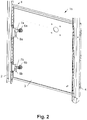
- Fig. 2 shows an interior view of an exemplary switch cabinet 1b, which also has a frame 2 and a door 3 that can be moved with the aid of hinges 4 relative to the frame 2.
- Two locks 6a, 6b are in turn attached to the door 3, each of which has a movable bolt 7a, 7b.
- the switchgear cabinet 1b comprises retaining elements 8a, 8b that are operatively connected to the bolts 7a, 7b, which cover the bolts 7a, 7b in the blocking position in an opening direction s of the door 3 and thus prevent the door 3 from opening.
- the bars 7a, 7b are specifically made of steel. However, they can also consist of a different material, in particular a material with a relatively low modulus of elasticity. For example, aluminum and plastics come into consideration, in particular fiber-reinforced plastics.
- FIG. 2 two different holding elements 8a, 8b are shown in order to make it clear that the invention is not tied to a specific shape of a holding element 8a, 8b.
- retaining elements 8a, 8b of the same type can also be used on a switchgear cabinet.
- the retaining element 8a is designed as a closed retaining bracket, the retaining element 8b as an open retaining bracket.
- the Fig. 3 shows the lock 6a with the bolt 7a and the retaining element 8a in a detailed view from the inside. It can be clearly seen that the holding element 8a has a closed holding bracket.
- the Fig. 4 shows the lock 6b with the bolt 7b and the retaining element 8b in a detailed view from the inside. It can be clearly seen that the holding element 8b has an open holding bracket.
- the Fig. 5 now shows a cross section through part of the control cabinet 1b.
- a seal 9 can be seen between the frame 2 and the door 3, which in the closed state pushes the door 3 slightly in the opening direction x.
- the bolt 7a is angled or cranked in this example, but it could in principle also be straight.
- the The bolt 7a also has a projection 10 which can be produced, for example, by bending or twisting the bolt 7a.
- the bolt 3 is slightly bent so that it also lies on a second locking surface B of the holding element 8a comes.
- the first locking surface A is arranged closer to the lock 6a, 6b than the second locking surface B, and the first locking surface A and the second locking surface B are oriented in opposite directions and are arranged on opposite sides of the bolt 7a in relation to the opening direction x of the door 3. This state is in the Fig. 6 shown.
- a switchgear cabinet 1a, 1b which comprises a frame 2, a door 3 that is movable with respect to the frame 2, a lock 6a, 6b with a movable bolt 7a, 7b and a retaining element 8a that is operatively connected to the bolt 7a, 7b, 8b, which covers the bolt 7a, 7b in its locked position in an opening direction of the door 3 and prevents the door 3 from opening.
- the bolt 7a, 7b located in a blocking position comes to rest on a first locking surface A and a second locking surface B of the holding element 8a, 8b when the door 3 is moved in the opening direction x.
- the first locking surface A is arranged closer to the lock 6a, 6b than the second locking surface B.
- the first locking surface A and the second locking surface B are oriented in opposite directions and are arranged on opposite sides of the bolt 7a, 7b in relation to the opening direction x of the door 3 .
- the switch cabinet 1a, 1b can also be described in such a way that it in turn comprises a frame 2, a door 3 that is movable relative to the frame, a lock 6a, 6b with a movable bolt 7a, 7b and one with the Bolt 7a, 7b operatively connected retaining element 8a, 8b, which covers the bolt 7a, 7b in its locked position in an opening direction x of the door 3 and prevents the door 3 from opening, the bolt 7a, 7b in a locked position when the door moves 3 comes to rest on a first locking surface A of the holding element 8a, 8b in the opening direction x, the bolt 7a, 7b protrudes beyond the first locking surface A in a direction pointing away from the lock 6a, 6b by a length a of at least 20 mm, a second locking surface B.
- the first locking surface A and the second locking surface B are oriented in opposite directions and are arranged on opposite sides of the bolt 7a, 7b in relation to the opening direction x of the door 3 and between the Latches 7a, 7b and the two locking surfaces A, B a maximum of 1 mm air b is provided.
- the air b denotes the total air between the bolt 7a, 7b and the two locking surfaces A, B. Since the bolt 7a in the Fig. 5 is applied to the first locking surface A, but the air b is only visible between the bolt 7a and the second locking surface B.
- the pressures, forces and torques that occur are also shown symbolically.
- the pressure p acting on the door 3 leads to a force Fc acting on the bolt 7a.
- the two forces Fa and Fb are applied to the two locking surfaces A and B.
- the torque Mc acts on the bolt 7a. Accordingly, a torque pointing in the opposite direction acts on the lock 6a.
- This can be implemented, for example, in that the bolt 7a is relatively stiff and / or is mounted in the lock 6a without play.
- only a small amount of force is required to close the switch cabinet 1b in this variant because of the air b.
- the limit value mentioned is at a pressure p 10 Pa.
- the effects according to the invention therefore occur at a very low pressure p, whereby the load on the frame 2, the door 3, the lock 6a, the bolt 7a and the retaining element 8a can be kept low.
- the torque Mc is particularly small in this embodiment. This can be achieved, for example, in that the bolt 7a has some play in its mounting and / or is relatively flexible. To achieve a bearing play, for example, the screw 11 can be loosened somewhat so that the bolt 7a can be pivoted practically without force about an axis normal to the plane of the drawing.
- the bolt 7a touches the first and second locking surfaces A, B in its locked position even when the switch cabinet interior N is depressurized.
- the bolt 7a is pretensioned so that the effects according to the invention take effect immediately when any internal pressure p occurs, whereby the load on the frame 2, the door 3, the lock 6a, the bolt 7a and the retaining element 8a can be further reduced .
- This can be achieved, for example, in that the door 3 is pressed correspondingly strongly outward by the seal 9 and that the bolt 7a has some play in its mounting and / or is relatively flexible.
- the bearing play can be achieved by loosening the screw 11.
- the cross section of the bolt 7a can be tapered in an area C between the lock 6a and the first locking surface A. In this way, too, the transmission of torque from the bolt 7a to the lock 6a can be kept low.
- the taper can be formed, for example, by a notch 12 in the bolt 7a, which is preferably provided close to the lock 6a, as is the case in FIG Fig. 7 is shown.
- the (center) distance c between notch 12 and lock 6a is less than 10 mm.
- the notch 12 lies in particular in that bending plane which, when subjected to a pressure load the door 3 is effective. In the specific example, the bending plane mentioned is aligned normal to the plane of the drawing and vertically.
- the bolt 7a can also be rotatably connected to the lock 6a about an axis 13 oriented transversely to the opening direction x of the door 3. In this way, torque transmission from the bolt 7a to the lock 6a can be completely excluded except for negligible bearing forces. Only tensile or compressive forces are thus transmitted to the lock 6a. Deformation of the door 3 or the frame 2 in which the lock 6a is installed is therefore particularly small. In particular, the (center) distance c between the axis 13 and lock 6a is again less than 10 mm.
- a bending load on the door 3 in the area of the lock 6a can be kept small or even avoided entirely. Instead, this area is predominantly or exclusively subjected to shear or tension. In this way, strong deformation of the door 3 in the area of the lock 6a or the lock 6a being torn out of the door 3, even at high pressures p occurring in the switch cabinet interior N, can be avoided. Furthermore, the reduced bending load on the bolt 7a prevents it from slipping out of the holding element 8a.
- the proposed measures can also keep the number of locks 6a, 6b used low, so that both the manufacture of the control cabinet 1a, 1b and the locking and opening of the control cabinet 1a, 1b are comparatively simple. Overall, thanks to the proposed measures, the switchgear cabinet 1a, 1b can withstand high pressures p despite its comparatively simple structure and fragile construction.
- This fastening area is also relatively lightly stressed by the proposed measures. That is, a bending load on the frame 2 in the area of the holding element 8a can be kept small or even avoided entirely. Instead, this area is also predominantly or exclusively subjected to shear or tension, which results in a strong deformation of the frame 2 in the Area of the holding element 8a or a tearing of the holding element 8a from the frame 2 is avoided.
- the embodiment variant shown is the lock 6a on the door 3 and the retaining element on the 8a frame 2 of the switch cabinet 1b, and the first locking surface A faces into the switch cabinet interior N and the second locking face B faces away from the switch cabinet interior N.
- the door 3 can optionally be opened by pulling the lock 6a or the key. The operation of the door 3 is therefore particularly intuitive.
- the lock 6 is arranged on the frame 2 and the retaining element 8 on the door 3 of the control cabinet 1a, 1b and the first locking surface A faces away from a switch cabinet interior N and the second locking surface B faces the switch cabinet interior N, see above like that in the Fig. 9 is shown.
- the lock 6 can optionally be attached to the frame 2 of the control cabinet 1a, 1b, which is generally more rigid than the door 3. The risk of the frame 2 being deformed in the area of the lock 6 is therefore particularly low.
- the bolt 7a, 7b has a cross section with a height of 15-35 mm and a thickness of 2-10 mm, the thickness being oriented in the opening direction x of the door 3 and the height being oriented at right angles thereto.
- the bolt 7a, 7b has an axial moment of resistance about an axis oriented in the vertical direction of 10-60 mm 3 .
- the bolt 7a, 7b is suitable for most of the loads occurring in a switch cabinet 1a, 1b.
- Fig. 11 and 12th show an embodiment of a door lock according to the invention, Fig. 11 in oblique view and Fig. 12 on average.
- the first locking surface A faces one another as seen in an axis of rotation of the bolt 7 angularly arranged straight sections D, E, which approximate a spiral shape.
- the distance between a point of contact of the bolt 7 with the first locking surface A and the lock 6 increases when the bolt 7 moves from a blocking position into an open position.
- the first locking surface A opens in a wedge shape, or the point of contact of the bolt 7 with the first locking surface A moves inward when the door 3 is locked.
- this relates to an embodiment variant in which the bolt 7 touches both the first locking surface A and the second locking surface B even at low pressure p in the switch cabinet interior N and the bolt 7 is pretensioned accordingly.
- the force required to pretension the bolt 7 is gradually built up when the bolt 7 is turned into the closed position.
- the torque Mc acting from the bolt 7 in the closed position on the lock 6 is low (cf. Fig. 6 ).
- the size of the holding element 8 can be kept small because of the special shape of the locking surface A, which makes this design particularly suitable for confined spaces. Specifically, this shows in the Fig. 11 The holding element 8 shown has only a small overall height.
- FIGS 13 and 14 finally show another embodiment of a door lock, Fig. 13 in front view and Fig. 14 in side view.
- the holding element 8 or the first locking surface A is moved particularly close to the lock 6. Accordingly, a torque Mc acting on the bolt 7 is particularly small, which leads to the advantages already described.
- first locking surface A can be beveled, as in FIG Fig. 14 is shown to allow easy locking of the door 3.
- the bolt 7 and the second locking surface B can be beveled, as in FIG Fig. 4 is realized by the run-in bevel 14.
- a bending load on the door 3 and the frame 3 in the area of the lock 6, 6a, 6b or retaining element 8, 8a, 8b is reduced or even avoided entirely by the proposed measures. This can result in severe deformation of the door 3 and the frame 3 in the area of the lock 6, 6a, 6b or retaining element 8, 8a, 8b or the lock 6, 6a, 6b or retaining element 8, 8a, 8b from the door 3 or the frame 2 can also be avoided in the case of high pressures p occurring in the switch cabinet interior N. Furthermore, the reduced bending load on the bolt 7, 7a, 7b also prevents the bolt from slipping out of the holding element 8, 8a, 8b.
- the number of locks 6, 6a, 6b used can be kept low by the proposed measures, whereby both the manufacture of the control cabinet 1a, 1b and the locking and opening of the control cabinet 1a, 1b is comparatively simple.
- the switchgear cabinet 1a, 1b can withstand high pressures p despite its comparatively simple structure and fragile construction.
- the invention is suitable for an electrical switch cabinet 1a, 1b, that is to say a switch cabinet 1a, 1b with electrical devices, for example switchgear.
- switchgear cabinet 1a, 1b or its components are not necessarily shown to scale and can therefore also have other proportions. Furthermore, the switchgear cabinet 1a, 1b can also include more or fewer components than shown.
Landscapes
- Engineering & Computer Science (AREA)
- Power Engineering (AREA)
- Structural Engineering (AREA)
- Casings For Electric Apparatus (AREA)
- Patch Boards (AREA)
- Switch Cases, Indication, And Locking (AREA)
Claims (10)
- Armoire de commande (1a, 1b), comprenant- un cadre (2),- une porte (3) mobile par rapport au cadre (2),- une serrure (6, 6a, 6b) comportant un pêne (7, 7a, 7b) monté de manière rotative à l'intérieur de celle-ci et- un élément de maintien (8, 8a, 8b) relié de manière fonctionnelle au pêne (7, 7a, 7b), qui recouvre le pêne (7, 7a, 7b) dans sa position de blocage dans un sens d'ouverture de la porte (3) et empêche une ouverture de la porte (3), dans laquelle- le pêne (7, 7a, 7b) se trouvant dans une position de blocage venant se placer sur une première surface de verrouillage (A) et une seconde surface de verrouillage (B) de l'élément de maintien (8, 8a, 8b) lors d'un mouvement de la porte (3) dans le sens d'ouverture (x),- la première surface de verrouillage (A) est disposée plus près de la serrure (6, 6a, 6b) que la seconde surface de verrouillage (B) et- la première surface de verrouillage (A) et la seconde surface de verrouillage (B) sont orientées dans des directions opposées et sont disposées sur des côtés opposés du pêne (7, 7a, 7b) par rapport au sens d'ouverture (x) de la porte (3), caractérisée en ce que- la première surface de verrouillage (A) et/ou la seconde surfaces de verrouillage (B) s'étendent en spirale lorsqu'elles sont vues dans un axe de rotation du pêne (7, 7a, 7b) ou présentent des sections droites (D, E) disposées à un angle l'une par rapport à l'autre, lesquelles se rapprochent d'une forme de spirale.
- Armoire de commande (1a, 1b) selon la revendication 1, caractérisée en ce que- la serrure (6, 6a, 6b) est disposée sur la porte (3) et l'élément de maintien (8, 8a, 8b) est disposé sur le cadre (2) de l'armoire de commande (1a, 1b) et- la première surface de verrouillage (A) de l'élément de maintien (8, 8a, 8b) est tournée vers un intérieur de l'armoire de commande (N) et la seconde surface de verrouillage (B) de l'élément de maintien (8, 8a, 8b) est tournée à l'opposé de l'intérieur de l'armoire de commande (N).
- Armoire de commande (1a, 1b) selon la revendication 1, caractérisée en ce que- la serrure (6, 6a, 6b) est disposée sur le cadre (2) et l'élément de maintien (8, 8a, 8b) est disposé sur la porte (3) de l'armoire de commande (1a, 1b) et- la première surface de verrouillage (A) de l'élément de maintien (8, 8a, 8b) est tournée à l'opposé d'un intérieur de l'armoire de commande (N) et la seconde surface de verrouillage (B) de l'élément de maintien (8, 8a, 8b) est tournée vers l'intérieur de l'armoire de commande (N).
- Armoire de commande (1a, 1b) selon l'une des revendications 1 à 3, caractérisée en ce que le pêne (7, 7a, 7b) est en contact avec les première et seconde surfaces de verrouillage (A, B) dans sa position de blocage au-dessus d'une valeur limite d'une pression (p) inférieure ou égale à 10 Pa et agissant dans l'intérieur de l'armoire de commande (N) et de manière égale sur la porte (3).
- Armoire de commande (1a, 1b) selon la revendication 4, caractérisée en ce que le pêne (7, 7a, 7b) est en contact avec les première et seconde surfaces de verrouillage (A, B) dans sa position de blocage lorsque l'intérieur de l'armoire de commande (N) est sans pression.
- Armoire de commande (1a, 1b) selon l'une des revendications 1 à 3, caractérisée en ce que le pêne (7, 7a, 7b) est en contact avec les première et seconde surfaces de verrouillage (A, B) dans sa position de blocage au-dessus d'une valeur limite d'une pression (p) supérieure ou égale à 100 Pa et agissant dans l'intérieur de l'armoire de commande (N) et de manière égale sur la porte (3).
- Armoire de commande (1a, 1b) selon l'une des revendications 1 à 6, caractérisée en ce que le pêne (7, 7a, 7b) présente une section transversale d'une hauteur de 15 à 35 mm et d'une épaisseur de 2 à 10 mm, dans laquelle l'épaisseur est orientée dans le sens d'ouverture (x) de la porte (3) et de manière perpendiculaire par rapport à la hauteur.
- Armoire de commande (1a, 1b) selon l'une des revendications 1 à 7, caractérisée en ce que le pêne (7, 7a, 7b) présente un couple de résistance axial autour d'un axe orienté dans la direction verticale de 10 à 60 mm3.
- Armoire de commande (1a, 1b) selon l'une des revendications 1 à 8, caractérisée en ce que le pêne (7, 7a, 7b) est relié de manière rotative à la serrure (6, 6a, 6b) autour d'un axe (13) orienté de manière transversale par rapport au sens d'ouverture (x) de la porte (3).
- Armoire de commande (1a, 1b) selon l'une des revendications 1 à 9, caractérisée en ce que la section transversale du pêne (7, 7a, 7b) est effilée dans une zone (C) entre la serrure (6, 6a, 6b) et la première surface de verrouillage (A).
Priority Applications (1)
| Application Number | Priority Date | Filing Date | Title |
|---|---|---|---|
| PL18773419T PL3684992T3 (pl) | 2017-09-20 | 2018-09-19 | Szafa sterownicza z ulepszoną mechaniką zamykania |
Applications Claiming Priority (2)
| Application Number | Priority Date | Filing Date | Title |
|---|---|---|---|
| DE102017121787.8A DE102017121787A1 (de) | 2017-09-20 | 2017-09-20 | Schaltschrank mit verbesserter Schließmechanik |
| PCT/EP2018/075281 WO2019057739A1 (fr) | 2017-09-20 | 2018-09-19 | Armoire électrique avec mécanisme de fermeture amélioré |
Publications (2)
| Publication Number | Publication Date |
|---|---|
| EP3684992A1 EP3684992A1 (fr) | 2020-07-29 |
| EP3684992B1 true EP3684992B1 (fr) | 2021-09-08 |
Family
ID=63667911
Family Applications (1)
| Application Number | Title | Priority Date | Filing Date |
|---|---|---|---|
| EP18773419.9A Active EP3684992B1 (fr) | 2017-09-20 | 2018-09-19 | Armoire électrique avec mécanisme de fermeture amélioré |
Country Status (5)
| Country | Link |
|---|---|
| EP (1) | EP3684992B1 (fr) |
| DE (1) | DE102017121787A1 (fr) |
| PL (1) | PL3684992T3 (fr) |
| WO (1) | WO2019057739A1 (fr) |
| ZA (1) | ZA202001723B (fr) |
Families Citing this family (1)
| Publication number | Priority date | Publication date | Assignee | Title |
|---|---|---|---|---|
| US11447982B2 (en) | 2019-03-26 | 2022-09-20 | Raytheon Company | Multidirectional enclosure compression locking mechanism |
Family Cites Families (9)
| Publication number | Priority date | Publication date | Assignee | Title |
|---|---|---|---|---|
| DE556226C (de) * | 1932-08-05 | Johannes Heim | Schlossanordnung, die bei UEberdruck im verschlossenen Raum die Tuer selbsttaetig freigibt | |
| DE7712478U1 (de) * | 1977-04-21 | 1977-08-04 | Licentia Patent-Verwaltungs-Gmbh, 6000 Frankfurt | Tuerverschluss |
| DE4336203A1 (de) * | 1993-10-23 | 1995-05-11 | Loh Kg Rittal Werk | Schaltschrank mit einem Rahmengestell aus Rahmenschenkeln |
| DE19549110A1 (de) * | 1995-12-29 | 1997-07-03 | Schulte Schlagbaum Ag | Schloß mit Schließblech |
| DE20018281U1 (de) * | 2000-10-25 | 2002-03-07 | Ramsauer, Dieter, 42555 Velbert | Schließzylinder |
| ATE334283T1 (de) * | 2003-02-05 | 2006-08-15 | Vkr Holding As | Verriegelungssystem für fenster, türen oder dergleichen, verriegelungselement und schliessblech |
| DE202009010004U1 (de) * | 2009-07-23 | 2010-12-23 | Dirak Dieter Ramsauer Konstruktionselemente Gmbh | Drehverschluss |
| DE102012023087A1 (de) * | 2012-11-27 | 2014-05-28 | Hodapp Gmbh & Co. Kg | Verschlussvorrichtung |
| GB2522238A (en) * | 2014-01-18 | 2015-07-22 | Robert Ian Wallis | Emergency access bolt |
-
2017
- 2017-09-20 DE DE102017121787.8A patent/DE102017121787A1/de not_active Withdrawn
-
2018
- 2018-09-19 PL PL18773419T patent/PL3684992T3/pl unknown
- 2018-09-19 WO PCT/EP2018/075281 patent/WO2019057739A1/fr not_active Ceased
- 2018-09-19 EP EP18773419.9A patent/EP3684992B1/fr active Active
-
2020
- 2020-03-18 ZA ZA2020/01723A patent/ZA202001723B/en unknown
Also Published As
| Publication number | Publication date |
|---|---|
| DE102017121787A1 (de) | 2019-03-21 |
| ZA202001723B (en) | 2025-04-30 |
| EP3684992A1 (fr) | 2020-07-29 |
| PL3684992T3 (pl) | 2022-02-21 |
| WO2019057739A1 (fr) | 2019-03-28 |
Similar Documents
| Publication | Publication Date | Title |
|---|---|---|
| EP2085559B1 (fr) | Dispositif d'étanchéité abaissable | |
| EP1460211A2 (fr) | Serrure de véhicule automobile | |
| EP2474698B1 (fr) | Dispositif d'étanchéité doté d'un profil d'étanchéité et d'un mécanisme destiné au déplacement du profil d'étanchéité lors de l'actionnement du mécanisme | |
| DE102017129427B3 (de) | Scharnierverschluss | |
| EP2362041B1 (fr) | Verrouillage de protection contre les mines pour l'agencement sur des portes de véhicules militaires | |
| EP2682545B1 (fr) | Dispositif de fermeture pour une porte coulissante ou une fenêtre coulissante, et porte coulissante ou fenêtre coulissante | |
| EP2058461A2 (fr) | Crémone | |
| DE9415846U1 (de) | Stangenverschluß | |
| EP3684992B1 (fr) | Armoire électrique avec mécanisme de fermeture amélioré | |
| EP3026201B1 (fr) | Verrouillage supplementaire | |
| EP2113624A2 (fr) | Dispositif de fixation de porte ou de fenêtre | |
| EP3222801A1 (fr) | Verrou pour coffres-forts | |
| EP2784248A1 (fr) | Agencement d'engrenage pour une ferrure de bielle | |
| EP3516135B1 (fr) | Ferrure | |
| EP1647658B1 (fr) | Dispositif pour l'aménagement entre le cadre dormant d'une fenêtre ou porte et le bord de l'ouverture correspondante | |
| EP1892361A1 (fr) | Fenêtre ou porte de sécurité anti-effraction | |
| EP1493889B1 (fr) | Couvercle pour fermetures | |
| EP3725992B1 (fr) | Entraînement | |
| EP1538287B1 (fr) | Poignée extérieure de porte | |
| EP3266960A1 (fr) | Système comprenant un châssis dormant destiné à loger un cadre de vantail | |
| EP2453086B1 (fr) | Ferrure de crémone pour battant fixe de fenêtres ou de portes à deux vantaux sans montant médian | |
| EP2105558A2 (fr) | Serrure avec un agencement de sécurité | |
| EP2093356A2 (fr) | Clé dotée d'une tige améliorée | |
| EP3374581B1 (fr) | Gâche filante | |
| EP1790806B1 (fr) | Dispositif de verrouillage à poussoir |
Legal Events
| Date | Code | Title | Description |
|---|---|---|---|
| STAA | Information on the status of an ep patent application or granted ep patent |
Free format text: STATUS: UNKNOWN |
|
| STAA | Information on the status of an ep patent application or granted ep patent |
Free format text: STATUS: THE INTERNATIONAL PUBLICATION HAS BEEN MADE |
|
| PUAI | Public reference made under article 153(3) epc to a published international application that has entered the european phase |
Free format text: ORIGINAL CODE: 0009012 |
|
| STAA | Information on the status of an ep patent application or granted ep patent |
Free format text: STATUS: REQUEST FOR EXAMINATION WAS MADE |
|
| 17P | Request for examination filed |
Effective date: 20200320 |
|
| AK | Designated contracting states |
Kind code of ref document: A1 Designated state(s): AL AT BE BG CH CY CZ DE DK EE ES FI FR GB GR HR HU IE IS IT LI LT LU LV MC MK MT NL NO PL PT RO RS SE SI SK SM TR |
|
| AX | Request for extension of the european patent |
Extension state: BA ME |
|
| DAV | Request for validation of the european patent (deleted) | ||
| DAX | Request for extension of the european patent (deleted) | ||
| RIC1 | Information provided on ipc code assigned before grant |
Ipc: E05B 15/02 20060101ALI20210219BHEP Ipc: E05B 17/20 20060101AFI20210219BHEP Ipc: E05C 3/04 20060101ALN20210219BHEP Ipc: E05B 15/10 20060101ALN20210219BHEP Ipc: E05B 63/12 20060101ALI20210219BHEP Ipc: E05B 17/00 20060101ALN20210219BHEP Ipc: H02B 1/38 20060101ALI20210219BHEP Ipc: E05B 65/10 20060101ALN20210219BHEP Ipc: E05B 65/02 20060101ALI20210219BHEP |
|
| GRAP | Despatch of communication of intention to grant a patent |
Free format text: ORIGINAL CODE: EPIDOSNIGR1 |
|
| STAA | Information on the status of an ep patent application or granted ep patent |
Free format text: STATUS: GRANT OF PATENT IS INTENDED |
|
| INTG | Intention to grant announced |
Effective date: 20210406 |
|
| GRAS | Grant fee paid |
Free format text: ORIGINAL CODE: EPIDOSNIGR3 |
|
| GRAA | (expected) grant |
Free format text: ORIGINAL CODE: 0009210 |
|
| STAA | Information on the status of an ep patent application or granted ep patent |
Free format text: STATUS: THE PATENT HAS BEEN GRANTED |
|
| AK | Designated contracting states |
Kind code of ref document: B1 Designated state(s): AL AT BE BG CH CY CZ DE DK EE ES FI FR GB GR HR HU IE IS IT LI LT LU LV MC MK MT NL NO PL PT RO RS SE SI SK SM TR |
|
| REG | Reference to a national code |
Ref country code: GB Ref legal event code: FG4D Free format text: NOT ENGLISH |
|
| REG | Reference to a national code |
Ref country code: CH Ref legal event code: EP Ref country code: AT Ref legal event code: REF Ref document number: 1428739 Country of ref document: AT Kind code of ref document: T Effective date: 20210915 |
|
| REG | Reference to a national code |
Ref country code: DE Ref legal event code: R096 Ref document number: 502018007023 Country of ref document: DE |
|
| REG | Reference to a national code |
Ref country code: IE Ref legal event code: FG4D Free format text: LANGUAGE OF EP DOCUMENT: GERMAN |
|
| REG | Reference to a national code |
Ref country code: SE Ref legal event code: TRGR |
|
| REG | Reference to a national code |
Ref country code: NL Ref legal event code: FP |
|
| REG | Reference to a national code |
Ref country code: LT Ref legal event code: MG9D |
|
| PG25 | Lapsed in a contracting state [announced via postgrant information from national office to epo] |
Ref country code: LT Free format text: LAPSE BECAUSE OF FAILURE TO SUBMIT A TRANSLATION OF THE DESCRIPTION OR TO PAY THE FEE WITHIN THE PRESCRIBED TIME-LIMIT Effective date: 20210908 Ref country code: BG Free format text: LAPSE BECAUSE OF FAILURE TO SUBMIT A TRANSLATION OF THE DESCRIPTION OR TO PAY THE FEE WITHIN THE PRESCRIBED TIME-LIMIT Effective date: 20211208 Ref country code: NO Free format text: LAPSE BECAUSE OF FAILURE TO SUBMIT A TRANSLATION OF THE DESCRIPTION OR TO PAY THE FEE WITHIN THE PRESCRIBED TIME-LIMIT Effective date: 20211208 Ref country code: RS Free format text: LAPSE BECAUSE OF FAILURE TO SUBMIT A TRANSLATION OF THE DESCRIPTION OR TO PAY THE FEE WITHIN THE PRESCRIBED TIME-LIMIT Effective date: 20210908 Ref country code: HR Free format text: LAPSE BECAUSE OF FAILURE TO SUBMIT A TRANSLATION OF THE DESCRIPTION OR TO PAY THE FEE WITHIN THE PRESCRIBED TIME-LIMIT Effective date: 20210908 Ref country code: ES Free format text: LAPSE BECAUSE OF FAILURE TO SUBMIT A TRANSLATION OF THE DESCRIPTION OR TO PAY THE FEE WITHIN THE PRESCRIBED TIME-LIMIT Effective date: 20210908 Ref country code: FI Free format text: LAPSE BECAUSE OF FAILURE TO SUBMIT A TRANSLATION OF THE DESCRIPTION OR TO PAY THE FEE WITHIN THE PRESCRIBED TIME-LIMIT Effective date: 20210908 |
|
| PG25 | Lapsed in a contracting state [announced via postgrant information from national office to epo] |
Ref country code: LV Free format text: LAPSE BECAUSE OF FAILURE TO SUBMIT A TRANSLATION OF THE DESCRIPTION OR TO PAY THE FEE WITHIN THE PRESCRIBED TIME-LIMIT Effective date: 20210908 Ref country code: GR Free format text: LAPSE BECAUSE OF FAILURE TO SUBMIT A TRANSLATION OF THE DESCRIPTION OR TO PAY THE FEE WITHIN THE PRESCRIBED TIME-LIMIT Effective date: 20211209 |
|
| REG | Reference to a national code |
Ref country code: CH Ref legal event code: PL |
|
| REG | Reference to a national code |
Ref country code: BE Ref legal event code: MM Effective date: 20210930 |
|
| PG25 | Lapsed in a contracting state [announced via postgrant information from national office to epo] |
Ref country code: IS Free format text: LAPSE BECAUSE OF FAILURE TO SUBMIT A TRANSLATION OF THE DESCRIPTION OR TO PAY THE FEE WITHIN THE PRESCRIBED TIME-LIMIT Effective date: 20220108 Ref country code: SM Free format text: LAPSE BECAUSE OF FAILURE TO SUBMIT A TRANSLATION OF THE DESCRIPTION OR TO PAY THE FEE WITHIN THE PRESCRIBED TIME-LIMIT Effective date: 20210908 Ref country code: SK Free format text: LAPSE BECAUSE OF FAILURE TO SUBMIT A TRANSLATION OF THE DESCRIPTION OR TO PAY THE FEE WITHIN THE PRESCRIBED TIME-LIMIT Effective date: 20210908 Ref country code: RO Free format text: LAPSE BECAUSE OF FAILURE TO SUBMIT A TRANSLATION OF THE DESCRIPTION OR TO PAY THE FEE WITHIN THE PRESCRIBED TIME-LIMIT Effective date: 20210908 Ref country code: PT Free format text: LAPSE BECAUSE OF FAILURE TO SUBMIT A TRANSLATION OF THE DESCRIPTION OR TO PAY THE FEE WITHIN THE PRESCRIBED TIME-LIMIT Effective date: 20220110 Ref country code: EE Free format text: LAPSE BECAUSE OF FAILURE TO SUBMIT A TRANSLATION OF THE DESCRIPTION OR TO PAY THE FEE WITHIN THE PRESCRIBED TIME-LIMIT Effective date: 20210908 Ref country code: CZ Free format text: LAPSE BECAUSE OF FAILURE TO SUBMIT A TRANSLATION OF THE DESCRIPTION OR TO PAY THE FEE WITHIN THE PRESCRIBED TIME-LIMIT Effective date: 20210908 Ref country code: AL Free format text: LAPSE BECAUSE OF FAILURE TO SUBMIT A TRANSLATION OF THE DESCRIPTION OR TO PAY THE FEE WITHIN THE PRESCRIBED TIME-LIMIT Effective date: 20210908 |
|
| REG | Reference to a national code |
Ref country code: DE Ref legal event code: R097 Ref document number: 502018007023 Country of ref document: DE |
|
| PG25 | Lapsed in a contracting state [announced via postgrant information from national office to epo] |
Ref country code: MC Free format text: LAPSE BECAUSE OF FAILURE TO SUBMIT A TRANSLATION OF THE DESCRIPTION OR TO PAY THE FEE WITHIN THE PRESCRIBED TIME-LIMIT Effective date: 20210908 |
|
| PLBE | No opposition filed within time limit |
Free format text: ORIGINAL CODE: 0009261 |
|
| STAA | Information on the status of an ep patent application or granted ep patent |
Free format text: STATUS: NO OPPOSITION FILED WITHIN TIME LIMIT |
|
| PG25 | Lapsed in a contracting state [announced via postgrant information from national office to epo] |
Ref country code: LU Free format text: LAPSE BECAUSE OF NON-PAYMENT OF DUE FEES Effective date: 20210919 Ref country code: IE Free format text: LAPSE BECAUSE OF NON-PAYMENT OF DUE FEES Effective date: 20210919 Ref country code: DK Free format text: LAPSE BECAUSE OF FAILURE TO SUBMIT A TRANSLATION OF THE DESCRIPTION OR TO PAY THE FEE WITHIN THE PRESCRIBED TIME-LIMIT Effective date: 20210908 Ref country code: BE Free format text: LAPSE BECAUSE OF NON-PAYMENT OF DUE FEES Effective date: 20210930 |
|
| 26N | No opposition filed |
Effective date: 20220609 |
|
| PG25 | Lapsed in a contracting state [announced via postgrant information from national office to epo] |
Ref country code: SI Free format text: LAPSE BECAUSE OF FAILURE TO SUBMIT A TRANSLATION OF THE DESCRIPTION OR TO PAY THE FEE WITHIN THE PRESCRIBED TIME-LIMIT Effective date: 20210908 Ref country code: LI Free format text: LAPSE BECAUSE OF NON-PAYMENT OF DUE FEES Effective date: 20210930 Ref country code: CH Free format text: LAPSE BECAUSE OF NON-PAYMENT OF DUE FEES Effective date: 20210930 |
|
| PG25 | Lapsed in a contracting state [announced via postgrant information from national office to epo] |
Ref country code: FR Free format text: LAPSE BECAUSE OF NON-PAYMENT OF DUE FEES Effective date: 20211108 |
|
| PG25 | Lapsed in a contracting state [announced via postgrant information from national office to epo] |
Ref country code: IT Free format text: LAPSE BECAUSE OF FAILURE TO SUBMIT A TRANSLATION OF THE DESCRIPTION OR TO PAY THE FEE WITHIN THE PRESCRIBED TIME-LIMIT Effective date: 20210908 |
|
| P01 | Opt-out of the competence of the unified patent court (upc) registered |
Effective date: 20230521 |
|
| PG25 | Lapsed in a contracting state [announced via postgrant information from national office to epo] |
Ref country code: CY Free format text: LAPSE BECAUSE OF FAILURE TO SUBMIT A TRANSLATION OF THE DESCRIPTION OR TO PAY THE FEE WITHIN THE PRESCRIBED TIME-LIMIT Effective date: 20210908 |
|
| PG25 | Lapsed in a contracting state [announced via postgrant information from national office to epo] |
Ref country code: HU Free format text: LAPSE BECAUSE OF FAILURE TO SUBMIT A TRANSLATION OF THE DESCRIPTION OR TO PAY THE FEE WITHIN THE PRESCRIBED TIME-LIMIT; INVALID AB INITIO Effective date: 20180919 |
|
| PG25 | Lapsed in a contracting state [announced via postgrant information from national office to epo] |
Ref country code: MK Free format text: LAPSE BECAUSE OF FAILURE TO SUBMIT A TRANSLATION OF THE DESCRIPTION OR TO PAY THE FEE WITHIN THE PRESCRIBED TIME-LIMIT Effective date: 20210908 |
|
| PG25 | Lapsed in a contracting state [announced via postgrant information from national office to epo] |
Ref country code: MT Free format text: LAPSE BECAUSE OF FAILURE TO SUBMIT A TRANSLATION OF THE DESCRIPTION OR TO PAY THE FEE WITHIN THE PRESCRIBED TIME-LIMIT Effective date: 20210908 |
|
| REG | Reference to a national code |
Ref country code: AT Ref legal event code: MM01 Ref document number: 1428739 Country of ref document: AT Kind code of ref document: T Effective date: 20230919 |
|
| PG25 | Lapsed in a contracting state [announced via postgrant information from national office to epo] |
Ref country code: AT Free format text: LAPSE BECAUSE OF NON-PAYMENT OF DUE FEES Effective date: 20230919 |
|
| PG25 | Lapsed in a contracting state [announced via postgrant information from national office to epo] |
Ref country code: AT Free format text: LAPSE BECAUSE OF NON-PAYMENT OF DUE FEES Effective date: 20230919 |
|
| PGFP | Annual fee paid to national office [announced via postgrant information from national office to epo] |
Ref country code: NL Payment date: 20250820 Year of fee payment: 8 |
|
| PGFP | Annual fee paid to national office [announced via postgrant information from national office to epo] |
Ref country code: DE Payment date: 20250820 Year of fee payment: 8 |
|
| PGFP | Annual fee paid to national office [announced via postgrant information from national office to epo] |
Ref country code: PL Payment date: 20250820 Year of fee payment: 8 |
|
| PGFP | Annual fee paid to national office [announced via postgrant information from national office to epo] |
Ref country code: GB Payment date: 20250820 Year of fee payment: 8 |
|
| PGFP | Annual fee paid to national office [announced via postgrant information from national office to epo] |
Ref country code: SE Payment date: 20250820 Year of fee payment: 8 |
|
| PG25 | Lapsed in a contracting state [announced via postgrant information from national office to epo] |
Ref country code: TR Free format text: LAPSE BECAUSE OF FAILURE TO SUBMIT A TRANSLATION OF THE DESCRIPTION OR TO PAY THE FEE WITHIN THE PRESCRIBED TIME-LIMIT Effective date: 20210908 |
|
| PGFP | Annual fee paid to national office [announced via postgrant information from national office to epo] |
Ref country code: AT Payment date: 20260410 Year of fee payment: 5 |