EP3686523A1 - Kühlschrank - Google Patents
Kühlschrank Download PDFInfo
- Publication number
- EP3686523A1 EP3686523A1 EP17926055.9A EP17926055A EP3686523A1 EP 3686523 A1 EP3686523 A1 EP 3686523A1 EP 17926055 A EP17926055 A EP 17926055A EP 3686523 A1 EP3686523 A1 EP 3686523A1
- Authority
- EP
- European Patent Office
- Prior art keywords
- temperature
- compressor
- storage compartment
- operational
- cooler
- Prior art date
- Legal status (The legal status is an assumption and is not a legal conclusion. Google has not performed a legal analysis and makes no representation as to the accuracy of the status listed.)
- Withdrawn
Links
Images






Classifications
-
- F—MECHANICAL ENGINEERING; LIGHTING; HEATING; WEAPONS; BLASTING
- F25—REFRIGERATION OR COOLING; COMBINED HEATING AND REFRIGERATION SYSTEMS; HEAT PUMP SYSTEMS; MANUFACTURE OR STORAGE OF ICE; LIQUEFACTION SOLIDIFICATION OF GASES
- F25B—REFRIGERATION MACHINES, PLANTS OR SYSTEMS; COMBINED HEATING AND REFRIGERATION SYSTEMS; HEAT PUMP SYSTEMS
- F25B49/00—Arrangement or mounting of control or safety devices
- F25B49/02—Arrangement or mounting of control or safety devices for compression type machines, plants or systems
-
- F—MECHANICAL ENGINEERING; LIGHTING; HEATING; WEAPONS; BLASTING
- F25—REFRIGERATION OR COOLING; COMBINED HEATING AND REFRIGERATION SYSTEMS; HEAT PUMP SYSTEMS; MANUFACTURE OR STORAGE OF ICE; LIQUEFACTION SOLIDIFICATION OF GASES
- F25B—REFRIGERATION MACHINES, PLANTS OR SYSTEMS; COMBINED HEATING AND REFRIGERATION SYSTEMS; HEAT PUMP SYSTEMS
- F25B41/00—Fluid-circulation arrangements
- F25B41/30—Expansion means; Dispositions thereof
- F25B41/31—Expansion valves
- F25B41/34—Expansion valves with the valve member being actuated by electric means, e.g. by piezoelectric actuators
-
- F—MECHANICAL ENGINEERING; LIGHTING; HEATING; WEAPONS; BLASTING
- F25—REFRIGERATION OR COOLING; COMBINED HEATING AND REFRIGERATION SYSTEMS; HEAT PUMP SYSTEMS; MANUFACTURE OR STORAGE OF ICE; LIQUEFACTION SOLIDIFICATION OF GASES
- F25B—REFRIGERATION MACHINES, PLANTS OR SYSTEMS; COMBINED HEATING AND REFRIGERATION SYSTEMS; HEAT PUMP SYSTEMS
- F25B41/00—Fluid-circulation arrangements
- F25B41/30—Expansion means; Dispositions thereof
- F25B41/37—Capillary tubes
- F25B41/375—Capillary tubes characterised by a variable restriction, e.g. restrictors made of shape memory alloy
-
- F—MECHANICAL ENGINEERING; LIGHTING; HEATING; WEAPONS; BLASTING
- F25—REFRIGERATION OR COOLING; COMBINED HEATING AND REFRIGERATION SYSTEMS; HEAT PUMP SYSTEMS; MANUFACTURE OR STORAGE OF ICE; LIQUEFACTION SOLIDIFICATION OF GASES
- F25B—REFRIGERATION MACHINES, PLANTS OR SYSTEMS; COMBINED HEATING AND REFRIGERATION SYSTEMS; HEAT PUMP SYSTEMS
- F25B41/00—Fluid-circulation arrangements
- F25B41/30—Expansion means; Dispositions thereof
- F25B41/385—Dispositions with two or more expansion means arranged in parallel on a refrigerant line leading to the same evaporator
-
- F—MECHANICAL ENGINEERING; LIGHTING; HEATING; WEAPONS; BLASTING
- F25—REFRIGERATION OR COOLING; COMBINED HEATING AND REFRIGERATION SYSTEMS; HEAT PUMP SYSTEMS; MANUFACTURE OR STORAGE OF ICE; LIQUEFACTION SOLIDIFICATION OF GASES
- F25D—REFRIGERATORS; COLD ROOMS; ICE-BOXES; COOLING OR FREEZING APPARATUS NOT OTHERWISE PROVIDED FOR
- F25D17/00—Arrangements for circulating cooling fluids; Arrangements for circulating gas, e.g. air, within refrigerated spaces
- F25D17/04—Arrangements for circulating cooling fluids; Arrangements for circulating gas, e.g. air, within refrigerated spaces for circulating air, e.g. by convection
- F25D17/06—Arrangements for circulating cooling fluids; Arrangements for circulating gas, e.g. air, within refrigerated spaces for circulating air, e.g. by convection by forced circulation
-
- F—MECHANICAL ENGINEERING; LIGHTING; HEATING; WEAPONS; BLASTING
- F25—REFRIGERATION OR COOLING; COMBINED HEATING AND REFRIGERATION SYSTEMS; HEAT PUMP SYSTEMS; MANUFACTURE OR STORAGE OF ICE; LIQUEFACTION SOLIDIFICATION OF GASES
- F25D—REFRIGERATORS; COLD ROOMS; ICE-BOXES; COOLING OR FREEZING APPARATUS NOT OTHERWISE PROVIDED FOR
- F25D17/00—Arrangements for circulating cooling fluids; Arrangements for circulating gas, e.g. air, within refrigerated spaces
- F25D17/04—Arrangements for circulating cooling fluids; Arrangements for circulating gas, e.g. air, within refrigerated spaces for circulating air, e.g. by convection
- F25D17/06—Arrangements for circulating cooling fluids; Arrangements for circulating gas, e.g. air, within refrigerated spaces for circulating air, e.g. by convection by forced circulation
- F25D17/062—Arrangements for circulating cooling fluids; Arrangements for circulating gas, e.g. air, within refrigerated spaces for circulating air, e.g. by convection by forced circulation in household refrigerators
- F25D17/065—Arrangements for circulating cooling fluids; Arrangements for circulating gas, e.g. air, within refrigerated spaces for circulating air, e.g. by convection by forced circulation in household refrigerators with compartments at different temperatures
-
- F—MECHANICAL ENGINEERING; LIGHTING; HEATING; WEAPONS; BLASTING
- F25—REFRIGERATION OR COOLING; COMBINED HEATING AND REFRIGERATION SYSTEMS; HEAT PUMP SYSTEMS; MANUFACTURE OR STORAGE OF ICE; LIQUEFACTION SOLIDIFICATION OF GASES
- F25D—REFRIGERATORS; COLD ROOMS; ICE-BOXES; COOLING OR FREEZING APPARATUS NOT OTHERWISE PROVIDED FOR
- F25D29/00—Arrangement or mounting of control or safety devices
-
- F—MECHANICAL ENGINEERING; LIGHTING; HEATING; WEAPONS; BLASTING
- F25—REFRIGERATION OR COOLING; COMBINED HEATING AND REFRIGERATION SYSTEMS; HEAT PUMP SYSTEMS; MANUFACTURE OR STORAGE OF ICE; LIQUEFACTION SOLIDIFICATION OF GASES
- F25B—REFRIGERATION MACHINES, PLANTS OR SYSTEMS; COMBINED HEATING AND REFRIGERATION SYSTEMS; HEAT PUMP SYSTEMS
- F25B2500/00—Problems to be solved
- F25B2500/19—Calculation of parameters
-
- F—MECHANICAL ENGINEERING; LIGHTING; HEATING; WEAPONS; BLASTING
- F25—REFRIGERATION OR COOLING; COMBINED HEATING AND REFRIGERATION SYSTEMS; HEAT PUMP SYSTEMS; MANUFACTURE OR STORAGE OF ICE; LIQUEFACTION SOLIDIFICATION OF GASES
- F25B—REFRIGERATION MACHINES, PLANTS OR SYSTEMS; COMBINED HEATING AND REFRIGERATION SYSTEMS; HEAT PUMP SYSTEMS
- F25B2600/00—Control issues
- F25B2600/02—Compressor control
- F25B2600/025—Compressor control by controlling speed
- F25B2600/0251—Compressor control by controlling speed with on-off operation
-
- F—MECHANICAL ENGINEERING; LIGHTING; HEATING; WEAPONS; BLASTING
- F25—REFRIGERATION OR COOLING; COMBINED HEATING AND REFRIGERATION SYSTEMS; HEAT PUMP SYSTEMS; MANUFACTURE OR STORAGE OF ICE; LIQUEFACTION SOLIDIFICATION OF GASES
- F25B—REFRIGERATION MACHINES, PLANTS OR SYSTEMS; COMBINED HEATING AND REFRIGERATION SYSTEMS; HEAT PUMP SYSTEMS
- F25B2600/00—Control issues
- F25B2600/11—Fan speed control
- F25B2600/112—Fan speed control of evaporator fans
-
- F—MECHANICAL ENGINEERING; LIGHTING; HEATING; WEAPONS; BLASTING
- F25—REFRIGERATION OR COOLING; COMBINED HEATING AND REFRIGERATION SYSTEMS; HEAT PUMP SYSTEMS; MANUFACTURE OR STORAGE OF ICE; LIQUEFACTION SOLIDIFICATION OF GASES
- F25B—REFRIGERATION MACHINES, PLANTS OR SYSTEMS; COMBINED HEATING AND REFRIGERATION SYSTEMS; HEAT PUMP SYSTEMS
- F25B2600/00—Control issues
- F25B2600/25—Control of valves
- F25B2600/2513—Expansion valves
-
- F—MECHANICAL ENGINEERING; LIGHTING; HEATING; WEAPONS; BLASTING
- F25—REFRIGERATION OR COOLING; COMBINED HEATING AND REFRIGERATION SYSTEMS; HEAT PUMP SYSTEMS; MANUFACTURE OR STORAGE OF ICE; LIQUEFACTION SOLIDIFICATION OF GASES
- F25B—REFRIGERATION MACHINES, PLANTS OR SYSTEMS; COMBINED HEATING AND REFRIGERATION SYSTEMS; HEAT PUMP SYSTEMS
- F25B2700/00—Sensing or detecting of parameters; Sensors therefor
- F25B2700/21—Temperatures
- F25B2700/2104—Temperatures of an indoor room or compartment
-
- F—MECHANICAL ENGINEERING; LIGHTING; HEATING; WEAPONS; BLASTING
- F25—REFRIGERATION OR COOLING; COMBINED HEATING AND REFRIGERATION SYSTEMS; HEAT PUMP SYSTEMS; MANUFACTURE OR STORAGE OF ICE; LIQUEFACTION SOLIDIFICATION OF GASES
- F25B—REFRIGERATION MACHINES, PLANTS OR SYSTEMS; COMBINED HEATING AND REFRIGERATION SYSTEMS; HEAT PUMP SYSTEMS
- F25B2700/00—Sensing or detecting of parameters; Sensors therefor
- F25B2700/21—Temperatures
- F25B2700/2117—Temperatures of an evaporator
-
- F—MECHANICAL ENGINEERING; LIGHTING; HEATING; WEAPONS; BLASTING
- F25—REFRIGERATION OR COOLING; COMBINED HEATING AND REFRIGERATION SYSTEMS; HEAT PUMP SYSTEMS; MANUFACTURE OR STORAGE OF ICE; LIQUEFACTION SOLIDIFICATION OF GASES
- F25D—REFRIGERATORS; COLD ROOMS; ICE-BOXES; COOLING OR FREEZING APPARATUS NOT OTHERWISE PROVIDED FOR
- F25D2600/00—Control issues
- F25D2600/04—Controlling heat transfer
-
- F—MECHANICAL ENGINEERING; LIGHTING; HEATING; WEAPONS; BLASTING
- F25—REFRIGERATION OR COOLING; COMBINED HEATING AND REFRIGERATION SYSTEMS; HEAT PUMP SYSTEMS; MANUFACTURE OR STORAGE OF ICE; LIQUEFACTION SOLIDIFICATION OF GASES
- F25D—REFRIGERATORS; COLD ROOMS; ICE-BOXES; COOLING OR FREEZING APPARATUS NOT OTHERWISE PROVIDED FOR
- F25D2700/00—Means for sensing or measuring; Sensors therefor
- F25D2700/12—Sensors measuring the inside temperature
-
- Y—GENERAL TAGGING OF NEW TECHNOLOGICAL DEVELOPMENTS; GENERAL TAGGING OF CROSS-SECTIONAL TECHNOLOGIES SPANNING OVER SEVERAL SECTIONS OF THE IPC; TECHNICAL SUBJECTS COVERED BY FORMER USPC CROSS-REFERENCE ART COLLECTIONS [XRACs] AND DIGESTS
- Y02—TECHNOLOGIES OR APPLICATIONS FOR MITIGATION OR ADAPTATION AGAINST CLIMATE CHANGE
- Y02B—CLIMATE CHANGE MITIGATION TECHNOLOGIES RELATED TO BUILDINGS, e.g. HOUSING, HOUSE APPLIANCES OR RELATED END-USER APPLICATIONS
- Y02B30/00—Energy efficient heating, ventilation or air conditioning [HVAC]
- Y02B30/70—Efficient control or regulation technologies, e.g. for control of refrigerant flow, motor or heating
Definitions
- the present invention relates to a refrigeration machine, particularly, control of a cooler fan and an expansion valve in the refrigeration machine when starting and stopping an operation of a compressor.
- Patent Literature 1 Japanese Patent Laying-Open No. 2011-27325 (Patent Literature 1) describes a refrigerator configured to control a temperature of the storage compartment by rotating a cooler fan when the compressor is non-operational.
- the refrigerator described in Japanese Patent Laying-Open No. 2011-27325 can cool the storage compartment without motive power of the compressor by using the cooler having a low temperature after the compressor becomes non-operational. Therefore, a time interval until the operation of the compressor is restarted due to an increased temperature of the storage compartment can be long, thereby providing an effect of reducing an average amount of consumption of power in both operational and non-operational states of the refrigerator.
- PTL 1 Japanese Patent Laying-Open No. 2011-27325
- the present invention has been made to solve the foregoing problem, and has an object to provide a refrigeration machine that can suppress increase in temperature of a storage compartment and can reduce an average amount of consumption of power even when a difference is small between a temperature of a cooler and the temperature of the storage compartment.
- a refrigeration machine includes: a refrigerant circuit in which a compressor, a condenser, an expansion device, and a cooler are connected by a refrigerant pipe; a first storage compartment configured to store a cooling target; a fan configured to send air from the cooler to the first storage compartment; a first temperature sensor configured to detect a temperature of the first storage compartment; and a second temperature sensor configured to detect a temperature of the cooler.
- the expansion device is configured to have a degree of opening settable to a fully closed state, and the degree of opening corresponds to the fully closed state while the compressor is non-operational.
- the fan is configured to continue to be operational while the compressor is non-operational and when a temperature difference obtained by subtracting a detection temperature of the second temperature sensor from a detection temperature of the first temperature sensor is larger than a first criterion value.
- the fan is configured to become non-operational when transition is made, while the compressor is non-operational, from a state in which the temperature difference is larger than the first criterion value to a state in which the temperature difference is smaller than the first criterion value.
- the fan is configured to be non-operational while the compressor is operational and when the temperature difference is smaller than a second criterion value.
- the fan is configured to become operational when transition is made, while the compressor is operational, from a state in which the temperature difference is smaller than the second criterion value to a state in which the temperature difference is larger than the second criterion value.
- the temperature of the storage compartment can be suppressed from being increased while the compressor is non-operational.
- the non-operational period of the compressor can be long.
- a refrigeration machine with a reduced average amount of consumption of power including power for turning on and off a compressor.
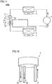
- Fig. 1 is a schematic view of a refrigeration cycle of a refrigeration machine according to a first embodiment.
- a refrigeration machine 100 includes: a compressor 1 changeable in rotating speed; a condenser 2; an expansion device 3; a cooler 4; a condenser fan 5; and a cooler fan 6.
- Compressor 1, condenser 2, expansion device 3, and cooler 4 are communicated via a refrigerant pipe to form a refrigeration cycle.
- an electronic expansion valve changeable in a degree of opening in accordance with a control signal can be used as expansion device 3, for example.
- Fig. 1 High-temperature high-pressure gas refrigerant discharged from compressor 1 passes through condenser 2 (for example, an air heat exchanger).
- condenser 2 for example, an air heat exchanger
- the refrigerant exchanges heat with external air around refrigeration machine 100, and the refrigerant is condensed by heat dissipation.
- the condensed high-pressure liquid refrigerant is decompressed by expansion device 3 and becomes low-pressure two-phase refrigerant.
- the refrigerant flows into cooler 4.
- cooler 4 heat is exchanged between the refrigerant and circulated air from the storage compartment.
- the circulated air from the storage compartment is cooled by the refrigerant, and the refrigerant becomes low-pressure gas refrigerant. Then, the refrigerant in the form of low-pressure gas flows into compressor 1, is fed with a pressure, and is then discharged again.
- Fig. 2 shows a first modification of the refrigeration cycle.
- an internal heat exchanger 11 may be provided to exchange heat with refrigerant in a pipe connected to the outlet of cooler 4 when decompressing the refrigerant in expansion device 3.
- the temperature at the inlet of expansion device 3 is higher than the temperature at the inlet of the suction pipe connected to compressor 1.
- the refrigerant after introduced into expansion device 3 is cooled by the refrigerant passing through the suction pipe connected to compressor 1. Accordingly, a degree of dryness at the inlet of cooler 4 has a value close to 0 and the refrigerant therefore has a large amount of liquid phase, whereby cooler 4 can be used effectively.
- Fig. 3 is a schematic view showing a refrigeration machine having one storage compartment.
- the refrigeration machine according to the first embodiment includes: a storage compartment 13 (any one of a vegetable compartment, a freezer compartment, and a cold compartment); the above-described refrigeration cycle; and temperature sensors 7, 8 respectively installed at storage compartment 13 and cooler 4.
- compressor 1, cooler fan 6, and expansion device 3 are controlled as described below.
- the installation locations of the sensors in Fig. 3 are exemplary, and are not limited.
- temperature sensor 7 may be installed at an upper portion of storage compartment 13 as long as temperature sensor 7 represents the temperature of storage compartment 13.
- temperature sensor 8 for the cooler may be installed at any location as long as temperature sensor 8 represents the temperature of the cooler, such as the center of cooler 4.
- a "normal operation mode” represents a state in which compressor 1 is driven, expansion device 3 is open and cooler fan 6 is driven to cool inside of storage compartment 13. A behavior in the normal operation mode will be described.
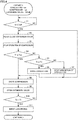
- Fig. 4 is a flowchart for illustrating control in the normal operation mode.
- a criterion temperature Toff for stopping the operation of compressor 1 is set.
- storage compartment temperature Tr becomes lower than Toff, further cooling is not required.
- control device 20 make transition to determine to stop the operation of compressor 1 (YES in step S1).
- control device 20 By stopping the operation of compressor 1 while maintaining pressures at high-pressure portion and low-pressure portion of the refrigeration cycle, loss can be reduced when restarting the operation of compressor 1. Moreover, by using cooler 4 having a low temperature, an amount of consumption of power can be reduced. Hence, control device 20 fully closes expansion device 3 (step S2), and stops the operation of compressor 1 (step S3).
- control device 20 continuously maintains compressor 1 to be non-operational with the inside of storage compartment 13 being maintained to be cool.
- control device 20 determines whether to continuously operate cooler fan 6 (step S5).
- control device 20 When cooler temperature Te is lower than storage compartment temperature Tr (YES in step S5), it can be determined that cooler 4 can be used to cool storage compartment 13. Hence, control device 20 operates only cooler fan 6 (step S6). On the other hand, when cooler temperature Te is higher than storage compartment temperature Tr (NO in step S5), it can be determined that cooler 4 cannot be used for cooling. Hence, control device 20 stops the operation of cooler fan 6 (step S7). After the processes of step S6 or step S7 are ended and the process of steps S2 and S3 are performed again, control device 20 determines again in step S4 whether to restart the operation of compressor 1.
- control device 20 drives compressor 1 (step S8) and opens expansion device 3 (step S9). Then, the pressure of the low-pressure portion is decreased gradually.
- control device 20 determines whether or not cooler temperature Te is higher than storage compartment temperature Tr (step S10). When cooler temperature Te is higher than storage compartment temperature Tr (NO in S10), it can be determined that cooler 4 is not sufficiently cooled, so that the determination of step S10 is performed again after performing the processes of steps S8 and S9. When cooler temperature Te is less than or equal to storage compartment temperature Tr (YES in S10), it can be determined that cooler 4 is sufficiently cooled. Hence, control device 20 drives cooler fan 6 having been non-operational, so as to send cool air to storage compartment 13 again.
- Fig. 5 is a waveform diagram showing a temperature change in a comparative example in which the expansion device is fixed to the open state.
- the expansion device In the control of the comparative example, the expansion device is open.
- the high-pressure refrigerant and the low-pressure refrigerant in the refrigeration cycle portion are readily mixed via expansion device 3. Therefore, temperature Te of the low-pressure refrigerant at the cooler 4 side is abruptly increased at a time t2.
- temperature Te of cooler 4 becomes more than or equal to storage compartment temperature Tr during a period of times t2 to t3 immediately after stopping the operation of the compressor.
- Fig. 6 is a waveform diagram showing a temperature change when the control of Fig. 4 of the first embodiment is performed.
- expansion device 3 is fully closed (time t11).
- time t11 By fully closing expansion device 3, the high-pressure refrigerant does not flow into the low-pressure side, whereby the low pressure can be maintained. Therefore, even when cooler fan 6 is maintained to be driven, air having a temperature more than or equal to the storage compartment temperature can be prevented from being supplied to storage compartment 13 for a while (times t11 to t12).
- cooler temperature Te When expansion device 3 is fully closed, cooler temperature Te is not increased abruptly, and the state of Tr>Te is maintained during the period of times t11 to t12. During this period, cooler fan 6 can be driven to cool storage compartment 13. However, by rotating cooler fan 6, air in storage compartment 13 warmed by food brought into storage compartment 13 and external air around storage compartment 13 flows into cooler 4. Accordingly, the liquid refrigerant is evaporated to gradually increase cooler temperature Te (times t11 to t12). The increase of cooler temperature Te leads to increase of storage compartment temperature Tr.
- cooler temperature Te coincides with storage compartment temperature Tr after passage of a certain period of time (time t12). In this state, storage compartment 13 cannot be cooled even though cooler fan 6 is driven, thus resulting in a meaningless operation. Hence, when Tr ⁇ Te is satisfied, the operation of cooler fan 6 is stopped (times t12 to t13).
- control device 20 restarts the operation of compressor 1 in order to cool storage compartment 13.
- cooler temperature Te is higher than storage compartment temperature Tr, cooler fan 6 is maintained to be non-operational (times t13 to t14). In this way, cooler temperature Te is decreased abruptly.
- cooler temperature Te When cooler temperature Te is decreased abruptly to satisfy Te ⁇ Tr, even if cooler fan 6 is driven, air in the cooler with a temperature less than or equal to storage compartment temperature Tr can be sent securely to the inside of storage compartment 13. Hence, cool air can be sent without increasing storage compartment temperature Tr.
- temperature sensors 7, 8 have variations and tolerances (margins) corresponding to the variations should be provided to the determination process.
- the condition of the determination in the process of step S5 of Fig. 4 is not limited to Tr ⁇ Te, and may be Tr-A ⁇ Te (where A is a predetermined value) in consideration of influences of the sensor variations.
- the condition of operating cooler fan 6 in step S10 of Fig. 4 is not limited to Te ⁇ Tr, and may be Te ⁇ Tr-B (where B is a predetermined value) in consideration of the influences of the sensor variations.
- Fig. 7 is a flowchart for a condition of stopping the operation of cooler fan 6 when compressor 1 is non-operational and a condition of driving cooler fan 6 after restarting the operation of compressor 1, in the case where the sensor variations are taken into consideration.
- the flowchart of Fig. 7 is different from the flowchart of Fig. 4 in that steps S5A, S10A are performed instead of steps S5, S10. Hence, steps S5A, S10A will be hereinafter described and the other parts will not be described repeatedly.
- step S5A control device 20 compares temperature Tr of storage compartment 13 with cooler temperature Te to determine whether to make cooler fan 6 operational or non-operational.
- tolerance A is provided in consideration of the variations of the temperature sensors.
- step S5A when Tr-A ⁇ Te is satisfied (YES in S5A), the process proceeds to step S6, whereas when Tr-A ⁇ Te is not satisfied (NO in S5A), the process proceeds to step S7.
- tolerance A By taking tolerance A into consideration, cooler fan 6 can become non-operational securely before storage compartment temperature Tr becomes higher than cooler temperature Te.
- step S10A after restarting the operation of compressor 1, control device 20 compares storage compartment temperature Tr with cooler temperature Te to determine whether to drive cooler fan 6. On this occasion, tolerance B is provided in consideration of the variations of temperature sensors 7, 8. When Te ⁇ Tr-B is not satisfied (NO in S10A), it is determined that the cooler is not sufficiently cooled. Hence, the process proceeds to step S8 and control device 20 maintains the non-operational state of cooler fan 6. When Te ⁇ Tr-B is satisfied, it is determined that cooler 4 is sufficiently cooled. Hence, the process proceeds to step S11 and control device 20 drives cooler fan 6 to send cool air to storage compartment 13.
- Fig. 8 is a waveform diagram showing a temperature change when the control of the flowchart of Fig. 7 is performed.
- a time t12A which corresponds to a timing to stop the operation of cooler fan 6, is close to time t11
- a time t14A which corresponds to a timing to restart the operation of cooler fan 6, is further away from time t13.
- cooler fan 6 can be securely prevented from being driven when cooler temperature Te is higher than storage compartment temperature Tr.
- a refrigeration cycle of the refrigeration machine according to the second embodiment is the same as that described in the first embodiment with reference to Fig. 1 or Fig. 2 , and therefore will not be described.
- the refrigeration machine according to the second embodiment has two or more storage compartments that can be set to different setting temperatures.
- Fig. 9 shows an exemplary configuration of a refrigeration machine having two storage compartments according to the second embodiment.
- a feature lies in that the temperature of a storage compartment 13B is higher than that of a storage compartment 13A.
- the temperature of storage compartment 13A is controlled by a damper 15 provided in an air path that connects between cooler 4 and storage compartment 13A.
- control device 20 opens or closes damper 15 in accordance with an output value of temperature sensor 7A of storage compartment 13A.
- damper 15 By opening damper 15, cooling air flows into storage compartment 13A, with the result that temperature TrA of storage compartment 13A is decreased.
- damper 15 By closing damper 15, the cooling air cannot flow into storage compartment 13A, with the result that temperature TrA of storage compartment 13A is increased due to transfer of heat from external air.
- control device 20 can adjust the temperature of storage compartment 13A by opening or closing damper 15 based on an output value of temperature sensor 7A.
- control device 20 adjusts the temperature of storage compartment 13B by controlling the frequency and ON-OFF of compressor 1 in accordance with an output value of temperature sensor 7B of storage compartment 13B.
- storage compartment temperature Tr described in the control flow diagram is also applicable to temperature TrB of storage compartment 13B in the second embodiment in which two or more storage compartments are provided.
- storage compartment temperature Tr of the control flow diagram (each of Fig. 4 and Fig. 7 ) as temperature TrB of storage compartment 13B, the temperature of storage compartment 13B having the low setting temperature can be prevented from being increased greatly from the setting temperature.
- Fig. 10 shows a modification representing a refrigeration machine having three storage compartments.
- the refrigeration machine shown in Fig. 10 includes storage compartments 13A to 13C.
- storage compartment 13A disposed at an upper stage is a cold compartment
- storage compartment 13B disposed at a middle stage is a freezer compartment
- storage compartment 13C disposed at the lower stage is a vegetable compartment.
- the setting temperature of storage compartment 13B is set to be lower than the setting temperatures of storage compartment 13A and storage compartment 13C.
- Compressor 1 and condenser 2 are disposed at the bottom portion and rear surface of storage compartment 13C
- cooler 4 and cooler fan 6 are disposed in an air path at the rear surface of storage compartment 13B.
- Fig. 11 is a schematic view of a refrigeration cycle of a refrigeration machine according to a third embodiment.
- a refrigeration machine 100B includes: a compressor 1 changeable in rotating speed; a condenser 2; an expansion device 3B; a cooler 4; a condenser fan 5; and a cooler fan 6.
- Compressor 1, condenser 2, expansion device 3B, and cooler 4 are communicated via a refrigerant pipe to form a refrigeration cycle.
- Expansion device 3B includes a flow path switching valve 9 and capillary tubes 31, 32.
- Expansion device 3B employs capillary tubes 31, 32, which are pipes having small diameters to provide a pressure difference. An amount of contraction of each of capillary tubes 31, 32 is fixed.
- Flow path switching valve 9 has one inlet-side flow path PI and two outlet-side flow paths P2, P3.
- Fig. 12 is a schematic view showing an external appearance of flow path switching valve 9.
- Fig. 13 shows a switching state of flow path switching valve 9. It should be noted that each of Fig. 12 and Fig. 13 shows an example in which two capillary tubes 31, 32 are connected to outlet-side flow paths P2, P3 of flow path switching valve 9, respectively; however, the number of the capillary tubes may be 1, 3, or more and is not limited to 2.
- Fig. 13 illustrates: a case where the refrigerant flows from inlet-side flow path PI to the two flow paths (P2+P3); the fully closed state of the expansion device in step S2 of the control flow diagram of each of Fig. 4 and Fig. 7 ; a case where the refrigerant flows from inlet-side flow path PI to outlet-side flow path P3; and a case where the refrigerant flows from inlet-side flow path PI to outlet-side flow path P2.
- an internal heat exchanger 11B may be provided to exchange heat between the refrigerant flowing in a pipe (which may be capillary tubes 31, 32) connected to the outlet of cooler 4 and the refrigerant to be suctioned by compressor 1, when decompressing the refrigerant in expansion device 3.
- a feature of a fourth embodiment lies in that compressor 1 is driven with expansion device 3 closed in the operation after compressor 1 becomes non-operational. By controlling compressor 1 and expansion device 3 in this way, pressure at the low pressure portion can be decreased abruptly, whereby cooler fan 6 can be driven promptly.
- Fig. 14 is a flowchart showing the control performed in the fourth embodiment.
- the process of opening the expansion valve in step S9 is omitted and a process of step S20 is added instead.
- control device 20 compares cooler temperature Te with storage compartment temperature Tr immediately in S10. When Te ⁇ Tr is satisfied in step S10, the process proceeds to step S20 to open expansion device 3.
- the other parts of the flowchart of Fig. 14 are the same as those of the flowchart of Fig. 4 , and therefore will not be described repeatedly.
- Fig. 15 is a waveform diagram showing a temperature change when the control of the flowchart of Fig. 14 is performed.
- compressor 1 is operated and expansion device 3 is controlled to be in the closed state during a period of times t13 to t14. By controlling in this way, pressure of the low-pressure portion connected to the suction side of compressor 1 can be decreased promptly.
- Fig. 16 is a schematic view showing a configuration of a refrigeration machine according to a fifth embodiment.
- the fifth embodiment represents an exemplary food showcase placed in a shop or the like.
- the configuration shown in each of Fig. 1, Fig. 2 , and Fig. 11 is applicable.
- the same effect as that in each of the first to fourth embodiments can be obtained by performing the control of each of Fig. 4 , Fig. 7 , and Fig. 14 .
- a refrigeration machine includes: a refrigerant circuit in which a compressor 1, a condenser 2, an expansion device 3, and a cooler 4 are connected by a refrigerant pipe; a first storage compartment 13 configured to store a cooling target; a fan 6 configured to send air from cooler 4 to first storage compartment 13; a first temperature sensor 7 configured to detect a temperature Tr of first storage compartment 13; and a second temperature sensor 8 configured to detect a temperature Te of cooler 4.
- Expansion device 3 is configured to have a degree of opening settable to a fully closed state, and the degree of opening corresponds to the fully closed state while compressor 1 is non-operational. As shown in S5 of Fig. 4 or S5A of Fig.
- fan 6 is configured to continue to be operational while compressor 1 is non-operational and when a temperature difference ⁇ T obtained by subtracting a detection temperature Te of second temperature sensor 8 from a detection temperature Tr of first temperature sensor 7 is larger than a first criterion value (0 or a tolerance A). Fan 6 is configured to become non-operational when transition is made, while compressor 1 is non-operational, from a state in which temperature difference ⁇ T is larger than the first criterion value to a state in which temperature difference ⁇ T is smaller than the first criterion value. As shown in S10 of Fig. 4 or S10A of Fig.
- fan 6 is configured to be non-operational while compressor 1 is operational and when temperature difference ⁇ T is smaller than a second criterion value (0 or a tolerance B). Fan 6 is configured to become operational when transition is made, while compressor 1 is operational, from a state in which temperature difference ⁇ T is smaller than the second criterion value to a state in which temperature difference ⁇ T is larger than the second criterion value.
- the refrigeration machine includes a plurality of storage compartments 13A to 13C.
- the first storage compartment is a storage compartment 13B having a lowest setting temperature among the plurality of storage compartments.
- expansion device 3 is an expansion valve changeable in degree of opening.
- expansion device 3B includes a capillary tube 31, 32, and a flow path switching valve 9 configured to open and close a refrigerant pipe (flow path P2, P3) communicating with capillary tube 31, 32.
- the refrigeration machine further includes an internal heat exchanger 11, 11B configured to exchange heat between refrigerant passing through expansion device 3, 3B and refrigerant in a suction pipe connected to compressor 1.
- an internal heat exchanger 11, 11B configured to exchange heat between refrigerant passing through expansion device 3, 3B and refrigerant in a suction pipe connected to compressor 1.
- expansion device 3 or 3B is configured to continue to be in the fully closed state during a period in which detection temperature Tr of first temperature sensor 7 is higher than detection temperature Te of second temperature sensor 8.
- the storage compartment temperature can be suppressed from being increased while compressor 1 is non-operational. Hence, a non-operational period of the compressor can be long. As a result, an average amount of consumption of power including power for turning on and off compressor 1 can be reduced.
- the difference between the high pressure of the refrigerant and the low pressure of the refrigerant can be maintained during the non-operational period of compressor 1.
- air having a temperature more than or equal to storage compartment temperature Tr can be prevented from being sent to the storage compartment by driving cooler fan 6 with cooler 4 having not been cooled yet immediately after restarting the operation of compressor 1.
- temperature Tr of the storage compartment can be prevented from being increased, whereby the temperature of food placed on the storage compartment can be prevented from being increased.
- quality of the food can be secured.
- the refrigeration machine provides an energy saving effect by causing cooler fan 6, expansion device 3, and compressor 1 to perform the series of operations in the order described above. For example, when cooler fan 6 is not operated in period Pd2 of t11 to t12 of Fig. 6 or t11 to t12A of Fig. 8 , warm air in the storage compartment does not reach cooler 4, with the result that temperature Te of cooler 4 does not become more than storage compartment temperature Tr.
- expansion device 3 when expansion device 3 is not fully closed in period Pd2 of t11 to t12 of Fig. 6 or t11 to t12A of Fig. 8 , the high pressure and the low pressure are immediately changed to be equal to each other just after compressor 1 becomes non-operational. Accordingly, cooler temperature Te becomes more than or equal to storage compartment temperature Tr. Hence, loss is caused due to the high pressure and the low pressure being changed to be equal to each other, thus resulting in decreased energy saving. Hence, energy saving is attained only by controlling compressor 1, cooler fan 6, and expansion device 3 in the series of flows described in order of periods Pd1 to Pd5 of each of Fig. 6 , Fig. 8 , and Fig. 15 .
Landscapes
- Engineering & Computer Science (AREA)
- Physics & Mathematics (AREA)
- Mechanical Engineering (AREA)
- Thermal Sciences (AREA)
- General Engineering & Computer Science (AREA)
- Chemical & Material Sciences (AREA)
- Combustion & Propulsion (AREA)
- Metallurgy (AREA)
- Devices That Are Associated With Refrigeration Equipment (AREA)
- Cold Air Circulating Systems And Constructional Details In Refrigerators (AREA)
Applications Claiming Priority (1)
| Application Number | Priority Date | Filing Date | Title |
|---|---|---|---|
| PCT/JP2017/033894 WO2019058450A1 (ja) | 2017-09-20 | 2017-09-20 | 冷凍機 |
Publications (2)
| Publication Number | Publication Date |
|---|---|
| EP3686523A1 true EP3686523A1 (de) | 2020-07-29 |
| EP3686523A4 EP3686523A4 (de) | 2020-10-21 |
Family
ID=65809617
Family Applications (1)
| Application Number | Title | Priority Date | Filing Date |
|---|---|---|---|
| EP17926055.9A Withdrawn EP3686523A4 (de) | 2017-09-20 | 2017-09-20 | Kühlschrank |
Country Status (5)
| Country | Link |
|---|---|
| US (1) | US20200263916A1 (de) |
| EP (1) | EP3686523A4 (de) |
| JP (1) | JPWO2019058450A1 (de) |
| CN (1) | CN111094880A (de) |
| WO (1) | WO2019058450A1 (de) |
Families Citing this family (6)
| Publication number | Priority date | Publication date | Assignee | Title |
|---|---|---|---|---|
| JP6692493B2 (ja) * | 2017-04-07 | 2020-05-13 | 三菱電機株式会社 | 空気調和機の室外機 |
| US10830501B2 (en) | 2018-04-25 | 2020-11-10 | Johnson Controls Technology Company | Systems for detecting and positioning of reversing valve |
| KR102678956B1 (ko) * | 2019-02-28 | 2024-06-28 | 엘지전자 주식회사 | 냉장고의 제어 방법 |
| KR20220132305A (ko) | 2021-03-23 | 2022-09-30 | 삼성전자주식회사 | 냉장고 및 그 제어 방법 |
| DE102021005724A1 (de) * | 2021-11-18 | 2023-05-25 | Truma Gerätetechnik GmbH & Co. KG | Klimaanlage |
| CN116399044A (zh) * | 2022-02-14 | 2023-07-07 | 江苏拓米洛高端装备股份有限公司 | 一种制冷系统 |
Family Cites Families (30)
| Publication number | Priority date | Publication date | Assignee | Title |
|---|---|---|---|---|
| JPS6014470U (ja) * | 1983-07-07 | 1985-01-31 | 株式会社東芝 | 冷凍サイクル |
| JPS63213766A (ja) * | 1987-03-02 | 1988-09-06 | ダイキン工業株式会社 | 冷凍装置の冷媒量不足検出装置 |
| JP3255455B2 (ja) * | 1992-07-03 | 2002-02-12 | 株式会社東芝 | 冷却装置 |
| JP2523499Y2 (ja) * | 1992-07-24 | 1997-01-22 | 川崎重工業株式会社 | リコイルスタータ取付構造 |
| EP0984232B1 (de) * | 1994-11-11 | 2002-12-18 | Samsung Electronics Co., Ltd. | Steuerungsverfahren für einen Kühlschrank mit Hochleistungsmehrverdampferkreislauf |
| JPH0989432A (ja) * | 1995-09-20 | 1997-04-04 | Hitachi Ltd | 冷蔵庫の制御装置 |
| JP3583603B2 (ja) * | 1997-12-26 | 2004-11-04 | 株式会社三協精機製作所 | 開閉部材の駆動方法 |
| JPH11224371A (ja) * | 1998-02-09 | 1999-08-17 | Matsushita Refrig Co Ltd | 自動販売機の制御装置 |
| JP3538021B2 (ja) * | 1998-04-24 | 2004-06-14 | 株式会社東芝 | 冷蔵庫の冷却運転制御装置 |
| JP2001174128A (ja) * | 1999-12-17 | 2001-06-29 | Sanyo Electric Co Ltd | 冷凍冷蔵庫 |
| JP3819693B2 (ja) * | 2000-09-29 | 2006-09-13 | 三洋電機株式会社 | 冷蔵庫の運転制御装置 |
| US6883339B2 (en) * | 2001-04-04 | 2005-04-26 | Lg Electronics Inc. | Method for controlling power saving operation of refrigerator with two evaporator |
| JP4135340B2 (ja) * | 2001-08-02 | 2008-08-20 | 三菱電機株式会社 | 冷蔵庫 |
| JP4523743B2 (ja) * | 2001-09-06 | 2010-08-11 | 三菱電機株式会社 | 冷蔵庫、冷蔵庫の運転方法 |
| JP2003194446A (ja) * | 2001-12-25 | 2003-07-09 | Hitachi Ltd | 冷蔵庫 |
| JP4341215B2 (ja) * | 2002-08-26 | 2009-10-07 | 三菱電機株式会社 | 冷蔵庫、冷蔵庫の運転方法 |
| JP2005337613A (ja) * | 2004-05-28 | 2005-12-08 | Toshiba Corp | 冷蔵庫 |
| DK1807662T3 (da) * | 2004-11-05 | 2008-05-26 | Arcelik As | Köleindretning og fremgangsmåde til styring deraf |
| JP4284290B2 (ja) * | 2005-03-24 | 2009-06-24 | 日立アプライアンス株式会社 | ヒートポンプ給湯機 |
| JP5341653B2 (ja) | 2009-07-27 | 2013-11-13 | 日立アプライアンス株式会社 | 冷蔵庫 |
| JP4982537B2 (ja) * | 2009-08-12 | 2012-07-25 | 日立アプライアンス株式会社 | 冷蔵庫 |
| JP2012078028A (ja) * | 2010-10-04 | 2012-04-19 | Sharp Corp | 冷却装置 |
| JP5709575B2 (ja) * | 2011-02-21 | 2015-04-30 | 三菱電機株式会社 | 冷凍装置 |
| CN102116556A (zh) * | 2011-04-01 | 2011-07-06 | 合肥美的荣事达电冰箱有限公司 | 风冷冰箱及其控制方法 |
| EP2587195B1 (de) * | 2011-08-30 | 2019-10-02 | LG Electronics Inc. | Kühlschrank |
| JP5507511B2 (ja) * | 2011-08-30 | 2014-05-28 | 日立アプライアンス株式会社 | 冷蔵庫 |
| JP5818979B2 (ja) * | 2012-05-11 | 2015-11-18 | 三菱電機株式会社 | 空気調和装置 |
| JP5648673B2 (ja) * | 2012-12-11 | 2015-01-07 | 三菱電機株式会社 | 冷蔵庫 |
| JP6081872B2 (ja) * | 2013-06-21 | 2017-02-15 | アクア株式会社 | 冷蔵庫 |
| CN105823297B (zh) * | 2016-04-18 | 2018-12-28 | 合肥华凌股份有限公司 | 双风机冰箱冷冻转冷藏的控制方法、控制系统及双风机冰箱 |
-
2017
- 2017-09-20 WO PCT/JP2017/033894 patent/WO2019058450A1/ja not_active Ceased
- 2017-09-20 US US16/645,545 patent/US20200263916A1/en not_active Abandoned
- 2017-09-20 JP JP2019542862A patent/JPWO2019058450A1/ja active Pending
- 2017-09-20 EP EP17926055.9A patent/EP3686523A4/de not_active Withdrawn
- 2017-09-20 CN CN201780094853.8A patent/CN111094880A/zh active Pending
Also Published As
| Publication number | Publication date |
|---|---|
| CN111094880A (zh) | 2020-05-01 |
| WO2019058450A1 (ja) | 2019-03-28 |
| EP3686523A4 (de) | 2020-10-21 |
| JPWO2019058450A1 (ja) | 2020-10-15 |
| US20200263916A1 (en) | 2020-08-20 |
Similar Documents
| Publication | Publication Date | Title |
|---|---|---|
| US20200263916A1 (en) | Refrigeration machine | |
| US7441413B2 (en) | Refrigerator and control method thereof | |
| CN111238155B (zh) | 一种三温区双系统冰箱的控制及制冷方法 | |
| EP2592372A2 (de) | Kühlschrank unter Verwendung eines nichtazeotropen Kühlgemischs und Steuerungsverfahren davon | |
| EP2423623B1 (de) | Kühlvorrichtung für transport auf dem landweg | |
| JP4804528B2 (ja) | 冷凍サイクル装置及び冷凍サイクル装置の制御方法 | |
| JP4178646B2 (ja) | 冷蔵庫 | |
| EP1376031B1 (de) | Verfahren zum Steuern des Betriebes einer Kühlanlage mit zwei Verdampfern | |
| US20040103676A1 (en) | Method for controlling cooling/heating of heat pump system | |
| JPH10103834A (ja) | 冷凍装置 | |
| EP1580496B1 (de) | Wärmepumpe | |
| JP2002022337A (ja) | 冷却装置の液温制御装置 | |
| JP2010276238A (ja) | 冷凍サイクル装置 | |
| JP2000180026A (ja) | 冷蔵庫の冷凍装置 | |
| KR100751109B1 (ko) | 냉장고 및 냉장고의 제어방법 | |
| JP2009236347A (ja) | 冷却貯蔵庫 | |
| JPH09318165A (ja) | 電気冷蔵庫 | |
| KR100743753B1 (ko) | 냉장고 및 냉장고의 제어 방법 | |
| JP2008138979A (ja) | 冷凍装置 | |
| KR100390437B1 (ko) | 2개의 증발기가 설치된 냉장고의 운전 제어 방법 | |
| US11686505B2 (en) | Refrigerator | |
| KR100366449B1 (ko) | 3방향밸브의 제어장치 및 제어방법 | |
| JP2002081793A (ja) | 温調装置 | |
| KR200309880Y1 (ko) | 직냉식 냉장고 | |
| KR100487154B1 (ko) | 냉장고의 제어방법 |
Legal Events
| Date | Code | Title | Description |
|---|---|---|---|
| STAA | Information on the status of an ep patent application or granted ep patent |
Free format text: STATUS: THE INTERNATIONAL PUBLICATION HAS BEEN MADE |
|
| PUAI | Public reference made under article 153(3) epc to a published international application that has entered the european phase |
Free format text: ORIGINAL CODE: 0009012 |
|
| STAA | Information on the status of an ep patent application or granted ep patent |
Free format text: STATUS: REQUEST FOR EXAMINATION WAS MADE |
|
| 17P | Request for examination filed |
Effective date: 20200310 |
|
| AK | Designated contracting states |
Kind code of ref document: A1 Designated state(s): AL AT BE BG CH CY CZ DE DK EE ES FI FR GB GR HR HU IE IS IT LI LT LU LV MC MK MT NL NO PL PT RO RS SE SI SK SM TR |
|
| AX | Request for extension of the european patent |
Extension state: BA ME |
|
| A4 | Supplementary search report drawn up and despatched |
Effective date: 20200918 |
|
| RIC1 | Information provided on ipc code assigned before grant |
Ipc: F25D 11/00 20060101AFI20200914BHEP Ipc: F25B 41/06 20060101ALI20200914BHEP Ipc: F25B 1/00 20060101ALI20200914BHEP |
|
| DAV | Request for validation of the european patent (deleted) | ||
| DAX | Request for extension of the european patent (deleted) | ||
| STAA | Information on the status of an ep patent application or granted ep patent |
Free format text: STATUS: EXAMINATION IS IN PROGRESS |
|
| 17Q | First examination report despatched |
Effective date: 20210610 |
|
| GRAP | Despatch of communication of intention to grant a patent |
Free format text: ORIGINAL CODE: EPIDOSNIGR1 |
|
| STAA | Information on the status of an ep patent application or granted ep patent |
Free format text: STATUS: GRANT OF PATENT IS INTENDED |
|
| RIC1 | Information provided on ipc code assigned before grant |
Ipc: F25B 1/00 20060101ALI20240221BHEP Ipc: F25D 11/00 20060101AFI20240221BHEP |
|
| INTG | Intention to grant announced |
Effective date: 20240321 |
|
| STAA | Information on the status of an ep patent application or granted ep patent |
Free format text: STATUS: THE APPLICATION IS DEEMED TO BE WITHDRAWN |
|
| 18D | Application deemed to be withdrawn |
Effective date: 20240723 |