EP3697516B1 - Filterplattenanordnung und verfahren zum trennen der feststoffkomponenten von den flüssigen komponenten einer aufschlämmung - Google Patents
Filterplattenanordnung und verfahren zum trennen der feststoffkomponenten von den flüssigen komponenten einer aufschlämmung Download PDFInfo
- Publication number
- EP3697516B1 EP3697516B1 EP18785977.2A EP18785977A EP3697516B1 EP 3697516 B1 EP3697516 B1 EP 3697516B1 EP 18785977 A EP18785977 A EP 18785977A EP 3697516 B1 EP3697516 B1 EP 3697516B1
- Authority
- EP
- European Patent Office
- Prior art keywords
- filter
- planetary
- press
- filter plates
- movable head
- Prior art date
- Legal status (The legal status is an assumption and is not a legal conclusion. Google has not performed a legal analysis and makes no representation as to the accuracy of the status listed.)
- Active
Links
Images




Classifications
-
- B—PERFORMING OPERATIONS; TRANSPORTING
- B01—PHYSICAL OR CHEMICAL PROCESSES OR APPARATUS IN GENERAL
- B01D—SEPARATION
- B01D25/00—Filters formed by clamping together several filtering elements or parts of such elements
- B01D25/12—Filter presses, i.e. of the plate or plate and frame type
- B01D25/127—Filter presses, i.e. of the plate or plate and frame type with one or more movable filter bands arranged to be clamped between the press plates or between a plate and a frame during filtration, e.g. zigzag endless filter bands
- B01D25/1275—Filter presses, i.e. of the plate or plate and frame type with one or more movable filter bands arranged to be clamped between the press plates or between a plate and a frame during filtration, e.g. zigzag endless filter bands the plates or the frames being placed in a non-vertical position
-
- B—PERFORMING OPERATIONS; TRANSPORTING
- B01—PHYSICAL OR CHEMICAL PROCESSES OR APPARATUS IN GENERAL
- B01D—SEPARATION
- B01D25/00—Filters formed by clamping together several filtering elements or parts of such elements
- B01D25/12—Filter presses, i.e. of the plate or plate and frame type
- B01D25/164—Chamber-plate presses, i.e. the sides of the filtering elements being clamped between two successive filtering plates
-
- B—PERFORMING OPERATIONS; TRANSPORTING
- B01—PHYSICAL OR CHEMICAL PROCESSES OR APPARATUS IN GENERAL
- B01D—SEPARATION
- B01D25/00—Filters formed by clamping together several filtering elements or parts of such elements
- B01D25/12—Filter presses, i.e. of the plate or plate and frame type
- B01D25/164—Chamber-plate presses, i.e. the sides of the filtering elements being clamped between two successive filtering plates
- B01D25/1645—Chamber-plate presses, i.e. the sides of the filtering elements being clamped between two successive filtering plates the plates being placed in a non-vertical position
-
- B—PERFORMING OPERATIONS; TRANSPORTING
- B01—PHYSICAL OR CHEMICAL PROCESSES OR APPARATUS IN GENERAL
- B01D—SEPARATION
- B01D25/00—Filters formed by clamping together several filtering elements or parts of such elements
- B01D25/12—Filter presses, i.e. of the plate or plate and frame type
- B01D25/19—Clamping means for closing the filter press, e.g. hydraulic jacks
-
- B—PERFORMING OPERATIONS; TRANSPORTING
- B30—PRESSES
- B30B—PRESSES IN GENERAL
- B30B1/00—Presses, using a press ram, characterised by the features of the drive therefor, pressure being transmitted directly, or through simple thrust or tension members only, to the press ram or platen
- B30B1/18—Presses, using a press ram, characterised by the features of the drive therefor, pressure being transmitted directly, or through simple thrust or tension members only, to the press ram or platen by screw means
-
- B—PERFORMING OPERATIONS; TRANSPORTING
- B30—PRESSES
- B30B—PRESSES IN GENERAL
- B30B1/00—Presses, using a press ram, characterised by the features of the drive therefor, pressure being transmitted directly, or through simple thrust or tension members only, to the press ram or platen
- B30B1/24—Presses, using a press ram, characterised by the features of the drive therefor, pressure being transmitted directly, or through simple thrust or tension members only, to the press ram or platen by rack-and-pinion means
-
- B—PERFORMING OPERATIONS; TRANSPORTING
- B30—PRESSES
- B30B—PRESSES IN GENERAL
- B30B9/00—Presses specially adapted for particular purposes
- B30B9/02—Presses specially adapted for particular purposes for squeezing-out liquid from liquid-containing material, e.g. juice from fruits, oil from oil-containing material
- B30B9/04—Presses specially adapted for particular purposes for squeezing-out liquid from liquid-containing material, e.g. juice from fruits, oil from oil-containing material using press rams
- B30B9/045—Presses specially adapted for particular purposes for squeezing-out liquid from liquid-containing material, e.g. juice from fruits, oil from oil-containing material using press rams co-operating with several adjacent casings
-
- B—PERFORMING OPERATIONS; TRANSPORTING
- B30—PRESSES
- B30B—PRESSES IN GENERAL
- B30B9/00—Presses specially adapted for particular purposes
- B30B9/02—Presses specially adapted for particular purposes for squeezing-out liquid from liquid-containing material, e.g. juice from fruits, oil from oil-containing material
- B30B9/04—Presses specially adapted for particular purposes for squeezing-out liquid from liquid-containing material, e.g. juice from fruits, oil from oil-containing material using press rams
- B30B9/06—Presses specially adapted for particular purposes for squeezing-out liquid from liquid-containing material, e.g. juice from fruits, oil from oil-containing material using press rams co-operating with permeable casings or strainers
Definitions
- the invention relates to a filter press and a method for separating the solid components from the liquid components of a slurry.
- a filter press which operates under a displacement filtering principle.
- the filter press utilizes a series of filter plates which are placed adjacent to one another and a closing pressure is exerted on the filter plates sealing them tightly together.
- Slurry such as mineral slurry or pulp is introduced through an inlet to fill all of the individual spaces, the filter chambers, between each pair of filter plates and a part of the liquid component, the filtrate is expelled.
- the filter membranes of the filter chambers are then activated to compress the filter cakes.
- compressed air or gas or liquid is introduced to drive out more liquid component by displacement, whereby the solid particulate matter is retained.
- the filtrate is led to an outlet where it is discharged.
- the solid particulate cake remaining in each individual space after the filter cycle must be removed in preparation for a subsequent filter cycle.
- One object of the present invention is to provide an improvement of the above technique and prior art. More particularly, it is an object of this invention to provide an improved filter press which is environmentally sustainable and energy efficient.
- a filter press for separating the solid components from the liquid components of a slurry according to the present invention. While the invention is described below, it should be apparent that the invention may be not limited to the specifically described details. One skilled in the art, having access to the teachings herein, will recognize additional applications, modifications and incorporations in other areas, which are within the scope of the invention.
- the filter press for separating the solid components from the liquid components of a slurry comprises side beams and a plurality of filter plates oriented at right angles to the longitudinal direction of the side beams wherein said filter plates are adapted to move along said side beams, a stationary end arranged on one end of the side beams, and a movable head adapted to transport said filter plates along the side beams.
- the filter press also comprises a press system adapted to exert a closing pressure on said filter plates to press the filter plates against each other.
- the press system comprises at least one electrically driven actuator adapted to generate an axially directed force which is exerted on the filter plates by means of the movable head, wherein the actuator comprises a planetary screw assembly.
- An electrical drive unit is arranged to drive said moveable head during transportation of the filter plates, wherein said electrical drive unit is separate from said electrically driven actuator.
- the filter press according to the invention is particularly advantageous in that it does not require any oil and is therefore environmentally sustainable.
- both the transport of the filter plates and the closing operation of the filter plates are electrically driven, therefore the cycle time for completing a full work cycle is significantly reduced.
- the movable head is driven by a separate drive unit, an electrical motor, which allows for higher speeds when transporting the filter plates between the open position where the filter plates are emptied and the closed position and vice versa.
- the speed of the movable head may be adjustable and variable such that the movable head can be transported along the side beams with different speed depending on the circumstances.
- substantial energy savings can be achieved in comparison to conventional filter presses since both the movable head and the press system are electrically driven.
- Another advantage with the filter press according to the invention is that the number of filter plates may be almost unlimited. This is because the transport of the filter plates is performed by the movable head which is connected to the drive unit by linear mechanical transmission which allows that the movable head moves with high speed along the side beams.
- the drive unit comprises an electrical motor the supplied power and transport speed can easily be adapted to the number of filter plates in comparison to conventional filter presses where hydraulic cylinders with limited power are used for transporting the filter plates.
- the press system may further comprise that said actuator is adapted to convert rotary drive into an axially directed force.
- said actuator may be adapted to convert rotary drive into an axially directed pulling force or an axially directed pushing force.
- said axially directed force may be a pulling force exerted on the movable plate to close the filter plate assembly.
- the axially directed force may be a push force exerted on the movable plate to open the filter plate assembly.
- the planetary screw assembly comprises a threaded planetary screw shaft and a planetary nut adapted to interact with the planetary screw shaft.
- the threaded shaft is directed along the longitudinal direction of the filter press.
- a planetary screw assembly converts rotational motion into linear motion and is particularly suitable to be used in high-precision, high-speed, heavy-load, long-life and heavy-use applications such as a filter press.
- a rotary drive applied to the main threaded shaft is converted into an axially directed force.
- the actuator, the planetary screw assembly exerts a pulling pressure on the filter plates by means of the press plate attached to the movable head, which presses the filter plates against each other, in response to rotary drive of the threaded main shaft.
- the necessary closing pressure can thus be achieved by electrical drive means instead of hydraulic cylinders.
- the press system may further comprise that the actuator comprises a planetary screw assembly connected to the stationary end of the filter press.
- the planetary screw shaft be arranged in a fixed position in the longitudinal direction of the filter press and the planetary nut may be arranged to be movable, displaceable, in the longitudinal direction along the shaft.
- the planetary shaft is then electrically driven to rotate but does not move in the axial direction. Instead the planetary nut is displaced in the axial direction of the planetary screw shaft in response to rotary drive of the threaded planetary screw shaft.
- the planetary nut may be arranged to be non-rotatable when the press system is in operation.
- the planetary nut may be prevented from rotation by means of a fixing member connected to the frame and/or by means of the locking system.
- the planetary nut may be arranged in a fixed position in the longitudinal direction of the filter press and the planetary screw shaft may be arranged to be movable, displaceable, in the longitudinal direction.
- the planetary nut is electrically driven to rotate but does not move in the longitudinal direction.
- the planetary nut may be attached to the stationary end of the filter press.
- the planetary screw shaft is instead displaced in the longitudinal direction in response to rotary drive of the planetary nut.
- the threaded planetary screw shaft is arranged to be non-rotating when the press system is in operation.
- the planetary screw shaft may be prevented from rotating by means of a fixing member connected to the frame and/or by means of the locking system.
- the filter press may comprise that the planetary screw shaft may be arranged in a fixed position in the longitudinal direction of the filter press and the planetary nut may be arranged to be movable along the shaft in the longitudinal direction.
- the planetary screw assembly may be arranged in a position between the stationary end and the movable head of the filter press.
- the planetary nut may be connected to the side beam or the frame of the filter press.
- the planetary nut may be adapted to be electrically driven to rotate by means of electrical driving means that may be connected to the press frame adjacent the planetary nut.
- the threaded planetary screw shaft may be arranged to be non-rotating when the press system is in operation.
- the planetary screw shaft may be prevented from rotating by means of a fixing member connected to the frame or by means of the locking system.
- the planetary screw assembly may comprise a planetary roller screw assembly.
- the planetary roller screw assembly comprises a main threaded planetary shaft and a planetary roller nut having an arrangement of rollers adapted to interact with the threaded planetary screw shaft such that the planetary roller nut is displaced in the axial direction of the threaded shaft in response to rotary drive of the threaded main shaft.
- the planetary roller nut is prevented from rotating with the planetary shaft.
- the moving direction of the planetary nut is determined by the direction of rotation of the main threaded shaft.
- the planetary screw assembly may comprise a planetary ball screw assembly.
- the ball screw assembly comprises a planetary ball nut having an arrangement of balls adapted to interact with the threaded planetary screw shaft.
- the ball screw assembly functions in the same manner as the planetary roller screw assembly.
- the press system may further comprise an extension member fixedly connected to the actuator.
- the extension member may further be connected to the locking system.
- the extension member may be fixedly connected to the locking system and releasably connected to the actuator of the press system.
- the filter press may further comprise that the extension member is disposed between the actuator and the locking system, in order to transmit the axially directed force generated by the actuator to the movable head and the filter plates via the locking system.
- the extension member is connected to the planetary nut in order to perform the same movement as the planetary nut.
- the extension member may be configured as a longitudinally extended body.
- the extension member may also comprise several components coupled together to form a connection between the press system and the locking system.
- the components may be releasably coupled to each other.
- the body of the extension member may be configured as a cylindrically formed shell or a partly solid component.
- the body may comprise other peripheral cross section such as square or octagonal.
- the extension member is concentrically arranged with the planetary screw shaft.
- the extension member extends from the planetary nut towards the locking system (further described below) which may be arranged on the movable head or the stationary end.
- the filter press may further comprise that the extension member is arranged to be displaceable in the longitudinal direction together with the planetary nut.
- the extension member is also moved in the same direction. Accordingly, the axial position of the extension element in relation to the main threaded shaft can be adjusted by rotating the main threaded shaft in the appropriate direction.
- the filter press may further comprise that the extension member is arranged to rotate together with the planetary nut.
- the planetary shaft is not rotating.
- the planetary nut may then be displaced along the threaded planetary shaft and the extension member is also moved in the same direction.
- One embodiment of the filter press may further comprise means for preventing the planetary nut from rotating.
- the means for preventing rotation of the planetary nut may be arranged to act also on the extension member.
- the means for preventing the planetary nut from rotating with the shaft may comprise a fixing member attached to the frame.
- the fixing member is further adapted to be connected to the planetary nut or the extension member.
- the fixing member is preferably adapted to permit axial displacement of the planetary nut and the extension member along the axial direction the planetary shaft.
- the filter press may further comprise that the planetary nut, and the extension member, are prevented from rotating by the locking system since the locking device may be adapted to perform a locking action with the locking element which does not permit rotation of the locking element.
- the press system may comprise at least one electrical drive means wherein said at least one actuator is driven by said at least one electrical drive means.
- the press system may comprise at least two, three, four, five, six or more actuators.
- at least one actuator is disposed on at least one vertical side of the filter plate assembly.
- at least one actuator is disposed on each vertical side of the filter plate assembly.
- the press system may comprise electrical driving means in correspondence with the number of actuators. However, a single electrical driving means may also drive several actuators.
- the press system may comprise at least two actuators and at least two electrical drive means, whereby each actuator is adapted to be driven separately.
- at least two actuators are electrically driven to exert forces of different magnitude on the filter plates.
- the filter plates may then be tilted or oriented in a non-vertical direction or offset in the longitudinal direction along the side beams in correspondence to the exerted forces. This is advantageous in that different magnitude of power can easily be applied to the actuators. Thereby it is possible to adjust the speed of each actuator individually and by that improve cycle time and ensure optimum and/or equal pressure in the closed stage.
- the filter press may further comprise that at least two actuators are electrically driven to exert equal forces on the filter plates. The filter plates are then moved equally along each of the side beams.
- the press system may be mounted on the stationary end.
- the actuator is connected to the stationary end and is directed in the longitudinal direction towards the movable head.
- the stationary end comprises the at least one electrical drive means to drive the at least one actuator. This is advantageous in that the drive means for generating the closing pressure are stationary and the closing pressure exerted by the press system can be efficiently applied to the filter plates.
- the movable head comprises the locking device.
- the press system may be mounted on the movable head.
- the actuator is connected to the movable head and is directed towards the stationary end.
- the movable head comprises the electrical drive means to drive the actuator.
- the stationary end comprises the locking device.
- the filter press may further comprise a movable head comprising a carriage and a press plate directed towards the filter plate assembly, wherein said carriage is adapted to move along the side beams by means of a drive unit and a linear transmission.
- the movable head can travel at high and adjustable speeds and transport a large number of filter plates along the side beams.
- the drive unit may comprise an electrical motor and gearbox.
- the filter press may further comprise that the linear transmission comprises at least one gear wheel adapted to mesh with at least one toothed rack.
- the filter press may further comprise that the at least one gear wheel is mounted on the carriage and the at least one toothed rack is mounted on the frame.
- One embodiment of the filter press may comprise that the drive unit is arranged on the carriage such that the drive unit moves with the carriage.
- the at least one toothed rack may be mounted on a side beam of the frame and the at least one gear wheel is connected to the gearbox and electrical motor. When the drive unit is operation the gear wheel meshes with the stationary toothed rack to move the carriage along the side beams.
- One embodiment of the filter press may comprise that the at least one gear wheel is fixed, mounted on the frame and the at least one toothed rack is mounted on the carriage, such that the toothed rack is displaced with the carriage.
- One embodiment of the filter press may comprise that the drive unit is stationary arranged in the press frame and only the press plate is moved by the carriage.
- the at least one toothed rack is mounted fixed on the carriage in order to be movable with the carriage and the gear wheel is fixed mounted on the press frame to be connected to the drive unit.
- One end of the at least one toothed rack may be mounted to the carriage and the other end of the at least one toothed rack is arranged to interact with the gear wheel connected to the drive unit.
- the stationary gear wheel meshes with the movable toothed rack in order to move the carriage along the side beams.
- the filter press may further comprise a locking system which is adapted to interconnect the movable head and the stationary end.
- the locking system is preferably adapted to lock the movable head into engagement with the press system.
- the locking system thereby locks the movable head and the filter press in an operating position.
- the filter plates are then arranged very close to each other, but not yet tight closed.
- the filter press may further comprise that the actuator is connected to the movable head, in order to transmit the axially directed force generated by the actuator to the movable head and the filter plates.
- the locking system is activated to lock the movable head into engagement with the press system. Thereafter activation of the press system is performed such that the pressure plate of the movable head and the filter plates are pulled towards the press system thereby exerting a closing pressure on the filter plates in order to tighten and seal the filter plate assembly.
- the locking system may further comprise at least one locking element and at least one locking device, wherein said locking device is adapted to form a locking engagement with said locking element.
- the locking system Since the locking system is active during the filtration process, the force exerted by the electrically driven actuator when the press system is in operation is transmitted to the movable head by means of the locking system such that the filter plates may be tightly sealed together between the stationary end and the movable head. A very high closing pressure may therefore be achieved by the press system according to the present invention.
- the filter press may comprise that the locking element may be connected to the projecting end of the actuator of the press system.
- the locking element may be connected to the projecting end of the extension means connected to the actuator.
- the locking element may project towards a corresponding locking device adapted to cooperate with the locking element to achieve a locking action between them.
- the locking element may be configured as a longitudinally extending rod or bar.
- the locking element may comprise a notch or groove arranged on the outermost end of the locking element.
- the locking device may be mounted on the movable head.
- the locking device is attached on the side of the movable head directed away from the locking element.
- the locking device may comprise a clamp or similar.
- the locking element When the moving head is moved towards the stationary end, the locking element is aligned with an opening, a through hole arranged in the movable head.
- the locking element is adapted to pass through the hole and to project from the hole on the opposite side of the movable head.
- the notch of locking element is aligned with the locking device.
- the locking device is adapted to engage with said locking element, for example by closing a clamp around the notch, and to form a secure and reliable a locking connection therewith.
- the locking device be mounted on the stationary end.
- the movable head comprises at least one actuator and at least one locking element adapted to form a locking connection to the locking device mounted on the stationary end in a similar manner as described above.
- the locking system may be configured to prevent the planetary nut or the extension member from rotating when the press system is in operation.
- the locking element and the locking device are adapted to cooperate in a locking action thereby forming a secure and reliable locking connection which does not permit rotation of the locking element. This may for example be achieved by adapting the cross section of the notch on the locking element to a square cross section and adapting the cross section of the through hole in the movable head to the same cross section to achieve a locking action preventing rotation there between.
- a method according to claim 12 for separating the solid components from the liquid components of a slurry using a filter press comprising a plurality of filter plates comprises the steps placing said filter press in an operating position by transporting said filter plates towards a stationary end by a movable head, exerting a closing pressure on said filter plates by a press system that is adapted to press said filter plates against each other by electrically driving of at least one actuator adapted to generate an axially directed force which is exerted on the filter plates by means of the movable head, injecting slurry between the filter plates, and separating the solid components from the liquid components of the slurry located between the filter plates.
- the step of exerting a closing pressure on said filter plates may comprise converting rotary drive supplied by an electrical motor into an axially directed force.
- the step of exerting a closing pressure on said filter plates by the press system may comprise driving at least one planetary screw assembly by an electrical drive means in order to generate an axially directed force.
- the step of exerting a closing pressure on said filter plates may comprise displacing a planetary nut in the axial direction of a threaded planetary screw shaft in response to rotary drive of the planetary screw shaft in order to apply an axially directed force on the filter plates.
- the step of exerting a closing pressure on said filter plates may comprise displacing a planetary screw shaft in the axial direction relative to said planetary nut in response to rotary drive of the planetary nut in order to apply an axially directed force on the filter plates.
- the step of exerting a closing pressure on said filter plates may comprise electrically driving of at least two actuators, and exerting axially directed forces of equal magnitude on the filter plates by said actuators in order to close the filter plates.
- the step of exerting a closing pressure on said filter plates may comprise electrically driving of at least two actuators, and exerting axially directed forces of different magnitude on the filter plates by said actuators in order to close the filter plates.
- the method according to the second aspect may further comprise a step of locking the movable head in an operation position by a locking system prior to activation of the press system when the filtration process takes place.
- the method according to the second aspect may further comprise that the step of locking comprises forming a locking engagement between at least one locking element connected to the press system and at least one locking device attached to the movable head.
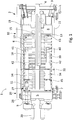
- Fig. 1 illustrates a filter press 1 for separating the solid components from the liquid components of a slurry, preferably a mineral slurry or mineral pulp, according to one exemplary embodiment of the present invention.
- the filter press comprises a press frame 2 having end columns 3 and longitudinally extended side beams 4 adapted to be connected to the end columns.
- the filter press further comprises a stationary end 5 arranged at one end of the side beams 4.
- the stationary end 5 serves in particular to absorb the pressing and tensile forces occurring during manipulation of a filter plate assembly 6 and the filtration process.
- the stationary end comprises a stationary press plate 7 which abuts an outermost filter plate of the filter plate assembly 6.
- the filter press comprises a series of filter plates, a plurality of face-to-face oriented filter plates movable on the side beams 4 in a longitudinal direction of said filter press 1.
- the series of filter plates is herein also referred to as a filter plate assembly 6 or filter pack.
- the filter plate assembly 6 is arranged, located, between the stationary end 5 and a movable head 8. In this figure the filter plates are arranged at a distance from each other. Supply lines 9 required for filtration in order to feed in the suspension to be filtered and carry away the filtrate are laid through the stationary end 5.
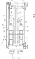
- Fig. 2 illustrates a perspective view of the filter press according to the embodiment shown in Fig. 1 , where the filter plates have been brought together by the movable head 8 and is ready for being pulled together by the press system 26.
- Each filter plate has a recess (not shown) on each one of its two side surfaces which creates a chamber (not shown) together with a corresponding recess of the side surface of a neighbouring filter plate, when the filter plates have been brought together by the movable head 8 and the filter press is being locked by the locking system 10 ( Fig. 2 ).
- Each filter plate further comprises an inlet for receiving the slurry from which the solid components are to be separated from the liquid components, and a plurality of outlets through which the liquid components can exit.
- the outermost filter plate arranged next to the movable head 8 is connected to the movable head, and all other filter plates are connected to this outermost filter plate, for example by chains.
- a movement of the movable head 8 in a direction away from the stationary end causes the filter plates to be pulled apart from one another ( FIG. 1 ), and the filter cake typically drops down onto a chute (not shown in the figure) arranged for receiving the filter cake.
- the filter press 1 further comprises a movable head 8 which is adapted to transport the filter plate assembly arranged on the side beams in a longitudinal direction of the filter press.
- the movable head comprises a carriage 11 wherein said carriage is adapted to move along the side beams by means of a drive unit 20 and a linear transmission 50.
- the carriage 11 is provided with supporting guide rollers 12 which are adapted to roll on the side beams.
- the guide rollers 12 are arranged in pairs to roll on the upper and lower horizontal contact surfaces of the side beams, respectively.
- the movable head 8 further comprises a press plate 13 which is directed towards the filter plate assembly and a rear side 14 directed away from the filter plate assembly.
- the press plate 13 is preferably substantially rectangular or square.
- the outline of the press plate is provided with recesses 15 on the vertical sides to provide space for the side beams 4 and a linear transmission 50.
- the movable head 8 can travel at high and adjustable speeds and efficiently transport a large number of filter plates along the side beams 4.
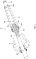
- Fig. 3 illustrates a perspective view of the rear end of the movable head 8 of the filter press according to the embodiment shown in Fig. 1 and 2 .
- the rear side 14 of the movable head is further provided with at least one support section 16 provided with at least one locking device 19 and at least one through hole 17 for receiving a locking element 18 connected to the press system 26.
- the movable head comprises two support sections 16 which are provided with four through holes 17 and four locking devices 19.
- the movable head 8 is adapted to be movable along the longitudinal axis of the side beams 4 with the aid of at least one drive unit 20 and linear transmission 50.
- the carriage 11 comprises a shaft and bearing house 21 wherein the drive unit 20 comprising an electric motor 22 and gearbox 23 is mounted.
- the linear transmission 50 comprises at least one gear wheel 24 adapted to mesh with at least one toothed rack 25.
- the at least one gear wheel 24 is mounted on the carriage 11 and the at least one toothed rack 25 is mounted on the side beams 4.
- the drive unit 20 is arranged on the carriage 11 such that the drive unit moves with the carriage.
- the at least one toothed rack 25 may be mounted on a side beam 4 of the frame and the at least one gear wheel 24 is connected to the gearbox 23 and an electrical motor 22.
- the gear wheel is meshed with the toothed rack to move the carriage 11 along the side beams.
- the drive unit 20 is adapted to drive at least one gear wheel 24 that meshes with at least one toothed rack 25 mounted on the side beams.
- the toothed rack 25 has teeth facing downwards.
- the drive unit 20 drives the movable head 8 by the toothed rack along the side beams towards the filter plate assembly 6 and consequently moves the filter plate assembly 6 from an open position (illustrated in FIG. 1 ) to an operation position where the filter plates are close to each other and the filtration process may be performed (illustrated in FIG. 2 ).
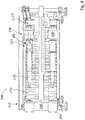
- Fig. 4 illustrates another embodiment of the filter press wherein the carriage 11 carries the press plate and locking devices 19 but not the drive unit 20.
- the drive unit 20 is stationary arranged and the press plate 13 is moved by the carriage 11.
- the at least one gear wheel 24 is fixed mounted on the side beam and the at least one toothed rack is attached to the carriage 11.
- the at least one toothed rack is arranged to be displaced with the carriage 11 and the gear wheel fixed mounted to be connected to the drive unit 20.
- One end of the at least one toothed rack 25 is mounted to the carriage 11 and the other end of the at least one toothed rack is arranged to interact with the gear wheel 24 connected to the drive unit.
- the stationary gear wheel meshes 24 with the movable toothed rack to move the carriage along the side beams.
- the carriage only carries the press plate, thus the carriage may be moved in a high and variable speed along the side beams.
- the movable head can travel at high speeds and transport a large number of filter plates along the side beams.
- Fig. 1-3 further illustrates that the filter press comprises press system 26 and locking system 10.
- the locking system 10 is adapted to lock the movable head in an operation position prior to the filtration process.
- the filter press is locked when the locking system 10 is activated and in operation.
- the press system 26 may be activated to exert a pulling force, a closing pressure, on the filter plates thereby pressing them against each other and sealing them tightly together to ensure that the filtration process can be performed without leakage.
- the press system 26 comprises at least one actuator adapted for converting rotational motion to linear motion.
- FIG. 1 schematically illustrates an actuator 27 according to one or more embodiments of the present invention.
- the actuator 27 converts rotary drive supplied by electrical drive means 29 into an axially directed force which is applied to the filter plate assembly 6 during filtration.
- the filter press 1 comprises four actuators 27, one pair of actuators are arranged on each vertical side of said filter plate assembly.
- the press system 26 comprises a bearing house 28 and electrical drive means 29.
- the bearing house 28 is arranged inside the stationary end 5.
- the electrical drive means 29, an electrical motor, is provided on the side of the stationary end 5 which is directed away from the filter press.
- the actuators 27 are connected to the electrical drive means 29.
- each actuator 27 extends from the stationary end 5 in the longitudinal direction of the filter press 1 towards the movable head.
- each actuator 27 of the press system 26 comprise a planetary roller screw assembly 31 (which is illustrated in dashed lines in Fig. 1 ) and an actuator housing 45.
- the actuator 27 is adapted to convert rotary drive by the electrical drive means 29 into an axially directed force that acts on the filter plates 6 by means of the press plate 13 to close and seal the filter plate assembly.
- Fig. 5 illustrates one embodiment of the actuator 27 which is configured as a planetary roller screw assembly 31.
- the planetary roller screw assembly 31 comprises a main threaded shaft 32, a planetary roller nut 33a and an extension element 34.
- the main threaded shaft 32 also called the planetary roller screw shaft 32, is connected to the electrical drive means 29 via the bearing house 28.
- the main threaded shaft 32 is subjected to large axial forces, therefore preferably a multi- jack bolt tensioner 35 is used for attaching the main threaded planetary shaft 32 to the bearing house 28.
- the actuator housing 45 is adapted to cover the main threaded shaft, the planetary nut and at least a part of the extension element 34.
- the planetary roller nut 33a comprises an arrangement of threaded rollers 38a which interacts with the threaded planetary shaft 32 to convert rotational motion into linear motion. Specifically, the threads on the planetary shaft 32 and on the threaded rollers 38a causes the planetary roller nut 33a to be displaced in the axial direction along the axis of the main threaded shaft in response to rotary drive of the threaded main shaft 32 such that an axially directed force, a pressure force, is generated or removed by the press system 26.
- the moving direction of the planetary roller nut 33a is determined by the rotational direction of the main threaded shaft.
- the threaded planetary shaft 32 is driven in a first direction by the electrical motor such that the actuator 27 exerts a pulling force, a closing pressure, on the filter plate assembly to seal the assembly.
- Fig. 6 illustrates another embodiment of the actuator 27 which is configured as a planetary ball screw assembly.
- the planetary ball screw assembly comprises a main threaded shaft 32, a planetary ball nut 33b and an extension element 34.
- the planetary ball screw assembly provides the same function as the planetary roller screw assembly and is therefore not further described herein.
- Fig. 1 , 2 , 5 and 6 further shows an extension member 34 fixedly attached to the planetary nut of the actuator 27 in order to perform the same movement as the planetary nut 33a,33b.
- the extension member comprises a longitudinally extended cylindrically formed shell having a first end 36a and a projecting end 36b.
- Preferably the extension member is concentrically arranged with the planetary screw shaft.
- the inside perimeter 37 of the first end 36a of the extension member is fixedly attached to the outside circumference 36c of the planetary nut.
- the extension member 34 extends from the planetary nut towards the locking system and the movable head 8.
- the extension member 34 is directed towards the movable head 8.
- the projecting end 36b of the extension member is connected to locking element 18.
- Fig. 5 shows that the planetary roller nut 33a is attached to the extension element 34, thus when the planetary roller nut is displaced along the threaded main shaft 32, the extension element 34 is also axially displaced in the same direction. Accordingly, the position of the extension element 34 can be adjusted by rotating the main threaded shaft 32 in the appropriate direction. Because of the number of threaded rollers 38a which surround the main threaded shaft 32 and which are in continuous contact with main threaded shaft, the axially directed actuating force derived from the rotary drive is applied on a greater surface area, thus a large amount of thrust is provided to effectively close and tighten the filter plate assembly. A very high closing pressure may therefore be achieved by the press system 26 according to the present invention.
- the filter plate assembly 6 arranged between the stationary end 5 and the movable head 8 are thus tightly sealed together.
- the cycle time is significantly reduced and substantial energy savings can be achieved in comparison to conventional filter presses since both the movable head and the press system are driven by electrical drive means.
- Another advantage is that no hydraulic cylinders are used for transport of the filter plates or for closing of the filter press, thus the filter press described herein is environmentally sustainable since no hydraulic oil is required to perform the filtration process.
- Fig. 1 and 2 further show a fixing member 30 which is attached to the side beam 4 of the frame 3.
- the fixing member 30 is connected to the planetary nut 33a, 33b or the extension member 34.
- the fixing member 30 is preferably adapted to permit axial displacement of the planetary nut and the extension member along the axial direction the planetary shaft.
- the purpose of the fixing member 30 is to prevent the planetary nut or the extension member from rotating when the press system is activated, such that the electrically driven actuator may generate an axially directed force to pull the filter plates towards the stationary end 5.
- Fig. 1-3 further show a locking system 10 which is adapted to interconnect the movable head 8 and the stationary end 5.
- the locking system provides that the movable head 8 and the stationary end 5 can be releasable locked together.
- the locking system provides that the movable head 8 maybe locked to the press system 26.
- the locking system 10 comprises at least one locking element 18 and at least one locking device 19, wherein said locking device 19 is adapted to engage around said locking element.
- the locking system 10 comprises four locking element 18 and four clamping devices 19.
- Fig. 1 and Fig. 2 illustrate that the locking element 18 is attached to the actuator 27 of the press system.
- the locking element 18 comprises a rod member 39 having a rod end portion 40 and a recess 41 preferably provided around the circumference of the rod member and a stop member 42 arranged on the end projecting end of the clam-connector.
- the locking element 18 projects towards the movable head, and is specifically aligned with a through hole 17 in said movable head, and arranged to cooperate with the locking element.
- the locking element 18 is configured to be inserted into said through hole 17.
- a contact surface 43 on the movable head may abut the stop member 42.
- the locking element 18 has a cross section corresponding to the through hole 17 of the movable head 8 to align the locking element 18 correctly with the locking device 19 arranged on the second side of the movable head. The locking element 18 can thus mesh exactly with the locking device 19.
- each locking device 19 is arranged on the rear side 14 of the movable head and at respective through hole 17.
- the locking device is configured as a pair of clamping jaws adapted to releasable clamp around the rod end portion 40 and to engage with the recess 41 in the rod member thereby forming a locking connection between the locking element 18 and the movable head.
- the locking device 19 is shifted between an open and closed state using a lever 44.
- the lever is extendable in a direction along the length of the locking device and will force the locking device into the closed state when fully extended. When the lever is fully retracted the locking device is in turn placed in the open state.
- the filter press When the locking device is closed, the filter press is in position for operation.
- the filter plate assembly 6 may then be closed by the press system 26 and the filtration process can be performed.
- the filter plate assembly In order to remove the filter cake upon completion of filtration, the filter plate assembly must be pulled apart. For this purpose, the pressure force on the filter plate assembly is reduced by the actuator.
- the locking system 10 is unlocked by opening the locking device 19. The movable head may then pull the filter plates apart and transport the filter plates from the operation position to an open position of the filter plates.
- Fig. 7 illustrates another embodiment of the filter press 100 having filter plates 106, press system 126 and actuator 127 configured as a planetary screw assembly 131.
- the planetary nut is attached to the stationary end 105 inside the housing 128 and the planetary shaft is arranged to move in the axial direction.
- the planetary nut 133 is arranged to be rotated, driven by electrical driving means 129 attached to the stationary end 105.
- the filter press further comprises a locking system 110 of same type as filter press 1.
- the press system 126 operates in similar manner as the previously described press system 26.
- the filter press 100 comprises further features corresponding to features of filter press 1 which are therefore not described here.
- Fig. 8 shows another embodiment of the filter press 200 with filter plates 206 comprising a press system 226 with an actuator 227 configured as a planetary screw assembly 231 extends from a movable head 208 in the longitudinal direction of the filter press towards a stationary end 205.
- the press system comprises electrical drive means 229 attached to the movable head 208.
- the filter press further comprises a locking system 210 comprising locking device 219 and locking element 218.
- the filter press 200 operates in similar manner as the previously described filter press 1. As illustrated, the filter press 200 comprises further features corresponding to features of filter press 1 which are therefore not described here.
- the filter press according to the embodiment illustrated in Fig. 1- 3 operates as follows: The movable head 8 is located first of all in an open position farthest away from the stationary end 5 - the open position. The filter press 1 is completely open and the filter plates 6 are spread out.
- the movable head 8 is driven by electrical drive means 29 to move towards the stationary end 6 and bring the filter plates together and closes the filter press as it does so.
- the filter plates are transported along the side beams and the filter press reaches a closed but not locked position.
- Locking element 18 are received by the locking device 19 arranged on the movable head 8.
- the locking system 10 is then activated whereby the locking device is closed to achieve a locking connection between the locking element 18 and the locking device 19.
- the press system 26 is activated whereby the electrically driven actuator 27, the planetary screw assembly, exerts a pulling force, a closing pressure on the movable head whereby the filter press is closed.
- the filtration process can thereafter be performed.
- the filter plates In order to remove the filter cake upon completion of filtration, the filter plates must be pulled apart. For this purpose, first the planetary screw assembly reduces the pressure by exerting a pushing force on the movable head. Thereafter the locking system 10 is deactivated and the locking device 19 is opened.
- the drive unit of the movable head is activated such that the movable head is moved from the operation position by means of the linear transmission 50.
- the outermost filter plate of the series of filter plates facing the movable plate is connected to the movable plate, and all other filter plates are connected to this outermost filter plate, for example by chains.
- the movement of the movable head 8 causes the filter plates to be pulled apart from one another, and the filter cakes drops to down to collecting chute under the force of gravity.
- the filter press according to the invention thus provides the necessary pressure for performing the filtration process on the one hand, but also allows the filter plates to be opened and closed rapidly on the other hand.
- the filter plates may have a rectangular or square shape.
- the locking device may be placed and arranged differently as long as it interconnects the movable head and the stationary head and locks the movable head to the press system.
- the inlets and outlets of the filter plates may be placed at any suitable location on the filter plates.
- the electrical drive means of the present invention may comprise a hydraulic motor driven by an electrical hydraulic pump. The advantage of reduced amounts of hydraulic oil is maintained with this solution since the volume of the hydraulic can be kept to a minimum with this solution.
Landscapes
- Chemical & Material Sciences (AREA)
- Chemical Kinetics & Catalysis (AREA)
- Engineering & Computer Science (AREA)
- Mechanical Engineering (AREA)
- Filtration Of Liquid (AREA)
- Press Drives And Press Lines (AREA)
Claims (15)
- Filterpresse (1, 100, 200) zum Trennen der Feststoffkomponenten von den flüssigen Komponenten einer Aufschlämmung, umfassend Seitenträger (4) und mehrere Filterplatten (6, 106, 206), die im rechten Winkel zur Längsrichtung der Seitenträger ausgerichtet sind, wobei die Filterplatten (6, 106, 206) dazu ausgeführt sind, sich entlang den Seitenträgern zu bewegen, ein stationäres Ende (5, 105, 205), das an oder nahe einem Ende der Seitenträger angeordnet ist, einen beweglichen Kopf (8, 108, 208), der dazu ausgeführt ist, die Filterplatten entlang den Seitenträgern zu transportieren, ein Presssystem (26, 126, 226), das dazu ausgeführt ist, einen Schließdruck auf die Filterplatten auszuüben, um die Filterplatten gegeneinander zu drücken, dadurch gekennzeichnet, dass das Presssystem (26, 126, 226) mindestens einen elektrisch angetriebenen Aktor (27, 127, 227) umfasst, der dazu ausgeführt ist, eine axial gerichtete Kraft zu erzeugen, die mittels des beweglichen Kopfs (8, 108, 208) auf die Filterplatten ausgeübt wird, wobei der Aktor (27, 127, 227) eine Planetengewindeanordnung (31, 131, 231) umfasst und eine elektrische Antriebseinheit (20) dazu angeordnet ist, den beweglichen Kopf (8, 108, 208) während des Transports der Filterplatten (6, 106, 206) anzutreiben, wobei die elektrische Antriebseinheit (20) von dem elektrisch angetriebenen Aktor (27, 127, 227) getrennt ist.
- Filterpresse nach Anspruch 1, wobei der Aktor (27, 127, 227) dazu ausgeführt ist, Drehantrieb in eine axial gerichtete Kraft umzuwandeln.
- Filterpresse nach Anspruch 1, wobei der Aktor (27, 127, 227) dazu ausgeführt ist, Drehantrieb in eine axial gerichtete Zugkraft umzuwandeln.
- Filterpresse nach Anspruch 1, wobei die Planetengewindeanordnung (31) eine mit einem Gewinde versehene Planetengewindewelle (32) und eine Planetenmutter (33a, 33b) umfasst, die dazu ausgeführt ist, mit der Planetengewindewelle zusammenzuwirken, und die Planetengewindewelle in einer festen Position angeordnet ist und die Planetenmutter dazu angeordnet ist, in der Längsrichtung beweglich zu sein, so dass die Planetenmutter (33a, 33b) als Reaktion auf einen Drehantrieb der mit einem Gewinde versehenen Planetengewindewelle in der axialen Richtung der Planetengewindewelle (32) verschoben wird; oder wobei die Planetengewindeanordnung (31) eine mit einem Gewinde versehene Planetengewindewelle (32) und eine Planetenmutter (33a, 33b) umfasst, die dazu angeordnet ist, mit der Planetengewindewelle zusammenzuwirken, und die Planetenmutter in einer festen Position angeordnet ist und die Planetengewindewelle dazu angeordnet ist, in der Längsrichtung beweglich zu sein, so dass die Planetengewindewelle (32) als Reaktion auf einen Drehantrieb der Planetenmutter (33a, 33b) bezüglich der Planetenmutter (33a, 33b) in der axialen Richtung der Planetengewindewelle (32) verschoben wird.
- Filterpresse nach einem der vorhergehenden Ansprüche, wobei das Presssystem (26, 126) an dem stationären Ende (5, 105) angebracht ist oder wobei das Presssystem (226) an dem beweglichen Kopf (208) angebracht ist.
- Filterpresse nach einem der vorhergehenden Ansprüche, wobei der bewegliche Kopf (8, 108, 208) einen Schlitten (11) und eine zu der Filterplattenanordnung (6) gerichtete Pressplatte (13) umfasst, wobei der Schlitten dazu ausgeführt ist, sich mittels einer Antriebseinheit (20) und eines Lineargetriebes (50) entlang den Seitenträgern zu bewegen.
- Filterpresse nach Anspruch 6, ferner umfassend, dass die Antriebseinheit (20) an dem Schlitten (11) angeordnet ist und dass das Lineargetriebe (50) mindestens ein Zahnrad (24), das an dem Schlitten angebracht ist, und mindestens eine Zahnstange (25), die an dem Seitenträger (4) angebracht ist, umfasst, wobei die Antriebseinheit dazu ausgeführt ist, mittels des Lineargetriebes den beweglichen Kopf entlang den Seitenträgern anzutreiben.
- Filterpresse nach Anspruch 6, ferner umfassend, dass die Antriebseinheit (20) stationär an dem Pressenrahmen (3) angeordnet ist und dass das Lineargetriebe (50) mindestens ein Zahnrad (24), das an dem Rahmen angebracht ist, und mindestens eine Zahnstange (25), die an dem Schlitten (11) angebracht ist, umfasst, wobei die Antriebseinheit dazu ausgeführt ist, mittels des Lineargetriebes den beweglichen Kopf entlang den Seitenträgern anzutreiben.
- Filterpresse nach einem der vorhergehenden Ansprüche, ferner umfassend ein Verriegelungssystem (10, 110, 210), das dazu ausgeführt ist, den beweglichen Kopf (8, 108, 208) und das stationäre Ende (5, 105, 205) miteinander zu verbinden.
- Filterpresse nach einem der vorhergehenden Ansprüche, ferner umfassend ein Verriegelungssystem (10, 110, 210), das dazu ausgeführt ist, den beweglichen Kopf (8) in Eingriff mit dem Presssystem zu verriegeln.
- Filterpresse nach einem der vorhergehenden Ansprüche, wobei der Aktor (27, 127) mit dem beweglichen Kopf (8, 108) verbunden ist, um die durch den Aktor erzeugte axial gerichtete Kraft auf den beweglichen Kopf und die Filterplatten zu übertragen.
- Verfahren zum Trennen der Feststoffkomponenten von den flüssigen Komponenten einer Aufschlämmung, das eine Filterpresse (1, 100, 200) verwendet, die mehrere Filterplatten (6, 106, 206) umfasst, wobei das Verfahren die Schritte des Platzierens der Filterpresse in einer Betriebsposition durch Transportieren der Filterplatten zu einem stationären Ende (5, 105, 205) durch einen beweglichen Kopf (8, 108, 208), Ausüben einer Schließkraft auf die Filterplatten durch ein Presssystem (26, 126, 226), das dazu ausgeführt ist, die Filterplatten (6, 106, 206) durch elektrisches Antreiben mindestens eines Aktors (27, 127, 227), der mindestens eine Planetengewindeanordnung (31) umfasst und dazu ausgeführt ist, eine axial gerichtete Kraft zu erzeugen, die mittels des beweglichen Kopfs auf die Filterplatten ausgeübt wird, gegeneinander zu drücken, Einspritzen der Aufschlämmung zwischen die Filterplatten und Trennen der Feststoffkomponenten von den flüssigen Komponenten der sich zwischen den Filterplatten befindenden Aufschlämmung, wobei der Schritt des Ausübens eines Schließdrucks auf die Filterplatten durch das Presssystem (26, 126, 226) Antreiben der mindestens einen Planetengewindeanordnung (31) durch ein elektrisches Antriebsmittel (29, 129, 229), Antreiben des beweglichen Kopfs (8, 108), 208) während des Transports der Filterplatten (6, 106, 206) mit einer elektrischen Antriebseinheit (20) umfasst, wobei die elektrische Antriebseinheit (20) von dem elektrisch angetriebenen Aktor (27, 127, 227) getrennt ist.
- Verfahren nach Anspruch 12, wobei der Schritt des Ausübens eines Schließdrucks auf die Filterplatten Verschieben einer Planetenmutter (33a, 33b) in der axialen Richtung der mit einem Gewinde versehenen Planetengewindewelle (32a, 32b) als Reaktion auf einen Drehantrieb der Planetengewindewelle oder Verschieben der Planetengewindewelle (32a, 32b) in der axialen Richtung bezüglich der Planetenmutter (33a, 33b) als Reaktion auf einen Drehantrieb der Planetenmutter (33a, 33b) umfasst.
- Verfahren nach einem der Ansprüche 12-13, wobei der Schritt des Ausübens eines Schließdrucks auf die Filterplatten elektrisches Antreiben von mindestens zwei Aktoren (27, 127, 227) und Ausüben von axial gerichteten Kräften von gleicher Größe auf die Filterplatten durch die Aktoren oder Ausüben von axial gerichteten Kräften verschiedener Größe auf die Filterplatten durch die Aktoren umfasst.
- Verfahren nach einem der Ansprüche 13-15, ferner umfassend den Schritt des Verriegelns des beweglichen Kopfs (8, 108, 208) in einer Betriebsposition durch ein Verriegelungssystem (10, 110, 210).
Applications Claiming Priority (2)
| Application Number | Priority Date | Filing Date | Title |
|---|---|---|---|
| EP17197183.1A EP3473319A1 (de) | 2017-10-18 | 2017-10-18 | Filterplattenanordnung und verfahren zum trennen der feststoffkomponenten von den flüssigen komponenten einer aufschlämmung |
| PCT/EP2018/078590 WO2019077055A1 (en) | 2017-10-18 | 2018-10-18 | PRESS FILTER AND METHOD FOR SEPARATING THE SOLID COMPONENTS FROM THE LIQUID COMPONENTS OF A SUSPENSION |
Publications (2)
| Publication Number | Publication Date |
|---|---|
| EP3697516A1 EP3697516A1 (de) | 2020-08-26 |
| EP3697516B1 true EP3697516B1 (de) | 2021-12-29 |
Family
ID=60191113
Family Applications (2)
| Application Number | Title | Priority Date | Filing Date |
|---|---|---|---|
| EP17197183.1A Withdrawn EP3473319A1 (de) | 2017-10-18 | 2017-10-18 | Filterplattenanordnung und verfahren zum trennen der feststoffkomponenten von den flüssigen komponenten einer aufschlämmung |
| EP18785977.2A Active EP3697516B1 (de) | 2017-10-18 | 2018-10-18 | Filterplattenanordnung und verfahren zum trennen der feststoffkomponenten von den flüssigen komponenten einer aufschlämmung |
Family Applications Before (1)
| Application Number | Title | Priority Date | Filing Date |
|---|---|---|---|
| EP17197183.1A Withdrawn EP3473319A1 (de) | 2017-10-18 | 2017-10-18 | Filterplattenanordnung und verfahren zum trennen der feststoffkomponenten von den flüssigen komponenten einer aufschlämmung |
Country Status (14)
| Country | Link |
|---|---|
| US (1) | US11833453B2 (de) |
| EP (2) | EP3473319A1 (de) |
| CN (1) | CN111315463A (de) |
| AU (1) | AU2018351614B2 (de) |
| CL (1) | CL2020001037A1 (de) |
| DK (1) | DK3697516T3 (de) |
| ES (1) | ES2911251T3 (de) |
| MX (1) | MX2020004057A (de) |
| PE (1) | PE20200911A1 (de) |
| PT (1) | PT3697516T (de) |
| RU (1) | RU2767378C2 (de) |
| UA (1) | UA126768C2 (de) |
| WO (1) | WO2019077055A1 (de) |
| ZA (1) | ZA202002585B (de) |
Families Citing this family (11)
| Publication number | Priority date | Publication date | Assignee | Title |
|---|---|---|---|---|
| DE102019112615B4 (de) * | 2019-05-14 | 2022-09-29 | Sartorius Stedim Biotech Gmbh | Filtrations-Vorrichtungsanordnung mit Filterpresse |
| RS65373B1 (sr) * | 2019-12-20 | 2024-04-30 | Metso Finland Oy | Komplet za pritiskanje i transport filterskih ploča za naknadnu ugradnju za filter presu |
| EP3838368B1 (de) * | 2019-12-20 | 2024-01-03 | Metso Finland Oy | Filterpresse und verfahren zur steuerung davon |
| PE20221607A1 (es) * | 2019-12-20 | 2022-10-10 | Metso Outotec Finland Oy | Un filtro prensa y una placa de compresion de filtrado y kit de transporte de reequipamiento para un filtro prensa |
| EP4135870B1 (de) * | 2020-04-17 | 2025-04-16 | Metso Finland Oy | Filterplattenrahmenanordnung und horizontale filterpresse, wie eine turmpresse, mit einer solchen plattenrahmenanordnung |
| JP7839114B2 (ja) * | 2020-06-09 | 2026-04-01 | 武田薬品工業株式会社 | フィルタプレスアダプタ |
| CN111701292A (zh) * | 2020-07-03 | 2020-09-25 | 山东润德生物科技有限公司 | 板框过滤系统 |
| CN112159010B (zh) * | 2020-09-24 | 2023-09-12 | 湖南诚至环保科技有限公司 | 一种水源污染处理方法及系统 |
| CN112121482B (zh) * | 2020-10-12 | 2023-03-14 | 株洲时代新材料科技股份有限公司 | 一种悬梁式压滤机 |
| CN114681967A (zh) | 2020-12-31 | 2022-07-01 | 美卓奥图泰芬兰有限公司 | 压滤机 |
| CN113750590B (zh) * | 2021-09-29 | 2022-09-20 | 广西埃索凯新材料科技有限公司 | 一种硫酸锰生产过程中的压滤系统 |
Family Cites Families (16)
| Publication number | Priority date | Publication date | Assignee | Title |
|---|---|---|---|---|
| DE1411745B2 (de) | 1962-03-17 | 1971-07-15 | Seitz Werke GmbH, 6550 Bad Kreuznach | Handradanordnung insbesondere fuer anpressvorrichtung an filterpressen |
| US3404580A (en) * | 1967-04-18 | 1968-10-08 | Sargent Industries | Ball screw actuator |
| DE2415598C2 (de) * | 1974-03-30 | 1983-09-08 | Eberhard Hoesch & Söhne GmbH & Co, 5160 Düren | Plattenpreßfilter |
| SU960246A1 (ru) * | 1979-12-03 | 1982-09-23 | Киевский Технологический Институт Пищевой Промышленности | Фильтр-пресс дл разделени пивных заторов |
| DE3636799A1 (de) * | 1986-10-29 | 1988-05-05 | Rittershaus & Blecher Gmbh | Verfahren zur regelung des filterplatten-anlagedruckes bei filterpressen und vorrichtung zur durchfuehrung des verfahrens |
| SU1662616A1 (ru) | 1988-05-31 | 1991-07-15 | Бердичевское Производственное Объединение Химического Машиностроения "Прогресс" | Фильтр-пресс |
| JPH0463107A (ja) * | 1990-03-16 | 1992-02-28 | Toufuku Kk | フイルタプレスの圧締装置 |
| JP3539310B2 (ja) * | 1999-10-05 | 2004-07-07 | 株式会社石垣 | フイルタープレスの締付装置並びにその締付方法 |
| FR2844019A1 (fr) * | 2002-08-29 | 2004-03-05 | Innovation Technologie Conseil | Actionneur mecanique a friction comprenant un ecrou interne a billes dans lequel les billes sont montees avec precontrai nte |
| RU39503U1 (ru) | 2004-05-24 | 2004-08-10 | Закрытое акционерное общество "Кыштымский медеэлектролитный завод" | Рамный фильтр-пресс |
| AT505541B1 (de) | 2007-12-20 | 2009-02-15 | Andritz Tech & Asset Man Gmbh | Filterpresse |
| ITMS20090002A1 (it) | 2009-02-10 | 2010-08-11 | Stefano Tongiani | Filtropressa ad azione combinata |
| CN102179084B (zh) * | 2011-03-24 | 2016-03-09 | 宋家骏 | 开闭自锁压紧机构 |
| JP5624018B2 (ja) * | 2011-12-21 | 2014-11-12 | 月島機械株式会社 | フィルタプレス装置 |
| CN104190125A (zh) * | 2014-07-07 | 2014-12-10 | 景津环保股份有限公司 | 高压压榨液压压紧机械螺旋锁紧压滤机 |
| CN206444260U (zh) | 2017-01-21 | 2017-08-29 | 浙江建华集团过滤机有限公司 | 压滤机 |
-
2017
- 2017-10-18 EP EP17197183.1A patent/EP3473319A1/de not_active Withdrawn
-
2018
- 2018-10-18 MX MX2020004057A patent/MX2020004057A/es unknown
- 2018-10-18 RU RU2020115248A patent/RU2767378C2/ru active
- 2018-10-18 EP EP18785977.2A patent/EP3697516B1/de active Active
- 2018-10-18 CN CN201880068201.1A patent/CN111315463A/zh active Pending
- 2018-10-18 UA UAA202002554A patent/UA126768C2/uk unknown
- 2018-10-18 ES ES18785977T patent/ES2911251T3/es active Active
- 2018-10-18 DK DK18785977.2T patent/DK3697516T3/da active
- 2018-10-18 WO PCT/EP2018/078590 patent/WO2019077055A1/en not_active Ceased
- 2018-10-18 PT PT187859772T patent/PT3697516T/pt unknown
- 2018-10-18 AU AU2018351614A patent/AU2018351614B2/en active Active
- 2018-10-18 US US16/756,265 patent/US11833453B2/en active Active
- 2018-10-18 PE PE2020000429A patent/PE20200911A1/es unknown
-
2020
- 2020-04-17 CL CL2020001037A patent/CL2020001037A1/es unknown
- 2020-05-08 ZA ZA2020/02585A patent/ZA202002585B/en unknown
Also Published As
| Publication number | Publication date |
|---|---|
| ZA202002585B (en) | 2022-12-21 |
| RU2020115248A3 (de) | 2022-01-12 |
| RU2020115248A (ru) | 2021-11-18 |
| MX2020004057A (es) | 2020-10-12 |
| ES2911251T3 (es) | 2022-05-18 |
| RU2767378C2 (ru) | 2022-03-17 |
| CL2020001037A1 (es) | 2020-10-23 |
| UA126768C2 (uk) | 2023-02-01 |
| EP3697516A1 (de) | 2020-08-26 |
| DK3697516T3 (da) | 2022-04-04 |
| AU2018351614B2 (en) | 2024-05-09 |
| PT3697516T (pt) | 2022-04-19 |
| AU2018351614A1 (en) | 2020-05-07 |
| WO2019077055A1 (en) | 2019-04-25 |
| US11833453B2 (en) | 2023-12-05 |
| CN111315463A (zh) | 2020-06-19 |
| EP3473319A1 (de) | 2019-04-24 |
| CA3079643A1 (en) | 2019-04-25 |
| BR112020007721A2 (pt) | 2020-10-06 |
| US20200316499A1 (en) | 2020-10-08 |
| PE20200911A1 (es) | 2020-09-14 |
Similar Documents
| Publication | Publication Date | Title |
|---|---|---|
| EP3697516B1 (de) | Filterplattenanordnung und verfahren zum trennen der feststoffkomponenten von den flüssigen komponenten einer aufschlämmung | |
| AU2020406622B2 (en) | A filter press and a filter plate compression and transport retrofitting kit for a filter press | |
| JP2011235436A (ja) | クランプ装置 | |
| RU2480266C2 (ru) | Фильтр-пресс | |
| EP0805020A2 (de) | Vorrichtung zur Drehmoment-Übertragung | |
| EP3838368B1 (de) | Filterpresse und verfahren zur steuerung davon | |
| CA3079643C (en) | Filter press and method for separating the solid components from the liquid components of a slurry | |
| US6972105B2 (en) | Rotary tablet press | |
| EP3470146B1 (de) | Direkt mechanisch-angetriebene strangpresse | |
| EP3838367B1 (de) | Filterplattenkompressions- und transportnachrüstungssatz für eine filterpresse | |
| BR112020007721B1 (pt) | Filtro prensa e método para separar os componentes sólidos dos componentes líquidos de uma pasta usando um filtro prensa | |
| EA047674B1 (ru) | Система для модернизации фильтр-пресса | |
| CN111022600B (zh) | 一种电气联用折返式电动缸 | |
| CN216125245U (zh) | 一种压滤机压紧松开系统 | |
| DE102023126321B4 (de) | Strangpresse | |
| WO1989006580A1 (fr) | Dispositif generateur d'une force de serrage pour actionner un agencement de serrage mecanique de broches principales rotatives | |
| CN120772459A (zh) | 一种锻压件锻压用自动上料装置及其工艺 | |
| WO2022033819A1 (de) | Radialpresse | |
| WO2011160622A1 (de) | Hochaufgeladener expansions-motor | |
| SE1451263A1 (en) | Filter plate assembly and method for separating the solid components from the liquid components of a slurry |
Legal Events
| Date | Code | Title | Description |
|---|---|---|---|
| STAA | Information on the status of an ep patent application or granted ep patent |
Free format text: STATUS: UNKNOWN |
|
| STAA | Information on the status of an ep patent application or granted ep patent |
Free format text: STATUS: THE INTERNATIONAL PUBLICATION HAS BEEN MADE |
|
| PUAI | Public reference made under article 153(3) epc to a published international application that has entered the european phase |
Free format text: ORIGINAL CODE: 0009012 |
|
| STAA | Information on the status of an ep patent application or granted ep patent |
Free format text: STATUS: REQUEST FOR EXAMINATION WAS MADE |
|
| 17P | Request for examination filed |
Effective date: 20200514 |
|
| AK | Designated contracting states |
Kind code of ref document: A1 Designated state(s): AL AT BE BG CH CY CZ DE DK EE ES FI FR GB GR HR HU IE IS IT LI LT LU LV MC MK MT NL NO PL PT RO RS SE SI SK SM TR |
|
| AX | Request for extension of the european patent |
Extension state: BA ME |
|
| DAV | Request for validation of the european patent (deleted) | ||
| DAX | Request for extension of the european patent (deleted) | ||
| GRAP | Despatch of communication of intention to grant a patent |
Free format text: ORIGINAL CODE: EPIDOSNIGR1 |
|
| STAA | Information on the status of an ep patent application or granted ep patent |
Free format text: STATUS: GRANT OF PATENT IS INTENDED |
|
| INTG | Intention to grant announced |
Effective date: 20210624 |
|
| GRAS | Grant fee paid |
Free format text: ORIGINAL CODE: EPIDOSNIGR3 |
|
| GRAA | (expected) grant |
Free format text: ORIGINAL CODE: 0009210 |
|
| STAA | Information on the status of an ep patent application or granted ep patent |
Free format text: STATUS: THE PATENT HAS BEEN GRANTED |
|
| RAP1 | Party data changed (applicant data changed or rights of an application transferred) |
Owner name: METSO OUTOTEC FINLAND OY |
|
| AK | Designated contracting states |
Kind code of ref document: B1 Designated state(s): AL AT BE BG CH CY CZ DE DK EE ES FI FR GB GR HR HU IE IS IT LI LT LU LV MC MK MT NL NO PL PT RO RS SE SI SK SM TR |
|
| REG | Reference to a national code |
Ref country code: GB Ref legal event code: FG4D |
|
| REG | Reference to a national code |
Ref country code: CH Ref legal event code: EP |
|
| REG | Reference to a national code |
Ref country code: DE Ref legal event code: R096 Ref document number: 602018028876 Country of ref document: DE |
|
| REG | Reference to a national code |
Ref country code: AT Ref legal event code: REF Ref document number: 1458254 Country of ref document: AT Kind code of ref document: T Effective date: 20220115 |
|
| REG | Reference to a national code |
Ref country code: IE Ref legal event code: FG4D |
|
| REG | Reference to a national code |
Ref country code: FI Ref legal event code: FGE |
|
| REG | Reference to a national code |
Ref country code: DK Ref legal event code: T3 Effective date: 20220330 |
|
| REG | Reference to a national code |
Ref country code: LT Ref legal event code: MG9D |
|
| REG | Reference to a national code |
Ref country code: SE Ref legal event code: TRGR |
|
| REG | Reference to a national code |
Ref country code: NL Ref legal event code: FP |
|
| REG | Reference to a national code |
Ref country code: PT Ref legal event code: SC4A Ref document number: 3697516 Country of ref document: PT Date of ref document: 20220419 Kind code of ref document: T Free format text: AVAILABILITY OF NATIONAL TRANSLATION Effective date: 20220411 |
|
| PG25 | Lapsed in a contracting state [announced via postgrant information from national office to epo] |
Ref country code: RS Free format text: LAPSE BECAUSE OF FAILURE TO SUBMIT A TRANSLATION OF THE DESCRIPTION OR TO PAY THE FEE WITHIN THE PRESCRIBED TIME-LIMIT Effective date: 20211229 Ref country code: LT Free format text: LAPSE BECAUSE OF FAILURE TO SUBMIT A TRANSLATION OF THE DESCRIPTION OR TO PAY THE FEE WITHIN THE PRESCRIBED TIME-LIMIT Effective date: 20211229 |
|
| REG | Reference to a national code |
Ref country code: GR Ref legal event code: EP Ref document number: 20220400673 Country of ref document: GR Effective date: 20220418 |
|
| REG | Reference to a national code |
Ref country code: ES Ref legal event code: FG2A Ref document number: 2911251 Country of ref document: ES Kind code of ref document: T3 Effective date: 20220518 |
|
| PG25 | Lapsed in a contracting state [announced via postgrant information from national office to epo] |
Ref country code: LV Free format text: LAPSE BECAUSE OF FAILURE TO SUBMIT A TRANSLATION OF THE DESCRIPTION OR TO PAY THE FEE WITHIN THE PRESCRIBED TIME-LIMIT Effective date: 20211229 Ref country code: HR Free format text: LAPSE BECAUSE OF FAILURE TO SUBMIT A TRANSLATION OF THE DESCRIPTION OR TO PAY THE FEE WITHIN THE PRESCRIBED TIME-LIMIT Effective date: 20211229 |
|
| REG | Reference to a national code |
Ref country code: NO Ref legal event code: T2 Effective date: 20211229 |
|
| PG25 | Lapsed in a contracting state [announced via postgrant information from national office to epo] |
Ref country code: SM Free format text: LAPSE BECAUSE OF FAILURE TO SUBMIT A TRANSLATION OF THE DESCRIPTION OR TO PAY THE FEE WITHIN THE PRESCRIBED TIME-LIMIT Effective date: 20211229 Ref country code: SK Free format text: LAPSE BECAUSE OF FAILURE TO SUBMIT A TRANSLATION OF THE DESCRIPTION OR TO PAY THE FEE WITHIN THE PRESCRIBED TIME-LIMIT Effective date: 20211229 Ref country code: RO Free format text: LAPSE BECAUSE OF FAILURE TO SUBMIT A TRANSLATION OF THE DESCRIPTION OR TO PAY THE FEE WITHIN THE PRESCRIBED TIME-LIMIT Effective date: 20211229 Ref country code: EE Free format text: LAPSE BECAUSE OF FAILURE TO SUBMIT A TRANSLATION OF THE DESCRIPTION OR TO PAY THE FEE WITHIN THE PRESCRIBED TIME-LIMIT Effective date: 20211229 |
|
| PG25 | Lapsed in a contracting state [announced via postgrant information from national office to epo] |
Ref country code: PL Free format text: LAPSE BECAUSE OF FAILURE TO SUBMIT A TRANSLATION OF THE DESCRIPTION OR TO PAY THE FEE WITHIN THE PRESCRIBED TIME-LIMIT Effective date: 20211229 |
|
| PG25 | Lapsed in a contracting state [announced via postgrant information from national office to epo] |
Ref country code: IS Free format text: LAPSE BECAUSE OF FAILURE TO SUBMIT A TRANSLATION OF THE DESCRIPTION OR TO PAY THE FEE WITHIN THE PRESCRIBED TIME-LIMIT Effective date: 20220429 |
|
| REG | Reference to a national code |
Ref country code: DE Ref legal event code: R097 Ref document number: 602018028876 Country of ref document: DE |
|
| PG25 | Lapsed in a contracting state [announced via postgrant information from national office to epo] |
Ref country code: AL Free format text: LAPSE BECAUSE OF FAILURE TO SUBMIT A TRANSLATION OF THE DESCRIPTION OR TO PAY THE FEE WITHIN THE PRESCRIBED TIME-LIMIT Effective date: 20211229 |
|
| PLBE | No opposition filed within time limit |
Free format text: ORIGINAL CODE: 0009261 |
|
| STAA | Information on the status of an ep patent application or granted ep patent |
Free format text: STATUS: NO OPPOSITION FILED WITHIN TIME LIMIT |
|
| 26N | No opposition filed |
Effective date: 20220930 |
|
| PG25 | Lapsed in a contracting state [announced via postgrant information from national office to epo] |
Ref country code: SI Free format text: LAPSE BECAUSE OF FAILURE TO SUBMIT A TRANSLATION OF THE DESCRIPTION OR TO PAY THE FEE WITHIN THE PRESCRIBED TIME-LIMIT Effective date: 20211229 |
|
| REG | Reference to a national code |
Ref country code: AT Ref legal event code: UEP Ref document number: 1458254 Country of ref document: AT Kind code of ref document: T Effective date: 20211229 |
|
| PG25 | Lapsed in a contracting state [announced via postgrant information from national office to epo] |
Ref country code: MC Free format text: LAPSE BECAUSE OF FAILURE TO SUBMIT A TRANSLATION OF THE DESCRIPTION OR TO PAY THE FEE WITHIN THE PRESCRIBED TIME-LIMIT Effective date: 20211229 |
|
| REG | Reference to a national code |
Ref country code: CH Ref legal event code: PL |
|
| PG25 | Lapsed in a contracting state [announced via postgrant information from national office to epo] |
Ref country code: LU Free format text: LAPSE BECAUSE OF NON-PAYMENT OF DUE FEES Effective date: 20221018 |
|
| PG25 | Lapsed in a contracting state [announced via postgrant information from national office to epo] |
Ref country code: LI Free format text: LAPSE BECAUSE OF NON-PAYMENT OF DUE FEES Effective date: 20221031 Ref country code: CH Free format text: LAPSE BECAUSE OF NON-PAYMENT OF DUE FEES Effective date: 20221031 |
|
| P01 | Opt-out of the competence of the unified patent court (upc) registered |
Effective date: 20230627 |
|
| PG25 | Lapsed in a contracting state [announced via postgrant information from national office to epo] |
Ref country code: IE Free format text: LAPSE BECAUSE OF NON-PAYMENT OF DUE FEES Effective date: 20221018 |
|
| PG25 | Lapsed in a contracting state [announced via postgrant information from national office to epo] |
Ref country code: CY Free format text: LAPSE BECAUSE OF FAILURE TO SUBMIT A TRANSLATION OF THE DESCRIPTION OR TO PAY THE FEE WITHIN THE PRESCRIBED TIME-LIMIT Effective date: 20211229 |
|
| PG25 | Lapsed in a contracting state [announced via postgrant information from national office to epo] |
Ref country code: MK Free format text: LAPSE BECAUSE OF FAILURE TO SUBMIT A TRANSLATION OF THE DESCRIPTION OR TO PAY THE FEE WITHIN THE PRESCRIBED TIME-LIMIT Effective date: 20211229 Ref country code: HU Free format text: LAPSE BECAUSE OF FAILURE TO SUBMIT A TRANSLATION OF THE DESCRIPTION OR TO PAY THE FEE WITHIN THE PRESCRIBED TIME-LIMIT; INVALID AB INITIO Effective date: 20181018 |
|
| PG25 | Lapsed in a contracting state [announced via postgrant information from national office to epo] |
Ref country code: MT Free format text: LAPSE BECAUSE OF FAILURE TO SUBMIT A TRANSLATION OF THE DESCRIPTION OR TO PAY THE FEE WITHIN THE PRESCRIBED TIME-LIMIT Effective date: 20211229 |
|
| PGFP | Annual fee paid to national office [announced via postgrant information from national office to epo] |
Ref country code: GR Payment date: 20250911 Year of fee payment: 8 |
|
| PGFP | Annual fee paid to national office [announced via postgrant information from national office to epo] |
Ref country code: NL Payment date: 20250912 Year of fee payment: 8 Ref country code: IT Payment date: 20250922 Year of fee payment: 8 |
|
| PGFP | Annual fee paid to national office [announced via postgrant information from national office to epo] |
Ref country code: BE Payment date: 20250917 Year of fee payment: 8 Ref country code: BG Payment date: 20250916 Year of fee payment: 8 Ref country code: GB Payment date: 20250904 Year of fee payment: 8 |
|
| PGFP | Annual fee paid to national office [announced via postgrant information from national office to epo] |
Ref country code: FR Payment date: 20250922 Year of fee payment: 8 |
|
| PGFP | Annual fee paid to national office [announced via postgrant information from national office to epo] |
Ref country code: SE Payment date: 20250910 Year of fee payment: 8 |
|
| PGFP | Annual fee paid to national office [announced via postgrant information from national office to epo] |
Ref country code: PT Payment date: 20251013 Year of fee payment: 8 |
|
| PGFP | Annual fee paid to national office [announced via postgrant information from national office to epo] |
Ref country code: DE Payment date: 20250902 Year of fee payment: 8 |
|
| PGFP | Annual fee paid to national office [announced via postgrant information from national office to epo] |
Ref country code: NO Payment date: 20251009 Year of fee payment: 8 |
|
| PGFP | Annual fee paid to national office [announced via postgrant information from national office to epo] |
Ref country code: AT Payment date: 20250925 Year of fee payment: 8 |
|
| PGFP | Annual fee paid to national office [announced via postgrant information from national office to epo] |
Ref country code: FI Payment date: 20251014 Year of fee payment: 8 Ref country code: DK Payment date: 20251014 Year of fee payment: 8 |
|
| PGFP | Annual fee paid to national office [announced via postgrant information from national office to epo] |
Ref country code: TR Payment date: 20251009 Year of fee payment: 8 |
|
| PGFP | Annual fee paid to national office [announced via postgrant information from national office to epo] |
Ref country code: CZ Payment date: 20251006 Year of fee payment: 8 |
|
| PGFP | Annual fee paid to national office [announced via postgrant information from national office to epo] |
Ref country code: ES Payment date: 20251105 Year of fee payment: 8 |
|
| REG | Reference to a national code |
Ref country code: NL Ref legal event code: HC Owner name: METSO FINLAND OY; FI Free format text: DETAILS ASSIGNMENT: CHANGE OF OWNER(S), CHANGE OF OWNER(S) NAME; FORMER OWNER NAME: METSO OUTOTEC FINLAND OY Effective date: 20260311 |
|
| REG | Reference to a national code |
Ref country code: ES Ref legal event code: PC2A Owner name: METSO FINLAND OY Effective date: 20260331 |