EP3699112A1 - Entrepôt, en particulier entrepôt navette - Google Patents
Entrepôt, en particulier entrepôt navette Download PDFInfo
- Publication number
- EP3699112A1 EP3699112A1 EP20155142.1A EP20155142A EP3699112A1 EP 3699112 A1 EP3699112 A1 EP 3699112A1 EP 20155142 A EP20155142 A EP 20155142A EP 3699112 A1 EP3699112 A1 EP 3699112A1
- Authority
- EP
- European Patent Office
- Prior art keywords
- rail
- rail segment
- running surface
- goods
- frame
- Prior art date
- Legal status (The legal status is an assumption and is not a legal conclusion. Google has not performed a legal analysis and makes no representation as to the accuracy of the status listed.)
- Granted
Links
Images


Classifications
-
- B—PERFORMING OPERATIONS; TRANSPORTING
- B65—CONVEYING; PACKING; STORING; HANDLING THIN OR FILAMENTARY MATERIAL
- B65G—TRANSPORT OR STORAGE DEVICES, e.g. CONVEYORS FOR LOADING OR TIPPING, SHOP CONVEYOR SYSTEMS OR PNEUMATIC TUBE CONVEYORS
- B65G1/00—Storing articles, individually or in orderly arrangement, in warehouses or magazines
- B65G1/02—Storage devices
-
- B—PERFORMING OPERATIONS; TRANSPORTING
- B65—CONVEYING; PACKING; STORING; HANDLING THIN OR FILAMENTARY MATERIAL
- B65G—TRANSPORT OR STORAGE DEVICES, e.g. CONVEYORS FOR LOADING OR TIPPING, SHOP CONVEYOR SYSTEMS OR PNEUMATIC TUBE CONVEYORS
- B65G1/00—Storing articles, individually or in orderly arrangement, in warehouses or magazines
- B65G1/02—Storage devices
- B65G1/04—Storage devices mechanical
- B65G1/0492—Storage devices mechanical with cars adapted to travel in storage aisles
-
- B—PERFORMING OPERATIONS; TRANSPORTING
- B65—CONVEYING; PACKING; STORING; HANDLING THIN OR FILAMENTARY MATERIAL
- B65G—TRANSPORT OR STORAGE DEVICES, e.g. CONVEYORS FOR LOADING OR TIPPING, SHOP CONVEYOR SYSTEMS OR PNEUMATIC TUBE CONVEYORS
- B65G1/00—Storing articles, individually or in orderly arrangement, in warehouses or magazines
- B65G1/02—Storage devices
- B65G1/04—Storage devices mechanical
- B65G1/06—Storage devices mechanical with means for presenting articles for removal at predetermined position or level
- B65G1/065—Storage devices mechanical with means for presenting articles for removal at predetermined position or level with self propelled cars
Definitions
- the invention relates to a warehouse, in particular a shuttle warehouse, with a frame composed of profile elements for the storage of goods and with at least one lane for the transport of goods to be stored and retrieved by means of a distribution vehicle that can be moved on rails along the lane, the rails being attached to the frame and are each composed of successive rail segments in the longitudinal direction of the rail, the rail segments each being profiles with a profile section, the upper side of which forms the running surface for the distribution vehicle.
- Shuttle warehouse as z. B. from the EP 3 321 216 A1 are known, are general cargo stores in which the loading units, for example goods or pallets loaded with goods, are arranged one behind the other in individual channels or they are stored on both sides of a transport aisle.
- a distribution vehicle often referred to as a "shuttle" or satellite vehicle, is used for storing, retrieving or relocating the goods. This vehicle is designed to drive under the goods or load carriers, then to lift them and, in the raised state, to transport them to another position in the warehouse.
- Such distribution vehicles have in particular means to lift the goods or the load carriers supporting the goods fully automatically, to pull them out of the laterally arranged storage positions into the aisle and then to move them inside and along the aisle.
- the rail segments have, as seen in the longitudinal direction of the rail, a first receptacle each to the left and right of the rail joint, each for a bolt-shaped fastening means extending perpendicular to the rail.
- a mounting bracket This has two U-shaped recesses for receiving the fastening means. The U-shaped recesses are angled on the respective outer leg.
- the invention is based on the object of using structural measures to reduce noise and vibrations in the area of successive rail segments in a shuttle warehouse which would otherwise occur when the distribution vehicle (“shuttle") drives over it.
- a pressure distribution bar arranged in the area of two successive rail segments with part of its length against the profile section of the first rail segment forming the running surface, and with the remaining part of its length against the running surface forming profile section of the second rail segment is supported, and that at least one pressure transmission element is supported on the one hand from below against the pressure distribution bar and on the other hand against an abutment rigidly arranged with respect to the frame
- the pressure distribution bar is supported on the undersides of those profile sections of the two rail segments on which the running surfaces for the distribution vehicle rolling on it are formed at the top.
- the running surfaces are free of openings for fastening screws.
- the pressure distribution bar is subjected to an upward pressure.
- the profile sections forming the treads for the distribution vehicle rolling on it are brought into mutual alignment without the need for fastening elements such as, for example, in the treads. B. screws or their openings must be. Rather, the running surfaces also run flat and level in the joint area of the successive rail segments, as a result of which the distribution vehicle rolling on them exhibits a smooth and vibration-free running behavior.
- This permanent pressure force is achieved in that at least one pressure transmission element, which is preferably itself rigid, is supported on the one hand from below against the pressure distribution bar, and the same pressure transmission element is supported on the other hand against an abutment, the abutment being arranged rigidly in relation to the frame of the goods store .
- the rail segments are also fixed to the frame, e.g. B. by screwing them directly to vertical supports of the frame.
- the abutment is located is not critical as long as it is fixed to the frame.
- the abutment can be located on a different profile section of the same rail segment.
- Profiles made of sheet metal that have been folded at least once serve as rails. Practice has shown that the manufacturing precision of these industrially manufactured rails is subject to fluctuations.
- the metal sheets used are of good dimensional accuracy, which is their material thickness, i.e. Sheet thickness concerns. However, the profiles formed by folding the metal sheets show a scatter in their profile cross-sections. The invention is therefore based on the knowledge that inaccuracies present in the joint area between successive rail segments are more likely to be attributed to insufficient dimensional accuracy of the profile cross-sections than to fluctuations in the material thickness of the sheet metal from which the rail segments are made.
- the pressure transmission element be designed to be adjustable in terms of its length and / or its position in the direction perpendicular to the running surface is.
- the pressure transmission element is preferably a screw or a screw bolt.
- the abutment, on which the pressure transmission element is able to be supported is located on a console.
- the console is connected to the rail segment at least in the direction perpendicular to the running surface.
- one embodiment provides that the rail segments have a further profile section leading down from the profile section forming the running surface, to which the bracket is connected.
- the first console is only connected to the first rail segment and the second console is only connected to the second rail segment.
- each rail segment is fastened with a fastening section formed thereon directly against a mounting surface of the frame to which the console is fastened only indirectly with the fastening section being interposed.
- Another embodiment is characterized by a total of two pressure transmission elements, both of which are supported on the one hand against the pressure distribution bar and on the other hand are supported on separate abutments, of which the first abutment is arranged on the length of the first rail segment and the second abutment on the length of the second rail segment is.
- the Fig. 1 shows an overview of a warehouse designed as a frame 3 in the design as a so-called shuttle warehouse.
- a "shuttle” is a distribution vehicle 5 supported on rollers and provided with a lifting platform, which can be moved along an aisle 6 of the warehouse and can take up different positions in front of the individual storage locations.
- the Fig. 1 shows storage locations on both sides of the alley 6, with goods 7 being located at some of the storage locations. These goods 7 can also be goods threads, which are each on a means of transport such. B. rest on a pallet.
- the frame 3 of the warehouse is composed of a large number of profile elements 1, 2.
- profile elements include vertical supports 1, which form the static basic structure of the warehouse, as well as horizontal supports or cross members 2, which are fastened to the vertical supports 1.
- profile elements of the frame 3 also include goods supports for the stored goods 7. Furthermore, transverse or diagonal profile elements can also be present to stiffen the frame 3.
- the storage and retrieval of the individual goods 7 takes place via the aisle 6, in which the distribution vehicle 5 can be moved lengthways.
- the Fig. 1 shows only one distribution vehicle 5 in one level, but corresponding distribution vehicles can also be located in the other levels. It is also possible, by means of a lifting mechanism (not shown), to convey one and the same distribution vehicle 5 to different levels, so that this vehicle then also drive on the other levels of the frame 3 and there goods 7 can be stored and retrieved.
- the distribution vehicle 5 rolls on rollers 8, which are at least partially driven rollers.
- Such distribution vehicles 5 usually have a total of four rollers 8, two of which are arranged on the left and two on the right side of the vehicle.
- rails 10 are arranged in the alley 6 in pairs.
- One rail 10 is located on one side of the alley and the other rail 10 on the other side of the alley.
- the rails 10 are attached to the frame 3 of the warehouse.
- the rails 10 are preferably fastened to the vertical supports 1 that are particularly statically suitable for this purpose, e.g. B. by means of screws.
- Profiles are used as rails 10 which are composed partly of horizontal and partly of vertical profile sections.
- the profiles can be closed profiles or hollow profiles, or open profiles such.
- the rails 10 are designed as profiles with a C-shaped cross-section, a vertical profile section 13 of the rail 10 being attached to the supports 1, whereas the open profile side faces the alley 6.
- a horizontal profile section 16 of the rail 10 forms with its flat top the running surface 15 for the rollers 8 of the shuttle.
- Each rail 10 is overall of considerable length, which is why it makes sense in terms of assembly technology to segment the rail 10, i. H. to be subdivided into individual, consecutive rail segments.
- FIG. 3 This shows Fig. 3 one of the two rails 10 in the area of their screw connection to a vertical support 1 of the frame. It can be seen in particular that a first rail segment 11 and a second rail segment 12 abut one another in this screw connection area.
- the abutment should be such that the running surface 15, which is formed by the upper profile sections 16 of the rail segments 11, 12, is designed as continuously as possible, i.e. without a step and without a significant height offset of the running surface 15 on the rail segment 11 to the running surface 15 the rail segment 12.
- the precision of the profiles forming the rail segments 11, 12 is subject to fluctuations. It is true that the metal sheets used for the production of the rail segments are of good dimensional accuracy in terms of their sheet metal thickness. However, they show by folding the rail segments made of sheet metal have a certain spread of their profile cross-sections.
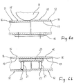
- the Figure 6a illustrates this.
- the total height of the left in Figure 6a The reproduced rail segment 11 is slightly lower than the total height of the other rail segment 12 due to the manufacturing process. This results in at least a slight step in the joint area when both rail segments 11, 12 are fastened with their underside on a common bracket 14 fixed to the frame.
- the running surfaces 15 having a height offset are driven over, the distribution vehicle reproduced on the basis of its roller 8 vibrates.
- the situation is different with the in Figure 6b schematically reproduced measures.
- the adjacent rail segments 11, 12 are screwed onto the frame of the warehouse, but their total height is not supported on a bracket 14 that is fixed to the frame. Instead, the rail segments 11, 12 are aligned with one another by means of a pressure distribution strip 20.
- the pressure distribution strip 20 is supported with its straight, flat top against the underside of that profile section 16 of the rail segments 11, 12, which forms the running surface 15 on its top.
- the arrangement is such that the pressure distributor bar 20 is supported with part of its length against the rear side 17 facing away from the running surface 15 on the first rail segment 11, and with the remaining part of its length against the rear side 17 facing away from the running surface 15 on the second rail segment 12 . Therefore, only the sheet metal thickness of the profile section 16 is located between the pressure distribution bar 20 and the running surface 15 their pure material thickness, d. H. their sheet thickness concerns.
- the pressure distribution bar 20 with its straight, flat upper side therefore forms a "smoothing" compensating element which, when pressure is exerted, is supported from below against that profile section 16 which forms the running surface 15 on its upper side.
- the prerequisite for the effectiveness of the pressure distribution strip 20 is that its upper side is essentially flat and of a width that is at most equal to the width of the running surface 15, and that it is subject to an upward pressure load.
- This pressure load is achieved by pressure transmission elements 21, which are shown in FIG Figure 6b are only shown schematically by means of vertical pressure arrows. Concrete exemplary embodiments of the pressure transmission elements 21 are described below with reference to FIG Figures 2 to 5 reproduced.
- the two rail segments 11, 12 are of C-shaped profile cross-section, as in FIG Fig. 1 reproduced.
- the two rail segments 11, 12 are screwed directly onto the vertical support 1 of the frame 3 by means of screws 27.
- the console 30 is z. B. of S-shaped cross-section. It is of such a length in the longitudinal direction of the rail that part of its length is in the rail segment 11 and the remaining part of its length is in the rail segment 12.
- the console 30 is a short profile which is firmly connected to both rail segments 11, 12.
- the console 30 is connected to profile sections 31, which protrude downward from the profile sections 16 forming the running surface 15, by a first screw connection 30A.
- the console 30 is connected to the vertical profile sections 13, which are fastened to the frame 3, by a second screw connection 30B.
- the screw connections 30A, 30B are made by means of screws which pass through openings in the bracket 30, in the profile sections 31 and 13 of the rail segments and also through openings in the support 1.
- the console 30 seated in both rail segments 11, 12 forms with the rail segments 11, 12 an assembly that is solid but not necessarily completely rigid.
- the bracket 30 forms the required abutment 22 when the pressure distribution strip 20 is pressed against the profile section 16.
- a screw 40 serves as the adjustable pressure transmission element 21 on each of the rail segments 11, 12. Its thread is screwed to a corresponding internal thread on the bracket 30.
- the end face of each screw 40 is supported in order to exert pressure against the pressure distribution strip 20, which in the exemplary embodiment has an underside, which extends parallel to the top.
- the pressure distribution bar 20 is designed here as an elongated cuboid.
- the internal thread on the console 30 serves as an abutment 22.
- a lower profile section 36 of the segments 11, 12 is provided as an extension of the screw 40 with an opening 37 for passing the tool through.
- the console 30 can be of the same length as the pressure distribution bar 20 or of greater or lesser length. However, both the console 30 and the pressure distribution strip 20 are shorter than the rail segments 11, 12, since they only extend over the end regions of the rail segments 11, 12.
- the console 30 extends partly in one, partly in the other rail segment.
- two brackets that are only half as long, the first bracket being arranged and fastened only in the first rail segment 11 and the second bracket only in the second rail segment 12.
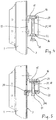
- Fig. 4 a second, significantly simplified embodiment is shown.
- the rail segments 11, 12 are here each screwed to the frame 3, closed rectangular hollow profiles.
- the pressure transmission elements 21 supported against the common pressure distribution bar 20 are in turn screws 40.
- the abutment 22 fixed to the frame is not located on an additional bracket, but on the lower profile section 36 of the rectangular profile.
- a nut is welded on the inside of the profile section 36, on which the internal thread for adjusting the screw 40 is located.
- the screws 40 press with their other end from below against the common pressure distribution strip 20, which in turn is supported on the rear side 17 of those profile sections 16 which form the running surfaces 15 at the top.
- a third embodiment is shown. It is characterized by simple assembly and the fact that the overall height of the rail segments including the bracket 30 serving as an abutment is relatively low.
- the rail segments 11, 12 are here from a cross section open at the bottom.
- a short horizontal profile section 31A of the segments forms a support on which the console 30 is supported with its one longitudinal edge, while the console 30 is suspended in the vertical support 1 at its other longitudinal edge.
- the console 30 is therefore mounted without screw connections.
- the support 1 is provided with corresponding openings.
- the console 30 is provided with an internal thread which forms the actual abutment 22 and in which the screw 40 serving as a pressure transmission element 21 engages with its external thread.
- the console 30 optionally extends over the end areas of both rail segments 11, 12, or there are two separate consoles 30, one console only being located in one rail segment 11 and the other console only in the other rail segment 12. But again, the pressure distribution bar 20 is continuous, as in FIG Figure 6b reproduced.
Landscapes
- Engineering & Computer Science (AREA)
- Mechanical Engineering (AREA)
- Warehouses Or Storage Devices (AREA)
- Fittings On The Vehicle Exterior For Carrying Loads, And Devices For Holding Or Mounting Articles (AREA)
Priority Applications (1)
| Application Number | Priority Date | Filing Date | Title |
|---|---|---|---|
| PL20155142T PL3699112T3 (pl) | 2019-02-21 | 2020-02-03 | Magazyn towarowy, w szczególności magazyn typu shuttle |
Applications Claiming Priority (1)
| Application Number | Priority Date | Filing Date | Title |
|---|---|---|---|
| DE102019104372.7A DE102019104372A1 (de) | 2019-02-21 | 2019-02-21 | Warenlager, insbesondere Shuttlelager |
Publications (2)
| Publication Number | Publication Date |
|---|---|
| EP3699112A1 true EP3699112A1 (fr) | 2020-08-26 |
| EP3699112B1 EP3699112B1 (fr) | 2021-10-06 |
Family
ID=69467417
Family Applications (1)
| Application Number | Title | Priority Date | Filing Date |
|---|---|---|---|
| EP20155142.1A Active EP3699112B1 (fr) | 2019-02-21 | 2020-02-03 | Entrepôt, en particulier entrepôt navette |
Country Status (7)
| Country | Link |
|---|---|
| US (1) | US11286112B2 (fr) |
| EP (1) | EP3699112B1 (fr) |
| CA (1) | CA3070165A1 (fr) |
| DE (1) | DE102019104372A1 (fr) |
| DK (1) | DK3699112T3 (fr) |
| ES (1) | ES2902492T3 (fr) |
| PL (1) | PL3699112T3 (fr) |
Cited By (1)
| Publication number | Priority date | Publication date | Assignee | Title |
|---|---|---|---|---|
| WO2022248333A1 (fr) * | 2021-05-27 | 2022-12-01 | Autostore Technology AS | Joint de dilatation pour relier une première région et une deuxième région d'un système de rails |
Families Citing this family (5)
| Publication number | Priority date | Publication date | Assignee | Title |
|---|---|---|---|---|
| US12091245B2 (en) * | 2020-04-30 | 2024-09-17 | Murata Machinery, Ltd. | Traveling platform, and automatic warehouse |
| ES3009333T3 (en) * | 2020-10-27 | 2025-03-26 | Stow Int N V | An automated small parts shuttle racking system |
| DE102021110715A1 (de) * | 2021-04-27 | 2022-10-27 | Nedcon B.V. | Warenlager mit befahrbaren Gassen |
| US11772893B1 (en) * | 2021-11-23 | 2023-10-03 | Amazon Technologies, Inc. | Transition components for gaps in shuttle rails |
| DE102022119000A1 (de) | 2022-07-28 | 2024-02-08 | Nedcon B.V. | Warenlager zum Ein- und Auslagern von auf Ladungsträgern angeordneten Waren oder Warengebinden |
Citations (4)
| Publication number | Priority date | Publication date | Assignee | Title |
|---|---|---|---|---|
| US20140346130A1 (en) * | 2013-05-23 | 2014-11-27 | Milton Merl & Associates, Inc. | Storage rack divider kit and apparatus |
| DE102014114496A1 (de) | 2014-10-07 | 2016-04-07 | Bito-Lagertechnik Bittmann Gmbh | Regallager mit Laufschienen |
| DE102014114978A1 (de) * | 2014-10-15 | 2016-04-21 | Bito-Lagertechnik Bittmann Gmbh | Regallager |
| EP3321216A1 (fr) | 2016-11-10 | 2018-05-16 | BITO-Lagertechnik Bittmann GmbH | Palier de navette |
Family Cites Families (3)
| Publication number | Priority date | Publication date | Assignee | Title |
|---|---|---|---|---|
| IT1294287B1 (it) * | 1997-07-30 | 1999-03-24 | Fata Automation | Magazzino a celle con carri di trasporto a movimentazione idropneumatica |
| AT511162A1 (de) * | 2011-02-08 | 2012-09-15 | Tgw Mechanics Gmbh | Regallagersystem |
| AT511623B1 (de) * | 2011-07-08 | 2016-01-15 | Tgw Mechanics Gmbh | Regallagersystem |
-
2019
- 2019-02-21 DE DE102019104372.7A patent/DE102019104372A1/de not_active Withdrawn
-
2020
- 2020-01-29 CA CA3070165A patent/CA3070165A1/fr active Pending
- 2020-02-03 DK DK20155142.1T patent/DK3699112T3/da active
- 2020-02-03 ES ES20155142T patent/ES2902492T3/es active Active
- 2020-02-03 EP EP20155142.1A patent/EP3699112B1/fr active Active
- 2020-02-03 PL PL20155142T patent/PL3699112T3/pl unknown
- 2020-02-10 US US16/785,711 patent/US11286112B2/en active Active
Patent Citations (4)
| Publication number | Priority date | Publication date | Assignee | Title |
|---|---|---|---|---|
| US20140346130A1 (en) * | 2013-05-23 | 2014-11-27 | Milton Merl & Associates, Inc. | Storage rack divider kit and apparatus |
| DE102014114496A1 (de) | 2014-10-07 | 2016-04-07 | Bito-Lagertechnik Bittmann Gmbh | Regallager mit Laufschienen |
| DE102014114978A1 (de) * | 2014-10-15 | 2016-04-21 | Bito-Lagertechnik Bittmann Gmbh | Regallager |
| EP3321216A1 (fr) | 2016-11-10 | 2018-05-16 | BITO-Lagertechnik Bittmann GmbH | Palier de navette |
Cited By (2)
| Publication number | Priority date | Publication date | Assignee | Title |
|---|---|---|---|---|
| WO2022248333A1 (fr) * | 2021-05-27 | 2022-12-01 | Autostore Technology AS | Joint de dilatation pour relier une première région et une deuxième région d'un système de rails |
| EP4347437A1 (fr) * | 2021-05-27 | 2024-04-10 | Autostore Technology As | Joint de dilatation pour relier une première région et une deuxième région d'un système de rails |
Also Published As
| Publication number | Publication date |
|---|---|
| EP3699112B1 (fr) | 2021-10-06 |
| DK3699112T3 (da) | 2022-01-03 |
| US20200270059A1 (en) | 2020-08-27 |
| CA3070165A1 (fr) | 2020-08-21 |
| PL3699112T3 (pl) | 2022-02-14 |
| ES2902492T3 (es) | 2022-03-28 |
| DE102019104372A1 (de) | 2020-08-27 |
| US11286112B2 (en) | 2022-03-29 |
Similar Documents
| Publication | Publication Date | Title |
|---|---|---|
| EP3699112B1 (fr) | Entrepôt, en particulier entrepôt navette | |
| EP2850968B1 (fr) | Entrepôt de marchandise automatisé | |
| AT408090B (de) | Ausziehvorrichtung zur aufnahme von schwerlasten, insbesondere für ein lastfahrzeug, wie ein einsatzfahrzeug | |
| EP1934120B1 (fr) | Rayonnage dote d'une pluralite d'unites de rayonnage | |
| DE3229601A1 (de) | Daemmstoffbahn, insbesondere aus mineralfaserfilz, mit einer aufgeklebten kaschierung, sowie verfahren zu ihrer herstellung und verfahren zu ihrem einbau | |
| DE69422292T2 (de) | Universalträger für eine bewegliche last | |
| WO2007121952A1 (fr) | Planchette d'etagere | |
| EP3321216A1 (fr) | Palier de navette | |
| WO2022003048A1 (fr) | Entrepôt pour le stockage et la récupération de marchandises ou de lots de marchandises placés sur des supports de charge | |
| EP0572929A1 (fr) | Palette de parking | |
| EP4703299A1 (fr) | Entrepôt pour le stockage et le déstockage de marchandises ou de gerbes de marchandises disposées sur des supports de charge | |
| EP3336048B1 (fr) | Appareil de commande de rayonnage | |
| EP4461671A1 (fr) | Agencement d'étagère | |
| AT525229B1 (de) | Waage zum Wägen eines Abrollcontainers | |
| EP4330162B1 (fr) | Entrepôt de marchandises avec allées carrossables | |
| EP0935932B1 (fr) | Etagère de stockage, en particulier pour le stockage de palettes chargées | |
| DE3627841C2 (fr) | ||
| EP3974349B1 (fr) | Entrepôt de navettes | |
| EP2226272B1 (fr) | Système d'étagère | |
| DE102020120245B4 (de) | Träger für ein Kraftfahrzeug | |
| DE3503359C2 (de) | Flurförderzeug, insbesondere Stapelfahrzeug, auch als Schubmaststapler | |
| WO2024023090A1 (fr) | Entrepôt de stockage et de récupération de marchandises ou de lots de marchandises placés sur des porte-charges | |
| DE102007047439A1 (de) | Schalungsanrodnung für den Freivorbau von Brücken | |
| EP0936160A1 (fr) | Dispositif de stockage pour palettes ou des articles avec une base standardisée | |
| DE202008012966U1 (de) | Aufbau für ein Transportfahrzeug und mit einem solchen Aufbau versehener Sattelzug |
Legal Events
| Date | Code | Title | Description |
|---|---|---|---|
| PUAI | Public reference made under article 153(3) epc to a published international application that has entered the european phase |
Free format text: ORIGINAL CODE: 0009012 |
|
| STAA | Information on the status of an ep patent application or granted ep patent |
Free format text: STATUS: THE APPLICATION HAS BEEN PUBLISHED |
|
| AK | Designated contracting states |
Kind code of ref document: A1 Designated state(s): AL AT BE BG CH CY CZ DE DK EE ES FI FR GB GR HR HU IE IS IT LI LT LU LV MC MK MT NL NO PL PT RO RS SE SI SK SM TR |
|
| AX | Request for extension of the european patent |
Extension state: BA ME |
|
| STAA | Information on the status of an ep patent application or granted ep patent |
Free format text: STATUS: REQUEST FOR EXAMINATION WAS MADE |
|
| 17P | Request for examination filed |
Effective date: 20201207 |
|
| RBV | Designated contracting states (corrected) |
Designated state(s): AL AT BE BG CH CY CZ DE DK EE ES FI FR GB GR HR HU IE IS IT LI LT LU LV MC MK MT NL NO PL PT RO RS SE SI SK SM TR |
|
| GRAP | Despatch of communication of intention to grant a patent |
Free format text: ORIGINAL CODE: EPIDOSNIGR1 |
|
| STAA | Information on the status of an ep patent application or granted ep patent |
Free format text: STATUS: GRANT OF PATENT IS INTENDED |
|
| INTG | Intention to grant announced |
Effective date: 20210512 |
|
| GRAS | Grant fee paid |
Free format text: ORIGINAL CODE: EPIDOSNIGR3 |
|
| GRAA | (expected) grant |
Free format text: ORIGINAL CODE: 0009210 |
|
| STAA | Information on the status of an ep patent application or granted ep patent |
Free format text: STATUS: THE PATENT HAS BEEN GRANTED |
|
| AK | Designated contracting states |
Kind code of ref document: B1 Designated state(s): AL AT BE BG CH CY CZ DE DK EE ES FI FR GB GR HR HU IE IS IT LI LT LU LV MC MK MT NL NO PL PT RO RS SE SI SK SM TR |
|
| REG | Reference to a national code |
Ref country code: GB Ref legal event code: FG4D Free format text: NOT ENGLISH |
|
| REG | Reference to a national code |
Ref country code: CH Ref legal event code: EP Ref country code: AT Ref legal event code: REF Ref document number: 1436053 Country of ref document: AT Kind code of ref document: T Effective date: 20211015 |
|
| REG | Reference to a national code |
Ref country code: DE Ref legal event code: R096 Ref document number: 502020000232 Country of ref document: DE |
|
| REG | Reference to a national code |
Ref country code: IE Ref legal event code: FG4D Free format text: LANGUAGE OF EP DOCUMENT: GERMAN |
|
| REG | Reference to a national code |
Ref country code: FI Ref legal event code: FGE |
|
| REG | Reference to a national code |
Ref country code: DK Ref legal event code: T3 Effective date: 20211223 |
|
| REG | Reference to a national code |
Ref country code: SE Ref legal event code: TRGR |
|
| REG | Reference to a national code |
Ref country code: NL Ref legal event code: FP |
|
| REG | Reference to a national code |
Ref country code: DE Ref legal event code: R082 Ref document number: 502020000232 Country of ref document: DE Representative=s name: JANKE SCHOLL PATENTANWAELTE PARTG MBB, DE |
|
| REG | Reference to a national code |
Ref country code: LT Ref legal event code: MG9D |
|
| REG | Reference to a national code |
Ref country code: NO Ref legal event code: T2 Effective date: 20211006 |
|
| REG | Reference to a national code |
Ref country code: ES Ref legal event code: FG2A Ref document number: 2902492 Country of ref document: ES Kind code of ref document: T3 Effective date: 20220328 |
|
| PG25 | Lapsed in a contracting state [announced via postgrant information from national office to epo] |
Ref country code: RS Free format text: LAPSE BECAUSE OF FAILURE TO SUBMIT A TRANSLATION OF THE DESCRIPTION OR TO PAY THE FEE WITHIN THE PRESCRIBED TIME-LIMIT Effective date: 20211006 Ref country code: LT Free format text: LAPSE BECAUSE OF FAILURE TO SUBMIT A TRANSLATION OF THE DESCRIPTION OR TO PAY THE FEE WITHIN THE PRESCRIBED TIME-LIMIT Effective date: 20211006 Ref country code: BG Free format text: LAPSE BECAUSE OF FAILURE TO SUBMIT A TRANSLATION OF THE DESCRIPTION OR TO PAY THE FEE WITHIN THE PRESCRIBED TIME-LIMIT Effective date: 20220106 |
|
| PG25 | Lapsed in a contracting state [announced via postgrant information from national office to epo] |
Ref country code: IS Free format text: LAPSE BECAUSE OF FAILURE TO SUBMIT A TRANSLATION OF THE DESCRIPTION OR TO PAY THE FEE WITHIN THE PRESCRIBED TIME-LIMIT Effective date: 20220206 Ref country code: PT Free format text: LAPSE BECAUSE OF FAILURE TO SUBMIT A TRANSLATION OF THE DESCRIPTION OR TO PAY THE FEE WITHIN THE PRESCRIBED TIME-LIMIT Effective date: 20220207 Ref country code: LV Free format text: LAPSE BECAUSE OF FAILURE TO SUBMIT A TRANSLATION OF THE DESCRIPTION OR TO PAY THE FEE WITHIN THE PRESCRIBED TIME-LIMIT Effective date: 20211006 Ref country code: HR Free format text: LAPSE BECAUSE OF FAILURE TO SUBMIT A TRANSLATION OF THE DESCRIPTION OR TO PAY THE FEE WITHIN THE PRESCRIBED TIME-LIMIT Effective date: 20211006 Ref country code: GR Free format text: LAPSE BECAUSE OF FAILURE TO SUBMIT A TRANSLATION OF THE DESCRIPTION OR TO PAY THE FEE WITHIN THE PRESCRIBED TIME-LIMIT Effective date: 20220107 |
|
| REG | Reference to a national code |
Ref country code: DE Ref legal event code: R097 Ref document number: 502020000232 Country of ref document: DE |
|
| PG25 | Lapsed in a contracting state [announced via postgrant information from national office to epo] |
Ref country code: SM Free format text: LAPSE BECAUSE OF FAILURE TO SUBMIT A TRANSLATION OF THE DESCRIPTION OR TO PAY THE FEE WITHIN THE PRESCRIBED TIME-LIMIT Effective date: 20211006 Ref country code: SK Free format text: LAPSE BECAUSE OF FAILURE TO SUBMIT A TRANSLATION OF THE DESCRIPTION OR TO PAY THE FEE WITHIN THE PRESCRIBED TIME-LIMIT Effective date: 20211006 Ref country code: RO Free format text: LAPSE BECAUSE OF FAILURE TO SUBMIT A TRANSLATION OF THE DESCRIPTION OR TO PAY THE FEE WITHIN THE PRESCRIBED TIME-LIMIT Effective date: 20211006 Ref country code: EE Free format text: LAPSE BECAUSE OF FAILURE TO SUBMIT A TRANSLATION OF THE DESCRIPTION OR TO PAY THE FEE WITHIN THE PRESCRIBED TIME-LIMIT Effective date: 20211006 Ref country code: CZ Free format text: LAPSE BECAUSE OF FAILURE TO SUBMIT A TRANSLATION OF THE DESCRIPTION OR TO PAY THE FEE WITHIN THE PRESCRIBED TIME-LIMIT Effective date: 20211006 |
|
| PLBE | No opposition filed within time limit |
Free format text: ORIGINAL CODE: 0009261 |
|
| STAA | Information on the status of an ep patent application or granted ep patent |
Free format text: STATUS: NO OPPOSITION FILED WITHIN TIME LIMIT |
|
| 26N | No opposition filed |
Effective date: 20220707 |
|
| PG25 | Lapsed in a contracting state [announced via postgrant information from national office to epo] |
Ref country code: MC Free format text: LAPSE BECAUSE OF FAILURE TO SUBMIT A TRANSLATION OF THE DESCRIPTION OR TO PAY THE FEE WITHIN THE PRESCRIBED TIME-LIMIT Effective date: 20211006 |
|
| PG25 | Lapsed in a contracting state [announced via postgrant information from national office to epo] |
Ref country code: LU Free format text: LAPSE BECAUSE OF NON-PAYMENT OF DUE FEES Effective date: 20220203 Ref country code: AL Free format text: LAPSE BECAUSE OF FAILURE TO SUBMIT A TRANSLATION OF THE DESCRIPTION OR TO PAY THE FEE WITHIN THE PRESCRIBED TIME-LIMIT Effective date: 20211006 |
|
| PG25 | Lapsed in a contracting state [announced via postgrant information from national office to epo] |
Ref country code: SI Free format text: LAPSE BECAUSE OF FAILURE TO SUBMIT A TRANSLATION OF THE DESCRIPTION OR TO PAY THE FEE WITHIN THE PRESCRIBED TIME-LIMIT Effective date: 20211006 |
|
| PG25 | Lapsed in a contracting state [announced via postgrant information from national office to epo] |
Ref country code: IE Free format text: LAPSE BECAUSE OF NON-PAYMENT OF DUE FEES Effective date: 20220203 |
|
| PG25 | Lapsed in a contracting state [announced via postgrant information from national office to epo] |
Ref country code: IT Free format text: LAPSE BECAUSE OF FAILURE TO SUBMIT A TRANSLATION OF THE DESCRIPTION OR TO PAY THE FEE WITHIN THE PRESCRIBED TIME-LIMIT Effective date: 20211006 |
|
| PG25 | Lapsed in a contracting state [announced via postgrant information from national office to epo] |
Ref country code: MK Free format text: LAPSE BECAUSE OF FAILURE TO SUBMIT A TRANSLATION OF THE DESCRIPTION OR TO PAY THE FEE WITHIN THE PRESCRIBED TIME-LIMIT Effective date: 20211006 Ref country code: CY Free format text: LAPSE BECAUSE OF FAILURE TO SUBMIT A TRANSLATION OF THE DESCRIPTION OR TO PAY THE FEE WITHIN THE PRESCRIBED TIME-LIMIT Effective date: 20211006 |
|
| PG25 | Lapsed in a contracting state [announced via postgrant information from national office to epo] |
Ref country code: HU Free format text: LAPSE BECAUSE OF FAILURE TO SUBMIT A TRANSLATION OF THE DESCRIPTION OR TO PAY THE FEE WITHIN THE PRESCRIBED TIME-LIMIT; INVALID AB INITIO Effective date: 20200203 |
|
| PG25 | Lapsed in a contracting state [announced via postgrant information from national office to epo] |
Ref country code: TR Free format text: LAPSE BECAUSE OF FAILURE TO SUBMIT A TRANSLATION OF THE DESCRIPTION OR TO PAY THE FEE WITHIN THE PRESCRIBED TIME-LIMIT Effective date: 20211006 |
|
| PG25 | Lapsed in a contracting state [announced via postgrant information from national office to epo] |
Ref country code: MT Free format text: LAPSE BECAUSE OF FAILURE TO SUBMIT A TRANSLATION OF THE DESCRIPTION OR TO PAY THE FEE WITHIN THE PRESCRIBED TIME-LIMIT Effective date: 20211006 |
|
| REG | Reference to a national code |
Ref country code: CH Ref legal event code: U11 Free format text: ST27 STATUS EVENT CODE: U-0-0-U10-U11 (AS PROVIDED BY THE NATIONAL OFFICE) Effective date: 20260301 |
|
| PGFP | Annual fee paid to national office [announced via postgrant information from national office to epo] |
Ref country code: NL Payment date: 20260218 Year of fee payment: 7 |
|
| PGFP | Annual fee paid to national office [announced via postgrant information from national office to epo] |
Ref country code: SE Payment date: 20260218 Year of fee payment: 7 |
|
| PGFP | Annual fee paid to national office [announced via postgrant information from national office to epo] |
Ref country code: GB Payment date: 20260219 Year of fee payment: 7 |
|
| PGFP | Annual fee paid to national office [announced via postgrant information from national office to epo] |
Ref country code: ES Payment date: 20260319 Year of fee payment: 7 |
|
| PGFP | Annual fee paid to national office [announced via postgrant information from national office to epo] |
Ref country code: NO Payment date: 20260217 Year of fee payment: 7 Ref country code: DK Payment date: 20260217 Year of fee payment: 7 Ref country code: DE Payment date: 20260205 Year of fee payment: 7 |
|
| PGFP | Annual fee paid to national office [announced via postgrant information from national office to epo] |
Ref country code: AT Payment date: 20260216 Year of fee payment: 7 |
|
| PGFP | Annual fee paid to national office [announced via postgrant information from national office to epo] |
Ref country code: BE Payment date: 20260218 Year of fee payment: 7 Ref country code: FI Payment date: 20260217 Year of fee payment: 7 |
|
| PGFP | Annual fee paid to national office [announced via postgrant information from national office to epo] |
Ref country code: FR Payment date: 20260219 Year of fee payment: 7 |
|
| PGFP | Annual fee paid to national office [announced via postgrant information from national office to epo] |
Ref country code: CH Payment date: 20260301 Year of fee payment: 7 |
|
| PGFP | Annual fee paid to national office [announced via postgrant information from national office to epo] |
Ref country code: PL Payment date: 20260203 Year of fee payment: 7 |