EP3715539B1 - Mehrwegeventil mit einer mehrzahl von gekoppelten membranventilen - Google Patents
Mehrwegeventil mit einer mehrzahl von gekoppelten membranventilen Download PDFInfo
- Publication number
- EP3715539B1 EP3715539B1 EP20153225.6A EP20153225A EP3715539B1 EP 3715539 B1 EP3715539 B1 EP 3715539B1 EP 20153225 A EP20153225 A EP 20153225A EP 3715539 B1 EP3715539 B1 EP 3715539B1
- Authority
- EP
- European Patent Office
- Prior art keywords
- valve
- membrane
- control
- liquid
- outlet
- Prior art date
- Legal status (The legal status is an assumption and is not a legal conclusion. Google has not performed a legal analysis and makes no representation as to the accuracy of the status listed.)
- Active
Links
Images
Classifications
-
- F—MECHANICAL ENGINEERING; LIGHTING; HEATING; WEAPONS; BLASTING
- F16—ENGINEERING ELEMENTS AND UNITS; GENERAL MEASURES FOR PRODUCING AND MAINTAINING EFFECTIVE FUNCTIONING OF MACHINES OR INSTALLATIONS; THERMAL INSULATION IN GENERAL
- F16K—VALVES; TAPS; COCKS; ACTUATING-FLOATS; DEVICES FOR VENTING OR AERATING
- F16K11/00—Multiple-way valves, e.g. mixing valves; Pipe fittings incorporating such valves
- F16K11/02—Multiple-way valves, e.g. mixing valves; Pipe fittings incorporating such valves with all movable sealing faces moving as one unit
- F16K11/022—Multiple-way valves, e.g. mixing valves; Pipe fittings incorporating such valves with all movable sealing faces moving as one unit comprising a deformable member
-
- F—MECHANICAL ENGINEERING; LIGHTING; HEATING; WEAPONS; BLASTING
- F16—ENGINEERING ELEMENTS AND UNITS; GENERAL MEASURES FOR PRODUCING AND MAINTAINING EFFECTIVE FUNCTIONING OF MACHINES OR INSTALLATIONS; THERMAL INSULATION IN GENERAL
- F16K—VALVES; TAPS; COCKS; ACTUATING-FLOATS; DEVICES FOR VENTING OR AERATING
- F16K11/00—Multiple-way valves, e.g. mixing valves; Pipe fittings incorporating such valves
- F16K11/02—Multiple-way valves, e.g. mixing valves; Pipe fittings incorporating such valves with all movable sealing faces moving as one unit
- F16K11/04—Multiple-way valves, e.g. mixing valves; Pipe fittings incorporating such valves with all movable sealing faces moving as one unit comprising only lift valves
- F16K11/044—Multiple-way valves, e.g. mixing valves; Pipe fittings incorporating such valves with all movable sealing faces moving as one unit comprising only lift valves with movable valve members positioned between valve seats
- F16K11/0445—Bath/shower selectors
-
- F—MECHANICAL ENGINEERING; LIGHTING; HEATING; WEAPONS; BLASTING
- F16—ENGINEERING ELEMENTS AND UNITS; GENERAL MEASURES FOR PRODUCING AND MAINTAINING EFFECTIVE FUNCTIONING OF MACHINES OR INSTALLATIONS; THERMAL INSULATION IN GENERAL
- F16K—VALVES; TAPS; COCKS; ACTUATING-FLOATS; DEVICES FOR VENTING OR AERATING
- F16K31/00—Actuating devices; Operating means; Releasing devices
- F16K31/12—Actuating devices; Operating means; Releasing devices actuated by fluid
- F16K31/36—Actuating devices; Operating means; Releasing devices actuated by fluid in which fluid from the circuit is constantly supplied to the fluid motor
- F16K31/38—Actuating devices; Operating means; Releasing devices actuated by fluid in which fluid from the circuit is constantly supplied to the fluid motor in which the fluid works directly on both sides of the fluid motor, one side being connected by means of a restricted passage and the motor being actuated by operating a discharge from that side
- F16K31/385—Actuating devices; Operating means; Releasing devices actuated by fluid in which fluid from the circuit is constantly supplied to the fluid motor in which the fluid works directly on both sides of the fluid motor, one side being connected by means of a restricted passage and the motor being actuated by operating a discharge from that side the fluid acting on a diaphragm
-
- E—FIXED CONSTRUCTIONS
- E03—WATER SUPPLY; SEWERAGE
- E03C—DOMESTIC PLUMBING INSTALLATIONS FOR FRESH WATER OR WASTE WATER; SINKS
- E03C2201/00—Details, devices or methods not otherwise provided for
- E03C2201/30—Diverter valves in faucets or taps
Definitions
- the present invention relates to a multi-way valve for a sanitary fitting.
- sanitary fittings are used to provide a liquid as required, for example in showers, bathtubs, sinks or washbasins.
- multi-way valves with a liquid inlet and a plurality of liquid outlets, with which a liquid can be selectively supplied to a specific liquid outlet of the sanitary fitting.
- a tub outlet of a bathtub can be connected to a first liquid outlet of the multi-way valve and a hand shower can be connected to a second liquid outlet of the multi-way valve.
- the changeover between the individual liquid drains of the multi-way valve or between the individual liquid outlets of the sanitary fitting is carried out in the known multi-way valves by sluggish push/pull valves whose actuating forces are also dependent on the liquid pressure of the liquid flowing into the liquid inlet.
- DE202016003311U1 discloses a multi-way valve according to the preamble of claim 1.
- the object of the invention is therefore to at least partially solve the problems described with reference to the prior art and in particular to specify a multi-way valve which can be actuated with low actuating forces and independently of the liquid pressure of the inflowing liquid.
- the multi-way valve can be connected to a sanitary fitting, for example, via hose lines and/or pipelines.
- Sanitary fittings are used for needs-based provision a liquid, in particular water, for example in showers, bathtubs, sinks or washbasins.
- the multi-way valve can be arranged at least partially concealed or at least partially in a wall or a support.
- the multi-way valve comprises a housing with at least one inlet via which the multi-way valve can be connected to a liquid source, for example a public liquid supply network.
- a mixing valve or a mixing cartridge can be connected upstream of the at least one inlet, with which a cold water with a cold water temperature and a hot water with a hot water temperature can be mixed to form a mixed water with a desired mixed water temperature.
- the cold water temperature is in particular a maximum of 25° C. (Celsius), preferably 1° C. to 25° C., particularly preferably 5° C. to 20° C. and/or the hot water temperature is in particular a maximum of 90° C., preferably 25° C. to 90° C. more preferably 55°C to 65°C.
- the housing can be at least partially made of plastic and/or metal, such as brass.
- the housing also has at least one first outlet and at least one second outlet for the liquid.
- the at least one first outlet and the at least one second outlet can be connected to different liquid outlets, for example a tub outlet or a hand shower, in particular via hose lines and/or pipelines.
- the liquid flowing in via the at least one inlet can be fed through the housing to at least one first diaphragm valve and at least one second diaphragm valve.
- inlet channels and/or inlet chambers can be formed in the housing.
- the at least one first outlet of the multi-way valve can be controlled by the at least one first membrane valve and the at least one second outlet of the multi-way valve can be controlled by the at least one second membrane valve. This means in particular that the at least one first outlet can be (fully) closed or opened by the at least one first membrane valve and the at least one second outlet can be (completely) closed or opened by the at least one second membrane valve.
- the at least one first membrane valve comprises a first membrane and a first counter-pressure chamber connected to the at least one inlet
- the at least one second membrane valve comprises a second membrane and a second back-pressure chamber connected to the at least one inlet.
- the at least one first membrane valve and the at least one second membrane valve can be controlled by a (common and/or single) controller.
- the control comprises at least one first control channel with a first control valve and at least one second control channel with a second control valve.
- the at least one first control channel connects the first counter-pressure chamber of the at least one first membrane valve, bypassing the first membrane, to the at least one first outlet, and the at least one second control channel connects the second counter-pressure chamber of the at least one second membrane valve, bypassing the second membrane, to the at least one second outlet .
- the liquid can flow from the inflow channels and/or inflow chambers of the housing via a balancing hole in the membranes of the membrane valves and/or other components of the shower head into the back pressure chamber of the membrane valves, so that the liquid has the same liquid pressure on both sides of the membranes. Since the membranes delimit the counter-pressure chambers with a larger area than the inflow channels and/or inflow chambers of the liquid guide, the force on the membranes resulting from the liquid pressure of the liquid in the back-pressure chambers is greater than that from the liquid pressure of the liquid in the inflow channels and/or inflow chambers resulting power. As a result, the membranes are pressed onto a valve seat so that the membrane valves are closed.
- a control channel leads from the counter-pressure chambers to one of the control valves.
- the control valves can be, for example, electrically operable valves, solenoid valves or manually operable valves.
- the control valves can be arranged in the multi-way valve or outside of the multi-way valve, for example in a wall be. If the control valves are located outside of the multi-way valve, the control ducts can be designed at least partially as (flexible) hose lines. Opening the control valves allows the liquid to flow out of the back-pressure chambers via the control channels, so that the liquid pressure in the back-pressure chambers drops. As a result, the membranes are lifted off the membrane seat so that the membrane valves open.
- control channels can be designed larger or with a larger diameter than the compensating bores.
- the multi-way valve also includes a coupling for coupling the at least one first membrane of the at least one first membrane valve to the at least one second membrane of the at least one second membrane valve, so that a closing movement of the at least one first membrane causes an opening movement of the at least one second membrane.
- the coupling is in particular a mechanical element that connects the first membrane and the second membrane and/or that can be moved with the first membrane and the second membrane.
- the coupling can be formed with a (possibly one-piece) separate component that interacts (directly) with both membranes and can be designed in particular in the form of a pin or rod.
- the multi-way valve can be actuated with low actuation forces and independently of the liquid pressure of the inflowing liquid.
- the multi-way valve can have a spring, by the spring force of which the at least one second membrane valve can be closed. If no liquid flows into the multi-way valve, for example because an upstream shut-off valve is closed and the multi-way valve is therefore (essentially) pressureless, the problem can arise that both the at least one first diaphragm valve and the at least one second diaphragm valve are not completely closed. When the shut-off valve is opened, liquid can therefore initially flow out both via the at least one first outlet and via the at least one second outlet. However, it is often desired that the same drain or drains are always open when the shut-off valve is opened. For example, the bath spout should often be activated first by default, with no liquid coming out of the hand shower.
- the spring can be used in particular to implement a resetting function of the multiway valve, by means of which the multiway valve can be reset to a defined initial state when no liquid is flowing in via the at least one inlet, ie the multiway valve is (essentially) depressurized.
- the second membrane of the at least one second membrane valve is (additionally) closed with the spring force of the spring, in particular when no liquid flows to the multi-way valve.
- the spring force of the spring is therefore directed in particular in the direction of a closed position of the second membrane.
- the spring force of the spring can press the second membrane in the direction of a valve seat.
- the spring force counteracts an opening movement of the second membrane, which can have an unfavorable effect on the opening behavior of the at least one second membrane valve.
- this is prevented by the coupling of the first membrane to the second membrane, because a closing force of the first membrane counteracts at least partially the spring force of the spring via the coupling.
- the opening and closing membranes as opponents can be mechanically coupled by the coupling in such a way that the respective closing force and the opening force interact and overcome the spring force.
- the spring thus implements an immediately acting restoring function and ensures that either the at least one first diaphragm valve or the at least one second diaphragm valve is (fully) open.
- the multi-way valve is therefore intrinsically safe.
- the at least one first membrane valve can be opened by the spring force of the spring.
- the spring force can be transmitted in particular via the coupling to the first membrane of the at least one first membrane valve.
- the spring can be mounted on the coupling.
- the spring can in particular be designed in the manner of a helical spring.
- the coupling can in particular run through the spring.
- the coupling can be located (essentially only) in the area of the first and second counterflow chambers. It is also possible that the spring is located in only one of the two counterflow chambers.
- the at least one first membrane valve and the at least one second membrane valve can be arranged mirror-symmetrically to one another.
- the coupling can be mounted in the housing so that it can be moved (axially, i.e. in particular only back and forth in one direction). This means in particular that the coupling is movably guided through the housing.
- the coupling can be moved in the housing, in particular along its longitudinal axis, if this has a pin or rod-like shape.
- the coupling can be movably mounted in a partition wall (of the housing) between the at least one first diaphragm valve and the at least one second diaphragm valve.
- first control valve or the second control valve can be open.
- first control valve and the second control valve such be coupled that (exclusively or only at any time) either the first control valve or the second control valve is open.
- the controller can include a movable control element with which the first control valve and the second control valve can be operated in unison.
- the movable control element can be a control disc, for example.
- the movable control element can be adjusted by a user of the multi-way valve.
- the control element can be movably attached to the housing.
- the control element can be attached to the housing in a rotatable, displaceable and/or pressable manner.
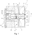
- the 1 shows a multi-way valve 1 in a sectional view.
- the multi-way valve 1 has a housing 2 with an inlet 3 via which a liquid can be fed to the multi-way valve 1 .
- a first membrane valve 6 with a first membrane 7 and a second membrane valve 9 with a second membrane 10 are arranged in the housing 1 .
- the liquid flows from the inlet 3 into an annular first inlet chamber 21 and an annular second inlet chamber 22.
- the annular first inlet chamber 21 conducts the liquid to the first membrane valve 6 and the annular second inlet chamber 22 to the second membrane valve 9.
- the liquid flows from the first inlet chamber 21 through a first compensation bore 23 in the first membrane 7 into a first counter-pressure chamber 8 and from the second inlet chamber 22 through a second compensation bore 24 in the second membrane 10 into a second Back pressure chamber 11.
- the first back pressure chamber 8 is located on a side of the first membrane 7 opposite the first inlet chamber 21 and the second back pressure chamber 24 is on a side of the second membrane 10 opposite the second inlet chamber 22.
- the first membrane 7 and the second membrane 10 are above a coupling 17 coupled to each other.
- the coupling 17 is rod-shaped here and is attached to the first membrane 7 at a first longitudinal end and to the second membrane 10 at a second longitudinal end.
- the coupling 17 is movably mounted along its longitudinal axis by a partition wall 19 between the first membrane valve 6 and the second membrane valve 9 . A movement or movement forces can thus be transmitted between the first membrane 7 and the second membrane 8 .
- the opening for the coupling 17 formed for this purpose in the partition 19 is sealed with a seal 27 so that no liquid can flow between the counter-pressure chambers 8, 9 via the opening.
- the multi-way valve 1 is in the 1 shown in an initial state and a state after a reset, respectively.
- the multi-way valve 1 has a spring 18 which is mounted on the coupling 17 and is supported on the partition wall 19 and the second membrane 10 .
- the spring 18 is designed here in the manner of a compression spring and presses the second membrane 10 in the direction of the closed position of the second membrane 10 shown here and the first membrane 7 via the coupling 17 in the direction of the open position of the first membrane 7 shown here Open position of the first membrane 7, the first membrane 7 is lifted from an annular first valve seat 25, so that a first outlet 4 of the multi-way valve 1 is open.
- the first valve seat 25 is formed at a longitudinal end of the first drain 4 .
- the liquid can flow from the first inlet chamber 21 directly into the first outlet 5 via the first valve seat 25 .
- the second membrane 10 In the closed position of the second membrane 10, the second membrane 10 is in contact with an annular second valve seat 26, so that a second outlet 5 of the multi-way valve 1 is closed.
- the second valve seat 26 is formed at a longitudinal end of the second drain 5 .
- the spring 18 keeps the position of the first membrane 7 and the second membrane 10 stable when the liquid supply via the inlet 3 is activated, so that the first outlet 4 remains (completely) open and the second outlet 5 (completely) closed.
- the same liquid pressure prevails in the second inlet chamber 22 and the second counter-pressure chamber 11 .
- the second membrane 10 delimits the second back-pressure chamber 11 with a larger area than the second inlet chamber 22, the force on the second membrane 10 resulting from the liquid pressure of the liquid in the second back-pressure chamber 11 is greater than that from the liquid pressure of the liquid in the second Inlet chamber 22 resulting force.
- the second membrane 10 is pressed onto the annular second valve seat 26 .
- the first membrane valve 6 and the second membrane valve 9 can be controlled by a common controller 12 .
- the controller 12 comprises a first control channel 13 with a first control valve 14 and a second control channel 15 with a second control valve 16.
- the first control channel 13 connects the first counter-pressure chamber 8, bypassing the first membrane 7, to the first outlet 4 and the second control channel 15 to the second counter-pressure chamber 11 bypassing the second membrane 10 with the second outlet 5.
- the first control valve 14 and the second control valve 16 are formed here by a control element 20 that is adjustably mounted on the housing 2. In the position of the control element 20 shown here, the first control valve 14 is open and the second control valve 16 is closed. When the control element 20 is adjusted (upward here), the first control valve 14 is closed and the second control valve 16 is opened.
- the opening of the second control valve 16 allows liquid to flow out of the second counter-pressure chamber 11 via the second control channel 16 into the second outlet 5, so that the pressure of the liquid in the second counter-pressure chamber 11 drops.
- the pressure of the liquid in the first counter-pressure chamber 8 increases due to the closing of the second control valve 16 because no more liquid can drain from the first counter-pressure chamber 8 via the first control channel 13 into the first outlet 4 can.
- the first membrane 7 and the second membrane 10 together generate a force that counteracts the spring force of the spring 18, so that the first membrane 7 is pressed onto the first valve seat 25 and the second membrane 10 is lifted from the second valve seat 26.
- the multi-way valve 1 can also be switched against the spring force of the spring 18, for which the force of a single membrane 7, 10 would not be sufficient.
- Either the first sequence 4 or the second sequence 5 can be activated via the controller 12 . If the liquid supply is deactivated via the inlet 3, the multi-way valve 1 or the first membrane 7 of the first membrane valve 6 and the second membrane 10 of the second membrane valve 9 are switched back into the reset to initial position.
- the first diaphragm valve 6 and the second diaphragm valve 9 are identical in the embodiment variant shown here and are mirror-symmetrical to one another. The description of the first membrane valve and the second membrane valve can therefore be related to the respective other membrane valve.
- a multi-way valve can be actuated with low actuating forces and independently of the liquid pressure of the inflowing liquid.
Landscapes
- Engineering & Computer Science (AREA)
- General Engineering & Computer Science (AREA)
- Mechanical Engineering (AREA)
- Multiple-Way Valves (AREA)
Description
- Die vorliegende Erfindung betrifft ein Mehrwegeventil für eine Sanitärarmatur. Solche Sanitärarmaturen dienen der bedarfsgerechten Bereitstellung einer Flüssigkeit zum Beispiel an Duschen, Badewannen, Spülbecken oder Waschbecken.
- Bekannte sind Mehrwegeventile mit einem Flüssigkeitszulauf und einer Mehrzahl von Flüssigkeitsabläufen, mit denen eine Flüssigkeit wahlweise einem bestimmten Flüssigkeitsauslauf der Sanitärarmatur zuführbar ist. Beispielsweise kann ein Wannenauslauf einer Badewanne mit einem ersten Flüssigkeitsablauf des Mehrwegeventils und eine Handbrause mit einem zweiten Flüssigkeitsablauf des Mehrwegeventils verbunden sein. Die Umstellung zwischen den einzelnen Flüssigkeitsabläufen des Mehrwegeventils bzw. zwischen den einzelnen Flüssigkeitsausläufen der Sanitärarmatur erfolgt bei den bekannten Mehrwegeventilen durch schwergängige Zug-/Druckventile, deren Betätigungskräfte zudem vom Flüssigkeitsdruck der in den Flüssigkeitszulauf einströmenden Flüssigkeit abhängig sind.
DE202016003311U1 offenbart ein Mehrwegeventil gemäß dem Oberbegriff des Anspruchs 1. - Aufgabe der Erfindung ist es daher, die mit Bezug auf den Stand der Technik geschilderten Probleme zumindest teilweise zu lösen und insbesondere ein Mehrwegeventil anzugeben, das mit geringen Betätigungskräften und unabhängig vom Flüssigkeitsdruck der zuströmenden Flüssigkeit betätigbar ist.
- Diese Aufgaben werden gelöst mit einem Mehrwegeventil gemäß den Merkmalen des unabhängigen Patentanspruchs. Weitere vorteilhafte Ausgestaltungen der Erfindung sind in den abhängigen Patentansprüchen angegeben. Es ist darauf hinzuweisen, dass die in den abhängigen Patentansprüchen einzeln aufgeführten Merkmale in beliebiger technologisch sinnvoller Weise miteinander kombiniert werden können und weitere Ausgestaltungen der Erfindung definieren. Darüber hinaus werden die in den Patentansprüchen angegebenen Merkmale in der Beschreibung näher präzisiert und erläutert, wobei weitere bevorzugte Ausgestaltungen der Erfindung dargestellt werden.
- Hierzu trägt ein Mehrwegeventil für eine Sanitärarmatur bei, die zumindest die folgenden Komponenten aufweist:
- ein Gehäuse mit zumindest einem Zulauf, zumindest einem ersten Ablauf und zumindest einem zweiten Ablauf;
- zumindest ein erstes Membranventil zum Steuern (Öffnen und Schließen) des zumindest einen ersten Ablaufs, wobei das zumindest eine erste Membranventil eine erste Membran und eine mit dem zumindest einen Zulauf verbundene erste Gegendruckkammer aufweist;
- zumindest ein zweites Membranventil zum Steuern (Öffnen und Schließen) des zumindest einen zweiten Ablaufs, wobei das zumindest eine zweite Membranventil eine zweite Membran und eine mit dem zumindest einen Zulauf verbundene zweite Gegendruckkammer aufweist;
- eine Steuerung zum Steuern (Betätigen) des zumindest einen ersten Membranventils und des zumindest einen zweiten Membranventils, wobei die Steuerung zumindest einen ersten Steuerkanal mit einem ersten Steuerventil und zumindest einen zweiten Steuerkanal mit einem zweiten Steuerventil aufweist und wobei der zumindest eine erste Steuerkanal die erste Gegendruckkammer des zumindest einen ersten Membranventils unter Umgehung der ersten Membran mit dem zumindest einen ersten Ablauf und der zumindest eine zweite Steuerkanal die zweite Gegendruckkammer des zumindest einen zweiten Membranventils unter Umgehung der zweiten Membran mit dem zumindest einen zweiten Ablauf verbindet; und
- eine Kopplung zum Koppeln der ersten Membran mit der zweiten Membran, sodass eine Schließbewegung der ersten Membran eine Öffnungsbewegung der zweiten Membran bewirkt.
- Das Mehrwegeventil ist beispielsweise über Schlauchleitungen und/oder Rohrleitungen mit einer Sanitärarmatur verbindbar. Sanitärarmaturen dienen der bedarfsgerechten Bereitstellung einer Flüssigkeit, insbesondere Wasser, an beispielsweise Duschen, Badewannen, Spülbecken oder Waschbecken. Das Mehrwegeventil kann insbesondere zumindest teilweise unter Putz bzw. zumindest teilweise in einer Wand oder einem Träger angeordnet sein.
- Das Mehrwegeventil umfasst ein Gehäuse mit zumindest einem Zulauf, über den das Mehrwegeventil an eine Flüssigkeitsquelle, zum Beispiel ein öffentliches Flüssigkeitsversorgungsnetz, anschließbar ist. Dem zumindest einen Zulauf kann ein Mischventil oder eine Mischkartusche vorgeschaltet sein, mit dem ein Kaltwasser mit einer Kaltwassertemperatur und ein Warmwasser mit einer Warmwassertemperatur zu einem Mischwasser mit einer gewünschten Mischwassertemperatur mischbar ist. Die Kaltwassertemperatur beträgt insbesondere maximal 25 °C (Celsius), bevorzugt 1 °C bis 25 °C, besonders bevorzugt 5 °C bis 20 °C und/oder die Warmwassertemperatur insbesondere maximal 90 °C, bevorzugt 25 °C bis 90 °C, besonders bevorzugt 55 °C bis 65 °C. Das Gehäuse kann zumindest teilweise aus Kunststoff und/oder Metall, wie zum Beispiel Messing, bestehen. Das Gehäuse weist zudem zumindest einen ersten Ablauf und zumindest einen zweiten Ablauf für die Flüssigkeit auf. Der zumindest eine erste Ablauf und der zumindest eine zweite Ablauf sind insbesondere über Schlauchleitungen und/oder Rohrleitungen mit verschiedenen Flüssigkeitsausläufen, beispielsweise einem Wannenauslauf oder einer Handbrause, verbindbar.
- Die über den zumindest einen Zulauf zuströmende Flüssigkeit ist durch das Gehäuse zumindest einem ersten Membranventil und zumindest einem zweiten Membranventil zuführbar. Hierzu können in dem Gehäuse Zulaufkanäle und/oder Zulaufkammern ausgebildet sein. Durch das zumindest eine erste Membranventil ist der zumindest eine erste Ablauf des Mehrwegeventils und durch das zumindest eine zweite Membranventil der zumindest eine zweite Ablauf des Mehrwegeventils steuerbar. Dies bedeutet insbesondere, dass durch das zumindest eine erste Membranventil der zumindest eine erste Ablauf und durch das zumindest eine zweite Membranventil der zumindest eine zweite Ablauf (vollständig) verschließbar oder öffenbar ist. Somit ist durch Öffnen des zumindest einen ersten Membranventils zumindest ein erster Flüssigkeitsauslauf und/oder durch Öffnen des zumindest einen zweiten Membranventils zumindest ein zweiter Flüssigkeitsauslauf aktivierbar. Das zumindest eine erste Membranventil umfasst eine erste Membran und eine mit dem zumindest einen Zulauf verbundene erste Gegendruckkammer und das zumindest eine zweite Membranventil eine zweite Membran und eine mit dem zumindest einen Zulauf verbundene zweite Gegendruckkammer.
- Das zumindest eine erste Membranventil und das zumindest eine zweite Membranventil sind durch eine (gemeinsame und/oder einzige) Steuerung steuerbar. Die Steuerung umfasst zumindest einen ersten Steuerkanal mit einem ersten Steuerventil und zumindest einen zweiten Steuerkanal mit einem zweiten Steuerventil. Der zumindest eine erste Steuerkanal verbindet die erste Gegendruckkammer des zumindest einen ersten Membranventils unter Umgehung der ersten Membran mit dem zumindest einen ersten Ablauf und der zumindest eine zweite Steuerkanal die zweite Gegendruckkammer des zumindest einen zweiten Membranventils unter Umgehung der zweiten Membran mit dem zumindest einen zweiten Ablauf.
- Die Flüssigkeit kann aus den Zulaufkanälen und/oder Zulaufkammern des Gehäuses über eine Ausgleichsbohrung in den Membranen der Membranventile und/oder sonstigen Komponenten des Brausekopfs in die Gegendruckkammer der Membranventile fließen, sodass die Flüssigkeit auf beiden Seiten der Membranen den gleichen Flüssigkeitsdruck aufweist. Da die Membranen die Gegendruckkammern mit einer größeren Fläche begrenzen als die Zulaufkanäle und/oder Zulaufkammern der Flüssigkeitsführung, ist die aus dem Flüssigkeitsdruck der Flüssigkeit in den Gegendruckkammern resultierende Kraft auf die Membranen größer als die aus dem Flüssigkeitsdruck der Flüssigkeit in den Zulaufkanälen und/oder Zulaufkammern resultierende Kraft. Hierdurch werden die Membranen auf einen Ventilsitz gedrückt, sodass die Membranventile geschlossen sind. Von den Gegendruckkammern führt (jeweils) ein Steuerkanal zu einem der Steuerventile. Bei den Steuerventilen kann es sich beispielsweise um elektrisch betätigbare Ventile, Magnetventile oder manuell betätigbare Ventile handeln. Die Steuerventile können in dem Mehrwegeventil oder außerhalb des Mehrwegeventils, beispielsweise in einer Wand, angeordnet sein. Befinden sich die Steuerventile außerhalb des Mehrwegeventils, können die Steuerkanäle zumindest teilweise als (flexible) Schlauchleitungen ausgebildet sein. Durch Öffnen der Steuerventile kann die Flüssigkeit über die Steuerkanäle aus den Gegendruckkammern abfließen, sodass der Flüssigkeitsdruck in den Gegendruckkammern sinkt. Hierdurch werden die Membrane von dem Membransitz abgehoben, sodass sich die Membranventile öffnen. Damit das Membranventil öffnet, muss der Flüssigkeitsdruck in der Gegendruckkammer durch den stationären Zustand, der sich zwischen der über die Ausgleichsöffnung nachfließenden Flüssigkeit und der über die Steuerkanäle aus der Gegendruckkammer abfließenden Flüssigkeit einstellt, stark genug abfallen. Hierzu können die Steuerkanäle größer bzw. mit einem größeren Durchmesser ausgeführt sein als die Ausgleichsbohrungen.
- Das Mehrwegeventil umfasst zudem eine Kopplung zum Koppeln der zumindest einen ersten Membran des zumindest einen ersten Membranventils mit der zumindest einen zweiten Membran des zumindest einen zweiten Membranventils, sodass eine Schließbewegung der zumindest einen ersten Membran eine Öffnungsbewegung der zumindest einen zweiten Membran bewirkt. Dies bedeutet insbesondere, dass die erste Membran mit der zweiten Membran derart mechanisch verbunden ist, dass eine Schließ- oder Öffnungsbewegung der ersten Membran eine entsprechende Gegenbewegung der zweiten Membran bewirkt. Hierdurch kann sichergestellt werden, dass entweder das zumindest eine erste Membranventil oder das zumindest eine zweite Membranventil (vollständig) geöffnet oder geschlossen ist. Bei der Kopplung handelt es sich insbesondere um ein mechanisches Element, dass die erste Membran und die zweite Membran verbindet und/oder das mit der ersten Membran und der zweiten Membran bewegbar ist. Die Kopplung kann mit einem (ggf. einstückigen) separaten Bauteil gebildet sein, das mit beiden Membranen (unmittelbar) zusammenwirkt und insbesondere stiftförmig oder stabförmig ausgebildet sein.
- Durch die Verwendung der Membranventile ist das Mehrwegeventil mit geringen Betätigungskräften und unabhängig vom Flüssigkeitsdruck der zuströmenden Flüssigkeit betätigbar.
- Das Mehrwegeventil kann eine Feder aufweisen, durch deren Federkraft das zumindest eine zweite Membranventil schließbar ist. Wenn dem Mehrwegeventil keine Flüssigkeit zufließt, weil beispielsweise ein vorgeschaltetes Absperrventil geschlossen ist und das Mehrwegeventil somit (im Wesentlichen) drucklos ist, kann das Problem bestehen, dass sowohl das zumindest eine erste Membranventil als auch das zumindest eine zweite Membranventil nicht vollständig geschlossen sind. Beim Öffnen des Absperrventils kann daher zunächst Flüssigkeit sowohl über den zumindest einen ersten Ablauf als auch über den zumindest einen zweiten Ablauf abfließen. Gewünscht ist jedoch häufig, dass beim Öffnen des Absperrventils immer der gleiche Ablauf oder die gleichen Abläufe geöffnet sind. Beispielsweise soll standardmäßig häufig zuerst der Wannenauslauf aktiviert sein, wobei aus der Handbrause keine Flüssigkeit kommen soll. Mit der Feder kann insbesondere eine Rückstellfunktion des Mehrwegeventils realisiert werden, durch die das Mehrwegeventil in einen definierten Ausgangszustand rückstellbar ist, wenn keine Flüssigkeit über den zumindest einen Zulauf zuströmt, d. h. das Mehrwegeventil insbesondere (im Wesentlichen) drucklos ist. Hierzu wird die zweite Membran des zumindest einen zweiten Membranventils (zusätzlich) mit der Federkraft der Feder verschlossen, insbesondere wenn dem Mehrwegeventil keine Flüssigkeit zufließt. Die Federkraft der Feder ist daher insbesondere in Richtung einer Schließstellung der zweiten Membran gerichtet. Weiterhin kann die Federkraft der Feder die zweite Membran in Richtung eines Ventilsitzes drücken. Die Federkraft wirkt einer Öffnungsbewegung der zweiten Membran entgegen, was sich ungünstig auf ein Öffnungsverhalten des zumindest einen zweiten Membranventils auswirken kann. Dies wird jedoch durch die Kopplung der ersten Membran mit der zweiten Membran verhindert, weil eine Schließkraft der ersten Membran über die Kopplung der Federkraft der Feder zumindest teilweise entgegenwirkt. Mit anderen Worten können die öffnenden und schließenden Membranen als Gegenspieler mechanisch durch die Kopplung so gekoppelt sein, dass die jeweilige Schließkraft und die Öffnungskraft zusammenwirken und die Federkraft überwinden. Durch die Feder wird somit eine sofort wirkende Rückstellfunktion realisiert und sichergestellt, dass entweder das zumindest eine erste Membranventil oder das zumindest eine zweite Membranventil (vollständig) geöffnet ist. Das Mehrwegeventil ist dadurch eigensicher.
- Das zumindest eine erste Membranventil kann durch die Federkraft der Feder öffenbar sein. Hierzu ist die Federkraft insbesondere über die Kopplung auf die erste Membran des zumindest einen ersten Membranventils übertragbar.
- Die Feder kann an der Kopplung gelagert sein. Die Feder kann insbesondere nach Art einer Schraubenfeder ausgebildet sein. Die Kopplung kann insbesondere durch die Feder verlaufen.
- Die Kopplung kann sich (im wesentlichen nur) im Bereich der ersten und zweiten Gegenstromkammer befinden. Es ist weiter möglich, dass sich die Feder nur in einer der beiden Gegenstromkammern befindet.
- Das zumindest eine erste Membranventil und das zumindest eine zweite Membranventil können spiegelsymmetrisch zueinander angeordnet sein.
- Die Kopplung kann in dem Gehäuse (axial, d.h. insbesondere nur in eine Richtung hin und her) bewegbar gelagert sein. Dies bedeutet insbesondere, dass die Kopplung durch das Gehäuse bewegbar geführt ist. Die Kopplung ist in dem Gehäuse insbesondere entlang ihrer Längsachse bewegbar, wenn dieses eine stift- oder stabähnliche Form aufweist.
- Die Kopplung kann in einer Trennwand (des Gehäuses) zwischen dem zumindest einen ersten Membranventil und dem zumindest einen zweiten Membranventil bewegbar gelagert sein.
- Entweder kann das erste Steuerventil oder das zweite Steuerventil geöffnet sein. Insbesondere können das erste Steuerventil und das zweite Steuerventil (mechanisch oder elektrisch) derart gekoppelt sein, dass (ausschließlich bzw. jederzeit nur) entweder das erste Steuerventil oder das zweite Steuerventil geöffnet ist.
- Die Steuerung kann ein bewegbares Steuerelement umfassen, mit dem das erste Steuerventil und das zweite Steuerventil gemeinsam betätigbar sind. Bei dem bewegbaren Steuerelement kann es sich beispielsweise um eine Steuerscheibe handeln. Das bewegbare Steuerelement kann insbesondere durch einen Benutzer des Mehrwegeventils verstellbar sein.
- Das Steuerelement kann bewegbar an dem Gehäuse befestigt sein. Insbesondere kann das Steuerelement rotierbar, verschiebbar und/oder drückbar an dem Gehäuse befestigt sein.
- Die Erfindung sowie das technische Umfeld werden nachfolgend anhand der Figur näher erläutert. Es ist darauf hinzuweisen, dass die Figur eine besonders bevorzugte Ausführungsvariante der Erfindung zeigt, diese jedoch nicht darauf beschränkt ist. Es zeigt beispielhaft und schematisch:
- Fig. 1:
- ein Mehrwegeventil in einer Schnittdarstellung.
- Die
Fig. 1 zeigt ein Mehrwegeventil 1 in einer Schnittdarstellung. Das Mehrwegeventil 1 weist ein Gehäuse 2 mit einem Zulauf 3 auf, über den dem Mehrwegeventil 1 eine Flüssigkeit zuführbar ist. In dem Gehäuse 1 ist ein erstes Membranventil 6 mit einer ersten Membran 7 und ein zweites Membranventil 9 mit einer zweiten Membran 10 angeordnet. Die Flüssigkeit strömt von dem Zulauf 3 in eine ringförmige erste Zulaufkammer 21 und eine ringförmige zweite Zulaufkammer 22. Die ringförmige erste Zulaufkammer 21 leitet die Flüssigkeit zu dem ersten Membranventil 6 und die ringförmige zweite Zulaufkammer 22 zu dem zweiten Membranventil 9. Die Flüssigkeit strömt von der ersten Zulaufkammer 21 durch eine erste Ausgleichsbohrung 23 in der ersten Membran 7 in eine erste Gegendruckkammer 8 und von der zweiten Zulaufkammer 22 durch eine zweite Ausgleichsbohrung 24 in der zweiten Membran 10 in eine zweite Gegendruckkammer 11. Die erste Gegendruckkammer 8 befindet sich auf einer der ersten Zulaufkammer 21 gegenüberliegenden Seite der ersten Membran 7 und die zweite Gegendrucckammer 24 auf einer der zweiten Zulaufkammer 22 gegenüberliegenden Seite der zweiten Membran 10. Die erste Membran 7 und die zweite Membran 10 sind über eine Kopplung 17 miteinander gekoppelt. Die Kopplung 17 ist hier stabförmig ausgebildet und an einem ersten längsseitigen Ende an der ersten Membran 7 und an einem zweiten längsseitigen Ende an der zweiten Membran 10 befestigt. Weiterhin ist die Kopplung 17 entlang ihrer Längsachse durch eine Trennwand 19 zwischen dem ersten Membranventil 6 und dem zweiten Membranventil 9 bewegbar gelagert. Somit sind eine Bewegung bzw. Bewegungskräfte zwischen der ersten Membran 7 und der zweiten Membran 8 übertragbar. Die hierzu in der Trennwand 19 ausgebildete Öffnung für die Kopplung 17 ist mit einer Dichtung 27 abgedichtet, sodass über die Öffnung keine Flüssigkeit zwischen den Gegendruckkammern 8, 9 fließen kann. - Das Mehrwegeventil 1 ist in der
Fig. 1 in einem Ausgangszustand bzw. einem Zustand nach einer Rückstellung gezeigt. Zur Erreichung des Ausgangszustands nach einer Deaktivierung der Flüssigkeitszufuhr über den Zulauf 3 weist das Mehrwegeventil 1 eine Feder 18 auf, die an der Kopplung 17 gelagert ist und sich an der Trennwand 19 und der zweiten Membran 10 abstützt. Die Feder 18 ist hier nach Art einer Druckfeder ausgebildet und drückt die zweite Membran 10 in Richtung der hier gezeigten geschlossenen Stellung der zweiten Membran 10 und die erste Membran 7 über die Kopplung 17 in Richtung der hier gezeigten geöffneten Stellung der ersten Membran 7. In der geöffneten Stellung der ersten Membran 7 ist die erste Membran 7 von einem ringförmigen ersten Ventilsitz 25 abgehoben, sodass ein erster Ablauf 4 des Mehrwegeventils 1 geöffnet ist. Der erste Ventilsitz 25 ist an einem längsseitigen Ende des ersten Ablaufs 4 ausgebildet. Im geöffneten Zustand der ersten Membran 7 kann die Flüssigkeit von der ersten Zulaufkammer 21 über den ersten Ventilsitz 25 direkt in den ersten Ablauf 5 fließen. In der geschlossenen Stellung der zweiten Membran 10 liegt die zweite Membran 10 an einem ringförmigen zweiten Ventilsitz 26 an, sodass ein zweiter Ablauf 5 des Mehrwegeventils 1 geschlossen ist. Der zweite Ventilsitz 26 ist an einem längsseitigen Ende des zweiten Ablaufs 5 ausgebildet. - Durch die Feder 18 bleibt die Stellung der ersten Membran 7 und der zweiten Membran 10 bei Aktivierung der Flüssigkeitszufuhr über den Zulauf 3 stabil, sodass der erste Ablauf 4 (vollständig) geöffnet und der zweite Ablauf 5 (vollständig) geschlossen bleibt. Im geschlossenen Zustand der zweiten Membran 10 herrscht nach der Aktivierung der Flüssigkeitszufuhr über den Zulauf 3 in der zweiten Zulaufkammer 22 und der zweiten Gegendruckkammer 11 der gleiche Flüssigkeitsdruck. Da die zweite Membran 10 die zweite Gegendruckkammer 11 mit einer größeren Fläche begrenzt als die zweite Zulaufkammer 22, ist die aus dem Flüssigkeitsdruck der Flüssigkeit in der zweiten Gegendruckkammer 11 resultierende Kraft auf die zweite Membran 10 größer als die aus dem Flüssigkeitsdruck der Flüssigkeit in der zweiten Zulaufkammer 22 resultierende Kraft. Hierdurch wird die zweite Membran 10 auf den ringförmigen zweiten Ventilsitz 26 gedrückt.
- Das erste Membranventil 6 und das zweite Membranventil 9 sind durch eine gemeinsame Steuerung 12 steuerbar. Die Steuerung 12 umfasst einen ersten Steuerkanal 13 mit einem ersten Steuerventil 14 und einen zweiten Steuerkanal 15 mit einem zweiten Steuerventil 16. Der erste Steuerkanal 13 verbindet die erste Gegendruckkammer 8 unter Umgehung der ersten Membran 7 mit dem ersten Ablauf 4 und der zweite Steuerkanal 15 die zweite Gegendrucckammer 11 unter Umgehung der zweiten Membran 10 mit dem zweiten Ablauf 5. Das erste Steuerventil 14 und das zweite Steuerventil 16 werden hier durch ein Steuerelement 20 gebildet, dass an dem Gehäuse 2 verstellbar gelagert ist. In der hier gezeigten Stellung des Steuerelements 20 ist das erste Steuerventil 14 geöffnet und das zweite Steuerventil 16 geschlossen. Beim Verstellen des Steuerelements 20 (hier nach oben) wird das erste Steuerventil 14 geschlossen und das zweite Steuerventil 16 geöffnet. Durch das Öffnen des zweiten Steuerventils 16 kann Flüssigkeit von der zweiten Gegendruckkammer 11 über den zweiten Steuerkanal 16 in den zweiten Ablauf 5 abfließen, sodass der Druck der Flüssigkeit in der zweiten Gegendrucckammer 11 sinkt. Gleichzeitig steigt der Druck der Flüssigkeit in der ersten Gegendruckkammer 8 durch das Schließen des zweiten Steuerventils 16 an, weil keine Flüssigkeit mehr von der ersten Gegendruckkammer 8 über den ersten Steuerkanal 13 in den ersten Ablauf 4 ablaufen kann. Durch die geänderten Druckverhältnisse in der ersten Gegendruckkammer 8 und der zweiten Gegendruckkammer 11 erzeugen die erste Membran 7 und die zweite Membran 10 gemeinsam eine der Federkraft der Feder 18 entgegenwirkende Kraft, sodass die erste Membran 7 auf den ersten Ventilsitz 25 gedrückt und die zweite Membran 10 von dem zweiten Ventilsitz 26 abgehoben wird. Durch die doppelte Kraftwirkung der ersten Membran 7 und der zweiten Membran 10 über die Kopplung 17 kann die Umstellung des Mehrwegeventils 1 auch gegen die Federkraft der Feder 18 erfolgen, wofür die Kraft einer einzelnen Membran 7, 10 nicht ausreichen würde. Über die Steuerung 12 ist wahlweise der erste Ablauf 4 oder der zweite Ablauf 5 aktivierbar. Bei einer Deaktivierung der Flüssigkeitszufuhr über den Zulauf 3 wird das Mehrwegeventil 1 bzw. die erste Membran 7 des ersten Membranventils 6 und die zweite Membran 10 des zweiten Membranventils 9 unabhängig von der Stellung des Steuerelements 20 durch die Feder 18 und die Kopplung 17 wieder in die Ausgangsstellung zurückgestellt. Das erste Membranventil 6 und das zweite Membranventil 9 sind bei der hier gezeigten Ausführungsvariante identisch und spiegelsymmetrisch zueinander ausgebildet. Die Beschreibung des ersten Membranventils und des zweiten Membranventils kann daher auf das jeweilige andere Membranventil bezogen werden.
- Durch die vorliegende Erfindung ist ein Mehrwegeventil mit geringen Betätigungskräften und unabhängig vom Flüssigkeitsdruck der zuströmenden Flüssigkeit betätigbar.
-
- 1
- Mehrwegeventil
- 2
- Gehäuse
- 3
- Zulauf
- 4
- erster Ablauf
- 5
- zweite Ablauf
- 6
- erstes Membranventil
- 7
- erste Membran
- 8
- erste Gegendruckkammer
- 9
- zweites Membranventil
- 10
- zweite Membran
- 11
- zweite Gegendruckkammer
- 12
- Steuerung
- 13
- erster Steuerkanal
- 14
- erstes Steuerventil
- 15
- zweiter Steuerkanal
- 16
- zweites Steuerventil
- 17
- Kopplung
- 18
- Feder
- 19
- Trennwand
- 20
- Steuerelement
- 21
- erste Zulaufkammer
- 22
- zweite Zulaufkammer
- 23
- erster Ausgleichsbohrung
- 24
- zweiter Ausgleichsbohrung
- 25
- erster Ventilsitz
- 26
- zweiter Ventilsitz
- 27
- Dichtung
Claims (10)
- Mehrwegeventil (1) für eine Sanitärarmatur, zumindest aufweisend:- ein Gehäuse (2) mit zumindest einem Zulauf (3), zumindest einem ersten Ablauf (4) und zumindest einem zweiten Ablauf (5);- zumindest ein erstes Membranventil (6) zum Steuern des zumindest einen ersten Ablaufs (4), wobei das zumindest eine erste Membranventil (6) eine erste Membran (7) und eine mit dem zumindest einen Zulauf (3) verbundene erste Gegendruckkammer (8) aufweist;- zumindest ein zweites Membranventil (9) zum Steuern des zumindest einen zweiten Ablaufs (5), wobei das zumindest eine zweite Membranventil (9) eine zweite Membran (10) und eine mit dem zumindest einen Zulauf (3) verbundene zweite Gegendrucckammer (11) aufweist;- eine Steuerung (12) zum Steuern des zumindest einen ersten Membranventils (6) und des zumindest einen zweiten Membranventils (9), wobei die Steuerung (12) zumindest einen ersten Steuerkanal (13) mit einem ersten Steuerventil (14) und zumindest einen zweiten Steuerkanal (15) mit einem zweiten Steuerventil (16) aufweist und wobei der zumindest eine erste Steuerkanal (13) die erste Gegendruckkammer (8) des zumindest einen ersten Membranventils (6) unter Umgehung der ersten Membran (7) mit dem zumindest einen ersten Ablauf (4) und der zumindest eine zweite Steuerkanal (15) die zweite Gegendruckkammer (11) des zumindest einen zweiten Membranventils (9) unter Umgehung der zweiten Membran (10) mit dem zumindest einen zweiten Ablauf (5) verbindet; dadurch gekennzeichnet, dass das Mehrwegeventil (1) eine Kopplung (17) zum Koppeln der ersten Membran (7) mit der zweiten Membran (10) aufweist, sodass eine Schließbewegung der ersten Membran (7) eine Öffnungsbewegung der zweiten Membran (10) bewirkt.
- Mehrwegeventil (1) nach Patentanspruch 1, aufweisend eine Feder (18), durch deren Federkraft das zumindest eine zweite Membranventil (9) schließbar ist.
- Mehrwegeventil (2) nach Patentanspruch 2, wobei das zumindest eine erste Membranventil (6) durch die Federkraft der Feder (18) öffenbar ist.
- Mehrwegeventil (1) nach Patentanspruch 2 oder 3, wobei die Feder (18) an der Kopplung (17) gelagert ist.
- Mehrwegeventil (1) nach einem der vorhergehenden Patentansprüche, wobei das zumindest eine erste Membranventil (6) und das zumindest eine zweite Membranventil (9) spiegelsymmetrisch zueinander angeordnet sind.
- Mehrwegeventil (1) nach einem der vorhergehenden Patentansprüche, wobei die Kopplung (17) in dem Gehäuse (2) bewegbar gelagert ist.
- Mehrwegeventil (1) nach einem der vorhergehenden Patentansprüche, wobei die Kopplung (17) in einer Trennwand (19) zwischen dem zumindest einen ersten Membranventil (6) und dem zumindest einen zweiten Membranventil (9) bewegbar gelagert ist.
- Mehrwegeventil (1) nach einem der vorhergehenden Patentansprüche, wobei entweder das erste Steuerventil (14) oder das zweite Steuerventil (16) geöffnet ist.
- Mehrwegeventil (1) nach einem der vorhergehenden Patentansprüche, wobei die Steuerung (12) ein bewegbares Steuerelement (20) umfasst, mit dem das erste Steuerventil (14) und das zweite Steuerventil (16) gemeinsam betätigbar sind.
- Mehrwegeventil (1) nach Patentanspruch 9, wobei das Steuerelement (20) bewegbar an dem Gehäuse (2) befestigt ist.
Applications Claiming Priority (1)
| Application Number | Priority Date | Filing Date | Title |
|---|---|---|---|
| DE102019103601.1A DE102019103601A1 (de) | 2019-02-13 | 2019-02-13 | Mehrwegeventil mit einer Mehrzahl von gekoppelten Membranventilen |
Publications (2)
| Publication Number | Publication Date |
|---|---|
| EP3715539A1 EP3715539A1 (de) | 2020-09-30 |
| EP3715539B1 true EP3715539B1 (de) | 2022-04-13 |
Family
ID=69187725
Family Applications (1)
| Application Number | Title | Priority Date | Filing Date |
|---|---|---|---|
| EP20153225.6A Active EP3715539B1 (de) | 2019-02-13 | 2020-01-22 | Mehrwegeventil mit einer mehrzahl von gekoppelten membranventilen |
Country Status (3)
| Country | Link |
|---|---|
| EP (1) | EP3715539B1 (de) |
| DE (1) | DE102019103601A1 (de) |
| ES (1) | ES2923201T3 (de) |
Cited By (1)
| Publication number | Priority date | Publication date | Assignee | Title |
|---|---|---|---|---|
| WO2026049633A1 (en) * | 2024-09-02 | 2026-03-05 | Jets As | Liquid interface |
Family Cites Families (8)
| Publication number | Priority date | Publication date | Assignee | Title |
|---|---|---|---|---|
| US3099290A (en) * | 1961-01-31 | 1963-07-30 | Chatleff Controls Inc | Diverting valve |
| JPS4950684U (de) * | 1972-08-14 | 1974-05-04 | ||
| JPS5270428A (en) * | 1975-12-08 | 1977-06-11 | Mikuni Kogyo Co Ltd | Switching valve |
| DE7827699U1 (de) * | 1978-09-18 | 1982-04-29 | Siemens AG, 1000 Berlin und 8000 München | Zweiweg-membranventil |
| JPS57110876A (en) * | 1980-12-27 | 1982-07-09 | Isomura Kiki Kk | Fluid turn-over valve and hot water supplyer using same |
| JP2794811B2 (ja) * | 1989-08-07 | 1998-09-10 | 東陶機器株式会社 | 二方向切替弁 |
| JPH07280110A (ja) * | 1994-04-13 | 1995-10-27 | Smc Corp | 3ポート弁 |
| DE102016001975A1 (de) * | 2016-02-22 | 2017-08-24 | Neoperl Gmbh | Ventilbetätigungsvorrichtung |
-
2019
- 2019-02-13 DE DE102019103601.1A patent/DE102019103601A1/de not_active Withdrawn
-
2020
- 2020-01-22 ES ES20153225T patent/ES2923201T3/es active Active
- 2020-01-22 EP EP20153225.6A patent/EP3715539B1/de active Active
Cited By (1)
| Publication number | Priority date | Publication date | Assignee | Title |
|---|---|---|---|---|
| WO2026049633A1 (en) * | 2024-09-02 | 2026-03-05 | Jets As | Liquid interface |
Also Published As
| Publication number | Publication date |
|---|---|
| DE102019103601A1 (de) | 2020-08-13 |
| ES2923201T3 (es) | 2022-09-26 |
| EP3715539A1 (de) | 2020-09-30 |
Similar Documents
| Publication | Publication Date | Title |
|---|---|---|
| EP3115518B1 (de) | Sanitärarmatur mit zwei ventilen | |
| DE2453633A1 (de) | Thermostatische mischvorrichtung und verfahren zum regeln der temperatur | |
| DE60123112T2 (de) | Strömungsmischer | |
| DE19623104A1 (de) | Als Einhebelmischer ausgebildete Sanitärarmatur | |
| DE102012013594A1 (de) | Leitungssystem zum Transport von Flüssigkeiten | |
| EP3715539B1 (de) | Mehrwegeventil mit einer mehrzahl von gekoppelten membranventilen | |
| EP4051933B1 (de) | Ventil für eine sanitärarmatur mit einem membranventil und einem einstellbaren steuerstab | |
| EP4018047B1 (de) | Stagnationsspülventilvorrichtung | |
| EP3563207B1 (de) | Regelarmatur zur regelung des differenzdruckes und/oder des volumenstromes | |
| DE4431127A1 (de) | Sanitärventil mit einem Magnetventil | |
| EP2206939B1 (de) | Armatur | |
| WO2020043611A1 (de) | Brause für eine sanitärarmatur mit einem betätigungselement für eine mehrzahl von membranventilen | |
| EP3599399A1 (de) | Sanitärventil mit membranventil | |
| WO2014076238A1 (de) | Ventileinrichtung für ein sanitärventil | |
| DE60009972T2 (de) | Vorrichtung zum Druckausgleich von kaltem und warmem Wasser und Armatur, insbesondere themostatische Armatur, mit einer solchen Ausgleichvorrichtung | |
| EP2870393B1 (de) | Leitungssystem zum transport von flüssigkeiten | |
| DE102019002246A1 (de) | Mehrwegeventil mit einer Mehrzahl von Membranventilen | |
| EP1039189B1 (de) | Steuervorrichtung für ein Schaltorgan | |
| DE102016010386A1 (de) | Warmwasserversorgungssystem zum zentralen Versorgen eines Verbrauchernetzes | |
| EP4286614B1 (de) | Sanitärarmatur mit absperrventilen | |
| EP3786499A1 (de) | Sanitärventil mit keramischen dichtelementen | |
| DE19622171C1 (de) | Vorrichtung zur Steuerung der Wasserausgabe an einem Waschbecken | |
| DE2653926A1 (de) | Magnetventil | |
| EP2463445A1 (de) | Sanitäre Ventileinrichtung | |
| EP1386205B1 (de) | Vorrichtung zum Regeln bzw.Steuern des Flusses von zwei fliessfähigen Medien und Verwendung der Vorrichtung in der Sanitärtechnik |
Legal Events
| Date | Code | Title | Description |
|---|---|---|---|
| PUAI | Public reference made under article 153(3) epc to a published international application that has entered the european phase |
Free format text: ORIGINAL CODE: 0009012 |
|
| STAA | Information on the status of an ep patent application or granted ep patent |
Free format text: STATUS: THE APPLICATION HAS BEEN PUBLISHED |
|
| AK | Designated contracting states |
Kind code of ref document: A1 Designated state(s): AL AT BE BG CH CY CZ DE DK EE ES FI FR GB GR HR HU IE IS IT LI LT LU LV MC MK MT NL NO PL PT RO RS SE SI SK SM TR |
|
| AX | Request for extension of the european patent |
Extension state: BA ME |
|
| STAA | Information on the status of an ep patent application or granted ep patent |
Free format text: STATUS: REQUEST FOR EXAMINATION WAS MADE |
|
| 17P | Request for examination filed |
Effective date: 20210311 |
|
| RBV | Designated contracting states (corrected) |
Designated state(s): AL AT BE BG CH CY CZ DE DK EE ES FI FR GB GR HR HU IE IS IT LI LT LU LV MC MK MT NL NO PL PT RO RS SE SI SK SM TR |
|
| RAP3 | Party data changed (applicant data changed or rights of an application transferred) |
Owner name: GROHE AG |
|
| GRAP | Despatch of communication of intention to grant a patent |
Free format text: ORIGINAL CODE: EPIDOSNIGR1 |
|
| STAA | Information on the status of an ep patent application or granted ep patent |
Free format text: STATUS: GRANT OF PATENT IS INTENDED |
|
| INTG | Intention to grant announced |
Effective date: 20211108 |
|
| GRAS | Grant fee paid |
Free format text: ORIGINAL CODE: EPIDOSNIGR3 |
|
| GRAA | (expected) grant |
Free format text: ORIGINAL CODE: 0009210 |
|
| STAA | Information on the status of an ep patent application or granted ep patent |
Free format text: STATUS: THE PATENT HAS BEEN GRANTED |
|
| AK | Designated contracting states |
Kind code of ref document: B1 Designated state(s): AL AT BE BG CH CY CZ DE DK EE ES FI FR GB GR HR HU IE IS IT LI LT LU LV MC MK MT NL NO PL PT RO RS SE SI SK SM TR |
|
| REG | Reference to a national code |
Ref country code: GB Ref legal event code: FG4D Free format text: NOT ENGLISH |
|
| REG | Reference to a national code |
Ref country code: CH Ref legal event code: EP |
|
| REG | Reference to a national code |
Ref country code: DE Ref legal event code: R096 Ref document number: 502020000914 Country of ref document: DE |
|
| REG | Reference to a national code |
Ref country code: IE Ref legal event code: FG4D Free format text: LANGUAGE OF EP DOCUMENT: GERMAN |
|
| REG | Reference to a national code |
Ref country code: AT Ref legal event code: REF Ref document number: 1483506 Country of ref document: AT Kind code of ref document: T Effective date: 20220515 |
|
| REG | Reference to a national code |
Ref country code: LT Ref legal event code: MG9D |
|
| REG | Reference to a national code |
Ref country code: NL Ref legal event code: MP Effective date: 20220413 |
|
| REG | Reference to a national code |
Ref country code: ES Ref legal event code: FG2A Ref document number: 2923201 Country of ref document: ES Kind code of ref document: T3 Effective date: 20220926 |
|
| PG25 | Lapsed in a contracting state [announced via postgrant information from national office to epo] |
Ref country code: NL Free format text: LAPSE BECAUSE OF FAILURE TO SUBMIT A TRANSLATION OF THE DESCRIPTION OR TO PAY THE FEE WITHIN THE PRESCRIBED TIME-LIMIT Effective date: 20220413 |
|
| PG25 | Lapsed in a contracting state [announced via postgrant information from national office to epo] |
Ref country code: SE Free format text: LAPSE BECAUSE OF FAILURE TO SUBMIT A TRANSLATION OF THE DESCRIPTION OR TO PAY THE FEE WITHIN THE PRESCRIBED TIME-LIMIT Effective date: 20220413 Ref country code: PT Free format text: LAPSE BECAUSE OF FAILURE TO SUBMIT A TRANSLATION OF THE DESCRIPTION OR TO PAY THE FEE WITHIN THE PRESCRIBED TIME-LIMIT Effective date: 20220816 Ref country code: NO Free format text: LAPSE BECAUSE OF FAILURE TO SUBMIT A TRANSLATION OF THE DESCRIPTION OR TO PAY THE FEE WITHIN THE PRESCRIBED TIME-LIMIT Effective date: 20220713 Ref country code: LT Free format text: LAPSE BECAUSE OF FAILURE TO SUBMIT A TRANSLATION OF THE DESCRIPTION OR TO PAY THE FEE WITHIN THE PRESCRIBED TIME-LIMIT Effective date: 20220413 Ref country code: HR Free format text: LAPSE BECAUSE OF FAILURE TO SUBMIT A TRANSLATION OF THE DESCRIPTION OR TO PAY THE FEE WITHIN THE PRESCRIBED TIME-LIMIT Effective date: 20220413 Ref country code: GR Free format text: LAPSE BECAUSE OF FAILURE TO SUBMIT A TRANSLATION OF THE DESCRIPTION OR TO PAY THE FEE WITHIN THE PRESCRIBED TIME-LIMIT Effective date: 20220714 Ref country code: FI Free format text: LAPSE BECAUSE OF FAILURE TO SUBMIT A TRANSLATION OF THE DESCRIPTION OR TO PAY THE FEE WITHIN THE PRESCRIBED TIME-LIMIT Effective date: 20220413 Ref country code: BG Free format text: LAPSE BECAUSE OF FAILURE TO SUBMIT A TRANSLATION OF THE DESCRIPTION OR TO PAY THE FEE WITHIN THE PRESCRIBED TIME-LIMIT Effective date: 20220713 |
|
| PG25 | Lapsed in a contracting state [announced via postgrant information from national office to epo] |
Ref country code: RS Free format text: LAPSE BECAUSE OF FAILURE TO SUBMIT A TRANSLATION OF THE DESCRIPTION OR TO PAY THE FEE WITHIN THE PRESCRIBED TIME-LIMIT Effective date: 20220413 Ref country code: PL Free format text: LAPSE BECAUSE OF FAILURE TO SUBMIT A TRANSLATION OF THE DESCRIPTION OR TO PAY THE FEE WITHIN THE PRESCRIBED TIME-LIMIT Effective date: 20220413 Ref country code: LV Free format text: LAPSE BECAUSE OF FAILURE TO SUBMIT A TRANSLATION OF THE DESCRIPTION OR TO PAY THE FEE WITHIN THE PRESCRIBED TIME-LIMIT Effective date: 20220413 Ref country code: IS Free format text: LAPSE BECAUSE OF FAILURE TO SUBMIT A TRANSLATION OF THE DESCRIPTION OR TO PAY THE FEE WITHIN THE PRESCRIBED TIME-LIMIT Effective date: 20220813 |
|
| REG | Reference to a national code |
Ref country code: DE Ref legal event code: R097 Ref document number: 502020000914 Country of ref document: DE |
|
| PG25 | Lapsed in a contracting state [announced via postgrant information from national office to epo] |
Ref country code: SM Free format text: LAPSE BECAUSE OF FAILURE TO SUBMIT A TRANSLATION OF THE DESCRIPTION OR TO PAY THE FEE WITHIN THE PRESCRIBED TIME-LIMIT Effective date: 20220413 Ref country code: SK Free format text: LAPSE BECAUSE OF FAILURE TO SUBMIT A TRANSLATION OF THE DESCRIPTION OR TO PAY THE FEE WITHIN THE PRESCRIBED TIME-LIMIT Effective date: 20220413 Ref country code: RO Free format text: LAPSE BECAUSE OF FAILURE TO SUBMIT A TRANSLATION OF THE DESCRIPTION OR TO PAY THE FEE WITHIN THE PRESCRIBED TIME-LIMIT Effective date: 20220413 Ref country code: EE Free format text: LAPSE BECAUSE OF FAILURE TO SUBMIT A TRANSLATION OF THE DESCRIPTION OR TO PAY THE FEE WITHIN THE PRESCRIBED TIME-LIMIT Effective date: 20220413 Ref country code: DK Free format text: LAPSE BECAUSE OF FAILURE TO SUBMIT A TRANSLATION OF THE DESCRIPTION OR TO PAY THE FEE WITHIN THE PRESCRIBED TIME-LIMIT Effective date: 20220413 Ref country code: CZ Free format text: LAPSE BECAUSE OF FAILURE TO SUBMIT A TRANSLATION OF THE DESCRIPTION OR TO PAY THE FEE WITHIN THE PRESCRIBED TIME-LIMIT Effective date: 20220413 |
|
| PLBE | No opposition filed within time limit |
Free format text: ORIGINAL CODE: 0009261 |
|
| STAA | Information on the status of an ep patent application or granted ep patent |
Free format text: STATUS: NO OPPOSITION FILED WITHIN TIME LIMIT |
|
| 26N | No opposition filed |
Effective date: 20230116 |
|
| PG25 | Lapsed in a contracting state [announced via postgrant information from national office to epo] |
Ref country code: AL Free format text: LAPSE BECAUSE OF FAILURE TO SUBMIT A TRANSLATION OF THE DESCRIPTION OR TO PAY THE FEE WITHIN THE PRESCRIBED TIME-LIMIT Effective date: 20220413 |
|
| PG25 | Lapsed in a contracting state [announced via postgrant information from national office to epo] |
Ref country code: SI Free format text: LAPSE BECAUSE OF FAILURE TO SUBMIT A TRANSLATION OF THE DESCRIPTION OR TO PAY THE FEE WITHIN THE PRESCRIBED TIME-LIMIT Effective date: 20220413 |
|
| P01 | Opt-out of the competence of the unified patent court (upc) registered |
Effective date: 20230526 |
|
| REG | Reference to a national code |
Ref country code: CH Ref legal event code: PL |
|
| PG25 | Lapsed in a contracting state [announced via postgrant information from national office to epo] |
Ref country code: LU Free format text: LAPSE BECAUSE OF NON-PAYMENT OF DUE FEES Effective date: 20230122 |
|
| REG | Reference to a national code |
Ref country code: BE Ref legal event code: MM Effective date: 20230131 |
|
| PG25 | Lapsed in a contracting state [announced via postgrant information from national office to epo] |
Ref country code: LI Free format text: LAPSE BECAUSE OF NON-PAYMENT OF DUE FEES Effective date: 20230131 Ref country code: CH Free format text: LAPSE BECAUSE OF NON-PAYMENT OF DUE FEES Effective date: 20230131 |
|
| PG25 | Lapsed in a contracting state [announced via postgrant information from national office to epo] |
Ref country code: BE Free format text: LAPSE BECAUSE OF NON-PAYMENT OF DUE FEES Effective date: 20230131 |
|
| PG25 | Lapsed in a contracting state [announced via postgrant information from national office to epo] |
Ref country code: IE Free format text: LAPSE BECAUSE OF NON-PAYMENT OF DUE FEES Effective date: 20230122 |
|
| PG25 | Lapsed in a contracting state [announced via postgrant information from national office to epo] |
Ref country code: MC Free format text: LAPSE BECAUSE OF FAILURE TO SUBMIT A TRANSLATION OF THE DESCRIPTION OR TO PAY THE FEE WITHIN THE PRESCRIBED TIME-LIMIT Effective date: 20220413 |
|
| PG25 | Lapsed in a contracting state [announced via postgrant information from national office to epo] |
Ref country code: MC Free format text: LAPSE BECAUSE OF FAILURE TO SUBMIT A TRANSLATION OF THE DESCRIPTION OR TO PAY THE FEE WITHIN THE PRESCRIBED TIME-LIMIT Effective date: 20220413 |
|
| GBPC | Gb: european patent ceased through non-payment of renewal fee |
Effective date: 20240122 |
|
| PG25 | Lapsed in a contracting state [announced via postgrant information from national office to epo] |
Ref country code: GB Free format text: LAPSE BECAUSE OF NON-PAYMENT OF DUE FEES Effective date: 20240122 |
|
| PG25 | Lapsed in a contracting state [announced via postgrant information from national office to epo] |
Ref country code: GB Free format text: LAPSE BECAUSE OF NON-PAYMENT OF DUE FEES Effective date: 20240122 |
|
| PG25 | Lapsed in a contracting state [announced via postgrant information from national office to epo] |
Ref country code: BG Free format text: LAPSE BECAUSE OF FAILURE TO SUBMIT A TRANSLATION OF THE DESCRIPTION OR TO PAY THE FEE WITHIN THE PRESCRIBED TIME-LIMIT Effective date: 20220413 |
|
| PG25 | Lapsed in a contracting state [announced via postgrant information from national office to epo] |
Ref country code: BG Free format text: LAPSE BECAUSE OF FAILURE TO SUBMIT A TRANSLATION OF THE DESCRIPTION OR TO PAY THE FEE WITHIN THE PRESCRIBED TIME-LIMIT Effective date: 20220413 |
|
| PGFP | Annual fee paid to national office [announced via postgrant information from national office to epo] |
Ref country code: AT Payment date: 20250417 Year of fee payment: 5 |
|
| PG25 | Lapsed in a contracting state [announced via postgrant information from national office to epo] |
Ref country code: CY Free format text: LAPSE BECAUSE OF FAILURE TO SUBMIT A TRANSLATION OF THE DESCRIPTION OR TO PAY THE FEE WITHIN THE PRESCRIBED TIME-LIMIT; INVALID AB INITIO Effective date: 20200122 |
|
| PG25 | Lapsed in a contracting state [announced via postgrant information from national office to epo] |
Ref country code: HU Free format text: LAPSE BECAUSE OF FAILURE TO SUBMIT A TRANSLATION OF THE DESCRIPTION OR TO PAY THE FEE WITHIN THE PRESCRIBED TIME-LIMIT; INVALID AB INITIO Effective date: 20200122 |
|
| PG25 | Lapsed in a contracting state [announced via postgrant information from national office to epo] |
Ref country code: TR Free format text: LAPSE BECAUSE OF FAILURE TO SUBMIT A TRANSLATION OF THE DESCRIPTION OR TO PAY THE FEE WITHIN THE PRESCRIBED TIME-LIMIT Effective date: 20220413 |
|
| REG | Reference to a national code |
Ref country code: AT Ref legal event code: MM01 Ref document number: 1483506 Country of ref document: AT Kind code of ref document: T Effective date: 20250122 |
|
| PGFP | Annual fee paid to national office [announced via postgrant information from national office to epo] |
Ref country code: ES Payment date: 20260219 Year of fee payment: 7 |
|
| PGFP | Annual fee paid to national office [announced via postgrant information from national office to epo] |
Ref country code: DE Payment date: 20260115 Year of fee payment: 7 |
|
| PG25 | Lapsed in a contracting state [announced via postgrant information from national office to epo] |
Ref country code: AT Free format text: LAPSE BECAUSE OF NON-PAYMENT OF DUE FEES Effective date: 20250122 |
|
| PGFP | Annual fee paid to national office [announced via postgrant information from national office to epo] |
Ref country code: IT Payment date: 20260116 Year of fee payment: 7 |
|
| PGFP | Annual fee paid to national office [announced via postgrant information from national office to epo] |
Ref country code: FR Payment date: 20260114 Year of fee payment: 7 |