EP3715539B1 - Soupape à plusieurs voies dotée d'une pluralité de soupapes à membrane couplées - Google Patents
Soupape à plusieurs voies dotée d'une pluralité de soupapes à membrane couplées Download PDFInfo
- Publication number
- EP3715539B1 EP3715539B1 EP20153225.6A EP20153225A EP3715539B1 EP 3715539 B1 EP3715539 B1 EP 3715539B1 EP 20153225 A EP20153225 A EP 20153225A EP 3715539 B1 EP3715539 B1 EP 3715539B1
- Authority
- EP
- European Patent Office
- Prior art keywords
- valve
- membrane
- control
- liquid
- outlet
- Prior art date
- Legal status (The legal status is an assumption and is not a legal conclusion. Google has not performed a legal analysis and makes no representation as to the accuracy of the status listed.)
- Active
Links
Images
Classifications
-
- F—MECHANICAL ENGINEERING; LIGHTING; HEATING; WEAPONS; BLASTING
- F16—ENGINEERING ELEMENTS AND UNITS; GENERAL MEASURES FOR PRODUCING AND MAINTAINING EFFECTIVE FUNCTIONING OF MACHINES OR INSTALLATIONS; THERMAL INSULATION IN GENERAL
- F16K—VALVES; TAPS; COCKS; ACTUATING-FLOATS; DEVICES FOR VENTING OR AERATING
- F16K11/00—Multiple-way valves, e.g. mixing valves; Pipe fittings incorporating such valves
- F16K11/02—Multiple-way valves, e.g. mixing valves; Pipe fittings incorporating such valves with all movable sealing faces moving as one unit
- F16K11/022—Multiple-way valves, e.g. mixing valves; Pipe fittings incorporating such valves with all movable sealing faces moving as one unit comprising a deformable member
-
- F—MECHANICAL ENGINEERING; LIGHTING; HEATING; WEAPONS; BLASTING
- F16—ENGINEERING ELEMENTS AND UNITS; GENERAL MEASURES FOR PRODUCING AND MAINTAINING EFFECTIVE FUNCTIONING OF MACHINES OR INSTALLATIONS; THERMAL INSULATION IN GENERAL
- F16K—VALVES; TAPS; COCKS; ACTUATING-FLOATS; DEVICES FOR VENTING OR AERATING
- F16K11/00—Multiple-way valves, e.g. mixing valves; Pipe fittings incorporating such valves
- F16K11/02—Multiple-way valves, e.g. mixing valves; Pipe fittings incorporating such valves with all movable sealing faces moving as one unit
- F16K11/04—Multiple-way valves, e.g. mixing valves; Pipe fittings incorporating such valves with all movable sealing faces moving as one unit comprising only lift valves
- F16K11/044—Multiple-way valves, e.g. mixing valves; Pipe fittings incorporating such valves with all movable sealing faces moving as one unit comprising only lift valves with movable valve members positioned between valve seats
- F16K11/0445—Bath/shower selectors
-
- F—MECHANICAL ENGINEERING; LIGHTING; HEATING; WEAPONS; BLASTING
- F16—ENGINEERING ELEMENTS AND UNITS; GENERAL MEASURES FOR PRODUCING AND MAINTAINING EFFECTIVE FUNCTIONING OF MACHINES OR INSTALLATIONS; THERMAL INSULATION IN GENERAL
- F16K—VALVES; TAPS; COCKS; ACTUATING-FLOATS; DEVICES FOR VENTING OR AERATING
- F16K31/00—Actuating devices; Operating means; Releasing devices
- F16K31/12—Actuating devices; Operating means; Releasing devices actuated by fluid
- F16K31/36—Actuating devices; Operating means; Releasing devices actuated by fluid in which fluid from the circuit is constantly supplied to the fluid motor
- F16K31/38—Actuating devices; Operating means; Releasing devices actuated by fluid in which fluid from the circuit is constantly supplied to the fluid motor in which the fluid works directly on both sides of the fluid motor, one side being connected by means of a restricted passage and the motor being actuated by operating a discharge from that side
- F16K31/385—Actuating devices; Operating means; Releasing devices actuated by fluid in which fluid from the circuit is constantly supplied to the fluid motor in which the fluid works directly on both sides of the fluid motor, one side being connected by means of a restricted passage and the motor being actuated by operating a discharge from that side the fluid acting on a diaphragm
-
- E—FIXED CONSTRUCTIONS
- E03—WATER SUPPLY; SEWERAGE
- E03C—DOMESTIC PLUMBING INSTALLATIONS FOR FRESH WATER OR WASTE WATER; SINKS
- E03C2201/00—Details, devices or methods not otherwise provided for
- E03C2201/30—Diverter valves in faucets or taps
Definitions
- the present invention relates to a multi-way valve for a sanitary fitting.
- sanitary fittings are used to provide a liquid as required, for example in showers, bathtubs, sinks or washbasins.
- multi-way valves with a liquid inlet and a plurality of liquid outlets, with which a liquid can be selectively supplied to a specific liquid outlet of the sanitary fitting.
- a tub outlet of a bathtub can be connected to a first liquid outlet of the multi-way valve and a hand shower can be connected to a second liquid outlet of the multi-way valve.
- the changeover between the individual liquid drains of the multi-way valve or between the individual liquid outlets of the sanitary fitting is carried out in the known multi-way valves by sluggish push/pull valves whose actuating forces are also dependent on the liquid pressure of the liquid flowing into the liquid inlet.
- DE202016003311U1 discloses a multi-way valve according to the preamble of claim 1.
- the object of the invention is therefore to at least partially solve the problems described with reference to the prior art and in particular to specify a multi-way valve which can be actuated with low actuating forces and independently of the liquid pressure of the inflowing liquid.
- the multi-way valve can be connected to a sanitary fitting, for example, via hose lines and/or pipelines.
- Sanitary fittings are used for needs-based provision a liquid, in particular water, for example in showers, bathtubs, sinks or washbasins.
- the multi-way valve can be arranged at least partially concealed or at least partially in a wall or a support.
- the multi-way valve comprises a housing with at least one inlet via which the multi-way valve can be connected to a liquid source, for example a public liquid supply network.
- a mixing valve or a mixing cartridge can be connected upstream of the at least one inlet, with which a cold water with a cold water temperature and a hot water with a hot water temperature can be mixed to form a mixed water with a desired mixed water temperature.
- the cold water temperature is in particular a maximum of 25° C. (Celsius), preferably 1° C. to 25° C., particularly preferably 5° C. to 20° C. and/or the hot water temperature is in particular a maximum of 90° C., preferably 25° C. to 90° C. more preferably 55°C to 65°C.
- the housing can be at least partially made of plastic and/or metal, such as brass.
- the housing also has at least one first outlet and at least one second outlet for the liquid.
- the at least one first outlet and the at least one second outlet can be connected to different liquid outlets, for example a tub outlet or a hand shower, in particular via hose lines and/or pipelines.
- the liquid flowing in via the at least one inlet can be fed through the housing to at least one first diaphragm valve and at least one second diaphragm valve.
- inlet channels and/or inlet chambers can be formed in the housing.
- the at least one first outlet of the multi-way valve can be controlled by the at least one first membrane valve and the at least one second outlet of the multi-way valve can be controlled by the at least one second membrane valve. This means in particular that the at least one first outlet can be (fully) closed or opened by the at least one first membrane valve and the at least one second outlet can be (completely) closed or opened by the at least one second membrane valve.
- the at least one first membrane valve comprises a first membrane and a first counter-pressure chamber connected to the at least one inlet
- the at least one second membrane valve comprises a second membrane and a second back-pressure chamber connected to the at least one inlet.
- the at least one first membrane valve and the at least one second membrane valve can be controlled by a (common and/or single) controller.
- the control comprises at least one first control channel with a first control valve and at least one second control channel with a second control valve.
- the at least one first control channel connects the first counter-pressure chamber of the at least one first membrane valve, bypassing the first membrane, to the at least one first outlet, and the at least one second control channel connects the second counter-pressure chamber of the at least one second membrane valve, bypassing the second membrane, to the at least one second outlet .
- the liquid can flow from the inflow channels and/or inflow chambers of the housing via a balancing hole in the membranes of the membrane valves and/or other components of the shower head into the back pressure chamber of the membrane valves, so that the liquid has the same liquid pressure on both sides of the membranes. Since the membranes delimit the counter-pressure chambers with a larger area than the inflow channels and/or inflow chambers of the liquid guide, the force on the membranes resulting from the liquid pressure of the liquid in the back-pressure chambers is greater than that from the liquid pressure of the liquid in the inflow channels and/or inflow chambers resulting power. As a result, the membranes are pressed onto a valve seat so that the membrane valves are closed.
- a control channel leads from the counter-pressure chambers to one of the control valves.
- the control valves can be, for example, electrically operable valves, solenoid valves or manually operable valves.
- the control valves can be arranged in the multi-way valve or outside of the multi-way valve, for example in a wall be. If the control valves are located outside of the multi-way valve, the control ducts can be designed at least partially as (flexible) hose lines. Opening the control valves allows the liquid to flow out of the back-pressure chambers via the control channels, so that the liquid pressure in the back-pressure chambers drops. As a result, the membranes are lifted off the membrane seat so that the membrane valves open.
- control channels can be designed larger or with a larger diameter than the compensating bores.
- the multi-way valve also includes a coupling for coupling the at least one first membrane of the at least one first membrane valve to the at least one second membrane of the at least one second membrane valve, so that a closing movement of the at least one first membrane causes an opening movement of the at least one second membrane.
- the coupling is in particular a mechanical element that connects the first membrane and the second membrane and/or that can be moved with the first membrane and the second membrane.
- the coupling can be formed with a (possibly one-piece) separate component that interacts (directly) with both membranes and can be designed in particular in the form of a pin or rod.
- the multi-way valve can be actuated with low actuation forces and independently of the liquid pressure of the inflowing liquid.
- the multi-way valve can have a spring, by the spring force of which the at least one second membrane valve can be closed. If no liquid flows into the multi-way valve, for example because an upstream shut-off valve is closed and the multi-way valve is therefore (essentially) pressureless, the problem can arise that both the at least one first diaphragm valve and the at least one second diaphragm valve are not completely closed. When the shut-off valve is opened, liquid can therefore initially flow out both via the at least one first outlet and via the at least one second outlet. However, it is often desired that the same drain or drains are always open when the shut-off valve is opened. For example, the bath spout should often be activated first by default, with no liquid coming out of the hand shower.
- the spring can be used in particular to implement a resetting function of the multiway valve, by means of which the multiway valve can be reset to a defined initial state when no liquid is flowing in via the at least one inlet, ie the multiway valve is (essentially) depressurized.
- the second membrane of the at least one second membrane valve is (additionally) closed with the spring force of the spring, in particular when no liquid flows to the multi-way valve.
- the spring force of the spring is therefore directed in particular in the direction of a closed position of the second membrane.
- the spring force of the spring can press the second membrane in the direction of a valve seat.
- the spring force counteracts an opening movement of the second membrane, which can have an unfavorable effect on the opening behavior of the at least one second membrane valve.
- this is prevented by the coupling of the first membrane to the second membrane, because a closing force of the first membrane counteracts at least partially the spring force of the spring via the coupling.
- the opening and closing membranes as opponents can be mechanically coupled by the coupling in such a way that the respective closing force and the opening force interact and overcome the spring force.
- the spring thus implements an immediately acting restoring function and ensures that either the at least one first diaphragm valve or the at least one second diaphragm valve is (fully) open.
- the multi-way valve is therefore intrinsically safe.
- the at least one first membrane valve can be opened by the spring force of the spring.
- the spring force can be transmitted in particular via the coupling to the first membrane of the at least one first membrane valve.
- the spring can be mounted on the coupling.
- the spring can in particular be designed in the manner of a helical spring.
- the coupling can in particular run through the spring.
- the coupling can be located (essentially only) in the area of the first and second counterflow chambers. It is also possible that the spring is located in only one of the two counterflow chambers.
- the at least one first membrane valve and the at least one second membrane valve can be arranged mirror-symmetrically to one another.
- the coupling can be mounted in the housing so that it can be moved (axially, i.e. in particular only back and forth in one direction). This means in particular that the coupling is movably guided through the housing.
- the coupling can be moved in the housing, in particular along its longitudinal axis, if this has a pin or rod-like shape.
- the coupling can be movably mounted in a partition wall (of the housing) between the at least one first diaphragm valve and the at least one second diaphragm valve.
- first control valve or the second control valve can be open.
- first control valve and the second control valve such be coupled that (exclusively or only at any time) either the first control valve or the second control valve is open.
- the controller can include a movable control element with which the first control valve and the second control valve can be operated in unison.
- the movable control element can be a control disc, for example.
- the movable control element can be adjusted by a user of the multi-way valve.
- the control element can be movably attached to the housing.
- the control element can be attached to the housing in a rotatable, displaceable and/or pressable manner.
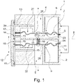
- the 1 shows a multi-way valve 1 in a sectional view.
- the multi-way valve 1 has a housing 2 with an inlet 3 via which a liquid can be fed to the multi-way valve 1 .
- a first membrane valve 6 with a first membrane 7 and a second membrane valve 9 with a second membrane 10 are arranged in the housing 1 .
- the liquid flows from the inlet 3 into an annular first inlet chamber 21 and an annular second inlet chamber 22.
- the annular first inlet chamber 21 conducts the liquid to the first membrane valve 6 and the annular second inlet chamber 22 to the second membrane valve 9.
- the liquid flows from the first inlet chamber 21 through a first compensation bore 23 in the first membrane 7 into a first counter-pressure chamber 8 and from the second inlet chamber 22 through a second compensation bore 24 in the second membrane 10 into a second Back pressure chamber 11.
- the first back pressure chamber 8 is located on a side of the first membrane 7 opposite the first inlet chamber 21 and the second back pressure chamber 24 is on a side of the second membrane 10 opposite the second inlet chamber 22.
- the first membrane 7 and the second membrane 10 are above a coupling 17 coupled to each other.
- the coupling 17 is rod-shaped here and is attached to the first membrane 7 at a first longitudinal end and to the second membrane 10 at a second longitudinal end.
- the coupling 17 is movably mounted along its longitudinal axis by a partition wall 19 between the first membrane valve 6 and the second membrane valve 9 . A movement or movement forces can thus be transmitted between the first membrane 7 and the second membrane 8 .
- the opening for the coupling 17 formed for this purpose in the partition 19 is sealed with a seal 27 so that no liquid can flow between the counter-pressure chambers 8, 9 via the opening.
- the multi-way valve 1 is in the 1 shown in an initial state and a state after a reset, respectively.
- the multi-way valve 1 has a spring 18 which is mounted on the coupling 17 and is supported on the partition wall 19 and the second membrane 10 .
- the spring 18 is designed here in the manner of a compression spring and presses the second membrane 10 in the direction of the closed position of the second membrane 10 shown here and the first membrane 7 via the coupling 17 in the direction of the open position of the first membrane 7 shown here Open position of the first membrane 7, the first membrane 7 is lifted from an annular first valve seat 25, so that a first outlet 4 of the multi-way valve 1 is open.
- the first valve seat 25 is formed at a longitudinal end of the first drain 4 .
- the liquid can flow from the first inlet chamber 21 directly into the first outlet 5 via the first valve seat 25 .
- the second membrane 10 In the closed position of the second membrane 10, the second membrane 10 is in contact with an annular second valve seat 26, so that a second outlet 5 of the multi-way valve 1 is closed.
- the second valve seat 26 is formed at a longitudinal end of the second drain 5 .
- the spring 18 keeps the position of the first membrane 7 and the second membrane 10 stable when the liquid supply via the inlet 3 is activated, so that the first outlet 4 remains (completely) open and the second outlet 5 (completely) closed.
- the same liquid pressure prevails in the second inlet chamber 22 and the second counter-pressure chamber 11 .
- the second membrane 10 delimits the second back-pressure chamber 11 with a larger area than the second inlet chamber 22, the force on the second membrane 10 resulting from the liquid pressure of the liquid in the second back-pressure chamber 11 is greater than that from the liquid pressure of the liquid in the second Inlet chamber 22 resulting force.
- the second membrane 10 is pressed onto the annular second valve seat 26 .
- the first membrane valve 6 and the second membrane valve 9 can be controlled by a common controller 12 .
- the controller 12 comprises a first control channel 13 with a first control valve 14 and a second control channel 15 with a second control valve 16.
- the first control channel 13 connects the first counter-pressure chamber 8, bypassing the first membrane 7, to the first outlet 4 and the second control channel 15 to the second counter-pressure chamber 11 bypassing the second membrane 10 with the second outlet 5.
- the first control valve 14 and the second control valve 16 are formed here by a control element 20 that is adjustably mounted on the housing 2. In the position of the control element 20 shown here, the first control valve 14 is open and the second control valve 16 is closed. When the control element 20 is adjusted (upward here), the first control valve 14 is closed and the second control valve 16 is opened.
- the opening of the second control valve 16 allows liquid to flow out of the second counter-pressure chamber 11 via the second control channel 16 into the second outlet 5, so that the pressure of the liquid in the second counter-pressure chamber 11 drops.
- the pressure of the liquid in the first counter-pressure chamber 8 increases due to the closing of the second control valve 16 because no more liquid can drain from the first counter-pressure chamber 8 via the first control channel 13 into the first outlet 4 can.
- the first membrane 7 and the second membrane 10 together generate a force that counteracts the spring force of the spring 18, so that the first membrane 7 is pressed onto the first valve seat 25 and the second membrane 10 is lifted from the second valve seat 26.
- the multi-way valve 1 can also be switched against the spring force of the spring 18, for which the force of a single membrane 7, 10 would not be sufficient.
- Either the first sequence 4 or the second sequence 5 can be activated via the controller 12 . If the liquid supply is deactivated via the inlet 3, the multi-way valve 1 or the first membrane 7 of the first membrane valve 6 and the second membrane 10 of the second membrane valve 9 are switched back into the reset to initial position.
- the first diaphragm valve 6 and the second diaphragm valve 9 are identical in the embodiment variant shown here and are mirror-symmetrical to one another. The description of the first membrane valve and the second membrane valve can therefore be related to the respective other membrane valve.
- a multi-way valve can be actuated with low actuating forces and independently of the liquid pressure of the inflowing liquid.
Landscapes
- Engineering & Computer Science (AREA)
- General Engineering & Computer Science (AREA)
- Mechanical Engineering (AREA)
- Multiple-Way Valves (AREA)
Claims (10)
- Soupape multivoies (1) destinée à une robinetterie sanitaire, comportant au moins :- un corps (2), doté d'au moins une arrivée (3), d'au moins un premier écoulement (4) et d'au moins un deuxième écoulement (5) ;- au moins une première soupape à membrane (6), destinée à commander l'au moins un premier écoulement (4), l'au moins une première soupape à membrane (6) comportant une première membrane (7) et une première chambre de contre-pression (8) reliée avec l'au moins une arrivée (3) ;- au moins une deuxième soupape à membrane (9), destinée à commander l'au moins un deuxième écoulement (5), l'au moins une deuxième soupape à membrane (9) comportant une deuxième membrane (10) et une deuxième chambre de contre-pression (11) reliée avec l'au moins une arrivée (3) ;- un système de commande (12), destiné à commander l'au moins une première soupape à membrane (6) et l'au moins une deuxième soupape à membrane (9), le système de commande (12) comportant au moins un premier canal de commande (13), pourvu d'une première soupape de régulation (14) et au moins un deuxième canal de commande (15), pourvu d'une deuxième soupape de régulation (16) et l'au moins un premier canal de commande (13) reliant la première chambre de contre-pression (8) de l'au moins une première soupape à membrane (6) en contournant la première membrane (7) avec l'au moins un premier écoulement (4) et l'au moins un deuxième canal de commande (15) reliant la chambre de contre-pression (11) de l'au moins une deuxième soupape à membrane (9) en contournant la deuxième membrane (10) avec l'au moins un deuxième écoulement (5), caractérisée en ce que la soupape multivoies (1) comporte un couplage (17), destiné à coupler la première membrane (7) avec la deuxième membrane (10), de sorte qu'un déplacement en fermeture de la première membrane (7) provoque un déplacement en ouverture de la deuxième membrane (10).
- Soupape multivoies (1) selon la revendication 1 du brevet, comportant un ressort (18), par la force de ressort duquel l'au moins une deuxième soupape à membrane (9) peut se fermer.
- Soupape multivoies (2) selon la revendication 2 du brevet, l'au moins une première soupape à membrane (6) pouvant s'ouvrir sous l'effet de la force de ressort du ressort (18).
- Soupape multivoies (1) selon la revendication 2 ou 3 du brevet, le ressort (18) étant logé sur le couplage (17).
- Soupape multivoies (1) selon l'une quelconque des revendications précédentes du brevet, l'au moins une première soupape à membrane (6) et l'au moins une deuxième soupape à membrane (9) étant placées en symétrie spéculaire l'une par rapport à l'autre.
- Soupape multivoies (1) selon l'une quelconque des revendications précédentes du brevet, le couplage (17) étant logé de manière mobile dans le corps (2) .
- Soupape multivoies (1) selon l'une quelconque des revendications précédentes du brevet, le couplage (17) étant logé dans une paroi de séparation (19) entre l'au moins une première soupape à membrane (6) et l'au moins une deuxième soupape à membrane (9) .
- Soupape multivoies (1) selon l'une quelconque des revendications précédentes du brevet, soit la première soupape de régulation (14) ou la deuxième soupape de régulation (16) étant ouverte.
- Soupape multivoies (1) selon l'une quelconque des revendications précédentes du brevet, le système de commande (12) comprenant un élément de commande (20) mobile, à l'aide duquel la première soupape de régulation (14) et la deuxième soupape de régulation (16) sont actionnables conjointement.
- Soupape multivoies (1) selon la revendication 9 du brevet, l'élément de commande (20) étant fixé de manière mobile sur le corps (2).
Applications Claiming Priority (1)
| Application Number | Priority Date | Filing Date | Title |
|---|---|---|---|
| DE102019103601.1A DE102019103601A1 (de) | 2019-02-13 | 2019-02-13 | Mehrwegeventil mit einer Mehrzahl von gekoppelten Membranventilen |
Publications (2)
| Publication Number | Publication Date |
|---|---|
| EP3715539A1 EP3715539A1 (fr) | 2020-09-30 |
| EP3715539B1 true EP3715539B1 (fr) | 2022-04-13 |
Family
ID=69187725
Family Applications (1)
| Application Number | Title | Priority Date | Filing Date |
|---|---|---|---|
| EP20153225.6A Active EP3715539B1 (fr) | 2019-02-13 | 2020-01-22 | Soupape à plusieurs voies dotée d'une pluralité de soupapes à membrane couplées |
Country Status (3)
| Country | Link |
|---|---|
| EP (1) | EP3715539B1 (fr) |
| DE (1) | DE102019103601A1 (fr) |
| ES (1) | ES2923201T3 (fr) |
Cited By (1)
| Publication number | Priority date | Publication date | Assignee | Title |
|---|---|---|---|---|
| WO2026049633A1 (fr) * | 2024-09-02 | 2026-03-05 | Jets As | Interface liquide |
Family Cites Families (8)
| Publication number | Priority date | Publication date | Assignee | Title |
|---|---|---|---|---|
| US3099290A (en) * | 1961-01-31 | 1963-07-30 | Chatleff Controls Inc | Diverting valve |
| JPS4950684U (fr) * | 1972-08-14 | 1974-05-04 | ||
| JPS5270428A (en) * | 1975-12-08 | 1977-06-11 | Mikuni Kogyo Co Ltd | Switching valve |
| DE7827699U1 (de) * | 1978-09-18 | 1982-04-29 | Siemens AG, 1000 Berlin und 8000 München | Zweiweg-membranventil |
| JPS57110876A (en) * | 1980-12-27 | 1982-07-09 | Isomura Kiki Kk | Fluid turn-over valve and hot water supplyer using same |
| JP2794811B2 (ja) * | 1989-08-07 | 1998-09-10 | 東陶機器株式会社 | 二方向切替弁 |
| JPH07280110A (ja) * | 1994-04-13 | 1995-10-27 | Smc Corp | 3ポート弁 |
| DE102016001975A1 (de) * | 2016-02-22 | 2017-08-24 | Neoperl Gmbh | Ventilbetätigungsvorrichtung |
-
2019
- 2019-02-13 DE DE102019103601.1A patent/DE102019103601A1/de not_active Withdrawn
-
2020
- 2020-01-22 EP EP20153225.6A patent/EP3715539B1/fr active Active
- 2020-01-22 ES ES20153225T patent/ES2923201T3/es active Active
Cited By (1)
| Publication number | Priority date | Publication date | Assignee | Title |
|---|---|---|---|---|
| WO2026049633A1 (fr) * | 2024-09-02 | 2026-03-05 | Jets As | Interface liquide |
Also Published As
| Publication number | Publication date |
|---|---|
| ES2923201T3 (es) | 2022-09-26 |
| EP3715539A1 (fr) | 2020-09-30 |
| DE102019103601A1 (de) | 2020-08-13 |
Similar Documents
| Publication | Publication Date | Title |
|---|---|---|
| DE2453633A1 (de) | Thermostatische mischvorrichtung und verfahren zum regeln der temperatur | |
| DE60123112T2 (de) | Strömungsmischer | |
| EP3715539B1 (fr) | Soupape à plusieurs voies dotée d'une pluralité de soupapes à membrane couplées | |
| EP4051933B1 (fr) | Soupape pour une robinetterie sanitaire, comprenant une soupape à membrane et une tige de commande réglable | |
| EP4018047B1 (fr) | Ensemble soupape de purge d'eau stagnante | |
| EP3563207B1 (fr) | Vanne de régulation de la pression différentielle et/ou du débit | |
| DE4431127A1 (de) | Sanitärventil mit einem Magnetventil | |
| EP2206939B1 (fr) | Armature | |
| WO2020043611A1 (fr) | Pomme de douche destinée à une robinetterie sanitaire dotée d'un élément de déplacement destiné à une pluralité de soupapes à membrane | |
| EP3599399A1 (fr) | Soupape sanitaire pourvue d'une soupape à membrane | |
| WO2014076238A1 (fr) | Dispositif à soupapes pour valve sanitaire | |
| DE60009972T2 (de) | Vorrichtung zum Druckausgleich von kaltem und warmem Wasser und Armatur, insbesondere themostatische Armatur, mit einer solchen Ausgleichvorrichtung | |
| EP2870393B1 (fr) | Système de conduites pour le transport de liquides | |
| DE102019002246A1 (de) | Mehrwegeventil mit einer Mehrzahl von Membranventilen | |
| EP1039189B1 (fr) | Dispositif de commande d'un organe de commutation | |
| DE102016010386A1 (de) | Warmwasserversorgungssystem zum zentralen Versorgen eines Verbrauchernetzes | |
| EP4286614B1 (fr) | Robinetterie sanitaire pourvue de robinets d'arrêt | |
| EP3786499A1 (fr) | Soupape sanitaire pourvue d'éléments d'étanchéité céramiques | |
| DE19622171C1 (de) | Vorrichtung zur Steuerung der Wasserausgabe an einem Waschbecken | |
| DE2653926A1 (de) | Magnetventil | |
| EP2463445A1 (fr) | Dispositif de soupape sanitaire | |
| DE2614790A1 (de) | Badezimmermischbatterie mit thermostatischer temperaturregelung | |
| EP1386205B1 (fr) | Dispositif pour respectivement réguler ou commander le débit de deux substances fluides et utilisation de ce dispositif dans les installations sanitaires | |
| DE1675430C (de) | Thermostatisch gesteuertes Mischventil mit voneinander unabhängig einstellbaren und ausbaubaren Steuergliedern | |
| DE202022104879U1 (de) | Baukasten für eine Sanitärinstallation und Sanitäre Anordnung |
Legal Events
| Date | Code | Title | Description |
|---|---|---|---|
| PUAI | Public reference made under article 153(3) epc to a published international application that has entered the european phase |
Free format text: ORIGINAL CODE: 0009012 |
|
| STAA | Information on the status of an ep patent application or granted ep patent |
Free format text: STATUS: THE APPLICATION HAS BEEN PUBLISHED |
|
| AK | Designated contracting states |
Kind code of ref document: A1 Designated state(s): AL AT BE BG CH CY CZ DE DK EE ES FI FR GB GR HR HU IE IS IT LI LT LU LV MC MK MT NL NO PL PT RO RS SE SI SK SM TR |
|
| AX | Request for extension of the european patent |
Extension state: BA ME |
|
| STAA | Information on the status of an ep patent application or granted ep patent |
Free format text: STATUS: REQUEST FOR EXAMINATION WAS MADE |
|
| 17P | Request for examination filed |
Effective date: 20210311 |
|
| RBV | Designated contracting states (corrected) |
Designated state(s): AL AT BE BG CH CY CZ DE DK EE ES FI FR GB GR HR HU IE IS IT LI LT LU LV MC MK MT NL NO PL PT RO RS SE SI SK SM TR |
|
| RAP3 | Party data changed (applicant data changed or rights of an application transferred) |
Owner name: GROHE AG |
|
| GRAP | Despatch of communication of intention to grant a patent |
Free format text: ORIGINAL CODE: EPIDOSNIGR1 |
|
| STAA | Information on the status of an ep patent application or granted ep patent |
Free format text: STATUS: GRANT OF PATENT IS INTENDED |
|
| INTG | Intention to grant announced |
Effective date: 20211108 |
|
| GRAS | Grant fee paid |
Free format text: ORIGINAL CODE: EPIDOSNIGR3 |
|
| GRAA | (expected) grant |
Free format text: ORIGINAL CODE: 0009210 |
|
| STAA | Information on the status of an ep patent application or granted ep patent |
Free format text: STATUS: THE PATENT HAS BEEN GRANTED |
|
| AK | Designated contracting states |
Kind code of ref document: B1 Designated state(s): AL AT BE BG CH CY CZ DE DK EE ES FI FR GB GR HR HU IE IS IT LI LT LU LV MC MK MT NL NO PL PT RO RS SE SI SK SM TR |
|
| REG | Reference to a national code |
Ref country code: GB Ref legal event code: FG4D Free format text: NOT ENGLISH |
|
| REG | Reference to a national code |
Ref country code: CH Ref legal event code: EP |
|
| REG | Reference to a national code |
Ref country code: DE Ref legal event code: R096 Ref document number: 502020000914 Country of ref document: DE |
|
| REG | Reference to a national code |
Ref country code: IE Ref legal event code: FG4D Free format text: LANGUAGE OF EP DOCUMENT: GERMAN |
|
| REG | Reference to a national code |
Ref country code: AT Ref legal event code: REF Ref document number: 1483506 Country of ref document: AT Kind code of ref document: T Effective date: 20220515 |
|
| REG | Reference to a national code |
Ref country code: LT Ref legal event code: MG9D |
|
| REG | Reference to a national code |
Ref country code: NL Ref legal event code: MP Effective date: 20220413 |
|
| REG | Reference to a national code |
Ref country code: ES Ref legal event code: FG2A Ref document number: 2923201 Country of ref document: ES Kind code of ref document: T3 Effective date: 20220926 |
|
| PG25 | Lapsed in a contracting state [announced via postgrant information from national office to epo] |
Ref country code: NL Free format text: LAPSE BECAUSE OF FAILURE TO SUBMIT A TRANSLATION OF THE DESCRIPTION OR TO PAY THE FEE WITHIN THE PRESCRIBED TIME-LIMIT Effective date: 20220413 |
|
| PG25 | Lapsed in a contracting state [announced via postgrant information from national office to epo] |
Ref country code: SE Free format text: LAPSE BECAUSE OF FAILURE TO SUBMIT A TRANSLATION OF THE DESCRIPTION OR TO PAY THE FEE WITHIN THE PRESCRIBED TIME-LIMIT Effective date: 20220413 Ref country code: PT Free format text: LAPSE BECAUSE OF FAILURE TO SUBMIT A TRANSLATION OF THE DESCRIPTION OR TO PAY THE FEE WITHIN THE PRESCRIBED TIME-LIMIT Effective date: 20220816 Ref country code: NO Free format text: LAPSE BECAUSE OF FAILURE TO SUBMIT A TRANSLATION OF THE DESCRIPTION OR TO PAY THE FEE WITHIN THE PRESCRIBED TIME-LIMIT Effective date: 20220713 Ref country code: LT Free format text: LAPSE BECAUSE OF FAILURE TO SUBMIT A TRANSLATION OF THE DESCRIPTION OR TO PAY THE FEE WITHIN THE PRESCRIBED TIME-LIMIT Effective date: 20220413 Ref country code: HR Free format text: LAPSE BECAUSE OF FAILURE TO SUBMIT A TRANSLATION OF THE DESCRIPTION OR TO PAY THE FEE WITHIN THE PRESCRIBED TIME-LIMIT Effective date: 20220413 Ref country code: GR Free format text: LAPSE BECAUSE OF FAILURE TO SUBMIT A TRANSLATION OF THE DESCRIPTION OR TO PAY THE FEE WITHIN THE PRESCRIBED TIME-LIMIT Effective date: 20220714 Ref country code: FI Free format text: LAPSE BECAUSE OF FAILURE TO SUBMIT A TRANSLATION OF THE DESCRIPTION OR TO PAY THE FEE WITHIN THE PRESCRIBED TIME-LIMIT Effective date: 20220413 Ref country code: BG Free format text: LAPSE BECAUSE OF FAILURE TO SUBMIT A TRANSLATION OF THE DESCRIPTION OR TO PAY THE FEE WITHIN THE PRESCRIBED TIME-LIMIT Effective date: 20220713 |
|
| PG25 | Lapsed in a contracting state [announced via postgrant information from national office to epo] |
Ref country code: RS Free format text: LAPSE BECAUSE OF FAILURE TO SUBMIT A TRANSLATION OF THE DESCRIPTION OR TO PAY THE FEE WITHIN THE PRESCRIBED TIME-LIMIT Effective date: 20220413 Ref country code: PL Free format text: LAPSE BECAUSE OF FAILURE TO SUBMIT A TRANSLATION OF THE DESCRIPTION OR TO PAY THE FEE WITHIN THE PRESCRIBED TIME-LIMIT Effective date: 20220413 Ref country code: LV Free format text: LAPSE BECAUSE OF FAILURE TO SUBMIT A TRANSLATION OF THE DESCRIPTION OR TO PAY THE FEE WITHIN THE PRESCRIBED TIME-LIMIT Effective date: 20220413 Ref country code: IS Free format text: LAPSE BECAUSE OF FAILURE TO SUBMIT A TRANSLATION OF THE DESCRIPTION OR TO PAY THE FEE WITHIN THE PRESCRIBED TIME-LIMIT Effective date: 20220813 |
|
| REG | Reference to a national code |
Ref country code: DE Ref legal event code: R097 Ref document number: 502020000914 Country of ref document: DE |
|
| PG25 | Lapsed in a contracting state [announced via postgrant information from national office to epo] |
Ref country code: SM Free format text: LAPSE BECAUSE OF FAILURE TO SUBMIT A TRANSLATION OF THE DESCRIPTION OR TO PAY THE FEE WITHIN THE PRESCRIBED TIME-LIMIT Effective date: 20220413 Ref country code: SK Free format text: LAPSE BECAUSE OF FAILURE TO SUBMIT A TRANSLATION OF THE DESCRIPTION OR TO PAY THE FEE WITHIN THE PRESCRIBED TIME-LIMIT Effective date: 20220413 Ref country code: RO Free format text: LAPSE BECAUSE OF FAILURE TO SUBMIT A TRANSLATION OF THE DESCRIPTION OR TO PAY THE FEE WITHIN THE PRESCRIBED TIME-LIMIT Effective date: 20220413 Ref country code: EE Free format text: LAPSE BECAUSE OF FAILURE TO SUBMIT A TRANSLATION OF THE DESCRIPTION OR TO PAY THE FEE WITHIN THE PRESCRIBED TIME-LIMIT Effective date: 20220413 Ref country code: DK Free format text: LAPSE BECAUSE OF FAILURE TO SUBMIT A TRANSLATION OF THE DESCRIPTION OR TO PAY THE FEE WITHIN THE PRESCRIBED TIME-LIMIT Effective date: 20220413 Ref country code: CZ Free format text: LAPSE BECAUSE OF FAILURE TO SUBMIT A TRANSLATION OF THE DESCRIPTION OR TO PAY THE FEE WITHIN THE PRESCRIBED TIME-LIMIT Effective date: 20220413 |
|
| PLBE | No opposition filed within time limit |
Free format text: ORIGINAL CODE: 0009261 |
|
| STAA | Information on the status of an ep patent application or granted ep patent |
Free format text: STATUS: NO OPPOSITION FILED WITHIN TIME LIMIT |
|
| 26N | No opposition filed |
Effective date: 20230116 |
|
| PG25 | Lapsed in a contracting state [announced via postgrant information from national office to epo] |
Ref country code: AL Free format text: LAPSE BECAUSE OF FAILURE TO SUBMIT A TRANSLATION OF THE DESCRIPTION OR TO PAY THE FEE WITHIN THE PRESCRIBED TIME-LIMIT Effective date: 20220413 |
|
| PG25 | Lapsed in a contracting state [announced via postgrant information from national office to epo] |
Ref country code: SI Free format text: LAPSE BECAUSE OF FAILURE TO SUBMIT A TRANSLATION OF THE DESCRIPTION OR TO PAY THE FEE WITHIN THE PRESCRIBED TIME-LIMIT Effective date: 20220413 |
|
| P01 | Opt-out of the competence of the unified patent court (upc) registered |
Effective date: 20230526 |
|
| REG | Reference to a national code |
Ref country code: CH Ref legal event code: PL |
|
| PG25 | Lapsed in a contracting state [announced via postgrant information from national office to epo] |
Ref country code: LU Free format text: LAPSE BECAUSE OF NON-PAYMENT OF DUE FEES Effective date: 20230122 |
|
| REG | Reference to a national code |
Ref country code: BE Ref legal event code: MM Effective date: 20230131 |
|
| PG25 | Lapsed in a contracting state [announced via postgrant information from national office to epo] |
Ref country code: LI Free format text: LAPSE BECAUSE OF NON-PAYMENT OF DUE FEES Effective date: 20230131 Ref country code: CH Free format text: LAPSE BECAUSE OF NON-PAYMENT OF DUE FEES Effective date: 20230131 |
|
| PG25 | Lapsed in a contracting state [announced via postgrant information from national office to epo] |
Ref country code: BE Free format text: LAPSE BECAUSE OF NON-PAYMENT OF DUE FEES Effective date: 20230131 |
|
| PG25 | Lapsed in a contracting state [announced via postgrant information from national office to epo] |
Ref country code: IE Free format text: LAPSE BECAUSE OF NON-PAYMENT OF DUE FEES Effective date: 20230122 |
|
| PG25 | Lapsed in a contracting state [announced via postgrant information from national office to epo] |
Ref country code: MC Free format text: LAPSE BECAUSE OF FAILURE TO SUBMIT A TRANSLATION OF THE DESCRIPTION OR TO PAY THE FEE WITHIN THE PRESCRIBED TIME-LIMIT Effective date: 20220413 |
|
| PG25 | Lapsed in a contracting state [announced via postgrant information from national office to epo] |
Ref country code: MC Free format text: LAPSE BECAUSE OF FAILURE TO SUBMIT A TRANSLATION OF THE DESCRIPTION OR TO PAY THE FEE WITHIN THE PRESCRIBED TIME-LIMIT Effective date: 20220413 |
|
| GBPC | Gb: european patent ceased through non-payment of renewal fee |
Effective date: 20240122 |
|
| PG25 | Lapsed in a contracting state [announced via postgrant information from national office to epo] |
Ref country code: GB Free format text: LAPSE BECAUSE OF NON-PAYMENT OF DUE FEES Effective date: 20240122 |
|
| PG25 | Lapsed in a contracting state [announced via postgrant information from national office to epo] |
Ref country code: GB Free format text: LAPSE BECAUSE OF NON-PAYMENT OF DUE FEES Effective date: 20240122 |
|
| PG25 | Lapsed in a contracting state [announced via postgrant information from national office to epo] |
Ref country code: BG Free format text: LAPSE BECAUSE OF FAILURE TO SUBMIT A TRANSLATION OF THE DESCRIPTION OR TO PAY THE FEE WITHIN THE PRESCRIBED TIME-LIMIT Effective date: 20220413 |
|
| PG25 | Lapsed in a contracting state [announced via postgrant information from national office to epo] |
Ref country code: BG Free format text: LAPSE BECAUSE OF FAILURE TO SUBMIT A TRANSLATION OF THE DESCRIPTION OR TO PAY THE FEE WITHIN THE PRESCRIBED TIME-LIMIT Effective date: 20220413 |
|
| PGFP | Annual fee paid to national office [announced via postgrant information from national office to epo] |
Ref country code: AT Payment date: 20250417 Year of fee payment: 5 |
|
| PG25 | Lapsed in a contracting state [announced via postgrant information from national office to epo] |
Ref country code: CY Free format text: LAPSE BECAUSE OF FAILURE TO SUBMIT A TRANSLATION OF THE DESCRIPTION OR TO PAY THE FEE WITHIN THE PRESCRIBED TIME-LIMIT; INVALID AB INITIO Effective date: 20200122 |
|
| PG25 | Lapsed in a contracting state [announced via postgrant information from national office to epo] |
Ref country code: HU Free format text: LAPSE BECAUSE OF FAILURE TO SUBMIT A TRANSLATION OF THE DESCRIPTION OR TO PAY THE FEE WITHIN THE PRESCRIBED TIME-LIMIT; INVALID AB INITIO Effective date: 20200122 |
|
| PG25 | Lapsed in a contracting state [announced via postgrant information from national office to epo] |
Ref country code: TR Free format text: LAPSE BECAUSE OF FAILURE TO SUBMIT A TRANSLATION OF THE DESCRIPTION OR TO PAY THE FEE WITHIN THE PRESCRIBED TIME-LIMIT Effective date: 20220413 |
|
| REG | Reference to a national code |
Ref country code: AT Ref legal event code: MM01 Ref document number: 1483506 Country of ref document: AT Kind code of ref document: T Effective date: 20250122 |
|
| PGFP | Annual fee paid to national office [announced via postgrant information from national office to epo] |
Ref country code: ES Payment date: 20260219 Year of fee payment: 7 |
|
| PGFP | Annual fee paid to national office [announced via postgrant information from national office to epo] |
Ref country code: DE Payment date: 20260115 Year of fee payment: 7 |
|
| PG25 | Lapsed in a contracting state [announced via postgrant information from national office to epo] |
Ref country code: AT Free format text: LAPSE BECAUSE OF NON-PAYMENT OF DUE FEES Effective date: 20250122 |
|
| PGFP | Annual fee paid to national office [announced via postgrant information from national office to epo] |
Ref country code: IT Payment date: 20260116 Year of fee payment: 7 |
|
| PGFP | Annual fee paid to national office [announced via postgrant information from national office to epo] |
Ref country code: FR Payment date: 20260114 Year of fee payment: 7 |