EP3727237B1 - Plaque de base pour un appareil de stomie et dispositif de connexion à une plaque de base - Google Patents
Plaque de base pour un appareil de stomie et dispositif de connexion à une plaque de base Download PDFInfo
- Publication number
- EP3727237B1 EP3727237B1 EP18833833.9A EP18833833A EP3727237B1 EP 3727237 B1 EP3727237 B1 EP 3727237B1 EP 18833833 A EP18833833 A EP 18833833A EP 3727237 B1 EP3727237 B1 EP 3727237B1
- Authority
- EP
- European Patent Office
- Prior art keywords
- base plate
- electrode
- proximal
- terminal
- distal
- Prior art date
- Legal status (The legal status is an assumption and is not a legal conclusion. Google has not performed a legal analysis and makes no representation as to the accuracy of the status listed.)
- Active
Links
Images




Classifications
-
- A—HUMAN NECESSITIES
- A61—MEDICAL OR VETERINARY SCIENCE; HYGIENE
- A61F—FILTERS IMPLANTABLE INTO BLOOD VESSELS; PROSTHESES; DEVICES PROVIDING PATENCY TO, OR PREVENTING COLLAPSING OF, TUBULAR STRUCTURES OF THE BODY, e.g. STENTS; ORTHOPAEDIC, NURSING OR CONTRACEPTIVE DEVICES; FOMENTATION; TREATMENT OR PROTECTION OF EYES OR EARS; BANDAGES, DRESSINGS OR ABSORBENT PADS; FIRST-AID KITS
- A61F5/00—Orthopaedic methods or devices for non-surgical treatment of bones or joints; Nursing devices ; Anti-rape devices
- A61F5/44—Devices worn by the patient for reception of urine, faeces, catamenial or other discharge; Colostomy devices
- A61F5/443—Devices worn by the patient for reception of urine, faeces, catamenial or other discharge; Colostomy devices having adhesive seals for securing to the body, e.g. of hydrocolloid type seals, e.g. gels, starches, karaya gums
-
- A—HUMAN NECESSITIES
- A61—MEDICAL OR VETERINARY SCIENCE; HYGIENE
- A61B—DIAGNOSIS; SURGERY; IDENTIFICATION
- A61B5/00—Measuring for diagnostic purposes; Identification of persons
- A61B5/0002—Remote monitoring of patients using telemetry, e.g. transmission of vital signals via a communication network
-
- A—HUMAN NECESSITIES
- A61—MEDICAL OR VETERINARY SCIENCE; HYGIENE
- A61B—DIAGNOSIS; SURGERY; IDENTIFICATION
- A61B5/00—Measuring for diagnostic purposes; Identification of persons
- A61B5/48—Other medical applications
- A61B5/4851—Prosthesis assessment or monitoring
-
- A—HUMAN NECESSITIES
- A61—MEDICAL OR VETERINARY SCIENCE; HYGIENE
- A61B—DIAGNOSIS; SURGERY; IDENTIFICATION
- A61B5/00—Measuring for diagnostic purposes; Identification of persons
- A61B5/68—Arrangements of detecting, measuring or recording means, e.g. sensors, in relation to patient
- A61B5/6801—Arrangements of detecting, measuring or recording means, e.g. sensors, in relation to patient specially adapted to be attached to or worn on the body surface
- A61B5/683—Means for maintaining contact with the body
- A61B5/6832—Means for maintaining contact with the body using adhesives
- A61B5/6833—Adhesive patches
-
- A—HUMAN NECESSITIES
- A61—MEDICAL OR VETERINARY SCIENCE; HYGIENE
- A61F—FILTERS IMPLANTABLE INTO BLOOD VESSELS; PROSTHESES; DEVICES PROVIDING PATENCY TO, OR PREVENTING COLLAPSING OF, TUBULAR STRUCTURES OF THE BODY, e.g. STENTS; ORTHOPAEDIC, NURSING OR CONTRACEPTIVE DEVICES; FOMENTATION; TREATMENT OR PROTECTION OF EYES OR EARS; BANDAGES, DRESSINGS OR ABSORBENT PADS; FIRST-AID KITS
- A61F5/00—Orthopaedic methods or devices for non-surgical treatment of bones or joints; Nursing devices ; Anti-rape devices
- A61F5/44—Devices worn by the patient for reception of urine, faeces, catamenial or other discharge; Colostomy devices
-
- A—HUMAN NECESSITIES
- A61—MEDICAL OR VETERINARY SCIENCE; HYGIENE
- A61F—FILTERS IMPLANTABLE INTO BLOOD VESSELS; PROSTHESES; DEVICES PROVIDING PATENCY TO, OR PREVENTING COLLAPSING OF, TUBULAR STRUCTURES OF THE BODY, e.g. STENTS; ORTHOPAEDIC, NURSING OR CONTRACEPTIVE DEVICES; FOMENTATION; TREATMENT OR PROTECTION OF EYES OR EARS; BANDAGES, DRESSINGS OR ABSORBENT PADS; FIRST-AID KITS
- A61F5/00—Orthopaedic methods or devices for non-surgical treatment of bones or joints; Nursing devices ; Anti-rape devices
- A61F5/44—Devices worn by the patient for reception of urine, faeces, catamenial or other discharge; Colostomy devices
- A61F5/445—Colostomy, ileostomy or urethrostomy devices
Definitions
- the present disclosure relates to a base plate for an ostomy appliance, a device for connecting to a base plate and an ostomy system.
- WO2007/098762A1 relates to a method and dressing for detecting detachment of the dressing, which is applied to a surface of an at least partly electrically conductive object.
- the dressing comprises an adhesive and at least two electrodes arranged in a distance from the electrically conductive object. Changes in capacitance are detected, and an alarm is activated when the changes of the capacitance reach a predetermined value.
- stoma and ostomy are used to denote a surgically created opening bypassing the intestines or urinary tract system of a person.
- the words are used interchangeably, and no differentiated meaning is intended. The same applies for any words or phrases derived from these, e.g. “stomal”, “ostomies” etc.
- solid and liquid wastes emanating from the stoma may be referred to as both stomal "output,” “waste(s),” and “fluids” interchangeably.
- a subject having undergone ostomy surgery may be referred to as “ostomist” or “ostomate” - moreover, also as “patient” or "user”.
- HCP health care professional
- proximal side or surface of a layer an element, a device or part of a device
- the referral is to the skin-facing side or surface, when a user wears the ostomy appliance.
- distal side or surface of a layer an element, a device or part of a device
- the referral is to the side or surface facing away from the skin, when a user wears the ostomy appliance.
- the proximal side or surface is the side or surface closest to the user, when the appliance is fitted on a user and the distal side is the opposite side or surface - the side or surface furthest away from the user in use.
- the axial direction is defined as the direction of the stoma, when a user wears the appliance.
- the axial direction is generally perpendicular to the skin or abdominal surface of the user.
- the radial direction is defined as perpendicular to the axial direction.
- the words “inner” and “outer” may be used. These qualifiers should generally be perceived with respect to the radial direction, such that a reference to an “outer” element means that the element is farther away from a centre portion of the ostomy appliance than an element referenced as “inner”.
- “innermost” should be interpreted as the portion of a component forming a centre of the component and/or being adjacent to the centre of the component.
- outermost should be interpreted as a portion of a component forming an outer edge or outer contour of a component and/or being adjacent to that outer edge or outer contour.
- the present disclosure relates to an ostomy system and devices thereof, such as an ostomy appliance, a base plate for an ostomy appliance, a monitor device, and optionally one or more accessory devices. Further, methods related to the ostomy system and devices thereof are disclosed.
- An accessory device (also referred to as an external device) may be a mobile phone or other handheld device.
- An accessory device may be a personal electronic device, e.g. a wearable, such as a watch or other wrist-worn electronic device.
- An accessory device may be a docking station.
- the docking station may be configured to electrically and/or mechanically couple the monitor device to the docking station.
- the docking station may be configured for charging the monitor device and/or configured for transferring data between the monitor device and the docking station.
- the ostomy system may comprise a server device.
- the server device may be operated and/or controlled by the ostomy appliance manufacturer and/or a service centre.
- the present disclosure provides an ostomy system and devices thereof, such as an ostomy appliance, a base plate for an ostomy appliance, a monitor device, and optionally one or more accessory devices which either alone or together facilitate reliable determination of the nature, severity and rapidness of moisture propagation in the adhesive material provided for attaching the base plate to the skin surface of a user.
- the ostomy system and devices thereof enable providing information to the user about the type of failure, and in turn enable providing an indication to the user of the severity and thus the remaining time frame for replacing the ostomy appliance without experiencing severe leakage and/or skin damage.
- the ostomy appliance comprises a base plate and an ostomy pouch (also referred to as an ostomy bag).
- the ostomy appliance may be a colostomy appliance, an ileostomy appliance or a urostomy appliance.
- the ostomy appliance may be a two-part ostomy appliance, i.e. the base plate and the ostomy pouch may be releasably coupled e.g. with a mechanical and/or an adhesive coupling, e.g. to allow that a plurality of ostomy pouches can be utilized (exchanged) with one base plate. Further, a two-part ostomy appliance may facilitate correct application of the base plate to skin, e.g.
- the ostomy appliance may be a one-part ostomy appliance, i.e. the base plate and the ostomy pouch may be fixedly attached to each other.
- the base plate is configured for coupling to a user's stoma and/or skin surrounding the stoma, such as a peristomal skin area.
- the ostomy appliance includes a base plate, such as a monolithic, one-piece base plate, e.g. integrated with a sensor assembly part, or a base plate and a separate sensor assembly part, such as a sensor assembly part to be subsequently applied to a base plate.
- a base plate such as a monolithic, one-piece base plate, e.g. integrated with a sensor assembly part, or a base plate and a separate sensor assembly part, such as a sensor assembly part to be subsequently applied to a base plate.
- a base plate such as a monolithic, one-piece base plate, e.g. integrated with a sensor assembly part, or a base plate and a separate sensor assembly part, such as a sensor assembly part to be subsequently applied to a base plate.
- a separate sensor assembly part such as a sensor assembly part to be subsequently applied to a base plate.
- a sensor assembly part may be adapted to adhere to an ostomy plate.
- a disclosed method of attaching a base plate to a user's stoma and/or skin surrounding the stoma, such as the peristomal skin area may comprise attaching a sensor assembly part to a base plate and attaching the base plate, e.g. together with the attached sensor assembly part, to the user's stoma and/or skin surrounding the stoma, such as the peristomal skin area.
- the method of attaching the base plate to the user's stoma and/or skin surrounding the stoma may comprise attaching the sensor assembly part to the user's stoma and/or skin surrounding the stoma and attaching the base plate to the user's stoma and/or skin surrounding the stoma above the attached sensor assembly part.
- the base plate and/or the sensor assembly part may comprise a first adhesive layer, also denoted center adhesive layer.
- the first adhesive layer adheres to the user's skin (peristomal area) and/or to additional seals, such as sealing paste, sealing tape and/or sealing ring.
- the first adhesive layer may be configured for attachment of the base plate and/or the sensor assembly part to the skin surface of a user.
- the first adhesive layer may have a stomal opening, such as a first adhesive stomal opening, with a center point.
- the first adhesive layer may be made of a first composition.
- the first composition may comprise one or more polyisobutenes and/or styrene-isoprene-styrene.
- the first composition may comprise one or more hydrocoloids.
- the first composition may comprise one or more water soluble or water swellable hydrocolloids.
- the first composition may be a pressure sensitive adhesive composition suitable for medical purposes comprising a rubbery elastomeric base and one or more water soluble or water swellable hydrocolloids.
- the first composition may comprise one or more polybutenes, one or more styrene copolymers, one or more hydrocolloids, or any combination thereof. The combination of the adhesive properties of the polybutenes and the absorbing properties of the hydrocolloids renders the first composition suitable for use in ostomy appliances.
- the styrene copolymer may for example be a styrene-butadienestyrene block copolymer or a styrene-isoprene-styrene block copolymer.
- SIS styrene-isoprene-styrene
- the amount of styrene block-copolymer may be from 5% to 20% of the total adhesive composition.
- the butene component is suitably a conjugated butadiene polymer selected from polybutadiene, polyisoprene.
- the polybutenes are preferably present in an amount of from 35 - 50% of the total adhesive composition.
- the polybutene is polyisobutylene (PIB).
- Suitable hydrocolloids for incorporation in the first composition are selected from naturally occurring hydrocolloids, semisynthetic hydrocolloids and synthetic hydrocolloids.
- the first composition may comprise 20-60% hydrocolloids.
- a preferred hydrocolloid is carboxymethylcellulose (CMC).
- CMC carboxymethylcellulose
- the first composition may optionally contain other components, such as fillers, tackifiers, plasticizers, and other additives.
- the first adhesive layer may have a plurality of sensor point openings.
- a sensor point opening of the first adhesive layer is optionally configured to overlap a part of an electrode, e.g. to form a sensor point.
- the sensor point openings of the first adhesive layer may comprise primary sensor point openings.
- the primary sensor point openings may comprise one or more primary first sensor point openings and one or more primary second sensor point openings, the primary first sensor point openings configured to overlap parts of an electrode and the primary second sensor point openings configured to overlap parts of another electrode different from the electrode at least partly overlapped by the primary first sensor point openings.
- the sensor point openings of the first adhesive layer may comprise secondary sensor point openings.
- the secondary sensor point openings may comprise one or more secondary first sensor point openings and one or more secondary second sensor point openings, the secondary first sensor point openings configured to overlap parts of an electrode and the secondary second sensor point openings configured to overlap parts of another electrode different from the electrode at least partly overlapped by the secondary first sensor point openings.
- the sensor point openings of the first adhesive layer may comprise tertiary sensor point openings.
- the tertiary sensor point openings may comprise one or more tertiary first sensor point openings and one or more tertiary second sensor point openings, the tertiary first sensor point openings configured to overlap parts of an electrode and the tertiary second sensor point openings configured to overlap parts of another electrode different from the electrode at least partly overlapped by the tertiary first sensor point openings.
- the first adhesive layer may have a substantially uniform thickness.
- the first adhesive layer may have a thickness in the range from 0.1 mm to 1.5 mm, e.g. in the range from 0.2 mm to 1.2 mm.
- the first adhesive layer may have a primary thickness in a primary part of the first adhesive layer, e.g. in a primary region within a primary radial distance or in a primary radial distance range from the center point of the stomal opening.
- the primary thickness may be in the range from 0.2 mm to 1.5 mm. such as about 1.0 mm.
- the primary radial distance may be in the range from 20 mm to 50 mm, such as in the range from 25 mm to 35 mm, e.g. 30 mm.
- the first adhesive layer may have a secondary thickness in a secondary part of the first adhesive layer, e.g. in a secondary region outside a secondary radial distance or in a secondary radial distance range from the center point of the stomal opening.
- the secondary thickness may be in the range from 0.2 mm to 1.0 mm, such as about 0.5 mm.
- the secondary radial distance may be in the range from 20 mm to 50 mm, such as in the range from 25 mm to 35 mm, e.g. 30 mm.
- the base plate and/or the sensor assembly part may comprise a second layer.
- the second layer may be a second adhesive layer, also denoted rim adhesive layer.
- the second layer may have a second radial extension that is larger than a first radial extension of the first adhesive layer at least in a first angular range of the base plate.
- a part of a proximal surface of the second layer may be configured for attachment to the skin surface of a user.
- the part of a proximal surface of the second layer configured for attachment to the skin surface of a user is also denoted the skin attachment surface of the second adhesive layer.
- the second layer may have a stomal opening, such as a second layer stomal opening and/or a second adhesive stomal opening, with a center point.
- the second adhesive layer may be made of a second composition.
- the second composition may comprise one or more polyisobutenes and/or styrene-isoprene-styrene.
- the second composition may comprise one or more hydrocolloids.
- the second composition may comprise one or more water soluble or water swellable hydrocolloids.
- the second composition may be a pressure sensitive adhesive composition suitable for medical purposes comprising a rubbery elastomeric base and one or more water soluble or water swellable hydrocolloids.
- the second composition may comprise one or more polybutenes, one or more styrene copolymers, one or more hydrocolloids, or any combination thereof. The combination of the adhesive properties of the polybutenes and the absorbing properties of the hydrocolloids renders the second composition suitable for use in ostomy appliances.
- the styrene copolymer may for example be a styrenebutadiene-styrene block copolymer or a styrene-isoprene-styrene block copolymer.
- SIS styrene-isoprene-styrene
- the amount of styrene block-copolymer may be from 5% to 20% of the total adhesive composition.
- the butene component is suitably a conjugated butadiene polymer selected from polybutadiene, polyisoprene.
- the polybutenes are preferably present in an amount of from 35 - 50% of the total adhesive composition.
- the polybutene is polyisobutylene (PIB).
- PIB polyisobutylene
- Suitable hydrocolloids for incorporation in the second composition are selected from naturally occurring hydrocolloids, semisynthetic hydrocolloids and synthetic hydrocolloids.
- the second composition may comprise 20-60% hydrocolloids.
- a preferred hydrocolloid is carboxymethylcellulose (CMC).
- the second composition may optionally contain other components, such as fillers, tackifiers, plasticizers, and other additives.
- the second adhesive layer and the first adhesive layer may have different properties.
- the second adhesive layer (second composition) and the first adhesive layer (first composition) may have different ratios of polyisobutenes, styrene-isoprene-styrene, and/or hydrocolloids.
- the second adhesive layer may provide a stronger attachment to the skin compared to attachment to the skin provided by the first adhesive layer.
- the second adhesive layer may be thinner than the first adhesive layer.
- the second adhesive layer may be less water and/or sweat absorbing than the first adhesive layer.
- the second adhesive layer may be less mouldable than the first adhesive layer.
- the second adhesive layer may provide a second barrier against leakage.
- the second layer may have a substantially uniform thickness.
- the second layer may have a thickness in the range from 0.1 mm to 1.5 mm, e.g. in the range from 0.2 mm to 1.0 mm, such as 0.5 mm, 0.6 mm, or 0.7 mm.
- the base plate and/or the sensor assembly part may comprise one or more electrodes, such as a plurality of electrodes, such as two, three, four, five, six, seven or more electrodes.
- the sensor assembly part may be applied to the base plate, such as to provide the base plate with the one or more electrodes.
- the electrodes may be arranged between the first adhesive layer and the second adhesive layer.
- the electrodes may be arranged in an electrode assembly, e.g. an electrode layer.
- An electrode comprises a connection part for connecting the electrodes to other components and/or interface terminals.
- An electrode may comprise one or more conductor parts and/or one or more sensing parts.
- the electrode assembly may be arranged between the first adhesive layer and the second adhesive layer.
- the base plate and/or the sensor assembly part e.g. the electrode assembly, may comprise a first electrode, a second electrode and optionally a third electrode.
- the base plate and/or the sensor assembly part e.g. the electrode assembly, may comprise a fourth electrode and/or a fifth electrode.
- the base plate and/or the sensor assembly part e.g. the electrode assembly, optionally comprises a sixth electrode.
- the base plate and/or the sensor assembly part, e.g. the electrode assembly may comprise a ground electrode.
- the ground electrode may comprise a first electrode part.
- the first electrode part of the ground electrode may form a ground for the first electrode.
- the ground electrode may comprise a second electrode part.
- the second electrode part of the ground electrode may form a ground for the second electrode.
- the ground electrode may comprise a third electrode part.
- the third electrode part of the ground electrode may form a ground for the third electrode.
- the ground electrode may comprise a fourth electrode part.
- the fourth electrode part of the ground electrode may form a ground for the fourth electrode and/or the fifth electrode.
- ground electrode or electrode parts of the ground electrode may be configured as or form a (common) reference electrode for some or all of the other electrodes of the electrode assembly.
- the ground electrode may also be denoted reference electrode.
- the electrodes are electrically conductive and may comprise one or more of metallic (e.g. silver, copper, gold, titanium, aluminium, stainless steel), ceramic (e.g. ITO), polymeric (e.g. PEDOT, PANI, PPy), and carbonaceous (e.g. carbon black, carbon nanotube, carbon fibre, graphene, graphite) materials.
- metallic e.g. silver, copper, gold, titanium, aluminium, stainless steel
- ceramic e.g. ITO
- polymeric e.g. PEDOT, PANI, PPy
- carbonaceous e.g. carbon black, carbon nanotube, carbon fibre, graphene, graphite
- Two electrodes of the electrode assembly may form a sensor.
- the first electrode and the ground electrode (e.g. first electrode part of the ground electrode) may form a first sensor or first electrode pair.
- the second electrode and the ground electrode (e.g. second electrode part of the ground electrode) may form a second sensor or second electrode pair.
- the third electrode and the ground electrode (e.g. third electrode part of the ground electrode) may form a third sensor or third electrode pair.
- the fourth electrode and the ground electrode e.g. fourth electrode part of the ground electrode
- the fifth electrode and the ground electrode (e.g. fifth electrode part of the ground electrode) may form a fifth sensor or fifth electrode pair.
- the first electrode may form an open loop.
- the second electrode may form an open loop and/or the third electrode may form an open loop.
- the fourth electrode may form an open loop.
- the fifth electrode may form an open loop. Open loop electrode(s) enables electrode arrangement in few or a single electrode layer.
- the electrode assembly may comprise a support layer, also denoted a support film.
- One or more electrodes may be formed, e.g. printed, on the proximal side of the support layer.
- One or more electrodes may be formed, e.g. printed, on the distal side of the support layer.
- the electrode assembly such as the support layer of the electrode assembly, may have a stomal opening, such as an electrode assembly stomal opening and/or a support layer stomal opening, with a center point.
- the support layer may comprise polymeric (e.g. polyurethane, PTFE, PVDF) and/or ceramic (e.g. alumina, silica) materials.
- the support layer is made of thermoplastic polyurethane (TPU).
- the support layer material may be made of or comprise one or more of polyester, a thermoplastic elastomer (TPE), polyamide, polyimide, Ethylene-vinyl acetate (EVA), polyurea, and silicones.
- thermoplastic elastomers of the support layer are styrenic block copolymers (TPS, TPE-s), thermoplastic polyolefinelastomers (TPO, TPE-o), thermoplastic Vulcanizates (TPV, TPE-v), thermoplastic polyurethanes (TPU), thermoplastic copolyester (TPC, TPE-E), and thermoplastic polyamides (TPA, TPE-A).
- TPS styrenic block copolymers
- TPO thermoplastic polyolefinelastomers
- TPV thermoplastic Vulcanizates
- TPU thermoplastic polyurethanes
- TPC thermoplastic copolyester
- TPE-A thermoplastic polyamides
- the base plate and/or the sensor assembly part such as the electrode assembly/base plate may comprise a masking element configured to insulate at least parts of the electrodes from the first adhesive layer of the base plate and/or of the sensor assembly part.
- the masking element may comprise one or more, such as a plurality of, sensor point openings.
- the sensor point openings may comprise primary sensor point openings and/or secondary sensor point openings.
- the sensor point openings may comprise tertiary sensor point opening(s).
- the sensor point openings may comprise quaternary sensor point opening(s)
- a sensor point opening of the masking element overlaps at least one electrode of the electrode assembly when seen in the axial direction, e.g. to form a sensor point.
- a primary sensor point opening may overlap a part of the ground electrode and/or a part of the fourth electrode.
- a secondary sensor point opening may overlap a part of the fourth electrode and/or a part of the fifth electrode.
- a tertiary sensor point opening may overlap a part of the fifth electrode and/or a part of the ground electrode.
- the masking element may comprise one or more, such as a plurality of, terminal openings.
- the masking element may comprise polymeric (e.g. polyurethane, PTFE, PVDF) and/or ceramic (e.g. alumina, silica) materials.
- the masking element is made of or comprises thermoplastic polyurethane (TPU).
- the masking element is made of or comprises polyester.
- the masking element material may be made of or comprise one or more of polyester, a thermoplastic elastomer (TPE), polyamide, polyimide, Ethylene-vinyl acetate (EVA), polyurea, and silicones.
- thermoplastic elastomers of the masking element are styrenic block copolymers (TPS, TPE-s), thermoplastic polyolefinelastomers (TPO, TPE-o), thermoplastic Vulcanizates (TPV, TPE-v), thermoplastic polyurethanes (TPU), thermoplastic copolyester (TPC, TPE-E), and thermoplastic polyamides (TPA, TPE-A).
- the base plate and/or the sensor assembly part may comprise a first intermediate element.
- the first intermediate element may be arranged between the electrodes/electrode layer and the first adhesive layer and/or between the second layer and the first adhesive layer.
- the first intermediate layer may be made of an insulating material.
- the base plate and/or the sensor assembly part may comprise a release liner.
- the release liner is a protective layer that protects adhesive layer(s) during transport and storage and is peeled off by the user prior to applying the base plate on the skin.
- the release liner may have a stomal opening, such as a release liner stomal opening, with a center point.
- the base plate and/or the sensor assembly part may comprise a top layer.
- the top layer is a protective layer protecting the adhesive layer(s) from external strains and stress when the user wears the ostomy appliance.
- the electrodes e.g. some or all the electrodes, may be arranged between the first adhesive layer and the top layer.
- the top layer may have a stomal opening, such as a top layer stomal opening, with a center point.
- the top layer may have a thickness in the range from 0.01 mm to 1.0 mm, e.g. in the range from 0.02 mm to 0.2 mm, such as 0.04 mm.
- the base plate and/or the sensor assembly part may comprise a monitor interface.
- the monitor interface may be configured for electrically and/or mechanically connecting the ostomy appliance (base plate and/or sensor assembly part) to the monitor device.
- the monitor interface may be configured for wirelessly connecting the ostomy appliance (base plate and/or sensor assembly part) to the monitor device.
- the monitor interface of the base plate and/or the sensor assembly part may be configured to electrically and/or mechanically couple the ostomy appliance and the monitor device.
- the monitor interface of the base plate and/or of the sensor assembly part may comprise, e.g. as part of a first connector of the monitor interface, a coupling part for forming a mechanical connection, such as a releasable coupling between the monitor device and the base plate.
- the coupling part may be configured to engage with a coupling part of the monitor device for releasably coupling the monitor device to the base plate.
- the monitor interface of the base plate and/or of the sensor assembly part may comprise, e.g. as part of a first connector of the monitor interface, a plurality of terminals, such as two, three, four, five, six, seven or more terminals, for forming electrical connections with respective terminals of the monitor device.
- the monitor interface may comprise a ground terminal element forming a ground terminal.
- the monitor interface may comprise a first terminal element forming a first terminal, a second terminal element forming a second terminal and optionally a third terminal element forming a third terminal.
- the monitor interface may comprise a fourth terminal element forming a fourth terminal and/or a fifth terminal element forming a fifth terminal.
- the monitor interface optionally comprises a sixth terminal element forming a sixth terminal.
- the terminal elements of the monitor interface may contact respective electrodes of the base plate and/or of the sensor assembly part, such as of the electrode assembly.
- the first intermediate element may be arranged between the terminal elements and the first adhesive layer.
- the first intermediate element may cover or overlap terminal element(s) of the base plate and/or of the sensor assembly part when seen in the axial direction.
- the first adhesive layer may be protected or experience more evenly distributed mechanical stress from the terminal elements of the base plate and/or of the sensor assembly part, in turn reducing the risk of terminal elements penetrating or otherwise damaging the first adhesive layer.
- the first intermediate element may protect or mechanically and/or electrically shield the first adhesive layer from the terminal elements of the base plate and/or of the sensor assembly part.
- a terminal element such as the ground terminal element, the first terminal element, the second terminal element, the third terminal element, the fourth terminal element, the fifth terminal element and/or the sixth terminal element, may comprise a distal end and a proximal end.
- a terminal element such as the ground terminal element, the first terminal element, the second terminal element, the third terminal element, the fourth terminal element, the fifth terminal element and/or the sixth terminal element, may comprise a distal part, a centre part, and/or a proximal part. The distal part may be between the distal end and the centre part. The proximal part may be between the proximal end and the centre part.
- a terminal element, such as the ground terminal element, the first terminal element, the second terminal element, the third terminal element, the fourth terminal element, the fifth terminal element and/or the sixth terminal element may be gold plated copper.
- the base plate may comprise a coupling ring or other coupling member for coupling an ostomy pouch to the base plate (two-part ostomy appliance).
- the center point may be defined as a center of the coupling ring.
- the base plate and/or the sensor assembly part may have a stomal opening, e.g. with a center point.
- the stomal opening of the base plate and/or the sensor assembly part may be formed collectively of stomal opening(s) of the layers of the base plate and/or the sensor assembly part, such as of the top layer, the first adhesive layer, the second layer and/or the sensor assembly part.
- the stomal opening(s) of the layers of the base plate and/or the sensor assembly part, such as of the top layer, the first adhesive layer, the second layer and/or the sensor assembly part may be aligned to form the stomal opening of the base plate and/or the sensor assembly part.
- the stomal opening may be a throughgoing passage of the base plate and/or the sensor assembly part.
- the stomal opening may be arranged substantially in the center of the base plate and/or the sensor assembly part.
- the stomal opening(s) of the layers of the base plate and/or the sensor assembly part may be arranged substantially in the center of the respective layer.
- the stomal opening may be configured to receive a stoma of the user and/or the stomal opening may be configured to allow output from the stoma to pass through the stomal opening an into an ostomy pouch attached to the base plate.
- the stomal opening may be configured to allow passage of output from a proximal side of the base plate and/or sensor assembly part to a distal side of the base plate and/or sensor assembly part.
- the size and/or shape of the stomal opening may typically be adjusted by the user or nurse before application of the ostomy appliance to accommodate the user's stoma.
- the user forms the stomal opening during preparation of the base plate for application.
- the monitor device comprises a processor and one or more interfaces, such as a first interface and/or a second interface.
- the monitor device may comprise a memory for storing ostomy data.
- the processor is configured to apply a processing scheme
- the first interface is connected to the processor and the memory
- the first interface is configured for collecting ostomy data from the base plate and/or the sensor assembly part coupled to the first interface.
- the ostomy data may comprise one or more, such as all, of first ostomy data from a first electrode pair of the base plate and/or of the sensor assembly part, second ostomy data from a second electrode pair of the base plate and/or of the sensor assembly part, and third ostomy data from a third electrode pair of the base plate and/or of the sensor assembly part.
- a second interface is connected to the processor.
- To apply a processing scheme may comprise one or more of obtain first parameter data based on the first ostomy data; obtain second parameter data based on the second ostomy data; and obtain third parameter data based on the third ostomy data.
- To apply a processing scheme may comprise determine an operating state of the base plate of the ostomy appliance based on one or more, such as all, of the first parameter data, the second parameter data and the third parameter data. The operating state may be indicative of a degree of radial erosion of the base plate, such as of the first adhesive layer, and/or an acute leakage risk for the ostomy appliance.
- the monitor device is configured to, in accordance with a determination that the operating state is a first operating state, transmit a first monitor signal comprising monitor data indicative of the first operating state of the base plate via the second interface; and/or in accordance with a determination that the operating state is a second operating state, transmit a second monitor signal comprising monitor data indicative of the second operating state of the base plate via the second interface.
- the first operating state of the base plate corresponds to a situation wherein the first adhesive layer of the base plate and/or of the sensor assembly part has experienced a first degree of radial erosion, e.g. the first adhesive layer is eroded to a first radial distance of the first electrode pair but not to a second radial distance of the second electrode pair.
- the second operating state of the base plate corresponds to a situation wherein the first adhesive layer of the base plate and/or of the sensor assembly part has experienced a second degree of radial erosion, e.g. the first adhesive layer is eroded to the second radial distance of the second electrode pair but not to a third radial distance of the third electrode pair.
- To obtain first parameter data based on the first ostomy data may comprise determining one or more first parameters based on the first ostomy data.
- To obtain second parameter data based on the second ostomy data may comprise determining one or more second parameters based on the second ostomy data.
- To obtain third parameter data based on the third ostomy data may comprise determining one or more third parameters based on the third ostomy data.
- determination of an operating state may be based on one or more first parameters, such as first primary parameter and/or first secondary parameter of first parameter data.
- determination of an operating state may be based on one or more second parameters, such as second primary parameter and/or second secondary parameter of the second parameter data.
- determination of an operating state may be based on one or more third parameters, such as third primary parameter and/or third secondary parameter of the third parameter data. In one or more exemplary monitor devices, determination of an operating state may be based on one or more fourth parameters, such as fourth primary parameter and/or fourth secondary parameter of the fourth parameter data.
- the first parameter data, the second parameter data, and the third parameter data may be indicative of resistance between the first electrode pair, the second electrode pair, and the third electrode pair, respectively.
- the first parameter data, the second parameter data, and the third parameter data may be indicative of a rate of change in resistance between the first electrode pair, the second electrode pair, and the third electrode pair, respectively.
- to determine an operating state of the base plate is based on a first criteria set based on the first parameter data and/or the second parameter data, wherein the operating state is determined to be the first operating state if the first criteria set is satisfied.
- the first criteria set may comprise one or more first criteria based on one or more of first parameter data, second parameter data and third parameter data.
- the first criteria set may comprise a first primary criterion based on the first parameter data.
- the first criteria set may comprise a first secondary criterion based on the second parameter data.
- the first criteria set may comprise a first tertiary criterion based on the third parameter data.
- to determine an operating state of the base plate may be based on a first threshold set comprising one or a plurality of first threshold values.
- the first threshold set may comprise one or a plurality of threshold values, e.g. to be applied in the first criteria set.
- the first threshold set may comprise a first primary threshold value.
- the first threshold set may comprise a first secondary threshold value.
- the first threshold set may comprise a first tertiary threshold value.
- the first criteria set may be given by P _ 1 _ 1 ⁇ TH _ 1 _ 1 , P _ 2 _ 1 > TH _ 1 _ 2 , and P _ 3 _ 1 > TH _ 1 _ 3 , wherein P_1_1 is a first primary parameter based on the first parameter data, TH_1_1 is a first primary threshold value, P_2_1 is a second primary parameter based on the second parameter data, TH_1_2 is a first secondary threshold value, P_3_1 is a third primary parameter based on the third parameter data, and TH_1_3 is a first tertiary threshold value, and wherein the first operating state is indicative of low degree of radial erosion on the base plate.
- the first threshold values may be the same or different, e.g. depending on the electrode configuration of the base plate.
- the first tertiary criterion P_3_1 ⁇ TH_1_3) may be omitted in the first criteria set.
- the first primary parameter P_1_1 may be indicative of the resistance between the first electrode pair (first electrode and first electrode part of the ground electrode) of the base plate.
- the second primary parameter may be indicative of the resistance between the second electrode pair (second electrode and second electrode part of the ground electrode) of the base plate.
- the third primary parameter may be indicative of resistance between the third electrode pair (third electrode and third electrode part of the ground electrode) of the base plate.
- to determine an operating state of the base plate is based on a second criteria set based on the second parameter data and/or the third parameter data, wherein the operating state is determined to be the second operating state if the second criteria set is satisfied.
- the second criteria set may be based on the first parameter data.
- the second criteria set may comprise one or more second criteria based on one or more of first parameter data, second parameter data and third parameter data.
- the second criteria set may comprise a second primary criterion based on the first parameter data.
- the second criteria set may comprise a second secondary criterion based on the second parameter data.
- the second criteria set may comprise a second tertiary criterion based on the third parameter data.
- to determine an operating state of the base plate is based on a second threshold set comprising one or a plurality of second threshold values.
- the second threshold set may comprise one or a plurality of threshold values, e.g. to be applied in the second criteria set.
- the second threshold set may comprise a second primary threshold value.
- the second threshold set may comprise a second secondary threshold value.
- the second threshold set may comprise a second tertiary threshold value.
- the second criteria set may be given by P _ 1 _ 1 ⁇ TH _ 2 _ 1 , P _ 2 _ 1 ⁇ TH _ 2 _ 2 , and P _ 3 _ 1 > TH _ 2 _ 3 wherein P_1_1 is a first primary parameter based on the first parameter data and indicative of the resistance between the first electrode pair, TH_2_1 is a second primary threshold value, P_2_1 is a second primary parameter based on the second parameter data and indicative of the resistance between the second electrode pair, TH_2_2 is a second secondary threshold value, P_3_1 is a third primary parameter based on the third parameter data and indicative of the resistance between the third electrode pair, TH_2_3 is a second tertiary threshold value, and wherein the second operating state is indicative of medium degree of radial erosion on the base plate.
- the second threshold values may be the same or different, e.g. depending on the electrode configuration of the base plate.
- the second primary criterion (P_1_1 ⁇ TH_2_1) and/or the second tertiary criterion (P_3_1 > TH_2_3) may be omitted in the second criteria set.
- to determine an operating state of the base plate is based on a default criteria set based on the first parameter data, wherein the operating state is determined to be the default operating state if the default criteria set is satisfied, and in accordance with a determination that the operating state is the default operating state, transmit a default monitor signal comprising monitor data indicative of the default operating state of the ostomy appliance.
- the default criteria set may be given by P _ 1 _ 1 > TH _ D _ 1 , P _ 2 _ 1 > TH _ D _ 2 , and P _ 3 _ 1 > TH _ D _ 3 wherein P_1_1 is a first primary parameter based on the first parameter data and indicative of the resistance between the first electrode pair, TH_D_1 is a default primary threshold value, P_2_1 is a second primary parameter based on the second parameter data and indicative of the resistance between the second electrode pair, TH_D_2 is a default secondary threshold value, P_3_1 is a third primary parameter based on the third parameter data and indicative of the resistance between the third electrode pair, TH_D_3 is a default tertiary threshold value, and wherein the default operating state is indicative of very low or no degree of radial erosion on the base plate.
- the default threshold values (TH_D_1, TH_D_2 and TH_D_3) may be the same or different,
- to determine an operating state of the base plate is based on a third criteria set based on the third parameter data, wherein the operating state is determined to be the third operating state if the third criteria set is satisfied, and in accordance with a determination that the operating state is the third operating state, transmit a third monitor signal comprising monitor data indicative of the third operating state of the ostomy appliance.
- the third operating state of the base plate corresponds to a situation wherein the first adhesive layer of the base plate and/or of the sensor assembly part has experienced a third degree of radial erosion, e.g. the first adhesive layer is eroded to the third radial distance of the third electrode pair.
- the third criteria set may be given by P _ 1 _ 1 ⁇ TH _ 3 _ 1 , P _ 2 _ 1 ⁇ TH _ 3 _ 2 , and P _ 3 _ 1 ⁇ TH _ 3 _ 3 wherein P_1_1 is a first primary parameter based on the first parameter data and indicative of the resistance between the first electrode pair, TH_3_1 is a third primary threshold value, P_2_1 is a second primary parameter based on the second parameter data and indicative of the resistance between the second electrode pair, TH_3_2 is a third secondary threshold value, P_3_1 is a third primary parameter based on the third parameter data and indicative of the resistance between the third electrode pair, TH_3_3 is a third tertiary threshold value, and wherein the third operating state is indicative of high degree of radial erosion on the base plate.
- the third threshold values may be the same or different, e.g. depending on the electrode configuration of the base plate and/or of the sensor assembly part.
- the third primary criterion (P_1_1 ⁇ TH_3_1) and/or the third secondary criterion (P_2_1 ⁇ TH_3_2) may be omitted in the third criteria set.
- the ostomy data comprises fourth ostomy data from a fourth electrode pair of the base plate and/or of the sensor assembly part.
- a processing scheme may comprise to obtain fourth parameter data based on the fourth ostomy data, and determine an operating state of the base plate of the ostomy appliance based on the fourth parameter data.
- the monitor device may be configured to, in accordance with a determination that the operating state is a fourth operating state, transmit a fourth monitor signal comprising monitor data indicative of the fourth operating state of the ostomy appliance.
- the fourth operating state of the base plate corresponds to a situation, wherein the fourth electrode pair detects fluid, such as output, between the distal surface of first adhesive layer and the skin of the user at a fourth radial distance, and thus there is a high risk of leakage from the ostomy appliance in the fourth operating state.
- the fourth criteria set may be given by P _ 4 _ 1 ⁇ TH _ 4 _ 4 wherein P_4_1 is a fourth primary parameter based on the fourth parameter data and indicative of the resistance between the fourth electrode pair and TH_4_4 is a fourth quaternary threshold value, and wherein the fourth operating state is indicative of high risk of leakage from the ostomy appliance.
- the monitor device comprises a monitor device housing optionally made of a plastic material.
- the monitor device housing may be an elongate housing having a first end and a second end.
- the monitor device housing may have a length or maximum extension along a longitudinal axis in the range from 1 cm to 15 cm.
- the monitor device housing may have a width or maximum extension perpendicular to the longitudinal axis in the range from 0.5 cm to 3 cm.
- the monitor device housing may be curve-shaped.
- the monitor device comprises a first interface.
- the first interface may be configured as an appliance interface for electrically and/or mechanically connecting the monitor device to the ostomy appliance.
- the appliance interface is configured to electrically and/or mechanically couple the monitor device and the ostomy appliance.
- the first interface may be configured as an accessory device interface for electrically and//or mechanically connecting the monitor device to an accessory device, such as a docking station.
- the first interface may be configured for coupling to a docking station of the ostomy system, e.g. for charging the monitor device and/or for data transfer between the monitor device and the docking station.
- the first interface of the monitor device may comprise a plurality of terminals, such as two, three, four, five, six, seven or more terminals, for forming electrical connections with respective terminals and/or electrodes of the ostomy appliance.
- One or more terminals of the first interface may be configured for forming electrical connections with an accessory device, e.g. with respective terminals of a docking station.
- the first interface may comprise a ground terminal.
- the first interface may comprise a first terminal, a second terminal and optionally a third terminal.
- the first interface may comprise a fourth terminal and/or a fifth terminal.
- the first interface optionally comprises a sixth terminal.
- the first interface has M terminals, wherein M is an integer in the range from 4 to 8.
- the first interface of the monitor device may comprise a coupling part, e.g. a monitor coupling part, for forming a mechanical connection, such as a releasable coupling between the monitor device and the base plate and/or the sensor assembly part.
- the coupling part and the terminals of the first interface form (at least part of) a first connector of the monitor device.
- the monitor device comprises a power unit for powering the monitor device.
- the power unit may comprise a battery.
- the power unit may comprise charging circuitry connected to the battery and terminals of the first interface for charging the battery via the first interface, e.g. the first connector.
- the first interface may comprise separate charging terminal(s) for charging the battery.
- the monitor device may comprise a sensor unit with one or more sensor.
- the sensor unit is connected to the processor for feeding sensor data to the processor.
- the sensor unit may comprise an accelerometer for sensing acceleration and provision of acceleration data to the processor.
- the sensor unit may comprise a temperature sensor for provision of temperature data to the processor.
- the monitor device comprises a second interface connected to the processor.
- the second interface may be configured as an accessory interface for connecting, e.g. wirelessly connecting, the monitor device to one or more accessory devices.
- the second interface may comprise an antenna and a wireless transceiver, e.g. configured for wireless communication at frequencies in the range from 2.4 to 2.5 GHz.
- the wireless transceiver may be a Bluetooth transceiver, i.e. the wireless transceiver may be configured for wireless communication according to Bluetooth protocol, e.g. Bluetooth Low Energy, Bluetooth 4.0, Bluetooth 5.
- the second interface optionally comprises a loudspeaker and/or a haptic feedback element for provision of an audio signal and/or haptic feedback to the user, respectively.
- the monitor device forms an integrated part of the ostomy appliance, e.g. the monitor device may form an integrated part of a base plate and/or of a sensor assembly part of the ostomy appliance.
- the ostomy system may comprise a docking station forming an accessory device of the ostomy system.
- the docking station may be configured to electrically and/or mechanically couple the monitor device to the docking station.
- the docking station may comprise a docking monitor interface.
- the docking monitor interface may be configured for electrically and/or mechanically connecting the monitor device to the docking station.
- the docking monitor interface may be configured for wirelessly connecting the monitor device to the docking station.
- the docking monitor interface of the docking station may be configured to electrically and/or mechanically couple the docking station and the monitor device.
- the docking monitor interface of the docking station may comprise, e.g. as part of a first connector of the docking monitor interface, a coupling part for forming a mechanical connection, such as a releasable coupling between the monitor device and the docking station.
- the coupling part may be configured to engage with a coupling part of the monitor device for releasably coupling the monitor device to the docking station.
- the docking monitor interface of the docking station may comprise, e.g. as part of a first connector of the docking monitor interface, a plurality of terminals, such as two, three, four, five, six, seven or more terminals, for forming electrical connections with respective terminals of the monitor device.
- the docking monitor interface may comprise a ground terminal.
- the docking monitor interface may comprise a first terminal and/or a second terminal.
- the docking station may comprise a third terminal.
- the docking monitor interface may comprise a fourth terminal and/or a fifth terminal.
- the docking monitor interface optionally comprises a sixth terminal.
- a base plate such as a base plate for an ostomy appliance, such as a base plate as disclosed above.
- a sensor assembly part for a base plate of an ostomy appliance is disclosed, such as a sensor assembly part for being applied to a base plate.
- the base plate defines a base plate plane.
- An axial direction is perpendicular to the base plate plane.
- the base plate and/or the sensor assembly part may comprise a top layer, such as the top layer as disclosed above.
- the top layer may have a distal side and a proximal side. The distal side of the top layer may be exposed.
- the base plate and/or the sensor assembly part may comprise an electrode assembly, such as the electrode assembly as disclosed above.
- the electrode assembly may have a distal side and a proximal side.
- the electrode assembly may comprise one or more electrodes including a first electrode and optionally a second electrode, a third electrode, a fourth electrode, a fifth electrode, a sixth electrode and/or a seventh electrode.
- the first electrode may comprise a first connection part.
- the first electrode may be provided, such as formed, on a proximal side of the electrode assembly.
- the electrode assembly may comprise a support layer.
- the first electrode may be provided, such as formed, on a proximal side of the support layer.
- the second electrode, the third electrode, the fourth electrode, the fifth electrode, the sixth electrode and/or the seventh electrode may comprise respective connection parts.
- the second electrode, the third electrode, the fourth electrode, the fifth electrode, the sixth electrode and/or the seventh electrode may be provided, such as formed, on the proximal side of the electrode assembly, such as on the proximal side of the support layer.
- a distal side of the electrode assembly may be facing the proximal side of the top layer.
- the base plate and/or the sensor assembly part may comprise a monitor interface, such as the monitor interface as disclosed above.
- the monitor interface may be configured for connecting the base plate and/or the sensor assembly part to a device, such as a monitor device, an accessory device, a docking station or similar.
- the monitor interface may comprise a coupling part.
- the coupling part may comprise a proximal facing edge.
- the distal side of the electrode assembly may be facing the coupling part.
- the distal side of the top layer may be facing the coupling part.
- the coupling part may be bonded to the distal side of the top layer.
- the monitor interface may comprise one or more terminal elements.
- the one or more terminal elements may include a first terminal element forming a first terminal of the base plate and/or the sensor assembly part.
- the one or more terminal elements may include a second terminal element forming a second terminal of the base plate and/or the sensor assembly part.
- the one or more terminal elements may include a third terminal element, a fourth terminal element, a fifth terminal element, a sixth terminal element and/or a seventh terminal element.
- the third terminal element, the fourth terminal element, the fifth terminal element, the sixth terminal element and/or the seventh terminal element may form respective terminals of the base plate and/or the sensor assembly part.
- a distal part of the first terminal element and/or the second terminal element and/or the third terminal element and/or the fourth terminal element and/or the fifth terminal element and/or the sixth terminal element and/or the seventh terminal element may be secured to the coupling part.
- a proximal part of the first terminal element may be in a position to contact the first connection part.
- a proximal part of the second terminal element and/or the third terminal element and/or the fourth terminal element and/or the fifth terminal element and/or the sixth terminal element and/or the seventh terminal element may be in a position to contact respective connection parts.
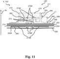
- the proximal part(s) may have lost contact to the respective connection part, e.g. if the material between the coupling part and the electrodes, e.g. due to viscous flow of material, has become thinner over time.
- the monitor interface such as the coupling part of the monitor interface, may be configured for connecting the base plate and/or the sensor assembly part to the device, such that, upon connection of the device to the base plate and/or the sensor assembly part, the connection part(s) of the one or more electrodes is forced towards the proximal part(s) of the one or more terminal elements, such as to reengage contact between the one or more terminal elements and respective electrodes.
- a first axial distance measured between the proximal facing edge of the coupling part and a contact surface on a distal side of the top layer may be configured such that, upon connecting the sensor assembly part to a device, the device abuts the contact surface and displaces the first connection part into contact with the first terminal element.
- the proximal facing edge of the coupling part may be configured for engagement with a distal facing edge of the device, e.g. in connecting the base plate and/or the sensor assembly part to the device.
- An axial distance along the axial direction between the proximal facing edge of the coupling part and a contact surface on the distal side of the top layer may be a first axial distance.
- the contact surface may overlap the proximal part of the first terminal element and the first connection part.
- the contact surface, the proximal part of the first terminal element and the first connection part may have at least one point in common in the base plate plane.
- the contact surface may be configured to abut a proximal facing side of the device, e.g. upon connecting the base plate and/or the sensor assembly part to the device.
- the first axial distance may be less than a second axial distance.
- the first axial distance may be between 0.01-1 mm less than the second axial distance, such as between 0.05 - 0.5 mm, such as between 0.1-0.3 mm.
- the second axial distance may be between the distal facing edge of the device and the proximal facing side of the device.
- the first axial distance may be less than the second axial distance, such that upon connecting the base plate and/or the sensor assembly part to the device the proximal facing side of the device contacts the contact surface, e.g. to apply pressure on the contact surface, to force the first connection parts to contact the first terminal element.
- a device such as a monitor device, such as a monitor device as disclosed above, an accessory device, a docking station or similar.
- the device may be configured for connecting to a base plate of an ostomy device or for connecting to a sensor assembly part for the base plate.
- the base plate defines a base plate plane and an axial direction being perpendicular to the base plate plane.
- the device may comprise a device housing, such as a monitor device housing.
- the device may comprise electronic circuitry.
- the electronic circuitry may include a processor and/or memory.
- the device may comprise an appliance interface.
- the appliance interface may be configured for connecting the device to the base plate and/or the sensor assembly part.
- the appliance interface may comprise one or more terminals including a first terminal for forming electrical connection with a first terminal of the base plate and/or the sensor assembly part.
- the one or more terminals may include a second terminal, a third terminal, a fourth terminal, a fifth terminal, a sixth terminal and/or a seventh terminal for forming electrical connection with respective terminals of the base plate and/or the sensor assembly part.
- the appliance interface may comprise a device coupling part, such as a monitor coupling part as disclosed above.
- the device coupling part may comprise a distal facing edge.
- the distal facing edge may be configured for engagement with a proximal facing edge of the base plate and/or the sensor assembly part, e.g. in connecting the base plate and/or the sensor assembly part to the device.
- the appliance interface such as the device coupling part of the appliance interface, may be configured for connecting the device to the base plate and/or the sensor assembly part, such that, upon connection of the device to the base plate and/or the sensor assembly part, connection part(s) of the base plate and/or the sensor assembly part is forced towards proximal part(s) of one or more terminal elements, such as to reengage contact between the one or more terminal elements and respective connection parts.
- An axial distance along the axial direction between the distal facing edge of the device coupling part and a proximal facing side of the device may be a second axial distance.
- the proximal facing side of the device may be configured to abut a contact surface of the base plate and/or the sensor assembly part, e.g. upon connecting the base plate and/or the sensor assembly part to the device.
- the second axial distance may be more than a first axial distance.
- the second axial distance may be between 0.01-1 mm more than the first axial distance, such as between 0.05 - 0.5 mm, such as between 0.1-0.3 mm.
- the first axial distance may be between the proximal facing edge of the base plate and/or the sensor assembly part and the contact surface of the base plate and/or the sensor assembly part.
- the second axial distance may be more than the first axial distance, e.g. such that upon connecting the base plate and/or the sensor assembly part to the device the proximal facing side of the device contacts the contact surface of the base plate and/or the sensor assembly part, e.g. to apply pressure on the contact surface of the base plate and/or the sensor assembly part.
- the ostomy system comprises a base plate, such as the base plate as disclosed above, and/or a sensor assembly part for the base plate, such as a sensor assembly part as disclosed above.
- the ostomy system comprises a device, such as a monitor device, an accessory device, a docking station or similar, configured to connect to the base plate and/or the sensor assembly part, such as the device as disclosed above.
- the base plate defines a base plate plane and an axial direction being perpendicular to the base plate plane.
- the device may comprise a device housing, such as a monitor device housing.
- the device may comprise electronic circuitry.
- the electronic circuitry may include a processor and/or memory.
- the device may comprise an appliance interface.
- the appliance interface may comprise one or more terminals including a first terminal for forming electrical connection with a first terminal of the base plate and/or the sensor assembly part.
- the one or more terminals may include a second terminal, a third terminal, a fourth terminal, a fifth terminal, a sixth terminal and/or a seventh terminal for forming electrical connection with respective terminals of the base plate and/or the sensor assembly part.
- the appliance interface may comprise a device coupling part comprising a distal facing edge.
- the base plate and/or the sensor assembly part may comprise a top layer, such as the top layer as disclosed above.
- the top layer may have a distal side and a proximal side. The distal side of the top layer may be exposed.
- the base plate and/or the sensor assembly part may comprise an electrode assembly, such as the electrode assembly as disclosed above.
- the electrode assembly may have a distal side and a proximal side.
- the electrode assembly may comprise one or more electrodes including a first electrode and optionally a second electrode, a third electrode, a fourth electrode, a fifth electrode, a sixth electrode and/or a seventh electrode.
- the first electrode may comprise a first connection part.
- the first electrode may be provided, such as formed, on a proximal side of the electrode assembly.
- the electrode assembly may comprise a support layer.
- the first electrode may be provided, such as formed, on a proximal side of the support layer.
- the second electrode, the third electrode, the fourth electrode, the fifth electrode, the sixth electrode and/or the seventh electrode may comprise respective connection parts.
- the second electrode, the third electrode, the fourth electrode, the fifth electrode, the sixth electrode and/or the seventh electrode may be provided, such as formed, on the proximal side of the electrode assembly, such as on the proximal side of the support layer.
- the base plate and/or the sensor assembly part may comprise a monitor interface, such as the monitor interface as disclosed above.
- the monitor interface may be configured for connecting the base plate and/or the sensor assembly part to the device.
- the monitor interface may comprise a coupling part.
- the coupling part may comprise a proximal facing edge.
- the distal side of the electrode assembly may be facing the coupling part.
- the distal side of the top layer may be facing the coupling part.
- the coupling part may be bonded to the distal side of the top layer.
- the monitor interface may comprise one or more terminal elements.
- the one or more terminal elements may include a first terminal element forming a first terminal of the base plate and/or the sensor assembly part.
- the one or more terminal elements may include a second terminal element forming a second terminal of the base plate and/or the sensor assembly part.
- the one or more terminal elements may include a third terminal element, a fourth terminal element, a fifth terminal element, a sixth terminal element and/or a seventh terminal element.
- the third terminal element, the fourth terminal element, the fifth terminal element, the sixth terminal element and/or the seventh terminal element may form respective terminals of the base plate and/or the sensor assembly part.
- a distal part of the first terminal element and/or the second terminal element and/or the third terminal element and/or the fourth terminal element and/or the fifth terminal element and/or the sixth terminal element and/or the seventh terminal element may be secured to the coupling part.
- a proximal part of the first terminal element may be in a position to contact the first connection part.
- a proximal part of the second terminal element and/or the third terminal element and/or the fourth terminal element and/or the fifth terminal element and/or the sixth terminal element and/or the seventh terminal element may be in a position to contact respective connection parts.
- the proximal part(s) may have lost contact to the respective connection part, e.g. if the material between the coupling part and the electrodes, e.g. due to viscous flow of material, has become thinner over time.
- the proximal facing edge of the base plate and/or the sensor assembly part may be configured for engagement with the distal facing edge of the device, e.g. in connecting the base plate and/or the sensor assembly part to the device.
- An axial distance along the axial direction between the proximal facing edge of the coupling part and a contact surface on the distal side of the top layer may be a first axial distance.
- the contact surface may overlap the proximal part of the first terminal element and the first connection part.
- the contact surface, the proximal part of the first terminal element and the first connection part may have at least one point in common in the base plate plane.
- the contact surface may be configured to abut a proximal facing side of the device, e.g. upon connecting the base plate and/or the sensor assembly part to the device.
- An axial distance along the axial direction between the distal facing edge of the device coupling part and a proximal facing side of the device may be a second axial distance.
- the proximal facing side of the device may be configured to abut a contact surface of the base plate and/or the sensor assembly part, e.g. upon connecting the base plate and/or the sensor assembly part to the device.
- the first axial distance may be less than the second axial distance.
- the first axial distance may be between 0.01-1 mm less than the second axial distance, such as between 0.05 - 0.5 mm, such as between 0.1-0.3 mm.
- the second axial distance may be between the distal facing edge of the device and the proximal facing side of the device.
- the first axial distance may be less than the second axial distance, such that upon connecting the base plate and/or the sensor assembly part to the device the proximal facing side of the device contacts the contact surface, e.g. to apply pressure on the contact surface, to force the first connection parts to contact the first terminal element.
- the proximal part(s) may have lost contact to the respective connection part(s), e.g. if the material between the coupling part and the electrodes, e.g. due to viscous flow of material, has become thinner over time, it may be necessary to provide for reengagement of the electrical connection between the proximal part(s) and the connection part(s). This may be achieved by dimensioning the device coupling part of the device and the coupling part of the monitor interface such that, upon connection of the device and the base plate and/or the sensor assembly part, pressure is applied to the contact parts, such that the contact parts and the proximal parts of the terminal elements are pressed together to provide for electrical connection between the two.
- first axial distance and the second axial distance may be measured at cooperating positions configured to be aligned when the device and the base plate and/or the sensor assembly part is completely connected, i.e. when the device is in coupled position with respect to the base plate and/or the sensor assembly part.
- the first axial distance may be measured from a first point of the proximal facing edge of the coupling part and the second axial distance may be measured from a second point of the distal facing edge of the device, wherein the first point and the second point are aligned and/or abutting when the device is completely connected to the base plate and/or the sensor assembly part.
- the coupling part may be attached to the top layer.
- the coupling part may be positioned on the distal side of the top layer and optionally the coupling part may be bonded, such as glued, soldered, or welded, to the top layer.
- a contact surface of the base plate and/or the sensor assembly part may be configured to abut a proximal facing side of the device, e.g. upon connecting the base plate and/or the sensor assembly part to the device.
- the contact surface may be formed by the top layer.
- the contact surface may be a part of the top layer.
- the contact surface may be a part of the coupling part, e.g. the coupling part, such as a distal surface of the coupling part, may form the contact surface.
- the coupling part may comprise a coupling flange.
- the coupling flange, such as a distal surface of the coupling flange may form the contact surface.
- the coupling flange may extend in the base plate plane.
- the coupling flange may be parallel to the top layer.
- the coupling flange may extend from a rim of the coupling part (explained in more detail below), such as radially extend from the rim of the coupling part.
- the coupling flange may be bonded to the top layer, such as glued, soldered, or welded, to the top layer.
- the coupling part and/or the contact surface may be made of plastic.
- the coupling part and/or the contact surface may be made of polyolefins, such as polyethylene, polypropylene, or similar.
- the coupling part and/or the contact surface may be made of polyethylene high-density.
- the coupling part and/or the contact surface may be made of acrylonitrile butadiene styrene.
- the coupling part and/or the contact surface may be made of polyphenylene oxide and/or polyethylene terephthalat and/or polybutylene terephthalate and/or polycarbonate and/or polyoxymethylene.
- the contact surface may comprise a protrusion, e.g. extending in the axial direction.
- the proximal facing side of the device may comprise a protrusion, e.g. extending along the axial direction.
- the protrusion(s) may provide for a reduction of the contact area between the contact surface and the proximal facing side of the device when the base plate and/or the sensor assembly part and the device are connected.
- the protrusion(s) may provide for ease of connection, since the frictional force may be reduced.
- the protrusion(s) may be provided to establish the difference of distances between the first axial distance and the second axial distance.
- the coupling part may comprise a rim.
- the rim may extend in the axial direction.
- the rim may comprise the proximal facing edge.
- the rim may comprise a groove extending substantially parallel to the base plate plane.
- the groove may form the proximal facing edge.
- the rim may comprise a protrusion extending parallel to the base plate plane. The protrusion may form the proximal facing edge.
- the base plate and/or the sensor assembly part may comprise a first adhesive layer, such as the first adhesive layer as disclosed above.
- the first adhesive layer may have a distal side facing the proximal side of the electrode assembly.
- the proximal part of the first terminal element, and optionally any other terminal element, may be located between the first adhesive layer and the electrode assembly.
- the base plate and/or the sensor assembly part may comprise a second adhesive layer, such as the second adhesive layer as disclosed above.
- the second adhesive layer may have a distal side facing the proximal side of the top layer.
- the second adhesive layer may have a proximal side facing the distal side of the electrode assembly.
- the base plate and/or the sensor assembly part may comprise one or more terminal elements.
- the one or more terminal elements may extend through the electrode assembly and the top layer and optionally the second adhesive layer.
- a distal part of each of the one or more terminal elements may extend into a terminal interface region, e.g. defined by the coupling part.
- the terminal interface region may be a region wherein terminals, e.g. of the base plate and/or sensor assembly part, may connect, such as mechanically and/or electrically connect, with respective terminals of a monitor device.
- a proximal part of each of the one or more terminal elements may contact respective connection parts of the one or more electrodes.
- the terminal elements extending through the electrode assembly and optionally other layers may provide for a connection on the distal side of the base plate and/or the sensor assembly part allowing electrical connection to the one or more electrodes being provided on the proximal side of the electrode assembly.
- the terminal elements may comprise one or more bends, such as a proximal terminal element bend and/or a distal terminal element bend.
- the proximal terminal element bend may provide that the proximal part of the terminal elements is in a position to contact respective connection parts.
- the distal terminal element bend may provide securing the distal part of the first terminal element to the coupling part, e.g. in that the distal part of each of the one or more terminal elements contact a surface, such as a distal surface, of the coupling part.
- a terminal element bend such as the proximal terminal element bend and/or the distal terminal element bend may form an angle, e.g. between 60-130 degrees, such as between 70-115 degrees, such as between 80-100 degrees.
- the angle of a terminal element bend may be defined relative to a straight terminal element, e.g. no bend has a 0 degrees angle and a U-shaped bend has a 180 degrees angle.
- the device may comprise a proximal facing side.
- the proximal facing side of the device may be configured to abut a contact surface of the base plate and/or the sensor assembly part, e.g. upon connecting the base plate and/or the sensor assembly part to the device.
- the device housing such as a proximal facing side of the device housing, may form the proximal facing side of the device.
- the device coupling part may comprise a device rim.
- the device rim may extend along the axial direction.
- the device rim may comprise the distal facing edge.
- the device rim may comprise a groove, e.g. extending substantially parallel to the base plate plane.
- the groove may form the distal facing edge.
- the device rim may comprise a protrusion, e.g. extending substantially parallel to the base plate plane. The protrusion may form the distal facing edge.
- Fig. 1 illustrates an exemplary ostomy system.
- the ostomy system 1 comprises an ostomy appliance 2 including a base plate 4.
- the base plate 4 is adapted to support an ostomy pouch (not shown).
- the ostomy system 1 comprises a monitor device 6 and an accessory device 8 (mobile telephone).
- the monitor device 6 is connectable to the base plate 4 via respective first connectors of the monitor device 6 and base plate 4.
- the monitor device 6 is configured for wireless communication with the accessory device 8.
- the accessory device 8 is configured to communicate with a server device 10 of the ostomy system 1, e.g. via network 12.
- the server device 10 may be operated and/or controlled by the ostomy appliance manufacturer and/or a service centre.
- Ostomy data or parameter data based on the ostomy data are obtained from electrodes/sensors of the ostomy appliance 2 with the monitor device 6.
- the monitor device 6 processes the ostomy data and/or parameter data based on the ostomy data to determine monitor data that are transmitted to the accessory device 8.
- the accessory device 8 is a mobile phone, however the accessory device 8 may be embodied as another handheld device, such as a tablet device, or a wearable, such as a watch or other wrist-worn electronic device. Accordingly, the monitor device 6 is configured to determine and transmit monitor data to the accessory device 8.
- the base plate 4 comprises a coupling member 14 in the form of a coupling ring 16 for coupling an ostomy pouch (not shown) to the base plate (two-part ostomy appliance).
- the base plate has a stoma-receiving opening 18 with a stoma center point. The size and/or shape of the stomal opening 18 is typically adjusted by the user or nurse before application of the ostomy appliance to accommodate the user's stoma.
- the ostomy system 1 optionally comprises a docking station 20 forming an accessory device of the ostomy system 1.
- the docking station 20 comprises a docking monitor interface including a first connector 22 configured for electrically and/or mechanically connecting the monitor device 6 to the docking station 20.
- the docking monitor interface may be configured for wirelessly connecting the monitor device to the docking station.
- the docking station 20 comprises a user interface 24 for receiving user input and/or providing feedback to the user on the operational state of the docking station 20.
- the user interface 24 may comprise a touch-screen.
- the user interface 24 may comprise one or more physical buttons and/or one or more visual indicators, such as light emitting diodes,
- Fig. 2 is a schematic block diagram of an exemplary monitor device.
- the monitor device 6 comprises a monitor device housing 100, a processor 101 and one or more interfaces, the one or more interfaces including a first interface 102 (appliance interface) and a second interface 104 (accessory interface).
- the monitor device 6 comprises a memory 106 for storing ostomy data and/or parameter data based on the ostomy data.
- the memory 106 is connected to the processor 101 and/or the first interface 102.
- the first interface 102 is configured as an appliance interface for electrically and/or mechanically connecting the monitor device 6 to the ostomy appliance, e.g. ostomy appliance 2.
- the first interface 102 comprises a plurality of terminals for forming electrical connections with respective terminals of the ostomy appliance 2 (base plate 4).
- the first interface 102 comprises a ground terminal 108, a first terminal 110, a second terminal 112 and a third terminal 114.
- the first interface 102 optionally comprises a fourth terminal 116 and a fifth terminal 118.
- the first interface 102 of the monitor device 6 comprises a coupling part 120 for forming a mechanical connection, such as a releasable coupling between the monitor device and the base plate.
- the coupling part 120 and the terminals 108, 110, 112, 114, 116, and 118 of the first interface 102 form (at least part of) a first connector of the monitor device 6.
- the monitor device 6 comprises a power unit 121 for powering the monitor device and active components thereof, i.e. the power unit 121 is connected to the processor 101, the first interface 102, the second interface 104, and memory 106.
- the power unit comprises a battery and charging circuitry.
- the charging circuitry is connected to the battery and terminals of the first interface 102 for charging the battery via terminals of the first interface, e.g. terminals of the first connector.
- the second interface 104 of monitor device is configured as an accessory interface for connecting the monitor device 6 to one or more accessory devices such as accessory device 8.
- the second interface 104 comprises an antenna 122 and a wireless transceiver 124 configured for wireless communication with accessory device(s).
- the second interface 104 comprises a loudspeaker 126 and/or a haptic feedback element 128 for provision of respective audio signal and/or haptic feedback to the user.
- the monitor device 6 comprises a sensor unit 140 connected to the processor 101.
- the sensor unit 140 comprises a temperature sensor for feeding temperature data to the processor and a G-sensor or accelerometer for feeding acceleration data to the processor 101.
- the processor 101 is configured to apply a processing scheme
- the first interface 102 is configured for collecting ostomy data from the base plate coupled to the first interface, the ostomy data comprising first ostomy data from a first electrode pair of the base plate, second ostomy data from a second electrode pair of the base plate, and third ostomy data from a third electrode pair of the base plate.
- the ostomy data may be stored in the memory 106 and/or processed in the processor 101 in order to obtain parameter data.
- the parameter data may be stored in the memory 106.
- the processor 101 is configured to apply a processing scheme, wherein to apply a processing scheme comprises obtain first parameter data based on the first ostomy data; obtain second parameter data based on the second ostomy data; obtain third parameter data based on the third ostomy data.
- the processor 101 is configured to obtain first, second and third parameter data based on respective first, second and third ostomy data.
- To apply a processing scheme comprises to determine an operating state of the base plate of the ostomy appliance based on one or more, e.g. all, of the first parameter data, the second parameter data and the third parameter data, wherein the operating state is indicative of a degree of radial erosion of the base plate and/or acute leakage risk for the ostomy appliance.
- the monitor device 6 is configured to, in accordance with a determination that the operating state is a first operating state, transmit a first monitor signal comprising monitor data indicative of the first operating state of the base plate via the second interface; and in accordance with a determination that the operating state is a second operating state, transmit a second monitor signal comprising monitor data indicative of the second operating state of the base plate via the second interface.
- Fig. 3 illustrates an exploded view of an exemplary base plate of an ostomy appliance.
- the base plate 4 comprises a first adhesive layer 200.
- a proximal surface of the first adhesive layer 200 adheres to the user's skin in the peristomal area and/or to additional seals, such as sealing paste, sealing tape and/or sealing ring.
- the base plate 4 optionally comprises a second adhesive layer 202, also denoted rim adhesive layer.
- the base plate 4 comprises a plurality of electrodes arranged in an electrode assembly 204.
- the electrode assembly 204 is arranged between the first adhesive layer 200 and the second adhesive layer 202.
- the electrode assembly 204 comprises a support layer with electrodes formed on a proximal surface of the support layer.
- the base plate 4 comprises a release liner 206 that is peeled off by the user prior to applying the base plate 4 on the skin.
- the base plate 4 comprises a top layer 208 and a coupling ring 209 for coupling an ostomy pouch to the base plate 4.
- the top layer 208 is a protective layer protecting the second adhesive layer 202 from external strains and stress during use.
- the base plate 4 comprises a monitor interface.
- the monitor interface is configured for electrically and/or mechanically connecting the ostomy appliance (base plate 4) to the monitor device.
- the monitor interface of the base plate comprises a coupling part 210 for forming a mechanical connection, such as a releasable coupling between the monitor device and the base plate.
- the coupling part 210 is configured to engage with a coupling part of the monitor device for releasably coupling the monitor device to the base plate 4.
- the monitor interface of the base plate 4 comprises a plurality of terminal elements respectively forming a plurality of terminals 212 for forming electrical connections with respective terminals of the monitor device.
- the coupling part 210 and the terminals 212 form a first connector 211 of the base plate 4.
- the base plate 4 comprises a first intermediate element 213 on the proximal side of the electrode assembly.
- the first intermediate element 213 is arranged between the terminal elements forming terminals 212 and the first adhesive layer (not shown).
- the first intermediate element 213 covers the terminal elements forming terminals 212 of the base plate 4 when seen in the axial direction and protects the first adhesive layer from mechanical stress from the terminal elements of the base plate.
- a sensor assembly part 700 may be provided, e.g. comprising the electrode assembly 204, the first connector 211, the first intermediate element 213, the first adhesive layer 200 and the release liner 206. Additionally, the sensor assembly part 700 may also comprise the second adhesive layer 202 and/or the top layer 208.
- the user may provide a hole in layers of the base plate whereto the sensor assembly part 700 is to be applied, to allow for the first connector 211 of the sensor assembly part 700 to protrude through layers of the base plate whereto the sensor assembly part 700 is applied.
- the sensor assembly part 700 may be applied to the base plate such that the first connector 211 is positioned outside the periphery of the base plate.
- Fig. 4 illustrates an exploded view of an exemplary electrode assembly 204 of a base plate and/or a sensor assembly part.
- the electrode assembly 204 has a distal side 204A and a proximal side 204B.
- the electrode assembly comprises a support layer 214 with proximal surface 214B and electrodes 216 including a ground electrode, a first electrode, a second electrode, a third electrode, a fourth electrode, and a fifth electrode, wherein each electrode has a respective connection part 217 for connecting the electrodes 216 to respective terminal elements of the monitor interface.
- the electrodes 216 are provided, such as formed, on a proximal side 214B of the support layer 214, e.g.
- electrode assembly 204 comprises a masking element 218 with proximal surface 218B and configured to insulate electrode parts of electrodes 216 from the first adhesive layer of the base plate and/or the sensor assembly part.
- the masking element 218 covers or overlap with parts of the electrodes 216 when seen in the axial direction.
- Fig. 5 is a proximal view of proximal surfaces of base plate parts of the base plate and/or a sensor assembly part without the first adhesive layer and the release liner.
- the base plate 4 and/or the sensor assembly part 700 comprises a first intermediate element 213 on the proximal side of the electrode assembly, i.e. between the electrode assembly 204 and the first adhesive layer (not shown).
- the first intermediate element 213 covers the terminal elements of the base plate 4 when seen in the axial direction and protects the first adhesive layer from mechanical stress from the terminal elements of the base plate and/or the sensor assembly part.
- Fig. 6 is a distal view of an exemplary electrode configuration 220 of electrodes 216 of the electrode assembly 204.
- the electrode assembly 204 such as the electrode configuration 220 of the electrode assembly 204 comprises a ground electrode 222, a first electrode 224, a second electrode 226, a third electrode 228, a fourth electrode 230, and a fifth electrode 232.
- the ground electrode 222 comprises a ground connection part 222A and the first electrode 224 comprises a first connection part 224A.
- the second electrode 226 comprises a second connection part 226A and the third electrode 228 comprises a third connection part 228A.
- the fourth electrode 230 comprises a fourth connection part 230A and the fifth electrode 232 comprise a fifth connection part 232A.
- the fourth electrode 230 comprises fourth sensing parts 230B.
- the fifth electrode 232 comprises fifth sensing parts 232B.
- the ground electrode 222 comprises a first electrode part 234 for forming a ground for the first electrode 224.
- the ground electrode 222 comprises a second electrode part 236 for forming a ground for the second electrode 226.
- the ground electrode 222 comprises a third electrode part 238 for forming a ground for the third electrode 228.
- the ground electrode 222 comprises a fourth electrode part 240 for forming a ground for the fourth electrode 230 and the fifth electrode 232.
- the fourth electrode part 240 of the ground electrode 222 comprises ground sensing parts 222B
- Fig. 7 is a distal view of an exemplary masking element.
- the masking element 218 optionally has a plurality of terminal openings including six terminal openings.
- the plurality of terminal openings comprises a ground terminal opening 242, a first terminal opening 244, a second terminal opening 246, a third terminal opening 248, a fourth terminal opening 250, and a fifth terminal opening 252.
- the terminal openings 242, 244, 246, 248, 250, 252 of the masking element 218 are configured to overlap and/or be aligned with respective connection parts 222A, 224A, 226A, 228A, 230A, 232A of the electrodes of the electrode assembly.
- the masking element 218 has a plurality of sensor point openings.
- the sensor point openings comprise primary sensor point openings shown within dotted line 254, each primary sensor point opening configured to overlap a part of the ground electrode 222 and/or a part of the fourth electrode 230.
- the primary sensor point openings 254 comprise, in the illustrated exemplary masking element, five primary first sensor point openings 254A each configured to overlap a part of the ground electrode 222.
- the primary sensor point openings 254 comprise, in the illustrated exemplary masking element, four primary second sensor point openings 254B each configured to overlap a part of the fourth electrode 230.
- the sensor point openings comprise secondary sensor point openings shown within dotted line 256, each second sensor point opening configured to overlap a part of the fourth electrode 230 and/or a part of the fifth electrode 232.
- the secondary sensor point openings 256 comprise, in the illustrated exemplary masking element, five secondary first sensor point openings 256A each configured to overlap a part of the fifth electrode 232.
- the secondary sensor point openings 256 comprise, in the illustrated exemplary masking element, four secondary second sensor point openings 256B each configured to overlap a part of the fourth electrode 230.
- the sensor point openings comprise tertiary sensor point openings shown within dotted line 258, each tertiary sensor opening configured to overlap a part of the fifth electrode 232 and/or a part of the ground electrode 222.
- the tertiary sensor point openings 258 comprise, in the illustrated exemplary masking element, five tertiary first sensor point openings 258A each configured to overlap a part of the fifth electrode 232.
- the tertiary sensor point openings 258 comprise, in the illustrated exemplary masking element, four tertiary second sensor point openings 258B each configured to overlap a part of the ground electrode 222.
- Fig. 8 is a distal view of an exemplary first adhesive layer.
- the first adhesive layer 200 has a plurality of sensor point openings.
- the sensor point openings of the first adhesive layer comprise primary sensor point openings shown within dotted line 260, each primary sensor point opening configured to overlap a part of the ground electrode 222 and/or a part of the fourth electrode 230 of the electrode assembly.
- the primary sensor point openings 260 comprise, in the illustrated exemplary first adhesive layer, five primary first sensor point openings 260A each configured to overlap a part of the ground electrode 222.
- the primary sensor point openings 260 comprise, in the illustrated exemplary first adhesive layer, four primary second sensor point openings 260B each configured to overlap a part of the fourth electrode 230.
- the sensor point openings of the first adhesive layer comprise secondary sensor point openings shown within dotted line 262, each second sensor point opening configured to overlap a part of the fourth electrode 230 and/or a part of the fifth electrode 232 of the electrode assembly.
- the secondary sensor point openings 262 comprise, in the illustrated exemplary first adhesive layer, five secondary first sensor point openings 262A each configured to overlap a part of the fifth electrode 232.
- the secondary sensor point openings 262 comprise, in the illustrated exemplary first adhesive layer, four secondary second sensor point openings 262B each configured to overlap a part of the fourth electrode 230.
- the sensor point openings of the first adhesive layer comprise tertiary sensor point openings shown within dotted line 264, each tertiary sensor opening configured to overlap a part of the fifth electrode 232 and/or a part of the ground electrode 222 of the electrode assembly.
- the tertiary sensor point openings 264 comprise, in the illustrated exemplary first adhesive layer, five tertiary first sensor point openings 264A each configured to overlap a part of the fifth electrode 232.
- the tertiary sensor point openings 264 comprise, in the illustrated exemplary first adhesive layer, four tertiary second sensor point openings 264B each configured to overlap a part of the ground electrode 222.
- Fig. 9 is a proximal view of the first adhesive layer of Fig. 8 .
- Fig. 10 is a more detailed distal view of a part of the base plate 4 and/or the sensor assembly part 700.
- the base plate 4 and/or the sensor assembly part 700 comprises a monitor interface 207.
- the monitor interface 207 of the base plate comprises the first connector 211.
- the first connector 211 comprises coupling part 210 configured to releasably couple the monitor device to the base plate and thus forming a releasable coupling.
- the first connector 211 and/or the monitor interface 207 comprises a plurality of terminals formed by respective terminal elements for forming respective electrical connections with respective terminals of the monitor device 207.
- the plurality of terminals of the first connector 211 and/or monitor interface 207 comprises a ground terminal element 282 forming a ground terminal 282A, a first terminal element 284 forming a first terminal 284, a second terminal element 286 forming a second terminal 286A, and a third terminal element 288 forming a third terminal 288A.
- the monitor interface optionally comprises a fourth terminal element 290 forming a fourth terminal 290A and/or a fifth terminal element 292 forming a fifth terminal 290.
- the terminal elements 282, 284, 286, 288, 290, 292 contact respective connection parts 222A, 224A, 226A, 228A, 230a, 232A of electrodes 222, 224, 226, 228, 230, 232.
- Fig. 11 schematically illustrates a section of a base plate 4 and/or a sensor assembly part 700 comprising a monitor interface 207.
- the monitor interface 207 comprises a first connector 211.
- the monitor interface 207 and/or the first connector 211 comprises a coupling part 210.
- the coupling part 210 defines a terminal interface region 270.
- the coupling part 210 comprises proximal facing edge 294.
- the base plate 4 and/or the sensor assembly part 700 comprises an electrode assembly 204 having a distal side and a proximal side.
- the distal side of the electrode assembly 204 is facing the coupling part 210.
- the electrode assembly 204 comprises a plurality of electrodes including a first electrode.
- the first electrode comprises a first connection part 224A.
- the electrode assembly 204 may comprise a support layer 214, e.g. as disclosed in relation to previous figures.
- the electrodes are provided on a proximal side of the support layer 214. Alternatively, the electrodes may be provided on a distal side of the support layer 214.
- the base plate 4 and/or the sensor assembly part 700 comprises a top layer 208.
- the top layer 208 has a distal side facing the coupling part 210 and a proximal side facing the distal side of the electrode assembly 204.
- the base plate 4 and/or the sensor assembly part 700 comprises an optional second adhesive layer 202.
- the second adhesive layer 202 has a distal side facing the proximal side of the top layer 208.
- the second adhesive layer 202 has a proximal side facing the distal side of the electrode assembly 204.
- the monitor interface 207 comprising a plurality of terminal elements 272 including a first terminal element 284.
- the first terminal element 284 forms a first terminal of the base plate 4 and/or the sensor assembly part 700, such as a first terminal of the monitor interface 207 of the base plate 4 and/or the sensor assembly part 700.
- a distal part 274A of the first terminal element 284 is secured to the coupling part 210.
- a proximal part 274B of the first terminal element 284 is in a position to contact the first connection part 224A.
- the proximal parts 274B may have lost contact to the respective connection parts, e.g. if the material between the coupling part and the electrodes, e.g. due to viscous flow of material, has become thinner over time.
- the base plate 4 and/or the sensor assembly part 700 comprises a first adhesive layer 200.
- the first adhesive layer 200 has a distal side facing the proximal side of the electrode assembly 204.
- the proximal part 274B of the terminal elements 272, including the first terminal element 284, are located between the first adhesive layer 200 and the electrode assembly 204.
- the terminal elements 272 extends through the electrode assembly 204, the second adhesive layer 202, and the top layer 208.
- Each of the terminal elements 272 have a distal part 274A extending into the terminal interface region 270 and a proximal part 274B extending to the proximal side of the electrode assembly 204.
- the terminal elements 272 comprises terminal element bends 276A; 276B between the proximal part 274B and the distal part 274A.
- each of the terminal elements 272 e.g. including the first terminal element 284, contact a distal surface of the coupling part 210, e.g. in order to secure the terminal elements 272 to the coupling part 210.
- the proximal facing edge 294 is configured for engagement with corresponding part of a device, such as a monitor device, an accessory device, a docking station or similar.
- a device such as a monitor device, an accessory device, a docking station or similar.
- the proximal facing edge 294 is configured for engagement with a distal facing edge of the device, such as a monitor device (see Fig. 12-13 ) when the base plate 4 and/or the sensor assembly part 700 is connected to the device, such as fully connected with the device.
- the coupling part 210 comprises a rim 293.
- the rim 293 extends in the axial direction Ax.
- the rim 293 comprises the proximal facing edge 294.
- the rim 293 comprises a protrusion extending substantially parallel to the base plate plane, and the lower part of the protrusion forms the proximal facing edge 294.
- the rim 293 could have comprised a groove extending substantially parallel to the base plate plane, and the upper part of the groove could in such case form the proximal facing edge 294.
- the base plate 4 and/or the sensor assembly part 700 comprises a contact surface 298, here shown as a coupling flange extending in the base plate plane from the rim 293.
- the contact surface 298 is on the distal side of the top layer.
- the contact surface 298 is configured to abut a side, such as a proximal facing side, of the device upon connecting the base plate 4 and/or the sensor assembly part 700 to the device.
- the contact surface is overlapping, e.g. in the base plate plane, the proximal part 274B of the terminal elements 272, such as the first terminal element 284, and the connection parts, such as the first connection part 224A.
- the contact surface 298, the proximal part 274B of the terminal elements 272 and the connection parts have at least one point in common in the base plate plane.
- the contact surface 298 comprises an optional protrusion 299.
- the protrusion 299 extends in the axial direction Ax.
- the protrusion 299 may reduce the area of contact between the contact surface 298 and the device.
- the protrusion 299 may provide for ease of connection, e.g. in a rotational connection between the device and the base plate and/or the sensor assembly part, since the frictional force may be reduced.
- An axial distance along the axial direction Ax between the proximal facing edge 294 of the coupling part 210 and the contact surface 298 is a first axial distance L1.
- the first axial distance L1 is less than a corresponding distance of the device, such as a second axial distance (e.g. L2 of Fig. 13 ) between the distal facing edge of the device (e.g. 131 of Fig. 13 ) and the proximal facing side of the device (e.g. 132 of Fig. 13 ).
- the first axial distance L1 being smaller than the corresponding distance of the device provides that upon connecting the base plate 4 and/or the sensor assembly part 700 to the device the proximal facing side of the device contacts the contact surface 298 to force the first connection part 224A to contact the first terminal element 284. Thereby electrical connection between the first connection part and the first terminal element 284 may be reestablished and/or reassured.
- Fig. 12 schematically illustrates an exemplary monitor device 6, such as the monitor device as described in relation to previous figures.
- Fig. 12 is shown from the proximal side of the monitor device 6.
- Fig. 13 schematically illustrates a cross sectional view of the monitor device 6, as indicated by the line A-A.
- the monitor device 6 is configured to connect to a base plate and/or a sensor assembly part of an ostomy device.
- the base plate defines a base plate plane BP and an axial direction Ax being perpendicular to the base plate plane BP.
- the base plate plane BP and the axial direction Ax are shown in Fig. 13 , and corresponds to, if the monitor device 6 is connected to the base plate and/or the sensor assembly part as applied to the base plate.
- the monitor device 6 comprises a monitor device housing 100.
- the monitor device 6 comprises electronic circuitry, such as a processor.
- the monitor device 6 comprises an appliance interface 102.
- the appliance interface 102 is configured for connecting the monitor device 6 to a base plate and/or the sensor assembly part, e.g. such as the base plate 4 and/or the sensor assembly part 700 as described in relation to Fig. 11 .
- the appliance interface 102 comprises a plurality of terminals including a first terminal 110.
- the terminals are configured for forming electrical connections with respective terminals of the base plate and/or the sensor assembly part.
- the first terminal is configured for forming an electrical connection with a first terminal of the base plate and/or the sensor assembly part.
- the appliance interface 102 comprises a monitor coupling part 120.
- the monitor coupling part 120 comprises a distal facing edge 131.
- the distal facing edge 131 is configured for engagement with a corresponding part of the base plate and/or the sensor assembly part, such as a proximal facing edge of the base plate and/or the sensor assembly part (see Fig. 11 ) when the base plate and/or the sensor assembly part is connected to the monitor device 6.
- the monitor coupling part 120 comprises a monitor rim 130.
- the monitor rim 130 extends along the axial direction Ax.
- the monitor rim 130 comprises the distal facing edge 131.
- the monitor rim 130 comprises a protrusion extending substantially parallel to the base plate plane, and the lower part of the protrusion forms the distal facing edge 131.
- the monitor rim 130 could have comprised a groove extending substantially parallel to the base plate plane, and the upper part of the groove would form the distal facing edge 131.
- the monitor device comprises a proximal facing side 132.
- the proximal facing side 132 may be formed by the monitor housing 100, as shown.
- the proximal facing side 132 is configured to abut a contact surface of the base plate and/or the sensor assembly part upon connecting the base plate and/or the sensor assembly part to the monitor device 6.
- the proximal facing side 132 comprises an optional protrusion 134.
- the protrusion 134 extends along the axial direction.
- the protrusion 134 may reduce the area of contact between the proximal facing side 132 and the base plate and/or the sensor assembly part.
- the protrusion 134 may provide for ease of connection, e.g. in a rotational connection between the monitor device and the base plate and/or the sensor assembly part, since the frictional force may be reduced.
- An axial distance along the axial direction Ax between the distal facing edge 131 of the monitor coupling part 120 and the proximal facing side 132 is a second axial distance L2.
- the second axial distance L2 is more than a corresponding distance of the base plate and/or the sensor assembly part, such as a first axial distance (e.g. L1 of Fig. 11 ) between the proximal facing edge of the base plate (e.g. 294 of Fig. 11 ) and the contact surface of the base plate and/or the sensor assembly part (e.g. 298 of Fig. 11 ).
- the second axial distance L2 being more than the corresponding distance of the base plate and/or the sensor assembly part provides that upon connecting the base plate and/or the sensor assembly part to the monitor device 6 the proximal facing side of the monitor device contacts the contact surface of the base plate and/or the sensor assembly part. Thereby electrical connection between connection parts and terminal elements may be reestablished and/or reassured.
- Fig. 14 schematically illustrates parts of an ostomy system 1, such as an ostomy system as described in relation to previous figures.
- the ostomy system 1 comprises a base plate 4 and/or a sensor assembly part 700, such as explained in relation to Fig. 11 , and a monitor device 6, such as explained in relation to Fig. 12 and 13 .
- the base plate 4 and/or the sensor assembly part 700 is connected to the monitor device 6.
- the proximal facing edge 294 is engaging with the distal facing edge 131 of the monitor device 6.
- the distance between the proximal facing edge 294 and the contact surface 298 of the base plate 4 and/or the sensor assembly part 700 is slightly less than the distance between the distal facing edge 131 and the proximal facing side 132 of the monitor device 6, pressure is provided on the contact surface 298 by the proximal facing side 132, and pressure is provided on the proximal facing edge 294 by the distal facing edge 131.
- the proximal facing side 132 of the monitor device 6 is abutting the contact surface 298 of the base plate 4 and/or the sensor assembly part 700, and the contact surface 298, the top layer 208, the second adhesive layer 202, and the electrode assembly 204 is forced in the direction towards the proximal part 274B of the terminal elements 272.
- the terminal elements 272 are secured to the coupling part 210.
- the pressure provided on the proximal facing edge 294 forces the terminal elements 272 in the axial direction.
- the proximal part 274B of the terminal elements 272 is forced to contact the connection parts of the electrode assembly, such as the first connection 224A.
- electrical contact between the terminal elements 272 and their respective connection parts is ensured.
- the terminals of the monitor device 6 may therefore be electrically connected to the electrodes of the electrode assembly 204.
- the first terminal 110 of the monitor device is electrically connected to a first electrode of the electrode assembly 204 via the first terminal element 284.
- the position of the first connector on the base plate and/or the sensor assembly part, the number of terminals and the position of the terminals in the coupling part may be adapted to the electrode configuration used in the electrode assembly of the base plate and/or the sensor assembly part.
Landscapes
- Health & Medical Sciences (AREA)
- Life Sciences & Earth Sciences (AREA)
- Engineering & Computer Science (AREA)
- Veterinary Medicine (AREA)
- Biomedical Technology (AREA)
- Heart & Thoracic Surgery (AREA)
- Animal Behavior & Ethology (AREA)
- General Health & Medical Sciences (AREA)
- Public Health (AREA)
- Orthopedic Medicine & Surgery (AREA)
- Vascular Medicine (AREA)
- Nursing (AREA)
- Epidemiology (AREA)
- Biophysics (AREA)
- Physics & Mathematics (AREA)
- Pathology (AREA)
- Medical Informatics (AREA)
- Molecular Biology (AREA)
- Surgery (AREA)
- Chemical & Material Sciences (AREA)
- Dispersion Chemistry (AREA)
- Transplantation (AREA)
- Computer Networks & Wireless Communication (AREA)
- Orthopedics, Nursing, And Contraception (AREA)
Claims (18)
- Plaque (4) de base pour un appareil (2) de stomie, la plaque (4) de base définissant un plan de plaque de base (BP), une direction axiale étant perpendiculaire au plan de plaque de base, la plaque de base comportant :- une couche supérieure (208) présentant un côté distal et un côté proximal ;- un ensemble (204) d'électrodes comportant une ou plusieurs électrodes (216) comprenant une première électrode (224), la première électrode comportant une première partie (224A) de connexion, un côté distal de l'ensemble d'électrodes faisant face au côté proximal de la couche supérieure (208) ;- une interface (207) de surveillance configurée pour connecter la plaque (4) de base à un dispositif (6), l'interface (207) de surveillance comportant une partie (210) de couplage comportant un bord (294) d'orientation proximale, le côté distal de l'ensemble (204) d'électrodes faisant face à la partie (210) de couplage, et l'interface (207) de surveillance comportant un ou plusieurs éléments (272) de bornes comprenant un premier élément (284) de borne formant une première borne de la plaque (4) de base, une partie distale (274a) du premier élément de borne étant fixée à la partie (210) de couplage et une partie proximale du premier élément (284) de borne se trouvant en position d'entrer en contact avec la première partie (224A) de connexion ; et- une première couche adhésive (200) dont un côté distal fait face au côté proximal de l'ensemble (204) d'électrodes, et la partie proximale (274B) de l'élément ou de chacun des éléments (272) de bornes étant située entre la première couche adhésive (200) et l'ensemble (204) d'électrodes, la première couche adhésive (200) comportant un ou plusieurs hydrocolloïdes solubles dans l'eau ou gonflant en présence d'eau,le bord (294) d'orientation proximale étant configuré pour interagir avec un bord (131) d'orientation distale du dispositif (6) lorsque la plaque (4) de base est liée au dispositif (6),et une distance axiale suivant la direction axiale Ax entre le bord (294) d'orientation proximale de la partie (210) de couplage et une surface (298) de contact sur le côté distal de la couche supérieure (208) étant une première distance axiale (L1), la surface (298) de contact chevauchant la partie proximale du premier élément (284) de borne et la première partie (224A) de connexion, et la surface (298) de contact étant configurée pour porter contre un côté (132) d'orientation proximale du dispositif (6) suite à la liaison de la plaque (4) de base avec le dispositif (6),la partie (210) de couplage étant configurée de telle façon que la première distance axiale (L1) soit inférieure à une seconde distance axiale (L2) entre le bord (131) d'orientation distale du dispositif (6) et le côté (132) d'orientation proximale du dispositif (6), de telle façon que suite à la liaison de la plaque (4) de base avec le dispositif, le côté (132) d'orientation proximale du dispositif entre en contact avec la surface (298) de contact pour forcer la première partie (224A) de connexion à entrer en contact avec le premier élément (284) de borne.
- Plaque de base selon la revendication 1 comportant une ouverture de stomie au moins partiellement formée par une ouverture de stomie de couche supérieure de la couche supérieure (208) et une ouverture de stomie de première couche adhésive de la première couche adhésive, l'ouverture de stomie de la plaque (4) de base étant configurée pour permettre le passage d'une sortie provenant d'une stomie d'un utilisateur.
- Plaque de base selon l'une quelconque des revendications précédentes, la partie (210) de couplage comportant une bride de couplage formant la surface (298) de contact, et la bride de couplage s'étendant dans le plan de plaque de base (BP).
- Plaque de base selon l'une quelconque des revendications précédentes, la bride de couplage qui forme la surface (298) de contact étant constituée de polyéthylène à haute densité.
- Plaque de base selon l'une quelconque des revendications précédentes, la surface (298) de contact comportant une protubérance (299) s'étendant dans la direction axiale.
- Plaque de base selon l'une quelconque des revendications précédentes, la partie (210) de couplage comportant un rebord (293) s'étendant dans la direction axiale, et le rebord comportant le bord (294) d'orientation proximale.
- Plaque de base selon la revendication 6, le rebord (293) comportant une rainure s'étendant sensiblement parallèlement au plan de plaque de base (BP), la rainure formant le bord d'orientation proximale.
- Plaque de base selon la revendication 6, le rebord (293) comportant une protubérance s'étendant sensiblement parallèlement au plan de plaque de base, la protubérance formant le bord d'orientation proximale.
- Plaque de base selon l'une quelconque des revendications précédentes, comportant une seconde couche adhésive (202) dont un côté distal fait face au côté proximal de la couche supérieure (208) et un côté proximal fait face au côté distal de l'ensemble (204) d'électrodes.
- Dispositif (6) destiné à être lié à une plaque (4) de base selon l'une quelconque des revendications précédentes, le dispositif comportant :- un boîtier (100) de dispositif ;- une circuiterie électronique ;- une interface (102) d'appareil configurée pour lier le dispositif (6) à une plaque (4) de base, l'interface (102) d'appareil comportant une ou plusieurs bornes comprenant une première borne (110) destinée à former une connexion électrique avec une première borne de la plaque de base, l'interface (102) d'appareil comportant une partie (120) de couplage de dispositif comportant un bord (131) d'orientation distale,le bord (131) d'orientation distale étant configuré pour interagir avec un bord (294) d'orientation proximale de la plaque (4) de base lorsque la plaque de base est liée au dispositif (6),et une distance axiale suivant la direction axiale Ax entre le bord (131) d'orientation distale de la partie (120) de couplage de dispositif et un côté (132) d'orientation proximale du dispositif étant une seconde distance axiale L2, le côté (132) d'orientation proximale du dispositif étant configuré pour porter contre une surface (298) de contact de la plaque (4) de base suite à la liaison de la plaque (4) de base avec le dispositif (6),la partie (120) de couplage de dispositif étant configurée de telle façon que la seconde distance axiale L2 soit supérieure à première distance axiale L1 entre le bord (294) d'orientation proximale de la plaque (4) de base et la surface (298) de contact de la plaque (4) de base, de telle façon que suite à la liaison de la plaque (4) de base avec le dispositif (6), le côté (132) d'orientation proximale du dispositif (6) entre en contact avec la surface (298) de contact de la plaque (4) de base.
- Dispositif (6) selon la revendication 10, la circuiterie électronique comprenant un processeur (101).
- Dispositif selon l'une quelconque des revendications 10 à 11, le boîtier (100) de dispositif formant le côté (132) d'orientation proximale du dispositif (6).
- Dispositif selon l'une quelconque des revendications 10 à 12, le côté (132) d'orientation proximale du dispositif (6) comportant une protubérance (134) s'étendant suivant la direction axiale.
- Dispositif selon l'une quelconque des revendications 10 à 13, la partie (120) de couplage de dispositif comportant un rebord (130) de dispositif s'étendant suivant la direction axiale, et le rebord de dispositif comprenant le bord (131) d'orientation distale.
- Dispositif selon la revendication 14, le rebord (130) de dispositif comportant une rainure s'étendant sensiblement parallèlement au plan de plaque de base, la rainure formant le bord (131) d'orientation distale.
- Dispositif selon la revendication 14, le rebord (130) de dispositif comportant une protubérance s'étendant sensiblement parallèlement au plan de plaque de base, la protubérance formant le bord (131) d'orientation distale.
- Dispositif selon l'une quelconque des revendications 10 à 16, le dispositif étant un dispositif de surveillance configuré pour transmettre des données de surveillance à un dispositif accessoire, tel qu'un téléphone.
- Système de stomie comportant une plaque (4) de base selon l'une quelconque des revendications 1 à 9 et un dispositif selon l'une quelconque des revendications 10 à 17.
Applications Claiming Priority (2)
| Application Number | Priority Date | Filing Date | Title |
|---|---|---|---|
| DKPA201770999 | 2017-12-22 | ||
| PCT/DK2018/050398 WO2019120442A1 (fr) | 2017-12-22 | 2018-12-20 | Partie d'ensemble capteur et plaque de base pour un appareil de stomie et dispositif de connexion à une plaque de base ou à une partie d'ensemble capteur |
Publications (2)
| Publication Number | Publication Date |
|---|---|
| EP3727237A1 EP3727237A1 (fr) | 2020-10-28 |
| EP3727237B1 true EP3727237B1 (fr) | 2024-08-21 |
Family
ID=66994416
Family Applications (1)
| Application Number | Title | Priority Date | Filing Date |
|---|---|---|---|
| EP18833833.9A Active EP3727237B1 (fr) | 2017-12-22 | 2018-12-20 | Plaque de base pour un appareil de stomie et dispositif de connexion à une plaque de base |
Country Status (3)
| Country | Link |
|---|---|
| US (2) | US11628084B2 (fr) |
| EP (1) | EP3727237B1 (fr) |
| WO (1) | WO2019120442A1 (fr) |
Families Citing this family (76)
| Publication number | Priority date | Publication date | Assignee | Title |
|---|---|---|---|---|
| EP2142149A1 (fr) | 2007-04-24 | 2010-01-13 | Bristol-Myers Squibb Company | Système de fermeture pour une poche vidangeable |
| CN102281840B (zh) | 2007-06-12 | 2016-05-11 | 康沃特克科技公司 | 造口术器具 |
| WO2010060115A1 (fr) | 2008-11-19 | 2010-05-27 | Convatec Technologies Inc. | Appareil à étui d'ostomie |
| JP5902084B2 (ja) | 2009-07-07 | 2016-04-13 | コンバテック・テクノロジーズ・インコーポレイテッドConvatec Technologies Inc | 両親媒性コポリマーを有する感圧シリコーン接着剤 |
| KR101925739B1 (ko) | 2009-09-11 | 2018-12-05 | 컨바텍 테크놀러지스 인크 | 제어 배설 조루 기구 및 조루 기구용 쉴드 |
| US10285847B2 (en) | 2011-09-29 | 2019-05-14 | Convatec Technologies Inc. | Ostomy pouch with filtering system |
| GB201115160D0 (en) | 2011-09-02 | 2011-10-19 | Trio Healthcare Ltd | Discharge solidifier and malodour control |
| US10531977B2 (en) | 2014-04-17 | 2020-01-14 | Coloplast A/S | Thermoresponsive skin barrier appliances |
| BR112016024816A2 (pt) | 2014-04-24 | 2017-08-15 | Convatec Technologies Inc | sistema de filtragem de bolsa de ostomia |
| EP4248921B1 (fr) | 2015-10-14 | 2026-05-13 | ConvaTec Technologies Inc. | Dispositif médical avec système d'ouverture |
| US11141100B2 (en) | 2015-12-23 | 2021-10-12 | Coloplast A/S | Moisture assessment system and method for wound care |
| LT3727240T (lt) | 2017-12-22 | 2022-03-10 | Coloplast A/S | Ostomijos sistemos papildomi įrenginiai ir susiję būdai veikimo būsenai perduoti |
| EP4032510B1 (fr) | 2017-12-22 | 2025-07-09 | Coloplast A/S | Plaque de base avec points de capteur sélectifs et méthode de fabrication |
| US11865029B2 (en) | 2017-12-22 | 2024-01-09 | Coloplast A/S | Monitor device of a medical system having a connector for coupling to both a base plate and an accessory device |
| WO2019120425A1 (fr) * | 2017-12-22 | 2019-06-27 | Coloplast A/S | Système d'appareillage stomique, dispositif de surveillance et méthode de surveillance d'un appareillage stomique |
| WO2019120429A1 (fr) | 2017-12-22 | 2019-06-27 | Coloplast A/S | Schémas de collecte de données pour appareil de stomie et procédés associés |
| JP7462558B2 (ja) | 2017-12-22 | 2024-04-05 | コロプラスト アクティーゼルスカブ | 角度的漏出検出を用いるオストミーシステム及びモニタデバイス |
| WO2019120451A1 (fr) * | 2017-12-22 | 2019-06-27 | Coloplast A/S | Plaque de base et partie d'ensemble capteur pour un appareil de stomie et procédé de fabrication d'une plaque de base et d'une partie d'ensemble capteur |
| WO2019120427A1 (fr) | 2017-12-22 | 2019-06-27 | Coloplast A/S | Module ensemble capteurs pour appareil de stomie, et procédé de fabrication d'un module ensemble capteurs |
| US10799385B2 (en) | 2017-12-22 | 2020-10-13 | Coloplast A/S | Ostomy appliance with layered base plate |
| LT3727219T (lt) | 2017-12-22 | 2023-09-11 | Coloplast A/S | Drėgmės aptikimo pagrindo plokštė ostomijos prietaisui ir drėgmės sklidimo pagrindo plokštėje ir (arba) jutiklių montavimo dalyje nustatymo sistema |
| EP4640191A3 (fr) | 2017-12-22 | 2026-01-07 | Coloplast A/S | Schémas de transmission de données à partir d'un système de stomie, dispositif de surveillance pour appareil de stomie et procédés associés |
| US11998473B2 (en) | 2017-12-22 | 2024-06-04 | Coloplast A/S | Tools and methods for cutting holes in a medical appliance |
| WO2019120442A1 (fr) | 2017-12-22 | 2019-06-27 | Coloplast A/S | Partie d'ensemble capteur et plaque de base pour un appareil de stomie et dispositif de connexion à une plaque de base ou à une partie d'ensemble capteur |
| US11534323B2 (en) | 2017-12-22 | 2022-12-27 | Coloplast A/S | Tools and methods for placing a medical appliance on a user |
| JP7472022B2 (ja) | 2017-12-22 | 2024-04-22 | コロプラスト アクティーゼルスカブ | オストミー装具のためのベースプレート、モニタデバイス及びオストミー装具のためのシステム |
| AU2018386861B2 (en) * | 2017-12-22 | 2024-03-14 | Coloplast A/S | Ostomy appliance with angular leakage detection |
| WO2019120441A1 (fr) | 2017-12-22 | 2019-06-27 | Coloplast A/S | Partie d'assemblage de capteur et plaque de base pour appareillage de stomie et procédé de fabrication d'une partie d'assemblage de capteur et d'une plaque de base |
| US11627891B2 (en) | 2017-12-22 | 2023-04-18 | Coloplast A/S | Calibration methods for medical appliance tools |
| WO2019120447A1 (fr) | 2017-12-22 | 2019-06-27 | Coloplast A/S | Partie d'ensemble capteur, plaque de base et dispositif de surveillance d'un système de stomie et procédé associé |
| US10500084B2 (en) | 2017-12-22 | 2019-12-10 | Coloplast A/S | Accessory devices of an ostomy system, and related methods for communicating leakage state |
| WO2019120445A1 (fr) | 2017-12-22 | 2019-06-27 | Coloplast A/S | Plaque de base et ensemble capteur d'un système de stomie doté d'un capteur de fuite |
| US10849781B2 (en) * | 2017-12-22 | 2020-12-01 | Coloplast A/S | Base plate for an ostomy appliance |
| EP4180010A1 (fr) | 2017-12-22 | 2023-05-17 | Coloplast A/S | Partie d'ensemble capteur d'un système de stomie ayant un capteur d'humidité |
| WO2019120452A1 (fr) | 2017-12-22 | 2019-06-27 | Coloplast A/S | Pièce d'accouplement dotée d'une charnière pour une plaque de base de stomie et partie d'assemblage de capteur |
| US11654043B2 (en) * | 2017-12-22 | 2023-05-23 | Coloplast A/S | Sensor assembly part and a base plate for a medical appliance and a method for manufacturing a base plate or a sensor assembly part |
| EP4042985B1 (fr) | 2017-12-22 | 2025-10-29 | Coloplast A/S | Schémas de traitement destinés à un système de stomie, dispositif de surveillance destiné à un appareil de stomie et procédés associés |
| LT3727227T (lt) * | 2017-12-22 | 2023-07-25 | Coloplast A/S | Ostomijos prietaiso pagrindo plokštė ir pagrindo plokštės jutiklių montavimo dalis ir pagrindo plokštės ir jutiklių montavimo dalies gamybos būdas |
| US12208029B2 (en) | 2018-02-20 | 2025-01-28 | Coloplast A/S | Base plate having a mechanical and electrical connector |
| US11931285B2 (en) | 2018-02-20 | 2024-03-19 | Coloplast A/S | Sensor assembly part and a base plate for a medical appliance and a device for connecting to a base plate and/or a sensor assembly part |
| EP4631480A3 (fr) | 2018-02-20 | 2025-12-10 | Coloplast A/S | Dispositifs accessoires d'un système de stomie et procédés associés pour changer un appareil de stomie sur la base d'un état de fonctionnement futur |
| EP4079266B1 (fr) | 2018-03-15 | 2024-06-05 | Coloplast A/S | Procédés de gestion du temps d'usure restant d'un appareil de stomie et dispositifs accessoires associés |
| WO2019174697A1 (fr) | 2018-03-15 | 2019-09-19 | Coloplast A/S | Appareil et méthodes de navigation d'un utilisateur de l'appareillage de stomie vers un vestiaire |
| EP4374776A3 (fr) | 2018-03-15 | 2024-09-11 | Coloplast A/S | Appareil et procédés pour déterminer le temps d'usure d'un appareil de stomie sur la base de données d'emplacement |
| US11903728B2 (en) | 2018-03-15 | 2024-02-20 | Coloplast A/S | Methods of configuring medical notifications and related accessory devices |
| CN111885984B (zh) | 2018-03-15 | 2023-08-04 | 科洛普拉斯特公司 | 基于传感器数据来确定造口术器具穿戴时间的设备和方法 |
| WO2020035121A1 (fr) | 2018-08-15 | 2020-02-20 | Coloplast A/S | Dispositif accessoire d'un système de stomie et méthodes associées d'identification de problèmes |
| AU2019359129B2 (en) | 2018-10-09 | 2024-09-05 | Hollister Incorporated | Ostomy appliance having conductive ink circuit for leakage detection |
| US12036038B2 (en) | 2018-10-09 | 2024-07-16 | Hollister Incorporated | Ostomy appliance comprising thermal sensors |
| USD893514S1 (en) | 2018-11-08 | 2020-08-18 | 11 Health And Technologies Limited | Display screen or portion thereof with graphical user interface |
| WO2020125906A1 (fr) | 2018-12-20 | 2020-06-25 | Coloplast A/S | Classification d'état de stomie avec masquage, dispositifs et procédés associés |
| EP3897482B1 (fr) | 2018-12-20 | 2025-07-16 | Coloplast A/S | Classification d'affections de stomies avec transformation de données d'image, dispositifs et procédés associés |
| AU2020214965B2 (en) * | 2019-01-31 | 2025-09-18 | Coloplast A/S | A sensor patch for an ostomy appliance |
| KR102807748B1 (ko) | 2019-01-31 | 2025-05-14 | 컬러플라스트 에이/에스 | 스토마용 센서 패치 |
| US12232998B2 (en) | 2019-01-31 | 2025-02-25 | Coloplast A/S | Application of a stomal sensor patch |
| US11612512B2 (en) | 2019-01-31 | 2023-03-28 | Coloplast A/S | Moisture detecting base plate for an ostomy appliance and a system for determining moisture propagation in a base plate and/or a sensor assembly part |
| US11517469B2 (en) | 2019-01-31 | 2022-12-06 | Coloplast A/S | Base plate and sensor assembly part of an ostomy system having a moisture sensor |
| US12558250B2 (en) | 2019-01-31 | 2026-02-24 | Coloplast A/S | Base plate and a sensor assembly part for an ostomy appliance |
| EP3692956A1 (fr) | 2019-02-07 | 2020-08-12 | ConvaTec Technologies Inc. | Dispositif stomique réglable convexe |
| EP3930642B1 (fr) | 2019-02-28 | 2023-10-25 | Coloplast A/S | Patch de capteur destiné à être fixé à une plaque de base |
| SG11202109681VA (en) * | 2019-03-04 | 2021-10-28 | Driq Health Inc | Internet of things (iot) solution for management of urinary incontinence |
| WO2020220025A1 (fr) | 2019-04-25 | 2020-10-29 | Convatec Technologies Inc. | Plaquettes de stomie incorporant des adhésifs et des couches de mousse, dispositifs les comprenant, et procédés d'utilisation |
| AU2020262496A1 (en) | 2019-04-25 | 2021-11-18 | Convatec Technologies Inc. | Ostomy wafers incorporating adhesives, ostomy devices including the same, and methods of applying |
| EP3946178B1 (fr) | 2019-04-25 | 2025-03-26 | ConvaTec Technologies Inc. | Plaquettes de stomie à chambre perforée |
| EP3958801B1 (fr) | 2019-04-26 | 2024-08-21 | Coloplast A/S | Patch de capteur destiné à être fixé à une plaque de base |
| LT3982890T (lt) | 2019-06-14 | 2025-05-26 | Hollister Incorporated | Nuotėkio aptikimo sistema ostomijos įtaisui |
| CN114828795A (zh) | 2019-10-25 | 2022-07-29 | 德里奇健康公司 | 用于尿失禁管理的物联网(iot)解决方案 |
| EP3888608B1 (fr) * | 2020-04-03 | 2023-08-16 | Ontex BV | Articles absorbants intelligents |
| EP4135636B1 (fr) | 2020-04-14 | 2024-12-04 | Coloplast A/S | Dispositif de surveillance pour un système de soins personnels |
| DK4158298T3 (da) * | 2020-05-27 | 2025-08-18 | Hollister Inc | System til registrering af stomilækage |
| CA3186057A1 (fr) | 2020-07-24 | 2022-01-27 | Jonas P. CARLSSON | Dispositif capteur double face pour systeme de detection de fuites de stomie |
| CA3198681A1 (fr) | 2020-10-15 | 2022-04-21 | Convatec Technologies Inc. | Systemes et procedes de stomie |
| AU2022210967B2 (en) * | 2021-01-19 | 2023-08-24 | Hollister Incorporated | Method of detecting leakage in medical devices |
| USD1074482S1 (en) | 2023-06-28 | 2025-05-13 | Hollister Incorporated | Release liners for ostomy leak detection sensor |
| USD1101142S1 (en) | 2023-11-10 | 2025-11-04 | Avery Dennison Corporation | Ostomy flange with leakage detecting sensors |
| US12440130B1 (en) | 2025-01-13 | 2025-10-14 | University of Central Oklahoma | Ostomy wafer and method |
Citations (1)
| Publication number | Priority date | Publication date | Assignee | Title |
|---|---|---|---|---|
| EP0373782B1 (fr) * | 1988-12-13 | 1994-10-05 | E.R. Squibb & Sons, Inc. | Accouplement d'ostomie |
Family Cites Families (381)
| Publication number | Priority date | Publication date | Assignee | Title |
|---|---|---|---|---|
| US2054535A (en) | 1934-11-02 | 1936-09-15 | Archibald W Diack | Colostomy bag |
| US2327514A (en) | 1942-08-21 | 1943-08-24 | Ivy D Fenwick | Colostomy protector |
| US2542233A (en) | 1949-03-03 | 1951-02-20 | Harry F Carroll | Colostomy closure or guard |
| US2544579A (en) | 1949-06-20 | 1951-03-06 | Frank J Ardner | Colostomy protector |
| US3214502A (en) | 1960-08-08 | 1965-10-26 | Kendall & Co | Method and apparatus for making adhesive tapes |
| US3832510A (en) | 1972-06-16 | 1974-08-27 | Charmilles Sa Ateliers | Pulse generator for edm machine |
| US3915171A (en) | 1974-06-06 | 1975-10-28 | Dennis William Shermeta | Gastrostomy tube |
| US3941133A (en) | 1974-10-04 | 1976-03-02 | E. R. Squibb & Sons, Inc. | Stomal devices having controlled release |
| GB1576522A (en) | 1977-05-24 | 1980-10-08 | Colorplast International A S | Sealing material for ostomy devices |
| US4372308A (en) | 1978-07-10 | 1983-02-08 | Kingsdown Medical Consultants Ltd. | Ostomy bag including filter means |
| GB2083760B (en) | 1980-09-09 | 1984-05-10 | Downs Surgical Ltd | Flatus filter |
| US4775374A (en) | 1981-11-27 | 1988-10-04 | E. R. Squibb & Sons, Inc. | Skin barrier for use by ostomates |
| EP0168967A1 (fr) | 1984-06-15 | 1986-01-22 | Waters Instruments, Inc. | Prothèse d'ostomie |
| DE3437950A1 (de) | 1984-10-17 | 1985-04-18 | Arno H. Dipl.-Ing. 7141 Beilstein Taruttis | Einrichtung zum bestimmen des feuchtigkeitsgehalts in babyhoeschenwindeln waehrend des tragens |
| US4668227A (en) | 1985-05-08 | 1987-05-26 | Kay Dennis M | Stoma hygiene system and process therefor |
| CA1273822A (fr) | 1985-06-03 | 1990-09-11 | Katsutoshi Rokuta | Dispositif pour mesurer le degre d'humidite des couches |
| US5016645A (en) | 1987-06-18 | 1991-05-21 | Terrell Williams | Medical electrode lead |
| US4834731A (en) | 1987-11-19 | 1989-05-30 | Hollister Incorporated | Ostomy appliance and convex pressure ring assembly therefor |
| DK157899C (da) | 1987-12-15 | 1990-09-03 | Coloplast As | Hudpladeprodukt |
| NZ227995A (en) | 1988-03-07 | 1991-12-23 | Squibb & Sons Inc | Ostomy bag with filter: intervening wall has scattered holes |
| GB2219679A (en) | 1988-06-13 | 1989-12-13 | Easeup Industry Ltd | Detector for use in connection with a nappy |
| DE3836590A1 (de) | 1988-10-27 | 1990-05-03 | Bernd Stankowitz | Vorrichtung zur stoma-versorgung |
| US4982742A (en) | 1989-02-22 | 1991-01-08 | C&Y Technology, Inc. | Apparatus and method to facilitate healing of soft tissue wounds |
| US5167650A (en) | 1989-06-16 | 1992-12-01 | E. R. Squibb | Pouch with mounting member for removable adhesive filter |
| US5013307A (en) | 1989-08-02 | 1991-05-07 | Marna Broida | Absorbent pad for an ostomy appliance |
| US5004464A (en) | 1989-08-28 | 1991-04-02 | E.R. Squibb & Sons | Convex adapter for ostomy device |
| US4973323A (en) | 1989-09-01 | 1990-11-27 | Hollister Incorporated | Ostomy appliance |
| US5111812A (en) | 1990-01-23 | 1992-05-12 | Cardiac Pacemakers, Inc. | Defilbrillation electrode having smooth current distribution |
| JPH0474882A (ja) | 1990-07-12 | 1992-03-10 | Nec Corp | 電鋳装置 |
| US5237995A (en) | 1991-03-26 | 1993-08-24 | Allegheny-Singer Research Institute | Concentric electrode for use in detecting low level bioelectric signals |
| US5197895A (en) | 1991-05-10 | 1993-03-30 | Bicore Monitoring Systems | Disposable electro-fluidic connector with data storage |
| DK122791D0 (da) | 1991-06-24 | 1991-06-24 | Coloplast As | Saarbandage |
| US5790036A (en) | 1992-07-22 | 1998-08-04 | Health Sense International, Inc. | Sensor material for use in detection of electrically conductive fluids |
| US5318543A (en) | 1992-10-08 | 1994-06-07 | Abbott Laboratories | Laparoscopic jejunostomy instrumentation kit |
| JPH06152077A (ja) | 1992-11-13 | 1994-05-31 | Sony Corp | フレキシブル回路基板 |
| DK169711B1 (da) | 1993-01-15 | 1995-01-23 | Coloplast As | Hudpladeprodukt |
| US5358488A (en) | 1993-11-16 | 1994-10-25 | Chinda Suriyapa | Device to control gastrostomy leakage |
| US5626135A (en) | 1995-04-12 | 1997-05-06 | R.S. Supplies, Inc. | Medical electrode |
| DK60795A (da) | 1995-05-29 | 1996-11-30 | Coloplast As | Stomiopsamlingssystem |
| US5593397A (en) | 1995-07-13 | 1997-01-14 | Hollister Incorporated | Fecal collector with elastic attachment patch |
| NL1001019C2 (nl) | 1995-08-22 | 1997-02-25 | Lamers Beheer Bv | Pleisterlaminaat. |
| US6861570B1 (en) | 1997-09-22 | 2005-03-01 | A. Bart Flick | Multilayer conductive appliance having wound healing and analgesic properties |
| WO1997010012A1 (fr) | 1995-09-11 | 1997-03-20 | Elan Medical Technologies Limited | Dispositif d'administration de medicaments |
| US5704905A (en) | 1995-10-10 | 1998-01-06 | Jensen; Ole R. | Wound dressing having film-backed hydrocolloid-containing adhesive layer with linear depressions |
| US5570082A (en) | 1995-10-13 | 1996-10-29 | Mahgerefteh; Nasser | Remote wetness sensor for diapers |
| GB2308306B (en) | 1995-12-22 | 1999-09-08 | Alcare Co Ltd | Adhesive plate with indicator function |
| US6015399A (en) | 1996-04-03 | 2000-01-18 | Mracna; Kellie | Ostomy patient equipment |
| NZ314490A (en) | 1996-04-10 | 1998-12-23 | Bristol Myers Squibb Co | Customised ostomy device and manufacture thereof - measuring, electronic recording and fabricating an adhesive wafer and collection pouch |
| US5672163A (en) | 1996-04-26 | 1997-09-30 | Bristol-Myers Squibb Company | Ostomy pouch with intervening membrane and superabsorbent |
| US5730736A (en) | 1996-04-30 | 1998-03-24 | Dansac A/S | Ostomy appliance and contoured adhesive wafer therefor |
| JP2000510738A (ja) | 1996-05-22 | 2000-08-22 | コロプラスト アクティーゼルスカブ | 主部およびハンドル部から成る包帯 |
| US5677221A (en) | 1996-06-19 | 1997-10-14 | Vanguard International Semiconductor Corp. | Method of manufacture DRAM capacitor with reduced layout area |
| NL1003904C2 (nl) | 1996-08-28 | 1998-03-04 | Lamers Beheer Bv | Pleisterlaminaat |
| WO1998017212A1 (fr) | 1996-10-22 | 1998-04-30 | Coloplast A/S | Dispositif d'ostomie |
| US6025725A (en) | 1996-12-05 | 2000-02-15 | Massachusetts Institute Of Technology | Electrically active resonant structures for wireless monitoring and control |
| US6812624B1 (en) | 1999-07-20 | 2004-11-02 | Sri International | Electroactive polymers |
| DK0981311T3 (da) | 1997-04-08 | 2004-12-20 | Coloplast As | Stomiindretning |
| US5816252A (en) | 1997-04-29 | 1998-10-06 | O.R. Solutions, Inc. | Surgical drape leak detection method and apparatus |
| US6057689A (en) | 1997-08-04 | 2000-05-02 | Gynecare, Inc. | Apparatus and method for leak detection in a fluid-filled balloon useful to treat body tissue |
| US5879292A (en) | 1997-10-09 | 1999-03-09 | Edward A. Sternberg | Bandage including data acquisition components |
| US6617488B1 (en) | 1997-10-14 | 2003-09-09 | Indicator Technologies, Inc. | Method and apparatus for indicating the conditions in an absorbent article |
| US6149636A (en) | 1998-06-29 | 2000-11-21 | The Procter & Gamble Company | Disposable article having proactive sensors |
| EP1057150B1 (fr) | 1997-12-22 | 2002-10-16 | Bent Thorning Bensen A/S | Procede et dispositif pour detecter un fluide |
| AU2046799A (en) | 1998-01-15 | 1999-08-02 | Coloplast A/S | A dressing |
| AU2264799A (en) | 1998-01-30 | 1999-08-16 | Coloplast A/S | An article having a surface showing adhesive properties |
| US6485476B1 (en) | 1998-02-25 | 2002-11-26 | Zassi Medical Evolutions, Inc. | Continent ostomy port |
| US6103033A (en) | 1998-03-04 | 2000-08-15 | Therasense, Inc. | Process for producing an electrochemical biosensor |
| US6165005A (en) | 1998-03-19 | 2000-12-26 | Masimo Corporation | Patient cable sensor switch |
| US6246330B1 (en) | 1998-05-29 | 2001-06-12 | Wyn Y. Nielsen | Elimination-absorber monitoring system |
| US6071268A (en) | 1998-05-29 | 2000-06-06 | Wagner; Neldon C. | Ostomy skin barrier assembly, stoma seal assembly and materials for use in stoma seals |
| US6433244B1 (en) | 1998-06-29 | 2002-08-13 | The Procter & Gamble Company | Disposable treatment article having a responsive system |
| ATE322862T1 (de) | 1998-06-29 | 2006-04-15 | Procter & Gamble | Wegwerfartikel mit frühwarn-messvorrichtung |
| JP2000093448A (ja) | 1998-09-18 | 2000-04-04 | Panetto:Kk | おむつ用センサおよびこれを内蔵したおむつ |
| AU6465499A (en) | 1998-11-04 | 2000-05-22 | Coloplast A/S | Cutting guide for ostomy appliances |
| FR2785526B1 (fr) | 1998-11-06 | 2001-03-30 | Plasto Sa | Dispositif de securite pour colostomie |
| DE19900611C1 (de) | 1999-01-11 | 2000-07-06 | Hartmut Biesenbach | Vorrichtung zur Abdeckung eines künstlichen Darmausgangs, insbesondere für Darmausgangsträger mit Prolaps-Problemen |
| ATE312391T1 (de) | 1999-06-21 | 2005-12-15 | Bent Thorning Bensen As | Resonanzdetektorschaltung, produktionsweise und gebrauch |
| SE514753C2 (sv) | 1999-08-24 | 2001-04-09 | Crafcare Ab | Anordning för övervakning av fyllningen av en påse |
| JP2001087299A (ja) | 1999-09-24 | 2001-04-03 | Alcare Co Ltd | 排泄物収容装具用面板 |
| US6206864B1 (en) | 1999-11-16 | 2001-03-27 | Hollister Incorporated | Ostomy appliance with inverted triangular faceplate and non-protruding pull tabs |
| JP3274130B2 (ja) | 2000-05-29 | 2002-04-15 | 滿 藤原 | 尿検知スイッチ、及び、尿検知装置 |
| US6759110B1 (en) | 2000-08-15 | 2004-07-06 | 3M Innovative Properties Company | Structured release liners with improved adhesion to adhesive articles |
| JPWO2002039936A1 (ja) | 2000-11-18 | 2004-03-18 | 坂本 篤信 | ストーマ用袋及び処理法 |
| AU2001297814A1 (en) | 2000-12-22 | 2002-07-08 | Bent Thorning Bensen A/S | Sensing device, method of its production, and use |
| JP2002224093A (ja) | 2001-02-05 | 2002-08-13 | Kao Corp | 排泄センサ及び排泄検知装置 |
| DK174796B1 (da) | 2001-05-10 | 2003-11-24 | Coloplast As | Opsamlingspose med en udluftningsåbning |
| DK174925B1 (da) | 2001-05-21 | 2004-02-23 | Coloplast As | Stomiindretning |
| WO2002099765A1 (fr) | 2001-06-01 | 2002-12-12 | Joergensen Poul Richter | Circuit de resonance |
| US7221279B2 (en) | 2001-06-11 | 2007-05-22 | Nielsen Wyn Y | Elimination—absorber monitoring system |
| DK174693B1 (da) | 2001-06-15 | 2003-09-15 | Coloplast As | Stormiindretning |
| US6825655B2 (en) | 2001-08-31 | 2004-11-30 | Imego Ab | Method and arrangement for detecting changes of a magnetic response in magnetic particles |
| DK175870B1 (da) | 2001-09-05 | 2005-05-02 | Coloplast As | Stomiindretning |
| US7959860B2 (en) | 2001-10-22 | 2011-06-14 | Faries Jr Durward I | System and method of detecting fluid and leaks in thermal treatment system basins |
| US20050101841A9 (en) | 2001-12-04 | 2005-05-12 | Kimberly-Clark Worldwide, Inc. | Healthcare networks with biosensors |
| US20030132763A1 (en) | 2002-01-11 | 2003-07-17 | Ellenz John David | Capacitance-based sensing device for detecting presence of body part |
| DK175563B1 (da) | 2002-02-05 | 2004-12-06 | Coloplast As | Stomiindretning |
| DK175356B1 (da) | 2002-02-28 | 2004-09-06 | Coloplast As | Stomiindretning |
| US20030171737A1 (en) | 2002-03-11 | 2003-09-11 | Leise, Walter F. | Soft convex adhesive wafer |
| US6723079B2 (en) | 2002-03-27 | 2004-04-20 | Bristol-Myers Squibb Company | Controlled evacuation ostomy device with external seal |
| SE0201907D0 (sv) | 2002-06-19 | 2002-06-19 | Atos Medical Ab | Plaster for tracheostoma valves |
| US6840924B2 (en) | 2002-07-03 | 2005-01-11 | Bristol-Myers Squibb Company | Ostomy appliance |
| JP3717068B2 (ja) | 2002-08-23 | 2005-11-16 | 松下電器産業株式会社 | 液体検知センサおよび液体検知装置 |
| US7625362B2 (en) | 2003-09-16 | 2009-12-01 | Boehringer Technologies, L.P. | Apparatus and method for suction-assisted wound healing |
| US20040068244A1 (en) | 2002-10-07 | 2004-04-08 | The Procter & Gamble Company | Absorbent article having a combination of stress relief |
| US20040100376A1 (en) | 2002-11-26 | 2004-05-27 | Kimberly-Clark Worldwide, Inc. | Healthcare monitoring system |
| US20040111072A1 (en) | 2002-12-10 | 2004-06-10 | Mckissick Megan Anne | Display arrangement for ostomy care |
| DK176790B1 (da) | 2003-03-31 | 2009-09-07 | Coloplast As | Klubende plaster |
| US7029464B2 (en) | 2003-03-31 | 2006-04-18 | Marlen Manufacturing & Development Co. | Ostomy pouch with stretch-to-fit stoma opening |
| DK176027B1 (da) | 2003-12-22 | 2005-12-19 | Hollister Inc | Stomiindretning med forfilter |
| CN1799233A (zh) | 2003-06-06 | 2006-07-05 | 皇家飞利浦电子股份有限公司 | 通过在短距离和长距离无线电技术之间进行切换来控制无线数据传输的方法 |
| ATE424793T1 (de) | 2003-09-18 | 2009-03-15 | Braun Medical Sas | Verbindende ostomie-vorrichtung |
| US7737321B2 (en) | 2003-09-23 | 2010-06-15 | Elliott Nyle S | colostomy alert device and method |
| US7194301B2 (en) | 2003-10-06 | 2007-03-20 | Transneuronic, Inc. | Method for screening and treating patients at risk of medical disorders |
| DK176243B1 (da) | 2003-10-24 | 2007-04-16 | Coloplast As | En stomipåsætningsplade og en fremgangsmåde til frembringelse heraf |
| US7166091B1 (en) | 2003-12-11 | 2007-01-23 | Keith Zeltner | Recreational belt for supporting and housing an ostomy appliance |
| WO2005070360A2 (fr) | 2004-01-27 | 2005-08-04 | Coloplast A/S | Article absorbant pourvu de zones a differentes proprietes de surface |
| ATE475387T1 (de) | 2004-03-01 | 2010-08-15 | Coloplast As | Ostomie-vorrichtung |
| US7049478B1 (en) | 2004-03-16 | 2006-05-23 | Patricia Ann Smith | Tri-lobe planar heel wound dressing |
| JP2005323981A (ja) | 2004-05-14 | 2005-11-24 | Shogo Igarashi | 使い捨て紙おむつの濡れ検知装置 |
| CA2467413A1 (fr) | 2004-05-18 | 2005-11-18 | Wayne Conrad | Accessoire ameliore pour stomie |
| JP3813969B2 (ja) | 2004-07-15 | 2006-08-23 | ユニ・チャーム株式会社 | 尿レシーバおよびこれを用いた収尿処理システム |
| WO2006008866A1 (fr) | 2004-07-16 | 2006-01-26 | Kabushiki Kaisha Awajitec | Capteur d’humidité |
| EP2074973A1 (fr) | 2004-09-08 | 2009-07-01 | Coloplast A/S | Poche collectrice pour stomie |
| US7582072B2 (en) | 2004-09-09 | 2009-09-01 | Kimberly-Clark Worldwide, Inc. | Artificial stoma and method of use |
| WO2006048019A1 (fr) | 2004-11-03 | 2006-05-11 | Coloplast A/S | Filtre nettoyable pour accessoire de stomie |
| US9351669B2 (en) * | 2009-09-30 | 2016-05-31 | Abbott Diabetes Care Inc. | Interconnect for on-body analyte monitoring device |
| US20080275327A1 (en) | 2005-03-09 | 2008-11-06 | Susanne Holm Faarbaek | Three-Dimensional Adhesive Device Having a Microelectronic System Embedded Therein |
| US7066919B1 (en) | 2005-05-09 | 2006-06-27 | Sauerland Keith A | Alarm for a fluid-dispensing/receiving receptacle |
| US7326190B2 (en) | 2005-05-25 | 2008-02-05 | Hollister Incorporated | Ostomy pouch and high performance deodorizing gas filter assembly therefor |
| AU2006264128B2 (en) | 2005-06-28 | 2011-08-18 | Coloplast A/S | An ostomy bag filter with interactive surfaces |
| JP4979999B2 (ja) | 2005-07-13 | 2012-07-18 | ユニ・チャーム株式会社 | 尿センサ |
| US20090216169A1 (en) | 2005-08-31 | 2009-08-27 | Grazyna Hansen | Layered product with adhesive dressing for non-touch application |
| US7733224B2 (en) | 2006-06-30 | 2010-06-08 | Bao Tran | Mesh network personal emergency response appliance |
| US7821079B2 (en) | 2005-11-23 | 2010-10-26 | William Marsh Rice University | Preparation of thin film transistors (TFTs) or radio frequency identification (RFID) tags or other printable electronics using ink-jet printer and carbon nanotube inks |
| WO2007059774A2 (fr) | 2005-11-24 | 2007-05-31 | Coloplast A/S | Ensemble de parties d'accouplement |
| EP1959901B1 (fr) | 2005-12-12 | 2015-02-25 | SCA Hygiene Products AB | Article absorbant comprenant des moyens de détection d'humidité |
| US8304598B2 (en) | 2005-12-15 | 2012-11-06 | Kimberly-Clark Worldwide, Inc. | Garments with easy-to-use signaling device |
| US7943812B2 (en) | 2005-12-30 | 2011-05-17 | Colopast A/S | Layered adhesive construct having a mouldable layer as skin contact surface |
| US7641612B1 (en) | 2006-01-17 | 2010-01-05 | Mccall Kenneth Shawn | Blood loss detection for hemodialysis system |
| US20070185464A1 (en) | 2006-02-03 | 2007-08-09 | Bristol-Myers Squibb Company | Ostomy appliance with recovery resistant moldable adhesive |
| US8398603B2 (en) | 2006-02-28 | 2013-03-19 | Coloplast A/S | Leak sensor |
| US20080140057A1 (en) | 2006-03-09 | 2008-06-12 | Searete Llc, A Limited Liability Corporation Of State Of The Delaware | Injectable controlled release fluid delivery system |
| CA2648799A1 (fr) | 2006-04-25 | 2007-11-01 | Coloplast A/S | Plaquette adhesive |
| US20070276309A1 (en) | 2006-05-12 | 2007-11-29 | Kci Licensing, Inc. | Systems and methods for wound area management |
| US7558622B2 (en) | 2006-05-24 | 2009-07-07 | Bao Tran | Mesh network stroke monitoring appliance |
| JP4636330B2 (ja) | 2006-06-02 | 2011-02-23 | 株式会社マイ・ケアー | 入浴用患部カバー |
| US7812726B2 (en) | 2006-08-07 | 2010-10-12 | Pliant Corporation | Tamper event detection films, systems and methods |
| US7771320B2 (en) | 2006-09-07 | 2010-08-10 | Nike, Inc. | Athletic performance sensing and/or tracking systems and methods |
| US8061360B2 (en) | 2006-09-19 | 2011-11-22 | Kci Licensing, Inc. | System and method for locating fluid leaks at a drape of a reduced pressure delivery system |
| US8000777B2 (en) | 2006-09-19 | 2011-08-16 | Kci Licensing, Inc. | System and method for tracking healing progress of tissue |
| US8214007B2 (en) | 2006-11-01 | 2012-07-03 | Welch Allyn, Inc. | Body worn physiological sensor device having a disposable electrode module |
| US11389171B2 (en) | 2006-11-21 | 2022-07-19 | David S. Goldsmith | Integrated system for the infixion and retrieval of implants |
| EP2092357B1 (fr) | 2006-12-21 | 2019-02-20 | Draeger Medical Systems, Inc. | Système de détection de câbles |
| MX2009008397A (es) | 2007-02-09 | 2009-10-28 | Kci Licensing Inc | Sistema y metodo para administrar presion reducida en un sitio de tejido. |
| CN101730856B (zh) | 2007-04-20 | 2013-09-18 | Sca卫生用品公司 | 用于将吸收性物品与使用者相关联的方法和系统 |
| TWI327063B (en) | 2007-05-10 | 2010-07-11 | Ind Tech Res Inst | A urine detection system and method |
| WO2008154158A2 (fr) | 2007-05-24 | 2008-12-18 | Applied Tissue Technologies Llc | Dispositif de traitement de plaies utilisant la pression négative |
| FI20075426A0 (fi) | 2007-06-08 | 2007-06-08 | Polar Electro Oy | Suoritemittari, lähetysmenetelmä ja tietokoneohjelmatuote |
| EP2173287A1 (fr) | 2007-07-06 | 2010-04-14 | Coloplast A/S | Composé adhésif pour dispositifs d'ostomie |
| EP2187846B1 (fr) | 2007-08-10 | 2015-05-06 | Coloplast A/S | Dispositif collecteur de selles |
| EP2244756B1 (fr) | 2007-10-18 | 2019-12-04 | ConvaTec Technologies Inc. | Dispositif à interface avec le corps pour éliminer de l'urine évacuée par le corps humain |
| US20090118600A1 (en) | 2007-11-02 | 2009-05-07 | Ortiz Joseph L | Method and apparatus for skin documentation and analysis |
| CN101960797B (zh) | 2008-02-29 | 2013-11-06 | 皇家飞利浦电子股份有限公司 | 基于可获得但可变的信号质量优化生理监测 |
| EP2361641B2 (fr) | 2008-03-05 | 2021-11-03 | KCI Licensing, Inc. | Pansement et procédé pour appliquer une pression réduite sur un site tissulaire et pour collecter et stocker des fluides qui s'en écoulent |
| FR2928550A1 (fr) | 2008-03-14 | 2009-09-18 | Gambro Lundia Ab | Sonde pour la detection de fuite de fluide a partie distale specifique |
| US10646370B2 (en) | 2008-04-01 | 2020-05-12 | Donaldson Company, Inc. | Enclosure ventilation filter and assembly method |
| US8979811B2 (en) | 2008-04-01 | 2015-03-17 | Donaldson Company, Inc. | Enclosure ventilation filter and assembly method |
| EP2108345A1 (fr) | 2008-04-11 | 2009-10-14 | Eurotec Beheer B.V. | Système de stomie à pièce unique avec une ouverture de stomie extensible et souple |
| ATE545394T1 (de) | 2008-04-17 | 2012-03-15 | Coloplast As | Vorrichtung zum auffangen von körperflüssigkeiten |
| US20100036206A1 (en) | 2008-04-25 | 2010-02-11 | Lorio Salvatore J | Apparatus and method for self-administered maintenance of an ostomy |
| WO2009134826A1 (fr) | 2008-05-01 | 2009-11-05 | 3M Innovative Properties Company | Système de détecteur biomédical |
| US20090299327A1 (en) | 2008-06-02 | 2009-12-03 | Lorna Vista Medical, Inc. | Inflatable medical devices |
| US7981099B2 (en) | 2008-07-10 | 2011-07-19 | Hollister Incorporated | Deodorizing gas filter assembly for a body waste collection pouch, and method of making |
| US20100076275A1 (en) | 2008-07-24 | 2010-03-25 | Edmond Chu | System and Method for Remote Healthcare Monitoring |
| GB2465742B (en) | 2008-09-23 | 2012-07-11 | Salts Healthcare Ltd | Device for use with an ostomy appliance |
| US9795442B2 (en) | 2008-11-11 | 2017-10-24 | Shifamed Holdings, Llc | Ablation catheters |
| US9439566B2 (en) | 2008-12-15 | 2016-09-13 | Proteus Digital Health, Inc. | Re-wearable wireless device |
| EP2229924A1 (fr) * | 2009-03-17 | 2010-09-22 | Hollister Incorporated | Poche de stomie vidable |
| BR112012000377B1 (pt) | 2009-07-07 | 2019-10-08 | Coloplast A/S | Dispositivo de ostomia com um indicador de vazamento |
| EP2451414B1 (fr) | 2009-07-07 | 2014-08-13 | Coloplast A/S | Appareillage stomique avec indicateur de fuite |
| GB0912009D0 (en) | 2009-07-10 | 2009-08-19 | Univ Strathclyde | Sensor |
| US8474338B2 (en) | 2009-07-13 | 2013-07-02 | Deep Breeze Ltd. | Apparatus and method for engaging acoustic vibration sensors to skin |
| US9314365B2 (en) | 2009-07-14 | 2016-04-19 | B. Braun Medical Sas | Ostomy port gas release mechanism |
| EP3603588B1 (fr) | 2009-07-14 | 2025-11-12 | B.Braun Medical | Dispositif de confinement d'ostomie |
| GB0920345D0 (en) | 2009-11-20 | 2010-01-06 | Rtc North Ltd | Device for providing an indication of when the volume of liquid in a bag reaches a predetermined value |
| US9451897B2 (en) * | 2009-12-14 | 2016-09-27 | Medtronic Monitoring, Inc. | Body adherent patch with electronics for physiologic monitoring |
| AU2011208954B2 (en) | 2010-02-01 | 2015-12-10 | Saied Sabeti | Medical device |
| KR200451671Y1 (ko) | 2010-02-26 | 2011-01-05 | (주)휴먼전자엔씨 | 터치 센서 |
| CN102811683B (zh) | 2010-03-19 | 2015-11-25 | 科洛普拉斯特公司 | 具有可塑中心部分的造口术基板 |
| DE102010012545A1 (de) | 2010-03-23 | 2011-09-29 | Fresenius Medical Care Deutschland Gmbh | Vorrichtung zum Detektieren von Feuchtigkeit zur Verwendung mit einer Vorrichtung zur Überwachung eines Zugangs zu einem Patienten, insbesondere zur Überwachung des Gefäßzugangs bei einer extrakorporalen Blutbehandlung |
| WO2011123018A1 (fr) | 2010-03-29 | 2011-10-06 | Mölnlycke Health Care Ab | Procédé de fabrication de plaquettes de fixation au corps pour dispositifs de stomie |
| US8979813B2 (en) | 2010-04-12 | 2015-03-17 | Mölnlycke Health Care Ab | Ostomy device |
| WO2011139499A1 (fr) | 2010-05-03 | 2011-11-10 | Convatec Technologies Inc. | Dispositif de drainage à demeure pour les déchets corporels |
| CN105326598B (zh) | 2010-06-04 | 2018-08-03 | 科洛普拉斯特公司 | 一种带有过滤器构造的造口术器具 |
| EP2582341B1 (fr) | 2010-06-16 | 2016-04-20 | Fred Bergman Healthcare Pty Ltd | Procédé d'analyse d'événements provenant de données de capteur par optimisation |
| DE102010024654A1 (de) | 2010-06-22 | 2011-12-22 | Fresenius Medical Care Deutschland Gmbh | Vorrichtung zum Detektieren von Feuchtigkeit zur Verwendung mit einer Vorrichtung zur Überwachung eines Zugangs zu einem Patienten, insbesondere zur Überwachung des Gefäßzugangs bei einer extrakorporalen Blutbehandlung |
| DE102010030504A1 (de) | 2010-06-24 | 2011-12-29 | HSG-IMIT-Institut für Mikro- und Informationstechnologie | Quellstoffaktor mit elektrisch angetriebener fluidischer Transportvorrichtung |
| KR101445575B1 (ko) | 2010-07-06 | 2014-10-01 | 김경훈 | 인체용 대변 수집기 |
| US8432049B2 (en) | 2010-07-15 | 2013-04-30 | Sukho JUNG | Electrical generator |
| US8795257B2 (en) | 2010-07-19 | 2014-08-05 | Kci Licensing, Inc. | Systems and methods for electrically detecting the presence of exudate in dressings |
| PL2605733T3 (pl) | 2010-08-16 | 2015-12-31 | Coloplast As | Urządzenie stomijne |
| US8613708B2 (en) * | 2010-10-08 | 2013-12-24 | Cardiac Science Corporation | Ambulatory electrocardiographic monitor with jumpered sensing electrode |
| US8684982B2 (en) | 2010-10-29 | 2014-04-01 | Convatec Technologies Inc. | Controlled evacuation ostomy appliance |
| US9655787B2 (en) | 2010-11-19 | 2017-05-23 | Covenant Ministries Of Benevolence | Stacked moisture sensing device |
| JP2012125266A (ja) | 2010-12-10 | 2012-07-05 | Coloplast As | ストーマ装具の面板の開口形成方法、この方法において用いられる型シート及びシール、並びに面板及びストーマ装具 |
| GB201022029D0 (en) | 2010-12-23 | 2011-02-02 | Sca Hygiene Prod Ab | Absorbent article comprising a liquid discharge sensor |
| GB201022028D0 (en) | 2010-12-23 | 2011-02-02 | Sca Hygiene Prod Ab | Tool for analysing liquid discharge data in an absorbent article, an absorbent article adapted for liquid dicharge data collection and a control unit |
| US8422464B2 (en) | 2010-12-29 | 2013-04-16 | General Electric Company | System and method for dynamic data management in a wireless network |
| GB201100610D0 (en) | 2011-01-14 | 2011-03-02 | Welland Medical Ltd | Improvements in ostomy bags |
| US8632492B2 (en) | 2011-01-31 | 2014-01-21 | Rebecca DeLegge | Enteral feeding tube and housing |
| BE1019831A3 (nl) | 2011-02-18 | 2013-01-08 | Sioen Ind | Dekzeil met beveiliging. |
| CN102650608B (zh) | 2011-02-24 | 2014-04-02 | 徐菲 | 基于电化学电容器的液体检测装置、方法及纸尿裤 |
| DE102011014321A1 (de) | 2011-03-18 | 2012-09-20 | Karl Georg Stitz | Integrierung eines Stuhlerkenners in die Stomagrundversorgung |
| US10244981B2 (en) | 2011-03-30 | 2019-04-02 | SensiVida Medical Technologies, Inc. | Skin test image analysis apparatuses and methods thereof |
| US9278856B2 (en) | 2011-04-08 | 2016-03-08 | Covestro Llc | Flexible sensing material containing carbon nanotubes |
| US20120259230A1 (en) | 2011-04-11 | 2012-10-11 | Elven Riley | Tool for recording patient wound history |
| US9267906B2 (en) | 2011-04-12 | 2016-02-23 | The Boeing Company | Bondline embedded current sensor |
| KR101056989B1 (ko) | 2011-05-19 | 2011-08-16 | 이승민 | 개봉이 용이한 일회용 반창고 |
| DE102011076219A1 (de) | 2011-05-20 | 2012-11-22 | TU Chemnitz | Gestickter Feuchtesensor |
| TWI459933B (zh) | 2011-07-15 | 2014-11-11 | Ind Tech Res Inst | 具尿布濕度檢測裝置之尿布、系統及尿布濕度檢測方法 |
| WO2013013197A1 (fr) | 2011-07-20 | 2013-01-24 | Etect, Llc | Capteurs d'humidité, système de surveillance d'humidité et procédés associés |
| US20130030167A1 (en) | 2011-07-26 | 2013-01-31 | Grain Processing Corporation | Production of Resistant Dextrins |
| EP2738960A4 (fr) | 2011-07-27 | 2015-06-03 | Fujitsu Ltd | Système de communication sans fil et dispositif de communication sans fil |
| JP6058661B2 (ja) | 2011-07-28 | 2017-01-11 | ホリスター・インコーポレイテッドHollister Incorporated | オストミーシーリング部材パッケージ、及びオストミーシーリング部材 |
| WO2013039622A2 (fr) | 2011-09-14 | 2013-03-21 | Kci Licensing, Inc. | Systèmes à pression réduite et procédés consistant à utiliser un élément de détection de fuite |
| US9610388B2 (en) | 2011-10-31 | 2017-04-04 | Smith & Nephew, Inc. | Apparatuses and methods for detecting leaks in a negative pressure wound therapy system |
| EP2601915A1 (fr) | 2011-12-08 | 2013-06-12 | Hollister Incorporated | Outil de mesure de stomie |
| AU2012355678B2 (en) | 2011-12-21 | 2015-04-02 | Kindeva Drug Delivery L.P. | Adhesive patch assembly with overlay liner and system and method for making same |
| US9033930B2 (en) | 2011-12-22 | 2015-05-19 | Avent, Inc. | Base for an enteral feeding device |
| HUE031226T2 (en) | 2012-01-09 | 2017-06-28 | Kyoung-Hun Kim | Collecting device for human stool |
| US9046085B2 (en) | 2012-03-14 | 2015-06-02 | Eden Medical, Inc. | Miniature pumps |
| DE102012205745A1 (de) | 2012-04-10 | 2013-10-10 | Robert Bosch Gmbh | Elektronische Pflastervorrichtung mit wenigstens einer Energiequelle |
| US8740865B2 (en) | 2012-05-31 | 2014-06-03 | International Business Machines Corporation | Ostomy appliance wear time prediction |
| US9005129B2 (en) | 2012-06-22 | 2015-04-14 | Fitbit, Inc. | Wearable heart rate monitor |
| US10245420B2 (en) | 2012-06-26 | 2019-04-02 | PicoLife Technologies | Medicament distribution systems and related methods of use |
| DE102012013471A1 (de) | 2012-07-09 | 2014-01-09 | Fresenius Medical Care Deutschland Gmbh | Feuchtigkeitssensor zur Überwachung eines Zugangs zu einem Patienten und Verfahren zur Herstellung des Feuchtigkeitssensors |
| JP2014033745A (ja) | 2012-08-07 | 2014-02-24 | Hitoshi Mifuji | 排泄検出センサ及び排泄検出装置 |
| JP5928817B2 (ja) | 2012-09-12 | 2016-06-01 | カシオ計算機株式会社 | 生体情報測定装置及びその操作方法 |
| TW201436311A (zh) | 2012-10-16 | 2014-09-16 | 拜耳智慧財產有限公司 | 金屬化介電膜之方法 |
| EP2928421B1 (fr) | 2012-12-06 | 2017-05-31 | Coloplast A/S | Plaque de base de stomie adaptable |
| GB201223353D0 (en) | 2012-12-24 | 2013-02-06 | Seres Healthcare Ltd | Portable level sensor |
| US20140236335A1 (en) | 2013-02-15 | 2014-08-21 | Frank Allen Lewis | 3D Scanning, Modeling and Printing for the Creation of Custom-Fitted Ostomy Devices |
| US10028857B2 (en) | 2013-02-15 | 2018-07-24 | Convatec Technologies Inc | Methods and systems for ostomy care |
| WO2014149718A1 (fr) | 2013-03-11 | 2014-09-25 | 3M Innovative Properties Company | Pansement médical conformable |
| US20140276501A1 (en) | 2013-03-14 | 2014-09-18 | Hollister Incorporated | Three-Dimensional Adhesive Patch |
| US10172533B2 (en) | 2013-05-09 | 2019-01-08 | Garmin Switzerland Gmbh | Swimming heart rate monitor |
| SG11201509901VA (en) * | 2013-06-06 | 2016-01-28 | Tricord Holdings L L C | Modular physiologic monitoring systems, kits, and methods |
| WO2015007284A1 (fr) | 2013-07-18 | 2015-01-22 | Coloplast A/S | Cartographie tactile |
| GB201313721D0 (en) | 2013-07-31 | 2013-09-11 | Univ Ulster | Leak detection sensor for a stoma pouch and a process for making same |
| USD712545S1 (en) | 2013-11-07 | 2014-09-02 | Coloplast A/S | Wound dressing |
| EP3077956B1 (fr) | 2013-12-03 | 2023-10-11 | Children's National Medical Center | Procédé et système d'évaluation et de gestion de plaie |
| EP3082684A4 (fr) | 2013-12-20 | 2017-05-17 | SCA Hygiene Products AB | Procédés et systèmes pour surveiller des données d'excréments |
| EP3089677B1 (fr) | 2014-01-05 | 2020-04-01 | Zipline Medical, Inc. | Dispositif de fermeture de plaie à instrument |
| US10531977B2 (en) | 2014-04-17 | 2020-01-14 | Coloplast A/S | Thermoresponsive skin barrier appliances |
| CN203786580U (zh) | 2014-04-29 | 2014-08-20 | 曼瑞德集团有限公司 | 模块化温控器 |
| US9322797B1 (en) | 2014-04-30 | 2016-04-26 | Helvetia Wireless Llc | Systems and methods for detecting a liquid |
| RU2688971C2 (ru) | 2014-05-15 | 2019-05-23 | Колопласт А/С | Способ и устройство для захвата и сохранения в цифровой форме изображений места раны, свища или стомы |
| US10238323B2 (en) | 2014-06-06 | 2019-03-26 | Dexcom, Inc. | Fault discrimination and responsive processing based on data and context |
| EP2957268A1 (fr) | 2014-06-17 | 2015-12-23 | University of Limerick | Système de poche d'ostomie |
| TWI569845B (zh) | 2014-06-25 | 2017-02-11 | 南臺科技大學 | 脫針與漏血偵測裝置 |
| JP5712446B1 (ja) | 2014-07-03 | 2015-05-07 | 務 細野 | ストーマ装具用補助収容袋、ストーマ装具及びストーマ装具の面板 |
| US20160058940A1 (en) | 2014-08-28 | 2016-03-03 | Zyno Medical, LLC. | Low-cost ambulatory medical pump |
| US9410979B2 (en) | 2014-09-23 | 2016-08-09 | Fitbit, Inc. | Hybrid angular motion sensors |
| CN105588856A (zh) | 2014-10-19 | 2016-05-18 | 吴振武 | 柔性印刷粪尿传感器 |
| WO2017074505A1 (fr) | 2015-10-28 | 2017-05-04 | Spectral Md, Inc. | Procédés d'imagerie optique multispectrale, à résolution temporelle, en mode réflectif et appareils de classification de tissus |
| US9717417B2 (en) | 2014-10-29 | 2017-08-01 | Spectral Md, Inc. | Reflective mode multi-spectral time-resolved optical imaging methods and apparatuses for tissue classification |
| US10512431B2 (en) | 2014-12-02 | 2019-12-24 | Agency For Science, Technology Ano Research | Sensor patch and sensing device having the same |
| WO2016094589A1 (fr) | 2014-12-09 | 2016-06-16 | The Regents Of The University Of California | Fabrication évolutive de structures superhydrophobes en plastique |
| EP3034054B1 (fr) | 2014-12-16 | 2021-01-20 | Absorbest AB | Pansement pourvu d'un capteur et son procédé de fabrication |
| RU2719930C2 (ru) | 2014-12-19 | 2020-04-23 | Колопласт А/С | Система для промывания через анус и/или стому и способ управления подобной системой |
| US9673662B2 (en) | 2015-01-23 | 2017-06-06 | Motorola Mobility Llc | Battery disconnect safeguard |
| US20170360592A1 (en) | 2015-02-09 | 2017-12-21 | Tencar Inc. | Ostomy appliance |
| WO2016132738A1 (fr) | 2015-02-19 | 2016-08-25 | パナソニックIpマネジメント株式会社 | Cellule de détection et dispositif de détection l'utilisant |
| DE102015003254A1 (de) | 2015-03-16 | 2016-09-22 | Fresenius Medical Care Deutschland Gmbh | Textiles Flächengebilde zur Auflage auf die Haut und/oder eine Wunde eines Patienten sowie transdermales Pflaster und Anordnung aus einem transdermalen Pflaster und einer Auswerteinheit |
| RU2717713C2 (ru) | 2015-03-20 | 2020-03-25 | Колопласт А/С | Набор для устройства для стомы |
| US9990472B2 (en) | 2015-03-23 | 2018-06-05 | Ohio State Innovation Foundation | System and method for segmentation and automated measurement of chronic wound images |
| US9937082B2 (en) | 2015-03-26 | 2018-04-10 | I-Ding Medical Equipment Co., Ltd. | Wetness notification system |
| US10605595B2 (en) | 2015-04-14 | 2020-03-31 | Sony Corporation | Biking activity recognition through combination of electric field sensing and accelerometer |
| WO2016166731A1 (fr) | 2015-04-15 | 2016-10-20 | King Abdullah University Of Science And Technology | Pansement comprenant des éléments électroniques réutilisables pour surveillance sans fil |
| US9918884B2 (en) | 2015-04-22 | 2018-03-20 | Kpr U.S., Llc | Remote monitoring of absorbent article |
| US20160317728A1 (en) | 2015-05-01 | 2016-11-03 | Evenflo Feeding Inc. | Milk storage bag adapter and holder |
| BR112017025979A2 (pt) | 2015-06-04 | 2018-08-14 | Coloplast As | ?montagem que compreende um dispositivo de ostomia e uma embalagem para o dispositivo de ostomia, e, método para remover um dispositivo de ostomia de uma embalagem? |
| JP6570329B2 (ja) | 2015-06-12 | 2019-09-04 | スリーエム イノベイティブ プロパティズ カンパニー | 粘着層と剥離層とを備えた物品 |
| EP3307535A4 (fr) | 2015-06-15 | 2019-01-30 | Mc10, Inc. | Adhésifs à évacuation de l'humidité pour dispositifs montés sur la peau |
| CN104980878A (zh) | 2015-06-16 | 2015-10-14 | 武汉大学 | 一种印刷型柔性薄膜扬声器的制造方法 |
| CN104902399A (zh) | 2015-06-16 | 2015-09-09 | 武汉大学 | 一种印刷型柔性薄膜扬声器 |
| WO2017023794A1 (fr) | 2015-07-31 | 2017-02-09 | Medivance Incorporated | Système de collecte et de surveillance du débit urinaire |
| JP6940483B2 (ja) | 2015-08-31 | 2021-09-29 | マシモ・コーポレイション | ワイヤレス患者監視システムおよび方法 |
| CN108292529A (zh) | 2015-10-07 | 2018-07-17 | 史密夫和内修有限公司 | 用于应用减压治疗的系统和方法 |
| WO2017067560A1 (fr) | 2015-10-20 | 2017-04-27 | Coloplast A/S | Élément côté corps d'un accessoire pour stomie |
| EP3364921B1 (fr) | 2015-10-20 | 2022-09-07 | Coloplast A/S | Un dispositif d'ostomie |
| US9928341B2 (en) | 2015-11-12 | 2018-03-27 | Vivante Health, Inc. | Systems and methods for providing comprehensive care for stoma patients |
| CN108348675B (zh) | 2015-11-26 | 2020-12-22 | 深圳市泽智知识产权有限公司 | 用于医疗器械的漏液检测装置 |
| US11141100B2 (en) | 2015-12-23 | 2021-10-12 | Coloplast A/S | Moisture assessment system and method for wound care |
| WO2017136696A1 (fr) | 2016-02-05 | 2017-08-10 | Murali Archana | Procédés et appareil destinés au traitement de biomarqueurs ophtalmiques |
| US10285871B2 (en) | 2016-03-03 | 2019-05-14 | The Procter & Gamble Company | Absorbent article with sensor |
| US9928592B2 (en) | 2016-03-14 | 2018-03-27 | Sensors Unlimited, Inc. | Image-based signal detection for object metrology |
| JP6974351B2 (ja) | 2016-05-04 | 2021-12-01 | コロプラスト アクティーゼルスカブ | 中和剤マトリックスを備える接着ウェハ |
| KR200485138Y1 (ko) | 2016-05-10 | 2017-12-29 | 에버레이드 주식회사 | 반창고 |
| US10945873B2 (en) | 2016-05-12 | 2021-03-16 | Marlen Manufacturing And Development Co. | Multi-petaled mounting members for ostomy pouches |
| EP3454797B1 (fr) | 2016-05-12 | 2022-02-09 | Marlen Manufacturing And Development Co. | Ensembles de montage pour appareils de stomie comprenant un élément adhésif barrière cutanée ayant un périmètre extérieur à plusieurs pétales |
| GB201609954D0 (en) | 2016-06-07 | 2016-07-20 | Monty Stephanie | A dressing |
| CN107661167A (zh) | 2016-07-29 | 2018-02-06 | 四川英奈德医疗科技有限公司 | 智能造口袋 |
| US11744725B2 (en) | 2016-08-12 | 2023-09-05 | Coloplast A/S | Ostomy appliance |
| CN206271160U (zh) | 2016-09-14 | 2017-06-20 | 武汉市思泰利医疗器械发展有限公司 | 一种智能尿路造口袋 |
| US20180078163A1 (en) | 2016-09-19 | 2018-03-22 | Gregory P. Welch | Biometric Reading Apparatus, System and Method of Use Thereof |
| US11019411B2 (en) | 2016-10-18 | 2021-05-25 | Dexcom, Inc. | System and method for communication of analyte data |
| WO2018092773A1 (fr) | 2016-11-16 | 2018-05-24 | 日本電信電話株式会社 | Batterie primaire et capteur d'humidité |
| USD826740S1 (en) | 2016-11-23 | 2018-08-28 | G2I, Inc. | Incontinence sensor pad |
| CN206450708U (zh) | 2016-12-23 | 2017-08-29 | 北京汽车研究总院有限公司 | 一种加速度传感器底座及加速度测量装置 |
| GB2561193B (en) | 2017-04-04 | 2020-09-23 | ONiO AS | Sensor system and method for continuous and wireless monitoring and analysis of temperature in organisms |
| CN110650713B (zh) | 2017-04-11 | 2022-06-24 | 史密夫及内修公开有限公司 | 用于传感器实现的伤口敷料的部件定位和应力释放 |
| EP3409248B1 (fr) | 2017-06-01 | 2019-11-06 | Absorbest AB | Pansement de plaie |
| ES2981086T3 (es) | 2017-09-22 | 2024-10-07 | Munoz Herencia Alberto | Dispositivo para detección de orina con cinta adhesiva y sensor emisor |
| WO2019072531A1 (fr) | 2017-09-28 | 2019-04-18 | Smith & Nephew Plc | Neurostimulation et surveillance à l'aide d'un appareil de surveillance et de traitement de plaie activé par un capteur |
| CN111601545B (zh) | 2017-11-09 | 2024-05-07 | 康沃特克科技公司 | 造口术监测系统和方法 |
| EP4032510B1 (fr) | 2017-12-22 | 2025-07-09 | Coloplast A/S | Plaque de base avec points de capteur sélectifs et méthode de fabrication |
| JP7462558B2 (ja) | 2017-12-22 | 2024-04-05 | コロプラスト アクティーゼルスカブ | 角度的漏出検出を用いるオストミーシステム及びモニタデバイス |
| EP4356880A3 (fr) | 2017-12-22 | 2024-10-23 | Coloplast A/S | Appareil de stomie avec multiplexage par électrode et procédés associés |
| LT3727240T (lt) | 2017-12-22 | 2022-03-10 | Coloplast A/S | Ostomijos sistemos papildomi įrenginiai ir susiję būdai veikimo būsenai perduoti |
| JP7472022B2 (ja) | 2017-12-22 | 2024-04-22 | コロプラスト アクティーゼルスカブ | オストミー装具のためのベースプレート、モニタデバイス及びオストミー装具のためのシステム |
| US10799385B2 (en) | 2017-12-22 | 2020-10-13 | Coloplast A/S | Ostomy appliance with layered base plate |
| LT3727227T (lt) | 2017-12-22 | 2023-07-25 | Coloplast A/S | Ostomijos prietaiso pagrindo plokštė ir pagrindo plokštės jutiklių montavimo dalis ir pagrindo plokštės ir jutiklių montavimo dalies gamybos būdas |
| US11998473B2 (en) | 2017-12-22 | 2024-06-04 | Coloplast A/S | Tools and methods for cutting holes in a medical appliance |
| US11654043B2 (en) | 2017-12-22 | 2023-05-23 | Coloplast A/S | Sensor assembly part and a base plate for a medical appliance and a method for manufacturing a base plate or a sensor assembly part |
| US11865029B2 (en) | 2017-12-22 | 2024-01-09 | Coloplast A/S | Monitor device of a medical system having a connector for coupling to both a base plate and an accessory device |
| WO2019120452A1 (fr) | 2017-12-22 | 2019-06-27 | Coloplast A/S | Pièce d'accouplement dotée d'une charnière pour une plaque de base de stomie et partie d'assemblage de capteur |
| WO2019120445A1 (fr) | 2017-12-22 | 2019-06-27 | Coloplast A/S | Plaque de base et ensemble capteur d'un système de stomie doté d'un capteur de fuite |
| US11627891B2 (en) | 2017-12-22 | 2023-04-18 | Coloplast A/S | Calibration methods for medical appliance tools |
| EP4180010A1 (fr) | 2017-12-22 | 2023-05-17 | Coloplast A/S | Partie d'ensemble capteur d'un système de stomie ayant un capteur d'humidité |
| US10849781B2 (en) | 2017-12-22 | 2020-12-01 | Coloplast A/S | Base plate for an ostomy appliance |
| WO2019120451A1 (fr) | 2017-12-22 | 2019-06-27 | Coloplast A/S | Plaque de base et partie d'ensemble capteur pour un appareil de stomie et procédé de fabrication d'une plaque de base et d'une partie d'ensemble capteur |
| WO2019120441A1 (fr) | 2017-12-22 | 2019-06-27 | Coloplast A/S | Partie d'assemblage de capteur et plaque de base pour appareillage de stomie et procédé de fabrication d'une partie d'assemblage de capteur et d'une plaque de base |
| EP4640191A3 (fr) | 2017-12-22 | 2026-01-07 | Coloplast A/S | Schémas de transmission de données à partir d'un système de stomie, dispositif de surveillance pour appareil de stomie et procédés associés |
| US10500084B2 (en) | 2017-12-22 | 2019-12-10 | Coloplast A/S | Accessory devices of an ostomy system, and related methods for communicating leakage state |
| EP4042985B1 (fr) | 2017-12-22 | 2025-10-29 | Coloplast A/S | Schémas de traitement destinés à un système de stomie, dispositif de surveillance destiné à un appareil de stomie et procédés associés |
| WO2019120447A1 (fr) | 2017-12-22 | 2019-06-27 | Coloplast A/S | Partie d'ensemble capteur, plaque de base et dispositif de surveillance d'un système de stomie et procédé associé |
| US11534323B2 (en) | 2017-12-22 | 2022-12-27 | Coloplast A/S | Tools and methods for placing a medical appliance on a user |
| WO2019120425A1 (fr) | 2017-12-22 | 2019-06-27 | Coloplast A/S | Système d'appareillage stomique, dispositif de surveillance et méthode de surveillance d'un appareillage stomique |
| WO2019120448A1 (fr) | 2017-12-22 | 2019-06-27 | Coloplast A/S | Système comprenant un élément pouvant être mis en contact avec la peau d'un appareil de stomie |
| WO2019120442A1 (fr) | 2017-12-22 | 2019-06-27 | Coloplast A/S | Partie d'ensemble capteur et plaque de base pour un appareil de stomie et dispositif de connexion à une plaque de base ou à une partie d'ensemble capteur |
| AU2018386861B2 (en) | 2017-12-22 | 2024-03-14 | Coloplast A/S | Ostomy appliance with angular leakage detection |
| WO2019120429A1 (fr) | 2017-12-22 | 2019-06-27 | Coloplast A/S | Schémas de collecte de données pour appareil de stomie et procédés associés |
| WO2019120427A1 (fr) | 2017-12-22 | 2019-06-27 | Coloplast A/S | Module ensemble capteurs pour appareil de stomie, et procédé de fabrication d'un module ensemble capteurs |
| LT3727219T (lt) | 2017-12-22 | 2023-09-11 | Coloplast A/S | Drėgmės aptikimo pagrindo plokštė ostomijos prietaisui ir drėgmės sklidimo pagrindo plokštėje ir (arba) jutiklių montavimo dalyje nustatymo sistema |
| US11291577B2 (en) | 2018-02-02 | 2022-04-05 | 11 Health And Technologies Limited | Ostomy patient care system and method |
| EP3749259B1 (fr) | 2018-02-05 | 2025-04-09 | Coloplast A/S | Système de stomie et dispositif de surveillance comprenant une unité de capteur |
| EP4631480A3 (fr) | 2018-02-20 | 2025-12-10 | Coloplast A/S | Dispositifs accessoires d'un système de stomie et procédés associés pour changer un appareil de stomie sur la base d'un état de fonctionnement futur |
| US12208029B2 (en) | 2018-02-20 | 2025-01-28 | Coloplast A/S | Base plate having a mechanical and electrical connector |
| EP3755281B1 (fr) | 2018-02-20 | 2024-06-26 | Coloplast A/S | Procédés de changement d'appareil de stomie et dispositifs accessoires associés d'un système de stomie |
| US20200390587A1 (en) | 2018-02-20 | 2020-12-17 | Coloplast A/S | Accessory devices of a medical system, medical systems and related methods for future operating state |
| US11931285B2 (en) | 2018-02-20 | 2024-03-19 | Coloplast A/S | Sensor assembly part and a base plate for a medical appliance and a device for connecting to a base plate and/or a sensor assembly part |
| EP4728972A3 (fr) | 2018-03-15 | 2026-05-06 | Coloplast A/S | Système d'ostomie, dispositif accessoire, et procédés associés |
| CN111885984B (zh) | 2018-03-15 | 2023-08-04 | 科洛普拉斯特公司 | 基于传感器数据来确定造口术器具穿戴时间的设备和方法 |
| EP4374776A3 (fr) | 2018-03-15 | 2024-09-11 | Coloplast A/S | Appareil et procédés pour déterminer le temps d'usure d'un appareil de stomie sur la base de données d'emplacement |
| WO2019174697A1 (fr) | 2018-03-15 | 2019-09-19 | Coloplast A/S | Appareil et méthodes de navigation d'un utilisateur de l'appareillage de stomie vers un vestiaire |
| US20210007663A1 (en) | 2018-03-15 | 2021-01-14 | Coloplast A/S | Medical system, server device, and accessory device for medical appliance base plate monitoring based on user types |
| EP4079266B1 (fr) | 2018-03-15 | 2024-06-05 | Coloplast A/S | Procédés de gestion du temps d'usure restant d'un appareil de stomie et dispositifs accessoires associés |
| US11903728B2 (en) | 2018-03-15 | 2024-02-20 | Coloplast A/S | Methods of configuring medical notifications and related accessory devices |
| US20210007881A1 (en) | 2018-03-15 | 2021-01-14 | Coloplast A/S | Methods for determining future operating states and related accessory devices of a medical system, and medical systems |
| US20210000414A1 (en) | 2018-03-15 | 2021-01-07 | Coloplast A/S | Medical system, server device, and accessory device for medical appliance base plate monitoring |
| CA3092649A1 (fr) | 2018-05-04 | 2019-11-07 | Dexcom, Inc. | Systemes et procedes de gestion d'energie dans un systeme de capteurs d'analyte |
| WO2020035121A1 (fr) | 2018-08-15 | 2020-02-20 | Coloplast A/S | Dispositif accessoire d'un système de stomie et méthodes associées d'identification de problèmes |
| US12036038B2 (en) | 2018-10-09 | 2024-07-16 | Hollister Incorporated | Ostomy appliance comprising thermal sensors |
| AU2019359129B2 (en) | 2018-10-09 | 2024-09-05 | Hollister Incorporated | Ostomy appliance having conductive ink circuit for leakage detection |
| CN113473948B (zh) | 2018-12-13 | 2026-03-17 | 康沃特克科技公司 | 造口术监测系统和方法 |
| US11529253B2 (en) | 2019-01-31 | 2022-12-20 | Coloplast A/S | Base plate for an ostomy appliance and a sensor assembly part for a base plate and a method for manufacturing a base plate and sensor assembly part |
| KR102807748B1 (ko) | 2019-01-31 | 2025-05-14 | 컬러플라스트 에이/에스 | 스토마용 센서 패치 |
| AU2020214965B2 (en) | 2019-01-31 | 2025-09-18 | Coloplast A/S | A sensor patch for an ostomy appliance |
| US12232998B2 (en) | 2019-01-31 | 2025-02-25 | Coloplast A/S | Application of a stomal sensor patch |
| US12558250B2 (en) | 2019-01-31 | 2026-02-24 | Coloplast A/S | Base plate and a sensor assembly part for an ostomy appliance |
| US11517469B2 (en) | 2019-01-31 | 2022-12-06 | Coloplast A/S | Base plate and sensor assembly part of an ostomy system having a moisture sensor |
| US11612512B2 (en) | 2019-01-31 | 2023-03-28 | Coloplast A/S | Moisture detecting base plate for an ostomy appliance and a system for determining moisture propagation in a base plate and/or a sensor assembly part |
| EP4674391A3 (fr) | 2019-02-21 | 2026-03-25 | Coloplast A/S | Dispositif de surveillance destiné à un appareil pour stomie |
| EP3930642B1 (fr) | 2019-02-28 | 2023-10-25 | Coloplast A/S | Patch de capteur destiné à être fixé à une plaque de base |
| LT3958802T (lt) | 2019-04-26 | 2026-02-25 | Coloplast A/S | Stebėjimo prietaiso akselerometras |
| EP3958801B1 (fr) | 2019-04-26 | 2024-08-21 | Coloplast A/S | Patch de capteur destiné à être fixé à une plaque de base |
| WO2021071926A1 (fr) | 2019-10-08 | 2021-04-15 | 11 Health And Technologies Limited | Systèmes et procédés d'analyse d'urine et de matières fécales |
| JP7483017B2 (ja) | 2020-01-24 | 2024-05-14 | パッチクランプ メドテック, インコーポレイテッド | 着脱可能な移植片・留め具アセンブリを有する組織修復・シーリングデバイスおよびそれを使用するための方法 |
| AU2021290310B2 (en) | 2020-07-15 | 2022-08-25 | Hollister Incorporated | Resistance sensor for identifying leak locations in ostomy system |
| CA3198681A1 (fr) | 2020-10-15 | 2022-04-21 | Convatec Technologies Inc. | Systemes et procedes de stomie |
-
2018
- 2018-12-20 WO PCT/DK2018/050398 patent/WO2019120442A1/fr not_active Ceased
- 2018-12-20 US US16/954,524 patent/US11628084B2/en active Active
- 2018-12-20 EP EP18833833.9A patent/EP3727237B1/fr active Active
-
2023
- 2023-03-14 US US18/121,013 patent/US12178739B2/en active Active
Patent Citations (1)
| Publication number | Priority date | Publication date | Assignee | Title |
|---|---|---|---|---|
| EP0373782B1 (fr) * | 1988-12-13 | 1994-10-05 | E.R. Squibb & Sons, Inc. | Accouplement d'ostomie |
Also Published As
| Publication number | Publication date |
|---|---|
| US11628084B2 (en) | 2023-04-18 |
| US20210015654A1 (en) | 2021-01-21 |
| US20230293335A1 (en) | 2023-09-21 |
| EP3727237A1 (fr) | 2020-10-28 |
| US12178739B2 (en) | 2024-12-31 |
| WO2019120442A1 (fr) | 2019-06-27 |
Similar Documents
| Publication | Publication Date | Title |
|---|---|---|
| US12178739B2 (en) | Ostomy appliance having an electrical connector | |
| US12178737B2 (en) | Adhesive ostomy base plate having a sensor assembly adapted to monitor a condition of the adhesive | |
| EP3755282B1 (fr) | Partie d'ensemble capteur et plaque de base pour un appareil de stomie et dispositif de connexion à une plaque de base ou à une partie d'ensemble capteur | |
| EP3727222B1 (fr) | Module ensemble capteurs pour appareil de stomie, et procédé de fabrication d'un module ensemble capteurs | |
| EP3727228B1 (fr) | Plaque de base et partie d'ensemble capteur pour un appareil de stomie et procédé de fabrication d'une plaque de base et d'une partie d'ensemble capteur | |
| EP3727221B1 (fr) | Plaque de base et partie d'ensemble capteur pour un appareil de stomie | |
| EP3755283B1 (fr) | Partie d'un ensemble capteur, plaque de base et poche de stomie pour appareil de stomie, et dispositif destiné à être relié à la plaque de base et/ou à la partie de l'ensemble capteur | |
| EP3727236B1 (fr) | Une plaque de base pour un appareil d'ostomie et un procédé de fabrication associé | |
| EP3727223B1 (fr) | Appareil de stomie avec multiplexage par électrode et procédés associés | |
| US11529253B2 (en) | Base plate for an ostomy appliance and a sensor assembly part for a base plate and a method for manufacturing a base plate and sensor assembly part | |
| EP3727238B1 (fr) | Partie d'ensemble capteur et plaque de base pour un appareil de stomie et procédé de fabrication d'une plaque de base ou d'une partie d'ensemble capteur | |
| EP3749259B1 (fr) | Système de stomie et dispositif de surveillance comprenant une unité de capteur | |
| EP3727226B1 (fr) | Système de stomie et dispositif de surveillance à détection de fuite angulaire | |
| EP3727233B1 (fr) | Appareil de stomie comprenant une partie de plaque de base en couches et/ou d'ensemble capteur et procédés associés | |
| EP3989889B1 (fr) | Système de stomie et assemblage d'électrodes avec détection angulaires des fuites | |
| EP4032511A1 (fr) | Appareil de stomie comportant des zones de détection |
Legal Events
| Date | Code | Title | Description |
|---|---|---|---|
| STAA | Information on the status of an ep patent application or granted ep patent |
Free format text: STATUS: UNKNOWN |
|
| STAA | Information on the status of an ep patent application or granted ep patent |
Free format text: STATUS: THE INTERNATIONAL PUBLICATION HAS BEEN MADE |
|
| PUAI | Public reference made under article 153(3) epc to a published international application that has entered the european phase |
Free format text: ORIGINAL CODE: 0009012 |
|
| STAA | Information on the status of an ep patent application or granted ep patent |
Free format text: STATUS: REQUEST FOR EXAMINATION WAS MADE |
|
| 17P | Request for examination filed |
Effective date: 20200722 |
|
| AK | Designated contracting states |
Kind code of ref document: A1 Designated state(s): AL AT BE BG CH CY CZ DE DK EE ES FI FR GB GR HR HU IE IS IT LI LT LU LV MC MK MT NL NO PL PT RO RS SE SI SK SM TR |
|
| AX | Request for extension of the european patent |
Extension state: BA ME |
|
| RIN1 | Information on inventor provided before grant (corrected) |
Inventor name: HANSEN, JAIS ASK Inventor name: LARSEN, LARS ERUP Inventor name: HVID, NIELS |
|
| RAP1 | Party data changed (applicant data changed or rights of an application transferred) |
Owner name: COLOPLAST A/S |
|
| DAV | Request for validation of the european patent (deleted) | ||
| DAX | Request for extension of the european patent (deleted) | ||
| STAA | Information on the status of an ep patent application or granted ep patent |
Free format text: STATUS: EXAMINATION IS IN PROGRESS |
|
| 17Q | First examination report despatched |
Effective date: 20211005 |
|
| GRAP | Despatch of communication of intention to grant a patent |
Free format text: ORIGINAL CODE: EPIDOSNIGR1 |
|
| STAA | Information on the status of an ep patent application or granted ep patent |
Free format text: STATUS: GRANT OF PATENT IS INTENDED |
|
| INTG | Intention to grant announced |
Effective date: 20231130 |
|
| GRAJ | Information related to disapproval of communication of intention to grant by the applicant or resumption of examination proceedings by the epo deleted |
Free format text: ORIGINAL CODE: EPIDOSDIGR1 |
|
| STAA | Information on the status of an ep patent application or granted ep patent |
Free format text: STATUS: EXAMINATION IS IN PROGRESS |
|
| INTC | Intention to grant announced (deleted) | ||
| GRAP | Despatch of communication of intention to grant a patent |
Free format text: ORIGINAL CODE: EPIDOSNIGR1 |
|
| STAA | Information on the status of an ep patent application or granted ep patent |
Free format text: STATUS: GRANT OF PATENT IS INTENDED |
|
| INTG | Intention to grant announced |
Effective date: 20240517 |
|
| GRAS | Grant fee paid |
Free format text: ORIGINAL CODE: EPIDOSNIGR3 |
|
| GRAA | (expected) grant |
Free format text: ORIGINAL CODE: 0009210 |
|
| STAA | Information on the status of an ep patent application or granted ep patent |
Free format text: STATUS: THE PATENT HAS BEEN GRANTED |
|
| AK | Designated contracting states |
Kind code of ref document: B1 Designated state(s): AL AT BE BG CH CY CZ DE DK EE ES FI FR GB GR HR HU IE IS IT LI LT LU LV MC MK MT NL NO PL PT RO RS SE SI SK SM TR |
|
| REG | Reference to a national code |
Ref country code: GB Ref legal event code: FG4D |
|
| REG | Reference to a national code |
Ref country code: CH Ref legal event code: EP |
|
| REG | Reference to a national code |
Ref country code: IE Ref legal event code: FG4D |
|
| REG | Reference to a national code |
Ref country code: DE Ref legal event code: R096 Ref document number: 602018073432 Country of ref document: DE |
|
| P01 | Opt-out of the competence of the unified patent court (upc) registered |
Free format text: CASE NUMBER: APP_47820/2024 Effective date: 20240820 |
|
| REG | Reference to a national code |
Ref country code: LT Ref legal event code: MG9D |
|
| REG | Reference to a national code |
Ref country code: NL Ref legal event code: MP Effective date: 20240821 |
|
| PG25 | Lapsed in a contracting state [announced via postgrant information from national office to epo] |
Ref country code: NO Free format text: LAPSE BECAUSE OF FAILURE TO SUBMIT A TRANSLATION OF THE DESCRIPTION OR TO PAY THE FEE WITHIN THE PRESCRIBED TIME-LIMIT Effective date: 20241121 |
|
| REG | Reference to a national code |
Ref country code: AT Ref legal event code: MK05 Ref document number: 1714788 Country of ref document: AT Kind code of ref document: T Effective date: 20240821 |
|
| PG25 | Lapsed in a contracting state [announced via postgrant information from national office to epo] |
Ref country code: PL Free format text: LAPSE BECAUSE OF FAILURE TO SUBMIT A TRANSLATION OF THE DESCRIPTION OR TO PAY THE FEE WITHIN THE PRESCRIBED TIME-LIMIT Effective date: 20240821 Ref country code: PT Free format text: LAPSE BECAUSE OF FAILURE TO SUBMIT A TRANSLATION OF THE DESCRIPTION OR TO PAY THE FEE WITHIN THE PRESCRIBED TIME-LIMIT Effective date: 20241223 Ref country code: NL Free format text: LAPSE BECAUSE OF FAILURE TO SUBMIT A TRANSLATION OF THE DESCRIPTION OR TO PAY THE FEE WITHIN THE PRESCRIBED TIME-LIMIT Effective date: 20240821 Ref country code: GR Free format text: LAPSE BECAUSE OF FAILURE TO SUBMIT A TRANSLATION OF THE DESCRIPTION OR TO PAY THE FEE WITHIN THE PRESCRIBED TIME-LIMIT Effective date: 20241122 Ref country code: FI Free format text: LAPSE BECAUSE OF FAILURE TO SUBMIT A TRANSLATION OF THE DESCRIPTION OR TO PAY THE FEE WITHIN THE PRESCRIBED TIME-LIMIT Effective date: 20240821 |
|
| PG25 | Lapsed in a contracting state [announced via postgrant information from national office to epo] |
Ref country code: BG Free format text: LAPSE BECAUSE OF FAILURE TO SUBMIT A TRANSLATION OF THE DESCRIPTION OR TO PAY THE FEE WITHIN THE PRESCRIBED TIME-LIMIT Effective date: 20240821 |
|
| PG25 | Lapsed in a contracting state [announced via postgrant information from national office to epo] |
Ref country code: LV Free format text: LAPSE BECAUSE OF FAILURE TO SUBMIT A TRANSLATION OF THE DESCRIPTION OR TO PAY THE FEE WITHIN THE PRESCRIBED TIME-LIMIT Effective date: 20240821 |
|
| PG25 | Lapsed in a contracting state [announced via postgrant information from national office to epo] |
Ref country code: IS Free format text: LAPSE BECAUSE OF FAILURE TO SUBMIT A TRANSLATION OF THE DESCRIPTION OR TO PAY THE FEE WITHIN THE PRESCRIBED TIME-LIMIT Effective date: 20241221 Ref country code: AT Free format text: LAPSE BECAUSE OF FAILURE TO SUBMIT A TRANSLATION OF THE DESCRIPTION OR TO PAY THE FEE WITHIN THE PRESCRIBED TIME-LIMIT Effective date: 20240821 |
|
| PG25 | Lapsed in a contracting state [announced via postgrant information from national office to epo] |
Ref country code: HR Free format text: LAPSE BECAUSE OF FAILURE TO SUBMIT A TRANSLATION OF THE DESCRIPTION OR TO PAY THE FEE WITHIN THE PRESCRIBED TIME-LIMIT Effective date: 20240821 |
|
| PG25 | Lapsed in a contracting state [announced via postgrant information from national office to epo] |
Ref country code: RS Free format text: LAPSE BECAUSE OF FAILURE TO SUBMIT A TRANSLATION OF THE DESCRIPTION OR TO PAY THE FEE WITHIN THE PRESCRIBED TIME-LIMIT Effective date: 20241121 Ref country code: ES Free format text: LAPSE BECAUSE OF FAILURE TO SUBMIT A TRANSLATION OF THE DESCRIPTION OR TO PAY THE FEE WITHIN THE PRESCRIBED TIME-LIMIT Effective date: 20240821 |
|
| PG25 | Lapsed in a contracting state [announced via postgrant information from national office to epo] |
Ref country code: RS Free format text: LAPSE BECAUSE OF FAILURE TO SUBMIT A TRANSLATION OF THE DESCRIPTION OR TO PAY THE FEE WITHIN THE PRESCRIBED TIME-LIMIT Effective date: 20241121 Ref country code: PT Free format text: LAPSE BECAUSE OF FAILURE TO SUBMIT A TRANSLATION OF THE DESCRIPTION OR TO PAY THE FEE WITHIN THE PRESCRIBED TIME-LIMIT Effective date: 20241223 Ref country code: PL Free format text: LAPSE BECAUSE OF FAILURE TO SUBMIT A TRANSLATION OF THE DESCRIPTION OR TO PAY THE FEE WITHIN THE PRESCRIBED TIME-LIMIT Effective date: 20240821 Ref country code: NO Free format text: LAPSE BECAUSE OF FAILURE TO SUBMIT A TRANSLATION OF THE DESCRIPTION OR TO PAY THE FEE WITHIN THE PRESCRIBED TIME-LIMIT Effective date: 20241121 Ref country code: NL Free format text: LAPSE BECAUSE OF FAILURE TO SUBMIT A TRANSLATION OF THE DESCRIPTION OR TO PAY THE FEE WITHIN THE PRESCRIBED TIME-LIMIT Effective date: 20240821 Ref country code: LV Free format text: LAPSE BECAUSE OF FAILURE TO SUBMIT A TRANSLATION OF THE DESCRIPTION OR TO PAY THE FEE WITHIN THE PRESCRIBED TIME-LIMIT Effective date: 20240821 Ref country code: IS Free format text: LAPSE BECAUSE OF FAILURE TO SUBMIT A TRANSLATION OF THE DESCRIPTION OR TO PAY THE FEE WITHIN THE PRESCRIBED TIME-LIMIT Effective date: 20241221 Ref country code: HR Free format text: LAPSE BECAUSE OF FAILURE TO SUBMIT A TRANSLATION OF THE DESCRIPTION OR TO PAY THE FEE WITHIN THE PRESCRIBED TIME-LIMIT Effective date: 20240821 Ref country code: GR Free format text: LAPSE BECAUSE OF FAILURE TO SUBMIT A TRANSLATION OF THE DESCRIPTION OR TO PAY THE FEE WITHIN THE PRESCRIBED TIME-LIMIT Effective date: 20241122 Ref country code: FI Free format text: LAPSE BECAUSE OF FAILURE TO SUBMIT A TRANSLATION OF THE DESCRIPTION OR TO PAY THE FEE WITHIN THE PRESCRIBED TIME-LIMIT Effective date: 20240821 Ref country code: ES Free format text: LAPSE BECAUSE OF FAILURE TO SUBMIT A TRANSLATION OF THE DESCRIPTION OR TO PAY THE FEE WITHIN THE PRESCRIBED TIME-LIMIT Effective date: 20240821 Ref country code: BG Free format text: LAPSE BECAUSE OF FAILURE TO SUBMIT A TRANSLATION OF THE DESCRIPTION OR TO PAY THE FEE WITHIN THE PRESCRIBED TIME-LIMIT Effective date: 20240821 Ref country code: AT Free format text: LAPSE BECAUSE OF FAILURE TO SUBMIT A TRANSLATION OF THE DESCRIPTION OR TO PAY THE FEE WITHIN THE PRESCRIBED TIME-LIMIT Effective date: 20240821 |
|
| PG25 | Lapsed in a contracting state [announced via postgrant information from national office to epo] |
Ref country code: RO Free format text: LAPSE BECAUSE OF FAILURE TO SUBMIT A TRANSLATION OF THE DESCRIPTION OR TO PAY THE FEE WITHIN THE PRESCRIBED TIME-LIMIT Effective date: 20240821 Ref country code: SM Free format text: LAPSE BECAUSE OF FAILURE TO SUBMIT A TRANSLATION OF THE DESCRIPTION OR TO PAY THE FEE WITHIN THE PRESCRIBED TIME-LIMIT Effective date: 20240821 Ref country code: DK Free format text: LAPSE BECAUSE OF FAILURE TO SUBMIT A TRANSLATION OF THE DESCRIPTION OR TO PAY THE FEE WITHIN THE PRESCRIBED TIME-LIMIT Effective date: 20240821 |
|
| PG25 | Lapsed in a contracting state [announced via postgrant information from national office to epo] |
Ref country code: EE Free format text: LAPSE BECAUSE OF FAILURE TO SUBMIT A TRANSLATION OF THE DESCRIPTION OR TO PAY THE FEE WITHIN THE PRESCRIBED TIME-LIMIT Effective date: 20240821 |
|
| PG25 | Lapsed in a contracting state [announced via postgrant information from national office to epo] |
Ref country code: CZ Free format text: LAPSE BECAUSE OF FAILURE TO SUBMIT A TRANSLATION OF THE DESCRIPTION OR TO PAY THE FEE WITHIN THE PRESCRIBED TIME-LIMIT Effective date: 20240821 |
|
| PG25 | Lapsed in a contracting state [announced via postgrant information from national office to epo] |
Ref country code: IT Free format text: LAPSE BECAUSE OF FAILURE TO SUBMIT A TRANSLATION OF THE DESCRIPTION OR TO PAY THE FEE WITHIN THE PRESCRIBED TIME-LIMIT Effective date: 20240821 Ref country code: SK Free format text: LAPSE BECAUSE OF FAILURE TO SUBMIT A TRANSLATION OF THE DESCRIPTION OR TO PAY THE FEE WITHIN THE PRESCRIBED TIME-LIMIT Effective date: 20240821 |
|
| REG | Reference to a national code |
Ref country code: DE Ref legal event code: R097 Ref document number: 602018073432 Country of ref document: DE |
|
| PLBE | No opposition filed within time limit |
Free format text: ORIGINAL CODE: 0009261 |
|
| STAA | Information on the status of an ep patent application or granted ep patent |
Free format text: STATUS: NO OPPOSITION FILED WITHIN TIME LIMIT |
|
| PG25 | Lapsed in a contracting state [announced via postgrant information from national office to epo] |
Ref country code: MC Free format text: LAPSE BECAUSE OF FAILURE TO SUBMIT A TRANSLATION OF THE DESCRIPTION OR TO PAY THE FEE WITHIN THE PRESCRIBED TIME-LIMIT Effective date: 20240821 |
|
| 26N | No opposition filed |
Effective date: 20250522 |
|
| REG | Reference to a national code |
Ref country code: CH Ref legal event code: PL |
|
| PG25 | Lapsed in a contracting state [announced via postgrant information from national office to epo] |
Ref country code: LU Free format text: LAPSE BECAUSE OF NON-PAYMENT OF DUE FEES Effective date: 20241220 |
|
| PG25 | Lapsed in a contracting state [announced via postgrant information from national office to epo] |
Ref country code: SE Free format text: LAPSE BECAUSE OF FAILURE TO SUBMIT A TRANSLATION OF THE DESCRIPTION OR TO PAY THE FEE WITHIN THE PRESCRIBED TIME-LIMIT Effective date: 20240821 |
|
| REG | Reference to a national code |
Ref country code: BE Ref legal event code: MM Effective date: 20241231 |
|
| PG25 | Lapsed in a contracting state [announced via postgrant information from national office to epo] |
Ref country code: BE Free format text: LAPSE BECAUSE OF NON-PAYMENT OF DUE FEES Effective date: 20241231 |
|
| PG25 | Lapsed in a contracting state [announced via postgrant information from national office to epo] |
Ref country code: CH Free format text: LAPSE BECAUSE OF NON-PAYMENT OF DUE FEES Effective date: 20241231 |
|
| PG25 | Lapsed in a contracting state [announced via postgrant information from national office to epo] |
Ref country code: IE Free format text: LAPSE BECAUSE OF NON-PAYMENT OF DUE FEES Effective date: 20241220 |
|
| PGFP | Annual fee paid to national office [announced via postgrant information from national office to epo] |
Ref country code: GB Payment date: 20251229 Year of fee payment: 8 |
|
| PGFP | Annual fee paid to national office [announced via postgrant information from national office to epo] |
Ref country code: FR Payment date: 20251226 Year of fee payment: 8 |
|
| PGFP | Annual fee paid to national office [announced via postgrant information from national office to epo] |
Ref country code: DE Payment date: 20251229 Year of fee payment: 8 |