EP3734698A1 - Séparateur pour batteries secondaires non aqueuses et batterie secondaire non aqueuse - Google Patents
Séparateur pour batteries secondaires non aqueuses et batterie secondaire non aqueuse Download PDFInfo
- Publication number
- EP3734698A1 EP3734698A1 EP18896369.8A EP18896369A EP3734698A1 EP 3734698 A1 EP3734698 A1 EP 3734698A1 EP 18896369 A EP18896369 A EP 18896369A EP 3734698 A1 EP3734698 A1 EP 3734698A1
- Authority
- EP
- European Patent Office
- Prior art keywords
- separator
- heat resistant
- sides
- layer
- porous layer
- Prior art date
- Legal status (The legal status is an assumption and is not a legal conclusion. Google has not performed a legal analysis and makes no representation as to the accuracy of the status listed.)
- Pending
Links
Images


Classifications
-
- H—ELECTRICITY
- H01—ELECTRIC ELEMENTS
- H01M—PROCESSES OR MEANS, e.g. BATTERIES, FOR THE DIRECT CONVERSION OF CHEMICAL ENERGY INTO ELECTRICAL ENERGY
- H01M10/00—Secondary cells; Manufacture thereof
- H01M10/05—Accumulators with non-aqueous electrolyte
- H01M10/052—Li-accumulators
- H01M10/0525—Rocking-chair batteries, i.e. batteries with lithium insertion or intercalation in both electrodes; Lithium-ion batteries
-
- H—ELECTRICITY
- H01—ELECTRIC ELEMENTS
- H01M—PROCESSES OR MEANS, e.g. BATTERIES, FOR THE DIRECT CONVERSION OF CHEMICAL ENERGY INTO ELECTRICAL ENERGY
- H01M50/00—Constructional details or processes of manufacture of the non-active parts of electrochemical cells other than fuel cells, e.g. hybrid cells
- H01M50/40—Separators; Membranes; Diaphragms; Spacing elements inside cells
- H01M50/409—Separators, membranes or diaphragms characterised by the material
- H01M50/446—Composite material consisting of a mixture of organic and inorganic materials
-
- H—ELECTRICITY
- H01—ELECTRIC ELEMENTS
- H01M—PROCESSES OR MEANS, e.g. BATTERIES, FOR THE DIRECT CONVERSION OF CHEMICAL ENERGY INTO ELECTRICAL ENERGY
- H01M50/00—Constructional details or processes of manufacture of the non-active parts of electrochemical cells other than fuel cells, e.g. hybrid cells
- H01M50/40—Separators; Membranes; Diaphragms; Spacing elements inside cells
- H01M50/409—Separators, membranes or diaphragms characterised by the material
- H01M50/411—Organic material
- H01M50/414—Synthetic resins, e.g. thermoplastics or thermosetting resins
-
- H—ELECTRICITY
- H01—ELECTRIC ELEMENTS
- H01M—PROCESSES OR MEANS, e.g. BATTERIES, FOR THE DIRECT CONVERSION OF CHEMICAL ENERGY INTO ELECTRICAL ENERGY
- H01M10/00—Secondary cells; Manufacture thereof
- H01M10/05—Accumulators with non-aqueous electrolyte
- H01M10/052—Li-accumulators
-
- H—ELECTRICITY
- H01—ELECTRIC ELEMENTS
- H01M—PROCESSES OR MEANS, e.g. BATTERIES, FOR THE DIRECT CONVERSION OF CHEMICAL ENERGY INTO ELECTRICAL ENERGY
- H01M50/00—Constructional details or processes of manufacture of the non-active parts of electrochemical cells other than fuel cells, e.g. hybrid cells
- H01M50/40—Separators; Membranes; Diaphragms; Spacing elements inside cells
- H01M50/409—Separators, membranes or diaphragms characterised by the material
- H01M50/411—Organic material
- H01M50/414—Synthetic resins, e.g. thermoplastics or thermosetting resins
- H01M50/417—Polyolefins
-
- H—ELECTRICITY
- H01—ELECTRIC ELEMENTS
- H01M—PROCESSES OR MEANS, e.g. BATTERIES, FOR THE DIRECT CONVERSION OF CHEMICAL ENERGY INTO ELECTRICAL ENERGY
- H01M50/00—Constructional details or processes of manufacture of the non-active parts of electrochemical cells other than fuel cells, e.g. hybrid cells
- H01M50/40—Separators; Membranes; Diaphragms; Spacing elements inside cells
- H01M50/409—Separators, membranes or diaphragms characterised by the material
- H01M50/411—Organic material
- H01M50/414—Synthetic resins, e.g. thermoplastics or thermosetting resins
- H01M50/42—Acrylic resins
-
- H—ELECTRICITY
- H01—ELECTRIC ELEMENTS
- H01M—PROCESSES OR MEANS, e.g. BATTERIES, FOR THE DIRECT CONVERSION OF CHEMICAL ENERGY INTO ELECTRICAL ENERGY
- H01M50/00—Constructional details or processes of manufacture of the non-active parts of electrochemical cells other than fuel cells, e.g. hybrid cells
- H01M50/40—Separators; Membranes; Diaphragms; Spacing elements inside cells
- H01M50/409—Separators, membranes or diaphragms characterised by the material
- H01M50/411—Organic material
- H01M50/414—Synthetic resins, e.g. thermoplastics or thermosetting resins
- H01M50/423—Polyamide resins
-
- H—ELECTRICITY
- H01—ELECTRIC ELEMENTS
- H01M—PROCESSES OR MEANS, e.g. BATTERIES, FOR THE DIRECT CONVERSION OF CHEMICAL ENERGY INTO ELECTRICAL ENERGY
- H01M50/00—Constructional details or processes of manufacture of the non-active parts of electrochemical cells other than fuel cells, e.g. hybrid cells
- H01M50/40—Separators; Membranes; Diaphragms; Spacing elements inside cells
- H01M50/409—Separators, membranes or diaphragms characterised by the material
- H01M50/411—Organic material
- H01M50/414—Synthetic resins, e.g. thermoplastics or thermosetting resins
- H01M50/426—Fluorocarbon polymers
-
- H—ELECTRICITY
- H01—ELECTRIC ELEMENTS
- H01M—PROCESSES OR MEANS, e.g. BATTERIES, FOR THE DIRECT CONVERSION OF CHEMICAL ENERGY INTO ELECTRICAL ENERGY
- H01M50/00—Constructional details or processes of manufacture of the non-active parts of electrochemical cells other than fuel cells, e.g. hybrid cells
- H01M50/40—Separators; Membranes; Diaphragms; Spacing elements inside cells
- H01M50/409—Separators, membranes or diaphragms characterised by the material
- H01M50/443—Particulate material
-
- H—ELECTRICITY
- H01—ELECTRIC ELEMENTS
- H01M—PROCESSES OR MEANS, e.g. BATTERIES, FOR THE DIRECT CONVERSION OF CHEMICAL ENERGY INTO ELECTRICAL ENERGY
- H01M50/00—Constructional details or processes of manufacture of the non-active parts of electrochemical cells other than fuel cells, e.g. hybrid cells
- H01M50/40—Separators; Membranes; Diaphragms; Spacing elements inside cells
- H01M50/409—Separators, membranes or diaphragms characterised by the material
- H01M50/449—Separators, membranes or diaphragms characterised by the material having a layered structure
-
- H—ELECTRICITY
- H01—ELECTRIC ELEMENTS
- H01M—PROCESSES OR MEANS, e.g. BATTERIES, FOR THE DIRECT CONVERSION OF CHEMICAL ENERGY INTO ELECTRICAL ENERGY
- H01M50/00—Constructional details or processes of manufacture of the non-active parts of electrochemical cells other than fuel cells, e.g. hybrid cells
- H01M50/40—Separators; Membranes; Diaphragms; Spacing elements inside cells
- H01M50/409—Separators, membranes or diaphragms characterised by the material
- H01M50/449—Separators, membranes or diaphragms characterised by the material having a layered structure
- H01M50/451—Separators, membranes or diaphragms characterised by the material having a layered structure comprising layers of only organic material and layers containing inorganic material
-
- H—ELECTRICITY
- H01—ELECTRIC ELEMENTS
- H01M—PROCESSES OR MEANS, e.g. BATTERIES, FOR THE DIRECT CONVERSION OF CHEMICAL ENERGY INTO ELECTRICAL ENERGY
- H01M50/00—Constructional details or processes of manufacture of the non-active parts of electrochemical cells other than fuel cells, e.g. hybrid cells
- H01M50/40—Separators; Membranes; Diaphragms; Spacing elements inside cells
- H01M50/409—Separators, membranes or diaphragms characterised by the material
- H01M50/449—Separators, membranes or diaphragms characterised by the material having a layered structure
- H01M50/457—Separators, membranes or diaphragms characterised by the material having a layered structure comprising three or more layers
-
- H—ELECTRICITY
- H01—ELECTRIC ELEMENTS
- H01M—PROCESSES OR MEANS, e.g. BATTERIES, FOR THE DIRECT CONVERSION OF CHEMICAL ENERGY INTO ELECTRICAL ENERGY
- H01M50/00—Constructional details or processes of manufacture of the non-active parts of electrochemical cells other than fuel cells, e.g. hybrid cells
- H01M50/40—Separators; Membranes; Diaphragms; Spacing elements inside cells
- H01M50/46—Separators, membranes or diaphragms characterised by their combination with electrodes
-
- H—ELECTRICITY
- H01—ELECTRIC ELEMENTS
- H01M—PROCESSES OR MEANS, e.g. BATTERIES, FOR THE DIRECT CONVERSION OF CHEMICAL ENERGY INTO ELECTRICAL ENERGY
- H01M50/00—Constructional details or processes of manufacture of the non-active parts of electrochemical cells other than fuel cells, e.g. hybrid cells
- H01M50/40—Separators; Membranes; Diaphragms; Spacing elements inside cells
- H01M50/46—Separators, membranes or diaphragms characterised by their combination with electrodes
- H01M50/461—Separators, membranes or diaphragms characterised by their combination with electrodes with adhesive layers between electrodes and separators
-
- H—ELECTRICITY
- H01—ELECTRIC ELEMENTS
- H01M—PROCESSES OR MEANS, e.g. BATTERIES, FOR THE DIRECT CONVERSION OF CHEMICAL ENERGY INTO ELECTRICAL ENERGY
- H01M50/00—Constructional details or processes of manufacture of the non-active parts of electrochemical cells other than fuel cells, e.g. hybrid cells
- H01M50/40—Separators; Membranes; Diaphragms; Spacing elements inside cells
- H01M50/489—Separators, membranes, diaphragms or spacing elements inside the cells, characterised by their physical properties, e.g. swelling degree, hydrophilicity or shut down properties
- H01M50/494—Tensile strength
-
- H—ELECTRICITY
- H01—ELECTRIC ELEMENTS
- H01M—PROCESSES OR MEANS, e.g. BATTERIES, FOR THE DIRECT CONVERSION OF CHEMICAL ENERGY INTO ELECTRICAL ENERGY
- H01M50/00—Constructional details or processes of manufacture of the non-active parts of electrochemical cells other than fuel cells, e.g. hybrid cells
- H01M50/40—Separators; Membranes; Diaphragms; Spacing elements inside cells
- H01M50/409—Separators, membranes or diaphragms characterised by the material
- H01M50/431—Inorganic material
- H01M50/434—Ceramics
-
- H—ELECTRICITY
- H01—ELECTRIC ELEMENTS
- H01M—PROCESSES OR MEANS, e.g. BATTERIES, FOR THE DIRECT CONVERSION OF CHEMICAL ENERGY INTO ELECTRICAL ENERGY
- H01M50/00—Constructional details or processes of manufacture of the non-active parts of electrochemical cells other than fuel cells, e.g. hybrid cells
- H01M50/40—Separators; Membranes; Diaphragms; Spacing elements inside cells
- H01M50/489—Separators, membranes, diaphragms or spacing elements inside the cells, characterised by their physical properties, e.g. swelling degree, hydrophilicity or shut down properties
-
- H—ELECTRICITY
- H01—ELECTRIC ELEMENTS
- H01M—PROCESSES OR MEANS, e.g. BATTERIES, FOR THE DIRECT CONVERSION OF CHEMICAL ENERGY INTO ELECTRICAL ENERGY
- H01M50/00—Constructional details or processes of manufacture of the non-active parts of electrochemical cells other than fuel cells, e.g. hybrid cells
- H01M50/40—Separators; Membranes; Diaphragms; Spacing elements inside cells
- H01M50/489—Separators, membranes, diaphragms or spacing elements inside the cells, characterised by their physical properties, e.g. swelling degree, hydrophilicity or shut down properties
- H01M50/491—Porosity
-
- Y—GENERAL TAGGING OF NEW TECHNOLOGICAL DEVELOPMENTS; GENERAL TAGGING OF CROSS-SECTIONAL TECHNOLOGIES SPANNING OVER SEVERAL SECTIONS OF THE IPC; TECHNICAL SUBJECTS COVERED BY FORMER USPC CROSS-REFERENCE ART COLLECTIONS [XRACs] AND DIGESTS
- Y02—TECHNOLOGIES OR APPLICATIONS FOR MITIGATION OR ADAPTATION AGAINST CLIMATE CHANGE
- Y02E—REDUCTION OF GREENHOUSE GAS [GHG] EMISSIONS, RELATED TO ENERGY GENERATION, TRANSMISSION OR DISTRIBUTION
- Y02E60/00—Enabling technologies; Technologies with a potential or indirect contribution to GHG emissions mitigation
- Y02E60/10—Energy storage using batteries
Definitions
- the present invention relates to a separator for a non-aqueous secondary battery and a non-aqueous secondary battery.
- Non-aqueous secondary batteries represented by lithium ion secondary batteries are widely used as power sources for portable electronic devices such as notebook-size personal computers, mobile phones, digital cameras and camcorders. Recently, for a non-aqueous secondary battery represented by a lithium ion secondary battery, an application thereof as a battery for electric power storage or electric vehicles is being reviewed due to the property of a high energy density thereof.
- separators having improved heat resistance a separator including a heat resistant porous layer containing at least one of inorganic particles or a heat resistant resin is known.
- separator having improved adhesiveness to an electrode a separator including an adhesive layer containing a resin having adhesiveness to the electrode is known.
- separators disclosed in Patent Documents 1 to 6 include both a heat resistant porous layer and an adhesive layer.
- heat resistance of a separator As the content of inorganic particles in a heat resistant porous layer is larger, heat resistance of a separator is higher. However, as the content of the inorganic particles is larger, the heat resistant porous layer is more easily peeled from a porous substrate or an adhesive layer, and the heat resistant porous layer is more brittle. In this case, even if the separator maintains adhesion between the adhesive layer and an electrode, interfacial destruction between the heat resistant porous layer and the porous substrate, interfacial destruction between the heat resistant porous layer and the adhesive layer, or cohesive failure of the heat resistant porous layer occurs, and as a result, adhesion between the separator and the electrode cannot be maintained.
- the heat resistant porous layer requires not only heat resistance but also resistance to peeling from the porous substrate, resistance to peeling from the adhesive layer, and toughness.
- the adhesive layer requires not only adhesiveness to an electrode but also resistance to peeling from the heat resistant porous layer or the porous substrate with which the adhesive layer is in contact, and toughness.
- An object of an embodiment of the present disclosure is to provide a separator including a heat resistant porous layer and an adhesive layer, which is a separator for a non-aqueous secondary battery having excellent adhesiveness to an electrode, and to solve the problem.
- a separator including a heat resistant porous layer and an adhesive layer which is a separator for a non-aqueous secondary battery having excellent adhesiveness to an electrode is provided.
- process includes not only an independent process, but also the process which is not clearly distinguished from other processes but achieves the desired purpose thereof.
- the amount of the component in the composition refers to the total amount of the plural kinds of substances existing in the composition unless otherwise specified.
- MD direction refers to the longitudinal direction of a porous substrate and a separator manufactured in a long shape
- TD direction refers to a direction orthogonal to “the longitudinal direction”.
- MD direction also refers to "a machine direction”
- TD direction also refers to "a width direction”.
- (meth)acrylic means “acrylic” or “methacrylic”.
- a heat resistant resin refers to a resin having a melting point of 180°C or higher, or a resin having no melting point and a decomposition temperature of 180°C or higher. That is, the heat resistant resin in the present disclosure is a resin that is not melted or decomposed in a temperature range of lower than 180°C.
- the present disclosure discloses a first separator for a non-aqueous secondary battery and a second separator for a non-aqueous secondary battery.
- the first separator for a non-aqueous secondary battery does not necessarily correspond to the second separator for a non-aqueous secondary battery, but may correspond to the second separator for a non-aqueous secondary battery.
- the second separator for a non-aqueous secondary battery does not necessarily correspond to the first separator for a non-aqueous secondary battery, but may correspond to the first separator for a non-aqueous secondary battery.
- the first separator for a non-aqueous secondary battery (also referred to as "first separator”) includes a porous substrate, a heat resistant porous layer that is provided on one side or on both sides of the porous substrate, and an adhesive layer that is provided on one side or on both sides of a layered body containing the porous substrate and the heat resistant porous layer.
- the heat resistant porous layer in the first separator has a porous coating film containing at least one selected from the group consisting of a wholly aromatic polyamide, a polyamide imide, and a polyimide.
- the porous coating film may contain a component other than a wholly aromatic polyamide, a polyamide imide, and a polyimide. Examples of the form of the heat resistant porous layer include the following forms (a) to (d).
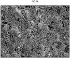
- Figs. 1A , 1B , 2A , 2B , 3A , and 3B illustrate scanning electron microscopic images (SEM images) of embodiment examples of the heat resistant porous layer included in the first separator.
- the heat resistant porous layers illustrated in Figs. 1A , 1B , 2A , 2B , 3A , and 3B also contain inorganic particles.
- the porous coating film contains a wholly aromatic polyamide.
- Fig. 1A is an SEM image of an outer surface (a surface farther from the porous substrate) of the heat resistant porous layer
- Fig. 1B is an SEM image of cross sections of the heat resistant porous layer and the porous substrate.
- the porous coating film is a coating film forming an outer surface of the heat resistant porous layer, and is a dense coating film having micropores.
- the porous coating film contains a polyamide imide.
- Fig. 2A is an SEM image of an outer surface (a surface farther from the porous substrate) of the heat resistant porous layer
- Fig. 2B is an SEM image of cross sections of the heat resistant porous layer and the porous substrate.
- the porous coating film is a coating film forming an outer surface of the heat resistant porous layer, and is a dense coating film having micropores.
- the porous coating film contains a polyimide.
- Fig. 3A is an SEM image of an outer surface (a surface farther from the porous substrate) of the heat resistant porous layer
- Fig. 3B is an SEM image of cross sections of the heat resistant porous layer and the porous substrate.
- the porous coating film is a coating film forming an outer surface of the heat resistant porous layer, and is a dense coating film having micropores.
- the adhesive layer in the first separator is a layer in which adhesive resin particles adhere to one or both sides of a layered body composed of the porous substrate and the heat resistant porous layer.
- the adhesive resin particles are formed of a particulate resin having adhesiveness to an electrode.
- the adhesive layer may have a structure in which a large number of adhesive resin particles are arranged adjacent to each other on a surface of the layered body, or may have a structure in which a large number of adhesive resin particles are scattered on a surface of the layered body.
- the adhesive layer may have a structure in which the adhesive resin particles are arranged in a single layer in a thickness direction, or may have a structure in which the adhesive resin particles are stacked in plural layers in the thickness direction.
- Figs. 1C , 2C , and 3C illustrate scanning electron microscopic images (SEM images) of embodiment examples of the adhesive layer included in the first separator.
- the heat resistant porous layer included in the first separator has a porous coating film containing at least one selected from the group consisting of a wholly aromatic polyamide, a polyamide imide, and a polyimide, which are heat resistant resins, and is thereby less likely to be peeled off from the porous substrate and has better toughness than a heat resistant porous layer formed by bonding inorganic particles to each other by a binder resin while having heat-resistance.
- the adhesive layer included in the first separator has a structure in which the adhesive resin particles adhere to the porous coating film of the heat resistant porous layer or the porous substrate, and is thereby hardly peeled off from the heat resistant porous layer or the porous substrate and has excellent toughness.
- the first separator is unlikely to cause interfacial destruction between layers and cohesive failure in each of the layers. As a result, it is presumed that the entire separator has a high adhesive strength to an electrode.
- the second separator for a non-aqueous secondary battery (also referred to as "second separator”) includes a porous substrate, a heat resistant porous layer that is provided on one side or on both sides of the porous substrate, and an adhesive layer that is provided on one side or on both sides of a layered body composed of the porous substrate and the heat resistant porous layer.
- the heat resistant porous layer in the second separator contains a heat resistant resin having at least one of an amide bond or an imide bond in a molecule and/or inorganic particles.
- the heat resistant porous layer thereby has heat resistance.
- the second separator has a peel strength between the porous substrate and the heat resistant porous layer of from 5 N/m to 75 N/m.
- the peel strength between the porous substrate and the heat resistant porous layers is in the above range on both sides of the porous substrate.
- the adhesive layer in the second separator is a layer in which adhesive resin particles adhere to one or both sides of a layered body composed of the porous substrate and the heat resistant porous layer.
- the adhesive resin particles are formed of a particulate resin having adhesiveness to an electrode.
- the adhesive layer may have a structure in which a large number of adhesive resin particles are arranged adjacent to each other on a surface of the layered body, or may have a structure in which a large number of adhesive resin particles are scattered on a surface of the layered body.
- the adhesive layer may have a structure in which the adhesive resin particles are arranged in a single layer in a thickness direction, or may have a structure in which the adhesive resin particles are stacked in plural layers in the thickness direction.
- Fig. 4A illustrates a scanning electron microscopic image (SEM image) of an embodiment example of the adhesive layer included in the second separator.
- the second separator has a peel strength between the porous substrate and the heat resistant porous layer of from 5 N/m to 75 N/m, and the heat resistant porous layer is hardly peeled off from the porous substrate.
- the adhesive layer included in the second separator has a structure in which the adhesive resin particles adhere to the heat resistant porous layer or the porous substrate, and is thereby hardly peeled off from the heat resistant porous layer or the porous substrate.
- the second separator is unlikely to cause interfacial destruction between layers. As a result, it is presumed that the entire separator has a high adhesive strength to an electrode.
- FIG. 5A to 5D is a schematic cross-sectional view of an embodiment example of the separator of the present disclosure.
- Each of Figs. 5A to 5D is a schematic cross-sectional view mainly for explaining the order of stacking layers, and the structure of each of the layers is omitted or simplified.
- layers having similar functions are denoted by the same reference numeral and described.
- a separator 10A illustrated in Fig. 5A has heat resistant porous layers 30 disposed on both sides of a porous substrate 20, and has adhesive layers 50 disposed on both sides of a layered body 40 composed of the porous substrate 20 and the two heat resistant porous layers 30.
- a separator 10B illustrated in Fig. 5B has the heat resistant porous layers 30 disposed on both sides of the porous substrate 20, and has the adhesive layer 50 disposed on one side of the layered body 40 composed of the porous substrate 20 and the two heat resistant porous layers 30.
- a separator 10C illustrated in Fig. 5C has the heat resistant porous layer 30 disposed on one side of the porous substrate 20, and has the adhesive layers 50 disposed on both sides of the layered body 40 composed of the porous substrate 20 and the one heat resistant porous layer 30.
- a separator 10D illustrated in Fig. 5D has the heat resistant porous layer 30 disposed on one side of the porous substrate 20, and has the adhesive layer 50 disposed on one side of the layered body 40 composed of the porous substrate 20 and the one heat resistant porous layer 30.
- the adhesive layer 50 is disposed on a surface of the heat resistant porous layer 30.
- the heat resistant porous layer 30 is disposed on a surface of the porous substrate 20.
- the heat resistant porous layer 30 may be provided only on one side of the porous substrate 20, or may be provided on both sides of the porous substrate 20.
- the heat resistance of the separator is better, and the safety of a battery can be further improved.
- the separator is less likely to be curled, and has excellent handleability during production of a battery.
- the separator has better ion permeability.
- the thickness of the entire separator can be suppressed, and a battery having a higher energy density can be produced.
- the adhesive layer 50 is disposed on a surface of the porous substrate 20 or the heat resistant porous layer 30, and exists as an outermost layer of the separator.
- the adhesive layer 50 may be provided only on one side of the layered body 40 or may be provided on both sides of the layered body 40. In a case where the adhesive layer 50 is provided only on one side of the layered body 40, the adhesive layer 50 is preferably disposed on a surface of the heat resistant porous layer 30. Whether the adhesive layer 50 is disposed on one side or both sides of the layered body 40 may be selected according to the composition or surface properties of a positive or a negative electrode of a battery. When the adhesive layer 50 is provided only on one side of the layered body 40, the thickness of the entire separator can be suppressed, and a battery having a higher energy density can be produced.
- the adhesive layer 50 is a layer in which the adhesive resin particles 52 adhere to a surface of the layered body 40.
- the adhesive layer 50 has a structure in which a large number of the adhesive resin particles 52 are arranged adjacent to each other on a surface of the layered body 40, and has a structure in which the adhesive resin particles 52 are arranged in a single layer in a thickness direction.
- the structure of the adhesive layer 50 is not limited to the above structure.
- the adhesive layer 50 may have a structure in which the large number of adhesive resin particles 52 are scattered on a surface of the layered body 40, or a structure in which the adhesive resin particles 52 are stacked in plural layers in a thickness direction.
- the adhesive layer 50 preferably has a structure in which the large number of adhesive resin particles 52 are arranged adjacent to each other on a surface of the layered body 40 from a viewpoint of better adhesiveness to an electrode, and preferably has a structure in which the adhesive resin particles 52 are arranged in a single layer in a thickness direction from a viewpoint of increasing the energy density of a battery.
- the porous substrate in the present disclosure refers to a substrate having pores or voids therein.
- a microporous film As the substrate, a microporous film; a porous sheet such as non-woven fabric and paper, composed of a fibrous material; and the like may be listed.
- microporous film is preferable.
- the microporous film refers to a film having plural micropores therein, having a structure in which these micropores are connected to each other, and allowing gas or liquid to pass from one surface to the other surface.
- materials having electrical insulation are preferably used and any of organic materials and inorganic materials may be used.
- the porous substrate contains a thermoplastic resin, from a viewpoint of imparting a shutdown function to the porous substrate.
- the shutdown function refers to a function of dissolving the constituent material to clog the pores of the porous substrate, thereby blocking ionic migration, and preventing thermal runaway of a battery, when the battery temperature is raised.
- the thermoplastic resin a thermoplastic resin having a melting point less than 200 °C is preferred.
- the thermoplastic resin for example, polyesters such as polyethylene terephthalate; polyolefins such as polyethylene and polypropylene; and the like may be mentioned, and among them, polyolefins are preferred.
- a microporous film containing polyolefin As the porous substrate, a microporous film containing polyolefin (referred to as "polyolefin microporous film") is preferred.
- polyolefin microporous film for example, a polyolefin microporous film which is applied to the conventional separator for a non-aqueous secondary battery may be mentioned, and among them, it is preferred to select those having sufficient mechanical properties and ion permeability.
- the polyolefin microporous film contains polyethylene, from the viewpoint of exhibiting the shutdown function, and the content of polyethylene is preferably 95 % by mass or more with respect to the total mass of the polyolefin microporous film.
- the microporous film contains polypropylene, from the viewpoint of imparting thermal resistance to the extent that the film is not easily broken when exposed to a high temperature.
- the polyolefin microporous film contains polyethylene and polypropylene, from the viewpoint of imparting shutdown function and thermal resistance that the film is not easily broken when exposed to a high temperature.
- a microporous film in which polyethylene and polypropylene are present in a mixed state in a layer may be listed. It is preferred that the microporous film contains 95 % by mass or more of polyethylene and 5 % by mass or less of polypropylene, from the viewpoint of compatibility of the shutdown function and thermal resistance.
- a polyolefin having a weight-average molecular weight (Mw) of from 100,000 to 5,000,000 is preferred.
- Mw weight-average molecular weight
- the polyolefin has a Mw of 100,000 or more, sufficient mechanical properties may be provided to the microporous film.
- the polyolefin has a Mw of 5,000,000 or less, the shutdown characteristic of the microporous film is good, and film molding of the microporous film is easy.
- Examples of the method for manufacturing the polyolefin microporous film include, a method containing extruding a molten polyolefin resin from a T-die to form a sheet, crystallizing and elongating the sheet, and further subjecting the sheet to heat treatment, thereby obtaining a microporous film; and a method containing extruding a polyolefin resin melted with a plasticizer such as liquid paraffin from a T-die, cooling it to form a sheet, elongating the sheet, extracting the plasticizer, and performing heat treatment, thereby obtaining a microporous film.
- a plasticizer such as liquid paraffin
- non-woven fabric composed of fibrous materials such as polyesters such as polyethylene terephthalate; polyolefins such as polyethylene and polypropylene; thermal resistant resins such as wholly aromatic polyamide, polyamide imide, polyimide, polyethersulfone, polysulfone, polyetherketone and polyetherimide; cellulose; and the like, or paper may be mentioned.
- the surface of the porous substrate may be subjected to various surface treatments within the range of not impairing the nature of the porous substrate, for the purpose of improving wettability with the coating liquid for forming the heat resistant porous layer or the dispersing liquid for resin particles for forming the adhesive porous layer.
- the surface treatment corona treatment, plasma treatment, flame treatment, UV irradiation treatment, and the like may be mentioned.
- the thickness of the porous substrate is preferably 10.0 ⁇ m or less, more preferably 8.0 ⁇ m or less, from the viewpoint of enhancing energy density of the battery, and is preferably 3.0 ⁇ m or more, more preferably 5.0 ⁇ m or more, from the viewpoint of production yield of the separator and production yield of the battery.
- the Gurley value of the porous substrate is preferably from 50 sec/100 ml to 400 sec/100 ml, more preferably from 50 sec/100 ml to 200 sec/100 ml, from the viewpoint of preventing short circuit a battery or obtaining sufficient ion permeability.
- the porosity of the porous substrate is from 20 to 60%, from the viewpoint of obtaining proper film resistance or shutdown function.
- the porosity of each of the porous substrate is determined according to the following calculation method.
- the piercing strength of the porous substrate is preferably 200g or more from the viewpoint of improving a production yield of the separator and production yield of the battery.
- the piercing strength of the porous substrate is measured by performing a piercing test under the condition of a curvature radius of a needle tip of 0.5 mm, and a piercing speed of 2 mm/sec, using a KES-G5 handy compression tester from KATO TECH CO., LTD., to obtain a maximum piercing load (g).
- the heat resistant porous layer in the first separator has a porous coating film containing at least one selected from the group consisting of a wholly aromatic polyamide, a polyamide imide, and a polyimide.
- the porous coating film is a coating film having a large number of micropores and allowing gas or liquid to pass therethrough from one surface to the other.
- the porous coating film can be confirmed with a scanning electron microscope. By observing a cross section of the separator or observing an outer surface of the heat resistant porous layer from a direction perpendicular to the surface, a resin portion forming the outer surface of the heat resistant porous layer and spreading like a film can be observed, and it can be observed that a large number of pores are formed in the resin portion.
- the dense porous coating film having micropores can be formed on a porous substrate by adjusting the composition of a coating liquid or a coagulation liquid in a wet coating method described below.
- the heat resistant porous layer has the porous coating film
- the adhesive layer in a form in which the adhesive layer is disposed on a surface of the heat resistant porous layer, due to adhesion of the adhesive resin particles to the porous coating film, interfacial destruction between the heat resistant porous layer and the adhesive layer hardly occurs.
- the heat resistant porous layer has excellent toughness, and cohesive failure of the heat resistant porous layer hardly occurs.
- the porous coating film is a dense coating film forming an outer surface of the heat resistant porous layer and having micropores.
- the average pore diameter of the micropores of the porous coating film is preferably 1000 nm or less, more preferably 800 nm or less, and still more preferably 500 nm or less from a viewpoint that the adhesive resin particles are hardly peeled off from the heat resistant porous layer, and is preferably 1 nm or more, more preferably 5 nm or more, and still more preferably 10 nm or more from a viewpoint of ion permeability.
- the coverage of the porous coating film on an outer surface of the heat resistant porous layer is preferably 60% or more, more preferably 70% or more, and still more preferably 80% or more with respect to the area of the heat resistant porous layer in planar view.
- a wholly aromatic polyamide is suitable for the heat resistant porous layer from a viewpoint of durability among heat resistant resins.
- a meta type or para type wholly aromatic polyamide may be used.
- wholly aromatic polyamides a meta type wholly aromatic polyamide is preferable from viewpoints of easy formation of a porous layer and excellent oxidation-reduction resistance in an electrode reaction.
- a wholly aromatic polyamide specifically, polymetaphenylene isophthalamide or polyparaphenylene terephthalamide is preferable, and polymetaphenylene isophthalamide is more preferable.
- the weight average molecular weight of the wholly aromatic polyamide contained in the heat resistant porous layer is preferably from 1 ⁇ 10 3 to 1 ⁇ 10 7 , more preferably from 5 ⁇ 10 3 to 5 ⁇ 10 6 , and still more preferably from 1 ⁇ 10 4 to 1 ⁇ 10 6 .
- a polyamide imide is suitable for the heat resistant porous layer from a viewpoint of heat resistance among heat resistant resins.
- the weight average molecular weight of a polyamide imide contained in the heat resistant porous layer is preferably from 1 ⁇ 10 3 to 1 ⁇ 10 7 , more preferably from 5 ⁇ 10 3 to 5 ⁇ 10 6 , and still more preferably from 1 ⁇ 10 4 to 1 ⁇ 10 6 .
- a polyimide is suitable for the heat resistant porous layer from a viewpoint of heat resistance among heat resistant resins.
- a polyimide an aliphatic polyimide or an aromatic polyimide may be used.
- the weight average molecular weight of a polyimide contained in the heat resistant porous layer is preferably from 1 ⁇ 10 3 to 1 ⁇ 10 7 , more preferably from 5 ⁇ 10 3 to 5 ⁇ 10 6 , and still more preferably from 1 ⁇ 10 4 to 1 ⁇ 10 6 .
- the heat resistant porous layer in the first separator may contain a heat resistant resin other than a wholly aromatic polyamide, a polyamide imide, and a polyimide.
- a heat resistant resin other than a wholly aromatic polyamide, a polyamide imide, and a polyimide examples include a polysulfone, a polyethersulfone, a polyketone, a polyetherketone, a polyetherimide, a cellulose, and a polyvinylidene fluoride type resin. These heat resistant resins may be used singly or in combination of two or more kinds thereof.
- the content of the heat resistant resin other than a wholly aromatic polyamide, a polyamide imide, and a polyimide is preferably from 0% by mass to 50% by mass, more preferably from 0% by mass to 40% by mass, and still more preferably from 0% by mass to 30% by mass with respect to the total amount of all the resins contained in the heat resistant porous layer in order to maintain an effect of the wholly aromatic polyamide, the polyamide imide, or the polyimide.
- the total amount of a wholly aromatic polyamide, a polyamide imide, and a polyimide contained in the heat resistant porous layer in the first separator is preferably 50% by mass or more, more preferably 70% by mass or more, and still more preferably 90% by mass or more with respect to the total amount of all the resins contained in the heat resistant porous layer.
- the heat resistant porous layer in the first separator preferably contains inorganic particles from a viewpoint of heat resistance.
- the inorganic particles are contained in the heat resistant porous layer, for example, in a state of being bonded to each other and covered by the porous coating film.
- the inorganic particles include particles of metal hydroxides such as aluminium hydroxide, magnesium hydroxide, calcium hydroxide, chromium hydroxide, zirconium hydroxide, cerium hydroxide, nickel hydroxide, or boron hydroxide; particles of metal oxides such as silica, alumina, zirconia or magnesium oxide; particles of carbonates such as calcium carbonate or magnesium carbonate; particles of sulfates such as barium sulfate or calcium sulfate.
- particles of metal hydroxides or particles of metal oxides are preferable, from the viewpoint of stability to an electrolyte and electrochemical stability.
- the inorganic particles that are surface-modified with a silane coupling agent or the like can also be used.
- the particle shape of the inorganic particles may be any shape, and may be spherical, elliptical, plate-shaped, needle-shaped, or irregular. From the viewpoint of preventing a short circuit of a battery, the inorganic particles contained in the heat resistant porous layer are preferably plate-shaped particles or primary particles that are not aggregated.
- the inorganic particles may be used singly or in combination of two or more kinds thereof.
- the volume average particle diameter of the inorganic particles is preferably from 0.01 ⁇ m to 10 ⁇ m.
- the lower limit thereof is more preferably 0.1 ⁇ m, and the upper limit thereof is more preferably 5 ⁇ m.
- the particle size distribution of the inorganic particles is preferably 0.1 ⁇ m ⁇ d90 - d10 ⁇ 3 ⁇ m.
- d10 represents the particle diameter ( ⁇ m) to which the cumulative total of the particles in the particle size distribution from the smaller particle size side is 10% by mass
- d90 represents the particle diameter ( ⁇ m) to which the cumulative total of the particles in the particle size distribution from the smaller particle size side is 90% by mass.
- the particle size distribution measurement is performed, for example, by using a laser diffraction particle size analyzer (for example, Mastersizer 2000, manufactured by Sysmex Corporation), by using water as a dispersion medium, and by using a small amount of a nonionic surfactant, Triton X-100, as a dispersant.
- the mass ratio of the inorganic particles in the heat resistant porous layer is preferably 50% by mass or more, more preferably 55% by mass or more, and still more preferably 60% by mass or more from a viewpoint of heat resistance.
- the mass ratio of the inorganic particles in the heat resistant porous layer is preferably 90% by mass or less, more preferably 85% by mass or less, and still more preferably 80% by mass or less from a viewpoint that the heat resistant porous layer is hardly peeled off from the porous substrate.
- the heat resistant porous layer in the first separator may contain an organic filler.
- the organic filler is contained in the heat resistant porous layer in a state where particles thereof are bonded to each other and covered by the porous coating film.
- Examples of the organic filler include crosslinked polymer particles of a crosslinked poly(meth)acrylic acid, a crosslinked poly(meth)acrylic acid ester, a crosslinked polysilicone, a crosslinked polystyrene, a crosslinked polydivinylbenzene, a crosslinked product of a styrene-divinylbenzene copolymer, a melamine resin, a phenol resin, a benzoguanamine-formaldehyde condensate, or the like; and heat resistant polymer particles of polysulfone, polyacrylonitrile, aramide, polyacetal, or the like.
- the organic filler may be used singly or in combination of two or more thereof.
- the heat resistant porous layer in the first separator may contain an additive, for example, a dispersing agent such as a surfactant, a wetting agent, a defoamer, a pH adjusting agent or the like.
- a dispersing agent such as a surfactant, a wetting agent, a defoamer, a pH adjusting agent or the like.
- the dispersing agent is added to the coating liquid for forming the heat resistant porous layer, for the purpose of improving dispersibility, coatability and preservation stability.
- the wetting agent, defoamer and pH adjusting agent are added to the coating liquid for forming the heat resistant porous layer, for example, for being well-mixed with the porous substrate, for suppressing air entrainment to the coating liquid, or for pH adjustment.
- the heat resistant porous layer in the second separator contains a heat resistant resin having at least one of an amide bond or an imide bond in a molecule and/or inorganic particles.
- the heat resistant porous layer has a large number of micropores, and allows gas or liquid to pass therethrough from one surface to the other surface.
- the heat resistant resin having at least one of an amide bond or an imide bond in a molecule is referred to as "specific heat resistant resin”.
- the specific heat resistant resin in the heat resistant porous layer may be a fibril-like coating film or a porous coating film (details will be described later) to form a three-dimensional network structure, or may be contained as a binder resin for connecting inorganic particles to each other.
- the specific heat resistant resin in the heat resistant porous layer may be formed of resin particles, and the resin particles of the specific heat resistant resin may be connected to each other, or the resin particles of the specific heat resistant resin may be connected to the inorganic particles to form a heat resistant porous layer.
- thermo resistant resin heat resistant resin having at least one of an amide bond or an imide bond in a molecule
- examples of the specific heat resistant resin include a wholly aromatic polyamide, a polyamide imide, a polyimide, and a polyetherimide. These resins may be used singly or in combination of two or more kinds thereof.
- the weight average molecular weight of the specific heat resistant resin contained in the heat resistant porous layer is preferably from 1 ⁇ 10 3 to 1 ⁇ 10 7 , more preferably from 5 ⁇ 10 3 to 5 ⁇ 10 6 , and still more preferably from 1 ⁇ 10 4 to 1 ⁇ 10 6 .
- a wholly aromatic polyamide is preferable from a viewpoint of durability.
- a meta type or para type wholly aromatic polyamide may be used.
- wholly aromatic polyamides a meta type wholly aromatic polyamide is preferable from viewpoints of easy formation of a porous layer and excellent oxidation-reduction resistance in an electrode reaction.
- a wholly aromatic polyamide specifically, polymetaphenylene isophthalamide or polyparaphenylene terephthalamide is preferable, and polymetaphenylene isophthalamide is more preferable.
- the weight average molecular weight of the wholly aromatic polyamide contained in the heat resistant porous layer is preferably from 1 ⁇ 10 3 to 1 ⁇ 10 7 , more preferably from 5 ⁇ 10 3 to 5 ⁇ 10 6 , and still more preferably from 1 ⁇ 10 4 to 1 ⁇ 10 6 .
- the heat resistant porous layer in the second separator may contain a heat resistant resin other than the specific heat resistant resin.
- the heat resistant resin other than the specific heat resistant resin include a polysulfone, a polyether sulfone, a polyketone, a polyether ketone, a cellulose, and a polyvinylidene fluoride type resin. These heat resistant resins may be used singly or in combination of two or more kinds thereof.
- the content of the heat resistant resin other than the specific heat resistant resin is preferably from 0% by mass to 50% by mass, more preferably from 0% by mass to 40% by mass, and still more preferably from 0% by mass to 30% by mass with respect to the total amount of all the resins contained in the heat resistant porous layer in order to maintain an effect of the specific heat resistant resin.
- the total amount of the specific heat resistant resins contained in the heat resistant porous layer is preferably 50% by mass or more, more preferably 70% by mass or more, and still more preferably 90% by mass or more with respect to the total amount of all the resins contained in the heat resistant porous layer.
- the heat resistant porous layer in the second separator contains inorganic particles
- the heat resistant porous layer does not need to contain the specific heat resistant resin.
- the heat resistant porous layer contains the inorganic particles and a binder resin (for example, an acrylic type resin).
- the heat resistant porous layer in the second separator preferably contains inorganic particles, from the viewpoint of heat resistance.
- the inorganic particles include particles of metal hydroxides such as aluminium hydroxide, magnesium hydroxide, calcium hydroxide, chromium hydroxide, zirconium hydroxide, cerium hydroxide, nickel hydroxide, or boron hydroxide; particles of metal oxides such as silica, alumina, zirconia or magnesium oxide; particles of carbonates such as calcium carbonate or magnesium carbonate; particles of sulfates such as barium sulfate or calcium sulfate.
- particles of metal hydroxides or particles of metal oxides are preferable, from the viewpoint of stability to an electrolyte and electrochemical stability.
- the inorganic particles that are surface-modified with a silane coupling agent or the like can also be used.
- the particle shape of the inorganic particles may be any shape, and may be spherical, elliptical, plate-shaped, needle-shaped, or irregular. From the viewpoint of preventing a short circuit of a battery, the inorganic particles contained in the heat resistant porous layer are preferably plate-shaped particles or primary particles that are not aggregated.
- the inorganic particles may be used singly or in combination of two or more kinds thereof.
- the volume average particle diameter of the inorganic particles is preferably from 0.01 ⁇ m to 10 ⁇ m.
- the lower limit thereof is more preferably 0.1 ⁇ m, and the upper limit thereof is more preferably 5 ⁇ m.
- the particle size distribution of the inorganic particles is preferably 0.1 ⁇ m ⁇ d90 - d10 ⁇ 3 ⁇ m.
- d10 represents the particle diameter ( ⁇ m) to which the cumulative total of the particles in the particle size distribution from the smaller particle size side is 10% by mass
- d90 represents the particle diameter ( ⁇ m) to which the cumulative total of the particles in the particle size distribution from the smaller particle size side is 90% by mass.
- the particle size distribution measurement is performed, for example, by using a laser diffraction particle size analyzer (for example, Mastersizer 2000, manufactured by Sysmex Corporation), by using water as a dispersion medium, and by using a small amount of a nonionic surfactant, Triton X-100, as a dispersant.
- the mass ratio of the inorganic particles in the heat resistant porous layer is preferably 50% by mass or more, more preferably 55% by mass or more, and still more preferably 60% by mass or more from a viewpoint of heat resistance.
- the mass ratio of the inorganic particles in the heat resistant porous layer is preferably 90% by mass or less, more preferably 85% by mass or less, and still more preferably 80% by mass or less from a viewpoint that the heat resistant porous layer is hardly peeled off from the porous substrate.
- the heat resistant porous layer in the second separator contains at least the specific heat resistant resin and further contains inorganic particles.
- the heat resistant porous layer in the second separator preferably has a porous coating film containing the specific heat resistant resin.
- the porous coating film is a coating film having a large number of micropores and allowing gas or liquid to pass therethrough from one surface to the other.
- the porous coating film can be confirmed with a scanning electron microscope. By observing a cross section of the separator or observing an outer surface of the heat resistant porous layer from a direction perpendicular to the surface, a resin portion forming the outer surface of the heat resistant porous layer and spreading like a film can be observed, and it can be observed that a large number of pores are formed in the resin portion.
- the dense porous coating film having micropores can be formed on a porous substrate by adjusting the composition of a coating liquid or a coagulation liquid in a wet coating method described below.
- Examples of the form of the heat resistant porous layer having a porous coating film include the following forms (a') to (d').
- Preferable forms kind, molecular weight, size, shape, and the like) of the specific heat resistant resin and the inorganic particles in forms (a') to (d') are as described above.
- Figs. 4B and 4C illustrate scanning electron microscopic images (SEM images) of an embodiment example of the heat resistant porous layer included in the second separator.
- the heat resistant porous layer illustrated in Figs. 4B and 4C contains the specific heat resistant resin and inorganic particles.
- Fig. 4B is an SEM image of an outer surface (a surface farther from the porous substrate) of the heat resistant porous layer
- Fig. 4C is an SEM image of cross sections of the heat resistant porous layer and the porous substrate.
- the porous coating film is a coating film forming an outer surface of the heat resistant porous layer, and is a dense coating film having micropores.
- the heat resistant porous layer in the second separator has the porous coating film
- the adhesive layer in a form in which the adhesive layer is disposed on a surface of the heat resistant porous layer, due to adhesion of the adhesive resin particles to the porous coating film, interfacial destruction between the heat resistant porous layer and the adhesive layer hardly occurs.
- the heat resistant porous layer has excellent toughness, and cohesive failure of the heat resistant porous layer hardly occurs.
- the heat resistant porous layer in the second separator may contain an organic filler.
- the organic filler is contained in the heat resistant porous layer, for example, in a state where particles thereof are bonded to each other by the specific heat resistant resin or in a state where particles thereof are bonded to each other and covered by the porous coating film.
- Examples of the organic filler include crosslinked polymer particles of a crosslinked poly(meth)acrylic acid, a crosslinked poly(meth)acrylic acid ester, a crosslinked polysilicone, a crosslinked polystyrene, a crosslinked polydivinylbenzene, a crosslinked product of a styrene-divinylbenzene copolymer, a melamine resin, a phenol resin, a benzoguanamine-formaldehyde condensate, or the like; and heat resistant polymer particles of polysulfone, polyacrylonitrile, aramide, polyacetal, or the like.
- the organic filler may be used singly or in combination of two or more thereof.
- the heat resistant porous layer in the second separator may contain an additive, for example, a dispersing agent such as a surfactant, a wetting agent, a defoamer, a pH adjusting agent or the like.
- a dispersing agent such as a surfactant, a wetting agent, a defoamer, a pH adjusting agent or the like.
- the dispersing agent is added to the coating liquid for forming the heat resistant porous layer, for the purpose of improving dispersibility, coatability and preservation stability.
- the wetting agent, defoamer and pH adjusting agent are added to the coating liquid for forming the heat resistant porous layer, for example, for being well-mixed with the porous substrate, for suppressing air entrainment to the coating liquid, or for pH adjustment.
- the thickness of the heat resistant porous layer is preferably 0.5 ⁇ m or more on one surface and more preferably 1.0 ⁇ m or more on one surface from a viewpoint of heat resistance or handleability of the separator, and is preferably 5.0 ⁇ m or less on one surface, and more preferably 4.0 ⁇ m or less on one surface from a viewpoint of handleability of the separator or energy density of a battery.
- the thickness of the heat resistant porous layer is preferably 1.0 ⁇ m or more, more preferably 2.0 ⁇ m or more, and preferably 10.0 ⁇ m or less, more preferably 8.0 ⁇ m or less as a total thickness thereof on both surfaces of the porous substrate even if the heat resistant porous layer is provided only on one surface of the porous substrate or on both surfaces thereof.
- the weight of the heat resistant porous layer in the separator of the present disclosure is, as a total weight thereof on both surfaces, preferably 1.0 g/m 2 or more and more preferably 2.0 g/m 2 or more from a viewpoint of heat resistance or handleability of the separator, and is preferably 10.0 g/m 2 or less, and more preferably 8.0 g/m 2 or less from a viewpoint of handleability of the separator or energy density of a battery.
- the porosity of the heat resistant porous layer is preferably 40% or more, more preferably 50% or more, and still more preferably 60% or more from a viewpoint of ion permeability of the separator, and is preferably 90% or less, more preferably 80% or less, and still more preferably 70% or less from a viewpoint of thermal dimensional stability of the separator.
- a method of determining the porosity of the heat resistant porous layer is similar to a method of determining the porosity of the porous substrate.
- the peel strength between the porous substrate and the heat resistant porous layer is preferably 5 N/m or more, more preferably 10 N/m or more, still more preferably 15 N/m or more, and further still more preferably 20 N/m or more from a viewpoint of the adhesive strength of the separator to an electrode.
- the peel strength is preferably 75 N/m or less, more preferably 60 N/m or less, and still more preferably 50 N/m or less from a viewpoint of ion permeability.
- the peel strength between the porous substrate and the heat resistant porous layers is preferably in the above range on both sides of the porous substrate.
- the adhesive layer has a structure in which adhesive resin particles adhere to one or both sides of the layered body composed of the porous substrate and the heat resistant porous layer.
- the adhesive layer allows gas or liquid to pass therethrough from one surface to the other surface by a gap existing between the adhesive resin particles.
- the structure in which the adhesive resin particles adhere includes, of course, a form in which a resin maintains a particle shape in a completed separator, and also includes a form in which some of resin particles are melted by a heat treatment or a drying treatment and do not maintain a particle shape in a separator completed by using resin particles as a material of the adhesive layer.
- the adhesive layer has a structure in which the adhesive resin particles adhere to the heat resistant porous layer or the porous substrate, interfacial destruction between the adhesive layer and the heat resistant porous layer or the porous substrate hardly occurs.
- the adhesive layer has a structure in which the adhesive resin particles adhere to each other and are connected to each other, the adhesive layer has excellent toughness, and cohesive failure of the adhesive layer hardly occurs.
- the adhesive resin particles are formed of a particulate resin having adhesiveness to an electrode of a battery.
- the kind of the resin of the adhesive resin particles may be selected according to the composition of a positive electrode or a negative electrode.
- the adhesive resin particles are preferably resin particles that are stable to an electrolytic solution and electrochemically stable.
- the adhesive resin particles include particles containing a polyvinylidene fluoride type resin, a fluorine type rubber, an acrylic type resin, a styrene-butadiene copolymer, a homopolymer or a copolymer of a vinyl nitrile compound (acrylonitrile, methacrylonitrile, or the like), carboxymethyl cellulose, a hydroxyalkyl cellulose, a polyvinyl alcohol, a polyvinyl butyral, a polyvinyl pyrrolidone, a polyether (polyethylene oxide, polypropylene oxide, or the like), or any mixture of two or more kinds thereof.
- particles containing a polyvinylidene fluoride type resin and/or an acrylic type resin are preferable from a viewpoint of excellent oxidation resistance.
- polyvinylidene fluoride type resin examples include a homopolymer of vinylidene fluoride (that is, polyvinylidene fluoride); a copolymer of vinylidene fluoride and another monomer (polyvinylidene fluoride copolymer); and a mixture of polyvinylidene fluoride and a polyvinylidene fluoride copolymer.
- Examples of the monomer copolymerizable with vinylidene fluoride include tetrafluoroethylene, hexafluoropropylene, trifluoroethylene, chlorotrifluoroethylene, trichloroethylene, vinyl fluoride, trifluoroperfluoropropyl ether, ethylene, (meth)acrylic acid, methyl (meth)acrylate, (meth)acrylate, vinyl acetate, vinyl chloride, and acrylonitrile. These monomers may be used singly or in combination of two or more kinds thereof.
- the polyvinylidene fluoride copolymer contained in the adhesive resin particles is preferably a copolymer having 50 mol% or more of structural units derived from vinylidene fluoride from a viewpoint of obtaining mechanical strength that can withstand pressurization and heating during production of a battery.
- the polyvinylidene fluoride copolymer contained in the adhesive resin particles is preferably a copolymer of vinylidene fluoride and tetrafluoroethylene, a copolymer of vinylidene fluoride and hexafluoropropylene, or a copolymer of vinylidene fluoride and trifluoroethylene, and more preferably a copolymer of vinylidene fluoride and hexafluoropropylene.
- the copolymer of vinylidene fluoride and hexafluoropropylene is preferably a copolymer containing 0.1 mol% to 10 mol% (preferably 0.5 mol% to 5 mol%) of structural units derived from hexafluoropropylene.
- the weight average molecular weight of polyvinylidene fluoride or a polyvinylidene fluoride copolymer contained in the adhesive resin particles is preferably from 1000 to 5,000,000, more preferably from 10,000 to 3,000,000, and still more preferably from 50,000 to 2,000,000.
- acrylic type resin contained in the adhesive resin particles examples include a poly (meth)acrylic acid, a poly (meth)acrylate, a poly (meth)acrylic acid ester, a crosslinked poly (meth)acrylic acid, a crosslinked poly (meth)acrylate, and a crosslinked poly (meth)acrylic acid ester, and also include a modified acrylic type resin. These resins may be used singly or in combination of two or more kinds thereof.
- the acrylic type resin may be used as a mixture of polyvinylidene fluoride and an acrylic type resin or a mixture of a polyvinylidene fluoride copolymer and an acrylic type resin.
- the adhesive resin particles are preferably polyvinylidene fluoride particles, polyvinylidene fluoride copolymer particles, particles of a mixture of polyvinylidene fluoride and a polyvinylidene fluoride copolymer, particles of a mixture of polyvinylidene fluoride and an acrylic type resin, or particles of a mixture of a polyvinylidene fluoride copolymer and an acrylic type resin.
- the polyvinylidene fluoride copolymer is preferably a copolymer of vinylidene fluoride and tetrafluoroethylene, a copolymer of vinylidene fluoride and hexafluoropropylene, or a copolymer of vinylidene fluoride and trifluoroethylene.
- the mixture of polyvinylidene fluoride and an acrylic type resin or the mixture of a polyvinylidene fluoride copolymer and an acrylic type resin, constituting the adhesive resin particles, preferably contains 20% by mass or more of polyvinylidene fluoride or a polyvinylidene fluoride copolymer from a viewpoint of oxidation resistance.
- the adhesive resin particles two or more kinds of adhesive resin particles may be used in combination. It is preferable to use a mixture of first adhesive resin particles containing a polyvinylidene fluoride type resin and second adhesive resin particles containing an acrylic type resin from a viewpoint of adjusting the ion permeability of the adhesive layer, the adhesiveness of the adhesive layer to an electrode, the peel strength between the adhesive layer and the heat resistant porous layer, and the handleability of the adhesive layer in a well-balanced manner.
- the first adhesive resin particles (hereinafter, also referred to as "resin particles F") are particles containing a polyvinylidene fluoride type resin in an amount of more than 50% by mass with respect to the total solid content.
- the second adhesive resin particles (hereinafter, also referred to as "resin particles A”) are particles containing an acrylic type resin in an amount of more than 50% by mass with respect to the total solid content.
- polyvinylidene fluoride type resin contained in the resin particles F examples include polyvinylidene fluoride, a polyvinylidene fluoride copolymer, and a mixture of polyvinylidene fluoride and a polyvinylidene fluoride copolymer, and preferable forms of these polymers are as described above.
- the resin particles F may contain a resin other than a polyvinylidene fluoride type resin.
- the amount of a polyvinylidene fluoride type resin contained in the resin particles F is more than 50% by mass, preferably 70% by mass or more, more preferably 90% by mass or more, and still more preferably 100% by mass with respect to the total solid content of the resin particles F.
- acrylic type resin contained in the resin particles A examples include a poly (meth)acrylic acid, a poly (meth)acrylate, a poly (meth)acrylic acid ester, a crosslinked poly (meth)acrylic acid, a crosslinked poly (meth)acrylate, and a crosslinked poly (meth)acrylic acid ester, and also include a modified acrylic type resin. These resins may be used singly or in combination of two or more kinds thereof.
- the resin particles A may contain a resin other than an acrylic type resin.
- the amount of an acrylic type resin contained in the resin particles A is more than 50% by mass, preferably 70% by mass or more, more preferably 90% by mass or more, and still more preferably 100% by mass with respect to the total solid content of the resin particles A.
- a mass ratio between the resin particles F and the resin particles A contained in the adhesive layer only needs to be adjusted according to characteristics required for the adhesive layer.
- the mixture of the resin particles F and the resin particles A is preferably a dispersion in which the resin particles F and the resin particles A are dispersed in a dispersion medium as a coating liquid used for producing the adhesive layer.
- the dispersion medium of the dispersion is not particularly limited as long as the dispersion medium does not dissolve a polyvinylidene fluoride type resin, an acrylic type resin, or the heat resistant porous layer, but is preferably water in terms of handling safety. That is, the dispersion is preferably an aqueous dispersion in which the resin particles F and the resin particles A are dispersed in water.
- Examples of a representative commercially available product of the aqueous dispersion in which the resin particles F and the resin particles A are dispersed in water include Aquatec FMA-12, Aquatec ARC, and Aquatec CRX manufactured by Arkema S.A.; and TRD202A manufactured by JSR Corporation.
- the aqueous dispersion in which the resin particles F and the resin particles A are dispersed in water may be prepared by dispersing the resin particles F and the resin particles A in water, or may be prepared by mixing an aqueous dispersion in which the resin particles F are dispersed in water with an aqueous dispersion in which the resin particles A are dispersed in water.
- aqueous dispersion in which the resin particles F are dispersed in water a known aqueous dispersion including a commercially available product can be used, or the known resin particles F including a commercially available product can be dispersed in water and used.
- Examples of a representative commercially available product of the aqueous dispersion in which the resin particles F are dispersed in water include LBG2200LX, LATEX32, and KYNAR WATERBORNE RC series (RC-10246, RC-10278, and RC-10280) manufactured by Arkema S.A.; XPH838 series, XPH882 series, XPH883 series, XPH884 series, XPH859 series, and XPH918 series manufactured by Solvay Specialty Polymers; and PVDF aqueous dispersion manufactured by Kureha Corporation.
- aqueous dispersion in which the resin particles A are dispersed in water a known aqueous dispersion including a commercially available product can be used, or the known resin particles A including a commercially available product can be dispersed in water and used.
- Examples of a representative commercially available product of the aqueous dispersion in which the resin particles A are dispersed in water include BM-120S manufactured by Zeon Corporation; and an aqueous dispersion of acrylic particles manufactured by DIC Corporation.
- the volume average particle diameter of the adhesive resin particles is preferably 0.01 ⁇ m or more, more preferably 0.03 ⁇ m or more, and still more preferably 0.05 ⁇ m or more from a viewpoint of forming a favorable porous structure, and is preferably 1.0 ⁇ m or less, more preferably 0.8 ⁇ m or less, and still more preferably 0.6 ⁇ m or less from a viewpoint of suppressing the thickness of the adhesive layer.
- the adhesive layer may contain a component other than the adhesive resin particles as long as the effects of the present disclosure are not impaired.
- the component include an additive added to a resin particle dispersion for forming the adhesive layer.
- the adhesive layer preferably contains 90% by mass or more of the adhesive resin particles, and more preferably 95% by mass or more of the adhesive resin particles with respect to the total amount of the layer. More preferably, the adhesive layer contains substantially only the adhesive resin particles.
- the adhesive layer in the separator of the present disclosure may contain an additive, for example, a dispersing agent such as a surfactant, a wetting agent, a defoamer, a pH adjusting agent or the like.
- a dispersing agent such as a surfactant, a wetting agent, a defoamer, a pH adjusting agent or the like.
- the dispersing agent is added to the coating liquid for forming the adhesive layer, for the purpose of improving dispersibility, coatability and preservation stability.
- the wetting agent, defoamer and pH adjusting agent are added to the coating liquid for forming the adhesive layer, for example, for being well-mixed with the porous substrate, for suppressing air entrainment to the coating liquid, or for pH adjustment.
- the surfactant contained in the resin particle dispersion for forming the adhesive layer examples include a non-reactive anionic surfactant such as alkyl sulfate, polyoxyethylene alkyl ether sulfate, alkylbenzene sulfonate, alkylnaphthalene sulfonate, alkyl sulfosuccinate, alkyl diphenyl ether disulfonate, naphthalene sulfonic acid formalin condensate, polyoxyethylene polycyclic phenyl ether sulfate, polyoxyethylene distyrenated phenyl ether sulfate, fatty acid salt, alkyl phosphate, or polyoxyethylene alkyl phenyl ether sulfate; a non-reactive nonionic surfactant such as polyoxyethylene alkyl ether, polyoxyalkylene alkyl ether, polyoxyethylene polycyclic phenyl ether, polyoxyethylene distyrenated
- an anionic surfactant that is a reactive surfactant examples include an ethylenically unsaturated monomer having a group selected from a sulfonic acid group, a sulfonate group, a sulfate group, or any salt thereof.
- the anionic surfactant that is a reactive surfactant is preferably a compound having a sulfonic acid group or a group which is an ammonium salt thereof or an alkali metal salt thereof (that is, an ammonium sulfonate group or an alkali metal sulfonate group).
- nonionic surfactant that is a reactive surfactant
- examples of a nonionic surfactant that is a reactive surfactant include ⁇ -[1-[(allyloxy) methyl]-2-(nonylphenoxy) ethyl]-co-hydroxypolyoxyethylene, polyoxyethylene alkylpropenyl phenyl ether, ⁇ -[2-[(allyloxy)-1-(alkyloxymethyl) ethyl]- ⁇ -hydroxypolyoxyethylene, and polyoxyethylene polyoxybutylene (3-methyl-3-butenyl) ether.
- the surfactants may be used singly or in combination of two or more kinds thereof.
- the adhesive layer further contains a surfactant.
- the surfactant contained in the adhesive layer is preferably at least one selected from the group consisting of a non-reactive anionic surfactant, a non-reactive nonionic surfactant, a reactive anionic surfactant, and a reactive nonionic surfactant.
- Specific examples of the non-reactive anionic surfactant, the non-reactive nonionic surfactant, the reactive anionic surfactant, and the reactive nonionic surfactant include specific examples described above as the surfactant contained in the resin particle dispersion for forming the adhesive layer.
- the mass ratio of the surfactant with respect to the total mass of the adhesive layer is preferably from 0.1% by mass to 10% by mass, and more preferably from 1% by mass to 8% by mass.
- the weight of the adhesive layer per surface is preferably 0.2 g/m 2 or more, more preferably 0.25 g/m 2 or more, and still more preferably 0.3 g/m 2 or more from a viewpoint of adhesiveness to an electrode, and is preferably 2.0 g/m 2 or less, more preferably 1.8 g/m 2 or less, and still more preferably 1.6 g/m 2 or less from a viewpoint of ion permeability, handleability of the separator, or energy density of a battery.
- the coverage of the adhesive resin particles in the adhesive layer is preferably 60% or more, more preferably 70% or more, and still more preferably 80% or more with respect to the area of the separator in planar view.
- the coverage of the adhesive resin particles in the adhesive layer is determined by imaging a surface of the separator from a direction perpendicular to the surface with a scanning electron microscope, randomly specifying 10 square regions, determining the coverages of the regions, and calculating an average value of the coverages of the 10 square areas.
- the separator of the present disclosure has a thickness of preferably 8.0 ⁇ m or more, more preferably 9.0 ⁇ m or more, from the viewpoint of mechanical strength of the separator, and preferably 20.0 ⁇ m or less, and more preferably 15.0 ⁇ m or less, from the viewpoint of energy density of a battery.
- the piercing strength of the separator of the present disclosure is preferably from 150 g to 1,000 g, more preferably from 200 g to 600 g, from the viewpoint of mechanical strength of a separator or the short-circuit resistance of a battery.
- the measurement method of the piercing strength of the separator is identical to the measurement method of the piercing strength of the porous substrate.
- the porosity of the separator of the present disclosure is from 30% to 60%, from the viewpoint of adhesiveness to the electrode, handleability of a separator, ion permeability, or mechanical strength.
- the film resistance of the separator of the present disclosure is preferably from 0.5 ohm ⁇ cm 2 to 10 ohm ⁇ cm 2 , and more preferably from 1 ohm ⁇ cm 2 to 8 ohm ⁇ cm 2 , from the viewpoint of the load characteristics of the battery.
- the Gurley value of the separator of the present disclosure is preferably from 50 sec/100 ml to 800 sec/100 ml, more preferably from 80 sec/100 ml to 500 sec/100 ml, still more preferably from 100 sec/100 ml to 400 sec/100 ml, from the viewpoint of good balance between mechanical strength and ion permeability.
- the separator of the present disclosure has the value obtained by subtracting the Gurley value of the porous substrate from the Gurley value of the separator (in a state that the heat resistant porous layer and the adhesive layer are formed on the porous substrate) is preferably 300 sec/100 ml or less, more preferably 200 sec/100 ml or less, and still more preferably 150 sec/100 ml or less, from the viewpoint of ion permeability.
- the lower limit of the value obtained by subtracting the Gurley value of the porous substrate from the Gurley value of the separator is preferably 20 sec/100 ml or more, from the viewpoint of providing adhesive resin particles in sufficient amount for adhering to the electrode.
- the tensile strength of the separator of the present disclosure in the MD direction is preferably 500 kgf/cm 2 or more, more preferably 600 kgf/cm 2 or more, and still more preferably 700 kgf/cm 2 or more from a viewpoint of mechanical strength of the separator or handleability thereof (fixing property of the adhesive layer).
- a higher tensile strength in the MD direction is more preferable from the above viewpoint, but is usually 3000 kgf/cm 2 or less.
- the tensile strength of the separator of the present disclosure in the TD direction is preferably 500 kgf/cm 2 or more, more preferably 600 kgf/cm 2 or more, and still more preferably 700 kgf/cm 2 or more from a viewpoint of mechanical strength of the separator or handleability thereof (fixing property of the adhesive layer).
- a higher tensile strength in the TD direction is more preferable from the above viewpoint, but is usually 3000 kgf/cm 2 or less.
- the tensile strength of the separator of the present disclosure can be controlled by, for example, the content of inorganic particles in the heat resistant porous layer, the thickness of the heat resistant porous layer, the porosity of the heat resistant porous layer, and the thickness of the adhesive layer.
- the first separator is produced by, for example, the following production method A or B.
- Production method B may be any one of the following forms B-1 to B-4.
- the heat resistant porous layer is formed on the porous substrate by a wet coating method.
- the second separator is produced by, for example, the following production method A or B.
- a method of forming the heat resistant porous layer may be a wet coating method or a dry coating method.
- Production method B may be any one of the following forms B-1 to B-7.
- the heat resistant porous layer is formed by the wet coating method.
- the heat resistant porous layer is formed by the dry coating method.
- the wet coating method is a method of solidifying a coating layer in a coagulation liquid
- the dry coating method is a method of drying a coating layer to solidify the coating layer
- Production method A non-continuous production method: A heat resistant porous layer is formed on a porous substrate fed from a roll to obtain a layered body composed of the porous substrate and the heat resistant porous layer, and then the layered body is once wound around another roll. Subsequently, an adhesive layer is formed on the layered body fed from the roll to obtain a separator, and the resulting separator is wound around another roll.
- Production method B (continuous production method): A heat resistant porous layer and an adhesive layer are continuously or simultaneously formed on a porous substrate fed from a roll, and the resulting separator is wound around another roll.
- a heat resistant porous layer is formed on at least one surface of a porous substrate by a wet coating method to obtain a layered body composed of the porous substrate and the heat resistant porous layer, and subsequently an adhesive layer is formed on at least one surface of the layered body by a dry coating method.
- Production method B of form B-1 includes the following steps (1) to (7), and sequentially performs steps (1) to (7).
- a heat resistant porous layer-forming coating liquid (hereinafter, referred to as "coating liquid” in description of the production method) is prepared by dissolving at least one selected from the group consisting of a wholly aromatic polyamide, a polyamide imide, and a polyimide in a solvent.
- coating liquid inorganic particles or another component are dispersed or dissolved, if necessary.
- a heat resistant porous layer-forming coating liquid (hereinafter, referred to as "coating liquid” in description of the production method) is prepared by dissolving or dispersing a specific heat resistant resin and/or inorganic particles in a solvent.
- coating liquid a resin other than the specific heat resistant resin or a component other than a resin is dissolved or dispersed, if necessary.
- the solvent used for preparing the coating liquid contains a solvent that dissolves at least one selected from the group consisting of a wholly aromatic polyamide, a polyamide imide, and a polyimide (hereinafter, also referred to as "good solvent").
- the good solvent include a polar amide solvent such as N-methylpyrrolidone, dimethylacetamide, dimethylformamide, or dimethylformamide.
- the solvent used for preparing the coating liquid contains a solvent that dissolves the specific heat resistant resin and/or another resin (hereinafter, also referred to as "good solvent").
- the good solvent include a polar amide solvent such as N-methylpyrrolidone, dimethylacetamide, dimethylformamide, or dimethylformamide.
- the solvent used for preparing the coating liquid preferably contains a phase separation agent that induces phase separation from a viewpoint of forming a porous layer having a favorable porous structure. Therefore, the solvent used for preparing the coating liquid is preferably a mixed solvent of a good solvent and a phase separation agent.
- the phase separation agent is preferably mixed with a good solvent in such an amount that a viscosity suitable for coating can be ensured. Examples of the phase separation agent include water, methanol, ethanol, propyl alcohol, butyl alcohol, butanediol, ethylene glycol, propylene glycol, and tripropylene glycol.
- the solvent used for preparing the coating liquid is preferably a mixed solvent of a good solvent and a phase separation agent, containing 60% by mass or more of the good solvent and 40% by mass or less of the phase separation agent from a viewpoint of forming a favorable porous structure.
- the resin concentration of a wholly aromatic polyamide, a polyamide imide, and a polyimide in the coating liquid is preferably from 1% by mass to 20% by mass from a viewpoint of forming a favorable porous structure.
- the resin concentration of the coating liquid is preferably from 1% by mass to 20% by mass from a viewpoint of forming a favorable porous structure.
- the adhesive resin particle dispersion is prepared by dispersing adhesive resin particles in water.
- a surfactant may be added to the adhesive resin particle dispersion in order to enhance the dispersibility of the adhesive resin particles in water.
- the adhesive resin particle dispersion may be a commercially available product or a diluent of a commercially available product.
- the concentration of the adhesive resin particles in the adhesive resin particle dispersion is preferably from 1% by mass to 60% by mass from a viewpoint of coating suitability.
- the coating liquid is applied to at least one surface of the porous substrate to form a coating layer on the porous substrate.
- a method of applying the coating liquid to the porous substrate include a knife coating method, a Meyer bar coating method, a die coating method, a reverse roll coating method, a roll coating method, a gravure coating method, a screen printing method, an ink jet method, and a spray method.
- the porous substrate having the coating layer formed thereon is immersed in a coagulation liquid to induce phase separation in the coating layer, at least one selected from the group consisting of a wholly aromatic polyamide, a polyamide imide, and a polyimide is solidified to form a porous coating film containing at least one selected from the group consisting of a wholly aromatic polyamide, a polyamide imide, and a polyimide.
- a layered body composed of the porous substrate and the heat resistant porous layer is obtained.
- the second separator In a case where the second separator is produced, while the porous substrate having the coating layer formed thereon is immersed in a coagulation liquid to induce phase separation in the coating layer, the specific heat resistant resin and/or another resin is solidified to form a heat resistant porous layer. As a result, a layered body composed of the porous substrate and the heat resistant porous layer is obtained.
- the coagulation liquid generally contains the good solvent and the phase separation agent used for preparing the coating liquid, and water.
- a mixing ratio between the good solvent and the phase separation agent is preferably matched with the mixing ratio of the mixed solvent used for preparing the coating liquid in terms of production.
- the content of water in the coagulation liquid is preferably from 40% by mass to 90% by mass from viewpoints of formation of a porous structure and productivity.
- the temperature of the coagulation liquid is, for example, from 20°C to 50°C.
- the layered body is withdrawn from the coagulation liquid and washed with water.
- the coagulation liquid is removed from the layered body.
- water is removed from the layered body. Washing is performed, for example, by transporting the layered body in a water washing bath. Drying is performed, for example, by transporting the layered body in a high-temperature environment, blowing air to the layered body, or bringing the layered body into contact with a heat roll.
- the drying temperature is preferably from 40°C to 80°C.
- the adhesive resin particle dispersion is applied to at least one side of the layered body.
- a method of applying the adhesive resin particle dispersion include a knife coating method, a gravure coating method, a Meyer bar coating method, a die coating method, a reverse roll coating method, a roll coating method, a screen printing method, an ink jet method, and a spray method.
- the adhesive resin particle dispersion on the layered body is dried to cause the adhesive resin particles to adhere to a surface of the layered body. Drying is performed, for example, by transporting the layered body in a high-temperature environment, or by blowing air to the layered body.
- the drying temperature is preferably from 40°C to 100°C.
- Production method A for producing the first separator or production method B of forms B-2 to B-4 can be performed by partially omitting or changing the above steps (1) to (7).
- Production method A for producing the second separator or production method B of forms B-2 to B-7 can be performed by partially omitting or changing the above steps (1) to (7).
- the non-aqueous secondary battery according to the present disclosure is a non-aqueous secondary battery in which an electromotive force is obtained by doping and dedoping lithium.
- the non-aqueous secondary battery includes a positive electrode, a negative electrode, and the separator for a non-aqueous secondary battery according to the present disclosure.
- the term "dope” means occlusion, support, adsorption, or insertion, and means a phenomenon in which a lithium ion enters into an active material of an electrode such as a positive electrode or the like.
- the non-aqueous secondary battery according to the present disclosure has a structure, for example, in which a battery element, in which a negative electrode and a positive electrode face each other via a separator, is impregnated with an electrolyte and is enclosed in an outer casing.
- the non-aqueous secondary battery according to the present disclosure is suitable for non-aqueous electrolyte secondary batteries and, in particular, for lithium ion secondary batteries.
- the separator according to the present disclosure is excellent in adhesiveness to an electrode, so that the non-aqueous secondary battery according to the present disclosure exhibits excellent productivity of a battery and has excellent cycle characteristics (capacity retention rate) of a battery.
- Examples of an embodiment of the positive electrode include a structure in which an active material layer containing a positive electrode active material and a binder resin is formed on a current collector.
- the active material layer may further contain a conductive auxiliary agent.
- Examples of the positive electrode active material include a lithium-containing transition metal oxide, and specific examples thereof include LiCoO2, LiNiO 2 , LiMn 1/2 Ni 1/2 O 2 , LiCO 1/3 Mn 1/3 Ni 1/3 O 2 , LiMn 2 O 4 , LiFePO 4 , LiCo 1/2 Ni 1/2 O 2 , and LiAl 1/4 Ni 3/4 O 2 .
- Examples of the binder resin include a polyvinylidene fluoride type resin, and a styrene-butadiene copolymer.
- Examples of the conductive auxiliary agent include carbon materials such as acetylene black, Ketjen black, and graphite powder.
- Examples of the current collector include an aluminum foil, a titanium foil, and a stainless steel foil, each having a thickness of from 5 ⁇ m to 20 ⁇ m.
- the adhesive layer of the separator according to the present disclosure includes a polyvinylidene fluoride type resin
- a polyvinylidene fluoride type resin has excellent oxidation resistance
- a positive electrode active material that can be operated at a high voltage of 4.2 V or more, such as LiMn 1/2 Ni 1/2 O 2 and LiCo 1/3 Mn 1/3 Ni 1/3 O 2 , can be easily applicable.
- Examples of an embodiment of the negative electrode include a structure in which an active material layer containing a negative electrode active material and a binder resin is formed on a current collector.
- the active material layer may further contain a conductive auxiliary agent.
- Examples of the negative electrode active material include materials capable of electrochemically occluding lithium. Specific examples thereof include carbon materials; and alloys of lithium in combination with silicon, tin, aluminum, wood's alloy, or the like.
- Examples of the binder resin include a polyvinylidene fluoride type resin and a styrene-butadiene copolymer.
- Examples of the conductive auxiliary agent include carbon materials such as acetylene black, Ketjen black, and graphite powder.
- Examples of the current collector include a copper foil, a nickel foil, and a stainless steel foil, each having a thickness of from 5 ⁇ m to 20 ⁇ m. Instead of using the negative electrode described above, a metal lithium foil may be used as the negative electrode.
- the electrolyte solution is, for example, a solution in which a lithium salt is dissolved in a non-aqueous solvent.
- the lithium salt include LiPF 6 , LiBF 4 , and LiClO 4 .
- the non-aqueous solvent include cyclic carbonates such as ethylene carbonate, propylene carbonate, fluoroethylene carbonate, difluoroethylene carbonate, and vinylene carbonate; chain carbonates such as dimethyl carbonate, diethyl carbonate, ethyl methyl carbonate, and a fluorine-substituted compound thereof; and cyclic esters such as ⁇ -butyrolactone and ⁇ -valerolactone. These non-aqueous solvent may be used singly, or in combination.
- a solution is preferred, which is obtained by mixing a cyclic carbonate and a chain carbonate at a mass ratio (cyclic carbonate : chain carbonate) of from 20 : 80 to 40 : 60, and dissolving a lithium salt therein to give a concentration of from 0.5 mol/L to 1.5 mol/L.
- Examples of the outer casing include a metal can and an aluminum laminated film pack.
- Examples of the shape of a battery include a square shape, a cylindrical shape, and a coin shape.
- the separator of the disclosure is suitable for any shape.
- Examples of a method of producing the non-aqueous secondary battery of the present disclosure include a production method including impregnating a separator with an electrolytic solution and subjecting the separator to a heat press treatment (referred to as “wet heat press” in the present disclosure) to bond the separator to an electrode; and a production method including subjecting a separator to a heat press treatment without causing the separator to be impregnated with an electrolytic solution (referred to as "dry heat press” in the present disclosure) to bond the separator to an electrode.
- the non-aqueous secondary battery of the present disclosure can be produced by disposing the separator of the present disclosure between a positive electrode and a negative electrode, winding the resulting product in a length direction to produce a wound body, and then performing, for example, the following production methods 1 to 3 using this wound body.
- press temperature is preferably from 60°C to 120°C, and more preferably from 70°C to 100°C
- press pressure is preferably from 0.5 kg to 90 kg as a load per cm 2 of an electrode in each of dry heat press and wet heat press.
- Press time is preferably adjusted according to press temperature and press pressure, and is adjusted, for example, in a range of from 0.1 minutes to 60 minutes.
- the wound body may be subjected to room temperature press (pressurization at normal temperature) before the dry heat press to temporarily bond the wound body.
- the wound body may be pressed at room temperature before the wound body is housed in the exterior material to temporarily bond the wound body.
- the separator and the non-aqueous secondary battery of the present disclosure will be described more specifically with reference to Examples. Materials, usage amounts, ratios, treatment procedures, and the like illustrated in the following Examples can be changed, if appropriate without departing from the spirit of the present disclosure. Therefore, the range of the separator and the non-aqueous secondary battery of the present disclosure should not be construed as being limited by the specific examples described below.
- the inorganic particles were dispersed in water containing a nonionic surfactant (TRITON X-100), and particle size distribution of the filler was determined with a laser diffraction particle size distribution analyzer (MASTERSIZER 2000, manufactured by Sysmex Corporation).
- the particle diameter at 50% cumulative volume (D50) calculated from a smaller particle side in a volume particle size distribution was defined as the volume average particle diameter ( ⁇ m) of the filler.
- Each of the thicknesses ( ⁇ m) of the porous substrate and the separator was determined by measuring thicknesses at 20 points with a contact-type thickness gauge (Mitutoyo Corporation, LITEMATIC VL-50) and averaging the measured values.
- a measuring terminal a cylindrical terminal having a diameter of 5 mm was used, and adjustment was performed such that a load of 0.01 N was applied during the measurement.
- a basis weight (mass per m 2 , glm 2 ) was determined by cutting out a sample into a size of 10 cm ⁇ 30 cm, measuring the mass thereof, and dividing the mass by the area thereof.
- the coating amount (g/m 2 ) of each layer was determined by subtracting the basis weight (g/m 2 ) before formation of a layer from the basis weight (g/m 2 ) after formation of the layer.
- Gurley value (sec/100 ml) of each of the porous substrate and the separator was measured with a Gurley type densometer (G-B2C manufactured by Toyo Seiki Seisaku-sho, Ltd.) in accordance with JIS P8117 (2009).
- the separator was cut out into a size of 10 mm x 100 mm, and the tensile strength thereof was measured using a tensile tester (A & D Company, Limited, RTC-1225A) under conditions of a load cell load of 5 kgf and a distance between chucks of 50 mm.
- a tensile tester A & D Company, Limited, RTC-1225A
- a separator was cut into an 180 mm (MD direction) ⁇ 60 mm (TD direction) test piece.
- the test piece was held by a clip at one end of the piece, and the test piece was suspended in an oven at 150°C such that the MD direction of the test piece was the gravity direction to perform a heat treatment for 30 minutes under no tension.
- the lengths of the MD direction before and after the heat treatment were measured, and a thermal shrinkage ratio (%) was calculated from the following formula, and the thermal shrinkage ratios of three test pieces were averaged.
- Thermal shrinkage ratio % length of MD direction before heat treatment ⁇ length of MD direction after heat treatment / length of MD direction before heat treatment ⁇ 100
- a T-shaped peel test was performed on the separator. Specifically, a pressure-sensitive adhesive tape (3M Company (Korea), product number: 550, width: 12 mm) was attached to one surface of the separator (when the pressure-sensitive adhesive tape was attached, the length direction of the pressure-sensitive adhesive tape was matched with the MD direction of the separator.), and the separator was cut out together with the pressure-sensitive adhesive tape into a size of 12 mm in the TD direction and 70 mm in the MD direction. The pressure-sensitive adhesive tape was slightly peeled off together with the adhesive layer and the heat resistant porous layer immediately below. Two separated ends were held by Tensilon (Orientec Co., Ltd., RTC-1210A), and a T-peel test was performed.
- a pressure-sensitive adhesive tape (3M Company (Korea), product number: 550, width: 12 mm
- the pressure-sensitive adhesive tape was used as a support for peeling off the adhesive layer and the heat resistant porous layer from the porous substrate.
- the tensile speed of the T-peel test was 20 mm/min.
- a load (N) from 10 mm to 40 mm after start of measurement was sampled at 0.4 mm intervals. An average thereof was calculated and converted into a load per 10 mm width (N/10 mm). Furthermore, the loads of three test pieces were averaged, and this average value (N/10 mm) was multiplied by 100 to obtain peel strength (N/m).
- the positive electrode obtained above was cut out into a size of 15 mm in width and 70 mm in length.
- the separator was cut out into a size of 18 mm in the TD direction and 75 mm in the MD direction.
- An aluminum foil having a thickness of 20 ⁇ m was cut out into a size of 15 mm in width and 70 mm in length.
- the positive electrode, the separator, and the aluminum foil were stacked in this order to prepare a layered body, and the layered body was housed in an aluminum laminated film pack.
- the inside of the pack was evacuated using a vacuum sealer.
- the layered body was heat-pressed together with the pack using a heat press machine (temperature: 85°C, load: 1 MPa, press time: 15 seconds) to bond the positive electrode to the separator. Thereafter, the pack was opened, the layered body was taken out, and the aluminum foil was removed from the layered body to obtain a test piece.
- the separator of the test piece was fixed to a lower chuck of Tensilon (A & D Company, STB-1225S). At this time, the separator was fixed to Tensilon such that the length direction of the test piece (that is, the MD direction of the separator) was matched with the direction of gravity.
- the positive electrode was peeled off from the separator by about 2 cm from a lower end. The end was fixed to an upper chuck, and a 180° peel test was performed. The tensile speed in the 180° peel test was 100 mm/min.
- a load (N) from 10 mm to 40 mm after start of measurement was sampled at 0.4 mm intervals. An average thereof was calculated.
- the adhesive strength of a separator in Comparative Example A1 is defined as a reference value of 100, and the adhesive strength of each of separators in Examples and Comparative Example is illustrated in percentage.
- the adhesive strength of a separator in Comparative Example B1 is defined as a reference value of 100, and the adhesive strength of each of separators in Examples and Comparative Example is illustrated in percentage.
- the adhesive strength of a separator in Comparative Example C1 is defined as a reference value of 100, and the adhesive strength of each of separators in Examples and Comparative Example is illustrated in percentage.
- the adhesive strength of a separator in Comparative Example D1 is defined as a reference value of 100, and the adhesive strength of each of separators in Examples and Comparative Example is illustrated in percentage.
- a positive electrode (one-side coating) was prepared in a similar manner to the preparation of the positive electrode in the above
- Two separators (width: 108 mm) were prepared and stacked on each other, and one end of the stacked separators in the MD direction was wound around a stainless steel core.
- the positive electrode with a lead tab welded (width: 106.5 mm) was sandwiched between the two separators, and the negative electrode with a lead tab welded (width: 107 mm) was disposed on one of the separators and wound to continuously produce 50 wound bodies.
- the obtained wound body was pressed at room temperature (load: 1 MPa, press time: 30 seconds), and subsequently heat-pressed (temperature: 85°C, load: 1 MPa, press time: 30 seconds) to obtain a flat battery element.
- the thickness of the flat battery element was measured. A case where a change in thickness was 3% or less was determined to be acceptable, and a case where a change in thickness was more than 3% was determined to be unacceptable.
- the number ratio (%) of acceptable battery elements was calculated and classified as follows.
- each of the battery elements was housed in an aluminum laminated film pack, impregnated with an electrolytic solution, and sealed using a vacuum sealer.
- As the electrolytic solution 1 mol/L LiPF 6-ethylene carbonate : ethyl methyl carbonate (mass ratio 3 : 7) was used. Thereafter, the aluminum laminated film packs containing the battery elements and the electrolytic solution were heat-pressed with a heat press machine (temperature: 85°C, load: 1 MPa, press time: 10 seconds) to obtain 50 secondary batteries for testing.
- the 50 secondary batteries for testing were charged and discharged for 100 cycles. Charging was performed at a constant current and a constant voltage of 0.7 C and 4.2 V, and discharging was performed at a constant current of 0.5 C and a cutoff of 2.75 V.
- the thickness of each of the secondary batteries for testing was measured. A case where a change in thickness was 8% or less was determined to be acceptable, and a case where a change in thickness was more than 8% was determined to be unacceptable.
- the number ratio (%) of acceptable battery elements was calculated and classified as follows.
- Meta-type aramid polymetaphenylene isophthalamide, Teijin Limited, Conex
- magnesium hydroxide Kyowa Chemical Industry Co. Ltd., Kisuma 5P, volume average particle diameter: 0.8 ⁇ m, BET specific surface area: 6.8 m 2 /g
- DMAc dimethylacetamide
- TPG tripropylene glycol
- PVDF particle dispersion solid content concentration: 7% by mass in which polyvinylidene fluoride resin particles (melting point: 140°C, volume average particle diameter: 0.2 ⁇ m) were dispersed in water was prepared.
- coating liquid (A1) was placed on a pair of Meyer bars.
- a polyethylene microporous film (thickness: 6 ⁇ m, porosity: 40%, Gurley value: 100 seconds/100 mL) was caused to pass between the Meyer bars, and coating liquid (A1) was applied to both sides thereof in equal amounts.
- the resulting film was caused to pass between a pair of bar coaters on which an appropriate amount of the PVDF particle dispersion was placed, and the PVDF particle dispersion was applied to both sides thereof in equal amounts, and dried.
- a separator having a heat resistant porous layer and an adhesive layer formed on both sides of the polyethylene microporous film was obtained.
- a separator was prepared in a similar manner to Example A1 except that the PVDF particle dispersion was changed to an acrylic resin particle dispersion (solid content concentration: 7% by mass) in which acrylic resin particles (glass transition temperature: 59°C, volume average particle diameter: 0.5 ⁇ m) were dispersed in water.
- a separator was prepared in a similar manner to Example A1 except that the meta-type aramid was changed to the following para-type aramid (polyparaphenylene terephthalamide).
- NMP N-methyl-pyrrolidone
- a separator was prepared in a similar manner to Example A1 except that the coating amount of the heat resistant porous layer or the adhesive layer was changed as illustrated in Table 1.
- a separator was prepared in a similar manner to Example A1 except that the content of magnesium hydroxide was changed as illustrated in Table 1.
- a separator was prepared in a similar manner to Example A1 except that coating liquid (A1) was changed to the following coating liquid (A15), the temperature of the coagulation liquid was changed to 20°C, and the water temperature of the water washing tank was changed to 20°C.
- a separator was prepared in a similar manner to Example A1 except that the polyethylene microporous film was changed to a multilayered microporous film (polypropylene layer/polyethylene layer/polypropylene layer, thickness: 12 ⁇ m, porosity: 44%, Gurley value: 242 seconds/100 mL).
- a separator was prepared in a similar manner to Example A1 except that the PVDF particle dispersion was changed to an aqueous dispersion (solid content concentration: 7% by mass) in which polyvinylidene fluoride resin particles (melting point: 140°C, volume average particle diameter: 0.2 ⁇ m) and acrylic resin particles (glass transition temperature: 59°C, volume average particle diameter: 0.5 ⁇ m) were dispersed in water at a mass ratio of 90 : 10.
- a separator was prepared in a similar manner to Example A1 except that the PVDF particle dispersion was changed to an aqueous dispersion (solid content concentration: 7% by mass) in which polyvinylidene fluoride resin particles (melting point: 140°C, volume average particle diameter: 0.2 ⁇ m) and acrylic resin particles (glass transition temperature: 59°C, volume average particle diameter: 0.5 ⁇ m) were dispersed in water at a mass ratio of 70 : 30.
- a separator was prepared in a similar manner to Example A1 except that the PVDF particle dispersion was changed to an aqueous dispersion (solid content concentration: 7% by mass) in which polyvinylidene fluoride resin particles (melting point: 140°C, volume average particle diameter: 0.2 ⁇ m) and acrylic resin particles (glass transition temperature: 59°C, volume average particle diameter: 0.5 ⁇ m) were dispersed in water at a mass ratio of 50 : 50.
- coating liquid (A1) was applied to both sides of a polyethylene microporous film (the same as that used in Example A1) in equal amounts.
- the resulting film was immersed in a coagulation liquid to solidify the coating layers, washed, and dried. Subsequently, the resulting film was caused to pass between a pair of bar coaters on which an appropriate amount of adhesive layer forming coating liquid was placed, and the adhesive layer forming coating liquid was applied to both sides of the film in equal amounts.
- a separator having a heat resistant porous layer and an adhesive layer formed on both sides of the polyethylene microporous film was obtained.
- Alumina particles (Sumitomo Chemical Co., Ltd., AKP-3000, volume average particle diameter: 0.45 ⁇ m, tetrapod-like particles), carboxymethylcellulose (Daicel FineChem Ltd., D1200, degree of etherification: 0.8 to 1.0) as a viscosity modifier, an acrylic resin (DIC Corporation, DICNAL LSE-16AD4) as a binder resin, and a nonionic surfactant (San Nopco Limited, SN Wet 366) were mixed at a mass ratio of 94.6 : 3.8 : 1.4 : 0.2. Water was added to the resulting mixture to cause dispersion, thus preparing coating liquid (AC2) having a solid content concentration of 40% by mass.
- AC2 coating liquid having a solid content concentration of 40% by mass.
- Tables 1 and 2 illustrate the configurations, physical properties, and evaluation results of the separators in Examples A1 to A19 and Comparative Examples A1 to A3.
- PE, PP, aramid, PVDF, and PVDF-HFP represent a polyethylene, a polypropylene, a wholly aromatic polyamide, a polyvinylidene fluoride, and a vinylidene fluoride-hexafluoropropylene copolymer, respectively.
- DMAc dimethylacetamide
- TPG tripropylene glycol
- PVDF particle dispersion solid content concentration: 7% by mass in which polyvinylidene fluoride resin particles (melting point: 140°C, volume average particle diameter: 0.2 ⁇ m) were dispersed in water was prepared.
- coating liquid (B1) An appropriate amount of coating liquid (B1) was placed on a pair of Meyer bars.
- a polyethylene microporous film (thickness: 6 ⁇ m, porosity: 40%, Gurley value: 100 seconds/100 mL) was caused to pass between the Meyer bars, and coating liquid (B1) was applied to both sides thereof in equal amounts.
- the resulting film was caused to pass between a pair of bar coaters on which an appropriate amount of the PVDF particle dispersion was placed, and the PVDF particle dispersion was applied to both sides thereof in equal amounts, and dried.
- a separator having a heat resistant porous layer and an adhesive layer formed on both sides of the polyethylene microporous film was obtained.
- a separator was prepared in a similar manner to Example B1 except that the PVDF particle dispersion was changed to an acrylic resin particle dispersion (solid content concentration: 7% by mass) in which acrylic resin particles (glass transition temperature: 59°C, volume average particle diameter: 0.5 ⁇ m) were dispersed in water.
- a separator was prepared in a similar manner to Example B1 except that the polyamide imide (Solvay S.A., Torlon4000TF) was changed to a high-molecular-weight polyamide imide (Solvay S.A., Torlon4000T HV).
- a separator was prepared in a similar manner to Example B1 except that the coating amount of the heat resistant porous layer or the adhesive layer was changed as illustrated in Table 3.
- a separator was prepared in a similar manner to Example B1 except that the content of magnesium hydroxide was changed as illustrated in Table 3.
- a separator was prepared in a similar manner to Example B1 except that coating liquid (B1) was changed to the following coating liquid (B15), the temperature of the coagulation liquid was changed to 20°C, and the water temperature of the water washing tank was changed to 20°C.
- Polyamide imide (the same as that used in Example B1) and magnesium hydroxide (the same as that used in Example B1) were mixed under stirring with DMAc such that a mass ratio therebetween was 20 : 80, and the concentration of polyamide imide was 9% by mass to obtain coating liquid (B15).
- a separator was prepared in a similar manner to Example B1 except that the polyethylene microporous film was changed to a multilayered microporous film (polypropylene layer/polyethylene layer/polypropylene layer, thickness: 12 ⁇ m, porosity: 44%, Gurley value: 242 seconds/100 mL).
- a separator was prepared in a similar manner to Example B1 except that the PVDF particle dispersion was changed to an aqueous dispersion (solid content concentration: 7% by mass) in which polyvinylidene fluoride resin particles (melting point: 140°C, volume average particle diameter: 0.2 ⁇ m) and acrylic resin particles (glass transition temperature: 59°C, volume average particle diameter: 0.5 ⁇ m) were dispersed in water at a mass ratio of 90 : 10.
- a separator was prepared in a similar manner to Example B1 except that the PVDF particle dispersion was changed to an aqueous dispersion (solid content concentration: 7% by mass) in which polyvinylidene fluoride resin particles (melting point: 140°C, volume average particle diameter: 0.2 ⁇ m) and acrylic resin particles (glass transition temperature: 59°C, volume average particle diameter: 0.5 ⁇ m) were dispersed in water at a mass ratio of 70 : 30.
- a separator was prepared in a similar manner to Example B1 except that the PVDF particle dispersion was changed to an aqueous dispersion (solid content concentration: 7% by mass) in which polyvinylidene fluoride resin particles (melting point: 140°C, volume average particle diameter: 0.2 ⁇ m) and acrylic resin particles (glass transition temperature: 59°C, volume average particle diameter: 0.5 ⁇ m) were dispersed in water at a mass ratio of 50 : 50.
- coating liquid (B1) was applied to both sides of a polyethylene microporous film (the same as that used in Example B1) in equal amounts.
- the resulting film was immersed in a coagulation liquid to solidify the coating layers, washed, and dried. Subsequently, the resulting film was caused to pass between a pair of bar coaters on which an appropriate amount of adhesive layer forming coating liquid was placed, and the adhesive layer forming coating liquid was applied to both sides of the film in equal amounts.
- a separator having a heat resistant porous layer and an adhesive layer formed on both sides of the polyethylene microporous film was obtained.
- Alumina particles (Sumitomo Chemical Co., Ltd., AKP-3000, volume average particle diameter: 0.45 ⁇ m, tetrapod-like particles), carboxymethylcellulose (Daicel FineChem Ltd., D1200, degree of etherification: 0.8 to 1.0) as a viscosity modifier, an acrylic resin (DIC Corporation, DICNAL LSE-16AD4) as a binder resin, and a nonionic surfactant (San Nopco Limited, SN Wet 366) were mixed at a mass ratio of 94.6 : 3.8 : 1.4 : 0.2. Water was added the resulting mixture to cause dispersion, thus preparing coating liquid (BC2) having a solid content concentration of 40% by mass.
- coating liquid (BC2) having a solid content concentration of 40% by mass.
- Example 2 An appropriate amount of coating liquid (BC2) was placed on a pair of Meyer bars.
- a polyethylene microporous film (the same as that used in Example B1) was caused to pass between the Meyer bars, and coating liquid (BC2) was applied to both sides thereof in equal amounts, and dried.
- the resulting film was caused to pass between a pair of bar coaters on which an appropriate amount of PVDF particle dispersion (the same as that used in Example B1) was placed, and the PVDF particle dispersion was applied to both sides thereof in equal amounts, and dried.
- a separator having a heat resistant porous layer and an adhesive layer formed on both sides of the polyethylene microporous film was obtained.
- Tables 3 and 4 illustrate the configurations, physical properties, and evaluation results of the separators in Examples B1 to B19 and Comparative Examples B1 to B3.
- PE, PP, PAI, PVDF, and PVDF-HFP represent a polyethylene, a polypropylene, a polyamide imide, a polyvinylidene fluoride, and a vinylidene fluoride-hexafluoropropylene copolymer, respectively.
- DMAc dimethylacetamide
- TPG tripropylene glycol
- PVDF particle dispersion solid content concentration: 7% by mass in which polyvinylidene fluoride resin particles (melting point: 140°C, volume average particle diameter: 0.2 ⁇ m) were dispersed in water was prepared.
- coating liquid (C1) was placed on a pair of Meyer bars.
- a polyethylene microporous film (thickness: 6 ⁇ m, porosity: 40%, Gurley value: 100 seconds/100 mL) was caused to pass between the Meyer bars, and coating liquid (C1) was applied to both sides thereof in equal amounts.
- the resulting film was caused to pass between a pair of bar coaters on which an appropriate amount of the PVDF particle dispersion was placed, and the PVDF particle dispersion was applied to both sides thereof in equal amounts, and dried.
- a separator having a heat resistant porous layer and an adhesive layer formed on both sides of the polyethylene microporous film was obtained.
- a separator was prepared in a similar manner to Example C1 except that the PVDF particle dispersion was changed to an acrylic resin particle dispersion (solid content concentration: 7% by mass) in which acrylic resin particles (glass transition temperature: 59°C, volume average particle diameter: 0.5 ⁇ m) were dispersed in water.
- a separator was prepared in a similar manner to Example C1 except that the coating amount of the heat resistant porous layer or the adhesive layer was changed as illustrated in Table 5.
- a separator was prepared in a similar manner to Example C1 except that the content of magnesium hydroxide was changed as illustrated in Table 5.
- a separator was prepared in a similar manner to Example C1 except that the concentration of polyimide was of coating liquid (C1) was changed to 8% by mass, the temperature of the coagulation liquid was changed to 20°C, and the water temperature of the water washing tank was changed to 20°C.
- a separator was prepared in a similar manner to Example C1 except that the polyethylene microporous film was changed to a multilayered microporous film (polypropylene layer/polyethylene layer/polypropylene layer, thickness: 12 ⁇ m, porosity: 44%, Gurley value: 242 seconds/100 mL).
- a separator was prepared in a similar manner to Example C1 except that the PVDF particle dispersion was changed to an aqueous dispersion (solid content concentration: 7% by mass) in which polyvinylidene fluoride resin particles (melting point: 140°C, volume average particle diameter: 0.2 ⁇ m) and acrylic resin particles (glass transition temperature: 59°C, volume average particle diameter: 0.5 ⁇ m) were dispersed in water at a mass ratio of 90 : 10.
- a separator was prepared in a similar manner to Example C1 except that the PVDF particle dispersion was changed to an aqueous dispersion (solid content concentration: 7% by mass) in which polyvinylidene fluoride resin particles (melting point: 140°C, volume average particle diameter: 0.2 ⁇ m) and acrylic resin particles (glass transition temperature: 59°C, volume average particle diameter: 0.5 ⁇ m) were dispersed in water at a mass ratio of 70 : 30.
- a separator was prepared in a similar manner to Example C1 except that the PVDF particle dispersion was changed to an aqueous dispersion (solid content concentration: 7% by mass) in which polyvinylidene fluoride resin particles (melting point: 140°C, volume average particle diameter: 0.2 ⁇ m) and acrylic resin particles (glass transition temperature: 59°C, volume average particle diameter: 0.5 ⁇ m) were dispersed in water at a mass ratio of 50 : 50.
- coating liquid (C1) was applied to both sides of a polyethylene microporous film (the same as that used in Example C1) in equal amounts.
- the resulting film was immersed in a coagulation liquid to solidify the coating layers, washed, and dried. Subsequently, the resulting film was caused to pass between a pair of bar coaters on which an appropriate amount of adhesive layer forming coating liquid was placed, and the adhesive layer forming coating liquid was applied to both sides of the film in equal amounts.
- a separator having a heat resistant porous layer and an adhesive layer formed on both sides of the polyethylene microporous film was obtained.
- Alumina particles (Sumitomo Chemical Co., Ltd., AKP-3000, volume average particle diameter: 0.45 ⁇ m, tetrapod-like particles), carboxymethylcellulose (Daicel FineChem Ltd., D1200, degree of etherification: 0.8 to 1.0) as a viscosity modifier, an acrylic resin (DIC Corporation, DICNAL LSE-16AD4) as a binder resin, and a nonionic surfactant (San Nopco Limited, SN Wet 366) were mixed at a mass ratio of 94.6 : 3.8 : 1.4 : 0.2. Water was added the resulting mixture to cause dispersion, thus preparing coating liquid (CC2) having a solid content concentration of 40% by mass.
- CC2 coating liquid having a solid content concentration of 40% by mass.
- Example 2 An appropriate amount of coating liquid (CC2) was placed on a pair of Meyer bars.
- a polyethylene microporous film (the same as that used in Example C1) was caused to pass between the Meyer bars, and coating liquid (CC2) was applied to both sides thereof in equal amounts, and dried.
- the resulting film was caused to pass between a pair of bar coaters on which an appropriate amount of PVDF particle dispersion (the same as that used in Example C1) was placed, and the PVDF particle dispersion was applied to both sides thereof in equal amounts, and dried.
- a separator having a heat resistant porous layer and an adhesive layer formed on both sides of the polyethylene microporous film was obtained.
- Tables 5 and 6 illustrate the configurations, physical properties, and evaluation results of the separators in Examples C1 to C18 and Comparative Examples C1 to C3.
- PE, PP, PI, PVDF, and PVDF-HFP represent a polyethylene, a polypropylene, a polyimide, a polyvinylidene fluoride, and a vinylidene fluoride-hexafluoropropylene copolymer, respectively.
- Examples C1 to C18 and Comparative Example C1 a porous coating film was formed.
- examples C1 to C12 and C14 to C18, and Comparative Example C1 inorganic particles were bonded to each other and covered by the porous coating film.
- inorganic particles were bonded to each other by a fibril-like resin, but a porous coating film was not formed.
- Meta-type aramid polymetaphenylene isophthalamide, Teijin Limited, Conex
- magnesium hydroxide Kyowa Chemical Industry Co. Ltd., Kisuma 5P, volume average particle diameter: 0.8 ⁇ m, BET specific surface area: 6.8 m 2 /g
- DMAc dimethylacetamide
- TPG tripropylene glycol
- PVDF particle dispersion solid content concentration: 7% by mass in which polyvinylidene fluoride resin particles (melting point: 140°C, volume average particle diameter: 0.2 ⁇ m) were dispersed in water was prepared.
- coating liquid (D1) An appropriate amount of coating liquid (D1) was placed on a pair of Meyer bars.
- a polyethylene microporous film (thickness: 6 ⁇ m, porosity: 40%, Gurley value: 100 seconds/100 mL) was caused to pass between the Meyer bars, and coating liquid (D1) was applied to both sides thereof in equal amounts.
- the resulting film was caused to pass between a pair of bar coaters on which an appropriate amount of the PVDF particle dispersion was placed, and the PVDF particle dispersion was applied to both sides thereof in equal amounts, and dried.
- a separator having a heat resistant porous layer and an adhesive layer formed on both sides of the polyethylene microporous film was obtained.
- a separator was prepared in a similar manner to Example D1 except that the PVDF particle dispersion was changed to an acrylic resin particle dispersion (solid content concentration: 7% by mass) in which acrylic resin particles (glass transition temperature: 59°C, volume average particle diameter: 0.5 ⁇ m) were dispersed in water.
- a separator was prepared in a similar manner to Example D1 except that the meta-type aramid was changed to the following para-type aramid (polyparaphenylene terephthalamide).
- NMP N-methyl-pyrrolidone
- a separator was prepared in a similar manner to Example D1 except that the meta-type aramid was changed to a polyetherimide (SABIC, Ultem).
- a separator was prepared in a similar manner to Example D1 except that the coating amount of the heat resistant porous layer or the adhesive layer was changed as illustrated in Table 7.
- a separator was prepared in a similar manner to Example D1 except that the content of magnesium hydroxide was changed as illustrated in Table 7.
- a separator was prepared in a similar manner to Example D1 except that coating liquid (D1) was changed to the following coating liquid (D16), the temperature of the coagulation liquid was changed to 20°C, and the water temperature of the water washing tank was changed to 20°C.
- Alumina particles (Sumitomo Chemical Co., Ltd., AKP-3000, volume average particle diameter: 0.45 ⁇ m, tetrapod-like particles), carboxymethylcellulose (Daicel FineChem Ltd., D1200, degree of etherification: 0.8 to 1.0) as a viscosity modifier, an acrylic resin (DIC Corporation, DICNAL LSE-16AD4) as a binder resin, and a nonionic surfactant (San Nopco Limited, SN Wet 366) were mixed at a mass ratio of 85 : 3.8 : 11 : 0.2. Water was added the resulting mixture to cause dispersion, thus preparing coating liquid (D17) having a solid content concentration of 40% by mass.
- Example D17 An appropriate amount of coating liquid (D17) was placed on a pair of Meyer bars.
- a polyethylene microporous film (the same as that used in Example D1) was caused to pass between the Meyer bars, and coating liquid (D17) was applied to both sides thereof in equal amounts, and dried.
- the resulting film was caused to pass between a pair of bar coaters on which an appropriate amount of the PVDF particle dispersion (the same as that used in Example D1) was placed, and the PVDF particle dispersion was applied to both sides thereof in equal amounts, and dried.
- a separator having a heat resistant porous layer and an adhesive layer formed on both sides of the polyethylene microporous film was obtained.
- a separator was prepared in a similar manner to Example D1 except that the polyethylene microporous film was changed to a multilayered microporous film (polypropylene layer/polyethylene layer/polypropylene layer, thickness: 12 ⁇ m, porosity: 44%, Gurley value: 242 seconds/100 mL).
- a separator was prepared in a similar manner to Example D1 except that the PVDF particle dispersion was changed to an aqueous dispersion (solid content concentration: 7% by mass) in which polyvinylidene fluoride resin particles (melting point: 140°C, volume average particle diameter: 0.2 ⁇ m) and acrylic resin particles (glass transition temperature: 59°C, volume average particle diameter: 0.5 ⁇ m) were dispersed in water at a mass ratio of 90 : 10.
- a separator was prepared in a similar manner to Example D1 except that the PVDF particle dispersion was changed to an aqueous dispersion (solid content concentration: 7% by mass) in which polyvinylidene fluoride resin particles (melting point: 140°C, volume average particle diameter: 0.2 ⁇ m) and acrylic resin particles (glass transition temperature: 59°C, volume average particle diameter: 0.5 ⁇ m) were dispersed in water at a mass ratio of 70 : 30.
- a separator was prepared in a similar manner to Example D1 except that the PVDF particle dispersion was changed to an aqueous dispersion (solid content concentration: 7% by mass) in which polyvinylidene fluoride resin particles (melting point: 140°C, volume average particle diameter: 0.2 ⁇ m) and acrylic resin particles (glass transition temperature: 59°C, volume average particle diameter: 0.5 ⁇ m) were dispersed in water at a mass ratio of 50 : 50.
- coating liquid (D1) was applied to both sides of a polyethylene microporous film (the same as that used in Example D1) in equal amounts.
- the resulting film was immersed in a coagulation liquid to solidify the coating layers, washed, and dried. Subsequently, the resulting film was caused to pass between a pair of bar coaters on which an appropriate amount of adhesive layer forming coating liquid was placed, and the adhesive layer forming coating liquid was applied to both sides of the film in equal amounts.
- a separator having a heat resistant porous layer and an adhesive layer formed on both sides of the polyethylene microporous film was obtained.
- a separator was prepared in a similar manner to Comparative Example D1 except that the meta-type aramid was changed to the polyetherimide used in Example D4.
- Coating liquid (D17) prepared in Example D17 and the adhesive layer forming coating liquid prepared in Comparative Example D1 were prepared.
- Example D17 An appropriate amount of coating liquid (D17) was placed on a pair of Meyer bars.
- a polyethylene microporous film (the same as that used in Example D1) was caused to pass between the Meyer bars, and coating liquid (D17) was applied to both sides thereof in equal amounts, and dried. Subsequently, the resulting film was caused to pass between a pair of bar coaters on which an appropriate amount of adhesive layer forming coating liquid was placed, and the adhesive layer forming coating liquid was applied to both sides of the film in equal amounts.
- a separator having a heat resistant porous layer and an adhesive layer formed on both sides of the polyethylene microporous film was obtained.
- Alumina particles (Sumitomo Chemical Co., Ltd., AKP-3000, volume average particle diameter: 0.45 ⁇ m, tetrapod-like particles), carboxymethylcellulose (Daicel FineChem Ltd., D1200, degree of etherification: 0.8 to 1.0) as a viscosity modifier, an acrylic resin (DIC Corporation, DICNAL LSE-16AD4) as a binder resin, and a nonionic surfactant (San Nopco Limited, SN Wet 366) were mixed at a mass ratio of 94.6 : 3.8 : 1.4 : 0.2. Water was added the resulting mixture to cause dispersion, thus preparing coating liquid (DC4) having a solid content concentration of 40% by mass.
- DC4 coating liquid having a solid content concentration of 40% by mass.
- Tables 7 and 8 illustrate the configurations, physical properties, and evaluation results of the separators in Examples D1 to D21 and Comparative Examples D1 to D4.
- PE, PP, aramid, PVDF, and PVDF-HFP represent a polyethylene, a polypropylene, a wholly aromatic polyamide, a polyvinylidene fluoride, and a vinylidene fluoride-hexafluoropropylene copolymer, respectively.
- Example D1 to D16 and D18 to D21, and Comparative Examples D1 and D2 a porous coating film was formed.
- examples D1 to D14, D16, and D18 to D21 and Comparative Examples D1 and D2 inorganic particles were bonded to each other and covered by the porous coating film.
- Example D17 and Comparative Examples D3 and D4 inorganic particles were bonded to each other by a fibril-like resin, but a porous coating film was not formed.
Landscapes
- Chemical & Material Sciences (AREA)
- Chemical Kinetics & Catalysis (AREA)
- Electrochemistry (AREA)
- General Chemical & Material Sciences (AREA)
- Engineering & Computer Science (AREA)
- Materials Engineering (AREA)
- Inorganic Chemistry (AREA)
- Manufacturing & Machinery (AREA)
- Composite Materials (AREA)
- Cell Separators (AREA)
- Laminated Bodies (AREA)
Applications Claiming Priority (5)
| Application Number | Priority Date | Filing Date | Title |
|---|---|---|---|
| JP2017252242 | 2017-12-27 | ||
| JP2017252243 | 2017-12-27 | ||
| JP2017252244 | 2017-12-27 | ||
| JP2017252241 | 2017-12-27 | ||
| PCT/JP2018/044319 WO2019130994A1 (fr) | 2017-12-27 | 2018-11-30 | Séparateur pour batteries secondaires non aqueuses et batterie secondaire non aqueuse |
Publications (2)
| Publication Number | Publication Date |
|---|---|
| EP3734698A1 true EP3734698A1 (fr) | 2020-11-04 |
| EP3734698A4 EP3734698A4 (fr) | 2021-10-13 |
Family
ID=67067096
Family Applications (1)
| Application Number | Title | Priority Date | Filing Date |
|---|---|---|---|
| EP18896369.8A Pending EP3734698A4 (fr) | 2017-12-27 | 2018-11-30 | Séparateur pour batteries secondaires non aqueuses et batterie secondaire non aqueuse |
Country Status (6)
| Country | Link |
|---|---|
| US (1) | US12074339B2 (fr) |
| EP (1) | EP3734698A4 (fr) |
| JP (1) | JP6513893B1 (fr) |
| KR (1) | KR102771572B1 (fr) |
| CN (1) | CN111492504B (fr) |
| WO (1) | WO2019130994A1 (fr) |
Cited By (3)
| Publication number | Priority date | Publication date | Assignee | Title |
|---|---|---|---|---|
| EP4401230A4 (fr) * | 2021-09-10 | 2025-08-13 | Teijin Ltd | Séparateur pour batterie secondaire non aqueuse et batterie secondaire non aqueuse |
| EP4564577A4 (fr) * | 2022-07-27 | 2025-10-08 | Panasonic Energy Co Ltd | Batterie secondaire à électrolyte non aqueux |
| EP4726841A1 (fr) * | 2024-10-10 | 2026-04-15 | Samsung Sdi Co., Ltd. | Batterie rechargeable et bloc-batterie l'incluant |
Families Citing this family (42)
| Publication number | Priority date | Publication date | Assignee | Title |
|---|---|---|---|---|
| KR102592147B1 (ko) * | 2018-04-20 | 2023-10-23 | 삼성전자주식회사 | 복합분리막, 그 제조방법 및 이를 포함하는 리튬이차전지 |
| US20220029243A1 (en) * | 2018-12-26 | 2022-01-27 | Panasonic Intellectual Property Management Co., Ltd. | Non-aqueous electrolyte secondary battery |
| JP7416522B2 (ja) * | 2019-03-19 | 2024-01-17 | 帝人株式会社 | 非水系二次電池用セパレータ及び非水系二次電池 |
| TW202044646A (zh) * | 2019-04-04 | 2020-12-01 | 美商希爾格得有限公司 | 用於高能量可充電鋰電池之聚醯胺—醯亞胺塗覆分隔件 |
| KR102847059B1 (ko) * | 2019-05-17 | 2025-08-18 | 데이진 가부시키가이샤 | 비수계 이차전지용 세퍼레이터 및 그 제조 방법 그리고 비수계 이차전지 |
| JP7438673B2 (ja) * | 2019-05-20 | 2024-02-27 | 旭化成株式会社 | 蓄電デバイス向けセパレータコーティング用水分散スラリー、及びそれを用いた蓄電デバイス向けセパレータ |
| HUE063695T2 (hu) | 2019-06-04 | 2024-01-28 | Teijin Ltd | Elválasztóelem nemvizes újratölthetõ telephez, valamint nemvizes újratölthetõ telep |
| CN112259901B (zh) * | 2019-07-03 | 2022-03-18 | 比亚迪股份有限公司 | 锂离子电池用涂胶隔膜及其制备方法和应用 |
| KR102472908B1 (ko) * | 2019-08-12 | 2022-12-01 | 삼성에스디아이 주식회사 | 이차전지용 분리막, 그 제조방법 및 이를 포함하는 이차전지 |
| JPWO2021049403A1 (fr) * | 2019-09-10 | 2021-03-18 | ||
| JP2023514223A (ja) * | 2020-02-13 | 2023-04-05 | セルガード エルエルシー | 多孔質膜におけるセラミック架橋コーティング |
| JP7545216B2 (ja) * | 2020-02-28 | 2024-09-04 | 帝人株式会社 | 非水系二次電池用セパレータ及び非水系二次電池 |
| EP4531188A3 (fr) | 2020-04-13 | 2025-06-04 | Asahi Kasei Battery Separator Corporation | Séparateur empilé chimiquement réticulé de type composite |
| JP2021180096A (ja) * | 2020-05-13 | 2021-11-18 | 株式会社ダイセル | 二次電池用セパレータ |
| WO2022035298A1 (fr) * | 2020-08-14 | 2022-02-17 | 주식회사 엘지에너지솔루션 | Séparateur et dispositif électrochimique le comprenant |
| JP2022042818A (ja) * | 2020-09-03 | 2022-03-15 | 富士フイルムビジネスイノベーション株式会社 | 非水系二次電池用セパレータ、二次電池、及び二次電池の製造方法 |
| EP4213267A4 (fr) * | 2020-09-14 | 2024-11-13 | Terawatt Technology K.K. | Batterie secondaire au lithium |
| CN114361710B (zh) * | 2020-09-29 | 2025-02-07 | 宁德新能源科技有限公司 | 一种隔离膜、包含该隔离膜的电化学装置及电子装置 |
| JP7721937B2 (ja) * | 2021-03-24 | 2025-08-13 | 富士フイルムビジネスイノベーション株式会社 | ポリイミド多孔質膜、非水系二次電池用セパレータ、二次電池、及び二次電池の製造方法 |
| KR20220155838A (ko) * | 2021-05-17 | 2022-11-24 | 삼성에스디아이 주식회사 | 이차전지용 분리막 및 이를 포함하는 이차전지 |
| JP7304388B2 (ja) | 2021-09-10 | 2023-07-06 | 帝人株式会社 | 非水系二次電池用セパレータ及び非水系二次電池 |
| CN114006024B (zh) * | 2021-10-25 | 2024-07-16 | 珠海冠宇电池股份有限公司 | 一种隔膜及含有该隔膜的电池 |
| JP7720422B2 (ja) * | 2021-10-25 | 2025-08-07 | 珠海冠宇電池股分有限公司 | セパレータ及び該セパレータを備える電池 |
| CN114267923A (zh) * | 2021-12-23 | 2022-04-01 | 中材锂膜有限公司 | 一种电池隔离膜及其制备方法、二次电池 |
| CN114335904B (zh) * | 2022-02-28 | 2022-07-12 | 湖南中锂新材料科技有限公司 | 一种锂电池复合隔膜及其制备方法和应用 |
| JP2023151013A (ja) * | 2022-03-31 | 2023-10-16 | 帝人株式会社 | 非水系二次電池用セパレータ及び非水系二次電池 |
| JP7683525B2 (ja) * | 2022-04-04 | 2025-05-27 | トヨタ自動車株式会社 | 非水電解質二次電池 |
| JP7482935B2 (ja) | 2022-04-28 | 2024-05-14 | 帝人株式会社 | 非水系二次電池用セパレータ及び非水系二次電池 |
| JP7411005B2 (ja) | 2022-04-28 | 2024-01-10 | 帝人株式会社 | 非水系二次電池用セパレータ及び非水系二次電池 |
| KR20230157182A (ko) * | 2022-05-09 | 2023-11-16 | 삼성에스디아이 주식회사 | 이차전지용 분리막 및 이를 포함하는 이차전지 |
| KR102799124B1 (ko) * | 2022-06-09 | 2025-04-23 | 에스케이이노베이션 주식회사 | 분리막, 이의 제조방법 및 상기 분리막을 포함하는 전기화학소자 |
| US12489176B2 (en) | 2022-07-05 | 2025-12-02 | Lg Energy Solution, Ltd. | Separator for electrochemical device having improved compression resistance, electrochemical device comprising same, and method for producing same |
| CN117410651A (zh) * | 2022-07-06 | 2024-01-16 | 华为技术有限公司 | 复合隔膜及其制备方法、二次电池和用电设备 |
| WO2024119332A1 (fr) * | 2022-12-05 | 2024-06-13 | 宁德时代新能源科技股份有限公司 | Séparateur, procédé de préparation associé, et batterie secondaire et appareil électrique s'y rapportant |
| JP7557563B2 (ja) | 2023-02-27 | 2024-09-27 | 帝人株式会社 | 非水系二次電池用セパレータ及び非水系二次電池 |
| CN116581481A (zh) * | 2023-06-26 | 2023-08-11 | 欣旺达动力科技股份有限公司 | 一种隔膜和二次电池 |
| CN119840264A (zh) * | 2023-10-18 | 2025-04-18 | 宁德时代新能源科技股份有限公司 | 绝缘膜及其制备方法和应用 |
| JP2025076922A (ja) * | 2023-11-02 | 2025-05-16 | 帝人株式会社 | 非水系二次電池用セパレータ及び非水系二次電池 |
| JP2025076921A (ja) * | 2023-11-02 | 2025-05-16 | 帝人株式会社 | 非水系二次電池用セパレータ及び非水系二次電池 |
| CN117954787A (zh) * | 2024-02-01 | 2024-04-30 | 上海恩捷新材料科技有限公司 | 一种电池隔膜及其所制备的锂电池 |
| JP2025145457A (ja) * | 2024-03-21 | 2025-10-03 | 帝人株式会社 | 非水系二次電池用セパレータ及び非水系二次電池 |
| CN118943660B (zh) * | 2024-10-11 | 2025-01-14 | 中国科学院大连化学物理研究所 | 一种芳纶涂覆浆料、隔膜及其制备方法和应用 |
Family Cites Families (41)
| Publication number | Priority date | Publication date | Assignee | Title |
|---|---|---|---|---|
| JPS5946257B2 (ja) | 1976-11-01 | 1984-11-12 | 帝人株式会社 | ポリエステルの製造法 |
| JPS575553A (en) | 1980-06-11 | 1982-01-12 | Oki Electric Ind Co Ltd | Igniter in internal combustion engine |
| JPS5946257U (ja) | 1982-09-18 | 1984-03-27 | 株式会社ピーエフユー | 張力付与装置の弾圧部材の取付構造 |
| JPS5971662U (ja) | 1982-11-05 | 1984-05-15 | 園田 清宣 | トレ−ニングカンプレス |
| JPS5976015U (ja) | 1982-11-15 | 1984-05-23 | 福沢 正一 | 電磁波シ−ルドテ−プ |
| JPS6112115U (ja) | 1984-06-25 | 1986-01-24 | 株式会社アドバンテスト | Ic試験装置の温度制御装置 |
| JP2001006744A (ja) | 1999-06-16 | 2001-01-12 | Furukawa Electric Co Ltd:The | 有機電解液を用いた電池 |
| US8815435B2 (en) | 2008-08-19 | 2014-08-26 | Teijin Limited | Separator for nonaqueous secondary battery |
| JP2010092718A (ja) * | 2008-10-08 | 2010-04-22 | Teijin Ltd | 非水系二次電池用セパレータ及び非水系二次電池 |
| JP2010146839A (ja) * | 2008-12-18 | 2010-07-01 | Teijin Ltd | 非水系二次電池用セパレータ及び非水系二次電池 |
| JP5400508B2 (ja) | 2009-07-14 | 2014-01-29 | 帝人株式会社 | 非水系二次電池用セパレータ |
| JP5509816B2 (ja) * | 2009-11-30 | 2014-06-04 | ソニー株式会社 | セパレータ、これを用いた電池および微多孔膜 |
| JP2011192529A (ja) | 2010-03-15 | 2011-09-29 | Teijin Ltd | ポリオレフィン微多孔膜、非水系二次電池用セパレータ及び非水系二次電池 |
| JP2011204587A (ja) * | 2010-03-26 | 2011-10-13 | Teijin Ltd | 非水系二次電池用セパレータ、非水系二次電池、および非水系二次電池用セパレータの製造方法 |
| JP5648481B2 (ja) * | 2010-06-25 | 2015-01-07 | 東レバッテリーセパレータフィルム株式会社 | 複合多孔質膜、複合多孔質膜の製造方法並びにそれを用いた電池用セパレーター |
| CN103222087B (zh) | 2010-10-29 | 2016-08-10 | 帝人株式会社 | 非水电解质电池用隔膜及非水电解质二次电池 |
| JP2012099324A (ja) * | 2010-11-01 | 2012-05-24 | Teijin Ltd | 非水電解質二次電池用セパレータ及び非水電解質二次電池 |
| KR101254693B1 (ko) | 2011-02-15 | 2013-04-15 | 주식회사 엘지화학 | 세퍼레이터, 그 제조방법 및 이를 구비한 전기화학소자 |
| JP2013020769A (ja) | 2011-07-08 | 2013-01-31 | Teijin Ltd | 非水電解質電池用セパレータ及び非水電解質電池 |
| JP5834322B2 (ja) * | 2011-07-20 | 2015-12-16 | エルジー・ケム・リミテッド | セパレータ、その製造方法及びこれを備えた電気化学素子 |
| TW201315785A (zh) | 2011-09-26 | 2013-04-16 | Sumitomo Chemical Co | 二次電池用接著樹脂組合物 |
| JP5946257B2 (ja) | 2011-09-29 | 2016-07-06 | デクセリアルズ株式会社 | 電池用セパレータシート、その製造方法及び電池 |
| CN202333016U (zh) | 2011-11-25 | 2012-07-11 | 佛山市金辉高科光电材料有限公司 | 一种含有耐热树脂涂层的多孔多层电池复合膜 |
| JP2013196839A (ja) * | 2012-03-16 | 2013-09-30 | Tdk Corp | 非水系二次電池用セパレータ |
| WO2013151144A1 (fr) | 2012-04-05 | 2013-10-10 | 日本ゼオン株式会社 | Séparateur pour élément secondaire de batterie |
| KR101454830B1 (ko) | 2012-09-24 | 2014-10-28 | 주식회사 엘지화학 | 리튬 이차전지용 세퍼레이터의 제조방법, 그 방법에 의해 제조된 세퍼레이터, 및 이를 포함하는 리튬 이차전지 |
| PL2903055T3 (pl) | 2012-09-28 | 2018-04-30 | Zeon Corporation | Porowaty separator membranowy do baterii wtórnej, sposób jego wytwarzania oraz bateria wtórna |
| WO2014083988A1 (fr) * | 2012-11-30 | 2014-06-05 | 帝人株式会社 | Séparateur pour batteries secondaires non aqueuses, et batterie secondaire non aqueuse |
| JP6186783B2 (ja) * | 2013-03-19 | 2017-08-30 | ソニー株式会社 | セパレータ、電池、電池パック、電子機器、電動車両、蓄電装置および電力システム |
| JP6255768B2 (ja) * | 2013-07-24 | 2018-01-10 | 日産自動車株式会社 | 非水電解質二次電池用セパレータおよびこれを含む非水電解質二次電池 |
| JP6105816B2 (ja) | 2014-09-26 | 2017-03-29 | 旭化成株式会社 | 蓄電デバイス用セパレータ |
| WO2016098684A1 (fr) | 2014-12-15 | 2016-06-23 | 帝人株式会社 | Séparateur pour pile à électrolyte non aqueux, pile à électrolyte non aqueux, et procédé de fabrication de pile à électrolyte non aqueux |
| JP6430839B2 (ja) | 2015-01-26 | 2018-11-28 | 旭化成株式会社 | 電池用セパレータ、及び非水電解液電池 |
| JP6417270B2 (ja) * | 2015-04-28 | 2018-11-07 | マクセルホールディングス株式会社 | 電気化学素子用セパレータ、および電気化学素子の製造方法 |
| KR20170019522A (ko) * | 2015-08-11 | 2017-02-22 | 더블유스코프코리아 주식회사 | 다공성 다층 분리막 및 그 제조방법 |
| JP6692619B2 (ja) * | 2015-09-02 | 2020-05-13 | 旭化成株式会社 | 二次電池用セパレータ |
| JP6738339B2 (ja) * | 2015-09-16 | 2020-08-12 | マクセルホールディングス株式会社 | 電気化学素子用セパレータ、その製造方法および電気化学素子の製造方法 |
| KR20170045438A (ko) | 2015-10-16 | 2017-04-27 | 더블유스코프코리아 주식회사 | 이차전지용 전극 접착성 코팅 분리막 및 그 제조 방법 |
| KR102134424B1 (ko) * | 2015-11-11 | 2020-07-15 | 주식회사 엘지화학 | 전극접착층을 구비한 세퍼레이터 및 이를 포함하는 전기화학소자 |
| CN105552284B (zh) | 2015-12-22 | 2018-11-06 | 沧州明珠隔膜科技有限公司 | 一种复合涂层锂离子电池隔膜及其制备方法 |
| JP2017132925A (ja) | 2016-01-28 | 2017-08-03 | 積水化学工業株式会社 | 耐熱性合成樹脂微多孔フィルム |
-
2018
- 2018-11-30 JP JP2019507959A patent/JP6513893B1/ja active Active
- 2018-11-30 CN CN201880081226.5A patent/CN111492504B/zh active Active
- 2018-11-30 EP EP18896369.8A patent/EP3734698A4/fr active Pending
- 2018-11-30 US US16/958,533 patent/US12074339B2/en active Active
- 2018-11-30 KR KR1020207017458A patent/KR102771572B1/ko active Active
- 2018-11-30 WO PCT/JP2018/044319 patent/WO2019130994A1/fr not_active Ceased
Cited By (3)
| Publication number | Priority date | Publication date | Assignee | Title |
|---|---|---|---|---|
| EP4401230A4 (fr) * | 2021-09-10 | 2025-08-13 | Teijin Ltd | Séparateur pour batterie secondaire non aqueuse et batterie secondaire non aqueuse |
| EP4564577A4 (fr) * | 2022-07-27 | 2025-10-08 | Panasonic Energy Co Ltd | Batterie secondaire à électrolyte non aqueux |
| EP4726841A1 (fr) * | 2024-10-10 | 2026-04-15 | Samsung Sdi Co., Ltd. | Batterie rechargeable et bloc-batterie l'incluant |
Also Published As
| Publication number | Publication date |
|---|---|
| US20210057703A1 (en) | 2021-02-25 |
| JP6513893B1 (ja) | 2019-05-15 |
| WO2019130994A1 (fr) | 2019-07-04 |
| EP3734698A4 (fr) | 2021-10-13 |
| KR20200102437A (ko) | 2020-08-31 |
| KR102771572B1 (ko) | 2025-02-25 |
| CN111492504B (zh) | 2024-04-30 |
| JPWO2019130994A1 (ja) | 2019-12-26 |
| CN111492504A (zh) | 2020-08-04 |
| US12074339B2 (en) | 2024-08-27 |
Similar Documents
| Publication | Publication Date | Title |
|---|---|---|
| US12074339B2 (en) | Separator including porous substrate, heat resistant porous layer, and adhesive layer, and non-aqueous secondary battery including the same | |
| EP3919269B1 (fr) | Séparateur pour batterie secondaire non aqueuse, et batterie secondaire non aqueuse | |
| EP3745492B1 (fr) | Séparateur pour batterie secondaire non aqueuse et batterie secondaire non aqueuse | |
| EP2696391B1 (fr) | Séparateur d'accumulateur non aqueux et accumulateur non aqueux | |
| EP2696393B1 (fr) | Séparateur d'accumulateur non aqueux et accumulateur non aqueux | |
| EP3920264B1 (fr) | Séparateur de batterie secondaire non aqueuse et batterie secondaire non aqueuse | |
| EP4190550A1 (fr) | Séparateur pour batterie secondaire non aqueuse, et batterie secondaire non aqueuse | |
| EP4401229A1 (fr) | Séparateur pour batterie secondaire non aqueuse et batterie secondaire non aqueuse | |
| EP3920263B1 (fr) | Séparateur pour batterie secondaire non aqueuse et batterie secondaire non aqueuse | |
| EP4518001A1 (fr) | Séparateur pour batterie secondaire non aqueuse, et batterie secondaire non aqueuse | |
| EP3920318B1 (fr) | Séparateur pour batterie secondaire non aqueuse, et batterie secondaire non aqueuse | |
| JP5951982B2 (ja) | 非水系二次電池用セパレータおよび非水系二次電池 | |
| EP4518000A1 (fr) | Séparateur pour batterie secondaire non aqueuse, et batterie secondaire non aqueuse | |
| EP4401230A1 (fr) | Séparateur pour batterie secondaire non aqueuse et batterie secondaire non aqueuse | |
| US12633621B2 (en) | Separator for non-aqueous secondary battery and non-aqueous secondary battery | |
| JP7483154B2 (ja) | 非水系二次電池用セパレータ及び非水系二次電池 | |
| EP4160806A1 (fr) | Séparateur pour batteries secondaires non aqueuses et batterie secondaire non aqueuse |
Legal Events
| Date | Code | Title | Description |
|---|---|---|---|
| STAA | Information on the status of an ep patent application or granted ep patent |
Free format text: STATUS: THE INTERNATIONAL PUBLICATION HAS BEEN MADE |
|
| PUAI | Public reference made under article 153(3) epc to a published international application that has entered the european phase |
Free format text: ORIGINAL CODE: 0009012 |
|
| STAA | Information on the status of an ep patent application or granted ep patent |
Free format text: STATUS: REQUEST FOR EXAMINATION WAS MADE |
|
| 17P | Request for examination filed |
Effective date: 20200622 |
|
| AK | Designated contracting states |
Kind code of ref document: A1 Designated state(s): AL AT BE BG CH CY CZ DE DK EE ES FI FR GB GR HR HU IE IS IT LI LT LU LV MC MK MT NL NO PL PT RO RS SE SI SK SM TR |
|
| AX | Request for extension of the european patent |
Extension state: BA ME |
|
| DAV | Request for validation of the european patent (deleted) | ||
| DAX | Request for extension of the european patent (deleted) | ||
| REG | Reference to a national code |
Ref country code: DE Ref legal event code: R079 Free format text: PREVIOUS MAIN CLASS: H01M0002160000 Ipc: B32B0027000000 |
|
| A4 | Supplementary search report drawn up and despatched |
Effective date: 20210913 |
|
| RIC1 | Information provided on ipc code assigned before grant |
Ipc: H01M 10/0525 20100101ALI20210907BHEP Ipc: H01M 50/457 20210101ALI20210907BHEP Ipc: H01M 50/446 20210101ALI20210907BHEP Ipc: H01M 50/443 20210101ALI20210907BHEP Ipc: H01M 50/423 20210101ALI20210907BHEP Ipc: H01M 50/411 20210101ALI20210907BHEP Ipc: B32B 27/34 20060101ALI20210907BHEP Ipc: B32B 27/00 20060101AFI20210907BHEP |
|
| STAA | Information on the status of an ep patent application or granted ep patent |
Free format text: STATUS: EXAMINATION IS IN PROGRESS |
|
| 17Q | First examination report despatched |
Effective date: 20240325 |