EP3738568A1 - Procédé de déchargement d'une ambulance - Google Patents
Procédé de déchargement d'une ambulance Download PDFInfo
- Publication number
- EP3738568A1 EP3738568A1 EP20174795.3A EP20174795A EP3738568A1 EP 3738568 A1 EP3738568 A1 EP 3738568A1 EP 20174795 A EP20174795 A EP 20174795A EP 3738568 A1 EP3738568 A1 EP 3738568A1
- Authority
- EP
- European Patent Office
- Prior art keywords
- carriage
- receiving
- receiving carriage
- der
- locking
- Prior art date
- Legal status (The legal status is an assumption and is not a legal conclusion. Google has not performed a legal analysis and makes no representation as to the accuracy of the status listed.)
- Granted
Links
Images


Classifications
-
- A—HUMAN NECESSITIES
- A61—MEDICAL OR VETERINARY SCIENCE; HYGIENE
- A61G—TRANSPORT, PERSONAL CONVEYANCES, OR ACCOMMODATION SPECIALLY ADAPTED FOR PATIENTS OR DISABLED PERSONS; OPERATING TABLES OR CHAIRS; CHAIRS FOR DENTISTRY; FUNERAL DEVICES
- A61G3/00—Ambulance aspects of vehicles; Vehicles with special provisions for transporting patients or disabled persons, or their personal conveyances, e.g. for facilitating access of, or for loading, wheelchairs
- A61G3/02—Loading or unloading personal conveyances; Facilitating access of patients or disabled persons to, or exit from, vehicles
- A61G3/0218—Loading or unloading stretchers
- A61G3/0245—Loading or unloading stretchers by translating the support
-
- A—HUMAN NECESSITIES
- A61—MEDICAL OR VETERINARY SCIENCE; HYGIENE
- A61G—TRANSPORT, PERSONAL CONVEYANCES, OR ACCOMMODATION SPECIALLY ADAPTED FOR PATIENTS OR DISABLED PERSONS; OPERATING TABLES OR CHAIRS; CHAIRS FOR DENTISTRY; FUNERAL DEVICES
- A61G3/00—Ambulance aspects of vehicles; Vehicles with special provisions for transporting patients or disabled persons, or their personal conveyances, e.g. for facilitating access of, or for loading, wheelchairs
- A61G3/02—Loading or unloading personal conveyances; Facilitating access of patients or disabled persons to, or exit from, vehicles
- A61G3/0218—Loading or unloading stretchers
- A61G3/0254—Loading or unloading stretchers by moving the stretcher on a horizontal path, e.g. sliding or rolling
-
- A—HUMAN NECESSITIES
- A61—MEDICAL OR VETERINARY SCIENCE; HYGIENE
- A61G—TRANSPORT, PERSONAL CONVEYANCES, OR ACCOMMODATION SPECIALLY ADAPTED FOR PATIENTS OR DISABLED PERSONS; OPERATING TABLES OR CHAIRS; CHAIRS FOR DENTISTRY; FUNERAL DEVICES
- A61G3/00—Ambulance aspects of vehicles; Vehicles with special provisions for transporting patients or disabled persons, or their personal conveyances, e.g. for facilitating access of, or for loading, wheelchairs
- A61G3/02—Loading or unloading personal conveyances; Facilitating access of patients or disabled persons to, or exit from, vehicles
- A61G3/0218—Loading or unloading stretchers
- A61G3/0272—Loading or unloading stretchers by support protruding from the vehicle
Definitions
- the invention relates to a method for loading and unloading an ambulance vehicle.
- the invention relates to a method for loading a vehicle, in particular an ambulance or rescue transport vehicle, with an ambulance transport device, the vehicle having a loading area and on this a receiving device with an extendable and retractable receiving carriage for the patient transport device.
- the invention relates in particular to a method for unloading a patient transport device from a vehicle, in particular from an ambulance or rescue transport vehicle, the vehicle having a loading area and on this a receiving device with an extendable and retractable receiving carriage for the patient transport device, on which the stretcher is by means of a locking device located in a locking position is locked.
- a loading and unloading table for a stretcher in which the stretcher is already locked on an extendable table when the table is in its fully extended loading or unloading position, or is still locked when the previously retracted table is in its loading or unloading position is fully extended.
- FR-A-2 682 930 describes a loading and unloading table for stretchers in which the stretcher is pushed onto a state pivoted to the side out of the vehicle and the table is then pivoted into the vehicle. The way in which the stretcher is secured to the table and the point in time at which this takes place when the table is loaded is not described.
- the object of the invention is to provide improved methods for handling an ambulance device when loading and unloading an ambulance vehicle.
- the locking device for locking the patient transport device on the receiving carriage of the receiving device is automatically transferred from the locking position in which the locking device is located while the receiving carriage is being extended into the unlocking position when the receiving carriage is in its unloading position occupies.
- the receiving carriage is also automatically locked, which e.g. takes place at the latest after 95% or 90% or 80% or 70% or 60% or 50% or 40% of the travel distance covered from the fully retracted entry position to the fully extended unloading or loading position of the receiving carriage.
- the receiving carriage protrudes to the rear over the loading area of the vehicle.
- the unloading position when unloading the patient transport device is identical to the loading position of the receiving carriage when it is loaded with an patient transport device, as described in detail below in connection with a second variant of the invention.
- the individual exemplary embodiments of the invention described later in connection with the loading process according to the second variant of the invention can also be used in a corresponding manner for the unloading process according to the first variant of the invention.
- the locking device is locked in its locking position assumed when the receiving carriage is fully retracted and that this locking is canceled after or when the receiving carriage leaves the fully retracted position of the receiving carriage when it is being extended becomes.
- the fully retracted retracted position ie in the starting position of the receiving carriage for unloading the patient transport device from the vehicle, the locking device is locked with respect to its locking position. This locking is then canceled when the receiving carriage is extended, specifically for example when the receiving carriage has left its fully retracted position.
- the step of unloading the patient transport device from the receiving carriage comprises the step of pulling the patient transport device off the receiving carriage.
- the patient transport device has a manually portable patient transport stretcher without a chassis and in particular without a height-adjustable chassis, the step of unloading the patient transport device from the receiving carriage, the step of manually unloading the stretcher from the receiving carriage and the step of Unlocking the patient transport device from the receiving carriage and the step of unlocking the stretcher from the receiving carriage.
- the patient transport device remains locked directly or indirectly while the receiving carriage is being extended until the receiving carriage has reached its unloading position.
- the locking device opens so that the patient transport device is either withdrawn from the receiving carriage or raised above the receiving carriage in order to then be moved away, which, however, expediently requires a height-adjustable chassis of the patient transport device.
- the step of unlocking the patient transport device from the receiving carriage includes the step of unlocking the retracted chassis from the receiving carriage, it being provided that the retracted chassis is in the fully retracted retracted position of the receiving carriage in the Vehicle rests on the loading area of the vehicle or, if available, on a base of the receiving device attached to the loading area of the vehicle.
- Another patient transport device that can be used according to the invention can have a patient transport device, a manually portable stretcher provided with a patient transport surface, which can be positioned on a height-adjustable and, in particular, automatically height-adjustable chassis and can be locked to the chassis and unlocked from the chassis.
- the receiving device has a base mounted on the loading area of the vehicle, on which the receiving carriage is movably guided between its fully retracted position and its loading position, the receiving carriage in its fully retracted position on the base and / or the loading area of the vehicle is locked.
- the receiving device has a base that can be mounted on the loading area of the vehicle and a center carriage that can be extended and retracted on this base and on which the receiving slide is guided so that it can be extended and retracted, the receiving slide in its maximum extension position viewed relative to the intermediate car is automatically locked to the intermediate car and the intermediate car is automatically locked to the base and / or the loading area of the vehicle in its maximum extension position viewed relative to the base.
- the extension position of the receiving carriage relative to the intermediate carriage comprises the step of canceling the locking of the locking device in its locking position after or at the beginning of the extension.
- the step of extending the receiving carriage on the intermediate carriage to the maximum extension position of the receiving carriage relative to the intermediate carriage can expediently include the step of automatically transferring the locking device from the locking position to the unlocking position for the purpose of unlocking the patient transport device from the receiving carriage and the step of at the latest before with or with the reaching of the maximum extended position of the receiving carriage relative to the intermediate carriage, the lifting of the locking of the locking device in its unlocking position, or the step of extending the receiving carriage on the intermediate carriage to the maximum extension position of the receiving carriage relative to the intermediate carriage, the step of automatically taking place Transferring the locking device from the locking position to the unlocking position for the purpose of unlocking the patient transport device on the open include take-up slide and the locking of the locking device in the unlocking position is canceled at the latest before or when the fully extended (loading and) unloading position of the take-up slide is reached.
- the extension of the receiving carriage relative to the intermediate carriage locked on the base up to the maximum extension position of the receiving carriage or the step of extending the intermediate carriage on the base up to the maximum extension position of the intermediate carriage relative to the base for taking up the unloading position of the receiving carriage comprises the step of releasing the locking of the locking device in its locking position after or with the start of the extension.
- step of unlocking the patient transport device from the receiving carriage comprises the step of unlocking a stretcher of the patient transport device on the receiving carriage.
- the locking device has a guided, in particular link-guided control lever which is movably arranged on the receiving carriage via a linkage with at least one locking element movably arranged on the receiving carriage and preferably with two per longitudinal side of the patient transport device Locking elements is kinematically coupled.
- the control lever is movable between an unlocking position in which the at least one locking element is in an unlocking position in which the at least one locking element is out of engagement with a counter-locking element of the patient transport device assigned to it, and a locking position in which the at least one locking element is in locking engagement with it associated counter-locking element of the patient transport device is.
- the control lever is forcibly transferred from its locking position, which is assumed when the receiving carriage is not in its unloading position, to its unlocking position while the receiving carriage is being extended, at the latest in the loading position of the receiving carriage.
- control lever is blocked in the locking position at the latest in the fully retracted retracted position of the receiving carriage.
- control lever and / or the linkage and / or the at least one locking element and / or each locking element is resilient in the direction of the respective locking device in the locked state biased locking position to be assumed, specifically for the automatic assumption of the respective locking position after the lifting of a potential blockage when the at least one locking element interacts with the counter-locking element of the patient transport device assigned to it.
- two control rods with locking claws can be rotated back and forth by means of the at least one control lever and the linkage.
- the linkage has two racks, each of which is in toothing engagement with a gear on another of the two control rods.
- control levers are provided, each with a linkage, and that each control lever with linkage is in operative connection with a control rod having locking claws for rotating the relevant control rod back and forth.
- the receiving device has a base that can be mounted on the loading area of the vehicle and has a raised central area, on both sides of which the receiving carriage extends and above which the patient transport device is in the fully retracted position of the receiving carriage, the base below Its central area has a lifting lever mechanism with two automatically pivotable swivel arms which, in a lowest position of the lifting lever mechanism, have a first acute angle with the loading surface of the vehicle lying flat at an angle and, in a maximum position of the lifting lever mechanism, a second acute angle with the loading surface that is greater than the first acute angle of the vehicle, and wherein the pivot arms are each pivotably mounted on consoles which are mounted on the loading area of the vehicle.
- the consoles or the lifting mechanism per se are arranged on the loading surface of the vehicle so as to be displaceable in the direction orthogonal to the longitudinal axis of the vehicle and are fixed in a displacement position. This allows more space to be created on one side of the device in the vehicle if necessary (e.g. for the care of a patient).
- the maneuvering of the patient transport device for transferring the patient transport device into a position above the receiving carriage includes the step of centering the patient transport device relative to the receiving carriage by means of guide struts which can be moved along guide edges of a centering opening of the receiving carriage and protruding from the patient transport device.
- the guide struts and the guide edges are expediently rounded and / or bulged at their respective touching sections.
- the maneuvering of the patient transport device for transferring the patient transport device to a position above the receiving carriage away from the receiving carriage includes the step of centering the patient transport device relative to the receiving carriage by means of sliding and / or displaceable slides on the paths of the receiving carriage Includes roller elements of the ambulance device, each track being formed so as to be sloping or formed with a sloping section.
- each sliding or roller element is designed to be tapered at its end facing the relevant longitudinal side of the patient transport device, the inclination of the incline of the track being essentially equal to the inclination of the tapering of the sliding or roller elements.
- the tracks are also arranged on both sides of the centering opening of the receiving carriage, with the upwardly sloping sections of the tracks facing away from the associated guide edge or with the tracks upwardly sloping away from the respective associated guide edge.
- the receiving carriage can also be at its end located furthest in the chassis in the fully retracted position and optionally at the end opposite this on the loading area of the vehicle or, if available, on a base of the receiving device attached to the loading area of the vehicle against unwanted movements in both Directions along the central axis of the receiving carriage are locked and optionally held down and released when or after leaving the fully retracted position of the receiving carriage.
- the patient transport device is expediently in the completely retracted retracted position of the receiving carriage on the latter exclusively by means of the locking device (in particular, vertically upwards acting forces) and locked in this state by the locking of the receiving carriage on the vehicle, in particular on its loading surface or, if available, on a base of the receiving device attached to the loading surface, optionally with the interposition of an intermediate carriage between the receiving carriage and the base, the intermediate carriage and the receiving carriages are locked to one another, fixed in a stable position, this positionally stable fixing being canceled when or after leaving the fully retracted position of the receiving carriage.
- the locking device in particular, vertically upwards acting forces
- the patient transport device does not have a locking mechanism that interacts directly with the loading area of the vehicle or, if present, with a base of the receiving device fastened to the loading area of the vehicle when the receiving carriage is in its fully retracted position.
- the stretcher is preferably locked to the chassis and the stretcher is locked on the receiving carriage in the fully retracted retracted position, the chassis being below the stretcher and inside the receiving carriage is arranged hanging or supporting on this.
- a receiving device (loading and / or unloading platform) of the vehicle is manually or automatically is extended, so that a receiving carriage of the receiving device that of the recording the ambulance device is used outside the vehicle, protrudes over the loading edge of the vehicle to the rear.
- the receiving carriage in its completely retracted retracted position in the vehicle, the receiving carriage is secured against horizontal movements (in or opposite to the direction of travel and across it) and vertical movements.
- the patient transport device when it is located inside the vehicle on the receiving carriage, is locked to the carriage, again in the horizontal (forwards and backwards and to the side) and in the vertical direction.
- the patient transport device expediently has no direct locking to the vehicle (for example to the loading area of the vehicle).
- the patient transport device In the loading position of the receiving carriage, it is, as already mentioned above, outside the vehicle. In the loading position, the patient transport device is now pushed onto the receiving carriage or placed on the receiving carriage from above. When the patient transport device is in its correct position on the receiving carriage, it is not yet locked on the receiving carriage. This locking only takes place when the receiving slide is retracted (manually or automatically) when it has left its loading position, and is expediently already after a maximum of half, maximum 2/3, maximum 1/4, maximum 1/8 or maximum 1 / 10 of the travel path of the receiving carriage starting from its loading position to its fully retracted position.
- the receiving carriage In the fully retracted retracted position assumed during further retraction of the receiving carriage, the receiving carriage is then automatically locked in the vehicle, specifically directly on the loading area or on other parts of the vehicle or on a base of the receiving device or another element of the receiving device, which in turn is then in turn is attached to the loading area or to another component of the vehicle.
- the special feature of the invention is that the patient transport device, which is a stretcher without a chassis, to a Stretcher with chassis, from which the stretcher can be removed, or can be a chassis with a reclining and / or seat surface firmly arranged on this, is locked in the fully retracted position of the receiving carriage on this and not directly on the vehicle.
- the receiving device is designed to be easy to pull out.
- the receiving carriage is located, for example, on a base of the receiving device which is fixed in the vehicle.
- a lifting mechanism can be located between the base and the loading area of the vehicle in order, for example, to be able to raise a patient transported on the patient transport device in the vehicle to a treatment height that is comfortable for the paramedics.
- Such a lifting mechanism can, however, also be an integral part of the receiving device.
- the above-mentioned step f) additionally includes the step of locking the locking device in its locking position at the latest before or when the fully retracted retracted position of the receiving carriage is reached.
- the step of moving the patient transport device onto the receiving carriage comprises the step of sliding the patient transport device onto the receiving carriage.
- the patient transport device is manually or automatically pushed onto the receiving carriage in its loading position.
- This variant is typically used when the ambulance device is designed as a stretcher or in the case of an ambulance device that has a combination of chassis and removable stretcher, for whatever reasons only the stretcher is to be used for patient transport.
- the patient transport device has a manually portable, patient transport surface having a stretcher without a chassis and in particular without a height-adjustable chassis and that the step of moving the patient transport device onto the receiving carriage includes the step of manually moving the patient carrier onto the Receiving carriage and the step of locking the patient transport device to the receiving carriage includes the step of locking the stretcher to the receiving carriage.
- the especially height-adjustable chassis is not yet locked in the loading position of the extended receiving slide when the patient transport device rests on the receiving slide in the correct position.
- the above-mentioned step g) of locking the patient transport device to the receiving carriage includes the step of locking the retracted chassis on the receiving carriage, it being provided, if necessary, that the retracted chassis is in the fully retracted retracted position of the receiving carriage rests in the vehicle on the loading area of the vehicle or, if available, on a base of the receiving device attached to the loading area of the vehicle.
- the chassis locks on the receiving carriage when the receiving carriage has left its loading position when entering the vehicle.
- the patient transport device has a manually portable patient stretcher provided with a patient transport surface, which can be positioned on a height-adjustable and, in particular, automatically height-adjustable chassis and locked to the chassis and unlocked from the chassis.
- the patient transport surface is part of a stretcher that can be removed from the chassis.
- FIG WO-A-2018/153940 is described and shown (see in particular FIGS. 35 to 37 with the corresponding descriptive text).
- either this or the chassis can be locked to the receiving carriage. If the stretcher is locked on the receiving carriage, the chassis "hangs" in its retracted position (lowest height position) from below on the stretcher when it rests on the receiving carriage. The stretcher is then locked on the receiving carriage (in its fully retracted retracted position or when or after leaving the loading position). In the same way, however, the stretcher can be locked on the receiving carriage by means of the chassis.
- the stretcher is typically locked to the chassis when it is connected to the chassis.
- the chassis itself is locked to the receiving carriage so that all components are secured against three-dimensional movements during transport (the receiving carriage is locked in the vehicle).
- the receiving device has a base that can be mounted on the loading area of the vehicle and on which the receiving carriage is guided so that it can be moved between its fully retracted position and its loading position, the receiving carriage in its fully retracted position on the base and / or is locked to the loading area of the vehicle.
- the receiving device can have a base that can be mounted on the loading area of the vehicle and a center carriage that can be extended and retracted on this base, on which the receiving carriage is guided so that it can be extended and retracted.
- the extended position is automatically locked to the middle car and the middle car is automatically locked to the base and / or the loading area of the vehicle in its maximum extended position viewed relative to the base.
- the receiving device is designed as a device that can be pulled out twice, the receiving carriage being movably guided on an intermediate carriage and the intermediate carriage being movably guided on a base which in turn is mounted in the vehicle (possibly by means of a lifting device or a lifting mechanism).
- the receiving carriage is pulled out together with the intermediate carriage on which the receiving carriage is locked when it is extended.
- the intermediate carriage advantageously automatically locks to the base, while the lock between the receiving carriage and the intermediate carriage is preferably automatically released so that the receiving carriage is then pulled out relative to the intermediate carriage when the carriage is extended further, until the receiving carriage has reached its loading position.
- the receiving carriage has a locking device for the patient transport device.
- This locking device is either in a locking position or in an unlocking position.
- the unlocking position is controlled by the locking device taken when the receiving carriage is in its loading position.
- the control of the locking device in this regard is preferably carried out mechanically or else electronically / electrically. It is essential that the locking device is in its unlocked position when the patient transport device is brought onto the receiving carriage by moving it or placing it down from above. If the receiving carriage is now retracted (manually or automatically), the locking device is automatically transferred from its unlocking position into the locking position. This can take place, for example, quite soon after leaving the loading position.
- This fully retracted retraction position is the position of the receiving carriage or the entire receiving device in which the receiving carriage or the receiving device are located during transport by the vehicle.
- the locking device is locked in the locking position, which means that this locking occurs when the receiving carriage has reached its maximum retraction position relative to the intermediate carriage or the intermediate carriage including the receiving carriage, which is completely pushed on, has reached its maximum retraction position relative to the base.
- the receiving device has a base that can be mounted on the loading area of the vehicle and a center carriage that can be extended and retracted on this base and on which the receiving carriage is guided so that it can be extended and retracted, the receiving carriage in its maximum
- the extended position is automatically locked to the middle car and the middle car is automatically locked to the base and / or the loading area of the vehicle in its maximum extended position viewed relative to the base.
- the outward movement of the receiving carriage takes place in the double extendable receiving device in that the receiving carriage is first extended relative to the center carriage locked on the base, namely up to the maximum extended position in which the receiving carriage is preferably automatically locked on the center carriage and the locking is canceled between the middle carriage and the base, so that when the receiving carriage is extended further, the middle carriage moves relative to the base until the middle carriage assumes its maximum extended position with respect to the base.
- the locking device is automatically blocked when the receiving carriage is in its maximum retraction position relative to the intermediate carriage or the intermediate carriage is in its maximum retraction position (with the receiving carriage fully pushed on) relative to the base.
- step of locking the patient transport device on the receiving carriage includes the step of locking comprises a stretcher of the patient transport device on the receiving carriage.
- the locking device is mechanically or electrically controlled so that it can be transferred from its locking position to the unlocking position and vice versa.
- the mechanical control is expediently carried out via a, for example, link-guided control lever, which is preferably arranged on the receiving carriage, and which is kinematically coupled via a linkage with at least one locking element movably arranged on the receiving carriage and preferably with two locking elements movably arranged on the receiving carriage on each longitudinal side of the patient transport device , wherein the control lever is movable between an unlocking position in which the at least one locking element is in an unlocking position in which the at least one locking element is out of engagement with a counter-locking element of the patient transport device assigned to it, and a locking position in which the at least one locking element is in locking engagement with the counter-locking element of the patient transport device assigned to it, the above-mentioned step f) comprises the step of transferring the control lever from its unlocking position, which is forcibly assumed in the loading position of the receiving carriage
- step g) comprises the step of locking the control lever in its locking position at the latest in the fully retracted position of the receiving carriage.
- the pivoting mobility or the like is therefore. Mobility of the control lever blocked in the fully retracted position of the receiving carriage, so that the control lever is no longer due to vibrations or the like. adjust can. In this situation, the control lever is in its locking position and thus also the locking device is in its locking position.
- control lever and / or the linkage and / or the at least one locking element and / or each locking element is resiliently preloaded in the direction of the respective locking position to be assumed in the locked state of the locking device, specifically for automatic adoption the respective locking position after a potential blockage has been lifted when the at least one locking element interacts with the counter-locking element of the patient transport device assigned to it.
- the locking device is resiliently biased into its locking position.
- the control lever is positively controlled when leaving or shortly after leaving the loading position of the receiving carriage, namely from the unlocking position into the locking position.
- the locking elements or the at least one locking element are in operative connection with counter-locking elements or at least one counter-locking element on the patient transport device.
- the locking elements are designed as holding claws or holding eyes, which are moved in the locking position of the locking device via hooks on the stretcher.
- the pivotability of the locking elements of the locking device expediently takes place about an axis parallel in the extension and retraction direction of the receiving device.
- the pivoting could also just as well take place about a pivot axis running transversely to the aforementioned axis.
- the second variant however, has the advantage that the locking elements in their unlocked position release the path that is required when the stretcher is pushed onto the receiving carriage.
- the resilient bias of the locking device for the automatic subsequent taking of the locking position of the locking device has the advantage that if, for whatever reason, the locking elements of the locking device do not connect to the counter-locking elements of the patient transport device (do not interact with them), a subsequent hooking takes place automatically when the blockage between the locking element and counter-locking element is released.
- a belt of the patient restraint system typically found in patient transport devices is located between the locking element of the locking device and the counter-locking element of the patient transport device. If the belt is then moved out between the two elements, the locking device automatically snaps into place and is transferred into its locking position.
- An example of such a patient restraint system is shown in FIG DE-A-10 2018 111 654 described, the content of which is hereby incorporated by reference into the subject matter of the present application.
- the patient transport device can be centered when it is positioned above the receiving carriage.
- the maneuvering of the patient transport device for transferring the patient transport device into a position above the receiving carriage includes the step of centering the patient transport device relative to the receiving carriage by means of guide struts which can be moved along guide edges of a centering opening of the receiving carriage and protruding from the patient transport device.
- the guide struts are either from the stretcher or, if available, from its chassis. In the latter case, the guide struts should essentially be in alignment with the front castors or castors of the chassis when the receiving carriage is loaded with the patient transport device, i.e. they should be located essentially vertically above these castors.
- the guide struts and the guide edges are expediently rounded and / or bulged at their respective touching sections.
- the guide struts can be designed as vertically oriented rollers and the guide edges as horizontally oriented rounded strips.
- the particular advantage of the rounding of the guide edges on the receiving carriage can be seen in the fact that the patient transport device with the centering guide struts can also be pushed onto the receiving carriage if, for whatever reason, the patient transport device and the vehicle are slightly rotated relative to one another when viewed in the direction of travel (for example because of a laterally sloping surface behind the vehicle, which is itself on a surface facing the opposite direction).
- this essentially has a U-shape when viewed from above, that is to say it is provided with a recess that is open to the rear.
- the longitudinal edges of the recess are then designed as preferably rounded guide edges. Adjacent to the guide edges there are running tracks on the receiving carriage, on which sliding or roller elements of the patient transport device can be moved or displaced.
- the transfer of the patient transport device to a position above the receiving carriage includes the step of centering the patient transport device relative to the receiving carriage by means of sliding or roller elements of the patient transport device that can be moved and / or displaced on tracks of the receiving carriage , wherein each track is formed so as to be sloping or is formed with a sloping section.
- the inclined or at least inclined sections, together with appropriately inclined sliding or roller elements of the patient transport device provide additional centering when the patient transport device is pushed onto the receiving carriage or when the patient transport device is set down from above on the receiving carriage.
- each sliding or roller element is designed to be tapered at its end facing the relevant longitudinal side of the patient transport device, the inclination of the incline of the track being essentially equal to the inclination of the tapering of the sliding or roller elements.
- the tracks are arranged on both sides of the centering opening of the receiving carriage and that the upwardly sloping sections of the tracks are arranged facing away from the associated guide edge or that the tracks upwardly upwardly away from the respective associated guide edge.
- the receiving device can be provided with a lifting mechanism in order to be able to lift the receiving carriage within the vehicle, which is particularly advantageous if the patient has to be treated during transport with the ambulance vehicle.
- the receiving device has a base that can be mounted on the loading area of the vehicle and has a raised central area, on both sides of which the receiving carriage extends and above which the patient transport device is in the fully retracted position of the receiving carriage, the base being below its central area has a lifting lever mechanism with two automatically pivotable pivot arms which, in a lowest position of the lifting lever mechanism, have a first acute angle lying flat at an angle the loading area of the vehicle and in a maximum position of the lifting lever mechanism inclined form a second acute angle larger than the first acute angle with the loading area of the vehicle, and wherein the pivot arms are each pivotably mounted on consoles which are mounted on the loading area of the vehicle.
- the central area below the patient transport device is free when the patient transport device is on the receiving device.
- This free space can now preferably be used for the arrangement of a lifting mechanism (via levers, hydraulic cylinders, spindle drives or the like).
- the lifting lever mechanism described here has the advantage that it is flat, specifically in its lowest position.
- the lifting lever mechanism or a differently designed lifting mechanism for the receiving device is expediently covered on all sides by a panel that is independently adjustable in height.
- a panel that is independently adjustable in height.
- visor frames that can be moved relative to one another, one of which, for example, is stationary and protrudes on the loading area of the vehicle or the base of the receiving device, while the other is arranged on the height-adjustable element of the receiving device.
- these two diaphragms overlap to a maximum, while the degree of overlap is less when the lifting mechanism is raised.
- a triple frame cladding or a general multiple frame cladding it is advantageous if the cladding is realized by a circumferential bellows.
- consoles or the lifting mechanism are used for Longitudinal axis of the vehicle in an orthogonal direction are arranged displaceably on the loading area of the vehicle and are fixed in a displacement position.
- the patient transport device is locked to the receiving device, while the receiving device is locked in the vehicle.
- the patient transport device is advantageously locked on the receiving carriage of the receiving device on both sides of the center of gravity of the patient transport device when a patient is on it. This is usually the case in the patient's pelvis.
- the patient transport device is therefore locked on the receiving carriage.
- the receiving carriage expediently has sliding or roller elements, by means of which it rests and can be moved when moving inside the vehicle on the loading area of a possibly existing base of the receiving device.
- This additional "support points" of the receiving carriage which is otherwise with rollers or the like.
- Movable guide devices provided with rolling elements are guided and held on the receiving device, are located essentially at the level of the center of gravity of the patient transport device when a patient is on it.
- the ambulance transport device is now locked to the receiving carriage, namely, viewed in the direction of travel of the vehicle, in front of and behind the aforementioned support points of the receiving carriage.
- Each side of the receiving carriage is stiffened in the area of its support point, specifically by stiffening struts, which run essentially starting from the support point to each of the two locking points for the patient transport device provided for each receiving carriage side.
- stiffening struts which run essentially starting from the support point to each of the two locking points for the patient transport device provided for each receiving carriage side.
- the receiving carriage can be locked at both ends or at least at one of its two ends and in particular at the end that is furthest in the vehicle in the fully retracted position on the loading area of the vehicle or on the base (if present) of the receiving device .
- the receiving slide is additionally located at its end that is furthest in the chassis in the fully retracted position and optionally at the end opposite this on the loading area of the vehicle or, if available, on a base attached to the loading area of the vehicle the receiving device is locked against unwanted movements in the retraction and extension direction of the receiving carriage and, if necessary, is additionally held down.
- the patient transport device is locked in the fully retracted position of the receiving carriage exclusively by means of the locking device and is fixed in a stable position in this state by locking the receiving carriage to the vehicle, in particular on its loading surface or, if available, on a base of the receiving device fastened to the loading surface and, if necessary, with the interposition of an intermediate carriage between the receiving carriage and the base, the intermediate carriage and the receiving carriage being locked together.
- the receiving device or its receiving carriage When looking at the receiving device in or opposite to the direction of travel of the vehicle, i.e. when looking at the receiving device in or opposite to the respective displacement direction of the receiving carriage on the receiving device, the receiving device or its receiving carriage is essentially U-shaped, this U-shape being the The base of the receiving device more or less encloses the sides and top. If the receiving device also has an intermediate carriage in addition to the base, this is located in the viewing direction described above between the receiving carriage and the base, that is, it also has a U-shape. The center zone that remains free from the receiving carriage and, if available, from the center carriage due to the respective U-shape can be used for a lifting mechanism (see above).
- the ambulance transport device does not have a locking which interacts directly with the loading area of the vehicle or directly with a base of the receiving device attached to the loading area of the vehicle, if present, when the receiving carriage is in its fully retracted position.
- the stretcher is locked to the chassis during the transport of a patient and locked in the fully retracted retracted position of the receiving carriage on this, with the chassis below the stretcher and is arranged hanging within the receiving carriage or supporting it.
- steps a) and b) are omitted if the patient transport device has already been unloaded from the vehicle before loading the vehicle and the receiving carriage is therefore already in its loading position.
- snap locks are preferably suitable, in which one or more bolts are preloaded in an opening position so that when a locking pin is inserted into the opening, the locking pin is automatically contacted with a release element or one of the snap locks Lock position to be transferred.
- the bolt is pretensioned in the open position.
- the opening of the snap lock starting from its closed position, takes place by moving a release lever which transfers the snap lock (s) back into the open position, in which the lock (s) are then automatically held again.
- Such snap locks are offered in different versions by the US company southco.
- a control signal can be applied to an electromechanically closing and opening lock.
- the extension and retraction movements of the various components of the receiving device can also have drives.
- the extension and retraction movements of the receiving device can in principle either be supported manually or automatically or fully automatically be performed.
- electrical plug, slider or touch contact arrangements can be provided for any necessary supply of the individual components of the ambulance device, i.e. the stretcher and / or the chassis, and the receiving device with electrical energy from the on-board network of the ambulance vehicle.
- An example of an electrical contact resulting from both pushing and setting the stretcher onto the chassis or the stretcher or the chassis onto the receiving device is described in the German utility model application 20 2020 102 715.8 , filed on May 14, 2020, the contents of which are hereby incorporated by reference into the subject matter of the present application.
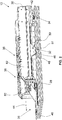
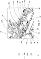
- Fig. 1 the rear view of an ambulance vehicle 10 is shown, in which an extendible receiving device 12 for an ambulance device 14 is located.
- the patient transport device 14 comprises a patient stretcher 16 and a chassis 18 which, in particular, is automatically height-adjustable and with which the patient carrier 16 can be conveniently moved and raised and lowered outside of the patient transport vehicle 10.
- the stretcher 16 is locked to the chassis 18 and can be removed from the chassis 18 in order to be used as a manually portable stretcher 16.
- the stretcher 16 has a patient transport surface 20, which has adjustable back, thigh and lower leg parts and a fixed seat part, which can be adjusted as a lying surface or, if necessary, as a chair surface.
- the receiving device 12 can be pulled out in two stages and has a base 26, which is height-adjustable mounted on the vehicle floor 22 or the loading area 24 of the ambulance vehicle 10, with a raised elongated guide housing 27 on which the guide housing 27 is guided in a longitudinally displaceable manner around three sides , wherein a receiving carriage 30, which also encompasses this on three sides, is guided in a longitudinally displaceable manner on the middle carriage 28. In this way, a doubly extendable receiving device 12 is created.
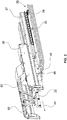
- the locking of the receiving device 12 in the ambulance vehicle 10 takes place in this embodiment by two hold-down devices 32 and also two locking locks 34, as shown in FIGS Figs. 2 and 3 is shown.
- the hold-down devices 32 and the locking locks 34 are arranged on the base 26 and hold the receiving carriage 30 in its position that has been completely retracted into the ambulance vehicle 10 (see FIG Fig. 2 ) both horizontally and laterally and vertically in position.
- the patient transport device 14 is in turn locked on the receiving carriage 30, which is for example in the Figs. 2 to 5 is indicated by locking claws 36 (see also Fig. 17 ), which cooperate with the locking hook 38 of the patient transport device 14 (indicated in, for example, the Figs. 7th and 9 ).
- the Fig. 3 shows the situation in which the center carriage 28, which is guided displaceably on the guide housing 27 of the base 26, has moved into its maximum extended position.
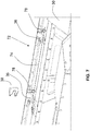
- the intermediate carriage 28 now locks by means of an automatically locking lock 52 (see FIG Fig. 5 ), which can be automatically opened (later again) by actuating / acting on a release lever, on the base 26 or on its guide housing 27.
- the receiving carriage 30 is unlocked from the state previously fixed on the intermediate carriage 28, so that the receiving carriage 30 then can be pulled out further in the pull-out direction 44.
- Fig. 5 shows the situation in which the receiving carriage 30 is shortly before its maximum extended position (loading or unloading position).
- the locking device has a for example by a gate or the like. guided pivotable control lever 56, which is provided with a roller 58 which rolls on the intermediate carriage 28 when the receiving carriage 30 move relative to the intermediate carriage 28 (see also Fig. 5 ).
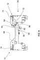
- the control lever 56 is pivotally mounted on a pivot bearing 60 of the receiving carriage 30, so it can be in the direction of arrow 62 of the Fig. 6 Starting from the position shown there, pivot to the left.
- the pivot bearing end of the control lever 56 has two protruding connecting levers 64, 66, with each of which a control lever 68, 70 is articulated, which, starting from the respective levers 64, 66, lead to both longitudinal sides 72 of the receiving carriage 30.
- the roller 58 of the control lever 56 reaches the maximum extension position of the receiving carriage 30 relative to the center carriage 28 on a link block 76, which ensures that the control lever 56 automatically in the direction of arrow 62 of the Fig. 6 is pivoted. While the locking claws 36 were previously positioned in their locking position, they are now pivoted into the open position by this control lever movement and the linkage formed by the levers 64, 66, 68, 70 and the control rods 74 (see FIG Fig. 10 ).
- the locking claws 36 release the locking hooks 38 on the ambulance transport device 14, which is no later than 95% or 90% or 80% or 70% or 60% or 50% or 40% of the starting position from the fully retracted retracted position to the fully extended Unloading and loading position of the receiving carriage 30 takes place.
- the patient transport device in the loading or unloading position (maximum extended position) of the receiving carriage 30, can either be withdrawn from the latter or, if the chassis 18 is present on the patient stretcher 16 of the patient transport device 14, by extending the chassis 18 over the stretcher 16 the receiving carriage 30 can be lifted out so that the patient transport device 14 can then be moved away from the receiving carriage 30.
- each control rod 74 a separate control lever is provided, which is provided or coupled, for example, with an axially displaceable rack and which moves this rack, for example, guided by a link.
- the rack is in toothed engagement with a pinion or gearwheel which is firmly connected to the control rod and rotates it when the rack is moved clockwise or in the opposite direction to bring the locking claws 36 into locking engagement with the locking hooks 38 or out of locking engagement with them.
- the prestressing springs 78 are designed as four leg springs, the helical section of which extends around the control rods 74 in the area of the locking claws 36 and whose protruding legs are supported on the one hand on the receiving carriage 30 and on the other hand on the locking claws 36.
- Other configurations of the pretensioning device for pretensioning the locking claws 36 and thus the locking device 54 into the locking position are of course also possible.
- the special feature of the locking device 54 is that the patient transport device 14 is not locked on the receiving carriage 30 when the receiving carriage 30 is in its loading or unloading position (extended to the maximum). Rather, the patient transport device 14 is locked on the receiving carriage 30 and thus on the receiving device 12 only after the receiving carriage 30 has left its fully extended extended position, i.e. its loading or unloading position, for example after covering a maximum of 5% or a maximum 10% or a maximum of 20% or a maximum of 30% or a maximum of 40% or a maximum of 60% of the entry path starting from the fully extended extension position to the fully retracted entry position of the receiving carriage 30.
- the patient transport device 14 is unlocked at the latest after 95% or 90% or 80% or 70% or 60% or 50% or 40% of the starting position from the fully retracted entry position to the fully extended unloading or loading position of the receiving carriage 30.
- Figs. 11 to 19 show different views of the receiving device with or without an ambulance transport device in order to illustrate the loading and unloading process.
- the intermediate carriage 28 is locked to the base 26 or to the guide housing 27 of the base 26 by means of the locking lock 52.
- a locking lock 80 on the receiving carriage 30, which can be automatically opened (later again) by actuating / acting on a release lever and by means of which the receiving carriage 30 is locked in the maximum extended position on the intermediate carriage 28.
- the roller 58 has moved onto the slide block 76 so that the locking claws 36 are in their open positions.
- the receiving carriage 30 has two arms 82 which form the longitudinal sides 72 of the receiving carriage 30.
- Each boom 82 is supported by a support structure 46 with support roller 48 on the base 26 when the receiving carriage 30 is fully retracted.
- the receiving carriage 30 has handles 84 by which the receiving carriage 30 is manually gripped when the receiving carriage 30 is extended or retracted.
- Fig. 13 shows the situation in which the patient transport device 14 rests on the fully extended receiving carriage 30 with the chassis 18 retracted.
- the castors 90 of the chassis 18 are located directly below the receiving carriage 30, that is to say above the base 26, so that the receiving carriage 30 is pushed into the ambulance vehicle 10 or pulled out of the ambulance vehicle 10.
- Fig. 13 shows the situation in which the patient transport device 14, that is to say the patient stretcher 16 and the chassis 18, are positioned on the receiving carriage 30.
- the receiving carriage 30 can also only be loaded with the stretcher 16.
- the stretcher 16 has the locking hooks 38 already mentioned above, which interact with the locking claws 36 of the locking device 54.
- the chassis 18, in turn, is locked to the stretcher 16 by, for example, an upper frame (not shown) of the chassis 18 carrying the stretcher 16 and being locked to it.
- the chassis 18 has, as for example in Figs. 14th and 15th shown, a height adjustment mechanism 92 in the form of a scissor lift with drive 94, which is supported on a lower frame 96, which in turn is provided with the running or steering rollers 90.
- Other height adjustment mechanisms for chassis 18 of patient transport device 14 can of course also be used.
- Fig. 14 the situation is shown in which the receiving device 12 or its receiving carriage 30 is in the loading or unloading position and the patient transport device 14 is located on the receiving carriage 30, the chassis 18 being partially extended or retracted.
- the chassis 18 hangs from below, so to speak, on the stretcher 16.
- the stretcher 16 is not locked on the receiving carriage 30 (see above the description of the locking device 54, which is in its unlocked position when the receiving carriage 30 is fully extended).
- the chassis 18 is now extended further (based on the situation according to FIG Fig. 14 ), then the castors 90 of the chassis 18 set finally on the ground 98 (for example roadway). If, based on this situation, the chassis 18 is extended further, its upper frame with the stretcher 16 resting on it lifts upwards from the receiving carriage 30 (see FIG Fig. 15 ). The patient transport device 14 can now be moved away from the receiving carriage 30.
- Fig. 16 again clarifies this process, where in Fig. 16 the situation is shown in which the patient transport device 14 is maneuvered to drive up or drive over the receiving carriage 30.
- Fig. 17 shows the area XVII of the Fig. 16 on a larger scale.
- the upper frame 100 of the chassis 18 is provided with locking locks (not shown) which can be unlocked by two release levers 102. For each longitudinal spar of the upper frame 100, this is provided with a release lever 102.
- a linkage that is moved by the release lever 102 can be used, for example, to open two locks arranged in the upper frame 100 per longitudinal spar.
- the stretcher has locking pins or the like (also not shown). that cooperate with the locks.
- the stretcher also has outwardly conically tapering roller elements 104 which, as will be described below, serve to center when the stretcher (in particular without chassis 18) is pushed onto the receiving tracks 86 of the boom 82. Because, for example, in Fig. 11 shown, the receiving tracks 86 are aligned upwardly sloping towards the outside, it comes with the conically tapering outward roller elements 104 on the stretcher to a centering (see Figs. 18 and 19 ).
- the above-described centering of the stretcher 16 on the arms 82 of the receiving carriage 30 is required in particular if the stretcher 16 is to be positioned on the receiving carriage 30 without the chassis 18. If, on the other hand, the stretcher 16 is on the chassis 18 or if the chassis 18 is to be positioned without the stretcher 16 on the receiving carriage 30, two guide struts 106 projecting downwards from the upper frame 100 of the chassis 18 serve as rotating sleeves are formed.
- the guide struts 106 cooperate with inner inlet edges on the receiving tracks 86, which form inner guide edges 108 on the two arms 82.
- the guide edges 108 are spaced further apart at the ends of the two arms 82 in the area of the respective handles 84 than in the adjoining section of the arms 82.
- the guide struts 106 are on the upper frame 100 of the chassis 18 above the steering wheel which is at the front during loading. or castors 90 of the chassis 18 positioned, which the maneuverability of the chassis 18 and the patient transport device 14 overall substantially facilitates, the threading of the chassis 18 when this is not due to the contact of the guide struts 106 at the level of the front castors or castors 90 is pushed exactly in alignment with the free space between the two arms 82 of the receiving carriage 30 on this, facilitate.
- the centering of the chassis 18 by means of the guide struts 106 is in the Figs. 18 and 19 illustrated. It shows Fig. 18 yet another specialty. As can be seen, the guide edges 108 are convexly curved. This means that even when the chassis 18 is rotated relative to the horizontal alignment of the receiving device or the receiving carriage 30, the guide struts 106 can still be moved into the space defined by the guide edges 108. For example, then in the situation according to Fig. 18 the chassis 18 is retracted, the chassis 18 is positioned with respect to its upper frame 100 and the stretcher 16 is automatically centered on the receiving carriage 30 or on its boom 82 (see Fig. 19 ).
- the locking lock 80 which locks the receiving carriage 30 relative to the center carriage 28, is released by means of a release lever or a release button 110 on one of the two handles 84 of the receiving carriage 30 via a Bowden cable.
- the middle carriage 28 is still locked with respect to the guide housing 27 of the base 26. If the receiving carriage 30 is now pushed in, it moves in relation to and on the middle carriage 28.
- the locking device 54 locks shortly after leaving the loading position of the receiving carriage 30, that is, it is transferred from its unlocked position to the locking position, which is expediently already after covering a maximum of half, 2/3, 1/4, 1/8 or 1 / 10 of the travel path of the receiving carriage starting from its loading position up to its fully retracted position.
- the control lever 56 rolls off the link block 76 via its roller 58. Due to the locking claws 36 preloaded into the locking position, the entire locking device 54 moves into the locking position. The control lever 56 accordingly swivels into the position shown in FIG Fig. 6 (see also the Fig. 21 ).
- the support structure 46 is located approximately in the middle of the patient transport device or the stretcher 16. In this embodiment, the support structure 46 is located essentially below the seat part of the stretcher 16. Both sides of the seat part of the stretcher 16 are located in this embodiment Fold-up side parts 115.
- two struts 116 each extend to the front and to the rear end of the patient transport device 14. Like the support structure 46, these struts 116 are part of each arm 82 of the receiving carriage 30. The struts 116 end in the area of the locking claws 36 on which the patient transport device is in locking engagement with the locking device 54 with its locking hook 38.
- the receiving carriage 30 In the event of accelerations acting vertically upward on the patient transport device 14, the receiving carriage 30 would experience a torque around its rear end located furthest in the vehicle. However, because the patient transport device 14 is held down in its center of gravity (given with a patient loaded state) by the hold-down devices 32, the torques can be absorbed. Movements of the receiving carriage 30 in the longitudinal direction are prevented by the locking locks 34. Movements of the receiving carriage 30 transversely thereto are in turn prevented by the hold-down devices 32.
- the receiving device 12 allows it to be lifted by means of a lifting mechanism 118 when the receiving carriage 30 is fully retracted into the vehicle. If an ambulance transport device 14 with a patient is then located on the receiving carriage 30, it is possible to raise this patient to a height at which he can be comfortably looked after by the paramedic or emergency doctor during the transport.
- the lifting mechanism 118 is accommodated in the guide housing 27 in a space-saving manner.
- the guide housing 27 protrudes centrally from the base 26.
- the central U-configuration of the middle carriage 28 and the receiving carriage 30 in connection with the guide housing 27 ensures a space-saving and compact design of the receiving device 12.
- the space gained in the center below the patient transport device 14 to be transported can now be advantageous for accommodating the lifting mechanism 118 be used.
- An essential reason for the fact that there is space at all in this area of the receiving device 12 is that, according to the invention, it is not the patient transport device 14 itself that is locked directly, for example, on the loading area 24 of the patient transport vehicle 10, but that it rather, it is the receiving carriage 30 which is locked to the base 26 or possibly also to the loading area 24 and the patient transport device 14 is in turn locked to the receiving carriage 30. So there are no locking elements protruding downward from the ambulance device 14 in order to be locked directly to the base 26 or the loading area 24 of the ambulance vehicle 10.
- the lifting mechanism 118 in this embodiment of the invention is characterized by a low overall height. It comprises two pivotable pivot arms 120 which are pivotably mounted in pivot bearings 124, which in turn are arranged below the base 26.
- the two pivot arms 120 are designed as angle arms which, viewed from the pivot bearing 124, extend essentially at a right angle to one another.
- the essentially horizontally aligned first partial arm 126 is supported on a console 128 on the vehicle floor 22 of the ambulance vehicle 10, while the second partial arm 130 in this exemplary embodiment interacts with a spindle drive 132, for example.
- the spindle drive 132 has a spindle 134 which interacts with spindle sleeves 136 on the partial arms 130.
- the spindle sleeve 136 moves axially on the spindle 134 and moves the arms 130 of the two pivot arms 120 towards or away from one another, so that the pivot arms 120 press around their pivot bearings 124.
- the pivot arms 120 when rotated about the pivot bearings 124, with their essentially horizontally extending arms 126 are attached to the consoles 128, as a result of which the lifting mechanism 118 is raised or lowered.
- the arms 126 of the two pivot arms 120 are rotatably mounted on the consoles 128.
- the consoles 128 themselves can be via a rail system or the like. Move transversely to the longitudinal extension of the ambulance vehicle 10.
- the receiving device 12 can thus be shifted in the lateral direction in the ambulance vehicle 10 in order to be able to provide more space on one side of the receiving device 12 for a paramedic or emergency doctor caring for a patient in the vehicle.
- a bellows 138 is used in this exemplary embodiment, which runs along the edge of the base 26 as a cover with two long sides and two transverse sides, is fastened there and mounted at its other end on the vehicle floor 22 is.
Landscapes
- Health & Medical Sciences (AREA)
- Public Health (AREA)
- Life Sciences & Earth Sciences (AREA)
- Animal Behavior & Ethology (AREA)
- General Health & Medical Sciences (AREA)
- Veterinary Medicine (AREA)
- Invalid Beds And Related Equipment (AREA)
Applications Claiming Priority (1)
| Application Number | Priority Date | Filing Date | Title |
|---|---|---|---|
| PCT/EP2019/062389 WO2020228945A1 (fr) | 2019-05-14 | 2019-05-14 | Procédé de chargement et de déchargement d'un véhicule de transport de malades |
Publications (3)
| Publication Number | Publication Date |
|---|---|
| EP3738568A1 true EP3738568A1 (fr) | 2020-11-18 |
| EP3738568C0 EP3738568C0 (fr) | 2025-01-01 |
| EP3738568B1 EP3738568B1 (fr) | 2025-01-01 |
Family
ID=66668879
Family Applications (1)
| Application Number | Title | Priority Date | Filing Date |
|---|---|---|---|
| EP20174795.3A Active EP3738568B1 (fr) | 2019-05-14 | 2020-05-14 | Procédé de déchargement d'une ambulance |
Country Status (5)
| Country | Link |
|---|---|
| EP (1) | EP3738568B1 (fr) |
| DE (5) | DE112019007314A5 (fr) |
| ES (1) | ES3017909T3 (fr) |
| PL (1) | PL3738568T3 (fr) |
| WO (1) | WO2020228945A1 (fr) |
Cited By (1)
| Publication number | Priority date | Publication date | Assignee | Title |
|---|---|---|---|---|
| US12208042B2 (en) | 2021-09-29 | 2025-01-28 | Stryker Corporation | Patient transport apparatus having an extender for a head deck section |
Families Citing this family (2)
| Publication number | Priority date | Publication date | Assignee | Title |
|---|---|---|---|---|
| WO2011041170A2 (fr) * | 2009-10-02 | 2011-04-07 | Stryker Corporation | Civière d'ambulance et système de chargement et de déchargement |
| CN117357344A (zh) * | 2023-11-15 | 2024-01-09 | 军事科学院系统工程研究院卫勤保障技术研究所 | 车载卧姿伤病员装卸承运装置 |
Citations (8)
| Publication number | Priority date | Publication date | Assignee | Title |
|---|---|---|---|---|
| GB2203999A (en) | 1987-03-11 | 1988-11-02 | Macclesfield Motor Bodies | Vehicle loading platform |
| FR2682930A1 (fr) | 1991-10-28 | 1993-04-30 | Heli Rhone Alpes | Installation sanitaire pour helicoptere notamment. |
| WO2004064698A2 (fr) | 2003-01-15 | 2004-08-05 | Stryker Corporation | Dispositif de chargement et de dechargement de civiere d'ambulance |
| WO2016007290A1 (fr) | 2014-07-08 | 2016-01-14 | Stryker Corporation | Appareil de chargement et de déchargement |
| WO2018153940A1 (fr) | 2017-02-21 | 2018-08-30 | Stollenwerk und Cie. GmbH Fabrik für Sanitätsausrüstungen | Dispositif de transport de malades |
| WO2018206834A1 (fr) | 2017-05-12 | 2018-11-15 | Kartsana, S.L. | Système d'ancrage d'une civière |
| DE102018111654A1 (de) | 2018-05-15 | 2019-11-21 | Stollenwerk und Cie. GmbH Fabrik für Sanitätsausrüstungen | Krankentransportvorrichtung, insbesondere für einen Kranken- oder Rettungstransportwagen |
| EP3613396A1 (fr) | 2018-08-20 | 2020-02-26 | Stollenwerk und Cie. GmbH Fabrik für Sanitätsausrüstungen | Dispositif de transport des malades |
-
2019
- 2019-05-14 WO PCT/EP2019/062389 patent/WO2020228945A1/fr not_active Ceased
- 2019-05-14 DE DE112019007314.1T patent/DE112019007314A5/de active Pending
-
2020
- 2020-05-14 DE DE202020102741.7U patent/DE202020102741U1/de active Active
- 2020-05-14 DE DE202020102743.3U patent/DE202020102743U1/de active Active
- 2020-05-14 ES ES20174795T patent/ES3017909T3/es active Active
- 2020-05-14 EP EP20174795.3A patent/EP3738568B1/fr active Active
- 2020-05-14 PL PL20174795.3T patent/PL3738568T3/pl unknown
- 2020-05-14 DE DE202020102738.7U patent/DE202020102738U1/de active Active
- 2020-05-14 DE DE202020102742.5U patent/DE202020102742U1/de active Active
Patent Citations (10)
| Publication number | Priority date | Publication date | Assignee | Title |
|---|---|---|---|---|
| GB2203999A (en) | 1987-03-11 | 1988-11-02 | Macclesfield Motor Bodies | Vehicle loading platform |
| FR2682930A1 (fr) | 1991-10-28 | 1993-04-30 | Heli Rhone Alpes | Installation sanitaire pour helicoptere notamment. |
| WO2004064698A2 (fr) | 2003-01-15 | 2004-08-05 | Stryker Corporation | Dispositif de chargement et de dechargement de civiere d'ambulance |
| EP2116216A2 (fr) | 2003-01-15 | 2009-11-11 | Stryker Corporation | Dispositif de chargement et de déchargement de civière d'ambulance |
| EP2138143A2 (fr) | 2003-01-15 | 2009-12-30 | Stryker Corporation a Corporation of the State of Michigan | Dispositif de chargement et de déchargement de civière d'ambulance |
| WO2016007290A1 (fr) | 2014-07-08 | 2016-01-14 | Stryker Corporation | Appareil de chargement et de déchargement |
| WO2018153940A1 (fr) | 2017-02-21 | 2018-08-30 | Stollenwerk und Cie. GmbH Fabrik für Sanitätsausrüstungen | Dispositif de transport de malades |
| WO2018206834A1 (fr) | 2017-05-12 | 2018-11-15 | Kartsana, S.L. | Système d'ancrage d'une civière |
| DE102018111654A1 (de) | 2018-05-15 | 2019-11-21 | Stollenwerk und Cie. GmbH Fabrik für Sanitätsausrüstungen | Krankentransportvorrichtung, insbesondere für einen Kranken- oder Rettungstransportwagen |
| EP3613396A1 (fr) | 2018-08-20 | 2020-02-26 | Stollenwerk und Cie. GmbH Fabrik für Sanitätsausrüstungen | Dispositif de transport des malades |
Cited By (1)
| Publication number | Priority date | Publication date | Assignee | Title |
|---|---|---|---|---|
| US12208042B2 (en) | 2021-09-29 | 2025-01-28 | Stryker Corporation | Patient transport apparatus having an extender for a head deck section |
Also Published As
| Publication number | Publication date |
|---|---|
| EP3738568C0 (fr) | 2025-01-01 |
| DE202020102742U1 (de) | 2020-08-18 |
| WO2020228945A1 (fr) | 2020-11-19 |
| DE202020102741U1 (de) | 2020-08-18 |
| ES3017909T3 (en) | 2025-05-14 |
| PL3738568T3 (pl) | 2025-06-16 |
| EP3738568B1 (fr) | 2025-01-01 |
| DE202020102738U1 (de) | 2020-08-18 |
| DE112019007314A5 (de) | 2022-03-17 |
| DE202020102743U1 (de) | 2020-08-18 |
Similar Documents
| Publication | Publication Date | Title |
|---|---|---|
| EP0311936B1 (fr) | Chariot pour un brancard | |
| DE4026120C2 (de) | Vorrichtung zum Öffnen und Schließen eines Daches eines Fahrzeugs mit offenem Dach | |
| EP3738568B1 (fr) | Procédé de déchargement d'une ambulance | |
| DE102012006385B4 (de) | Verdeckgestell für einen Planenaufbau | |
| DE3417599C2 (fr) | ||
| EP0893302A2 (fr) | Plateau de chargement extensible pour un véhicule | |
| DE102015208351A1 (de) | Baueinheit, umfassend eine Sitzeinrichtung und eine Halterung für die Sitzeinrichtung, zur Anordnung in einem Schienenfahrzeug, Verfahren zum Überführen der Sitzeinrichtung von einer Verstaustellung in eine Gebrauchsstellung sowie Schienenfahrzeug mit mindestens einer Baueinheit | |
| EP2774794B1 (fr) | Dispositif de toit coulissant de véhicule | |
| DE69707917T2 (de) | Fahrzeugausrüstung zur transferierung und befestigung eines in einen rollstuhl umwandelaren sitzes | |
| DE102012008473A1 (de) | Hubvorrichtung zur Aufnahme von Lasten, insbesondere eines Rollstuhls in einem Transportfahrzeug | |
| WO2011054581A1 (fr) | Dispositif pour recevoir un brancard | |
| DE202021003972U1 (de) | Kraftfahrzeug mit Plattformlift-System zum sicheren Ein- und Ausladen sowie zum Befördern von Transportpersonen | |
| DE102017220199B3 (de) | Ladevorrichtung, Kraftfahrzeug und Mobilitätssystem | |
| DE20219336U1 (de) | Fahrzeug | |
| DE29911783U1 (de) | Demontierbarer Fahrzeugsitz | |
| DE202021003975U1 (de) | Plattformlift-System zum sicheren Transport von Personen in einem Kraftfahrzeug sowie Kraftfahrzeug mit einem solchen Plattformlift-System | |
| DE102005047213B4 (de) | Bestattungsfahrzeug mit separat ausziehbaren Ladeboden-Bahnen | |
| AT17658U1 (de) | Fahrzeug zur Beförderung von Personen | |
| DE102005047214B4 (de) | Bestattungsfahrzeug mit unabhängig voneinander höhen- und längsbeweglichen Ladeboden-Bahnen | |
| DE102024104838A1 (de) | Spriegelanordnung für einen Fahrzeugaufbau, Fahrzeugaufbau und Nutzfahrzeug | |
| DE202024105436U1 (de) | Rampe für Transportstühle sowie Transportfahrzeug mit einer solchen Rampe | |
| DE2112329A1 (de) | Transportfahrzeug fuer Fertiggaragen u.dgl. | |
| EP4098235A1 (fr) | Système de plate-forme élévatrice destiné au transport sécurisé des personnes dans un véhicule automobile, ainsi que véhicule automobile doté d'un tel système de plate-forme élévatrice | |
| DE202020100284U1 (de) | Beladevorrichtung für ein Bestattungsfahrzeug | |
| DE202025106052U1 (de) | Rettungstransportfahrzeug oder Krankentransportfahrzeug mit einem Fahrzeugaufbau, einem separierten Stauraumfach und einem Lift-System dafür |
Legal Events
| Date | Code | Title | Description |
|---|---|---|---|
| PUAI | Public reference made under article 153(3) epc to a published international application that has entered the european phase |
Free format text: ORIGINAL CODE: 0009012 |
|
| STAA | Information on the status of an ep patent application or granted ep patent |
Free format text: STATUS: THE APPLICATION HAS BEEN PUBLISHED |
|
| AK | Designated contracting states |
Kind code of ref document: A1 Designated state(s): AL AT BE BG CH CY CZ DE DK EE ES FI FR GB GR HR HU IE IS IT LI LT LU LV MC MK MT NL NO PL PT RO RS SE SI SK SM TR |
|
| AX | Request for extension of the european patent |
Extension state: BA ME |
|
| STAA | Information on the status of an ep patent application or granted ep patent |
Free format text: STATUS: REQUEST FOR EXAMINATION WAS MADE |
|
| 17P | Request for examination filed |
Effective date: 20210507 |
|
| RBV | Designated contracting states (corrected) |
Designated state(s): AL AT BE BG CH CY CZ DE DK EE ES FI FR GB GR HR HU IE IS IT LI LT LU LV MC MK MT NL NO PL PT RO RS SE SI SK SM TR |
|
| GRAP | Despatch of communication of intention to grant a patent |
Free format text: ORIGINAL CODE: EPIDOSNIGR1 |
|
| STAA | Information on the status of an ep patent application or granted ep patent |
Free format text: STATUS: GRANT OF PATENT IS INTENDED |
|
| INTG | Intention to grant announced |
Effective date: 20240723 |
|
| GRAS | Grant fee paid |
Free format text: ORIGINAL CODE: EPIDOSNIGR3 |
|
| GRAA | (expected) grant |
Free format text: ORIGINAL CODE: 0009210 |
|
| STAA | Information on the status of an ep patent application or granted ep patent |
Free format text: STATUS: THE PATENT HAS BEEN GRANTED |
|
| AK | Designated contracting states |
Kind code of ref document: B1 Designated state(s): AL AT BE BG CH CY CZ DE DK EE ES FI FR GB GR HR HU IE IS IT LI LT LU LV MC MK MT NL NO PL PT RO RS SE SI SK SM TR |
|
| REG | Reference to a national code |
Ref country code: GB Ref legal event code: FG4D Free format text: NOT ENGLISH |
|
| REG | Reference to a national code |
Ref country code: CH Ref legal event code: EP |
|
| REG | Reference to a national code |
Ref country code: DE Ref legal event code: R096 Ref document number: 502020010081 Country of ref document: DE |
|
| REG | Reference to a national code |
Ref country code: IE Ref legal event code: FG4D Free format text: LANGUAGE OF EP DOCUMENT: GERMAN |
|
| U01 | Request for unitary effect filed |
Effective date: 20250131 |
|
| U07 | Unitary effect registered |
Designated state(s): AT BE BG DE DK EE FI FR IT LT LU LV MT NL PT RO SE SI Effective date: 20250206 |
|
| U20 | Renewal fee for the european patent with unitary effect paid |
Year of fee payment: 6 Effective date: 20250515 |
|
| PGFP | Annual fee paid to national office [announced via postgrant information from national office to epo] |
Ref country code: PL Payment date: 20250507 Year of fee payment: 6 |
|
| PGFP | Annual fee paid to national office [announced via postgrant information from national office to epo] |
Ref country code: GB Payment date: 20250522 Year of fee payment: 6 Ref country code: ES Payment date: 20250616 Year of fee payment: 6 |
|
| PG25 | Lapsed in a contracting state [announced via postgrant information from national office to epo] |
Ref country code: IS Free format text: LAPSE BECAUSE OF FAILURE TO SUBMIT A TRANSLATION OF THE DESCRIPTION OR TO PAY THE FEE WITHIN THE PRESCRIBED TIME-LIMIT Effective date: 20250501 |
|
| PGFP | Annual fee paid to national office [announced via postgrant information from national office to epo] |
Ref country code: NO Payment date: 20250520 Year of fee payment: 6 |
|
| PG25 | Lapsed in a contracting state [announced via postgrant information from national office to epo] |
Ref country code: HR Free format text: LAPSE BECAUSE OF FAILURE TO SUBMIT A TRANSLATION OF THE DESCRIPTION OR TO PAY THE FEE WITHIN THE PRESCRIBED TIME-LIMIT Effective date: 20250101 |
|
| PG25 | Lapsed in a contracting state [announced via postgrant information from national office to epo] |
Ref country code: GR Free format text: LAPSE BECAUSE OF FAILURE TO SUBMIT A TRANSLATION OF THE DESCRIPTION OR TO PAY THE FEE WITHIN THE PRESCRIBED TIME-LIMIT Effective date: 20250402 |
|
| PGFP | Annual fee paid to national office [announced via postgrant information from national office to epo] |
Ref country code: CH Payment date: 20250601 Year of fee payment: 6 |
|
| PGFP | Annual fee paid to national office [announced via postgrant information from national office to epo] |
Ref country code: CZ Payment date: 20250424 Year of fee payment: 6 |
|
| PGFP | Annual fee paid to national office [announced via postgrant information from national office to epo] |
Ref country code: IE Payment date: 20250522 Year of fee payment: 6 |
|
| PG25 | Lapsed in a contracting state [announced via postgrant information from national office to epo] |
Ref country code: SM Free format text: LAPSE BECAUSE OF FAILURE TO SUBMIT A TRANSLATION OF THE DESCRIPTION OR TO PAY THE FEE WITHIN THE PRESCRIBED TIME-LIMIT Effective date: 20250101 |
|
| PG25 | Lapsed in a contracting state [announced via postgrant information from national office to epo] |
Ref country code: SK Free format text: LAPSE BECAUSE OF FAILURE TO SUBMIT A TRANSLATION OF THE DESCRIPTION OR TO PAY THE FEE WITHIN THE PRESCRIBED TIME-LIMIT Effective date: 20250101 |
|
| PLBE | No opposition filed within time limit |
Free format text: ORIGINAL CODE: 0009261 |
|
| STAA | Information on the status of an ep patent application or granted ep patent |
Free format text: STATUS: NO OPPOSITION FILED WITHIN TIME LIMIT |
|
| 26N | No opposition filed |
Effective date: 20251002 |
|
| PG25 | Lapsed in a contracting state [announced via postgrant information from national office to epo] |
Ref country code: MC Free format text: LAPSE BECAUSE OF FAILURE TO SUBMIT A TRANSLATION OF THE DESCRIPTION OR TO PAY THE FEE WITHIN THE PRESCRIBED TIME-LIMIT Effective date: 20250101 |