EP3738568B1 - Procédé de déchargement d'une ambulance - Google Patents
Procédé de déchargement d'une ambulance Download PDFInfo
- Publication number
- EP3738568B1 EP3738568B1 EP20174795.3A EP20174795A EP3738568B1 EP 3738568 B1 EP3738568 B1 EP 3738568B1 EP 20174795 A EP20174795 A EP 20174795A EP 3738568 B1 EP3738568 B1 EP 3738568B1
- Authority
- EP
- European Patent Office
- Prior art keywords
- receiving
- receiving slide
- locking
- patient transport
- carriage
- Prior art date
- Legal status (The legal status is an assumption and is not a legal conclusion. Google has not performed a legal analysis and makes no representation as to the accuracy of the status listed.)
- Active
Links
Images


Classifications
-
- A—HUMAN NECESSITIES
- A61—MEDICAL OR VETERINARY SCIENCE; HYGIENE
- A61G—TRANSPORT, PERSONAL CONVEYANCES, OR ACCOMMODATION SPECIALLY ADAPTED FOR PATIENTS OR DISABLED PERSONS; OPERATING TABLES OR CHAIRS; CHAIRS FOR DENTISTRY; FUNERAL DEVICES
- A61G3/00—Ambulance aspects of vehicles; Vehicles with special provisions for transporting patients or disabled persons, or their personal conveyances, e.g. for facilitating access of, or for loading, wheelchairs
- A61G3/02—Loading or unloading personal conveyances; Facilitating access of patients or disabled persons to, or exit from, vehicles
- A61G3/0218—Loading or unloading stretchers
- A61G3/0245—Loading or unloading stretchers by translating the support
-
- A—HUMAN NECESSITIES
- A61—MEDICAL OR VETERINARY SCIENCE; HYGIENE
- A61G—TRANSPORT, PERSONAL CONVEYANCES, OR ACCOMMODATION SPECIALLY ADAPTED FOR PATIENTS OR DISABLED PERSONS; OPERATING TABLES OR CHAIRS; CHAIRS FOR DENTISTRY; FUNERAL DEVICES
- A61G3/00—Ambulance aspects of vehicles; Vehicles with special provisions for transporting patients or disabled persons, or their personal conveyances, e.g. for facilitating access of, or for loading, wheelchairs
- A61G3/02—Loading or unloading personal conveyances; Facilitating access of patients or disabled persons to, or exit from, vehicles
- A61G3/0218—Loading or unloading stretchers
- A61G3/0254—Loading or unloading stretchers by moving the stretcher on a horizontal path, e.g. sliding or rolling
-
- A—HUMAN NECESSITIES
- A61—MEDICAL OR VETERINARY SCIENCE; HYGIENE
- A61G—TRANSPORT, PERSONAL CONVEYANCES, OR ACCOMMODATION SPECIALLY ADAPTED FOR PATIENTS OR DISABLED PERSONS; OPERATING TABLES OR CHAIRS; CHAIRS FOR DENTISTRY; FUNERAL DEVICES
- A61G3/00—Ambulance aspects of vehicles; Vehicles with special provisions for transporting patients or disabled persons, or their personal conveyances, e.g. for facilitating access of, or for loading, wheelchairs
- A61G3/02—Loading or unloading personal conveyances; Facilitating access of patients or disabled persons to, or exit from, vehicles
- A61G3/0218—Loading or unloading stretchers
- A61G3/0272—Loading or unloading stretchers by support protruding from the vehicle
Definitions
- the invention relates to a method for unloading a patient transport device from a vehicle, according to claim 1.
- a loading and unloading table for a stretcher is known in which the stretcher is already locked on an extendable table when the table is in its fully extended loading or unloading position, or is still locked when the previously retracted table is fully extended to its loading or unloading position.
- FR-A-2 682 930 A loading and unloading table for stretchers is described, in which the stretcher is pushed onto the table while it is swung out from the side of the vehicle and the table is then swung into the vehicle. The method of securing the stretcher to the table and the time at which this takes place when loading the table are not described.
- the object of the invention is to provide improved methods for handling a patient transport device when loading and unloading a patient transport vehicle.
- the locking device for locking the patient transport device to the receiving carriage of the receiving device is automatically transferred from the locking position, in which the locking device is located during the extension of the receiving carriage, to the unlocking position when the receiving carriage assumes its unloading position.
- the receiving carriage In this unloading position, the receiving carriage is also automatically locked, which occurs, for example, at the latest after 95% or 90% or 80% or 70% or 60% or 50% or 40% of the travel path traveled from the fully retracted retraction position to the fully extended unloading or loading position of the receiving carriage.
- the receiving carriage projects rearwards over the loading area of the vehicle.
- the unloading position when unloading the patient transport device is identical to the loading position of the receiving carriage when it is loaded with a patient transport device, as described in detail in connection with a loading procedure below.
- the locking device is locked in its locking position when the receiving carriage is fully retracted and that this locking is released after or when the receiving carriage leaves the fully retracted position when the receiving carriage is extended.
- the fully retracted position i.e. in the starting position of the receiving carriage for unloading the patient transport device from the vehicle, the locking device is locked in its locking position. This locking is then released when the receiving carriage is extended, for example when the receiving carriage has left its fully retracted position.
- the step of unloading the patient transport device from the receiving carriage comprises the step of pulling the patient transport device off the receiving carriage.
- the patient transport device comprises a manually portable stretcher having a patient transport surface without a chassis and in particular without a height-adjustable chassis
- the step of unloading the patient transport device from the receiving carriage comprises the step of manually unloading the stretcher from the receiving carriage and the step of unlocking the patient transport device from the receiving carriage and the step of unlocking the stretcher from the receiving carriage.
- the device In the two previously described unloading processes of the patient transport device, the device remains directly or indirectly locked to the receiving carriage while it is being extended until the receiving carriage has reached its unloading position. In this unloading position, the locking device opens so that the patient transport device is either pulled off the receiving carriage or lifted above the receiving carriage in order to then be moved away, which, however, conveniently requires a height-adjustable chassis for the patient transport device.
- the step of unlocking the patient transport device from the receiving carriage comprises the step of unlocking the retracted chassis from the receiving carriage, wherein it is optionally provided that the retracted chassis rests in the fully retracted retracted position of the receiving carriage in the vehicle on the loading area of the vehicle or, if present, on a base of the receiving device fastened to the loading area of the vehicle.
- Another patient transport device that can be used according to the invention can comprise a manually portable stretcher provided with a patient transport surface, which can be positioned on a height-adjustable and in particular automatically height-adjustable chassis and can be locked to the chassis and unlocked from the chassis.
- the receiving device has a base mounted on the loading area of the vehicle, on which the receiving carriage is guided so as to be movable between its fully retracted retraction position and its loading position, wherein the receiving carriage is locked to the base and/or to the loading area of the vehicle in its fully retracted retraction position.
- the receiving device has a base that can be mounted on the loading area of the vehicle and a central carriage that is guided to extend and retract on this base, on which the receiving carriage is guided to extend and retract, wherein the receiving carriage is automatically locked to the central carriage in its maximum extended position relative to the central carriage and the central carriage is automatically locked to the base and/or the loading area of the vehicle in its maximum extended position relative to the base.
- the step of extending the receiving carriage together with the middle carriage locked to the receiving carriage to the maximum extended position of the middle carriage relative to the base or the step of extending the receiving carriage on the middle carriage to the maximum extended position of the receiving carriage relative to the middle carriage can include the step of releasing the locking device in its locked position after or at the start of the extension.
- the step of extending the receiving carriage on the middle carriage to the maximum extension position of the receiving carriage relative to the middle carriage can expediently comprise the step of automatically transferring the locking device from the locking position to the unlocking position for the purpose of unlocking the patient transport device from the receiving carriage and the step of removing the locking of the locking device in its unlocking position at the latest before or when the maximum extension position of the receiving carriage relative to the middle carriage is reached, or the step of extending the receiving carriage on the middle carriage to the maximum extension position of the receiving carriage relative to the middle carriage can comprise the step of automatically transferring the locking device from the locking position to the unlocking position for the purpose of unlocking the patient transport device on the receiving carriage and the locking of the locking device in the unlocking position at the latest before or when the fully extended (loading and) unloading position of the recording carriage is lifted.
- the extension of the receiving carriage relative to the middle carriage locked to the base up to the maximum extension position of the receiving carriage or the step of extending the middle carriage at the base up to the maximum extension position of the middle carriage relative to the base to assume the unloading position of the receiving carriage comprises the step of releasing the locking device in its locking position after or at the start of the extension.
- a further variant is directed to the step of unlocking the patient transport device from the receiving carriage comprising the step of unlocking a stretcher of the patient transport device on the receiving carriage.
- the locking device has a guided, in particular guide-guided control lever, which is kinematically coupled via a rod to at least one locking element movably arranged on the receiving carriage and preferably to two locking elements movably arranged on the receiving carriage on each long side of the patient transport device.
- the control lever is movable between an unlocking position in which the at least one locking element is disengaged from a counter-locking element of the patient transport device assigned to it, and a locking position in which the at least one locking element is in locking engagement with the counter-locking element of the patient transport device assigned to it.
- the control lever is forcibly moved from its locking position when the receiving carriage is not in its unloading position to its unlocking position during the extension of the receiving carriage, at the latest when the receiving carriage is in the loading position.
- control lever is blocked in the locking position at the latest when the receiving carriage is in the fully retracted position.
- control lever and/or the rod and/or the at least one locking element and/or each locking element is spring-loaded in the direction of the respective locking position to be assumed in the locking state of the locking device, specifically for automatically assuming the respective locking position after removing a potential blockage when the at least one locking element interacts with the counter-locking element of the patient transport device assigned to it.
- two control rods with locking claws can be rotated forwards and backwards by means of the at least one control lever and the linkage.
- the linkage has two racks, each of which is in meshing engagement with a gear on another of the two control rods.
- each control lever with rod is provided and that each control lever with rod is operatively connected to a control rod having locking claws for turning the respective control rod forwards and backwards.
- the receiving device has a base which can be mounted on the loading area of the vehicle and has a raised central region, on both sides of which the receiving carriage extends and above which the patient transport device is located in the fully retracted retraction position of the receiving carriage, wherein the base has, below its central region, a lifting lever mechanism with two automatically pivotable pivot arms which, in a lowest position of the lifting lever mechanism, lie flat and inclined, form a first acute angle with the loading area of the vehicle and in a highest position of the lifting lever mechanism, lying at an angle, form a second acute angle with the loading area of the vehicle that is larger than the first acute angle, and wherein the pivot arms are each pivotally mounted on brackets that are mounted on the loading area of the vehicle.
- the consoles or the lifting mechanism itself are arranged on the loading area of the vehicle so that they can be moved in an orthogonal direction to the longitudinal axis of the vehicle and are fixed in a moving position. This makes it possible to create more space in the vehicle on one side of the device if necessary (e.g. for the care of a patient).
- the maneuvering of the patient transport device for transferring the patient transport device into a position above the receiving carriage includes the step of centering the patient transport device relative to the receiving carriage by means of guide edges of a centering opening of the receiving carriage that are movable along, guide struts protruding from the patient transport device.
- the guide struts and the guide edges are rounded and/or curved at their respective contacting sections.
- the maneuvering of the patient transport device for transferring the patient transport device to a position above the receiving carriage away from the receiving carriage comprises the step of centering the patient transport device relative to the receiving carriage by means of sliding or roller elements of the patient transport device that can be moved and/or displaced on tracks of the receiving carriage, wherein each track is designed to project obliquely or is designed with an obliquely projecting section.
- Each sliding or roller element is expediently designed to taper obliquely at its end facing the relevant longitudinal side of the patient transport device, the inclination of the incline of the track being substantially equal to the inclination of the taper of the sliding or roller elements.
- the tracks are advantageously arranged on both sides of the centering opening of the receiving carriage, wherein the obliquely extending sections of the tracks are arranged facing away from the associated guide edge or wherein the tracks extend obliquely facing away from the respective associated guide edge.
- the receiving carriage can be locked and, if necessary, held down against inadvertent movement in both directions along the central axis of the receiving carriage at its end furthest inside the chassis in the fully retracted retraction position and, if applicable, at the end opposite this end on the loading area of the vehicle or, if available, on a base of the receiving device attached to the loading area of the vehicle and can be released when or after the receiving carriage leaves the fully retracted retraction position.
- the patient transport device is expediently locked to the receiving carriage in the fully retracted position thereof exclusively by means of the locking device (in particular against vertically upward forces) and in this state is fixed in a stable position by locking the receiving carriage to the vehicle, in particular to its loading area or, if present, to a base of the receiving device attached to the loading area, optionally with the interposition of a middle carriage between the receiving carriage and the base, whereby the middle carriage and the receiving carriage are locked together, whereby this stable position fixation is released when or after leaving the fully retracted position of the receiving carriage.
- the stretcher is locked to the chassis and the stretcher is locked to the receiving carriage in the fully retracted retracted position, wherein the chassis is arranged below the stretcher and hanging within the receiving carriage or supported on it.
- a receiving device loading and/or unloading platform of the vehicle is first extended manually or automatically, so that a receiving carriage of the receiving device, which serves to receive the patient transport device outside the vehicle, projects backwards over the loading edge of the vehicle.
- the receiving carriage is secured in its fully retracted retracted position in the vehicle against horizontal movements (in or opposite to the direction of travel and transversely to it) and vertical movements.
- the patient transport device is located on the receiving carriage inside the vehicle, it is locked to it, again in the horizontal (forwards and backwards and to the side) and in the vertical direction.
- the patient transport device expediently has no direct locking to the vehicle (for example to the loading area of the vehicle).
- the patient transport device In the loading position of the receiving carriage, it is, as already mentioned above, outside the vehicle. In the loading position, the patient transport device is pushed onto the receiving carriage or placed on the receiving carriage from above. When the patient transport device is in its correct position on the receiving carriage, it is not yet locked to the receiving carriage. This locking only takes place when the receiving carriage is retracted (manually or automatically) after it has left its loading position, and is preferably already done after the receiving carriage has travelled a maximum of half, a maximum of 2/3, a maximum of 1/4, a maximum of 1/8 or a maximum of 1/10 of the travel path from its loading position to its fully retracted position.
- the special feature of the invention is that the patient transport device, which can be a stretcher without a chassis, a stretcher with a chassis from which the stretcher can be removed, or a chassis with a lying and/or sitting surface permanently arranged on it, is locked to the receiving carriage in the fully retracted position of the receiving carriage and not directly to the vehicle.
- the receiving device is designed to be easily extendable.
- the receiving carriage is located, for example, on a base of the receiving device, which is fixed in the vehicle.
- a lifting mechanism can be located between the base and the loading area of the vehicle, for example to be able to lift a patient transported on the patient transport device in the vehicle to a treatment height that is comfortable for the paramedics.
- Such a lifting mechanism can also be an integral part of the receiving device.
- the above-mentioned step f) additionally comprises the step of locking the locking device in its locking position at the latest before or when the receiving carriage reaches the fully retracted position.
- the step of moving the patient transport device onto the receiving carriage includes the step of pushing the patient transport device onto the receiving carriage.
- the patient transport device is pushed manually or automatically onto the receiving carriage in its loading position.
- This variant is typically used when the patient transport device is designed as a stretcher or, in the case of a patient transport device which has a combination of chassis and removable stretcher, for whatever reason only the stretcher is to be used for patient transport.
- the patient transport device has a manually portable stretcher with a patient transport surface without a chassis and in particular without a height-adjustable chassis and that the step of moving the patient transport device onto the receiving carriage comprises the step of manually moving the stretcher onto the receiving carriage and the step of locking the patient transport device to the receiving carriage comprises the step of locking the stretcher to the receiving carriage.
- the chassis which is particularly height-adjustable, is not yet locked in the loading position of the extended support carriage when the patient transport device is resting on the support carriage in the correct position.
- the above-mentioned step g) of locking the patient transport device to the receiving carriage includes the step of locking the retracted chassis to the receiving carriage, wherein it is optionally provided that the retracted chassis rests on the loading area of the vehicle or, if present, on a base of the receiving device attached to the loading area of the vehicle in the fully retracted retraction position of the receiving carriage in the vehicle.
- the chassis locks onto the receiving carriage when the receiving carriage has left its loading position when driving into the vehicle.
- either the stretcher or the chassis can be locked to the carriage. If the stretcher is locked to the carriage, the chassis in its retracted position (lowest height position) "hangs" from below the stretcher when the stretcher is resting on the carriage. The stretcher is then locked to the carriage (in its fully retracted retraction position or when or after leaving the loading position). However, the stretcher can also be locked to the carriage by means of the chassis. The stretcher is typically locked to the chassis when connected to the chassis. The chassis is in turn locked to the carriage so that all components are secured against three-dimensional movement during transport (the carriage is in turn locked in the vehicle).
- the receiving device has a base which can be mounted on the loading area of the vehicle and on which the receiving carriage is guided so as to be movable between its fully retracted retraction position and its loading position, wherein the receiving carriage is locked to the base and/or to the loading area of the vehicle in its fully retracted retraction position.
- the receiving device can have a base that can be mounted on the loading area of the vehicle and a central carriage that can be extended and retracted on this base, on which the receiving carriage is guided so that it can be extended and retracted, wherein the receiving carriage is automatically locked to the central carriage in its maximum extended position relative to the central carriage and the central carriage is automatically locked to the base and/or the loading area of the vehicle in its maximum extended position relative to the base.
- the receiving device is designed as a device that can be extended twice, with the receiving carriage being guided so that it can move on a central carriage and the central carriage being guided so that it can move on a base that is itself mounted in the vehicle (if necessary by means of a lifting device or a lifting mechanism).
- the receiving carriage is pulled out together with the central carriage to which the receiving carriage is locked when it is extended.
- the central carriage expediently locks automatically to the base, while the locking between the receiving carriage and central carriage is preferably released automatically, so that the receiving carriage is then pulled out relative to the central carriage when it is extended further until the receiving carriage has reached its loading position.
- the receiving carriage has a locking device for the patient transport device.
- This locking device is either in a locking position or in an unlocking position.
- the unlocking position is determined by the locking device when the receiving carriage is in its loading position.
- the locking device is preferably controlled mechanically or electronically/electrically. It is important that the locking device is in its unlocking position when the patient transport device is moved onto the receiving carriage or placed down from above. If the receiving carriage is now retracted (manually or automatically), the locking device is automatically moved from its unlocking position to the locking position. This can, for example, take place very soon after leaving the loading position.
- This fully retracted position is the position of the receiving carriage or the entire receiving device in which the receiving carriage or the receiving device is located during transport in the vehicle.
- the locking device is therefore locked in the locking position, which means that this locking occurs when the receiving carriage has reached its maximum retracted position relative to the middle carriage or the middle carriage together with the receiving carriage completely pushed onto it has reached its maximum retracted position relative to the base.
- the receiving device has a base that can be mounted on the loading area of the vehicle and a central carriage that is guided to extend and retract on this base, on which the receiving carriage is guided to extend and retract, wherein the receiving carriage is automatically locked to the central carriage in its maximum extended position relative to the central carriage and the central carriage is automatically locked to the base and/or the loading area of the vehicle in its maximum extended position relative to the base.
- the extension movement of the receiving carriage in the case of a double-extendable receiving device takes place in that the receiving carriage is first extended relative to the middle carriage locked to the base, up to the maximum extension position, in which the receiving carriage is preferably automatically locked to the middle carriage and the lock between the middle carriage and the base is released, so that when the receiving carriage is extended further, the middle carriage moves relative to the base until the middle carriage assumes its maximum extension position with respect to the base.
- the locking device is automatically locked when the receiving carriage is in its maximum retracted position relative to the middle carriage or the middle carriage is in its maximum retracted position (with the receiving carriage fully pushed open) relative to the base.
- step of locking the patient transport device to the receiving carriage includes the step of locking a stretcher of the patient transport device on the receiving carriage.
- the locking device is mechanically or electrically controlled in order to be able to be moved from its locking position to the unlocking position and vice versa.
- the mechanical control is expediently carried out via a control lever, for example guided by a slotted link, which is preferably arranged on the receiving carriage and which is kinematically coupled via a rod to at least one locking element movably arranged on the receiving carriage and preferably to two locking elements movably arranged on the receiving carriage per long side of the patient transport device, wherein the control lever is movable between an unlocking position in which the at least one locking element is in an unlocking position in which the at least one locking element is out of engagement with a counter-locking element of the patient transport device assigned to it, and a locking position in which the at least one locking element is in locking engagement with the counter-locking element of the patient transport device assigned to it, wherein the above-mentioned step f) comprises the step of transferring the control lever from its unlocking position, which is forcibly assumed in the loading position of
- step g) includes the step of locking the control lever in its locking position at the latest when the receiving carriage is in its fully retracted position.
- the swivelling or similar mobility of the control lever is blocked when the receiving carriage is in its fully retracted position, so that the control lever can no longer be adjusted due to vibrations or similar.
- the control lever is in its locking position and thus also the locking device is in its locking position.
- control lever and/or the rod and/or the at least one locking element and/or each locking element is spring-loaded in the direction of the respective locking position to be assumed in the locking state of the locking device, specifically for automatically assuming the respective locking position after removing a potential blockage when the at least one locking element interacts with the counter-locking element of the patient transport device assigned to it.
- the locking device is spring-loaded in its locking position.
- the control lever is forcibly controlled when leaving or shortly after leaving the loading position of the receiving carriage, namely from the unlocking position to the locking position.
- the locking elements or the at least one locking element are operatively connected to counter-locking elements or at least one counter-locking element on the patient transport device.
- the locking elements are designed as holding claws or holding eyes that are moved via hooks on the stretcher in the locking position of the locking device.
- the locking elements of the locking device are preferably pivoted around an axis that is parallel to the extension and retraction direction of the receiving device.
- the pivoting could just as easily take place around a pivot axis that runs transversely to the axis mentioned above.
- This variant has the advantage, however, that the locking elements in their unlocked position clear the path that is required when sliding the stretcher onto the receiving carriage.
- the spring preload of the locking device for the automatic subsequent assumption of the locking position of the locking device has the advantage that if, for whatever reason, the locking elements of the locking device do not connect with the counter-locking elements of the patient transport device (do not interact with them), subsequent hooking occurs automatically when the blockage between the locking element and the counter-locking element is removed.
- a belt of the patient restraint system typically found in patient transport devices is located between the locking element of the locking device and the counter-locking element of the patient transport device. If the belt is then moved out between the two elements, the locking device automatically snaps into place and is moved into its locking position.
- An example of such a patient restraint system is in DE-A-10 2018 111 654 described, the content of which is hereby incorporated by reference into the subject matter of the present application.
- the patient transport device can be centered when it is positioned above the receiving carriage.
- This is expediently done by maneuvering the patient transport device to transfer the patient transport device to a position above the receiving carriage comprising the step of centering the patient transport device relative to the receiving carriage by means of guide struts that can be moved along the guide edges of a centering opening of the receiving carriage and that protrude from the patient transport device.
- the guide struts protrude either from the stretcher or, if present, from its chassis.
- the guide struts should essentially be aligned with the front steering or running rollers of the chassis when the receiving carriage is loaded with the patient transport device, i.e. should essentially be located vertically above these steering or running rollers.
- the patient transport device with the chassis is centered essentially at the height of the front steering rollers. This makes maneuvering the mobile patient transport device easier. crucial when positioning above the recording carriage.
- the guide struts and the guide edges are expediently rounded and/or curved at the sections where they touch each other.
- the guide struts can be designed as vertically aligned rollers and the guide edges as horizontally aligned rounded strips.
- the advantage of the rounding of the guide edges on the support carriage in particular is that the patient transport device can be pushed onto the support carriage using the centering guide struts even if, for whatever reason, the patient transport device and the vehicle are slightly twisted relative to each other when viewed in the direction of travel (for example due to a sideways sloping surface behind the vehicle, which itself is standing on a surface oriented in the opposite direction to this).
- the latter has a substantially U-shape when viewed from above, i.e. is provided with a recess that is open to the rear.
- the longitudinal edges of the recess are then designed as preferably rounded guide edges. Adjacent to the guide edges there are tracks on the receiving carriage on which sliding or roller elements of the patient transport device can be moved or displaced.
- the transfer of the patient transport device to a position above the receiving carriage includes the step of centering the patient transport device relative to the receiving carriage by means of sliding or roller elements of the patient transport device that can be moved and/or displaced on tracks of the receiving carriage, wherein each track is designed to protrude obliquely or is designed with an obliquely protruding section.
- each sliding or roller element is designed to taper obliquely at its end facing the relevant longitudinal side of the patient transport device, the inclination of the incline of the track being substantially equal to the inclination of the taper of the sliding or roller elements.
- the tracks are arranged on both sides of the centering opening of the receiving carriage and that the obliquely projecting sections of the tracks are arranged facing away from the associated guide edge or that the tracks run obliquely projecting away from the respective associated guide edge.
- the receiving device can be provided with a lifting mechanism in order to be able to lift the receiving carriage inside the vehicle, which is particularly advantageous if the patient has to be treated during transport in the ambulance.
- the receiving device has a base that can be mounted on the loading area of the vehicle and has a raised central area, on both sides of which the receiving carriage extends and above which the ambulance device is located in the fully retracted retraction position of the receiving carriage, wherein the base has a lifting lever mechanism below its central area with two automatically pivoting pivot arms, which, when the lifting lever mechanism is in a lowest position and lying flat and inclined, form a first acute angle with the loading area of the vehicle and, when the lifting lever mechanism is in a highest position and lying inclined, form a larger angle than the first acute angle.
- the swivel arms are each pivotably mounted on brackets which are mounted on the loading area of the vehicle. Because, according to the invention, there is no need to secure the patient transport device to the vehicle loading area or to a base attached to it, the central area below the patient transport device is free when the patient transport device is on the receiving device. This free space can then preferably be used for the arrangement of a lifting mechanism (via levers, hydraulic cylinders, spindle drives or the like).
- the lifting lever mechanism described here has the advantage that it is flat, and this is true in its lowest position.
- the lifting lever mechanism or another lifting mechanism for the support device is conveniently covered on all sides by a panel that is independently adjustable in height.
- a panel that is independently adjustable in height.
- panel frames that can be moved against each other, for example, one of which is fixed and protrudes on the loading area of the vehicle or the base of the support device, while the other is arranged on the height-adjustable element of the support device. In the lowest position of the lifting mechanism, these two panels overlap to the maximum, while the degree of overlap is less when the lifting mechanism is raised.
- a triple panel frame panel or a general multiple panel frame panel it is advantageous if the panel is implemented using a circumferential bellows.
- consoles or the lifting mechanism are arranged on the loading area of the vehicle so that they can be moved in a direction orthogonal to the longitudinal axis of the vehicle and are fixed in a moving position.
- the patient transport device is locked to the receiving device, while the receiving device itself is locked in the vehicle.
- the patient transport device is locked to the receiving carriage of the receiving device on both sides of the center of gravity of the patient transport device when there is a patient on it. This is usually the case in the area of the patient's pelvis.
- the patient transport device is therefore locked to the receiving carriage.
- the receiving carriage expediently has sliding or roller elements by means of which it can rest and be moved on the loading area of a base of the receiving device when it is moved within the vehicle.
- These additional "support points" of the receiving carriage which is also guided and held on the receiving device via movable guide devices provided with rollers or similar rolling elements, are located essentially at the height of the center of gravity of the patient transport device when a patient is on it.
- the patient transport device is now locked to the receiving carriage on both sides of the patient, in front of and behind the aforementioned support points of the receiving carriage, viewed in the direction of travel of the vehicle.
- Each side of the receiving carriage is stiffened in the area of its support point, namely by stiffening struts which essentially run from the support point to each of the two locking points provided for each side of the receiving carriage for the patient transport device.
- This means that the force is now introduced from the possibly loaded patient transport device from its locking points with the support carriage via the stiffening struts to the support points of the support carriage on the loading area or on the base.
- the support carriage is in turn locked to the loading area or on the base when the support carriage is in its fully retracted position in the vehicle.
- the receiving carriage can be locked at both of its ends or at least at one of its two ends and in particular at the end furthest inside the vehicle in the fully retracted position to the loading area of the vehicle or to the base (if present) of the receiving device.
- the receiving carriage is additionally locked against unwanted movements in the retraction and extension direction of the receiving carriage and, if necessary, is additionally held down at its end furthest in the chassis in the fully retracted retraction position and, if applicable, at the end opposite this on the loading area of the vehicle or, if available, on a base of the receiving device attached to the loading area of the vehicle.
- the patient transport device is locked to the receiving carriage in the fully retracted position thereof exclusively by means of the locking device and is fixed in a stable position in this state by locking the receiving carriage to the vehicle, in particular to its loading area or, if present, to a base of the receiving device attached to the loading area and if necessary by interposing a middle carriage between the receiving carriage and the base, wherein the middle carriage and the receiving carriage are locked together.
- the receiving device or its receiving carriage When viewing the receiving device in or opposite to the direction of travel of the vehicle, i.e. when viewing the receiving device in or opposite to the respective direction of displacement of the receiving carriage on the receiving device, the receiving device or its receiving carriage essentially has a U-shape, whereby this U-shape more or less encloses the base of the receiving device on the sides and at the top. If the receiving device also has a middle carriage in addition to the base, this is located between the receiving carriage and the base in the direction described above, and therefore also has a U-shape. The middle zone left free by the receiving carriage and, if present, the middle carriage due to the respective U-shape can be used for a lifting mechanism (see above).
- the patient transport device does not have a locking mechanism that interacts directly with the loading area of the vehicle or directly with a base of the receiving device that is attached to the loading area of the vehicle, if present, when the receiving carriage is in its fully retracted position.
- the stretcher is locked to the chassis during the transport of a patient and is locked to the receiving carriage in the fully retracted retracted position, the chassis being arranged below the stretcher and hanging within the receiving carriage or resting on it.
- steps a) and b) are not necessary if the patient transport device has already been unloaded from the vehicle before loading the vehicle and the receiving carriage is therefore already in its loading position.
- snap locks are preferably suitable for purely mechanical locking.
- One or more locks are pre-tensioned in an open position so that when a locking pin is inserted into the opening, they are automatically moved into the locking position when the locking pin comes into contact with a trigger element or one of the snap locks.
- the locks are pre-tensioned in the open position for this purpose.
- the snap lock is opened from its closed position by moving a release lever, which moves the snap lock(s) back into the open position, in which the lock(s) are then automatically held again. Snap locks of this type are offered in various versions by the US company Southco.
- a control signal can be applied to an electromechanically closing and opening lock via limit switches, for example.
- the extension and retraction movements of the various components of the receiving device can also have additional drives.
- the extension and retraction movements of the support device can generally be carried out either manually or automatically, or fully automatically.
- Electrical plug-in, slider or contact arrangements can be provided for any necessary supply of the individual components of the patient transport device, i.e. the stretcher and/or the chassis, and the support device with electrical energy from the on-board network of the patient transport vehicle.
- An example of an electrical contact created by both pushing and setting down the stretcher on the chassis or the stretcher or the chassis on the support device is described in the German utility model application 20 2020 102 715.8, filed on May 14, 2020 , the content of which is hereby incorporated by reference into the subject matter of the present application.
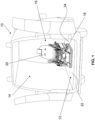
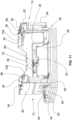
- Fig. 1 the rear view of a patient transport vehicle 10 is shown, in which there is an extendable receiving device 12 for a patient transport device 14.
- the patient transport device 14 comprises a stretcher 16 and a chassis 18, which is in particular automatically height-adjustable and with which the stretcher 16 can be easily moved and raised and lowered outside the patient transport vehicle 10.
- the stretcher 16 is locked to the chassis 18 and can be removed from the chassis 18 in order to be used as a manually portable stretcher 16.
- the stretcher 16 has a patient transport surface 20, which has adjustable back, thigh and lower leg parts and a fixed seat part, which can be adjusted as a lying surface or, if necessary, as a chair surface.
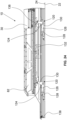
- the receiving device 12 can be adjusted in two stages and has a base 26, which is mounted on the vehicle floor 22 or the loading area 24 of the ambulance vehicle 10 so as to be height-adjustable, with a raised, elongated guide housing 27, on which a central carriage 28, which surrounds the guide housing 27 on three sides, is guided so as to be longitudinally displaceable, with a receiving carriage 30, which also surrounds the central carriage 28 on three sides, being guided so as to be longitudinally displaceable. In this way, a receiving device 12 which can be extended twice is created.
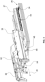
- the locking of the receiving device 12 in the ambulance vehicle 10 is carried out by two hold-down devices 32 and also two locking locks 34 in this embodiment, as is shown in the Fign. 2 and 3
- the hold-down devices 32 and the locking locks 34 are arranged on the base 26 and hold the receiving carriage 30 in its fully retracted position in the ambulance 10 (see Fig. 2 ) both horizontally and laterally and vertically into position.
- the patient transport device 14 is in turn locked to the receiving carriage 30, which is for example in the Figs. 2 to 5 indicated by locking claws 36 (see also Fig. 17 ), which interact with locking hooks 38 of the patient transport device 14 (indicated, for example, in the Fign. 7 and 9 ).
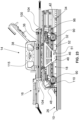
- the release lever 40 is actuated, which unlocks the locking locks 34 via a Bowden cable or similar release mechanism. This releases locking pins 42 that were previously locked by the locking locks 34 and protrude from the receiving carriage 30, so that the receiving carriage 30 can be pulled out in the direction of the arrow in the extension direction 44.
- This extension movement takes place by pulling out the receiving carriage together with the middle carriage 28.
- each of the two support structures 46 with support roller 48 arranged in the middle area of the receiving carriage 30 moves away from a hold-down pin 50 that was previously received by a receiving opening 51 in the support structure 46 (see also Fig. 5 ).
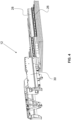
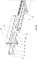
- the Fig. 3 shows the situation in which the middle carriage 28, which is guided on the guide housing 27 of the base 26, has moved to its maximum extension position. In this position, the middle carriage 28 is now locked by means of an automatically locking lock 52 (see Fig. 5 ), which can be opened automatically (later again) by actuating/acting on a release lever, on the base 26 or on its guide housing 27. At the same time, the receiving carriage 30 is unlocked from the state previously fixed to the middle carriage 28, so that the receiving carriage 30 can then be pulled out further in the pull-out direction 44.
- an automatically locking lock 52 see Fig. 5
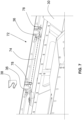
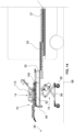
- Fig. 5 shows the situation in which the receiving carriage 30 is just before its maximum extension position (loading or unloading position).
- the locking device has a pivotable control lever 56, which is guided, for example, by a guide or the like and is provided with a roller 58 which rolls on the middle carriage 28 when the receiving carriage 30 is moved relative to the middle carriage 28 (see also Fig. 5 ).
- the control lever 56 is pivotally mounted on a pivot bearing 60 of the receiving carriage 30, and can thus be moved in the direction of the arrow 62 of the Fig. 6 pivot to the left starting from the position shown there.
- the pivot bearing end of the control lever 56 has two protruding connecting levers 64, 66, to each of which a control lever 68, 70 is articulatedly coupled, which lead from the respective levers 64, 66 to both long sides 72 of the receiving carriage 30.
- the roller 58 of the control lever 56 in the maximum extension position of the receiving carriage 30 relative to the middle carriage 28, comes to rest on a guide block 76, which ensures that the control lever 56 automatically moves in the direction of the arrow 62 of the Fig. 6 While previously the locking claws 36 were positioned in their locking position, they are now pivoted into the open position by this control lever movement and the linkage formed by the levers 64, 66, 68, 70 and the control rods 74 (see Fig. 10 ).
- the locking claws 36 release the locking hooks 38 on the patient transport device 14, which occurs at the latest after 95% or 90% or 80% or 70% or 60% or 50% or 40% of the travel from the fully retracted retraction position to the fully extended unloading and loading position of the receiving carriage 30.
- the patient transport device can either be pulled off the receiving carriage 30 in the loading or unloading position (maximum extended position) or, if the chassis 18 is present on the stretcher 16 of the patient transport device 14, the stretcher 16 can be raised above the receiving carriage 30 by extending the chassis 18 in order to then be able to move the patient transport device 14 away from the receiving carriage 30.
- each control rod 74 is provided with or coupled to an axially displaceable rack, for example, and which moves this rack, for example, in a guide-guided manner.
- the rack is in meshing engagement with a pinion or gear wheel, which is firmly connected to the control rod and rotates it when the rack is moved clockwise or counterclockwise, in order to bring the locking claws 36 into locking engagement with the locking hooks 38 or out of locking engagement with them.
- preload springs 78 (see the Fign. 7 and 9 ) tensioned.
- the pretensioning springs 78 are designed as four leg springs, the helical section of which extends around the control rods 74 in the area of the locking claws 36 and the protruding legs of which are supported on the one hand on the receiving carriage 30 and on the other hand on the locking claws 36.
- Other designs of the pretensioning device for pretensioning the locking claws 36 and thus the locking device 54 into the locking position are of course also possible.
- the special feature of the locking device 54 is that the patient transport device 14 is not locked to the receiving carriage 30 when the receiving carriage 30 is in its loading or unloading position (maximum extension). Rather, the patient transport device 14 is only locked to the receiving carriage 30 and thus to the receiving device 12 after the receiving carriage 30 has left its fully extended position, i.e. its loading or unloading position, for example after covering a maximum of 5% or a maximum of 10% or a maximum of 20% or a maximum of 30% or a maximum of 40% or a maximum of 60% of the retraction path starting from the fully extended position to the fully retracted position of the receiving carriage 30.
- the patient transport device 14 is unlocked at the latest after 95% or 90% or 80% or 70% or 60% or 50% or 40% of the travel from the fully retracted retraction position to the fully extended unloading or loading position of the receiving carriage 30.
- Figs. 11 to 19 show different views of the receiving device with and without patient transport device to illustrate the loading and unloading process to clarify.
- the middle carriage 28 is locked to the base 26 or to the guide housing 27 of the base 26 by means of the locking lock 52.
- a locking lock 80 on the receiving carriage 30, which can be opened automatically by actuating/acting on a release lever (later again) and by means of which the receiving carriage 30 is locked to the middle carriage 28 in the maximum extended position.
- the roller 58 has been moved onto the guide block 76 so that the locking claws 36 are in their open positions.
- the receiving carriage 30 has two arms 82 which form the long sides 72 of the receiving carriage 30.
- Each arm 82 is supported on the base 26 by a support structure 46 with a support roller 48 when the receiving carriage 30 is fully retracted.
- the receiving carriage 30 has handles 84, by which the receiving carriage 30 is manually gripped when the receiving carriage 30 is extended or retracted.
- Fig. 13 shows the situation in which the patient transport device 14 rests on the fully extended receiving carriage 30 with the chassis 18 retracted.
- the running or steering rollers 90 of the chassis 18 are located directly below the receiving carriage 30, i.e. are positioned above the base 26 so that the receiving carriage 30 can be pushed into the patient transport vehicle 10 or pulled out of the patient transport vehicle 10.
- Fig. 13 shows the situation in which the patient transport device 14, ie stretcher 16 and chassis 18, are positioned on the receiving carriage 30.
- the receiving carriage 30 can also be loaded only with the stretcher 16.
- the stretcher 16 has the locking hooks already mentioned above 38, which interact with the locking claws 36 of the locking device 54.
- the chassis 18 is in turn locked to the stretcher 16, for example by an upper frame (not shown) of the chassis 18 supporting the stretcher 16 and being locked to it.
- the chassis 18 has, as shown for example in the Fign. 14 and 15 shown, a height adjustment mechanism 92 in the form of a scissor lift with drive 94, which is supported on a lower frame 96, which in turn is provided with the running or steering rollers 90.
- Other height adjustment mechanisms for chassis 18 of patient transport device 14 can of course also be used.
- Fig. 14 the situation is shown in which the receiving device 12 or its receiving carriage 30 is in the loading or unloading position and the patient transport device 14 is located on the receiving carriage 30, with the chassis 18 partially extended or retracted.
- the chassis 18 thus hangs from below on the stretcher 16, so to speak.
- the stretcher 16 is not locked to the receiving carriage 30 (see the description of the locking device 54 above, which is in its unlocked position when the receiving carriage 30 is fully extended).
- the castors or steering rollers 90 of the chassis 18 finally touch the ground 98 (for example, the roadway).
- the chassis 18 is extended further, its upper frame with the stretcher 16 resting on it lifts upwards from the support carriage 30 (see Fig. 15 ).
- the patient transport device 14 can now be moved away from the receiving carriage 30.
- Fig. 16 illustrates this process again, whereby in Fig. 16 the situation is shown in which the patient transport device 14 is maneuvered to drive onto or over the receiving carriage 30.
- Fig. 17 shows area XVII of the Fig. 16 on an enlarged scale.
- the upper frame 100 of the chassis 18 is provided with locking locks (not shown) which can be unlocked by two release levers 102.
- Each longitudinal beam of the upper frame 100 is provided with a release lever 102.
- two locks arranged in the upper frame 100 per longitudinal beam can be opened via a rod which is moved by the release lever 102.
- the stretcher has locking pins or the like (also not shown) which interact with the locking locks.
- the stretcher also has roller elements 104 which taper conically towards the outside and which, as described below, serve for centering when the stretcher (in particular without the chassis 18) is pushed onto the receiving tracks 86 of the booms 82. This is because, as for example in Fig. 11 shown, the receiving tracks 86 are aligned in an outwardly tapered manner, the roller elements 104 tapering conically outwards on the stretcher lead to a centering (see Figs. 18 and 19 ).
- the previously described centering of the stretcher 16 on the arms 82 of the receiving carriage 30 is particularly required when the stretcher 16 is to be positioned on the receiving carriage 30 without the chassis 18. If, however, the stretcher 16 is on the chassis 18 or the chassis 18 is to be positioned on the receiving carriage 30 without the stretcher 16, two guide struts 106 protruding downwards from the upper frame 100 of the chassis 18, which are designed as rotating sleeves, serve to improve the maneuverability of the chassis 18.
- the guide struts 106 act with internal inlet edges on the receiving tracks 86, which form inner guide edges 108 on the two arms 82.
- the guide edges 108 are further apart from one another at the ends of the two arms 82 in the area of the respective handles 84 than in the adjoining section of the arms 82.
- the guide struts 106 are positioned on the upper frame 100 of the chassis 18 above the front steering or running rollers 90 of the chassis 18 during loading, which makes the maneuverability of the chassis 18 and the patient transport device 14 significantly easier overall, and the contact of the guide struts 106 at the level of the front steering or running rollers 90 makes it easier to thread the chassis 18 when it is not pushed onto the receiving carriage 30 in exact alignment with the free space between the two arms 82.
- Fig. 18 The centering of the chassis 18 by means of the guide struts 106 is shown in the Figs. 18 and 19 illustrated.
- Fig. 18 Another special feature. As can be seen, the guide edges 108 are convexly curved. This means that even if the chassis 18 is rotated relative to the horizontal alignment of the receiving device or the receiving carriage 30, the guide struts 106 can still be moved into the space defined by the guide edges 108. If, for example, in the situation according to Fig. 18 the chassis 18 is retracted, the chassis 18 is positioned with respect to its upper frame 100 and the stretcher 16 is automatically centered on the receiving carriage 30 or on its boom 82 (see Fig. 19 ).
- the locking lock 80 which holds the receiving carriage 30 locked relative to the middle carriage 28, released.
- the middle carriage 28 is still locked relative to the guide housing 27 of the base 26. If the receiving carriage 30 is now pushed in, it moves relative to the middle carriage 28 and along it.
- the locking device 54 locks shortly after the receiving carriage 30 leaves the loading position, i.e. is transferred from its unlocked position to the locked position, which is expediently done after the receiving carriage has covered a maximum of half, 2/3, 1/4, 1/8 or 1/10 of the travel path of the receiving carriage, starting from its loading position to its fully retracted position.
- the control lever 56 rolls off the guide block 76 via its roller 58. Due to the locking claws 36 being pre-tensioned into the locking position, the entire locking device 54 moves into the locking position. The control lever 56 pivots accordingly into the position according to Fig. 6 (see also the Fig. 21 ).
- the support structure 46 is located approximately in the middle of the patient transport device or the stretcher 16. In this exemplary embodiment, the support structure 46 is located essentially below the seat part of the stretcher 16. In this exemplary embodiment, there are fold-up side parts 115 on both sides of the seat part of the stretcher 16. Starting from the support structure 46, two struts 116 extend to the front and rear ends of the patient transport device 14. These struts 116, like the support structure 46, are part of each arm 82 of the receiving carriage 30. The struts 116 end in the area of the locking claws 36, at which the patient transport device is in locking engagement with the locking device 54 with its locking hooks 38.
- the receiving carriage 30 would experience a torque around its rear end, which is located furthest in the vehicle. However, because the patient transport device 14 is held down in its center of gravity (when loaded with a patient) by the hold-down devices 32, the torques can be absorbed. Movements of the receiving carriage 30 in the longitudinal direction are prevented by the locking locks 34. Movements of the receiving carriage 30 transversely thereto are in turn prevented by the hold-down devices 32.
- the receiving device 12 allows itself to be lifted by means of a lifting mechanism 118 when the receiving carriage 30 is completely retracted into the vehicle. If a patient transport device 14 with a patient is then located on the receiving carriage 30, it is possible to lift this patient to a height at which he or she can be comfortably cared for by the paramedic or emergency doctor during transport.
- the lifting mechanism 118 is accommodated in the guide housing 27 in a space-saving manner.
- the guide housing 27 protrudes centrally from the base 26.
- the centric U-shape of the middle carriage 28 and receiving carriage 30, in conjunction with the guide housing 27, ensures a space-saving and compact design of the receiving device 12.
- the space gained in the middle below the patient transport device 14 to be transported can now be advantageously used to accommodate the lifting mechanism 118 can be used.
- a key reason why there is space at all in this area of the receiving device 12 is that according to the invention, it is not the patient transport device 14 itself that is directly locked, for example, to the loading area 24 of the patient transport vehicle 10, but rather it is the receiving carriage 30 that is locked to the base 26 or possibly also to the loading area 24 and the patient transport device 14 is in turn locked to the receiving carriage 30. There are therefore no locking elements protruding downwards from the patient transport device 14 in order to be locked directly to the base 26 or the loading area 24 of the patient transport vehicle 10.
- the lifting mechanism 118 in this embodiment of the invention is characterized by a low overall height. It comprises two pivotable pivot arms 120, which are pivotally mounted in pivot bearings 124, which in turn are arranged below the base 26.
- the two pivot arms 120 are designed as angle arms, which extend essentially at a right angle to one another as seen from the pivot bearing 124.
- the essentially horizontally aligned first partial arm 126 is supported on a bracket 128 on the vehicle floor 22 of the patient transport vehicle 10, while the second partial arm 130 in this embodiment interacts with, for example, a spindle drive 132.
- the spindle drive 132 has a spindle 134, which interacts with spindle sleeves 136 on the partial arms 130.
- the spindle sleeve 136 moves axially on the spindle 134 and moves the arms 130 of the two pivot arms 120 towards or away from each other, so that the pivot arms 120 rotate about their pivot bearings 124. In this way, when the pivot arms 120 rotate about the pivot bearings 124, their essentially horizontal arms 126 press against the brackets 128, which causes the lifting mechanism 118 to be raised or lowered.
- the arms 126 of the two swivel arms 120 are rotatably mounted on the brackets 128.
- the brackets 128 themselves can be moved across the longitudinal extension of the ambulance vehicle 10 via a rail system or the like. This allows the receiving device 12 to be moved laterally in the ambulance vehicle 10 in order to provide more space to one side of the receiving device 12 for a paramedic or emergency doctor caring for a patient in the vehicle.
- a bellows 138 is used to cover the area below the base 26 and thus the lifting mechanism 118.
- the bellows 138 runs as a covering with two long sides and two transverse sides along the edge of the base 26, is fastened there and is mounted at its other end on the vehicle floor 22.
Landscapes
- Health & Medical Sciences (AREA)
- Public Health (AREA)
- Life Sciences & Earth Sciences (AREA)
- Animal Behavior & Ethology (AREA)
- General Health & Medical Sciences (AREA)
- Veterinary Medicine (AREA)
- Invalid Beds And Related Equipment (AREA)
Claims (22)
- Procédé de déchargement d'un dispositif de transport de malades d'un véhicule, en particulier d'une ambulance ou d'un véhicule de sauvetage, dans lequel le véhicule présente une surface de chargement (24) et, sur celle-ci, un dispositif de réception comportant un chariot de réception (30) pouvant être déployé et replié pour le dispositif de transport de malades, sur lequel chariot de réception le dispositif de transport de malades est positionné de manière à être verrouillé au moyen d'un dispositif de verrouillage (54) se trouvant dans une position de verrouillage, comportant les étapes suivantes :aa) déverrouillage du chariot de réception (30) se trouvant dans sa position de repli entièrement repliée et verrouillé dans cet état directement ou indirectement sur le véhicule (10),bb) déploiement du chariot de réception (30) jusqu'à une position de déchargement dans laquelle le chariot de réception (30) est automatiquement verrouillé et dépasse au moins partiellement vers l'arrière au-delà de la surface de chargement (24) du véhicule (10),cc) lors de la prise de la position de déchargement du chariot de réception (30), déverrouillage effectué automatiquement du dispositif de transport de malades (14) par transfert automatique du dispositif de verrouillage (54) de sa position de verrouillage à une position de déverrouillage etdd) déchargement du dispositif de transport de malades (14) du chariot de réception (30) dans sa position de déchargement.
- Procédé selon la revendication 1, caractérisé en ce que le dispositif de verrouillage (54) est bloqué dans sa position de verrouillage prise lorsque le chariot de réception (30) est dans sa position de repli entièrement repliée et en ce que ledit blocage est supprimé après ou lors de la sortie de la position de repli entièrement repliée du chariot de réception (30), laquelle sortie est effectuée lors du déploiement du chariot de réception (30).
- Procédé selon la revendication 1 ou 2, caractérisé en ce que l'étape de déchargement du dispositif de transport de malades (14) du chariot de réception (30) comprend l'étape de retrait du dispositif de transport de malades (14) du chariot de réception (30).
- Procédé selon l'une des revendications 1 à 3, caractérisé en ce que le dispositif de transport de malades (14) est un brancard (16) portable manuellement et présentant une surface de transport de patient, sans châssis (18) et en particulier sans châssis (18) réglable en hauteur, et en ce que l'étape de déchargement du dispositif de transport de malades (14) du chariot de réception (30) comprend l'étape de déchargement manuel du brancard (16) du chariot de réception (30) et l'étape de déverrouillage du dispositif de transport de malades (14) du chariot de réception (30) et l'étape de déverrouillage du brancard (16) du chariot de réception (30).
- Procédé selon l'une des revendications 1 à 3, caractérisé en ce que le dispositif de transport de malades (14) présente un châssis (18) réglable en hauteur et en particulier un châssis automatiquement réglable en hauteur comportant une surface de transport de patient et en ce que l'étape de déchargement du dispositif de transport de malades (14) du chariot de réception (30) présente les étapes partielles suivantes :- déploiement du châssis (18), lequel se trouve à l'état rétracté lors de la prise de la position de déchargement du chariot de réception (30), jusqu'à ce que le châssis (18) soit déployé jusqu'à un sol,- poursuite du déploiement du châssis (18) pour soulever le brancard (16) jusqu'au-dessus du chariot de réception (30) et- déplacement du châssis (18) avec le brancard (16) à l'écart du chariot de réception.
- Procédé selon la revendication 5, caractérisé en ce que l'étape de déverrouillage du dispositif de transport de malades (14) du chariot de réception (30) comprend l'étape de déverrouillage du châssis (18) rétracté du chariot de réception (30), dans lequel il est éventuellement prévu que le châssis (18) replié repose, dans la position de repli entièrement rétractée du chariot de réception (30) dans le véhicule (10), sur la surface de chargement (24) du véhicule (10) ou, le cas échéant, sur une base (26) du dispositif de réception (12) fixée sur la surface de chargement (24) du véhicule (10).
- Procédé selon l'une des revendications 1 à 3, caractérisé en ce
que le dispositif de transport de malades (14) présente un brancard (16) portable manuellement et pourvu d'une surface de transport de patient, lequel brancard peut être positionné sur un châssis (18) réglable en hauteur et en particulier automatiquement réglable en hauteur et peut être verrouillé avec le châssis (18) et être déverrouillé du châssis (18). - Procédé selon la revendication 7, caractérisé en ce que- l'étape de déverrouillage du dispositif de transport de malades (14) sur le chariot de réception (30) comprend l'étape de déverrouillage du châssis (18) rétracté sur le chariot de réception (30), dans lequel il est éventuellement prévu que le châssis (18) replié repose, dans la position de repli entièrement rétractée du chariot de réception (30) dans le véhicule (10), sur la surface de chargement (24) du véhicule (10) ou, le cas échéant, sur une base (26) du dispositif de réception (12) fixée sur la surface de chargement (24),
ou- que l'étape de déverrouillage du dispositif de transport de malades (14) du chariot de réception (30) comprend l'étape de déverrouillage du brancard (16) du chariot de réception (30), dans lequel il est éventuellement prévu que le châssis replié repose, dans la position de repli entièrement rétractée du chariot de réception (30) dans le véhicule (10), sur la surface de chargement (24) du véhicule (10) ou, le cas échéant, sur une base (26). - Procédé selon l'une des revendications 1 à 8, caractérisé en ce que le dispositif de réception (12) présente une base (26) montée sur la surface de chargement (24) du véhicule (10), sur laquelle base le chariot de réception (30) est guidé de manière à pouvoir se déplacer entre sa position de repli entièrement repliée et sa position de déchargement, dans lequel le chariot de réception (30) est verrouillé sur la base (26) et/ou sur la surface de chargement (24) du véhicule (10) dans sa position de repli entièrement repliée.
- Procédé selon l'une des revendications 1 à 5 et 7,
caractérisé en ce que
le dispositif de réception (12) présente une base (26) pouvant être montée sur la surface de chargement (24) du véhicule et un chariot central (28) guidé sur celle-ci de manière à pouvoir être déployé et replié, sur lequel chariot central le chariot de réception (30) est guidé de manière à pouvoir être déployé et replié, dans lequel le chariot de réception (30) est automatiquement verrouillé sur le chariot central (28) dans sa position de déploiement maximale considérée par rapport au chariot central (28), et le chariot central (28) est automatiquement verrouillé sur la base (26) et/ou sur la surface de chargement (24) du véhicule dans sa position de déploiement maximale considérée par rapport à la base (26), et dans lequel les étapes aa) à dd) comprennent les étapes suivantes :- déverrouillage du chariot de réception (30) se trouvant dans sa position de repli entièrement repliée et verrouillé dans cet état directement ou indirectement sur le véhicule (10),- déploiement du chariot de réception (30) conjointement avec le chariot central (28) verrouillé sur le chariot de réception (30) jusqu'à la position de déploiement maximale du chariot central (28) par rapport à la base (26),- dans la position de déploiement maximale du chariot central (28), verrouillage effectué automatiquement du chariot central (28) sur la base (26) et déverrouillage effectué automatiquement du chariot de réception (30) du chariot central (28),- déploiement du chariot de réception (30) sur le chariot central (28) jusqu'à la position de déploiement maximale du chariot de réception (30) par rapport au chariot central (28) pour la prise de la position de déchargement du chariot de réception (30), dans laquelle le chariot de réception (30) est automatiquement verrouillé sur le chariot central (28),- déchargement du dispositif de transport de malades (14) du chariot de réception. - Procédé selon la revendication 10, caractérisé en ce que l'étape de déploiement du chariot de réception (30) conjointement avec le chariot central (28) verrouillé sur le chariot de réception (30) jusqu'à la position de déploiement maximale du chariot central (28) par rapport à la base (26) ou l'étape de déploiement du chariot de réception (30) sur le chariot central (28) jusqu'à la position de déploiement maximale du chariot de réception (30) par rapport au chariot central (28) comprend l'étape de suppression du blocage du dispositif de verrouillage (54) dans sa position de verrouillage, laquelle suppression est effectuée après le déploiement ou au début de celui-ci.
- Procédé selon l'une des revendications 1 à 5 et 7, caractérisé en ce que
le dispositif de réception présente une base (26) pouvant être montée sur la surface de chargement (24) du véhicule et un chariot central (28) guidé sur celle-ci de manière à pouvoir être déployé et replié, sur lequel chariot central le chariot de réception (30) est guidé de manière à pouvoir être déployé et replié, dans lequel le chariot de réception (30) est automatiquement verrouillé sur le chariot central (28) dans sa position de déploiement maximale considérée par rapport au chariot central (28), et le chariot central (28) est automatiquement verrouillé sur la base (26) et/ou sur la surface de chargement (24) du véhicule dans sa position de déploiement maximale considérée par rapport à la base (26), et dans lequel les étapes aa) à dd) comprennent les étapes suivantes :- déverrouillage du chariot de réception (30) se trouvant dans sa position de repli entièrement repliée et verrouillé dans cet état directement ou indirectement sur le véhicule (10),- déploiement du chariot de réception (30) par rapport au chariot central (28) verrouillé sur la base (26) jusqu'à la position de déploiement maximale du chariot de réception (30) par rapport au chariot central (28) ainsi que, éventuellement, verrouillage effectué automatiquement du chariot de réception (30) sur le chariot central (28),- dans la position de déploiement maximale du chariot de réception (30), déverrouillage effectué automatiquement du chariot central (28) de la base (26),- déploiement du chariot central (28) sur la base (26) jusqu'à la position de déploiement maximale du chariot central (28) par rapport à la base (26) pour la prise de la position de déchargement du chariot de réception (30), dans laquelle le chariot central (28) est automatiquement verrouillé sur la base (26) ou est déjà verrouillé sur celle-ci,- déchargement du dispositif de transport de malades (14) du chariot de réception. - Procédé selon la revendication 12, caractérisé en ce que le déploiement du chariot de réception (30) par rapport au chariot central (28) verrouillé sur la base (26) jusqu'à la position de déploiement maximale du chariot de réception (30) ou l'étape de déploiement du chariot central (28) sur la base (26) jusqu'à la position de déploiement maximale du chariot central (28) par rapport à la base (26) pour la prise de la position de déchargement du chariot de réception (30) comprend l'étape de suppression du blocage du dispositif de verrouillage (54) dans sa position de verrouillage, laquelle suppression est effectuée après le déploiement ou au début de celui-ci.
- Procédé selon l'une des revendications 1 à 13, caractérisé en ce que l'étape de déverrouillage du dispositif de transport de malades (14) du chariot de réception (30) comprend l'étape de déverrouillage d'un brancard (16) du dispositif de transport de malades (14) du chariot de réception (30).
- Procédé selon l'une des revendications 1 à 14, caractérisé en ce que le dispositif de verrouillage (54) permettant de verrouiller le dispositif de transport de malades (14) sur le chariot de réception (30) présente au moins un levier de commande (56) guidé, en particulier guidé par coulisse, qui est accouplé de manière cinématique, par l'intermédiaire d'une tringlerie, à au moins un élément de verrouillage disposé de manière mobile sur le chariot de réception (30) et de préférence à respectivement deux éléments de verrouillage disposés de manière mobile sur le chariot de réception (30) pour chaque côté longitudinal du dispositif de transport de malades (14), dans lequel l'au moins un levier de commande (56) peut être déplacé entre une position de déverrouillage, dans laquelle l'au moins un élément de verrouillage dans une position de déverrouillage, dans laquelle l'au moins un élément de verrouillage (36) est hors de prise avec un élément de contre-verrouillage (38) du dispositif de transport de malades (14) qui lui est associé, et une position de verrouillage, dans laquelle l'au moins un élément de verrouillage (36) est en prise par verrouillage avec l'élément de contre-verrouillage (38) du dispositif de transport de malades (14) qui lui est associé, dans lequel l'au moins un levier de commande (56) est transféré de force de sa position de verrouillage, prise en dehors de la position de déchargement du chariot de réception (30), à sa position de déverrouillage pendant le déploiement du chariot de réception (30), et ce au plus tard dans la position de chargement du chariot de réception (30).
- Procédé selon la revendication 15, caractérisé en ce- que l'au moins un levier de commande (56) est bloqué dans la position de verrouillage au plus tard dans la position de repli entièrement repliée du chariot de réception (30) et/ou- que l'au moins un levier de commande (56) et/ou la tringlerie et/ou l'au moins un élément de verrouillage et/ou chaque élément de verrouillage sont précontraints élastiquement en direction de la position de verrouillage respective à prendre dans l'état de verrouillage du dispositif de verrouillage (54), et ce pour prendre automatiquement la position de verrouillage respective après la suppression d'un blocage potentiel lors de la coopération de l'au moins un élément de verrouillage (36) avec l'élément de contre-verrouillage (38) du dispositif de transport de malades (14) qui lui est associé, et/ou- qu'au moyen de l'au moins un levier de commande (56) et de la tringlerie, deux tiges de commande (74) comportant des griffes de verrouillage (36) peuvent être tournées vers l'avant et vers l'arrière et/ou- que la tringlerie présente deux crémaillères, dont chacune est en prise par engrènement avec une roue dentée sur une autre des deux tiges de commande (74) et/ou- que deux leviers de commande (56) comportant respectivement une tringlerie sont prévus et que chaque levier de commande (56) comportant une tringlerie est en liaison active avec une tige de commande (74) présentant des griffes de verrouillage (36) pour la rotation en avant et en arrière de la tige de commande (74) concernée.
- Procédé selon l'une des revendications 1 à 16, caractérisé en ce que la manoeuvre du dispositif de transport de malades (14) pour le transfert du dispositif de transport de malades (14) dans une position au-dessus du chariot de réception (30) comprend l'étape de centrage du dispositif de transport de malades (14) par rapport au chariot de réception (30) au moyen d'entretoises de guidage (106) dépassant du dispositif de transport de malades (14) et mobiles le long de bords de guidage (108) d'une ouverture de centrage du chariot de réception (30) et/ou en ce que les entretoises de guidage (106) et les bords de guidage (108) sont arrondis et/ou prébombés au niveau de leurs sections se touchant respectivement.
- Procédé selon la revendication 17, caractérisé en ce que la manoeuvre du dispositif de transport de malades (14) pour le transfert du dispositif de transport de malades (14) à une position au-dessus du chariot de réception (30) en s'éloignant du chariot de réception (30) comprend l'étape de centrage du dispositif de transport de malades (14) par rapport au chariot de réception (30) au moyen d'éléments de glissement ou de roulement du dispositif de transport de malades (14) pouvant être déplacés et/ou pouvant coulisser sur des voies du chariot de réception (30), dans lequel chaque voie est réalisée en saillie oblique ou est réalisée avec une section en saillie oblique.
- Procédé selon l'une des revendications 1 à 18, caractérisé en ce que- le chariot de réception (30), lorsqu'il quitte sa position de repli entièrement repliée au moyen du déploiement, s'appuie, au moyen de deux éléments de glissement ou de roulement disposés des deux côtés de son axe central, sur la surface de chargement (24) du véhicule (10) ou, le cas échéant, sur une base (26) du dispositif de réception (12) fixée sur la surface de chargement (24) du véhicule (10), dans lequel les deux éléments de glissement ou de roulement sont disposés à peu près au niveau du centre de l'extension longitudinale du chariot de réception (30) ou à peu près au niveau du centre de l'extension longitudinale du dispositif de transport de malades (14) disposé sur le chariot de réception (30),- que le dispositif de transport de malades (14) est verrouillé sur le chariot de réception (30) des deux côtés de son axe central par le dispositif de verrouillage (54) en respectivement deux points de verrouillage qui, considérés dans l'extension longitudinale du chariot de réception (30), se trouvent respectivement devant et derrière l'élément de glissement ou de roulement concerné,- que le chariot de réception (30) est renforcé des deux côtés de son axe central par des entretoises s'étendant respectivement entre chaque point de verrouillage et l'élément de glissement ou de roulement concerné et- que le chariot de réception (30), dans sa position de repli entièrement repliée, est verrouillé et/ou retenu vers le bas sur la surface de chargement (24) du véhicule (10) ou, le cas échéant, sur la base (26) fixée sur la surface de chargement (24) du véhicule (10) dans la position de repli entièrement repliée, respectivement de manière à être adjacent aux éléments de glissement ou de roulement, en particulier au moyen de dispositifs de retenue vers le bas (32) de préférence sous la forme d'éléments angulaires pouvant être placés par en dessous ou par au-dessus, et les retenues vers le bas sont libérées lorsque le chariot de réception (30) quitte la position de repli entièrement repliée ou après l'avoir quittée.
- Procédé selon la revendication 19, caractérisé en ce que le chariot de réception (30) est en outre verrouillé et éventuellement retenu vers le bas, dans sa position de de repli entièrement repliée, à son extrémité la plus éloignée dans le châssis (18) et éventuellement à l'extrémité opposée à cette extrémité, sur la surface de chargement (24) du véhicule (10) ou, le cas échéant, sur une base (26) du dispositif de réception (12) fixée sur la surface de chargement (24) du véhicule (10), à l'encontre de mouvements involontaires dans les deux directions le long de l'axe central du chariot de réception (30) et est libéré lorsque le chariot de réception (30) quitte la position de repli entièrement repliée ou après l'avoir quittée.
- Procédé selon l'une des revendications 1 à 20, caractérisé en ce que le dispositif de transport de malades (14) est verrouillé sur le chariot de réception (30), dans la position de repli entièrement repliée de celui-ci, exclusivement au moyen du dispositif de verrouillage (54), en particulier à l'encontre de forces agissant verticalement vers le haut, et, dans cet état, est fixé de manière stable en position au moyen du verrouillage du chariot de réception (30) sur le véhicule (10), en particulier sur sa surface de chargement (24) ou, le cas échéant, sur une base (26) du dispositif de réception (12) fixée sur la surface de chargement (24), éventuellement avec interposition d'un chariot central (28) entre le chariot de réception (30) et la base (26), dans lequel le chariot central (28) et le chariot de réception (30) sont verrouillés l'un à l'autre, et en ce que ladite fixation stable en position est supprimée lorsque le chariot de réception (30) quitte la position de repli entièrement repliée ou après l'avoir quittée.
- Procédé selon la revendication 21, caractérisé en ce que le dispositif de transport de patients (14) ne présente pas de verrouillage coopérant directement avec la surface de chargement (24) du véhicule (10) ou, le cas échéant, avec une base (26) du dispositif de réception (12) fixée sur la surface de chargement (24) du véhicule (10), lorsque le chariot de réception (30) se trouve dans sa position de repli entièrement repliée.
Applications Claiming Priority (1)
| Application Number | Priority Date | Filing Date | Title |
|---|---|---|---|
| PCT/EP2019/062389 WO2020228945A1 (fr) | 2019-05-14 | 2019-05-14 | Procédé de chargement et de déchargement d'un véhicule de transport de malades |
Publications (3)
| Publication Number | Publication Date |
|---|---|
| EP3738568A1 EP3738568A1 (fr) | 2020-11-18 |
| EP3738568C0 EP3738568C0 (fr) | 2025-01-01 |
| EP3738568B1 true EP3738568B1 (fr) | 2025-01-01 |
Family
ID=66668879
Family Applications (1)
| Application Number | Title | Priority Date | Filing Date |
|---|---|---|---|
| EP20174795.3A Active EP3738568B1 (fr) | 2019-05-14 | 2020-05-14 | Procédé de déchargement d'une ambulance |
Country Status (5)
| Country | Link |
|---|---|
| EP (1) | EP3738568B1 (fr) |
| DE (5) | DE112019007314A5 (fr) |
| ES (1) | ES3017909T3 (fr) |
| PL (1) | PL3738568T3 (fr) |
| WO (1) | WO2020228945A1 (fr) |
Families Citing this family (3)
| Publication number | Priority date | Publication date | Assignee | Title |
|---|---|---|---|---|
| WO2011041170A2 (fr) * | 2009-10-02 | 2011-04-07 | Stryker Corporation | Civière d'ambulance et système de chargement et de déchargement |
| US12208042B2 (en) | 2021-09-29 | 2025-01-28 | Stryker Corporation | Patient transport apparatus having an extender for a head deck section |
| CN117357344A (zh) * | 2023-11-15 | 2024-01-09 | 军事科学院系统工程研究院卫勤保障技术研究所 | 车载卧姿伤病员装卸承运装置 |
Family Cites Families (8)
| Publication number | Priority date | Publication date | Assignee | Title |
|---|---|---|---|---|
| GB2203999A (en) * | 1987-03-11 | 1988-11-02 | Macclesfield Motor Bodies | Vehicle loading platform |
| FR2682930A1 (fr) * | 1991-10-28 | 1993-04-30 | Heli Rhone Alpes | Installation sanitaire pour helicoptere notamment. |
| JP4676954B2 (ja) | 2003-01-15 | 2011-04-27 | ストライカー コーポレイション ア コーポレイション オブ ザ ステート オブ ミシガン | 救急用簡易ベッドの積み降ろし装置 |
| US10028868B2 (en) | 2014-07-08 | 2018-07-24 | Stryker Corporation | Loading and unloading apparatus |
| PL3585344T3 (pl) | 2017-02-21 | 2021-12-20 | Stollenwerk und Cie. GmbH Fabrik für Sanitätsausrüstungen | Urządzenie do transportu pacjentów |
| ES2642418B2 (es) | 2017-05-12 | 2018-07-09 | Kartsana, Sl | Sistema de anclaje de una camilla |
| DE102018111654B4 (de) | 2018-05-15 | 2025-01-02 | Stollenwerk und Cie. GmbH Fabrik für Sanitätsausrüstungen | Krankentransportvorrichtung, insbesondere für einen Kranken- oder Rettungstransportwagen |
| EP3613396A1 (fr) | 2018-08-20 | 2020-02-26 | Stollenwerk und Cie. GmbH Fabrik für Sanitätsausrüstungen | Dispositif de transport des malades |
-
2019
- 2019-05-14 WO PCT/EP2019/062389 patent/WO2020228945A1/fr not_active Ceased
- 2019-05-14 DE DE112019007314.1T patent/DE112019007314A5/de active Pending
-
2020
- 2020-05-14 DE DE202020102741.7U patent/DE202020102741U1/de active Active
- 2020-05-14 DE DE202020102743.3U patent/DE202020102743U1/de active Active
- 2020-05-14 ES ES20174795T patent/ES3017909T3/es active Active
- 2020-05-14 EP EP20174795.3A patent/EP3738568B1/fr active Active
- 2020-05-14 PL PL20174795.3T patent/PL3738568T3/pl unknown
- 2020-05-14 DE DE202020102738.7U patent/DE202020102738U1/de active Active
- 2020-05-14 DE DE202020102742.5U patent/DE202020102742U1/de active Active
Also Published As
| Publication number | Publication date |
|---|---|
| EP3738568C0 (fr) | 2025-01-01 |
| DE202020102742U1 (de) | 2020-08-18 |
| WO2020228945A1 (fr) | 2020-11-19 |
| EP3738568A1 (fr) | 2020-11-18 |
| DE202020102741U1 (de) | 2020-08-18 |
| ES3017909T3 (en) | 2025-05-14 |
| PL3738568T3 (pl) | 2025-06-16 |
| DE202020102738U1 (de) | 2020-08-18 |
| DE112019007314A5 (de) | 2022-03-17 |
| DE202020102743U1 (de) | 2020-08-18 |
Similar Documents
| Publication | Publication Date | Title |
|---|---|---|
| EP0311936B1 (fr) | Chariot pour un brancard | |
| EP3738568B1 (fr) | Procédé de déchargement d'une ambulance | |
| EP3090916B1 (fr) | Composant, comprenant un siege et une fixation de siege, destine a etre installe dans un vehicule sur rails, procede de transfert du siege d'une position de rangement dans une position d'utilisation et vehicule sur rail comprenant un tel composant | |
| DD222250A5 (de) | Eisenbahngueterwagen | |
| EP2366369A2 (fr) | Module de support | |
| DE2659602A1 (de) | Transportwagen, insbesondere krankentransportwagen | |
| DE3417599C2 (fr) | ||
| EP0893302A2 (fr) | Plateau de chargement extensible pour un véhicule | |
| EP2774794B1 (fr) | Dispositif de toit coulissant de véhicule | |
| DE2511292A1 (de) | Rollstuhl, kinderwagen, o.dgl. | |
| DE69707917T2 (de) | Fahrzeugausrüstung zur transferierung und befestigung eines in einen rollstuhl umwandelaren sitzes | |
| EP0941174B1 (fr) | Dispositif de chargement pour conteneurs ou similaire | |
| DE202021003972U1 (de) | Kraftfahrzeug mit Plattformlift-System zum sicheren Ein- und Ausladen sowie zum Befördern von Transportpersonen | |
| DE202021003975U1 (de) | Plattformlift-System zum sicheren Transport von Personen in einem Kraftfahrzeug sowie Kraftfahrzeug mit einem solchen Plattformlift-System | |
| DE1124634B (de) | Krankentransportfahrzeug mit einer Vorrichtung zur Aufnahme von Krankentragen | |
| DE8801007U1 (de) | Fahrgerät für eine Krankentrage | |
| DE102005047213B4 (de) | Bestattungsfahrzeug mit separat ausziehbaren Ladeboden-Bahnen | |
| DE1901086B2 (de) | Lastfahrzeug | |
| DE102005047214B4 (de) | Bestattungsfahrzeug mit unabhängig voneinander höhen- und längsbeweglichen Ladeboden-Bahnen | |
| DE202025106052U1 (de) | Rettungstransportfahrzeug oder Krankentransportfahrzeug mit einem Fahrzeugaufbau, einem separierten Stauraumfach und einem Lift-System dafür | |
| DE102024104838A1 (de) | Spriegelanordnung für einen Fahrzeugaufbau, Fahrzeugaufbau und Nutzfahrzeug | |
| DE202020100284U1 (de) | Beladevorrichtung für ein Bestattungsfahrzeug | |
| DE102005063328B4 (de) | Bestattungsfahrzeug mit separat ausziehbaren Ladeboden-Bahnen | |
| EP4098235A1 (fr) | Système de plate-forme élévatrice destiné au transport sécurisé des personnes dans un véhicule automobile, ainsi que véhicule automobile doté d'un tel système de plate-forme élévatrice | |
| DE1247546B (de) | Krankentransportfahrzeug mit zur Aufnahme von Krankentragen dienenden Einrichtungen |
Legal Events
| Date | Code | Title | Description |
|---|---|---|---|
| PUAI | Public reference made under article 153(3) epc to a published international application that has entered the european phase |
Free format text: ORIGINAL CODE: 0009012 |
|
| STAA | Information on the status of an ep patent application or granted ep patent |
Free format text: STATUS: THE APPLICATION HAS BEEN PUBLISHED |
|
| AK | Designated contracting states |
Kind code of ref document: A1 Designated state(s): AL AT BE BG CH CY CZ DE DK EE ES FI FR GB GR HR HU IE IS IT LI LT LU LV MC MK MT NL NO PL PT RO RS SE SI SK SM TR |
|
| AX | Request for extension of the european patent |
Extension state: BA ME |
|
| STAA | Information on the status of an ep patent application or granted ep patent |
Free format text: STATUS: REQUEST FOR EXAMINATION WAS MADE |
|
| 17P | Request for examination filed |
Effective date: 20210507 |
|
| RBV | Designated contracting states (corrected) |
Designated state(s): AL AT BE BG CH CY CZ DE DK EE ES FI FR GB GR HR HU IE IS IT LI LT LU LV MC MK MT NL NO PL PT RO RS SE SI SK SM TR |
|
| GRAP | Despatch of communication of intention to grant a patent |
Free format text: ORIGINAL CODE: EPIDOSNIGR1 |
|
| STAA | Information on the status of an ep patent application or granted ep patent |
Free format text: STATUS: GRANT OF PATENT IS INTENDED |
|
| INTG | Intention to grant announced |
Effective date: 20240723 |
|
| GRAS | Grant fee paid |
Free format text: ORIGINAL CODE: EPIDOSNIGR3 |
|
| GRAA | (expected) grant |
Free format text: ORIGINAL CODE: 0009210 |
|
| STAA | Information on the status of an ep patent application or granted ep patent |
Free format text: STATUS: THE PATENT HAS BEEN GRANTED |
|
| AK | Designated contracting states |
Kind code of ref document: B1 Designated state(s): AL AT BE BG CH CY CZ DE DK EE ES FI FR GB GR HR HU IE IS IT LI LT LU LV MC MK MT NL NO PL PT RO RS SE SI SK SM TR |
|
| REG | Reference to a national code |
Ref country code: GB Ref legal event code: FG4D Free format text: NOT ENGLISH |
|
| REG | Reference to a national code |
Ref country code: CH Ref legal event code: EP |
|
| REG | Reference to a national code |
Ref country code: DE Ref legal event code: R096 Ref document number: 502020010081 Country of ref document: DE |
|
| REG | Reference to a national code |
Ref country code: IE Ref legal event code: FG4D Free format text: LANGUAGE OF EP DOCUMENT: GERMAN |
|
| U01 | Request for unitary effect filed |
Effective date: 20250131 |
|
| U07 | Unitary effect registered |
Designated state(s): AT BE BG DE DK EE FI FR IT LT LU LV MT NL PT RO SE SI Effective date: 20250206 |
|
| U20 | Renewal fee for the european patent with unitary effect paid |
Year of fee payment: 6 Effective date: 20250515 |
|
| PGFP | Annual fee paid to national office [announced via postgrant information from national office to epo] |
Ref country code: PL Payment date: 20250507 Year of fee payment: 6 |
|
| PGFP | Annual fee paid to national office [announced via postgrant information from national office to epo] |
Ref country code: GB Payment date: 20250522 Year of fee payment: 6 Ref country code: ES Payment date: 20250616 Year of fee payment: 6 |
|
| PG25 | Lapsed in a contracting state [announced via postgrant information from national office to epo] |
Ref country code: IS Free format text: LAPSE BECAUSE OF FAILURE TO SUBMIT A TRANSLATION OF THE DESCRIPTION OR TO PAY THE FEE WITHIN THE PRESCRIBED TIME-LIMIT Effective date: 20250501 |
|
| PGFP | Annual fee paid to national office [announced via postgrant information from national office to epo] |
Ref country code: NO Payment date: 20250520 Year of fee payment: 6 |
|
| PG25 | Lapsed in a contracting state [announced via postgrant information from national office to epo] |
Ref country code: HR Free format text: LAPSE BECAUSE OF FAILURE TO SUBMIT A TRANSLATION OF THE DESCRIPTION OR TO PAY THE FEE WITHIN THE PRESCRIBED TIME-LIMIT Effective date: 20250101 |
|
| PG25 | Lapsed in a contracting state [announced via postgrant information from national office to epo] |
Ref country code: GR Free format text: LAPSE BECAUSE OF FAILURE TO SUBMIT A TRANSLATION OF THE DESCRIPTION OR TO PAY THE FEE WITHIN THE PRESCRIBED TIME-LIMIT Effective date: 20250402 |
|
| PGFP | Annual fee paid to national office [announced via postgrant information from national office to epo] |
Ref country code: CH Payment date: 20250601 Year of fee payment: 6 |
|
| PGFP | Annual fee paid to national office [announced via postgrant information from national office to epo] |
Ref country code: CZ Payment date: 20250424 Year of fee payment: 6 |
|
| PGFP | Annual fee paid to national office [announced via postgrant information from national office to epo] |
Ref country code: IE Payment date: 20250522 Year of fee payment: 6 |
|
| PG25 | Lapsed in a contracting state [announced via postgrant information from national office to epo] |
Ref country code: SM Free format text: LAPSE BECAUSE OF FAILURE TO SUBMIT A TRANSLATION OF THE DESCRIPTION OR TO PAY THE FEE WITHIN THE PRESCRIBED TIME-LIMIT Effective date: 20250101 |
|
| PG25 | Lapsed in a contracting state [announced via postgrant information from national office to epo] |
Ref country code: SK Free format text: LAPSE BECAUSE OF FAILURE TO SUBMIT A TRANSLATION OF THE DESCRIPTION OR TO PAY THE FEE WITHIN THE PRESCRIBED TIME-LIMIT Effective date: 20250101 |
|
| PLBE | No opposition filed within time limit |
Free format text: ORIGINAL CODE: 0009261 |
|
| STAA | Information on the status of an ep patent application or granted ep patent |
Free format text: STATUS: NO OPPOSITION FILED WITHIN TIME LIMIT |
|
| 26N | No opposition filed |
Effective date: 20251002 |
|
| PG25 | Lapsed in a contracting state [announced via postgrant information from national office to epo] |
Ref country code: MC Free format text: LAPSE BECAUSE OF FAILURE TO SUBMIT A TRANSLATION OF THE DESCRIPTION OR TO PAY THE FEE WITHIN THE PRESCRIBED TIME-LIMIT Effective date: 20250101 |