EP3744460B1 - Procédé de commande de soudage à l'arc - Google Patents
Procédé de commande de soudage à l'arc Download PDFInfo
- Publication number
- EP3744460B1 EP3744460B1 EP18901824.5A EP18901824A EP3744460B1 EP 3744460 B1 EP3744460 B1 EP 3744460B1 EP 18901824 A EP18901824 A EP 18901824A EP 3744460 B1 EP3744460 B1 EP 3744460B1
- Authority
- EP
- European Patent Office
- Prior art keywords
- welding
- arc
- period
- time
- base material
- Prior art date
- Legal status (The legal status is an assumption and is not a legal conclusion. Google has not performed a legal analysis and makes no representation as to the accuracy of the status listed.)
- Active
Links
Images



Classifications
-
- B—PERFORMING OPERATIONS; TRANSPORTING
- B23—MACHINE TOOLS; METAL-WORKING NOT OTHERWISE PROVIDED FOR
- B23K—SOLDERING OR UNSOLDERING; WELDING; CLADDING OR PLATING BY SOLDERING OR WELDING; CUTTING BY APPLYING HEAT LOCALLY, e.g. FLAME CUTTING; WORKING BY LASER BEAM
- B23K9/00—Arc welding or cutting
- B23K9/09—Arrangements or circuits for arc welding with pulsed current or voltage
-
- B—PERFORMING OPERATIONS; TRANSPORTING
- B23—MACHINE TOOLS; METAL-WORKING NOT OTHERWISE PROVIDED FOR
- B23K—SOLDERING OR UNSOLDERING; WELDING; CLADDING OR PLATING BY SOLDERING OR WELDING; CUTTING BY APPLYING HEAT LOCALLY, e.g. FLAME CUTTING; WORKING BY LASER BEAM
- B23K9/00—Arc welding or cutting
- B23K9/095—Monitoring or automatic control of welding parameters
- B23K9/0953—Monitoring or automatic control of welding parameters using computing means
-
- B—PERFORMING OPERATIONS; TRANSPORTING
- B23—MACHINE TOOLS; METAL-WORKING NOT OTHERWISE PROVIDED FOR
- B23K—SOLDERING OR UNSOLDERING; WELDING; CLADDING OR PLATING BY SOLDERING OR WELDING; CUTTING BY APPLYING HEAT LOCALLY, e.g. FLAME CUTTING; WORKING BY LASER BEAM
- B23K9/00—Arc welding or cutting
- B23K9/095—Monitoring or automatic control of welding parameters
-
- B—PERFORMING OPERATIONS; TRANSPORTING
- B23—MACHINE TOOLS; METAL-WORKING NOT OTHERWISE PROVIDED FOR
- B23K—SOLDERING OR UNSOLDERING; WELDING; CLADDING OR PLATING BY SOLDERING OR WELDING; CUTTING BY APPLYING HEAT LOCALLY, e.g. FLAME CUTTING; WORKING BY LASER BEAM
- B23K9/00—Arc welding or cutting
- B23K9/16—Arc welding or cutting making use of shielding gas
- B23K9/173—Arc welding or cutting making use of shielding gas and of a consumable electrode
Definitions
- the present disclosure relates to an arc welding controlling method by which welding is performed using an arc generated between a welding wire that is a consumable electrode and a base material that is a welding target.
- non-consumable electrode tungsten inert gas (TIG) welding is widely used to achieve aesthetically rippled welding beads (hereinafter, called scaly beads).
- scaly beads aesthetically rippled welding beads
- MIG metallic inert gas
- MAG metal active gas
- the consumable electrode MIG welding or MAG welding is performed by flowing current into a welding wire as an electrode to melt the welding wire with the use of an arc generated between the welding wire and the base material. This provides high deposition efficiency and increases the welding speed.
- PTL 1 and PTL 2 disclose intermittent welding methods for forming scaly beads by consumable electrode MIG welding or MAG welding. According to the intermittent welding, a series of operations is repeated: performing welding with a torch stopped for an arc ON period; stopping the torch for an arc OFF period; and moving the torch to a next welding point still in the arc OFF state to solidify the base material.
- PTL 1 and PTL 2 do not disclose a technique for facilitating change and adjustment of welding conditions.
- An object of the present invention is to provide an arc welding control method for forming scaly beads that facilitates change and adjustment of welding conditions.
- the arc welding control method is an arc welding control method for controlling arc welding, the arc welding forming a plurality of scaly beads continuously arranged on a base material in a welding cycle, the welding cycle being a sum of an arc ON period and an arc OFF period, the arc ON period being a period during which a welding current flows to a welding wire, the arc OFF period being after the arc ON period and during which the welding current does not flow to the welding wire.
- the arc welding control method includes: an initial condition setting step of setting the initial value of a welding condition for arc-welding the base material; and a scaly bead formation step of forming the plurality of scaly beads in a predetermined welding section of the base material while continuously moving a torch holding the welding wire in the predetermined welding section of the base material at a predetermined welding speed.
- the welding condition includes the arc ON period, the arc OFF period, and a plurality of welding parameters, the plurality of welding parameters including at least one of the welding current, the welding speed, and an interval between adjacent scaly beads among the scaly beads.
- the arc welding control method further includes a welding condition change step of, before the scaly bead formation step, determining whether to change the initial value based on a predetermined finish condition for the scaly beads, and when a result of the determining is affirmative, changing at least one of the plurality of welding parameters so as to satisfy the predetermined finish condition.
- the present invention it is possible to eliminate a need for complicated adjustments between the plurality of welding parameters and make an outer appearance of the scaly beads in a desired finish shape. In addition, it is possible to favorably keep quality of welding at a welding spot.
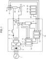
- FIG. 1 is a schematic configuration diagram of an arc welding apparatus (not part of the invention).
- Arc welding apparatus 16 uses welding wire 18 as a consumable electrode to weld base material 17 as a welding target. Welding wire 18 is held on a torch not shown. When the torch moves at a predetermined speed, a leading end of welding wire 18 moves in the same manner along a predetermined welding section at the same speed as the torch.
- Arc welding apparatus 16 includes main transformer 2, primary side rectifier 3, switcher 4, DCL (reactor) 5, secondary side rectifier 6, welding current detector 7, welding voltage detector 8, control switcher 9, output controller 10, and wire feed speed controller 13.
- Arc welding apparatus 16 also has a robot controller (not shown) that controls operations of a robot (not shown) holding the torch (not shown).
- Output controller 10 has short-circuit welding controller 11 and pulse welding controller 12.
- Wire feed speed controller 13 has wire feed speed detector 14 and arithmetic operation unit 15.
- Primary side rectifier 3 rectifies an input voltage received from an input power supply (three-phase alternating-current power supply) 1 disposed outside arc welding apparatus 16.
- Switcher 4 controls an output of primary side rectifier 3 to an output suited to welding.
- Main transformer 2 converts an output of switcher 4 to an output suited to welding.
- Secondary side rectifier 6 rectifies an output of main transformer 2.
- DCL (reactor) 5 smooths an output of secondary side rectifier 6 to a current suited to welding.
- Welding current detector 7 detects a welding current.
- Welding voltage detector 8 detects a welding voltage.
- Control switcher 9 is a switcher that outputs to output controller 10 a timing for switching from a control of short circuit welding to a control of pulse welding, from pulse welding to a cooling period.
- Control switcher 9 has a timer function, and outputs a timing for control switching to output controller 10 and wire feed speed controller 13 based on a predetermined time set by welding condition setter 22.
- the "cooling period” refers to a period during which welding current I is set to zero, and an amount of heat input from an arc becomes zero in this period (see FIG. 2 ).
- Output controller 10 outputs a control signal to switcher 4 to control a welding output.
- short-circuit welding controller 11 controls short-circuit welding.
- pulse welding controller 12 controls pulse welding.
- Wire feed speed controller 13 controls wire feeder 21 to control a feed speed of welding wire 18.
- Wire feed speed detector 14 detects the wire feed speed.
- Arithmetic operation unit 15 calculates an accumulated amount of feed amount of welding wire 18 based on the signal from wire feed speed detector 14, and controls the wire feed speed. Specifically, arithmetic operation unit 15 compares an instructive value and a detection value of the wire feed speed to determine a difference, and performs a feedback control to match the actual wire feed speed to the instructive value.
- Arc welding apparatus 16 is connected to wire feeder 21 and welding condition setter 22.
- Welding condition setter 22 is used to set the welding condition to arc welding apparatus 16.
- Welding condition setter 22 has short-circuit setter 23, pulse welding setter 24, and cooling period setter 25.
- Wire feeder 21 controls feed of welding wire 18 based on a signal from wire feed speed controller 13.
- a welding output of arc welding apparatus 16 is supplied to welding wire 18 via welding chip 20 when a torch switch (SW) not shown is turned on. Then, the welding output of arc welding apparatus 16 generates arc 19 between welding wire 18 and base material 17 as a welding target.
- SW torch switch
- arc welding apparatus 16 performs short circuit welding and pulse welding in order, and then provides a cooling period during which the welding current becomes zero such that the amount of heat input by the arc becomes zero.
- the torch (not shown) holding welding wire 18 is controlled to move in a predetermined section where welding is performed at a constant speed.
- Conventional stitch welding is intermittent welding for forming scaly beads by repeating: performing welding using a positioning jig such as a robot holding a torch, a positioner for positioning base material 17 as a welding target, or a positioning table, or manually while the movement of the torch is stopped; after the welding is temporarily stopped, relatively moving the torch to a next teaching point; and performing welding while the movement of the torch is stopped at the teaching point, in other words, by intermittent movement with repeats of stoppage and movement.
- continuous welding is performed for forming scaly beads by continuously moving the torch in a predetermined section such that the welding speed is kept constant, in other words, by continuous movement. The welding speed may not be constant over the entire welding spot of base material 17.
- the welding speed may be changed at a part of base material 17 with a change in the plate thickness.
- scaly beads can be formed by continuous movement, which makes it possible to perform high-quality and stable welding by continuous operations without influence of vibration that would be caused by a positioning mechanism such as robot, positioner, or positioning table repeating stoppage and movement or setting time that is a stabilization time until the vibration is settled.
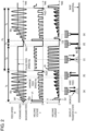
- FIG. 2 is a diagram showing various output waveforms at a time of arc welding according to the present exemplary embodiment.
- arc welding is performed with repeats of short circuit period Ts, pulse welding period Tp, and cooling period Tn.
- FIG. 2 shows temporal changes of feed speed W, welding voltage V, welding current I, and droplet transfer state D of welding wire leading end.
- feed of welding wire 18 is started at feed speed W1 from time point Wst when start of welding is instructed.
- short-circuit welding controller 11 controls a welding output under conditions set by short circuit welding setter 23 from time point Wst when the start of welding is instructed or from time point Ed when occurrence of a short circuit between welding wire 18 for which the start of welding is instructed and base material 17 as a welding target is detected.
- Arc welding apparatus 16 performs short circuit welding until a lapse of predetermined time Ts preset by short circuit welding setter 23.
- control switcher 9 switches from the short circuit welding to the pulse welding.
- Pulse welding controller 12 controls a welding output under conditions set by pulse welding setter 24 from pulse welding start time point Pst (Pst1, Pst2).
- Arc welding apparatus 16 performs pulse welding with repeats of peak current Ip and base current until a lapse of predetermined time Tp preset by pulse welding setter 24. Then, after the lapse of predetermined time Tp, control switcher 9 switches from the pulse welding to the cooling period.
- Arc welding apparatus 16 shuts off an output from output controller 10 until a lapse of predetermined time Tn set by cooling period setter 25. This makes it possible to turn the amount of heat input by the arc to zero.
- Arc welding apparatus 16 forms scaly beads with repeats of short circuit welding period Ts, pulse welding period Tp, and cooling period Tn described above in order as one welding cycle.
- short circuit welding period Ts is followed by pulse welding period Tp with a large amount of heat input.
- Pulse welding period Tp is followed by cooling period Tn during which the amount of heat input is zero. This makes it possible to enhance a cooling effect at the welding spot and maximize the difference in the amount of heat input, thereby achieving clearly rippled scaly beads.
- cooling period Tn setting the welding current and the welding voltage to zero makes it possible to set the amount of heat input to zero with highest cooling performance. Setting only the welding current to zero and continuing to apply the welding voltage makes it possible to maintain a state with occurrence of a no-load voltage and smoothly start an arc in next short circuit welding period Ts.
- a cycle from pulse welding start time point Pst1 of pulse welding period Tp to pulse welding start time point Pst2 of pulse welding period Tp in a next cycle is cycle Pc of pulse welding period.
- ripples become rougher.
- ripples become finer.
- the welding voltage is adjusted to a no-load voltage V1 that is higher than the welding voltage during pulse welding period Tp.
- the feed speed is adjusted to constant feed speed W1 until welding wire 18 causes a short circuit with base material 17 so that power distribution is detected.
- welding current I1 is larger than the welding current at the time of short circuit opening in the present welding.
- Welding current I1 is output for a predetermined period of time. During this period, welding wire 18 is fed backward with predetermined amplitude. After the short circuit opening, welding wire 18 is repeatedly fed forward and backward with the predetermined amplitude and frequency.
- a feed waveform is a sign waveform.
- the feed waveform may be any periodic waveform such as a trapezoidal waveform (not shown).
- the frequency (cycle) may be constant or variable. Feeding at a constant feed speed without predetermined amplitude and frequency is easy to control but sputtering is likely to occur due to electromagnetic pinch force at the time of short circuit opening. Accordingly, welding wire 18 is mechanically fed forward and backward with the predetermined amplitude and frequency. This suppresses the occurrence of sputtering at the time of short circuit opening in short circuit welding period Ts.
- FIG. 2 shows a droplet transfer state D at this time on the lowest side.
- State (a) indicates a droplet transfer state in the arc period of the short circuit arc welding in short circuit welding period Ts in which welding wire 18 is fed forward with generation of an arc.
- State (b) indicates a droplet transfer state in the short circuit period of short circuit arc welding in short circuit welding period Ts in which droplets at the leading end of the welding wire are transferred to base material 17 and then the wire is fed backward, thereby mechanically facilitating short circuit opening.
- the feed of welding wire 18 in pulse welding period Tp is performed at a constant feed speed optimum for the welding current set by pulse welding setter 24.
- the welding current has repeats of peak current and base current.
- the droplets at the leading end of the welding wire are separated as in state (c).
- cooling period Tn the feed speed of welding wire 18 is stopped as in state (d).
- a distance from the leading end of welding wire 18 to base material 17 is designated as WD.
- a next cycle is executed again.
- welding wire 18 is brought into contact with base material 17 and power distribution is detected, and then next short circuit welding period Ts is started again. In this manner, the arc maintained in short circuit welding period Ts and pulse welding period Tp becomes extinct in cooling period Tn.
- welding wire 18 is mechanically fed forward and backward, which makes it possible to suppress the occurrence of sputtering at the time of short circuit opening in the initial stage of arc start. That is, welding wire 18 is fed forward and backward in short circuit welding period Ts so that the short circuit is mechanically opened, thereby reducing the occurrence of sputtering due to electromagnetic pinch force.
- welding current I and feed speed W change from time to time in short circuit welding period Ts.
- average feed speed Ws of the feed speed gradually increases to approach feed speed Wc that is the same as feed speed Wp in pulse welding period Tp.
- welding wire 18 is fed with the predetermined amplitude and frequency.
- the feed of welding wire 18 is not limited to this.
- welding wire 18 may be fed at a constant feed speed.
- welding wire 18 is fed at a constant feed speed.
- the feed of welding wire 18 is not limited to this.
- the feed speed of welding wire 18 may be changed.
- average feed speed Ws is increased to a constant feed speed during pulse welding period Tp.
- the feed speed is not limited to this.
- Average feed speed Ws at an end of short circuit welding period Ts may be different form the constant feed speed during pulse welding period Tp.
- FIG. 3 is a flowchart of an arc welding procedure according to the present exemplary embodiment
- FIG. 4 is a schematic view of shapes of scaly beads.
- arc ON period A corresponds to a sum of short circuit welding period Ts and pulse welding period Tp described above
- arc OFF period B corresponds to cooling period Tn described above. That is, arc ON period A is a period during which welding current I flows in welding wire 18, and arc OFF period B is a period during which welding current I does not flow in welding wire 18.
- welding period C corresponds to a sum of arc ON period A and arc OFF period B.
- the arc ON period, arc OFF period, and welding period may be called “arc ON time T1", “arc OFF time T3", and “welding time T4", respectively.
- Welding cycle C matches cycle Pc of the pulse welding period, and welding time T4 corresponds a sum of arc ON time T1 and arc OFF time T3.
- step S1 initial conditions are set (step S1). This is an operation of assigning some welding parameters in advance to determine optimum welding conditions in order to satisfy desired finish conditions.
- the "welding parameters” include arc ON period A (arc ON time T1), arc OFF period B (arc OFF time T3), and welding cycle C (welding time T4), which are described above.
- the welding parameters include at least welding current I described above, a movement speed of a torch at the time of welding (hereinafter, called welding speed Vw), and interval G of scaly beads (see FIG. 4 ).
- the welding parameters may include, for example, welding voltage V, the feed speed of welding wire 18, and a temporal change of the feed speed.
- the initial conditions set in step S1 are, for example, conditions under which ripples of scaly beads clearly appear in a case where base materials 17 as plate materials with a plate thickness of 3.0 mm are subjected to lap welding or in a case where a joint of a predetermined shape is welded.
- the shape and material of base material 17 as a welding target vary.
- the welding conditions need to be changed in accordance with the shape and material of base material 17.
- Arc welding apparatus 16 may execute a determination process.
- arc welding apparatus 16 includes a storage unit and a processor.
- the storage unit saves judgment criteria for the determination process.
- the judgment criteria define characteristics of the base material and a mode of welding with which the ripples of scaly beads clearly appear, for example, in the case of performing arc welding under the initial conditions.
- the characteristics of the base material include, for example, thickness, shape, and material of the base material.
- the mode of welding includes information of lap welding, joint welding, and others.
- the processor acquires a data set of the characteristics of the base material to be welded and the mode of welding, and determines whether the data set satisfies the judgment criteria stored in the storage unit.
- the processor may notify the user of a determination result by display.
- step S2 When the determination is affirmative, that is, it is determined that the welding conditions need to be changed in step S2, arc welding is performed under welding conditions different from the initial conditions to form scaly beads on base material 17 (step S3). On the other hand, when the determination is negative, that is, it is not determined that the welding conditions need to be changed in step S2, the welding conditions are not changed and the arc welding is performed under the initial conditions to form scaly beads on base material 17 (step S4).
- the setting of the welding conditions under which step S3 is executed and the setting of judgment criteria for changing the welding conditions in step 2 in a case where arc welding apparatus 16 performs a determination process on change of the welding conditions in step S2 are made by inputting values input from an input device not shown, for example, a keyboard or a teaching pendant (not shown) into output controller 10 or a storage unit (not shown) connectable to output controller 10 via welding condition setter 22.
- an input device not shown for example, a keyboard or a teaching pendant (not shown) into output controller 10 or a storage unit (not shown) connectable to output controller 10 via welding condition setter 22.
- the scaly beads formed in this manner are continuously arranged with predetermined interval G on base material 17, in general, along an advancing direction of welding as shown in FIG. 4 .
- a design of outer appearance of the scaly beads is judged depending on whether interval G is constant, on whether individual beads are not too separated, or on whether ripples of a scale pattern are clear.
- a method for actually changing the welding conditions will be described taking a case of changing interval G of the beads as an example.
- interval G of the beads In general, in order to unify the outer appearance of the scaly beads, in other words, in order to improve the design of outer appearance of the scaly beads, it is preferable to keep interval G of the beads constant.
- the interval may be changed differently from the interval set as the initial condition depending on the shape of base material 17 as a welding target or the user's specifications.
- the scaly beads may not be made in a desired finish shape by merely changing interval G.
- increasing welding speed Vw along with an increase in interval G causes the ripples to be separated from each other, thereby deteriorating the design of outer appearance of the beads.
- increasing welding speed Vw reduces heat input into the welding spot. This may cause a welding defect such as insufficient melting to degrade the quality of welding at the welding spot.
- welding current I and welding voltage V As described above, in order to perform arc welding with favorable quality of welding while keeping the design of outer appearance of the beads and changing interval G, it is necessary to adjust at least six welding parameters including welding current I, welding voltage V, welding speed Vw, interval G, arc ON time T1, and arc OFF time T3 to appropriate values each time, which would be a very difficult operation.
- keeping welding speed Vw at the initial condition and keeping a ratio of arc ON time T1 to welding time T4 and a ratio of arc OFF time T3 to welding time T4 at the initial conditions make it possible to perform arc welding with favorable quality of welding while keeping the design of outer appearance of the beads and changing interval G to a desired value.
- Table 1 shows values of welding parameters with a change of interval G from 2.65 mm to 2.00 mm.
- Condition Welding parameter Welding condition Initial condition After change Change of G Arc ON time T1 (msec) 360 272 Arc OFF time T3 (msec) 170 128 Welding time T4 (msec) 530 400 Welding speed Vw (m/min) 0.30 0.30 Interval G (mm) 2.65 2.00 Arc ON rate Ron (%) 67.9 67.9 Arc OFF rate Roff (%) 32.1 32.1
- arc ON time T1 is changed to 272 msec that is a value obtained by multiplying an initial value of 360 msec by an interval G change ratio of 0.755 ( ⁇ 2/2.65).
- Arc OFF time T3 is changed to 128 msec that is a value obtained by multiplying an initial value of 170 msec by the interval G change ratio of 0.755.
- arc ON rate Ron and arc OFF rate Roff may not be necessarily held at the initial conditions. It is sufficiently possible to make the ripples clear and suppress the occurrence of pits by making individual fine adjustments to arc ON time T1 and arc OFF time T3.
- Table 2 shows values of the welding parameters with a change of arc ON time T1 or arc OFF time T3.
- Condition Welding parameter Welding condition Initial condition After change Change of T1 Arc ON time T1 (msec) 360 330 Arc OFF time T3 (msec) 170 170 Welding time T4 (msec) 530 500 Welding speed Vw (m/min) 0.30 0.30 Interval G (mm) 2.65 2.50 Arc ON rate Ron (%) 67.9 66.0 Arc OFF rate Roff (%) 32.1 34.0 Change of T3 Arc ON time T1 (msec) 360 360 Arc OFF time T3 (msec) 170 240 Welding time T4 (msec) 530 600 Welding speed Vw (m/min) 0.30 0.30 Interval G (mm) 2.65 3.00 Arc ON rate Ron (%) 67.9 60.0 Arc OFF rate Roff (%) 32.1 40.0
- the arc welding control method in the present exemplary embodiment is an arc welding control method for forming a plurality of scaly beads continuously arranged at predetermined interval G on base material 17 in welding cycle C (welding time T4) that is the sum of arc ON period A (arc ON time T1) during which welding current I flows to welding wire 18 and arc OFF period B (arc OFF time T3) that is provided after arc ON period A and during which welding current I does not flow to welding wire 18.
- the arc welding control method in the present exemplary embodiment includes: an initial condition setting step of setting a welding condition for arc-welding base material 17; and a scaly bead formation step of forming a plurality of scaly beads in a predetermined welding section of base material 17 while moving welding wire 18 in the predetermined welding section of base material 17 at predetermined welding speed Vw.
- the welding condition is formed by a plurality of welding parameters.
- the welding parameters include at least arc ON period A, arc OFF period B, welding cycle C, welding current I, welding speed Vw, and interval G.
- the control method of the present exemplary embodiment it is possible to perform arc welding with favorable quality of welding while keeping the design of outer appearance of the beads and changing interval G to a desired value.
- changing interval G while keeping welding speed Vw to match the initial condition and keeping constant arc ON rate Ron and arc OFF rate Roff makes it possible to match a heat input balance at the welding spot with the initial condition. Accordingly, the quality of welding can be favorably kept without excessive convex shapes of the beads or the occurrence of burn-through.
- At least one of arc ON period A and arc OFF period B may be changed so that at least one of welding cycle C and interval G may be changed accordingly.
- Arc OFF period B is preferably lengthened to improve the design of outer appearance of the scaly beads, or arc ON period A may be shortened.
- arc OFF period B is preferably shortened to decrease the number of pits occurring in the scaly beads.
- the welding condition change step in the present exemplary embodiment is a step of, before the scaly bead formation step, determining whether there is necessity to change the initial condition based on a predetermined finish condition for the scaly beads, and when a determination result is affirmative, changing at least one of the plurality of welding parameters so as to satisfy the predetermined finish condition. Defining the welding condition change step in this manner eliminates the complicated adjustment between the plurality of welding parameters and makes the outer appearance of the scaly beads in a desired finish shape. In addition, it is possible to favorably keep quality of welding at a welding spot.
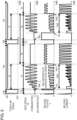
- FIG. 5 shows various output waveforms at the time of arc welding according to the present exemplary embodiment, and the waveforms correspond to indications in FIG. 2 .
- the same components as described in the first exemplary embodiment are denoted by the same reference marks, and detailed description of such components is omitted.
- the method in the present exemplary embodiment is different from the method in the first exemplary embodiment in that, in order to make uniform the ripples of the scaly beads, after a lapse of predetermined time tt since a previous torch SW signal is turned on, switching takes place from short circuit period Ts to pulse welding period Tp.
- a time after the torch SW signal is turned on is measured, and after the lapse of predetermined time tt, switching takes place from short circuit welding to pulse welding, and then after a lapse of pulse welding period Tp, the torch SW signal is turned off. Then, a time after the turning off of the torch SW signal is measured, and after a lapse of predetermined time Tn, the torch SW signal is turned on.
- changing the welding conditions in the same manner as in the first exemplary embodiment eliminates the need for complicated adjustment between the plurality of welding parameters and make the outer appearance of the scaly beads in a desired finish shape. In addition, it is possible to favorably keep quality of welding at a welding spot.
- FIG. 6 shows various output waveforms at the time of arc welding according to the present exemplary embodiment, and the waveforms correspond to indications in FIGS. 2 and 5 .
- the same components as described in the first and second exemplary embodiments are denoted by the same reference marks, and detailed description of such components is omitted.
- the method in the present exemplary embodiment is different from the methods in the first and second exemplary embodiments in that second short circuit welding period Tse is provided between pulse welding period Tp and cooling period Tn. Specifically, welding is performed by repeating first short circuit welding period Tss, pulse welding period Tp, second short circuit welding period Tse, and cooling period Tn in order as one welding cycle.
- the short circuit welding is shorter in arc length than the pulse welding and makes it possible to shorten distance WD between the leading end of welding wire 18 and base material 17 at the end of welding and reduce variations in the length of cooling period Tn.
- the distance between the leading end of welding wire 18 and base material 17 at the end of pulse welding period Tp is distance WD1.
- the distance between the leading end of welding wire 18 and base material 17 after the end of second short circuit welding period Tse is distance WD2.
- Distance WD2 is shorter than distance WD1. Accordingly, the time from feed start time point Wst of welding wire 18 to current detection time point Ed can be decreased.
- second short circuit welding period Tse an average feed speed of welding wire 18 is gradually decreased with inclination Ke. After detection of a final arc, an output of welding current I is shut off. In second short circuit welding period Tse, the average feed speed of welding wire 18 is decreased with inclination Ke such that, with the occurrence of a short circuit and an arc as one cycle, second short circuit welding period Tse is ended in about first to fifth cycles. If second short circuit welding period Tse is too long, the amount of heat input to the welding spot will increase to make unclear the ripples of the scaly beads.
- first short circuit welding period Tss pulse welding period Tp
- second short circuit welding period Tse second short circuit welding period Tse
- cooling period Tn makes it possible to make constant cycle Pc of the pulse welding period and form the scaly beads with clear and even ripples.
- a time length of second short circuit welding period Tse (hereinafter, called end active time T2) may be adjusted in accordance with a time length of first short circuit welding period Tss and/or end active time T2 such that cycle Pc of the pulse welding period becomes constant more strictly.
- Inclination Ke of the average feed speed may be changed in accordance with end active time T2.
- End active time T2 is included in arc ON time T1.
- T11 T11 + T12 + T2
- End active time T2 is the time length of second short circuit welding period Tse as described above.
- Second short circuit welding period Tse is a period of a course of transition from pulse welding period Tp to cooling period Tn.
- the feed speed of wire 18 is constant in pulse welding period Tp and is zero in cooling period Tn.
- the feed of welding wire 18 is alternately repeated forward and backward.
- the average feed speed of welding wire 18 is attenuated in second short circuit welding period Tse. Setting a predetermined value to end active time T2 makes it possible to gradually reduce the amount of heat input to base material 17.
- the wire feed speed in the end active period, is attenuated.
- the wire feed speed may be attenuated after end of the end active operation that is performed with the average value of the wire feed speed made constant while the feed of the welding wire is alternately repeated forward and backward.
- changing the welding conditions in the same manner as in the first exemplary embodiment eliminates the need for complicated adjustments between the plurality of welding parameters and make the outer appearance of the scaly beads in a desired finish shape.
- lengthening end active time T2 makes it possible to adjust a heat input balance at the welding spot and decrease the number of pits occurring in the scaly beads, thereby improving the design of outer appearance of the scaly beads.
- the amount of heat input to base material 17 may vary depending on a position of base material 17.
- the amount of heat input to base material 17 at a predetermined position may change with time.
- the amount of heat input to base material 17 greatly differs between a welding start point and a welding spot separated by a predetermined distance from this start point in a predetermined welding section. This is because, at the welding start point, an arc just starts to be generated so that insufficient heat is input to base material 17.
- the amount of heat input to base material 17 changes also when a plate thickness of base material 17 changes in the welding section.
- This change in the amount of heat input may make unstable the quality of welding and greatly deteriorate the design of outer appearance of the scaly beads.
- this spatial change or temporal change in the amount of heat input cannot be handled by merely changing the welding conditions from the initial conditions in step S2 shown in FIG. 4 .
- the foregoing issues can be solved by changing the welding conditions in such a manner as to change at least one of the welding parameters continuously or stepwise, in other words, incline and slope a change waveform of the welding parameter with respect to a teaching position and a lapse time (hereinafter, also describing this as sloping the welding parameter).
- FIG. 7A is a conceptual diagram of teaching point positions in a welding section according to the present exemplary embodiment
- FIG. 7B is a diagram showing a relationship between a distance from a welding start point and a welding parameter
- FIG. 7C is a diagram showing a relationship between a teaching point position and a welding parameter
- FIG. 7D is a diagram showing a relationship between a lapse time and a welding parameter in the scaly bead formation step.
- Which of the welding parameters is to be changed continuously or stepwise can be selected in various manners according to the actual conditions for arc welding.
- a plurality of teaching points is set at a time of teaching before the welding.
- the torch is moved from welding start point P1 along an advancing direction at predetermined welding speed Vw. Concurrently with the start of movement of the torch, arc welding is started to weld base material 17 up to welding end point Pn.
- the welding parameter may be changed continuously or stepwise according to a distance from welding start point P1 in the welding section as shown in FIG. 7B .
- an amount of change may vary in a middle of the welding section or a cycle of change may vary in the middle of the welding section.
- the welding parameter may be changed continuously or stepwise according to the teaching point positions.
- the welding parameter may be changed continuously or stepwise at each of the teaching point positions as shown by a broken line in FIG. 7C or the welding parameter may be changed continuously or stepwise at two or more each of the teaching points as shown by a dashed-dotted line in FIG.
- an amount of change may vary in a middle of the welding section or a cycle of change may vary in the middle of the welding section.
- the welding parameter may be changed continuously or stepwise according to a lapse time from the welding start point in the scaly bead formation step.
- an amount of change may vary in a middle of the welding section or a cycle of change may vary in the middle of the welding section.
- one or more of welding current I, welding voltage V, arc ON time T1, end active time T2, and arc OFF time T3 can be selected according to, for example, the state of base material 17.
- welding current I, welding voltage V, arc ON time T1, end active time T2, and arc OFF time T3 can be selected according to, for example, the state of base material 17.
- welding speed Vw is constant in the welding section.
- Table 3 shows the values of welding parameters in a case where one or more of the welding parameters are sloped.
- Condition A is an example of welding condition for solving a lack of heat input near welding start point P1.
- the beads may have an excessive convex shape or overlap together to make unclear the ripples of the scale pattern.
- arc ON time T1 and arc OFF time T3 are sloped with respect to the lapse time in the scaly bead formation step.
- the welding condition is changed such that a new slop condition is taken at each sampling time of 100 msec from the welding start time point.
- arc ON time T1 is set to 500 msec and arc OFF time T3 is set to 30 msec to increase the amount of heat input to base material 17. From this time point, arc ON time T1 and arc OFF time T3 are changed stepwise at each 100 msec so that, two seconds later, arc ON time T1 becomes 300 msec and arc OFF time T3 becomes 200 msec.
- Condition B is another example of welding condition for solving a lack of heat input near welding start point P1.
- near welding start point P1 arc ON time T1 is lengthened and arc OFF time T3 is shortened.
- arc ON time T1 is shortened and arc OFF time T3 is lengthened to approach their respective initial conditions.
- welding current I is decreased to approach the initial condition.
- Condition C is an example of welding condition in a case where heat capacity of base material 17 changes due to a change of the plate thickness of base material 17 (see FIG. 9 ) or a change of the shape of base material 17 in the welding section.
- base material 17 is shaped such that the plate thickness is smallest at point P1, then increases along the advancing direction of welding, and then becomes largest at point P2.
- welding current I is increased continuously or stepwise.
- Condition D is an example of welding condition for solving this problem.
- welding current I is decreased continuously or stepwise according to a distance from welding start point P1. Changing the welding condition in this manner makes it possible to suppress the deformation of the beads by a temperature rise of base material 17 along with the advancement of welding.
- performing welding under constant conditions may disallow obtainment of a desired finish shape or deteriorate the quality of welding.
- FIG. 8 is a schematic diagram showing an example of shape of the base material according to the present exemplary embodiment.
- Base material 17 is a saddle welded body.
- a T-shaped joint part as the welding section continuously changes in shape.
- Condition E is an example of a condition for welding the joint pat of base material 17 with the shape shown in FIG. 8 .
- Welding current I is increased continuously or stepwise as welding proceeds from welding start point P1 by a predetermined distance (15 mm). Changing the welding condition in this manner makes it possible to obtain a desired finish shape of base material 17 in which the shape of the welding section changes. In addition, it is possible to favorably keep quality of welding.
- condition E when the welding parameter is sloped in the section from welding start point P1 by a predetermined distance, even if there is a plurality of teaching points in the section, a change rate of the slop or other factors does not steeply change between before and after the teaching points.
- FIG. 9 is a schematic cross-sectional view of another base material according to the present exemplary embodiment in which a plate thickness of base material 17 simply increases from welding start point P1 to end point P2 in a welding section.
- a plate thickness of base material 17 simply increases from welding start point P1 to end point P2 in a welding section.
- Table 4 shows values of welding parameters in a case where two or more of the foregoing three welding parameters are sloped.
- Condition F is an example of welding condition for suppressing the occurrence of pits.
- lengthening end active time T2 makes it possible to decrease a number of pits that could occur in the scaly beads. However, this reduces the amount of heat input to base material 17.
- arc OFF time T3 is shortened as end active time T2 is lengthened, thereby maintaining a heat input balance in the welding section shown in FIG. 9 . Since base material 17 is subjected to short circuit welding during end active time T2, heat input to base material 17 is not zero for this period. Accordingly, shortening arc OFF time T3 by a time equivalent to an extension of end active time T2 makes heat input to base material 17 larger than being preset. Therefore, in this example, arc OFF time T3 is shortened by an amount of time shorter than the extension of end active time T2. However, since welding speed Vw is constant, interval G changes to gradually become longer in the welding section.
- Condition G is another example of welding condition for suppressing the occurrence of pits. Under condition F, arc ON time T1 is also sloped for suppressing a change of interval G.
- Changing the welding conditions as conditions F and G makes it possible to eliminate the number of pits occurring in the scaly beads and improve the design of outer appearance of the scaly beads.
- Changing the welding condition as condition G makes it possible to make interval G constant in the welding section.
- the plate thickness of base material 17 is simply increased in the welding section as an example.
- base material 17 may be reversed and the sign of the change rate may be reversed.
- an initial value of end active time T2 can be set to 60 msec and an end value of end active time T2 can be set to 2 msec under condition F so that end active time T2 is simply decreased in the welding section.
- changing the welding condition such that the value of the welding parameter is sloped during arc welding facilitates fine adjustments of a finish shape at the welding spot.
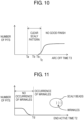
- FIG. 10 shows a relationship between arc OFF time and pit occurrence number
- FIG. 11 shows a relationship between end active time and pit occurrence number.
- Arc ON time T1 is constant in the example shown in FIG. 10
- arc ON time T1 and arc OFF time T3 are constant in the example shown in FIG. 11 .
- Times Ta to Tc described above are changed as appropriate according to arc ON time T1. Further, times Ta to Tc are also changed as appropriate by, for example, the shape of the welding spot, the thickness of base material 17, or the material of base material 17. For example, in a case of arc-welding the surface of base material 17 that is a plate material made of soft aluminum (A6061) and having a thickness of 3.0 mm, time Tb is about 120 msec to 170 msec inclusive, Ta is about 120 msec, and Tc is about 240 msec.
- arc OFF time T3 frequently has a narrow range to implement both the suppression of pit occurrence and the clearness of the scale pattern. Accordingly, even if this value is strictly set at the time of setting the initial conditions, the initial condition may not be an optimum value depending on the shape of base material 17, for example.
- sloping the values of the welding parameters including arc OFF time T3 during arc welding and changing and optimizing the welding conditions at each welding section and teaching point position makes it possible to achieve both the suppression of pit occurrence and the clearness of the scale pattern.
- the upper limit of the time during which no pits occur in the scaly beads is set to Tb.
- upper time limit Tb1 of tolerable range may be set as variation tolerable upper limit of arc OFF time T3 as far as the value causes the occurrence of pits but an amount of occurrence is tolerable from the terms of welding strength and outer appearance.
- Second short circuit welding period Tse welding wire 18 moves at constant welding speed Vw in a predetermined welding section.
- second short circuit welding period Tse there are alternate repeats of a process in which welding wire 18 and base material 17 cause a short circuit to cool base material 17 and a process in which an arc is generated between welding wire 18 and base material 17 to heat base material 17.
- marks of cooled and solidified base material 17 may appear on the surface of base material 17 at predetermined intervals.
- the marks produce an outer appearance called "wrinkles". Since the amount of heat input is large in pulse welding performed before second short circuit welding, these marks do not appear if end active time T2 is short. However, when end active time T2 becomes long, the amount of heat input to base material 17 decreases and the temperature of base material 17 becomes lower so that wrinkles start to appear. The occurrence of the wrinkles deteriorates the outer appearance of the scaly beads as with the pits and others. Accordingly, end active time T2 needs to be shorter than time Td to prevent the occurrence of wrinkles.
- end active time T2 frequently has a narrow range to achieve both the suppression of pit occurrence and the clearness of the scale pattern. Accordingly, even if this value is strictly set at the time of setting the initial conditions, the initial condition may not be an optimum value depending on the shape of base material 17, for example.
- sloping the values of the welding parameters including end active time T2 during arc welding and changing and optimizing the welding conditions at each welding section and teaching point position makes it possible to achieve both the suppression of pit occurrence and the clearness of the scale pattern.
- the movement of the torch is not stopped in the arc ON period and the arc OFF period. This increases the welding speed.
- Applying the welding method of the present invention to consumable electrode arc welding makes it possible to suppress the occurrence of sputtering by dispersion of droplets of the melted wires and others.
- the welding method of the present invention makes it possible to suppress the occurrence of blow holes and pits even if the base material is aluminum.
- the welding method of the present invention makes it possible to make a desired finish shape of outer appearance of the scaly beads in a complicated welding target subject in which the plate thickness and the work shape vary in the middle and to change the welding conditions to prevent the occurrence of welding failures.
- the arc welding controlling method of the present invention makes it possible to easily change the welding conditions and make a desired finish shape of the scaly beads, and is effectively applicable to arc welding of frames of bicycles, motorcycles, automobiles, and others.
Landscapes
- Engineering & Computer Science (AREA)
- Physics & Mathematics (AREA)
- Plasma & Fusion (AREA)
- Mechanical Engineering (AREA)
- Theoretical Computer Science (AREA)
- Arc Welding Control (AREA)
Claims (12)
- Procédé de commande de soudage à l'arc pour commander un soudage à l'arc, le soudage à l'arc formant une pluralité de cordons de soudure irréguliers agencés en continu sur un matériau de base (17) dans un cycle de soudage (Cs, T4), le cycle de soudage (Cs, T4) étant la somme d'une période MARCHE d'arc (A, Ts + Tp, T1) et d'une période ARRÊT d'arc (B, Tn, T3), la période MARCHE d'arc (A, Ts + Tp, T1) étant une période pendant laquelle un courant de soudage (I) circule dans un fil de soudage (18), la période ARRÊT d'arc (B, Tn, T3) étant une période ultérieure à la période MARCHE d'arc (A, Ts + Tp, T1) pendant laquelle le courant de soudage (I) ne circule pas dans le fil de soudage (18), le procédé de commande de soudage à l'arc comprenant :une étape de réglage de condition initiale réglant une valeur initiale d'une condition de soudage pour le soudage à l'arc du matériau de base (17) ; etune étape de formation de cordons de soudure irréguliers formant la pluralité de cordons de soudure irréguliers dans une section de soudage prédéterminée du matériau de base (17) tout en déplaçant continuellement une torche tenant le fil de soudage (18) dans la section de soudage prédéterminée du matériau de base (17) à une vitesse de soudage (Vw) prédéterminée, dans lequella condition de soudage comporte la période MARCHE d'arc (A, Ts + Tp, T1), la période ARRÊT d'arc (B, Tn, T3) et une pluralité de paramètres de soudage, la pluralité de paramètres de soudage comportant au moins un parmi le courant de soudage (I), la vitesse de soudage (Vw) et un intervalle (G) entre des cordons de soudure irréguliers adjacents parmi les cordons de soudure irréguliers, etle procédé de commande de soudage à l'arc comporte en outre une étape de modification de condition de soudage précédant l'étape de formation de cordons de soudure irréguliers, déterminant s'il faut modifier la valeur initiale sur la base d'une condition de finition prédéterminée pour les cordons de soudure irréguliers, et si le résultat de la détermination est positif, modifiant au moins un de la pluralité de paramètres de soudage de manière à satisfaire la condition de finition prédéterminée.
- Procédé de commande de soudage à l'arc selon la revendication 1, dans lequel
au cours de l'étape de modification de condition de soudage, au moins une parmi la période MARCHE d'arc et la période ARRÊT d'arc est modifiée. - Procédé de commande de soudage à l'arc selon la revendication 2, dans lequel
au cours de l'étape de modification de condition de soudage, il est fait en sorte que la période ARRÊT d'arc soit plus longue que la valeur initiale afin d'améliorer la conception de l'aspect extérieur des cordons de soudure irréguliers. - Procédé de commande de soudage à l'arc selon la revendication 2, dans lequel
au cours de l'étape de modification de condition de soudage, il est fait en sorte que la période MARCHE d'arc soit plus courte que la valeur initiale afin d'améliorer la conception de l'aspect extérieur des cordons de soudure irréguliers. - Procédé de commande de soudage à l'arc selon la revendication 2, dans lequel
au cours de l'étape de modification de condition de soudage, il est fait en sorte que la période ARRÊT d'arc soit plus courte que la valeur initiale afin de réduire un certain nombre de piqûres apparaissant dans les cordons de soudure irréguliers. - Procédé de commande de soudage à l'arc selon la revendication 1 ou 2, dans lequel
au cours de l'étape de modification de condition de soudage, la vitesse de soudage est maintenue identique à une valeur initiale, et le cycle de soudage et l'intervalle sont modifiés de manière à ce qu'un rapport de la période MARCHE d'arc sur le cycle de soudage et qu'un rapport de la période ARRÊT d'arc sur le cycle de soudage soient maintenus. - Procédé de commande de soudage à l'arc selon l'une quelconque des revendications 1 à 6, dans lequel
la période MARCHE d'arc comporte : une première période de soudage en court-circuit pendant laquelle l'alimentation du fil de soudage est répétée alternativement vers l'avant et vers l'arrière pour répéter alternativement un état où un arc est généré entre le matériau de base et le fil de soudage et un état où le matériau de base et le fil de soudage provoquent un court-circuit ; et une période de soudage par impulsion qui suit la première période de soudage en court-circuit et pendant laquelle le fil de soudage est alimenté à une vitesse d'alimentation de fil constante et un courant de crête et un courant de base circulent alternativement dans le fil de soudage pour générer un arc entre le matériau de base et le fil de soudage. - Procédé de commande de soudage à l'arc selon la revendication 7, dans lequel
la période MARCHE d'arc comporte en outre une deuxième période de soudage en court-circuit qui suit la période de soudage par impulsion, et pendant la deuxième période de soudage en court-circuit, l'alimentation du fil de soudage est répétée alternativement vers l'avant et vers l'arrière pour répéter alternativement l'état où l'arc est généré entre le matériau de base et le fil de soudage et l'état où le matériau de base et le fil de soudage provoquent le court-circuit. - Procédé de commande de soudage à l'arc selon la revendication 8, dans lequel
au cours de l'étape de modification de condition de soudage, il est fait en sorte que la deuxième période de soudage en court-circuit soit plus longue que la valeur initiale afin de réduire ledit certain nombre de piqûres apparaissant dans les cordons de soudure irréguliers. - Procédé de commande de soudage à l'arc selon l'une quelconque des revendications 7 à 9, dans lequel
au cours de l'étape de modification de condition de soudage, au moins un de la pluralité de paramètres de soudage est modifié en continu ou par étapes conformément à l'un quelconque parmi un temps écoulé au cours de l'étape de formation de cordons de soudure irréguliers, une distance par rapport à un point de départ de soudage dans la section de soudage prédéterminée et une position de point d'apprentissage de soudage. - Procédé de commande de soudage à l'arc selon la revendication 10, dans lequel
au cours de l'étape de modification de condition de soudage, au moins un de la pluralité de paramètres de soudage est modifié en continu ou par étapes conformément à une forme du matériau de base. - Procédé de commande de soudage à l'arc selon la revendication 10 ou 11, dans lequel, au cours de l'étape de modification de condition de soudage, au moins un de la pluralité de paramètres de soudage est modifié en continu ou par étapes conformément à un changement de température du matériau de base.
Applications Claiming Priority (2)
| Application Number | Priority Date | Filing Date | Title |
|---|---|---|---|
| JP2018009888 | 2018-01-24 | ||
| PCT/JP2018/046682 WO2019146318A1 (fr) | 2018-01-24 | 2018-12-19 | Procédé de commande de soudage à l'arc |
Publications (3)
| Publication Number | Publication Date |
|---|---|
| EP3744460A1 EP3744460A1 (fr) | 2020-12-02 |
| EP3744460A4 EP3744460A4 (fr) | 2021-04-07 |
| EP3744460B1 true EP3744460B1 (fr) | 2024-04-03 |
Family
ID=67395333
Family Applications (1)
| Application Number | Title | Priority Date | Filing Date |
|---|---|---|---|
| EP18901824.5A Active EP3744460B1 (fr) | 2018-01-24 | 2018-12-19 | Procédé de commande de soudage à l'arc |
Country Status (5)
| Country | Link |
|---|---|
| US (1) | US12459046B2 (fr) |
| EP (1) | EP3744460B1 (fr) |
| JP (1) | JP7149467B2 (fr) |
| CN (1) | CN111093877B (fr) |
| WO (1) | WO2019146318A1 (fr) |
Families Citing this family (13)
| Publication number | Priority date | Publication date | Assignee | Title |
|---|---|---|---|---|
| EP3599046A1 (fr) * | 2018-07-27 | 2020-01-29 | FRONIUS INTERNATIONAL GmbH | Procédé de soudage à l'arc à l'aide d'un fil fusible de soudure |
| WO2020251038A1 (fr) * | 2019-06-14 | 2020-12-17 | パナソニックIpマネジメント株式会社 | Dispositif de commande de soudage de réparation et procédé de commande de soudage de réparation |
| CN114080291B (zh) * | 2019-06-28 | 2024-05-03 | 松下知识产权经营株式会社 | 补焊系统、补焊方法、检查装置以及机器人控制装置 |
| CN112828419A (zh) * | 2020-12-31 | 2021-05-25 | 唐山松下产业机器有限公司 | 形成鱼鳞纹焊缝的焊接控制方法、装置、介质和电子设备 |
| JP2022107350A (ja) * | 2021-01-08 | 2022-07-21 | 株式会社ダイヘン | 溶接ロボット |
| JP7491860B2 (ja) * | 2021-03-03 | 2024-05-28 | 株式会社神戸製鋼所 | エレクトロスラグ溶接またはエレクトロガス溶接の制御方法、制御装置、溶接システム、およびプログラム |
| JPWO2023095623A1 (fr) * | 2021-11-29 | 2023-06-01 | ||
| CN114289830B (zh) * | 2021-12-30 | 2023-10-20 | 唐山松下产业机器有限公司 | 焊缝成型补偿方法及装置、存储介质及电子设备 |
| KR102828948B1 (ko) * | 2022-11-02 | 2025-07-03 | 한국광기술원 | 3차원 데이터 기반의 용접 상태 진단 장치 및 시스템 |
| EP4431215A1 (fr) | 2023-03-13 | 2024-09-18 | FRONIUS INTERNATIONAL GmbH | Procede d'assemblage d'intervalles de reglage |
| CN118123187B (zh) * | 2024-01-30 | 2025-09-05 | 山东奥太电气有限公司 | 一种熔化极气保焊引弧控制方法及系统 |
| JP2025163948A (ja) * | 2024-04-18 | 2025-10-30 | 株式会社ダイヘン | 積層造形システム |
| CN119304315B (zh) * | 2024-11-29 | 2026-03-06 | 唐山松下产业机器有限公司 | 一种鱼鳞纹焊接控制方法 |
Family Cites Families (34)
| Publication number | Priority date | Publication date | Assignee | Title |
|---|---|---|---|---|
| JPS61202774A (ja) | 1985-03-06 | 1986-09-08 | Nippon Kokan Kk <Nkk> | 片面炭酸ガスア−ク溶接方法 |
| JPH01237077A (ja) | 1988-03-18 | 1989-09-21 | Suzuki Motor Co Ltd | Mig溶接における溶接制御方法 |
| JPH0655268A (ja) | 1992-08-10 | 1994-03-01 | Yamaha Shatai Kogyo Kk | 溶接ロボット |
| JPH08155644A (ja) | 1994-12-02 | 1996-06-18 | Miyachi Technos Corp | アーク溶接モニタ装置 |
| JPH08257751A (ja) | 1995-03-24 | 1996-10-08 | Toshiba Corp | 自動溶接トーチ制御装置 |
| JP3768603B2 (ja) | 1995-12-11 | 2006-04-19 | 大陽日酸株式会社 | アーク溶接方法 |
| JPH106005A (ja) | 1996-06-24 | 1998-01-13 | Fanuc Ltd | アーク溶接方法 |
| ITMI20030589A1 (it) * | 2003-03-25 | 2004-09-26 | Danieli Off Mecc | Sistema e metodo per il controllo in linea di una macchina |
| JP2006130535A (ja) | 2004-11-08 | 2006-05-25 | Sansha Electric Mfg Co Ltd | 溶接方法および溶接用電源装置 |
| JP2008168321A (ja) * | 2007-01-11 | 2008-07-24 | Honda Motor Co Ltd | 溶接方法 |
| JP4995698B2 (ja) * | 2007-11-12 | 2012-08-08 | 株式会社ダイヘン | ステッチパルス溶接装置 |
| JP4995697B2 (ja) * | 2007-11-12 | 2012-08-08 | 株式会社ダイヘン | ステッチパルス溶接装置 |
| JP5102063B2 (ja) * | 2007-12-03 | 2012-12-19 | 株式会社ダイヘン | ステッチパルス溶接方法 |
| US10086461B2 (en) * | 2009-01-13 | 2018-10-02 | Lincoln Global, Inc. | Method and system to start and use combination filler wire feed and high intensity energy source for welding |
| JP5410220B2 (ja) * | 2009-09-29 | 2014-02-05 | 株式会社ダイヘン | アーク溶接方法およびアーク溶接システム |
| JP4848036B2 (ja) * | 2009-12-17 | 2011-12-28 | 株式会社ダイヘン | アーク溶接方法 |
| US8901454B2 (en) * | 2010-09-10 | 2014-12-02 | Panasonic Corporation | Arc welding control method |
| JP2012061475A (ja) * | 2010-09-14 | 2012-03-29 | Daihen Corp | アーク溶接方法、溶接電源装置、およびアーク溶接システム |
| JP5758130B2 (ja) | 2011-01-11 | 2015-08-05 | 株式会社ダイヘン | アーク溶接方法 |
| JP5808953B2 (ja) * | 2011-06-02 | 2015-11-10 | 株式会社ダイヘン | アーク溶接システムおよびアーク溶接方法 |
| EP2732901B1 (fr) * | 2011-07-12 | 2018-08-08 | Panasonic Intellectual Property Management Co., Ltd. | Procédé de commande de soudage à l'arc et dispositif de soudage à l'arc |
| EP3342521B1 (fr) * | 2012-03-16 | 2019-08-21 | Panasonic Intellectual Property Management Co., Ltd. | Dispositif de soudage à l'arc |
| US9676051B2 (en) * | 2012-10-18 | 2017-06-13 | Lincoln Global, Inc. | System and methods providing modulation schemes for achieving a weld bead appearance |
| JP2014087818A (ja) | 2012-10-30 | 2014-05-15 | Panasonic Corp | アーク溶接方法およびアーク溶接装置 |
| US10315268B2 (en) | 2012-11-07 | 2019-06-11 | Lincoln Global, Inc. | Method and system to control heat input in a welding operation |
| US10543551B2 (en) | 2013-09-16 | 2020-01-28 | Illinois Tool Works Inc. | Synchronized rotating arc welding method and system |
| US20170036288A1 (en) * | 2013-11-04 | 2017-02-09 | Illinois Tool Works Inc. | Systems and methods for selecting weld parameters |
| EP3208024B1 (fr) | 2014-10-17 | 2020-01-29 | Panasonic Intellectual Property Management Co., Ltd. | Procédé de commande de soudage à l'arc |
| US10413987B2 (en) * | 2014-11-11 | 2019-09-17 | Panasonic Intellectual Property Management Co., Ltd. | Arc welding control method |
| US10610946B2 (en) * | 2015-12-07 | 2020-04-07 | Illinois Tool Works, Inc. | Systems and methods for automated root pass welding |
| US20170246701A1 (en) * | 2016-02-29 | 2017-08-31 | Lincoln Global, Inc. | System and method for welding using rotating consumable |
| JP6778857B2 (ja) * | 2016-03-29 | 2020-11-04 | パナソニックIpマネジメント株式会社 | アーク溶接制御方法 |
| CN109715335B (zh) | 2016-09-05 | 2021-05-11 | 松下知识产权经营株式会社 | 电弧焊接控制方法 |
| US10730140B2 (en) * | 2017-08-29 | 2020-08-04 | Illinois Tool Works Inc. | Low energy, motion-assist, point-and-shoot welding torch |
-
2018
- 2018-12-19 JP JP2019567916A patent/JP7149467B2/ja active Active
- 2018-12-19 CN CN201880056892.3A patent/CN111093877B/zh active Active
- 2018-12-19 WO PCT/JP2018/046682 patent/WO2019146318A1/fr not_active Ceased
- 2018-12-19 EP EP18901824.5A patent/EP3744460B1/fr active Active
-
2020
- 2020-06-23 US US16/909,541 patent/US12459046B2/en active Active
Also Published As
| Publication number | Publication date |
|---|---|
| EP3744460A4 (fr) | 2021-04-07 |
| WO2019146318A1 (fr) | 2019-08-01 |
| JPWO2019146318A1 (ja) | 2021-01-14 |
| CN111093877A (zh) | 2020-05-01 |
| US20200316703A1 (en) | 2020-10-08 |
| JP7149467B2 (ja) | 2022-10-07 |
| US12459046B2 (en) | 2025-11-04 |
| CN111093877B (zh) | 2021-12-21 |
| EP3744460A1 (fr) | 2020-12-02 |
Similar Documents
| Publication | Publication Date | Title |
|---|---|---|
| EP3744460B1 (fr) | Procédé de commande de soudage à l'arc | |
| US12134150B2 (en) | Arc welding control method with imposed currents | |
| JP5278542B2 (ja) | アーク溶接制御方法およびアーク溶接制御装置 | |
| JPWO2018043626A1 (ja) | アーク溶接制御方法 | |
| JP6778857B2 (ja) | アーク溶接制御方法 | |
| US20090289044A1 (en) | Arc welding control method and arc welding apparatus | |
| JP7113329B2 (ja) | アーク溶接制御方法 | |
| JP6778858B2 (ja) | アーク溶接制御方法 | |
| US12121999B2 (en) | Arc-welding control method | |
| CN102794549B (zh) | 焊接装置 | |
| KR101991607B1 (ko) | 수평 필렛 용접 방법, 수평 필렛 용접 시스템 및 프로그램 | |
| KR102826171B1 (ko) | 용접 제어 방법, 용접 제어 장치, 용접 전원, 용접 시스템, 프로그램, 용접 방법 및 부가 제조 방법 | |
| CN110524089B (zh) | 电弧焊接方法以及电弧焊接装置 | |
| JP2022157591A (ja) | 溶接制御方法、溶接電源、溶接システム、溶接方法及び積層造形方法 | |
| EP4180163A1 (fr) | Système de soudage ou de fabrication additive avec alimentation d'électrode discontinue | |
| KR102493386B1 (ko) | 소모성 전극으로 용접 공정을 제어하기 위한 방법 및 이 유형의 제어기를 갖는 용접 장치 | |
| EP4509254A1 (fr) | Procédé de commande de soudage à l'arc avec électrode métallique en atmosphère de gaz, procédé de définition de condition de soudage, dispositif de commande de soudage, alimentation électrique de soudage, système de soudage, programme, procédé de soudage à l'arc avec électrode métallique en atmosphère de gaz, et procédé de fabrication additive | |
| CN119562875B (zh) | 电弧焊接方法 | |
| JP2005144468A (ja) | 交流アーク溶接のガス流量調整方法 | |
| JP2025183080A (ja) | アーク溶接方法 |
Legal Events
| Date | Code | Title | Description |
|---|---|---|---|
| STAA | Information on the status of an ep patent application or granted ep patent |
Free format text: STATUS: THE INTERNATIONAL PUBLICATION HAS BEEN MADE |
|
| PUAI | Public reference made under article 153(3) epc to a published international application that has entered the european phase |
Free format text: ORIGINAL CODE: 0009012 |
|
| STAA | Information on the status of an ep patent application or granted ep patent |
Free format text: STATUS: REQUEST FOR EXAMINATION WAS MADE |
|
| 17P | Request for examination filed |
Effective date: 20200709 |
|
| AK | Designated contracting states |
Kind code of ref document: A1 Designated state(s): AL AT BE BG CH CY CZ DE DK EE ES FI FR GB GR HR HU IE IS IT LI LT LU LV MC MK MT NL NO PL PT RO RS SE SI SK SM TR |
|
| AX | Request for extension of the european patent |
Extension state: BA ME |
|
| A4 | Supplementary search report drawn up and despatched |
Effective date: 20210309 |
|
| RIC1 | Information provided on ipc code assigned before grant |
Ipc: B23K 9/095 20060101AFI20210302BHEP Ipc: B23K 9/09 20060101ALI20210302BHEP Ipc: B23K 9/12 20060101ALI20210302BHEP |
|
| DAV | Request for validation of the european patent (deleted) | ||
| DAX | Request for extension of the european patent (deleted) | ||
| GRAP | Despatch of communication of intention to grant a patent |
Free format text: ORIGINAL CODE: EPIDOSNIGR1 |
|
| STAA | Information on the status of an ep patent application or granted ep patent |
Free format text: STATUS: GRANT OF PATENT IS INTENDED |
|
| INTG | Intention to grant announced |
Effective date: 20231103 |
|
| GRAS | Grant fee paid |
Free format text: ORIGINAL CODE: EPIDOSNIGR3 |
|
| GRAA | (expected) grant |
Free format text: ORIGINAL CODE: 0009210 |
|
| STAA | Information on the status of an ep patent application or granted ep patent |
Free format text: STATUS: THE PATENT HAS BEEN GRANTED |
|
| AK | Designated contracting states |
Kind code of ref document: B1 Designated state(s): AL AT BE BG CH CY CZ DE DK EE ES FI FR GB GR HR HU IE IS IT LI LT LU LV MC MK MT NL NO PL PT RO RS SE SI SK SM TR |
|
| REG | Reference to a national code |
Ref country code: GB Ref legal event code: FG4D |
|
| REG | Reference to a national code |
Ref country code: CH Ref legal event code: EP |
|
| REG | Reference to a national code |
Ref country code: IE Ref legal event code: FG4D |
|
| REG | Reference to a national code |
Ref country code: DE Ref legal event code: R096 Ref document number: 602018067693 Country of ref document: DE |
|
| REG | Reference to a national code |
Ref country code: LT Ref legal event code: MG9D |
|
| REG | Reference to a national code |
Ref country code: NL Ref legal event code: MP Effective date: 20240403 |
|
| REG | Reference to a national code |
Ref country code: AT Ref legal event code: MK05 Ref document number: 1671731 Country of ref document: AT Kind code of ref document: T Effective date: 20240403 |
|
| PG25 | Lapsed in a contracting state [announced via postgrant information from national office to epo] |
Ref country code: NL Free format text: LAPSE BECAUSE OF FAILURE TO SUBMIT A TRANSLATION OF THE DESCRIPTION OR TO PAY THE FEE WITHIN THE PRESCRIBED TIME-LIMIT Effective date: 20240403 |
|
| PG25 | Lapsed in a contracting state [announced via postgrant information from national office to epo] |
Ref country code: NL Free format text: LAPSE BECAUSE OF FAILURE TO SUBMIT A TRANSLATION OF THE DESCRIPTION OR TO PAY THE FEE WITHIN THE PRESCRIBED TIME-LIMIT Effective date: 20240403 |
|
| PG25 | Lapsed in a contracting state [announced via postgrant information from national office to epo] |
Ref country code: IS Free format text: LAPSE BECAUSE OF FAILURE TO SUBMIT A TRANSLATION OF THE DESCRIPTION OR TO PAY THE FEE WITHIN THE PRESCRIBED TIME-LIMIT Effective date: 20240803 |
|
| PG25 | Lapsed in a contracting state [announced via postgrant information from national office to epo] |
Ref country code: BG Free format text: LAPSE BECAUSE OF FAILURE TO SUBMIT A TRANSLATION OF THE DESCRIPTION OR TO PAY THE FEE WITHIN THE PRESCRIBED TIME-LIMIT Effective date: 20240403 |
|
| PG25 | Lapsed in a contracting state [announced via postgrant information from national office to epo] |
Ref country code: HR Free format text: LAPSE BECAUSE OF FAILURE TO SUBMIT A TRANSLATION OF THE DESCRIPTION OR TO PAY THE FEE WITHIN THE PRESCRIBED TIME-LIMIT Effective date: 20240403 Ref country code: FI Free format text: LAPSE BECAUSE OF FAILURE TO SUBMIT A TRANSLATION OF THE DESCRIPTION OR TO PAY THE FEE WITHIN THE PRESCRIBED TIME-LIMIT Effective date: 20240403 |
|
| PG25 | Lapsed in a contracting state [announced via postgrant information from national office to epo] |
Ref country code: GR Free format text: LAPSE BECAUSE OF FAILURE TO SUBMIT A TRANSLATION OF THE DESCRIPTION OR TO PAY THE FEE WITHIN THE PRESCRIBED TIME-LIMIT Effective date: 20240704 |
|
| PG25 | Lapsed in a contracting state [announced via postgrant information from national office to epo] |
Ref country code: PT Free format text: LAPSE BECAUSE OF FAILURE TO SUBMIT A TRANSLATION OF THE DESCRIPTION OR TO PAY THE FEE WITHIN THE PRESCRIBED TIME-LIMIT Effective date: 20240805 |
|
| PG25 | Lapsed in a contracting state [announced via postgrant information from national office to epo] |
Ref country code: ES Free format text: LAPSE BECAUSE OF FAILURE TO SUBMIT A TRANSLATION OF THE DESCRIPTION OR TO PAY THE FEE WITHIN THE PRESCRIBED TIME-LIMIT Effective date: 20240403 |
|
| PG25 | Lapsed in a contracting state [announced via postgrant information from national office to epo] |
Ref country code: CZ Free format text: LAPSE BECAUSE OF FAILURE TO SUBMIT A TRANSLATION OF THE DESCRIPTION OR TO PAY THE FEE WITHIN THE PRESCRIBED TIME-LIMIT Effective date: 20240403 |
|
| PG25 | Lapsed in a contracting state [announced via postgrant information from national office to epo] |
Ref country code: AT Free format text: LAPSE BECAUSE OF FAILURE TO SUBMIT A TRANSLATION OF THE DESCRIPTION OR TO PAY THE FEE WITHIN THE PRESCRIBED TIME-LIMIT Effective date: 20240403 |
|
| PG25 | Lapsed in a contracting state [announced via postgrant information from national office to epo] |
Ref country code: PL Free format text: LAPSE BECAUSE OF FAILURE TO SUBMIT A TRANSLATION OF THE DESCRIPTION OR TO PAY THE FEE WITHIN THE PRESCRIBED TIME-LIMIT Effective date: 20240403 |
|
| PG25 | Lapsed in a contracting state [announced via postgrant information from national office to epo] |
Ref country code: LV Free format text: LAPSE BECAUSE OF FAILURE TO SUBMIT A TRANSLATION OF THE DESCRIPTION OR TO PAY THE FEE WITHIN THE PRESCRIBED TIME-LIMIT Effective date: 20240403 |
|
| PG25 | Lapsed in a contracting state [announced via postgrant information from national office to epo] |
Ref country code: PT Free format text: LAPSE BECAUSE OF FAILURE TO SUBMIT A TRANSLATION OF THE DESCRIPTION OR TO PAY THE FEE WITHIN THE PRESCRIBED TIME-LIMIT Effective date: 20240805 Ref country code: PL Free format text: LAPSE BECAUSE OF FAILURE TO SUBMIT A TRANSLATION OF THE DESCRIPTION OR TO PAY THE FEE WITHIN THE PRESCRIBED TIME-LIMIT Effective date: 20240403 Ref country code: NO Free format text: LAPSE BECAUSE OF FAILURE TO SUBMIT A TRANSLATION OF THE DESCRIPTION OR TO PAY THE FEE WITHIN THE PRESCRIBED TIME-LIMIT Effective date: 20240703 Ref country code: LV Free format text: LAPSE BECAUSE OF FAILURE TO SUBMIT A TRANSLATION OF THE DESCRIPTION OR TO PAY THE FEE WITHIN THE PRESCRIBED TIME-LIMIT Effective date: 20240403 Ref country code: IS Free format text: LAPSE BECAUSE OF FAILURE TO SUBMIT A TRANSLATION OF THE DESCRIPTION OR TO PAY THE FEE WITHIN THE PRESCRIBED TIME-LIMIT Effective date: 20240803 Ref country code: HR Free format text: LAPSE BECAUSE OF FAILURE TO SUBMIT A TRANSLATION OF THE DESCRIPTION OR TO PAY THE FEE WITHIN THE PRESCRIBED TIME-LIMIT Effective date: 20240403 Ref country code: GR Free format text: LAPSE BECAUSE OF FAILURE TO SUBMIT A TRANSLATION OF THE DESCRIPTION OR TO PAY THE FEE WITHIN THE PRESCRIBED TIME-LIMIT Effective date: 20240704 Ref country code: FI Free format text: LAPSE BECAUSE OF FAILURE TO SUBMIT A TRANSLATION OF THE DESCRIPTION OR TO PAY THE FEE WITHIN THE PRESCRIBED TIME-LIMIT Effective date: 20240403 Ref country code: ES Free format text: LAPSE BECAUSE OF FAILURE TO SUBMIT A TRANSLATION OF THE DESCRIPTION OR TO PAY THE FEE WITHIN THE PRESCRIBED TIME-LIMIT Effective date: 20240403 Ref country code: CZ Free format text: LAPSE BECAUSE OF FAILURE TO SUBMIT A TRANSLATION OF THE DESCRIPTION OR TO PAY THE FEE WITHIN THE PRESCRIBED TIME-LIMIT Effective date: 20240403 Ref country code: BG Free format text: LAPSE BECAUSE OF FAILURE TO SUBMIT A TRANSLATION OF THE DESCRIPTION OR TO PAY THE FEE WITHIN THE PRESCRIBED TIME-LIMIT Effective date: 20240403 Ref country code: AT Free format text: LAPSE BECAUSE OF FAILURE TO SUBMIT A TRANSLATION OF THE DESCRIPTION OR TO PAY THE FEE WITHIN THE PRESCRIBED TIME-LIMIT Effective date: 20240403 Ref country code: RS Free format text: LAPSE BECAUSE OF FAILURE TO SUBMIT A TRANSLATION OF THE DESCRIPTION OR TO PAY THE FEE WITHIN THE PRESCRIBED TIME-LIMIT Effective date: 20240703 |
|
| REG | Reference to a national code |
Ref country code: DE Ref legal event code: R097 Ref document number: 602018067693 Country of ref document: DE |
|
| PG25 | Lapsed in a contracting state [announced via postgrant information from national office to epo] |
Ref country code: DK Free format text: LAPSE BECAUSE OF FAILURE TO SUBMIT A TRANSLATION OF THE DESCRIPTION OR TO PAY THE FEE WITHIN THE PRESCRIBED TIME-LIMIT Effective date: 20240403 |
|
| PG25 | Lapsed in a contracting state [announced via postgrant information from national office to epo] |
Ref country code: EE Free format text: LAPSE BECAUSE OF FAILURE TO SUBMIT A TRANSLATION OF THE DESCRIPTION OR TO PAY THE FEE WITHIN THE PRESCRIBED TIME-LIMIT Effective date: 20240403 |
|
| PG25 | Lapsed in a contracting state [announced via postgrant information from national office to epo] |
Ref country code: RO Free format text: LAPSE BECAUSE OF FAILURE TO SUBMIT A TRANSLATION OF THE DESCRIPTION OR TO PAY THE FEE WITHIN THE PRESCRIBED TIME-LIMIT Effective date: 20240403 Ref country code: SK Free format text: LAPSE BECAUSE OF FAILURE TO SUBMIT A TRANSLATION OF THE DESCRIPTION OR TO PAY THE FEE WITHIN THE PRESCRIBED TIME-LIMIT Effective date: 20240403 |
|
| PG25 | Lapsed in a contracting state [announced via postgrant information from national office to epo] |
Ref country code: SM Free format text: LAPSE BECAUSE OF FAILURE TO SUBMIT A TRANSLATION OF THE DESCRIPTION OR TO PAY THE FEE WITHIN THE PRESCRIBED TIME-LIMIT Effective date: 20240403 |
|
| PG25 | Lapsed in a contracting state [announced via postgrant information from national office to epo] |
Ref country code: SM Free format text: LAPSE BECAUSE OF FAILURE TO SUBMIT A TRANSLATION OF THE DESCRIPTION OR TO PAY THE FEE WITHIN THE PRESCRIBED TIME-LIMIT Effective date: 20240403 Ref country code: SK Free format text: LAPSE BECAUSE OF FAILURE TO SUBMIT A TRANSLATION OF THE DESCRIPTION OR TO PAY THE FEE WITHIN THE PRESCRIBED TIME-LIMIT Effective date: 20240403 Ref country code: RO Free format text: LAPSE BECAUSE OF FAILURE TO SUBMIT A TRANSLATION OF THE DESCRIPTION OR TO PAY THE FEE WITHIN THE PRESCRIBED TIME-LIMIT Effective date: 20240403 Ref country code: EE Free format text: LAPSE BECAUSE OF FAILURE TO SUBMIT A TRANSLATION OF THE DESCRIPTION OR TO PAY THE FEE WITHIN THE PRESCRIBED TIME-LIMIT Effective date: 20240403 Ref country code: DK Free format text: LAPSE BECAUSE OF FAILURE TO SUBMIT A TRANSLATION OF THE DESCRIPTION OR TO PAY THE FEE WITHIN THE PRESCRIBED TIME-LIMIT Effective date: 20240403 |
|
| PLBE | No opposition filed within time limit |
Free format text: ORIGINAL CODE: 0009261 |
|
| STAA | Information on the status of an ep patent application or granted ep patent |
Free format text: STATUS: NO OPPOSITION FILED WITHIN TIME LIMIT |
|
| 26N | No opposition filed |
Effective date: 20250106 |
|
| PG25 | Lapsed in a contracting state [announced via postgrant information from national office to epo] |
Ref country code: SI Free format text: LAPSE BECAUSE OF FAILURE TO SUBMIT A TRANSLATION OF THE DESCRIPTION OR TO PAY THE FEE WITHIN THE PRESCRIBED TIME-LIMIT Effective date: 20240403 |
|
| PG25 | Lapsed in a contracting state [announced via postgrant information from national office to epo] |
Ref country code: MC Free format text: LAPSE BECAUSE OF FAILURE TO SUBMIT A TRANSLATION OF THE DESCRIPTION OR TO PAY THE FEE WITHIN THE PRESCRIBED TIME-LIMIT Effective date: 20240403 |
|
| REG | Reference to a national code |
Ref country code: CH Ref legal event code: PL |
|
| PG25 | Lapsed in a contracting state [announced via postgrant information from national office to epo] |
Ref country code: LU Free format text: LAPSE BECAUSE OF NON-PAYMENT OF DUE FEES Effective date: 20241219 |
|
| GBPC | Gb: european patent ceased through non-payment of renewal fee |
Effective date: 20241219 |
|
| PG25 | Lapsed in a contracting state [announced via postgrant information from national office to epo] |
Ref country code: SE Free format text: LAPSE BECAUSE OF FAILURE TO SUBMIT A TRANSLATION OF THE DESCRIPTION OR TO PAY THE FEE WITHIN THE PRESCRIBED TIME-LIMIT Effective date: 20240403 |
|
| REG | Reference to a national code |
Ref country code: BE Ref legal event code: MM Effective date: 20241231 |
|
| PG25 | Lapsed in a contracting state [announced via postgrant information from national office to epo] |
Ref country code: GB Free format text: LAPSE BECAUSE OF NON-PAYMENT OF DUE FEES Effective date: 20241219 Ref country code: BE Free format text: LAPSE BECAUSE OF NON-PAYMENT OF DUE FEES Effective date: 20241231 |
|
| PG25 | Lapsed in a contracting state [announced via postgrant information from national office to epo] |
Ref country code: FR Free format text: LAPSE BECAUSE OF NON-PAYMENT OF DUE FEES Effective date: 20241231 |
|
| PG25 | Lapsed in a contracting state [announced via postgrant information from national office to epo] |
Ref country code: CH Free format text: LAPSE BECAUSE OF NON-PAYMENT OF DUE FEES Effective date: 20241231 |
|
| PG25 | Lapsed in a contracting state [announced via postgrant information from national office to epo] |
Ref country code: IE Free format text: LAPSE BECAUSE OF NON-PAYMENT OF DUE FEES Effective date: 20241219 |
|
| PGFP | Annual fee paid to national office [announced via postgrant information from national office to epo] |
Ref country code: DE Payment date: 20251211 Year of fee payment: 8 |
|
| PG25 | Lapsed in a contracting state [announced via postgrant information from national office to epo] |
Ref country code: IT Free format text: LAPSE BECAUSE OF FAILURE TO SUBMIT A TRANSLATION OF THE DESCRIPTION OR TO PAY THE FEE WITHIN THE PRESCRIBED TIME-LIMIT Effective date: 20240403 |