WO2019146318A1 - Procédé de commande de soudage à l'arc - Google Patents
Procédé de commande de soudage à l'arc Download PDFInfo
- Publication number
- WO2019146318A1 WO2019146318A1 PCT/JP2018/046682 JP2018046682W WO2019146318A1 WO 2019146318 A1 WO2019146318 A1 WO 2019146318A1 JP 2018046682 W JP2018046682 W JP 2018046682W WO 2019146318 A1 WO2019146318 A1 WO 2019146318A1
- Authority
- WO
- WIPO (PCT)
- Prior art keywords
- welding
- arc
- period
- time
- base material
- Prior art date
- Legal status (The legal status is an assumption and is not a legal conclusion. Google has not performed a legal analysis and makes no representation as to the accuracy of the status listed.)
- Ceased
Links
Images







Classifications
-
- B—PERFORMING OPERATIONS; TRANSPORTING
- B23—MACHINE TOOLS; METAL-WORKING NOT OTHERWISE PROVIDED FOR
- B23K—SOLDERING OR UNSOLDERING; WELDING; CLADDING OR PLATING BY SOLDERING OR WELDING; CUTTING BY APPLYING HEAT LOCALLY, e.g. FLAME CUTTING; WORKING BY LASER BEAM
- B23K9/00—Arc welding or cutting
- B23K9/095—Monitoring or automatic control of welding parameters
- B23K9/0953—Monitoring or automatic control of welding parameters using computing means
-
- B—PERFORMING OPERATIONS; TRANSPORTING
- B23—MACHINE TOOLS; METAL-WORKING NOT OTHERWISE PROVIDED FOR
- B23K—SOLDERING OR UNSOLDERING; WELDING; CLADDING OR PLATING BY SOLDERING OR WELDING; CUTTING BY APPLYING HEAT LOCALLY, e.g. FLAME CUTTING; WORKING BY LASER BEAM
- B23K9/00—Arc welding or cutting
- B23K9/09—Arrangements or circuits for arc welding with pulsed current or voltage
-
- B—PERFORMING OPERATIONS; TRANSPORTING
- B23—MACHINE TOOLS; METAL-WORKING NOT OTHERWISE PROVIDED FOR
- B23K—SOLDERING OR UNSOLDERING; WELDING; CLADDING OR PLATING BY SOLDERING OR WELDING; CUTTING BY APPLYING HEAT LOCALLY, e.g. FLAME CUTTING; WORKING BY LASER BEAM
- B23K9/00—Arc welding or cutting
- B23K9/095—Monitoring or automatic control of welding parameters
-
- B—PERFORMING OPERATIONS; TRANSPORTING
- B23—MACHINE TOOLS; METAL-WORKING NOT OTHERWISE PROVIDED FOR
- B23K—SOLDERING OR UNSOLDERING; WELDING; CLADDING OR PLATING BY SOLDERING OR WELDING; CUTTING BY APPLYING HEAT LOCALLY, e.g. FLAME CUTTING; WORKING BY LASER BEAM
- B23K9/00—Arc welding or cutting
- B23K9/16—Arc welding or cutting making use of shielding gas
- B23K9/173—Arc welding or cutting making use of shielding gas and of a consumable electrode
Definitions
- the present disclosure relates to a control method of arc welding in which welding is performed using an arc generated between a welding wire which is a consumable electrode and a base material which is an object to be welded.
- non-consumable electrode type TIG welding is widely used in order to realize a beautiful wavy weld bead (hereinafter referred to as a wedge-shaped bead).
- a wedge-shaped bead In recent years, from the viewpoint of productivity improvement, there is a demand for replacing non-consumable electrode type TIG welding with consumable electrode type MIG welding or MAG welding.
- non-consumable electrode type TIG welding since the electrode does not melt, it is necessary to supply a filler metal separately from the electrode in welding of a strength part which needs to increase the bead build-up.
- Patent Document 1 discloses intermittent welding as a welding method for forming a wedge-shaped bead by consumable electrode type MIG welding or mag welding.
- this intermittent welding welding is performed with the torch stopped in the arc ON period, and then the torch is stopped in the arc OFF period, and then the torch is moved with the arc OFF to move to the next welding point and the base material Repeat a series of actions to coagulate.
- Patent Document 1 does not disclose a technique for easily changing or adjusting welding conditions.
- a control method of arc welding includes an arc ON period in which a welding current flows in the welding wire and an arc OFF period provided after the arc ON period and in which the welding current does not flow in the welding wire
- a control method of arc welding in which a plurality of wedge-shaped beads continuously arranged in a base material are formed by setting the sum of the above and the above as a welding cycle, and initial condition setting for setting an initial value of welding conditions for arc welding a base material
- the welding condition is provided with a process and a hooked bead forming process of forming a plurality of hooked beads in a predetermined welding section of the base material while moving a predetermined welding section of the base material at a predetermined welding speed, and the welding conditions are , Comprising an arc ON period and an arc OFF period, and further comprising a plurality of welding parameters including at least one of welding current, welding speed and pitch of each bead of the wedge-shaped bead Before the wedge-shaped bea
- FIG. 1 is a view showing a schematic configuration of an arc welding apparatus according to the present embodiment.
- the arc welding apparatus 16 welds the base material 17 which is an object to be welded, using a welding wire 18 which is a consumable electrode.
- the welding wire 18 is held by a torch (not shown), and moving the torch at a predetermined speed moves the tip of the welding wire 18 along the predetermined welding section at the same speed as the torch. .
- the arc welding apparatus 16 includes a main transformer 2, a primary side rectification unit 3, a switching unit 4, a DCL (reactor) 5, a secondary side rectification unit 6, a welding current detection unit 7, and a welding voltage detection unit A control switching unit 9, an output control unit 10, and a wire feeding speed control unit 13 are provided.
- the arc welding apparatus 16 further includes a robot control unit (not shown) that controls the operation of a robot (not shown) that holds a torch (not shown).
- the output control unit 10 includes a short circuit welding control unit 11 and a pulse welding control unit 12.
- the wire feeding speed control unit 13 has a wire feeding speed detection unit 14 and a calculation unit 15.
- the primary side rectifying unit 3 rectifies an input voltage received from an input power supply (three-phase AC power supply) 1 located outside the arc welding apparatus 16.
- the switching unit 4 controls the output of the primary side rectifying unit 3 to an output suitable for welding.
- the main transformer 2 converts the output of the switching unit 4 into an output suitable for welding.
- the secondary side rectifier 6 rectifies the output of the main transformer 2.
- the DCL (reactor) 5 smoothes the output of the secondary side rectifier 6 to a current suitable for welding.
- the welding current detection unit 7 detects a welding current.
- the welding voltage detection unit 8 detects a welding voltage.
- the control switching unit 9 is a switching unit that outputs, to the output control unit 10, the timing of switching from control of short circuit welding to control of pulse welding and pulse welding to a cooling period.
- the control switching unit 9 has a clocking function, and outputs timing to switch control to the output control unit 10 and the wire feeding speed control unit 13 based on the predetermined time set by the welding condition setting unit 22.
- the “cooling period” is a period in which the welding current I is set to 0, and in this period, the amount of heat input from the arc is 0 (see FIG. 2).
- the output control unit 10 outputs a control signal to the switching unit 4 to control the welding output.
- the short circuit welding control unit 11 controls the short circuit welding when the control switching unit 9 instructs the short circuit welding.
- the pulse welding control unit 12 controls the pulse welding when the control switching unit 9 instructs the pulse welding.
- the wire feeding speed control unit 13 controls the wire feeding unit 21 to control the feeding speed of the welding wire 18.
- the wire feeding speed detection unit 14 detects a wire feeding speed.
- the calculation unit 15 calculates the integrated amount of the feed amount of the welding wire 18 based on the signal from the wire feed speed detection unit 14 and controls the wire feed speed. Specifically, the arithmetic unit 15 compares the command value of the wire feeding speed with the detected value to obtain a difference, and adjusts the actual wire feeding speed to the command value based on the integrated amount of the difference. Perform feedback control.
- the wire feeding unit 21 and the welding condition setting unit 22 are connected to the arc welding apparatus 16.
- the welding condition setting unit 22 is used to set welding conditions in the arc welding apparatus 16.
- the welding condition setting unit 22 further includes a short circuit welding setting unit 23, a pulse welding setting unit 24, and a cooling period setting unit 25.
- the wire feeding unit 21 controls feeding of the welding wire 18 based on a signal from the wire feeding speed control unit 13.
- the welding output of the arc welding apparatus 16 is supplied to the welding wire 18 through the welding tip 20 when the torch SW (switch) not shown is turned on. And, the welding output of the arc welding apparatus 16 generates an arc 19 between the welding wire 18 and the base material 17 which is the object to be welded.
- the arc welding apparatus 16 which provides the control method of the arc welding for forming the scaly bead configured as described above will be described using FIG.
- the arc welding apparatus 16 performs short circuit welding and pulse welding in order, and then provides a cooling period in which the welding current is zero so as to make the heat input by the arc zero.
- the torch (not shown) holding the welding wire 18 is controlled to move at a constant speed in a predetermined section where welding is performed.
- the time during which the movement of the torch is stopped using a robot holding the torch, a positioner for positioning the base material 17 which is the object to be welded, a positioning jig such as a positioning table, or manually The welding is temporarily stopped and then the torch is moved relatively to the next teaching point, and the welding operation is repeated during the time when the movement of the torch is stopped at the teaching point to form a wedge-shaped bead
- it is intermittent welding which forms a bowl-like bead by intermittent movement which repeats stop and movement.
- the torch is moved continuously so that the welding speed is kept constant in a predetermined section, in other words, continuous welding which forms a scaly bead by continuous movement.
- the welding speed may not be constant over the entire welding portion of the base material 17.
- the welding speed may be changed at a portion where the thickness of the base material 17 changes.
- the vibration generated when the positioning mechanism such as the robot, the positioner, and the positioning table repeats stop and movement, and the vibration settles. High quality and stable continuous operation welding is possible without being affected by the settling time, which is the settling time until
- FIG. 2 is a view showing various output waveforms at the time of arc welding according to the present embodiment.
- the arc welding repeats the short circuit welding period Ts, the pulse welding period Tp, and the cooling period Tn.
- FIG. 2 shows the time change of the feed speed W, the welding voltage V, the welding current I, and the droplet transition state D of the welding wire tip.
- the feeding of the welding wire 18 is started at the feeding speed W1 from the time point Wst when the start of welding is instructed.
- the conditions set by the short circuit welding setting unit 23 from the time Wst when the start of welding is instructed or from the time Ed when the occurrence of a short circuit between the welding wire 18 and the base material 17 which is the welding object is detected from the time Wst The welding output is controlled by the short circuit welding control unit 11 at step S2.
- the arc welding apparatus 16 performs short circuit welding until a predetermined time Ts set in advance by the short circuit welding setting unit 23 elapses.
- the control switching unit 9 switches from short circuit welding to pulse welding.
- the welding output is controlled by the pulse welding control unit 12 under the conditions set by the pulse welding setting unit 24 from the pulse welding start time point Pst (Pst1, Pst2).
- the arc welding apparatus 16 performs pulse welding which repeats the peak current Ip and the base current until a predetermined time Tp set in advance by the pulse welding setting unit 24 elapses. Then, when a predetermined time Tp has elapsed, the control switching unit 9 switches from pulse welding to a cooling period.
- the arc welding apparatus 16 shuts off the output from the output control unit 10 until the predetermined time Tn set by the cooling period setting unit 25 elapses. Thereby, the heat input by the arc can be made zero.
- the arc welding apparatus 16 forms a wedge-shaped bead by sequentially repeating the above-mentioned short circuit welding period Ts, pulse welding period Tp, and cooling period Tn as one welding cycle.
- a short welding period Ts is followed by a pulse welding period Tp having a high heat input.
- the pulse welding period Tp is followed by a cooling period Tn in which the heat input is zero.
- the cooling period Tn if the welding current and the welding voltage are made zero, the heat input can be made zero and the cooling property is the best.
- the no-load voltage can be maintained, and the arc start can be smoothly performed in the next short circuit welding period Ts.
- the cycle from the pulse welding start point Pst1 of the pulse welding period Tp to the pulse welding start point Pst2 of the pulse welding period Tp of the next cycle is a period Pc of the pulse welding period.
- a molten pool is not formed immediately below the arc at the time of arc generation in the pulse welding period Tp, droplets of the welding wire 18 are blown off at the time of outputting the peak current Ip of the pulse and spatter occurs. Therefore, the short circuit welding period Ts is provided before the pulse welding period Tp. As a result, a molten pool is formed immediately below the arc when switching from the short circuit welding period Ts to the pulse welding period Tp, and the generation of spatter due to the pulse current can be suppressed.
- the welding voltage is adjusted to the no-load voltage V1 higher than the welding voltage during the pulse welding period Tp.
- the feeding speed is adjusted to a constant feeding speed W1 until the welding wire 18 is short-circuited with the base material 17 and energization is detected.
- the welding current I1 after the detection of energization is larger than the welding current at the time of the short circuit opening of this welding.
- Welding current I1 is output for a predetermined period. During this period, the delivery of welding wire 18 is backfed with a predetermined amplitude. After the short circuit is opened, the welding wire 18 is fed while repeating forward and reverse feeding with a predetermined amplitude and frequency.
- any feeding waveform such as a trapezoidal wave (not shown) may be used as long as it is a periodic waveform.
- the frequency (period) may be constant or may be variable. Further, if feeding is performed at a constant feeding speed without having a predetermined amplitude and frequency, etc., management is easy, but spattering due to electromagnetic pinching force is likely to occur when the short circuit is opened. Therefore, the welding wire 18 is mechanically forward fed and reverse fed at a predetermined amplitude and frequency. By this, it is possible to suppress the generation of spatter at the time of the short circuit opening in the short circuit welding period Ts.
- the droplet transition state D at this time is shown at the bottom of FIG.
- State (a) shows the droplet transition state of the arc period of the short circuit arc welding during the short circuit welding period Ts, and the welding wire 18 is fed forward while generating the arc.
- State (b) shows the droplet transfer state of the short circuit period of the short circuit arc welding during the short circuit welding period Ts, and after the droplets of the welding wire tip are transferred to the base material 17, the wire is transported backward to mechanically It urges short circuit opening.
- the feeding of the welding wire 18 in the pulse welding period Tp is performed at a constant feeding speed that is optimum for the welding current set by the pulse welding setting unit 24.
- the welding current repeats peak current and base current.
- the droplets at the welding wire tip break off as shown in state (c).
- the feeding speed of the welding wire 18 is stopped.
- the distance from the tip of welding wire 18 at that time to base material 17 is WD.
- the next cycle is performed again.
- the next short circuit welding period Ts is started again.
- the arc maintained in the short circuit welding period Ts and the pulse welding period Tp disappears in the cooling period Tn.
- the welding current I and the feeding speed W in the short circuit welding period Ts change every moment.
- the average feed speed Ws of the feed speed gradually increases so as to approach the same feed speed Wc as the feed speed Wp of the pulse welding period Tp.
- Welding is performed in a cycle in which the short circuit welding period Ts, the pulse welding period Tp, and the cooling period Tn are sequentially repeated as described above, and the low heat input short circuit welding, the high heat input pulse welding, and the heat input zero cooling period.
- the heat input to the base material 17 can be widely controlled, and the weld bead shape can be more precisely controlled.
- the welding wire 18 is fed at a predetermined amplitude and frequency, but is not limited thereto. As mentioned above, the welding wire 18 may be fed at a constant feed rate during the short circuit welding period Ts to facilitate control.
- the welding wire 18 is fed at a constant feeding speed, but is not limited thereto.
- the feeding speed of the welding wire 18 may be varied.
- the average feed speed Ws is increased to the constant feed speed during the pulse welding period Tp during the short circuit welding period Ts, the present invention is not limited thereto.
- the average feed speed Ws at the end of the short circuit welding period Ts may be different from the constant feed speed during the pulse welding period Tp.
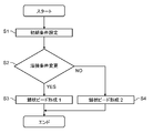
- FIG. 3 shows a flow chart showing an arc welding procedure according to the present embodiment
- FIG. 4 shows a schematic view of the shape of a wedge-shaped bead.
- the “arc ON period A” corresponds to the sum of the short circuit welding period Ts and the pulse welding period Tp unless otherwise specified
- the “arc OFF period B” is the cooling period described above. It corresponds to Tn. That is, the arc ON period A is a period in which the welding current I flows in the welding wire 18, and the arc OFF period B is a period in which the welding current I does not flow in the welding wire 18.
- the “welding cycle C” corresponds to the sum of the arc ON period A and the arc OFF period B.
- arc ON time T1 when focusing on the time length in the arc ON period, the arc OFF period, and the welding cycle, it may be referred to as “arc ON time T1”, “arc OFF time T3”, and “welding time T4”, respectively.
- the welding cycle C corresponds to the cycle Pc of the pulse welding period described above, and the welding time T4 corresponds to the sum of the arc ON time T1 and the arc OFF time T3.
- step S1 This is an operation in which some welding parameters are shaken in advance to find an optimum welding condition so as to satisfy a desired finish condition.
- the above-mentioned arc ON period A (arc ON time T1)
- arc OFF period B (arc OFF time T3)
- welding cycle C (welding time T4) are included in the “welding parameters”. Is included.
- the welding parameters include at least the welding current I, the moving speed of the torch at the time of welding (hereinafter referred to as welding speed Vw), and the pitch G of the scissor bead (see FIG. 4).
- the welding parameters may include, for example, the welding voltage V, the feeding speed of the welding wire 18, and the time change thereof.
- step S2 it is determined whether arc welding is actually performed or arc welding is performed under another condition according to the above-described initial conditions. In other words, it is determined whether the welding condition needs to be changed (step S2).
- the initial conditions set in step S1 are, for example, when the base materials 17 which are plate members having a plate thickness of 3.0 mm are overlapped and welded, or when a joint having a predetermined shape is welded, the corrugation of the wedge-shaped bead is It is a condition that appears clearly.
- the shape and material of the base material 17 to be welded are various, and when the arc welding is performed according to the initial conditions, the welding point May not be the desired finish. In such a case, it is necessary to change the welding conditions in accordance with the shape, material and the like of the base material 17.
- the arc welding apparatus 16 may perform the determination process.
- the arc welding apparatus 16 includes a storage unit and a processor.
- the storage unit stores determination criteria for the determination process.
- the judgment standard defines, for example, the characteristics of the base material and the welding aspect in which the corrugations of the wedge-shaped bead appear clearly when arc welding is performed according to the initial conditions.
- the properties of the base material include, for example, the thickness, shape, and material of the base material.
- the aspect of welding includes, for example, information such as lap welding and welding of joints.
- the processor obtains a data set of properties of the base material to be welded and aspects of welding from this, and determines whether this data set meets the criteria stored in the storage unit.
- the processor may inform the user by displaying the determination result.
- step S2 If it is determined in step S2 that the determination is affirmative, that is, it is determined that the welding condition needs to be changed, arc welding is performed according to the welding condition different from the initial condition to form a wedge-shaped bead on the base material 17 (step S3) ). On the other hand, in step S2, when the judgment is negative, that is, when it is judged that the welding conditions do not need to be changed, the arc welding is performed according to the initial conditions without changing the welding conditions, (Step S4).
- step S2 After the initial condition setting in step S1 and the determination of the welding condition change in step S2, the setting of the welding condition in which step S3 is executed is performed, and the arc welding apparatus 16 performs determination processing of the determination of the welding condition change in step S2.
- values input from an input device such as a keyboard or a teaching pendant (not shown) are output control unit 10 via welding condition setting unit 22. Alternatively, it is input to a storage unit (not shown) connectable to the output control unit 10 and executed.
- the wedge-shaped beads formed in this manner are normally formed in the base material 17 so as to be continuously arranged at a predetermined pitch G along the direction of progress of welding. Further, the appearance design of the bowl-shaped bead is judged by whether or not the pitch G is constant, whether or not the individual beads are separated too much, or the clarity of the ridged wave.
- the pitch is changed to a pitch different from the pitch set in the initial conditions, depending on the shape of the base material 17 to be welded, specifications of the user, and the like.
- the pitch G by merely changing the pitch G, it may not be possible to make the wedge-shaped bead into a desired finished shape.
- the welding speed Vw is increased as the pitch G is increased, the waves separate from each other and the appearance design of the bead is impaired.
- the welding speed Vw is increased, the heat input to the welded portion is also reduced, which may cause welding defects such as insufficient penetration, and the welding quality at the welded portion may be degraded.
- the welding speed Vw is maintained at the initial condition, and the ratio of the arc ON time T1 to the welding time T4 and the ratio of the arc OFF time T3 to the welding time T4 are maintained at the initial condition. It is possible to perform arc welding while maintaining good weld quality while maintaining the appearance design of the bead, and to change the pitch G to a desired value.
- the pitch is changed after maintaining the ratio of the arc ON time T1 to the welding time T4 and the ratio of the arc OFF time T3 to the welding time T4 from the initial conditions.
- the relationship expressed by the equation (1) is established among the arc ON time T1, the arc OFF time T3 and the welding time T4.
- T4 T1 + T3 (1)
- the relationship shown in equation (2) holds between the pitch G (mm) and the welding speed Vw (m / min) and the welding time T4 (msec).
- the arc ON ratio Ron and the arc OFF ratio Roff are maintained under the initial conditions, the arc ON time T1 and the arc OFF time T3 are set to be shorter according to the ratio G1 / G.
- Table 1 has shown the value of each welding parameter when the pitch G is changed from 2.65 mm to 2.00 mm.
- the arc ON time T1 is changed to 272 msec, which is a value obtained by multiplying the initial value 360 msec by the change ratio of the pitch G of 0.755 ((2 / 2.65).
- the arc OFF time T3 is changed to 128 msec which is a value obtained by multiplying the initial value 170 msec by the change ratio 0.755 of the pitch G.
- the arc ON ratio Ron and the arc OFF ratio Roff do not necessarily have to be maintained under the initial conditions in order to clarify the wrinkles of the wrinkled pattern or to suppress the generation of pits in the bowl-like bead.
- the arc OFF time T3 may be increased or the arc ON time T1 may be shortened.
- the welding speed Vw maintains the initial condition.
- Table 2 shows the value of each welding parameter when the arc ON time T1 or the arc OFF time T3 is changed.
- the arc off time T3 is adjusted to be shorter.
- the control method of the arc welding of the present embodiment is provided after the arc ON period A (arc ON time T1) in which the welding current I flows in the welding wire 18 and the arc ON period A.
- the welding conditions are composed of a plurality of welding parameters, and these welding parameters include at least an arc ON period A, an arc OFF period B, a welding cycle C, a welding current I, a welding speed Vw and a pitch G.
- the control method of the present embodiment it is possible to perform arc welding with good welding quality and to change the pitch G to a desired value while maintaining the appearance design of the bead.
- the welding speed Vw is maintained so as to match the initial conditions, the arc ON ratio Ron and the arc OFF ratio Roff are maintained constant, and the pitch G is changed. Can be matched.
- the bead does not have an extremely convex shape or burn-out occurs, and the welding quality can be kept good.
- At least one of the arc ON period A and the arc OFF period B may be changed, and at least one of the welding cycle C and the pitch G may be changed according to the change. Moreover, it is preferable to lengthen the arc OFF period B so as to improve the appearance design of the bowl-like bead, and the arc ON period A may be shortened.
- the welding condition changing step it is preferable to shorten the arc OFF period B so as to reduce the number of pits generated in the bowl-like bead.
- the welding condition changing step in this embodiment before the wedge-shaped bead forming step, it is judged whether or not the change of the initial condition is necessary based on the predetermined finishing condition for the wedge-shaped bead, and the judgment result is positive. If so, it is a step of changing at least one of the plurality of welding parameters so that the wedge-shaped bead satisfies a predetermined finishing condition.
- FIG. 5 shows various output waveforms at the time of arc welding according to the present embodiment, and each waveform corresponds to the display of FIG. Further, in the present embodiment, the same parts as those of the first embodiment are denoted by the same reference numerals, and detailed description will be omitted.
- the time after the torch SW signal is turned ON is measured.
- the short circuit welding is switched to pulse welding after the predetermined time tt elapses, and the torch SW signal is turned off after the pulse welding period Tp elapses. Then, the time after the torch SW signal is turned off is measured, and the torch SW signal is turned on after the predetermined time Tn has elapsed.
- the distance WD between the tip of the welding wire 18 and the base material 17 varies, the time from the feeding start time Wst of the welding wire 18 to the current detection time point Ed at which a short circuit with the base material 17 is detected varies.
- the short circuit welding period Ts from the feeding start time Wst of the welding wire 18 to the pulse welding start times Pst1 and Pst2 is always constant. Therefore, since the period Pc of the pulse welding period, in other words, the welding period C can always be made constant, it is possible to form a uniform corrugated bead.
- the cooling period Tn and the short circuit welding period Ts can be set, and management is easy.
- FIG. 6 shows various output waveforms at the time of arc welding according to the present embodiment, and each waveform corresponds to the display of FIGS. Further, in the present embodiment, the same parts as those in the first and second embodiments are given the same reference numerals, and the detailed description will be omitted.
- the method shown in the present embodiment differs from the methods shown in the first and second embodiments in that a second short circuit welding period Tse is provided between the pulse welding period Tp and the cooling period Tn. That is, welding is repeated by sequentially repeating the first short circuit welding period Tss, the pulse welding period Tp, the second short circuit welding period Tse, and the cooling period Tn as one welding cycle.
- the arc length is shorter than in pulse welding, and the distance WD between the tip of the welding wire 18 and the base material 17 at the end of welding can be shortened, and the variation in the length of the cooling period Tn is reduced.
- the distance WD1 is the distance between the tip of the welding wire 18 and the base material 17 at the end of the pulse welding period Tp.
- the distance between the tip of the welding wire 18 and the base material 17 after completion of the second short circuit welding period Tse is a distance WD2.
- Distance WD2 is shorter than distance WD1. Therefore, the time from the feeding start time Wst of the welding wire 18 to the current detection time point Ed can be reduced.
- the variation of the cooling period Tn can be reduced, and the period Pc of the pulse welding period can be made constant to form a uniform bowl-like bead.
- the average feed speed of the welding wire 18 is gradually decreased at the inclination Ke.
- the welding current I shuts off the output after detecting the last arc.
- the average feed of the welding wire 18 at the inclination Ke is such that the second short circuit welding period Tse ends in about the first period to the fifth period. Reduce the speed. If the second short circuit welding period Tse is too large, the amount of heat input at the welding point will increase and the corrugation of the wedge-shaped bead will not be clear.
- the period Pc of the pulse welding period can be made constant, and the wave A clear and uniform bowl-like bead can be formed.
- the time length of the second short circuit welding period Tse (hereinafter referred to as the end active time T2) is the time length of the first short circuit welding period Tss and / or so that the cycle Pc of the pulse welding period is more strictly constant. It may be adjusted according to the end active time T2. The slope Ke of the average feed speed may be changed according to the end active time T2.
- the end active time T2 is included in the arc ON time T1. Assuming that the time length of the first short circuit welding period Tss is T11 and the time length of the pulse welding period Tp is T12, these relationships are expressed by the equation (5).
- the wire feeding speed is attenuated in the end active period, but while the feeding of the welding wire is alternately repeated in the forward feeding and the reverse feeding, the average value of the wire feeding speed is made constant and the end Active may be performed to attenuate the wire feed rate after end active.
- the welding method shown in the present embodiment complex welding among a plurality of welding parameters is not required by changing the welding conditions by the same method as shown in the first embodiment, and the appearance of the wedge-shaped bead Can be made into a desired finished shape.
- the heat input balance at the welding portion can be adjusted, the number of pits generated in the wedge-shaped bead can be reduced, and the appearance design of the wedge-shaped bead can be improved.
- the amount of heat input to the base material 17 may change depending on the position of the base material 17. Moreover, when arc welding advances, the amount of heat input to the base material 17 at a predetermined position may change with time. For example, in a predetermined welding section, the amount of heat input to the base material 17 greatly differs between the welding start point and the welding portion separated from this point by a predetermined distance. This is because at the welding start point, the arc has just begun to occur, and the heat is not sufficiently input to the base material 17. Moreover, also when the plate
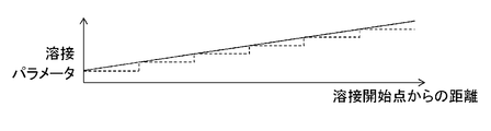
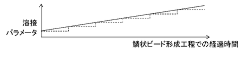
- At least one of the welding parameters changes continuously or stepwise in changing the welding conditions, in other words, a change waveform of the welding parameters with respect to, for example, the teaching position or the elapsed time It is possible to solve the above-mentioned problems by making the slope and the slope (hereinafter, this is also referred to as the slope of the welding parameter).
- FIG. 7A is a conceptual view of the teaching point position in the welding section according to the present embodiment
- FIG. 7B is the relation between the distance from the welding start point and the welding parameter
- FIG. 7C is the teaching point position and the welding parameter
- FIG. 7D shows the relationship between the elapsed time in the wedge-shaped bead forming process and the welding parameters, respectively.
- a plurality of teaching points are set at the time of teaching performed before welding.
- the torch is moved at a predetermined welding speed Vw along the traveling direction from the welding start point P1.
- the arc welding is started simultaneously with the start of the movement of the torch, and the base material 17 is welded to the welding end point Pn.
- the welding parameters may be changed continuously or stepwise according to the distance from the welding start point P1 in the welding section.
- the amount of change may be made different in the middle of the welding section, or the cycle to be changed may be made different in the middle of the welding section.
- the welding parameters may be changed continuously or stepwise according to the teaching point position.
- the welding parameter may be changed continuously or stepwise every time the teaching point position advances one by one as shown by the broken line in FIG. 7C.
- the welding parameter may be changed continuously or stepwise as the teaching point position advances by a plurality of points.
- the amount of change when the welding parameter is changed stepwise, the amount of change may be made different in the middle of the welding section, or the cycle to be changed may be made different in the middle of the welding section.
- the welding parameters in the wedge-shaped bead forming step, the welding parameters may be changed continuously or stepwise according to the elapsed time from the welding start time.
- the amount of change when the welding parameter is changed stepwise, the amount of change may be made different in the middle of the welding section, or the cycle to be changed may be made different in the middle of the welding section.
- At least one of the plurality of welding parameters may be continuous or stepped depending on either the elapsed time in the wedge bead forming process or the distance from the welding start point in the welding section or the welding teaching point position
- the heat input to the base material 17 changes, it is possible to change the ratio of the heat input by changing it so as to change it.
- the heat input amount with respect to the base material 17 can be adjusted appropriately, and a wedge-shaped bead can be made into a desired finished shape in a predetermined welding section.
- Table 3 shows the values of the respective welding parameters when one or more of the welding parameters are sloped.
- Condition A is an example of welding conditions for eliminating the shortage of heat input near the welding start point P1. If this heat input shortage occurs, the beads may have an extremely convex shape, or overlapping between the beads may occur, and the wrinkles of the wrinkled pattern may become unclear.
- the arc ON time T1 and the arc OFF time T3 are sloped with respect to the elapsed time in the wedge-shaped bead forming step. For example, the welding conditions are changed so as to take in a new slope condition every sampling time 100 msec from the welding start time.
- the heat input to the base material 17 is increased by setting the arc ON time T1 to 500 msec and the arc OFF time T3 to 30 msec. From this time point, the arc ON time T1 and the arc OFF time T3 are changed stepwise every 100 msec, and after 2 seconds, the arc ON time T1 is 300 msec and the arc OFF time T3 is 200 msec.
- Condition B is another example of welding conditions for eliminating the shortage of heat input near the welding start point P1.
- the arc ON time T1 is set longer and the arc OFF time T3 is set shorter.
- the arc ON time T1 is shortened, and the arc OFF time T3 is lengthened to change each to approach the initial conditions.
- the welding current I is reduced to be close to the initial condition.
- the condition C is an example of welding conditions in the case where the heat capacity of the base material 17 changes due to a change in the thickness of the base material 17 (see FIG. 9) or a change in shape in the welding section.
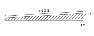
- the base material 17 is shaped so that the thickness is the thinnest at the point P1, the thickness increases along the direction of welding, and the thickness becomes constant at the point P2.
- the welding current I is increased continuously or stepwise.
- the heat capacity change of the base material 17 in the welding section can be compensated, and a desired finished shape can be obtained at the welding portion.
- the welding quality can be kept good.
- Condition D is an example of welding conditions for solving this problem.
- the welding current I is decreased continuously or stepwise depending on the distance from the welding start point P1.
- the shape of the base material 17 which is the object to be welded changes in the welding section, if welding is performed under certain conditions, a desired finished shape may not be obtained or the welding quality may be degraded. is there.
- FIG. 8 shows a schematic view of an example of the shape of the base material according to the present embodiment, and the base material 17 is a so-called wedge-shaped welded body.
- the shape changes continuously at the T-shaped joint portion which is a welding section.
- the condition E is an example of the condition for welding the joint portion of the base material 17 having the shape shown in FIG. 8, and as the welding progresses from the welding start point P1 to a predetermined distance (15 mm), the welding current I is continuous. It is intended to increase the number of By changing the welding conditions in this manner, a desired finished shape can be obtained in the base material 17 in which the shape in the welding section changes. In addition, the welding quality can be kept good.
- condition E if the welding parameter is sloped in a section from the welding start point P1 to a predetermined distance, the change rate of the slope, etc., even if a plurality of teaching points are located in the section. There is no sharp change before and after the teaching point.
- FIG. 9 shows a cross-sectional schematic view of another base material according to the present embodiment, in which the thickness of the base material 17 monotonously increases from the welding start point P1 to the end point P2 of the welding section.
- Table 4 has shown the value of each welding parameter at the time of making two or more of said three welding parameters slope.
- Condition F is an example of welding conditions for suppressing the occurrence of pits.
- the end active time T2 it is possible to reduce the number of pits generated in the scaly bead.
- the arc OFF time T3 is shortened as the end active time T2 is lengthened, and the heat input in the welding section shown in FIG. I try to keep my balance.
- the short circuit welding is performed to the base material 17 during the end active time T2
- the heat input to the base material 17 in this period is not zero. Therefore, if the arc OFF time T3 is shortened by a time equivalent to the extension of the end active time T2, the heat input to the base material 17 becomes excessive compared to the setting. Therefore, in this example, the arc OFF time T3 is shortened by an amount shorter than the extension time of the end active time T2.
- the welding speed Vw is constant, the pitch G changes so as to be gradually longer in the welding section.
- the condition G is another example of welding conditions for suppressing the occurrence of pits.
- the arc ON time T1 is also sloped in order to suppress the change of the pitch G.
- the number of pits generated in the wedge-shaped bead can be eliminated, and the appearance design of the wedge-shaped bead can be improved.
- the pitch G in the welding section can be made constant.
- FIG. 9 an example is shown in which the thickness of the base material 17 monotonously increases in the welding section, but the plates of the base material 17 are set to be replaced. The sign may be reversed as well. For example, in the case where the plate thickness is the thickest at the welding start point P1 and the plate thickness is the thinnest at the finish point P2, under condition F, the initial value of the end active time T2 is 60 msec and the finish value is 2 msec. The end active time T2 may be monotonously decreased.
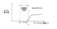
- FIG. 10 shows the relationship between the arc OFF time and the number of pits
- FIG. 11 shows the relationship between the end active time and the number of pits.
- the arc ON time T1 is constant
- the arc ON time T1 and the arc OFF time T3 are constant.
- the base material 17 is a 3.0 mm thick plate made of soft aluminum (A6061) and the surface of this plate is arc welded, the above time Tb is 120 msec to 170 msec, Ta is 120 msec, and Tc is It is about 240 msec.
- the range that the arc OFF time T3 can take is often narrow in order to achieve both suppression of pit generation and clarity of the ridge pattern. Therefore, even if this value is strictly set at the time of setting the initial condition, the initial condition may not be the optimum value depending on the shape of the base material 17 or the like.
- the value of the welding parameter including the arc OFF time T3 is sloped during arc welding, and welding is performed for each location such as a welding section or a teaching point. By changing and optimizing the conditions, it is possible to achieve both suppression of pit generation and clarity of the wrinkle pattern.
- the upper limit of the time during which pits are not generated in the wedge-shaped bead is Tb, but if pits are generated and the amount generated is an acceptable value in terms of welding strength or appearance, the time upper limit of the allowable range Tb1 (see FIG. 10) may be set as the variation allowable upper limit of the arc OFF time T3.
- the welding wire 18 is moved at a constant welding speed Vw in a predetermined welding section.
- the second short-circuit welding period Tse a process in which the welding wire 18 and the base material 17 are short-circuited to cool the base material 17 and an arc is generated between the welding wire 18 and the base material 17 The process of heating 17 is alternately repeated.
- the marks that the base material 17 has cooled and solidified may appear on the surface of the base material 17 at predetermined intervals.
- This mark is an appearance called "wrinkle". Since the amount of heat input in pulse welding performed prior to the second short circuit welding is large, such marks do not appear if the end active time T2 is short, but if the end active time T2 becomes long, the entrance to the base material 17 As the amount of heat decreases and the temperature of the base material 17 also decreases, wrinkles begin to appear. Since the occurrence of such wrinkles impairs the appearance of the scaly bead like pits and the like, it is necessary to make the end active time T2 shorter than the time Td so as not to cause the wrinkles.
- the range that the end active time T2 can take is often narrow in order to achieve both the suppression of pitting and the clarity of wrinkles. Therefore, even if this value is strictly set at the time of setting the initial condition, the initial condition may not be the optimum value depending on the shape of the base material 17 or the like.
- the value of the welding parameter including the end active time T2 is sloped during arc welding, and welding is performed at each location such as a welding section or teaching point. By changing and optimizing the conditions, it is possible to achieve both suppression of pit generation and clarity of the wrinkle pattern.
- the welding method of the present disclosure does not stop the movement of the torch during the arc ON period and the arc OFF period. This can increase the welding speed.
- the welding method of the present disclosure when the welding method of the present disclosure is applied to consumable electrode type arc welding, generation of spatter due to scattering of droplets of molten wire and the like can be suppressed.
- the welding method of the present disclosure can suppress the occurrence of blow holes and pits even when the base material is aluminum.
- the welding method of the present disclosure in a complex welding object in which the plate thickness and the work shape change in the middle, the appearance of the wedge-shaped bead is made the desired finished shape for each portion and welding defects are not generated. As such, welding conditions can be changed.
- the control method of arc welding according to the present disclosure can easily change the welding conditions and can make the wedge-shaped bead into a desired finished shape, so arc welding is applied to frames of bicycles, motorcycles, automobiles, etc. It is useful above.
- Input power supply 2 Main transformer (transformer) 3 Primary side rectification unit 4 Switching unit 5 DCL (reactor) 6 Secondary side rectification unit 7 Welding current detection unit 8 Welding voltage detection unit 9 Control switching unit 10 Output control unit 11 Short circuit welding control unit 12 Pulse welding control unit 13 Wire feeding speed control unit 14 Wire feeding speed detection unit 15 Calculation Part 16 arc welding apparatus 17 base material 18 welding wire 19 arc 20 welding tip 21 wire feeding part 22 welding condition setting part 23 short circuit welding setting part 24 pulse welding setting 25 cooling period setting part
Landscapes
- Engineering & Computer Science (AREA)
- Physics & Mathematics (AREA)
- Plasma & Fusion (AREA)
- Mechanical Engineering (AREA)
- Theoretical Computer Science (AREA)
- Arc Welding Control (AREA)
Abstract
La présente invention concerne un procédé de commande de soudage à l'arc, selon lequel une pluralité de cordons de soudure irréguliers disposés en continu sur un métal de base sont formés tout en prenant, en tant que période de soudage C, la somme d'une période MARCHE d'arc A, au cours de laquelle un courant de soudage I circule dans un fil de soudage, et une période ARRÊT d'arc B, au cours de laquelle un courant de soudage I ne circule pas. Le procédé de commande de soudage à l'arc comporte : une étape de réglage de condition initiale, destinée à régler une valeur initiale d'une condition de soudage dans laquelle un métal de base est soudé à l'arc; et une étape de formation de cordons de soudure irréguliers, destinée à former une pluralité de cordons de soudure irréguliers dans une zone de soudage prédéterminée du métal de base, tout en déplaçant le fil de soudage dans la zone de soudage prédéterminée du métal de base à une vitesse de soudage Vw. La condition de soudage comprend la période MARCHE d'arc A et la période ARRÊT d'arc B, et comprend en outre le courant de soudage I, la vitesse de soudage Vw et/ou un pas de cordon de soudure G. En outre, le procédé de commande de soudage à l'arc comporte une étape de modification de condition de soudage destinée à déterminer, sur la base d'une condition de finition prédéterminée destinée aux cordons de soudure irréguliers, s'il est nécessaire de modifier la valeur initiale, et à modifier au moins un paramètre parmi une pluralité de paramètres de soudage en vue de satisfaire une condition de finition prédéterminée.
Priority Applications (4)
| Application Number | Priority Date | Filing Date | Title |
|---|---|---|---|
| EP18901824.5A EP3744460B1 (fr) | 2018-01-24 | 2018-12-19 | Procédé de commande de soudage à l'arc |
| JP2019567916A JP7149467B2 (ja) | 2018-01-24 | 2018-12-19 | アーク溶接の制御方法 |
| CN201880056892.3A CN111093877B (zh) | 2018-01-24 | 2018-12-19 | 电弧焊接的控制方法 |
| US16/909,541 US12459046B2 (en) | 2018-01-24 | 2020-06-23 | Arc welding controlling method |
Applications Claiming Priority (2)
| Application Number | Priority Date | Filing Date | Title |
|---|---|---|---|
| JP2018009888 | 2018-01-24 | ||
| JP2018-009888 | 2018-01-24 |
Related Child Applications (1)
| Application Number | Title | Priority Date | Filing Date |
|---|---|---|---|
| US16/909,541 Continuation US12459046B2 (en) | 2018-01-24 | 2020-06-23 | Arc welding controlling method |
Publications (1)
| Publication Number | Publication Date |
|---|---|
| WO2019146318A1 true WO2019146318A1 (fr) | 2019-08-01 |
Family
ID=67395333
Family Applications (1)
| Application Number | Title | Priority Date | Filing Date |
|---|---|---|---|
| PCT/JP2018/046682 Ceased WO2019146318A1 (fr) | 2018-01-24 | 2018-12-19 | Procédé de commande de soudage à l'arc |
Country Status (5)
| Country | Link |
|---|---|
| US (1) | US12459046B2 (fr) |
| EP (1) | EP3744460B1 (fr) |
| JP (1) | JP7149467B2 (fr) |
| CN (1) | CN111093877B (fr) |
| WO (1) | WO2019146318A1 (fr) |
Cited By (2)
| Publication number | Priority date | Publication date | Assignee | Title |
|---|---|---|---|---|
| WO2023095623A1 (fr) * | 2021-11-29 | 2023-06-01 | パナソニックIpマネジメント株式会社 | Procédé de soudage à l'arc et dispositif de soudage à l'arc |
| WO2025220604A1 (fr) * | 2024-04-18 | 2025-10-23 | 株式会社ダイヘン | Système de moulage par stratification |
Families Citing this family (11)
| Publication number | Priority date | Publication date | Assignee | Title |
|---|---|---|---|---|
| EP3599046A1 (fr) * | 2018-07-27 | 2020-01-29 | FRONIUS INTERNATIONAL GmbH | Procédé de soudage à l'arc à l'aide d'un fil fusible de soudure |
| WO2020251038A1 (fr) * | 2019-06-14 | 2020-12-17 | パナソニックIpマネジメント株式会社 | Dispositif de commande de soudage de réparation et procédé de commande de soudage de réparation |
| EP3991901A4 (fr) * | 2019-06-28 | 2022-09-28 | Panasonic Intellectual Property Management Co., Ltd. | Système de soudage de réparation, procédé de soudage de réparation, dispositif d'inspection et dispositif de commande de robot |
| CN112828419A (zh) * | 2020-12-31 | 2021-05-25 | 唐山松下产业机器有限公司 | 形成鱼鳞纹焊缝的焊接控制方法、装置、介质和电子设备 |
| JP2022107350A (ja) * | 2021-01-08 | 2022-07-21 | 株式会社ダイヘン | 溶接ロボット |
| JP7491860B2 (ja) * | 2021-03-03 | 2024-05-28 | 株式会社神戸製鋼所 | エレクトロスラグ溶接またはエレクトロガス溶接の制御方法、制御装置、溶接システム、およびプログラム |
| CN114289830B (zh) * | 2021-12-30 | 2023-10-20 | 唐山松下产业机器有限公司 | 焊缝成型补偿方法及装置、存储介质及电子设备 |
| KR102828948B1 (ko) * | 2022-11-02 | 2025-07-03 | 한국광기술원 | 3차원 데이터 기반의 용접 상태 진단 장치 및 시스템 |
| EP4431215A1 (fr) | 2023-03-13 | 2024-09-18 | FRONIUS INTERNATIONAL GmbH | Procede d'assemblage d'intervalles de reglage |
| CN118123187B (zh) * | 2024-01-30 | 2025-09-05 | 山东奥太电气有限公司 | 一种熔化极气保焊引弧控制方法及系统 |
| CN119304315B (zh) * | 2024-11-29 | 2026-03-06 | 唐山松下产业机器有限公司 | 一种鱼鳞纹焊接控制方法 |
Citations (6)
| Publication number | Priority date | Publication date | Assignee | Title |
|---|---|---|---|---|
| JPH0655268A (ja) | 1992-08-10 | 1994-03-01 | Yamaha Shatai Kogyo Kk | 溶接ロボット |
| JP2008168321A (ja) * | 2007-01-11 | 2008-07-24 | Honda Motor Co Ltd | 溶接方法 |
| JP2009119477A (ja) * | 2007-11-12 | 2009-06-04 | Daihen Corp | ステッチパルス溶接装置 |
| JP2009154206A (ja) * | 2007-12-03 | 2009-07-16 | Daihen Corp | ステッチパルス溶接方法 |
| JP2011152545A (ja) * | 2009-12-17 | 2011-08-11 | Daihen Corp | アーク溶接方法 |
| WO2018043626A1 (fr) * | 2016-09-05 | 2018-03-08 | パナソニックIpマネジメント株式会社 | Procédé de commande de soudage à l'arc |
Family Cites Families (28)
| Publication number | Priority date | Publication date | Assignee | Title |
|---|---|---|---|---|
| JPS61202774A (ja) | 1985-03-06 | 1986-09-08 | Nippon Kokan Kk <Nkk> | 片面炭酸ガスア−ク溶接方法 |
| JPH01237077A (ja) | 1988-03-18 | 1989-09-21 | Suzuki Motor Co Ltd | Mig溶接における溶接制御方法 |
| JPH08155644A (ja) | 1994-12-02 | 1996-06-18 | Miyachi Technos Corp | アーク溶接モニタ装置 |
| JPH08257751A (ja) | 1995-03-24 | 1996-10-08 | Toshiba Corp | 自動溶接トーチ制御装置 |
| JP3768603B2 (ja) | 1995-12-11 | 2006-04-19 | 大陽日酸株式会社 | アーク溶接方法 |
| JPH106005A (ja) | 1996-06-24 | 1998-01-13 | Fanuc Ltd | アーク溶接方法 |
| ITMI20030589A1 (it) * | 2003-03-25 | 2004-09-26 | Danieli Off Mecc | Sistema e metodo per il controllo in linea di una macchina |
| JP2006130535A (ja) | 2004-11-08 | 2006-05-25 | Sansha Electric Mfg Co Ltd | 溶接方法および溶接用電源装置 |
| JP4995697B2 (ja) * | 2007-11-12 | 2012-08-08 | 株式会社ダイヘン | ステッチパルス溶接装置 |
| US10086461B2 (en) * | 2009-01-13 | 2018-10-02 | Lincoln Global, Inc. | Method and system to start and use combination filler wire feed and high intensity energy source for welding |
| JP5410220B2 (ja) * | 2009-09-29 | 2014-02-05 | 株式会社ダイヘン | アーク溶接方法およびアーク溶接システム |
| WO2012032703A1 (fr) * | 2010-09-10 | 2012-03-15 | パナソニック株式会社 | Procédé de commande de soudage à l'arc |
| JP2012061475A (ja) * | 2010-09-14 | 2012-03-29 | Daihen Corp | アーク溶接方法、溶接電源装置、およびアーク溶接システム |
| JP5758130B2 (ja) * | 2011-01-11 | 2015-08-05 | 株式会社ダイヘン | アーク溶接方法 |
| JP5808953B2 (ja) * | 2011-06-02 | 2015-11-10 | 株式会社ダイヘン | アーク溶接システムおよびアーク溶接方法 |
| US20130299476A1 (en) * | 2011-07-12 | 2013-11-14 | Panasonic Corporation | Arc welding control method and arc welding device |
| EP3342521B1 (fr) * | 2012-03-16 | 2019-08-21 | Panasonic Intellectual Property Management Co., Ltd. | Dispositif de soudage à l'arc |
| US9676051B2 (en) * | 2012-10-18 | 2017-06-13 | Lincoln Global, Inc. | System and methods providing modulation schemes for achieving a weld bead appearance |
| JP2014087818A (ja) | 2012-10-30 | 2014-05-15 | Panasonic Corp | アーク溶接方法およびアーク溶接装置 |
| US10315268B2 (en) | 2012-11-07 | 2019-06-11 | Lincoln Global, Inc. | Method and system to control heat input in a welding operation |
| US10543551B2 (en) | 2013-09-16 | 2020-01-28 | Illinois Tool Works Inc. | Synchronized rotating arc welding method and system |
| US20170036288A1 (en) * | 2013-11-04 | 2017-02-09 | Illinois Tool Works Inc. | Systems and methods for selecting weld parameters |
| EP3208024B1 (fr) | 2014-10-17 | 2020-01-29 | Panasonic Intellectual Property Management Co., Ltd. | Procédé de commande de soudage à l'arc |
| JP6596669B2 (ja) * | 2014-11-11 | 2019-10-30 | パナソニックIpマネジメント株式会社 | アーク溶接の制御方法 |
| US10610946B2 (en) * | 2015-12-07 | 2020-04-07 | Illinois Tool Works, Inc. | Systems and methods for automated root pass welding |
| US20170246701A1 (en) * | 2016-02-29 | 2017-08-31 | Lincoln Global, Inc. | System and method for welding using rotating consumable |
| CN108883486B (zh) * | 2016-03-29 | 2020-07-14 | 松下知识产权经营株式会社 | 电弧焊接控制方法 |
| US10730140B2 (en) * | 2017-08-29 | 2020-08-04 | Illinois Tool Works Inc. | Low energy, motion-assist, point-and-shoot welding torch |
-
2018
- 2018-12-19 WO PCT/JP2018/046682 patent/WO2019146318A1/fr not_active Ceased
- 2018-12-19 EP EP18901824.5A patent/EP3744460B1/fr active Active
- 2018-12-19 CN CN201880056892.3A patent/CN111093877B/zh active Active
- 2018-12-19 JP JP2019567916A patent/JP7149467B2/ja active Active
-
2020
- 2020-06-23 US US16/909,541 patent/US12459046B2/en active Active
Patent Citations (6)
| Publication number | Priority date | Publication date | Assignee | Title |
|---|---|---|---|---|
| JPH0655268A (ja) | 1992-08-10 | 1994-03-01 | Yamaha Shatai Kogyo Kk | 溶接ロボット |
| JP2008168321A (ja) * | 2007-01-11 | 2008-07-24 | Honda Motor Co Ltd | 溶接方法 |
| JP2009119477A (ja) * | 2007-11-12 | 2009-06-04 | Daihen Corp | ステッチパルス溶接装置 |
| JP2009154206A (ja) * | 2007-12-03 | 2009-07-16 | Daihen Corp | ステッチパルス溶接方法 |
| JP2011152545A (ja) * | 2009-12-17 | 2011-08-11 | Daihen Corp | アーク溶接方法 |
| WO2018043626A1 (fr) * | 2016-09-05 | 2018-03-08 | パナソニックIpマネジメント株式会社 | Procédé de commande de soudage à l'arc |
Non-Patent Citations (1)
| Title |
|---|
| See also references of EP3744460A4 |
Cited By (2)
| Publication number | Priority date | Publication date | Assignee | Title |
|---|---|---|---|---|
| WO2023095623A1 (fr) * | 2021-11-29 | 2023-06-01 | パナソニックIpマネジメント株式会社 | Procédé de soudage à l'arc et dispositif de soudage à l'arc |
| WO2025220604A1 (fr) * | 2024-04-18 | 2025-10-23 | 株式会社ダイヘン | Système de moulage par stratification |
Also Published As
| Publication number | Publication date |
|---|---|
| US20200316703A1 (en) | 2020-10-08 |
| EP3744460B1 (fr) | 2024-04-03 |
| CN111093877A (zh) | 2020-05-01 |
| EP3744460A1 (fr) | 2020-12-02 |
| EP3744460A4 (fr) | 2021-04-07 |
| JP7149467B2 (ja) | 2022-10-07 |
| CN111093877B (zh) | 2021-12-21 |
| JPWO2019146318A1 (ja) | 2021-01-14 |
| US12459046B2 (en) | 2025-11-04 |
Similar Documents
| Publication | Publication Date | Title |
|---|---|---|
| JP7149467B2 (ja) | アーク溶接の制御方法 | |
| JP5292459B2 (ja) | 短絡アーク溶接プロセスの間に溶接入熱を増加する方法及びシステム | |
| US8937267B2 (en) | Method and system to increase heat input to a weld during a short-circuit arc welding process | |
| JP3809983B2 (ja) | 消耗電極式の交流ガスシールド溶接装置 | |
| JP7041034B2 (ja) | 溶接電源、溶接システム、溶接電源の制御方法及びプログラム | |
| CN113165095B (zh) | 电弧焊接控制方法 | |
| JPWO2018043626A1 (ja) | アーク溶接制御方法 | |
| KR102826171B1 (ko) | 용접 제어 방법, 용접 제어 장치, 용접 전원, 용접 시스템, 프로그램, 용접 방법 및 부가 제조 방법 | |
| JP7113329B2 (ja) | アーク溶接制御方法 | |
| JP7407398B2 (ja) | アーク溶接の制御方法 | |
| WO2023223739A1 (fr) | Procédé de régulation de forme de cordon de soudure, procédé de commande de source d'alimentation électrique, procédé de fabrication additive, dispositif de commande, dispositif de source d'alimentation électrique, système de soudage et système et programme de fabrication additive | |
| KR20210061206A (ko) | 일렉트로 가스 용접 장치 및 그의 입열량 제어방법 | |
| US20250319540A1 (en) | Method for controlling gas metal arc welding, method for setting welding condition, welding control device, welding power supply, welding system, program, gas metal arc welding method, and additive manufacturing method | |
| CN114728362B (zh) | 气体保护电弧焊接的输出控制方法、焊接系统、焊接电源以及焊接控制装置 | |
| JP7428596B2 (ja) | レーザ・アークハイブリッド溶接装置 | |
| JP4646483B2 (ja) | 消耗電極式アークスポット溶接方法および消耗電極式アーク溶接装置 | |
| JPH10175067A (ja) | セルフシールドアーク溶接方法 | |
| KR20260023484A (ko) | 긴 스틱 아웃 서브머지드 아크 용접을 위한 아크-개시 공정 | |
| CN119562875A (zh) | 电弧焊接方法 | |
| JP2025160739A (ja) | アーク溶接方法 | |
| WO2025220625A1 (fr) | Procédé de soudage à l'arc en courant alternatif | |
| JPH03297561A (ja) | 消耗電極式交流ガスシールドアーク溶接方法および装置 |
Legal Events
| Date | Code | Title | Description |
|---|---|---|---|
| 121 | Ep: the epo has been informed by wipo that ep was designated in this application |
Ref document number: 18901824 Country of ref document: EP Kind code of ref document: A1 |
|
| ENP | Entry into the national phase |
Ref document number: 2019567916 Country of ref document: JP Kind code of ref document: A |
|
| NENP | Non-entry into the national phase |
Ref country code: DE |
|
| ENP | Entry into the national phase |
Ref document number: 2018901824 Country of ref document: EP Effective date: 20200824 |