EP4003460B1 - Dispositif d'application de fluide - Google Patents
Dispositif d'application de fluide Download PDFInfo
- Publication number
- EP4003460B1 EP4003460B1 EP20739646.6A EP20739646A EP4003460B1 EP 4003460 B1 EP4003460 B1 EP 4003460B1 EP 20739646 A EP20739646 A EP 20739646A EP 4003460 B1 EP4003460 B1 EP 4003460B1
- Authority
- EP
- European Patent Office
- Prior art keywords
- procedure
- tensioning
- piston
- dispensing
- frequency
- Prior art date
- Legal status (The legal status is an assumption and is not a legal conclusion. Google has not performed a legal analysis and makes no representation as to the accuracy of the status listed.)
- Active
Links
Images


Classifications
-
- A—HUMAN NECESSITIES
- A61—MEDICAL OR VETERINARY SCIENCE; HYGIENE
- A61D—VETERINARY INSTRUMENTS, IMPLEMENTS, TOOLS, OR METHODS
- A61D1/00—Surgical instruments for veterinary use
- A61D1/02—Trocars or cannulas for teats; Vaccination appliances
- A61D1/025—Vaccination appliances
-
- A—HUMAN NECESSITIES
- A61—MEDICAL OR VETERINARY SCIENCE; HYGIENE
- A61D—VETERINARY INSTRUMENTS, IMPLEMENTS, TOOLS, OR METHODS
- A61D7/00—Devices or methods for introducing solid, liquid, or gaseous remedies or other materials into or onto the bodies of animals
-
- A—HUMAN NECESSITIES
- A61—MEDICAL OR VETERINARY SCIENCE; HYGIENE
- A61M—DEVICES FOR INTRODUCING MEDIA INTO, OR ONTO, THE BODY; DEVICES FOR TRANSDUCING BODY MEDIA OR FOR TAKING MEDIA FROM THE BODY; DEVICES FOR PRODUCING OR ENDING SLEEP OR STUPOR
- A61M5/00—Devices for bringing media into the body in a subcutaneous, intra-vascular or intramuscular way; Accessories therefor, e.g. filling or cleaning devices, arm-rests
- A61M5/178—Syringes
- A61M5/20—Automatic syringes, e.g. with automatically actuated piston rod, with automatic needle injection, filling automatically
- A61M5/204—Automatic syringes, e.g. with automatically actuated piston rod, with automatic needle injection, filling automatically connected to external reservoirs for multiple refilling
-
- A—HUMAN NECESSITIES
- A61—MEDICAL OR VETERINARY SCIENCE; HYGIENE
- A61M—DEVICES FOR INTRODUCING MEDIA INTO, OR ONTO, THE BODY; DEVICES FOR TRANSDUCING BODY MEDIA OR FOR TAKING MEDIA FROM THE BODY; DEVICES FOR PRODUCING OR ENDING SLEEP OR STUPOR
- A61M5/00—Devices for bringing media into the body in a subcutaneous, intra-vascular or intramuscular way; Accessories therefor, e.g. filling or cleaning devices, arm-rests
- A61M5/178—Syringes
- A61M5/30—Syringes for injection by jet action, without needle, e.g. for use with replaceable ampoules or carpules
-
- A—HUMAN NECESSITIES
- A61—MEDICAL OR VETERINARY SCIENCE; HYGIENE
- A61M—DEVICES FOR INTRODUCING MEDIA INTO, OR ONTO, THE BODY; DEVICES FOR TRANSDUCING BODY MEDIA OR FOR TAKING MEDIA FROM THE BODY; DEVICES FOR PRODUCING OR ENDING SLEEP OR STUPOR
- A61M5/00—Devices for bringing media into the body in a subcutaneous, intra-vascular or intramuscular way; Accessories therefor, e.g. filling or cleaning devices, arm-rests
- A61M5/178—Syringes
- A61M5/31—Details
- A61M5/3148—Means for causing or aiding aspiration or plunger retraction
-
- A—HUMAN NECESSITIES
- A61—MEDICAL OR VETERINARY SCIENCE; HYGIENE
- A61M—DEVICES FOR INTRODUCING MEDIA INTO, OR ONTO, THE BODY; DEVICES FOR TRANSDUCING BODY MEDIA OR FOR TAKING MEDIA FROM THE BODY; DEVICES FOR PRODUCING OR ENDING SLEEP OR STUPOR
- A61M5/00—Devices for bringing media into the body in a subcutaneous, intra-vascular or intramuscular way; Accessories therefor, e.g. filling or cleaning devices, arm-rests
- A61M5/178—Syringes
- A61M5/31—Details
- A61M5/315—Pistons; Piston-rods; Guiding, blocking or restricting the movement of the rod or piston; Appliances on the rod for facilitating dosing ; Dosing mechanisms
- A61M5/31525—Dosing
- A61M5/3153—Dosing by single stroke limiting means
-
- A—HUMAN NECESSITIES
- A61—MEDICAL OR VETERINARY SCIENCE; HYGIENE
- A61M—DEVICES FOR INTRODUCING MEDIA INTO, OR ONTO, THE BODY; DEVICES FOR TRANSDUCING BODY MEDIA OR FOR TAKING MEDIA FROM THE BODY; DEVICES FOR PRODUCING OR ENDING SLEEP OR STUPOR
- A61M5/00—Devices for bringing media into the body in a subcutaneous, intra-vascular or intramuscular way; Accessories therefor, e.g. filling or cleaning devices, arm-rests
- A61M5/178—Syringes
- A61M5/31—Details
- A61M5/315—Pistons; Piston-rods; Guiding, blocking or restricting the movement of the rod or piston; Appliances on the rod for facilitating dosing ; Dosing mechanisms
- A61M5/31533—Dosing mechanisms, i.e. setting a dose
- A61M5/31545—Setting modes for dosing
- A61M5/31548—Mechanically operated dose setting member
-
- A—HUMAN NECESSITIES
- A61—MEDICAL OR VETERINARY SCIENCE; HYGIENE
- A61M—DEVICES FOR INTRODUCING MEDIA INTO, OR ONTO, THE BODY; DEVICES FOR TRANSDUCING BODY MEDIA OR FOR TAKING MEDIA FROM THE BODY; DEVICES FOR PRODUCING OR ENDING SLEEP OR STUPOR
- A61M5/00—Devices for bringing media into the body in a subcutaneous, intra-vascular or intramuscular way; Accessories therefor, e.g. filling or cleaning devices, arm-rests
- A61M5/178—Syringes
- A61M5/31—Details
- A61M5/315—Pistons; Piston-rods; Guiding, blocking or restricting the movement of the rod or piston; Appliances on the rod for facilitating dosing ; Dosing mechanisms
- A61M5/31565—Administration mechanisms, i.e. constructional features, modes of administering a dose
- A61M5/31576—Constructional features or modes of drive mechanisms for piston rods
-
- A—HUMAN NECESSITIES
- A61—MEDICAL OR VETERINARY SCIENCE; HYGIENE
- A61M—DEVICES FOR INTRODUCING MEDIA INTO, OR ONTO, THE BODY; DEVICES FOR TRANSDUCING BODY MEDIA OR FOR TAKING MEDIA FROM THE BODY; DEVICES FOR PRODUCING OR ENDING SLEEP OR STUPOR
- A61M5/00—Devices for bringing media into the body in a subcutaneous, intra-vascular or intramuscular way; Accessories therefor, e.g. filling or cleaning devices, arm-rests
- A61M5/178—Syringes
- A61M5/31—Details
- A61M5/315—Pistons; Piston-rods; Guiding, blocking or restricting the movement of the rod or piston; Appliances on the rod for facilitating dosing ; Dosing mechanisms
- A61M5/31565—Administration mechanisms, i.e. constructional features, modes of administering a dose
- A61M5/3159—Dose expelling manners
- A61M5/31593—Multi-dose, i.e. individually set dose repeatedly administered from the same medicament reservoir
-
- A—HUMAN NECESSITIES
- A61—MEDICAL OR VETERINARY SCIENCE; HYGIENE
- A61M—DEVICES FOR INTRODUCING MEDIA INTO, OR ONTO, THE BODY; DEVICES FOR TRANSDUCING BODY MEDIA OR FOR TAKING MEDIA FROM THE BODY; DEVICES FOR PRODUCING OR ENDING SLEEP OR STUPOR
- A61M5/00—Devices for bringing media into the body in a subcutaneous, intra-vascular or intramuscular way; Accessories therefor, e.g. filling or cleaning devices, arm-rests
- A61M5/36—Devices for bringing media into the body in a subcutaneous, intra-vascular or intramuscular way; Accessories therefor, e.g. filling or cleaning devices, arm-rests with means for eliminating or preventing injection or infusion of air into body
- A61M5/365—Air detectors
-
- A—HUMAN NECESSITIES
- A61—MEDICAL OR VETERINARY SCIENCE; HYGIENE
- A61M—DEVICES FOR INTRODUCING MEDIA INTO, OR ONTO, THE BODY; DEVICES FOR TRANSDUCING BODY MEDIA OR FOR TAKING MEDIA FROM THE BODY; DEVICES FOR PRODUCING OR ENDING SLEEP OR STUPOR
- A61M5/00—Devices for bringing media into the body in a subcutaneous, intra-vascular or intramuscular way; Accessories therefor, e.g. filling or cleaning devices, arm-rests
- A61M5/178—Syringes
- A61M5/20—Automatic syringes, e.g. with automatically actuated piston rod, with automatic needle injection, filling automatically
- A61M2005/2006—Having specific accessories
- A61M2005/202—Having specific accessories cocking means, e.g. to bias the main drive spring of an injector
-
- A—HUMAN NECESSITIES
- A61—MEDICAL OR VETERINARY SCIENCE; HYGIENE
- A61M—DEVICES FOR INTRODUCING MEDIA INTO, OR ONTO, THE BODY; DEVICES FOR TRANSDUCING BODY MEDIA OR FOR TAKING MEDIA FROM THE BODY; DEVICES FOR PRODUCING OR ENDING SLEEP OR STUPOR
- A61M5/00—Devices for bringing media into the body in a subcutaneous, intra-vascular or intramuscular way; Accessories therefor, e.g. filling or cleaning devices, arm-rests
- A61M5/178—Syringes
- A61M5/31—Details
- A61M2005/3114—Filling or refilling
- A61M2005/3115—Filling or refilling spring-assisted
-
- A—HUMAN NECESSITIES
- A61—MEDICAL OR VETERINARY SCIENCE; HYGIENE
- A61M—DEVICES FOR INTRODUCING MEDIA INTO, OR ONTO, THE BODY; DEVICES FOR TRANSDUCING BODY MEDIA OR FOR TAKING MEDIA FROM THE BODY; DEVICES FOR PRODUCING OR ENDING SLEEP OR STUPOR
- A61M5/00—Devices for bringing media into the body in a subcutaneous, intra-vascular or intramuscular way; Accessories therefor, e.g. filling or cleaning devices, arm-rests
- A61M5/178—Syringes
- A61M5/31—Details
- A61M2005/3128—Incorporating one-way valves, e.g. pressure-relief or non-return valves
-
- A—HUMAN NECESSITIES
- A61—MEDICAL OR VETERINARY SCIENCE; HYGIENE
- A61M—DEVICES FOR INTRODUCING MEDIA INTO, OR ONTO, THE BODY; DEVICES FOR TRANSDUCING BODY MEDIA OR FOR TAKING MEDIA FROM THE BODY; DEVICES FOR PRODUCING OR ENDING SLEEP OR STUPOR
- A61M5/00—Devices for bringing media into the body in a subcutaneous, intra-vascular or intramuscular way; Accessories therefor, e.g. filling or cleaning devices, arm-rests
- A61M5/178—Syringes
- A61M5/31—Details
- A61M5/315—Pistons; Piston-rods; Guiding, blocking or restricting the movement of the rod or piston; Appliances on the rod for facilitating dosing ; Dosing mechanisms
- A61M5/31565—Administration mechanisms, i.e. constructional features, modes of administering a dose
- A61M5/31576—Constructional features or modes of drive mechanisms for piston rods
- A61M2005/31588—Constructional features or modes of drive mechanisms for piston rods electrically driven
-
- A—HUMAN NECESSITIES
- A61—MEDICAL OR VETERINARY SCIENCE; HYGIENE
- A61M—DEVICES FOR INTRODUCING MEDIA INTO, OR ONTO, THE BODY; DEVICES FOR TRANSDUCING BODY MEDIA OR FOR TAKING MEDIA FROM THE BODY; DEVICES FOR PRODUCING OR ENDING SLEEP OR STUPOR
- A61M2205/00—General characteristics of the apparatus
- A61M2205/33—Controlling, regulating or measuring
- A61M2205/3317—Electromagnetic, inductive or dielectric measuring means
-
- A—HUMAN NECESSITIES
- A61—MEDICAL OR VETERINARY SCIENCE; HYGIENE
- A61M—DEVICES FOR INTRODUCING MEDIA INTO, OR ONTO, THE BODY; DEVICES FOR TRANSDUCING BODY MEDIA OR FOR TAKING MEDIA FROM THE BODY; DEVICES FOR PRODUCING OR ENDING SLEEP OR STUPOR
- A61M2205/00—General characteristics of the apparatus
- A61M2205/33—Controlling, regulating or measuring
- A61M2205/332—Force measuring means
-
- A—HUMAN NECESSITIES
- A61—MEDICAL OR VETERINARY SCIENCE; HYGIENE
- A61M—DEVICES FOR INTRODUCING MEDIA INTO, OR ONTO, THE BODY; DEVICES FOR TRANSDUCING BODY MEDIA OR FOR TAKING MEDIA FROM THE BODY; DEVICES FOR PRODUCING OR ENDING SLEEP OR STUPOR
- A61M2205/00—General characteristics of the apparatus
- A61M2205/33—Controlling, regulating or measuring
- A61M2205/3327—Measuring
-
- A—HUMAN NECESSITIES
- A61—MEDICAL OR VETERINARY SCIENCE; HYGIENE
- A61M—DEVICES FOR INTRODUCING MEDIA INTO, OR ONTO, THE BODY; DEVICES FOR TRANSDUCING BODY MEDIA OR FOR TAKING MEDIA FROM THE BODY; DEVICES FOR PRODUCING OR ENDING SLEEP OR STUPOR
- A61M2205/00—General characteristics of the apparatus
- A61M2205/33—Controlling, regulating or measuring
- A61M2205/3365—Rotational speed
-
- A—HUMAN NECESSITIES
- A61—MEDICAL OR VETERINARY SCIENCE; HYGIENE
- A61M—DEVICES FOR INTRODUCING MEDIA INTO, OR ONTO, THE BODY; DEVICES FOR TRANSDUCING BODY MEDIA OR FOR TAKING MEDIA FROM THE BODY; DEVICES FOR PRODUCING OR ENDING SLEEP OR STUPOR
- A61M2205/00—General characteristics of the apparatus
- A61M2205/33—Controlling, regulating or measuring
- A61M2205/3375—Acoustical, e.g. ultrasonic, measuring means
-
- A—HUMAN NECESSITIES
- A61—MEDICAL OR VETERINARY SCIENCE; HYGIENE
- A61M—DEVICES FOR INTRODUCING MEDIA INTO, OR ONTO, THE BODY; DEVICES FOR TRANSDUCING BODY MEDIA OR FOR TAKING MEDIA FROM THE BODY; DEVICES FOR PRODUCING OR ENDING SLEEP OR STUPOR
- A61M2205/00—General characteristics of the apparatus
- A61M2205/33—Controlling, regulating or measuring
- A61M2205/3379—Masses, volumes, levels of fluids in reservoirs, flow rates
-
- A—HUMAN NECESSITIES
- A61—MEDICAL OR VETERINARY SCIENCE; HYGIENE
- A61M—DEVICES FOR INTRODUCING MEDIA INTO, OR ONTO, THE BODY; DEVICES FOR TRANSDUCING BODY MEDIA OR FOR TAKING MEDIA FROM THE BODY; DEVICES FOR PRODUCING OR ENDING SLEEP OR STUPOR
- A61M2205/00—General characteristics of the apparatus
- A61M2205/58—Means for facilitating use, e.g. by people with impaired vision
- A61M2205/581—Means for facilitating use, e.g. by people with impaired vision by audible feedback
-
- A—HUMAN NECESSITIES
- A61—MEDICAL OR VETERINARY SCIENCE; HYGIENE
- A61M—DEVICES FOR INTRODUCING MEDIA INTO, OR ONTO, THE BODY; DEVICES FOR TRANSDUCING BODY MEDIA OR FOR TAKING MEDIA FROM THE BODY; DEVICES FOR PRODUCING OR ENDING SLEEP OR STUPOR
- A61M2205/00—General characteristics of the apparatus
- A61M2205/58—Means for facilitating use, e.g. by people with impaired vision
- A61M2205/582—Means for facilitating use, e.g. by people with impaired vision by tactile feedback
-
- A—HUMAN NECESSITIES
- A61—MEDICAL OR VETERINARY SCIENCE; HYGIENE
- A61M—DEVICES FOR INTRODUCING MEDIA INTO, OR ONTO, THE BODY; DEVICES FOR TRANSDUCING BODY MEDIA OR FOR TAKING MEDIA FROM THE BODY; DEVICES FOR PRODUCING OR ENDING SLEEP OR STUPOR
- A61M2205/00—General characteristics of the apparatus
- A61M2205/58—Means for facilitating use, e.g. by people with impaired vision
- A61M2205/583—Means for facilitating use, e.g. by people with impaired vision by visual feedback
- A61M2205/584—Means for facilitating use, e.g. by people with impaired vision by visual feedback having a color code
-
- A—HUMAN NECESSITIES
- A61—MEDICAL OR VETERINARY SCIENCE; HYGIENE
- A61M—DEVICES FOR INTRODUCING MEDIA INTO, OR ONTO, THE BODY; DEVICES FOR TRANSDUCING BODY MEDIA OR FOR TAKING MEDIA FROM THE BODY; DEVICES FOR PRODUCING OR ENDING SLEEP OR STUPOR
- A61M2205/00—General characteristics of the apparatus
- A61M2205/82—Internal energy supply devices
- A61M2205/8206—Internal energy supply devices battery-operated
-
- A—HUMAN NECESSITIES
- A61—MEDICAL OR VETERINARY SCIENCE; HYGIENE
- A61M—DEVICES FOR INTRODUCING MEDIA INTO, OR ONTO, THE BODY; DEVICES FOR TRANSDUCING BODY MEDIA OR FOR TAKING MEDIA FROM THE BODY; DEVICES FOR PRODUCING OR ENDING SLEEP OR STUPOR
- A61M5/00—Devices for bringing media into the body in a subcutaneous, intra-vascular or intramuscular way; Accessories therefor, e.g. filling or cleaning devices, arm-rests
- A61M5/178—Syringes
- A61M5/31—Details
- A61M5/315—Pistons; Piston-rods; Guiding, blocking or restricting the movement of the rod or piston; Appliances on the rod for facilitating dosing ; Dosing mechanisms
- A61M5/31525—Dosing
- A61M5/31528—Dosing by means of rotational movements, e.g. screw-thread mechanisms
Definitions
- the present invention relates to a device for administering a fluid having the features of the preamble of claim 1, which can be designed, for example, as a needle-free self-filling syringe with which a liquid medication, a liquid drug, a liquid vaccine or the like can be administered intramuscularly to animals.
- Such a device for applying a fluid should on the one hand be as light as possible and thus be portable for a long time with one hand by a user and at the same time enable the desired needle-free intramuscular injection.
- the object of the invention is therefore to provide such a device for applying a fluid.
- the device according to the invention for applying a fluid comprises a cylinder having an open discharge end, a piston displaceable within the cylinder between a front and rear end position, the piston being connected to a piston rod extending in a first direction beyond a rear end of the cylinder opposite the open discharge end, a check valve closing the open discharge end (acting as an outlet valve), and a clamping device connected to the piston rod.
- the clamping device can move the piston rod in a clamping process along the first direction until the piston is in its rear end position, thereby filling the cylinder with the fluid to be applied and preloading the piston rod toward the open discharge end.
- the device can have a connection opening into the cylinder.
- a hose or a container containing the fluid to be applied can be attached to the connection and secured for use of the device.
- the connection can have a check valve designed as an inlet valve and opens during the clamping process and closes when the fluid is applied. Accordingly, the outlet valve closes during the clamping process and opens when the fluid is applied.
- the clamping device can further, when the piston is in its rear end position, release the piston rod in a dispensing process, so that the piston moves counter to the first direction towards the open dispensing end due to the applied preload and fluid is dispensed in the cylinder via the check valve for application.
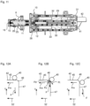
- the clamping device has a ramp that can be rotated by means of a motor and has a ramp path that extends along a helical line.
- the ramp path rises from a first plateau along an incline to a second plateau and falls from the second plateau via a step flank to the first plateau.
- the ramp path has a transition region that connects the second plateau and the step flank.
- the clamping device also has a roller that contacts the ramp path and is rotatably mounted in a driver that is connected to the piston rod, so that when the ramp rotates in a first direction of rotation, the ramp path passes under the roller that is thereby rotating.
- the clutch may comprise a first clutch part connected to the motor and a second clutch part connected to the ramp.
- One of the two clutch parts may comprise a protruding engagement element and the other of the two clutch parts may comprise a Recess into which the engagement element projects.
- the extent of the engagement element in the first direction of rotation can be smaller than the extent of the recess in the first direction of rotation by at least the rotational angle range covering the transition region. Thus, the extent of the recess in the first direction of rotation is greater than the extent of the engagement element in the first direction of rotation, thereby providing the desired freewheel.
- the coil springs can be designed as compression springs.
- a temporal target curve of the current consumption with a lower limit and an upper limit can be specified as the at least one default value, wherein the control unit
- the clamping process is determined to be in accordance with the intended purpose if the measured current consumption during the entire clamping process is not less than the lower limit and not greater than the upper limit.
- a desired temporal progression of the acceleration with an upper limit can be specified as the at least one preset value, wherein the control unit determines the dispensing process as intended if the measured acceleration during the entire dispensing process is not greater than the upper limit.
- a first upper and a first lower target frequency and/or a first upper and a first lower target amplitude can be specified as the at least one default value, wherein the control unit determines the delivery process as intended if a main frequency of the measured frequency spectrum lies between the first upper and the first lower target frequency and/or the amplitude of the main frequency of the measured frequency spectrum lies between the first upper and the first lower target amplitude.
- the main frequency here refers specifically to the frequency of the measured frequency spectrum that has the largest amplitude.
- the main frequency is usually the frequency that determines the pitch.
- the first upper target frequency may be 0.5%, 1%, 1.5%, 2%, 2.5%, 3%, 3.5%, 4%, 4.5%, 5%, 6%, 7%, 8%, 9%, 10%, 12%, 14%, or 15% higher than a predefined first target main frequency.
- the first lower target frequency may be 0.5%, 1%, 1.5%, 2%, 2.5%, 3%, 3.5%, 4%, 4.5%, 5%, 6%, 7%, 8%, 9%, 10%, 12%, 14%, or 15% lower than the predefined first target main frequency.
- the first upper target amplitude can be 0.5%, 1%, 1.5%, 2%, 2.5%, 3%, 3.5%, 4%, 4.5%, 5%, 6%, 7%, 8%, 9%, 10%, 12%, 14%, or 15% greater than a predefined first target main amplitude.
- the first lower target amplitude can be 0.5%, 1%, 1.5%, 2%, 2.5%, 3%, 3.5%, 4%, 4.5%, 5%, 6%, 7%, 8%, 9%, 10%, 12%, 14%, or 15% smaller than the predefined first target main amplitude.
- a second upper and a second lower target frequency and/or a second upper and a second lower target amplitude can be specified as the at least one default value, wherein the control unit determines the delivery process as intended if a first secondary frequency of the measured frequency spectrum lies between the second upper and the second lower target frequency and/or the amplitude of the first secondary frequency of the measured frequency spectrum lies between the second upper and the second lower target amplitude.
- the first secondary frequency is understood here in particular to be the frequency of the measured frequency spectrum which has the second highest amplitude and thus the largest amplitude after the main frequency.
- the second upper target frequency may be 0.5%, 1%, 1.5%, 2%, 2.5%, 3%, 3.5%, 4%, 4.5%, 5%, 6%, 7%, 8%, 9%, 10%, 12%, 14%, or 15% higher than a predefined first target secondary frequency.
- the second lower target frequency may be 0.5%, 1%, 1.5%, 2%, 2.5%, 3%, 3.5%, 4%, 4.5%, 5%, 6%, 7%, 8%, 9%, 10%, 12%, 14%, or 15% lower than the predefined first target secondary frequency.
- the second upper target amplitude can be 0.5%, 1%, 1.5%, 2%, 2.5%, 3%, 3.5%, 4%, 4.5%, 5%, 6%, 7%, 8%, 9%, 10%, 12%, 14%, or 15% greater than a predefined first target secondary amplitude.
- the second lower target amplitude can be 0.5%, 1%, 1.5%, 2%, 2.5%, 3%, 3.5%, 4%, 4.5%, 5%, 6%, 7%, 8%, 9%, 10%, 12%, 14%, or 15% smaller than the predefined first target secondary amplitude.
- a second, third, fourth, fifth and/or further secondary frequencies (whose amplitudes are each smaller) can be measured and taken into account in the same way to evaluate the delivery process.
- the delivery process is determined to be as intended if the main frequency of the measured frequency spectrum is lower than the target frequency and/or the amplitude of the main frequency of the measured frequency spectrum is higher than the target amplitude.
- the main frequency is understood here in particular to be the frequency of the measured frequency spectrum with the largest amplitude.
- the main frequency is usually the frequency that determines the pitch.
- the duration of the clamping process can be measured as a parameter.
- a second target time period can be specified as a default value, whereby the control unit determines the clamping process as intended if the measured time period is less than the second target time period.
- the angle of rotation swept along the first direction of rotation during the clamping process can be measured as a characteristic value.
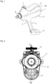
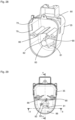
- the handle section 4 merges into a foot 8, in which, for example, a power supply (for example a battery) for the device 1 can be contained.
- a power supply for example a battery
- the device 1 according to the invention which can also be referred to as an application device 1, is designed in the embodiment described here for the needleless application of the fluid to an animal.
- the application preferably involves an intramuscular injection of the fluid, which can be, for example, a drug, a vaccine, or the like.
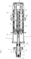
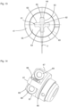
- the application device 1 has a cylinder-piston arrangement 10 ( Fig. 3 and 4 ) and is designed as a self-filling type in such a way that by a piston movement towards the dispensing area 6, the fluid is ejected and by an opposite movement of the piston, the cylinder is filled with the fluid for the next ejection process.
- the entire cylinder-piston assembly 10 is shown without the housing 2.
- the cylinder-piston assembly 10 comprises a front part 11 and a rear part 12 connected thereto.
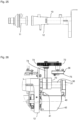
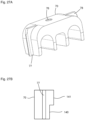
- the front part 11 comprises a cylinder 13 for receiving the fluid, which has an open discharge end 14 in which a check valve 15 is seated, which is in fluid communication with a nozzle 16.
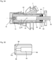
- the check valve 15 is also clearly visible in the illustration according to Fig. 34 and is designed to allow the fluid to be discharged from the cylinder 13 via the check valve 15 and the nozzle 16. Suction of air or liquid via the nozzle and the check valve 15 is not possible. In this direction, the check valve 15 closes.
- the front part 11 also has a connection 7 in which a further check valve 20 ( Fig. 3 ) that allows fluid communication from port 7 to cylinder 13 and blocks fluid communication in the opposite direction.
- Port 7 has a channel 21 that opens into cylinder 13 via several radial bores 22.
- the further check valve 20 can thus be referred to as an inlet valve and the check valve 15 can be referred to as an outlet valve.
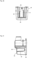
- the rear end 27 pointing away from the open discharge end 14 (well in Fig. 37 can be seen) of the piston rod 25 is connected via a plate 28 to a first guide rod 29 and a second guide rod 30, which extend parallel to each other and parallel to the piston rod 25 and which are guided in the rear part 12 ( Fig. 4 ).
- the ends of the guide rods 29 and 30 pointing away from the plate 28 are connected to a driver 31.
- a compression spring 32, 33 (e.g. coil spring) is arranged, the front ends of which each rest on the plate 28 and the rear ends of which each rest on a stop 34 of the rear part 12.
- the springs 32, 33 are tensioned.
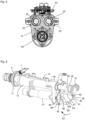
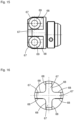
- a cover 35 and a metering adjustment device 36 are provided, which in the isometric view of the cylinder-piston arrangement 10 according to Fig. 6 are not shown, so that the driver 31 is clearly visible.
- the driver 31 has a rotatably mounted roller 40, wherein the axis of rotation of the roller 40 extends substantially perpendicular to the longitudinal axis of the piston rod 25.
- the roller 40 runs on a ramp track 41 of a ramp 42 rotating beneath the roller 40, wherein the ramp track 41 has a single turn, as in particular Fig. 6 to 8 can be seen.
- the plate 28, the springs 32, 33 including guide rods 29, 30, the driver 31 with roller 40, the ramp 42 together with the motor 51 and coupling 50 form a clamping device S for clamping the cylinder-piston arrangement 10.
Landscapes
- Health & Medical Sciences (AREA)
- Life Sciences & Earth Sciences (AREA)
- Veterinary Medicine (AREA)
- Engineering & Computer Science (AREA)
- Public Health (AREA)
- General Health & Medical Sciences (AREA)
- Animal Behavior & Ethology (AREA)
- Biomedical Technology (AREA)
- Hematology (AREA)
- Heart & Thoracic Surgery (AREA)
- Anesthesiology (AREA)
- Vascular Medicine (AREA)
- Wood Science & Technology (AREA)
- Zoology (AREA)
- Emergency Medicine (AREA)
- Surgery (AREA)
- Infusion, Injection, And Reservoir Apparatuses (AREA)
Claims (14)
- Dispositif d'application d'un fluide, comprenantun cylindre (13) qui possède une extrémité de sortie ouverte (14),un piston (26) pouvant coulisser dans le cylindre (13) entre une position avant et une position arrière et relié à une tige de piston (25) qui dépasse dans une première direction au-delà d'une extrémité arrière du cylindre (13) opposée à l'extrémité de sortie ouverte (14),un clapet anti-retour (15) fermant l'extrémité de sortie ouverte etun dispositif de serrage (S) relié à la tige de piston (25);le dispositif de serrage (S) pouvant déplacer la tige de piston (25) dans une opération de serrage le long de la première direction jusqu'à ce que le piston (26) se trouve dans sa position arrière finale, afin de remplir ainsi le cylindre (13) avec le fluide à appliquer et de précontraindre la tige de piston (25) vers l'extrémité de sortie ouverte (14), etle dispositif de serrage (S), lorsque le piston (26) se trouve dans sa position arrière extrême, peut libérer la tige de piston (25) lors d'une opération de distribution, de sorte que le piston (26), en raison de la précontrainte appliquée, se déplace dans le sens opposé à la première direction vers l'extrémité de distribution ouverte (14) et que le fluide contenu dans le cylindre (13) est distribué via le clapet anti-retour (15) pour être appliqué,caractérisé en ce quele dispositif de serrage (S) possède une rampe (42) pouvant être tournée au moyen d'un moteur (51) avec une trajectoire de rampe (41) s'étendant le long d'une ligne hélicoïdale,la piste en rampe (41) montant depuis un premier plateau (43) le long d'une zone de pente (44) jusqu'à un deuxième plateau (45) et descendant depuis le deuxième plateau (45) vers le premier plateau (43) via un flanc de saut (47), la piste de rampe possédant une zone de transition (46) reliant le deuxième plateau (45) et le flanc de saut (47),le dispositif de serrage (S) comportant en outre un rouleau (40) en contact avec la piste de rampe (41), qui est monté de manière rotative dans un entraîneur (31) relié à la tige de piston (25), de sorte que, lors de la rotation de la rampe (42) dans un premier sens de rotation (52), la rampe (41) passe sous le rouleau (40) qui tourne ainsi,l'opération de serrage étant prévue de telle sorte que la rampe (41) tourne dans le premier sens de rotation (52) de manière que le rouleau (40) se déplace sur la zone inclinée (44) jusqu'au deuxième plateau (45) et que le piston (26) soit ainsi déplacé vers sa position arrière finale, l'opération de distribution étant prévue de telle sorte que la rampe (41), à partir d'un contact du rouleau (40) avec le deuxième plateau (45), soit tournée le long du premier sens de rotation (52) jusqu'à ce que le rouleau (40) passe sur la zone de transition (46) et, en raison de la précontrainte, accélère vers le premier plateau (43) et déplace ainsi le piston (26) vers l'extrémité de distribution ouverte (14),une unité de commande (54) étant prévue pour effectuer une mesure d'une grandeur caractéristique pendant un processus de tension et/ou de distribution et pour déterminer, par comparaison avec au moins une valeur de consigne, si le processus de tension et/ou de distribution s'est déroulé conformément à l'usage prévu.
- Dispositif selon la revendication 1, dans lequel il est prévu de
mesurer comme grandeur caractéristique la consommation électrique du moteur (51) pendant le processus de tension. - Dispositif selon la revendication 2, dans lequelune courbe temporelle de référence de la consommation électrique avec une limite inférieure et une limite supérieure est prédéfinie comme au moins une valeur de consigne, etl'unité de commande (54) déterminant que le processus de serrage s'est déroulé conformément à sa destination lorsque la consommation électrique mesurée pendant l'ensemble du processus de serrage n'est pas inférieure à la limite inférieure et n'est pas supérieure à la limite supérieure.
- Dispositif selon l'une des revendications précédentes, dans lequel il est prévu de mesurer comme grandeur caractéristique l'accélération agissant sur le dispositif (1) pour l'application pendant le processus de distribution.
- Dispositif selon la revendication 4, dans lequelune courbe temporelle de référence de l'accélération avec une limite supérieure est prédéfinie comme au moins une valeur prédéfinie, etl'unité de commande (54) déterminant que le processus de distribution est conforme à sa destination lorsque l'accélération mesurée pendant l'ensemble du processus de distribution n'est pas supérieure à la limite supérieure.
- Dispositif selon l'une des revendications précédentes, dans lequel il est prévu de mesurer comme grandeur caractéristique le spectre de fréquences du son du dispositif pendant le processus de distribution.
- Dispositif selon la revendication 6, dans lequelune première fréquence de consigne supérieure et une première fréquence de consigne inférieure et/ou une première amplitude de consigne supérieure et une première amplitude de consigne inférieure sont prédéfinies comme au moins une valeur prédéfinie, etl'unité de commande (54) détermine que le processus de distribution est conforme à sa destination lorsqu'une fréquence principale du spectre de fréquences mesuré se situe entre la première fréquence de consigne supérieure et la première fréquence de consigne inférieure et/ou lorsque l'amplitude de la fréquence principale du spectre de fréquences mesuré se situe entre la première amplitude de consigne supérieure et la première amplitude de consigne inférieure.
- Dispositif selon la revendication 6 ou 7, dans lequelune deuxième fréquence de consigne supérieure et une deuxième fréquence de consigne inférieure et/ou une deuxième amplitude de consigne supérieure et une deuxième amplitude de consigne inférieure sont prédéfinies comme au moins une valeur prédéfinie, etl'unité de commande (54) déterminant que le processus de distribution est conforme à sa destination lorsqu'une première fréquence secondaire du spectre de fréquences mesuré se situe entre la deuxième fréquence supérieure et la deuxième fréquence inférieure de consigne et/ou lorsque l'amplitude de la première fréquence secondaire du spectre de fréquences mesuré se situe entre la deuxième amplitude supérieure et la deuxième amplitude inférieure de consigne.
- Dispositif selon l'une des revendications précédentes, dans lequel il est prévu de mesurer comme grandeur caractéristique la durée du processus de tension.
- Dispositif selon la revendication 9,dans lequel une première durée de consigne est prédéfinie comme au moins une valeur de consigne, etl'unité de commande (54) déterminant que le processus de serrage est conforme à sa destination lorsque la durée mesurée est supérieure à la première durée de consigne.
- Dispositif selon la revendication 9 ou 10,
une deuxième durée de consigne étant prédéfinie comme au moins une valeur de consigne, et l'unité de commande (54) déterminant que le processus de serrage est conforme à sa destination lorsque la durée mesurée est inférieure à la deuxième durée de consigne. - Dispositif selon l'une des revendications précédentes, dans lequel il est prévu de mesurer comme grandeur caractéristique l'angle de rotation parcouru de la rampe (41) le long du premier sens de rotation pendant le processus de serrage.
- Dispositif selon la revendication 12,dans lequel un angle de rotation de consigne est prédéfini comme au moins une valeur prédéfinie, etdans lequel l'unité de commande (54) détermine que le processus de serrage s'est déroulé conformément aux spécifications lorsque l'angle de rotation mesuré est supérieur à l'angle de rotation de consigne.
- Dispositif selon l'une des revendications précédentes,
dans lequel il est prévu que l'unité de commande (54) effectue la mesure de la ou des grandeurs caractéristiques pendant le processus de distribution et le processus de serrage précédent et détermine, par comparaison avec la au moins une valeur de consigne, si le processus de serrage et le processus de distribution se sont déroulés conformément à leur destination.
Applications Claiming Priority (2)
| Application Number | Priority Date | Filing Date | Title |
|---|---|---|---|
| DE102019123731.9A DE102019123731A1 (de) | 2019-09-04 | 2019-09-04 | Vorrichtung zum Applizieren eines Fluids |
| PCT/EP2020/069450 WO2021043471A1 (fr) | 2019-09-04 | 2020-07-09 | Dispositif d'administration de fluide |
Publications (3)
| Publication Number | Publication Date |
|---|---|
| EP4003460A1 EP4003460A1 (fr) | 2022-06-01 |
| EP4003460B1 true EP4003460B1 (fr) | 2025-07-09 |
| EP4003460C0 EP4003460C0 (fr) | 2025-07-09 |
Family
ID=71579603
Family Applications (1)
| Application Number | Title | Priority Date | Filing Date |
|---|---|---|---|
| EP20739646.6A Active EP4003460B1 (fr) | 2019-09-04 | 2020-07-09 | Dispositif d'application de fluide |
Country Status (8)
| Country | Link |
|---|---|
| US (1) | US12420027B2 (fr) |
| EP (1) | EP4003460B1 (fr) |
| KR (1) | KR102927260B1 (fr) |
| CN (1) | CN114340700B (fr) |
| AU (1) | AU2020342422B2 (fr) |
| DE (1) | DE102019123731A1 (fr) |
| ES (1) | ES3039899T3 (fr) |
| WO (1) | WO2021043471A1 (fr) |
Family Cites Families (49)
| Publication number | Priority date | Publication date | Assignee | Title |
|---|---|---|---|---|
| US2717597A (en) | 1952-12-04 | 1955-09-13 | Jr George N Hein | Injection apparatus |
| GB798826A (en) | 1954-08-27 | 1958-07-30 | Z & W Machine Products Inc | Improvements in needle-less hypodermic injectors |
| US2928390A (en) | 1957-07-15 | 1960-03-15 | Scherer Corp R P | Multi-dose hypodermic injector |
| US3057349A (en) | 1959-12-14 | 1962-10-09 | Ismach Aaron | Multi-dose jet injection device |
| GB993309A (en) | 1961-04-11 | 1965-05-26 | Express Injector Company Ltd | Improved hypodermic injector |
| US3973697A (en) | 1972-11-16 | 1976-08-10 | Nordson Corporation | Adhesive gun |
| DE3015102C2 (de) | 1980-04-19 | 1984-11-08 | Rheinmetall GmbH, 4000 Düsseldorf | Waffenvorlaufdämpfer für eine Maschinenkanone mit Keilverschluß |
| US4416279A (en) * | 1981-06-19 | 1983-11-22 | Lindner James A | Capillary blood sampling device |
| GB9118204D0 (en) * | 1991-08-23 | 1991-10-09 | Weston Terence E | Needle-less injector |
| US6796970B1 (en) | 1997-06-17 | 2004-09-28 | Novo Nordisk A/S | Dose setting device |
| US7766873B2 (en) | 1998-10-29 | 2010-08-03 | Medtronic Minimed, Inc. | Method and apparatus for detecting occlusions in an ambulatory infusion pump |
| DE10163326A1 (de) | 2001-07-30 | 2003-02-27 | Disetronic Licensing Ag | Verabreichungsgerät mit Dosiervorrichtung |
| DE20112501U1 (de) | 2001-07-30 | 2002-12-19 | Disetronic Licensing Ag, Burgdorf | Verriegelungssperre für eine Verbindung von Gehäuseteilen eines Injektions- oder Infusionsgeräts |
| ES2368040T3 (es) | 2002-06-10 | 2011-11-11 | Intervet International Bv | Inyector sin aguja. |
| DE10232412A1 (de) | 2002-07-17 | 2004-02-05 | Disetronic Licensing Ag | Verabreichungsgerät mit Primingfunktion |
| US7717874B2 (en) | 2004-05-28 | 2010-05-18 | Bioject, Inc. | Needle-free injection system |
| EP1773424B1 (fr) | 2004-06-09 | 2012-08-01 | Mark Anderson and Associates, Incorporated | Systeme d'injection hypodermique |
| US20060173439A1 (en) | 2005-01-18 | 2006-08-03 | Thorne Gale H Jr | Syringe drive system |
| US20060247500A1 (en) | 2005-04-08 | 2006-11-02 | Voegele James W | Surgical access device |
| CN2789458Y (zh) | 2005-05-20 | 2006-06-21 | 闻本良 | 一种抽油泵陶瓷柱塞 |
| AU2007257173B2 (en) * | 2006-06-07 | 2013-03-14 | Acushot Inc. | Charging mechanism for a needle-free injector |
| EP2229969A1 (fr) | 2009-03-16 | 2010-09-22 | Becton Dickinson France | Dispositif d'injection |
| WO2011075042A1 (fr) | 2009-12-14 | 2011-06-23 | Shl Group Ab | Dispositif de délivrance de médicament |
| US9402961B2 (en) * | 2010-11-29 | 2016-08-02 | Sanofi-Aventis Deutschland Gmbh | Drug delivery device having a spring element |
| WO2013029999A1 (fr) | 2011-09-02 | 2013-03-07 | F. Hoffmann-La Roche Ag | Module doseur pour dispositif de perfusion ambulatoire |
| EP3400981B1 (fr) | 2011-09-08 | 2019-12-25 | Sanofi-Aventis Deutschland GmbH | Procédé et dispositif de surveillance pour une opération de surveillance d'un dispositif d'administration de médicaments |
| US20140312074A1 (en) | 2011-12-06 | 2014-10-23 | Novo Nordisk A/S | Drive Mechanism for an Injection Device and a Method of Assembling an Injection Device Incorporating Such Drive Mechanism |
| DE102012001074B4 (de) | 2012-01-20 | 2021-09-23 | Iwis Motorsysteme Gmbh & Co. Kg | Spannvorrichtung mit einem einen Rampenbereich aufweisenden Entriegelungselement |
| DK2705861T3 (en) | 2012-09-05 | 2015-07-20 | Becton Dickinson France | Automatic injection device |
| US9861755B2 (en) | 2012-10-15 | 2018-01-09 | Novo Nordisk A/S | Spring driven injection device |
| WO2014145354A1 (fr) | 2013-03-15 | 2014-09-18 | 410 Medical Innovations Llc | Appareil et procédé pour une perfusion de fluide intra-osseuse rapide |
| TW201521810A (zh) * | 2013-09-03 | 2015-06-16 | Sanofi Sa | 驅動機構 |
| HK1222351A1 (zh) | 2013-09-03 | 2017-06-30 | Sanofi | 用於药物输送装置的驱动组件和包括驱动组件的药物输送装置 |
| CN103550848B (zh) | 2013-11-18 | 2015-06-03 | 江西三鑫医疗科技股份有限公司 | 一种无针注射器 |
| FR3036966B1 (fr) | 2015-06-05 | 2021-10-01 | Aptar France Sas | Autoinjecteur |
| EP3367946B1 (fr) | 2015-10-27 | 2020-07-08 | Nanopass Technologies Ltd. | Dispositif à micro-aiguilles avec guide mécanique |
| JP7088843B2 (ja) | 2015-12-28 | 2022-06-21 | イノビオ ファーマシューティカルズ,インコーポレイティド | 皮内ジェット注射式電気穿孔装置 |
| JOP20170042B1 (ar) * | 2016-02-12 | 2022-09-15 | Amgen Inc | وسيلة توصيل عقار، طريقة تصنيعه وطريقة استخدامه |
| US10549044B2 (en) | 2016-06-09 | 2020-02-04 | Becton, Dickinson And Company | Spacer assembly for drug delivery system |
| WO2018107220A1 (fr) | 2016-12-12 | 2018-06-21 | Automed Pty Ltd | Améliorations apportées à l'administration de médicaments à des animaux |
| US20200023128A1 (en) | 2016-12-22 | 2020-01-23 | Intervet Inc. | Needleless injector |
| CN106512149B (zh) | 2016-12-27 | 2023-04-07 | 江西三鑫医疗科技股份有限公司 | 一种气动无针注射器 |
| DE102017108088A1 (de) * | 2017-04-13 | 2018-10-18 | Henke-Sass, Wolf Gmbh | Spritze, insbesondere für veterinärmedizinische Anwendungen |
| IT201700108005A1 (it) * | 2017-09-27 | 2019-03-27 | Medirio Sa | Dispositivo medicale di infusione |
| DE102018107101A1 (de) * | 2018-03-26 | 2019-09-26 | Henke-Sass, Wolf Gmbh | Vorrichtung zum Applizieren eines Fluids |
| DE102018107100A1 (de) * | 2018-03-26 | 2019-09-26 | Henke-Sass, Wolf Gmbh | Vorrichtung zum Applizieren eines Fluids |
| DE102018107102A1 (de) * | 2018-03-26 | 2019-09-26 | Henke-Sass, Wolf Gmbh | Vorrichtung zum Applizieren eines Fluids |
| DE102018107103A1 (de) | 2018-03-26 | 2019-09-26 | Henke-Sass, Wolf Gmbh | Vorrichtung zum Applizieren eines Fluids |
| DE202018102738U1 (de) | 2018-05-16 | 2018-09-10 | Ira Yasmin Lehmann | Nadelfreies Injektionssystem |
-
2019
- 2019-09-04 DE DE102019123731.9A patent/DE102019123731A1/de active Pending
-
2020
- 2020-07-09 WO PCT/EP2020/069450 patent/WO2021043471A1/fr not_active Ceased
- 2020-07-09 CN CN202080062432.9A patent/CN114340700B/zh active Active
- 2020-07-09 AU AU2020342422A patent/AU2020342422B2/en active Active
- 2020-07-09 ES ES20739646T patent/ES3039899T3/es active Active
- 2020-07-09 EP EP20739646.6A patent/EP4003460B1/fr active Active
- 2020-07-09 US US17/640,051 patent/US12420027B2/en active Active
- 2020-07-09 KR KR1020227008134A patent/KR102927260B1/ko active Active
Also Published As
| Publication number | Publication date |
|---|---|
| WO2021043471A1 (fr) | 2021-03-11 |
| CN114340700B (zh) | 2024-05-28 |
| KR20220058909A (ko) | 2022-05-10 |
| DE102019123731A1 (de) | 2021-03-04 |
| AU2020342422A1 (en) | 2022-04-07 |
| US20220313922A1 (en) | 2022-10-06 |
| US12420027B2 (en) | 2025-09-23 |
| KR102927260B1 (ko) | 2026-02-13 |
| EP4003460C0 (fr) | 2025-07-09 |
| ES3039899T3 (en) | 2025-10-27 |
| EP4003460A1 (fr) | 2022-06-01 |
| CN114340700A (zh) | 2022-04-12 |
| AU2020342422B2 (en) | 2025-07-10 |
| NZ785633A (en) | 2024-05-31 |
Similar Documents
| Publication | Publication Date | Title |
|---|---|---|
| EP3773803B1 (fr) | Dispositif d'application d'un fluide | |
| EP3773804B1 (fr) | Dispositif d'application d'un fluide | |
| EP3773802B1 (fr) | Dispositif d'application d'un fluide | |
| WO2019185605A1 (fr) | Dispositif d'application d'un fluide | |
| EP4003462B1 (fr) | Dispositif pour administrer un fluide | |
| DE3443167A1 (de) | Chirurgische zement-spritze | |
| WO2021043476A1 (fr) | Dispositif d'administration de flude | |
| EP4003463B1 (fr) | Dispositif d'application de fluide | |
| EP4003464B1 (fr) | Dispositif d'administration d'un fluide | |
| EP4003460B1 (fr) | Dispositif d'application de fluide | |
| EP4003461B1 (fr) | Dispositif d'application de fluide | |
| EP4003468B1 (fr) | Dispostif pour appliquer un fluide | |
| EP4106846B1 (fr) | Dispositif d'administration d'un fluide | |
| DE3800355C2 (de) | Kompressor | |
| EP1538336B1 (fr) | Pompe de dosage | |
| DE20016079U1 (de) | Gerät und Adapter für kanülenlose medizinische Spritzen |
Legal Events
| Date | Code | Title | Description |
|---|---|---|---|
| STAA | Information on the status of an ep patent application or granted ep patent |
Free format text: STATUS: UNKNOWN |
|
| STAA | Information on the status of an ep patent application or granted ep patent |
Free format text: STATUS: THE INTERNATIONAL PUBLICATION HAS BEEN MADE |
|
| PUAI | Public reference made under article 153(3) epc to a published international application that has entered the european phase |
Free format text: ORIGINAL CODE: 0009012 |
|
| STAA | Information on the status of an ep patent application or granted ep patent |
Free format text: STATUS: REQUEST FOR EXAMINATION WAS MADE |
|
| 17P | Request for examination filed |
Effective date: 20220223 |
|
| AK | Designated contracting states |
Kind code of ref document: A1 Designated state(s): AL AT BE BG CH CY CZ DE DK EE ES FI FR GB GR HR HU IE IS IT LI LT LU LV MC MK MT NL NO PL PT RO RS SE SI SK SM TR |
|
| DAV | Request for validation of the european patent (deleted) | ||
| DAX | Request for extension of the european patent (deleted) | ||
| GRAP | Despatch of communication of intention to grant a patent |
Free format text: ORIGINAL CODE: EPIDOSNIGR1 |
|
| STAA | Information on the status of an ep patent application or granted ep patent |
Free format text: STATUS: GRANT OF PATENT IS INTENDED |
|
| INTG | Intention to grant announced |
Effective date: 20250409 |
|
| GRAS | Grant fee paid |
Free format text: ORIGINAL CODE: EPIDOSNIGR3 |
|
| GRAA | (expected) grant |
Free format text: ORIGINAL CODE: 0009210 |
|
| STAA | Information on the status of an ep patent application or granted ep patent |
Free format text: STATUS: THE PATENT HAS BEEN GRANTED |
|
| AK | Designated contracting states |
Kind code of ref document: B1 Designated state(s): AL AT BE BG CH CY CZ DE DK EE ES FI FR GB GR HR HU IE IS IT LI LT LU LV MC MK MT NL NO PL PT RO RS SE SI SK SM TR |
|
| REG | Reference to a national code |
Ref country code: GB Ref legal event code: FG4D Free format text: NOT ENGLISH |
|
| REG | Reference to a national code |
Ref country code: CH Ref legal event code: EP |
|
| REG | Reference to a national code |
Ref country code: IE Ref legal event code: FG4D Free format text: LANGUAGE OF EP DOCUMENT: GERMAN |
|
| REG | Reference to a national code |
Ref country code: DE Ref legal event code: R096 Ref document number: 502020011393 Country of ref document: DE |
|
| U01 | Request for unitary effect filed |
Effective date: 20250710 |
|
| U07 | Unitary effect registered |
Designated state(s): AT BE BG DE DK EE FI FR IT LT LU LV MT NL PT RO SE SI Effective date: 20250717 |
|
| PGFP | Annual fee paid to national office [announced via postgrant information from national office to epo] |
Ref country code: ES Payment date: 20250827 Year of fee payment: 6 |
|
| PGFP | Annual fee paid to national office [announced via postgrant information from national office to epo] |
Ref country code: GB Payment date: 20250820 Year of fee payment: 6 |
|
| PGFP | Annual fee paid to national office [announced via postgrant information from national office to epo] |
Ref country code: CH Payment date: 20250801 Year of fee payment: 6 |
|
| REG | Reference to a national code |
Ref country code: ES Ref legal event code: FG2A Ref document number: 3039899 Country of ref document: ES Kind code of ref document: T3 Effective date: 20251027 |
|
| U20 | Renewal fee for the european patent with unitary effect paid |
Year of fee payment: 6 Effective date: 20250924 |
|
| PG25 | Lapsed in a contracting state [announced via postgrant information from national office to epo] |
Ref country code: IS Free format text: LAPSE BECAUSE OF FAILURE TO SUBMIT A TRANSLATION OF THE DESCRIPTION OR TO PAY THE FEE WITHIN THE PRESCRIBED TIME-LIMIT Effective date: 20251109 |
|
| PG25 | Lapsed in a contracting state [announced via postgrant information from national office to epo] |
Ref country code: NO Free format text: LAPSE BECAUSE OF FAILURE TO SUBMIT A TRANSLATION OF THE DESCRIPTION OR TO PAY THE FEE WITHIN THE PRESCRIBED TIME-LIMIT Effective date: 20251009 |
|
| PG25 | Lapsed in a contracting state [announced via postgrant information from national office to epo] |
Ref country code: HR Free format text: LAPSE BECAUSE OF FAILURE TO SUBMIT A TRANSLATION OF THE DESCRIPTION OR TO PAY THE FEE WITHIN THE PRESCRIBED TIME-LIMIT Effective date: 20250709 |
|
| PG25 | Lapsed in a contracting state [announced via postgrant information from national office to epo] |
Ref country code: GR Free format text: LAPSE BECAUSE OF FAILURE TO SUBMIT A TRANSLATION OF THE DESCRIPTION OR TO PAY THE FEE WITHIN THE PRESCRIBED TIME-LIMIT Effective date: 20251010 |
|
| PG25 | Lapsed in a contracting state [announced via postgrant information from national office to epo] |
Ref country code: PL Free format text: LAPSE BECAUSE OF FAILURE TO SUBMIT A TRANSLATION OF THE DESCRIPTION OR TO PAY THE FEE WITHIN THE PRESCRIBED TIME-LIMIT Effective date: 20250709 |
|
| PG25 | Lapsed in a contracting state [announced via postgrant information from national office to epo] |
Ref country code: RS Free format text: LAPSE BECAUSE OF FAILURE TO SUBMIT A TRANSLATION OF THE DESCRIPTION OR TO PAY THE FEE WITHIN THE PRESCRIBED TIME-LIMIT Effective date: 20251009 |
|
| PG25 | Lapsed in a contracting state [announced via postgrant information from national office to epo] |
Ref country code: SM Free format text: LAPSE BECAUSE OF FAILURE TO SUBMIT A TRANSLATION OF THE DESCRIPTION OR TO PAY THE FEE WITHIN THE PRESCRIBED TIME-LIMIT Effective date: 20250709 |
|
| PG25 | Lapsed in a contracting state [announced via postgrant information from national office to epo] |
Ref country code: CZ Free format text: LAPSE BECAUSE OF FAILURE TO SUBMIT A TRANSLATION OF THE DESCRIPTION OR TO PAY THE FEE WITHIN THE PRESCRIBED TIME-LIMIT Effective date: 20250709 |
|
| PG25 | Lapsed in a contracting state [announced via postgrant information from national office to epo] |
Ref country code: SK Free format text: LAPSE BECAUSE OF FAILURE TO SUBMIT A TRANSLATION OF THE DESCRIPTION OR TO PAY THE FEE WITHIN THE PRESCRIBED TIME-LIMIT Effective date: 20250709 |