EP4003468B1 - Dispostif pour appliquer un fluide - Google Patents
Dispostif pour appliquer un fluide Download PDFInfo
- Publication number
- EP4003468B1 EP4003468B1 EP20740277.7A EP20740277A EP4003468B1 EP 4003468 B1 EP4003468 B1 EP 4003468B1 EP 20740277 A EP20740277 A EP 20740277A EP 4003468 B1 EP4003468 B1 EP 4003468B1
- Authority
- EP
- European Patent Office
- Prior art keywords
- piston
- piston rod
- cylinder
- plateau
- ramp
- Prior art date
- Legal status (The legal status is an assumption and is not a legal conclusion. Google has not performed a legal analysis and makes no representation as to the accuracy of the status listed.)
- Active
Links
Images









Classifications
-
- A—HUMAN NECESSITIES
- A61—MEDICAL OR VETERINARY SCIENCE; HYGIENE
- A61D—VETERINARY INSTRUMENTS, IMPLEMENTS, TOOLS, OR METHODS
- A61D1/00—Surgical instruments for veterinary use
- A61D1/02—Trocars or cannulas for teats; Vaccination appliances
- A61D1/025—Vaccination appliances
-
- A—HUMAN NECESSITIES
- A61—MEDICAL OR VETERINARY SCIENCE; HYGIENE
- A61D—VETERINARY INSTRUMENTS, IMPLEMENTS, TOOLS, OR METHODS
- A61D7/00—Devices or methods for introducing solid, liquid, or gaseous remedies or other materials into or onto the bodies of animals
-
- A—HUMAN NECESSITIES
- A61—MEDICAL OR VETERINARY SCIENCE; HYGIENE
- A61M—DEVICES FOR INTRODUCING MEDIA INTO, OR ONTO, THE BODY; DEVICES FOR TRANSDUCING BODY MEDIA OR FOR TAKING MEDIA FROM THE BODY; DEVICES FOR PRODUCING OR ENDING SLEEP OR STUPOR
- A61M5/00—Devices for bringing media into the body in a subcutaneous, intra-vascular or intramuscular way; Accessories therefor, e.g. filling or cleaning devices, arm-rests
- A61M5/178—Syringes
- A61M5/20—Automatic syringes, e.g. with automatically actuated piston rod, with automatic needle injection, filling automatically
-
- A—HUMAN NECESSITIES
- A61—MEDICAL OR VETERINARY SCIENCE; HYGIENE
- A61M—DEVICES FOR INTRODUCING MEDIA INTO, OR ONTO, THE BODY; DEVICES FOR TRANSDUCING BODY MEDIA OR FOR TAKING MEDIA FROM THE BODY; DEVICES FOR PRODUCING OR ENDING SLEEP OR STUPOR
- A61M5/00—Devices for bringing media into the body in a subcutaneous, intra-vascular or intramuscular way; Accessories therefor, e.g. filling or cleaning devices, arm-rests
- A61M5/178—Syringes
- A61M5/20—Automatic syringes, e.g. with automatically actuated piston rod, with automatic needle injection, filling automatically
- A61M5/2033—Spring-loaded one-shot injectors with or without automatic needle insertion
-
- A—HUMAN NECESSITIES
- A61—MEDICAL OR VETERINARY SCIENCE; HYGIENE
- A61M—DEVICES FOR INTRODUCING MEDIA INTO, OR ONTO, THE BODY; DEVICES FOR TRANSDUCING BODY MEDIA OR FOR TAKING MEDIA FROM THE BODY; DEVICES FOR PRODUCING OR ENDING SLEEP OR STUPOR
- A61M5/00—Devices for bringing media into the body in a subcutaneous, intra-vascular or intramuscular way; Accessories therefor, e.g. filling or cleaning devices, arm-rests
- A61M5/178—Syringes
- A61M5/30—Syringes for injection by jet action, without needle, e.g. for use with replaceable ampoules or carpules
-
- A—HUMAN NECESSITIES
- A61—MEDICAL OR VETERINARY SCIENCE; HYGIENE
- A61M—DEVICES FOR INTRODUCING MEDIA INTO, OR ONTO, THE BODY; DEVICES FOR TRANSDUCING BODY MEDIA OR FOR TAKING MEDIA FROM THE BODY; DEVICES FOR PRODUCING OR ENDING SLEEP OR STUPOR
- A61M5/00—Devices for bringing media into the body in a subcutaneous, intra-vascular or intramuscular way; Accessories therefor, e.g. filling or cleaning devices, arm-rests
- A61M5/178—Syringes
- A61M5/31—Details
-
- A—HUMAN NECESSITIES
- A61—MEDICAL OR VETERINARY SCIENCE; HYGIENE
- A61M—DEVICES FOR INTRODUCING MEDIA INTO, OR ONTO, THE BODY; DEVICES FOR TRANSDUCING BODY MEDIA OR FOR TAKING MEDIA FROM THE BODY; DEVICES FOR PRODUCING OR ENDING SLEEP OR STUPOR
- A61M5/00—Devices for bringing media into the body in a subcutaneous, intra-vascular or intramuscular way; Accessories therefor, e.g. filling or cleaning devices, arm-rests
- A61M5/178—Syringes
- A61M5/31—Details
- A61M5/3148—Means for causing or aiding aspiration or plunger retraction
-
- A—HUMAN NECESSITIES
- A61—MEDICAL OR VETERINARY SCIENCE; HYGIENE
- A61M—DEVICES FOR INTRODUCING MEDIA INTO, OR ONTO, THE BODY; DEVICES FOR TRANSDUCING BODY MEDIA OR FOR TAKING MEDIA FROM THE BODY; DEVICES FOR PRODUCING OR ENDING SLEEP OR STUPOR
- A61M5/00—Devices for bringing media into the body in a subcutaneous, intra-vascular or intramuscular way; Accessories therefor, e.g. filling or cleaning devices, arm-rests
- A61M5/178—Syringes
- A61M5/31—Details
- A61M5/315—Pistons; Piston-rods; Guiding, blocking or restricting the movement of the rod or piston; Appliances on the rod for facilitating dosing ; Dosing mechanisms
- A61M5/31501—Means for blocking or restricting the movement of the rod or piston
-
- A—HUMAN NECESSITIES
- A61—MEDICAL OR VETERINARY SCIENCE; HYGIENE
- A61M—DEVICES FOR INTRODUCING MEDIA INTO, OR ONTO, THE BODY; DEVICES FOR TRANSDUCING BODY MEDIA OR FOR TAKING MEDIA FROM THE BODY; DEVICES FOR PRODUCING OR ENDING SLEEP OR STUPOR
- A61M5/00—Devices for bringing media into the body in a subcutaneous, intra-vascular or intramuscular way; Accessories therefor, e.g. filling or cleaning devices, arm-rests
- A61M5/178—Syringes
- A61M5/31—Details
- A61M5/315—Pistons; Piston-rods; Guiding, blocking or restricting the movement of the rod or piston; Appliances on the rod for facilitating dosing ; Dosing mechanisms
- A61M5/31511—Piston or piston-rod constructions, e.g. connection of piston with piston-rod
- A61M5/31513—Piston constructions to improve sealing or sliding
-
- A—HUMAN NECESSITIES
- A61—MEDICAL OR VETERINARY SCIENCE; HYGIENE
- A61M—DEVICES FOR INTRODUCING MEDIA INTO, OR ONTO, THE BODY; DEVICES FOR TRANSDUCING BODY MEDIA OR FOR TAKING MEDIA FROM THE BODY; DEVICES FOR PRODUCING OR ENDING SLEEP OR STUPOR
- A61M5/00—Devices for bringing media into the body in a subcutaneous, intra-vascular or intramuscular way; Accessories therefor, e.g. filling or cleaning devices, arm-rests
- A61M5/178—Syringes
- A61M5/20—Automatic syringes, e.g. with automatically actuated piston rod, with automatic needle injection, filling automatically
- A61M2005/2006—Having specific accessories
- A61M2005/202—Having specific accessories cocking means, e.g. to bias the main drive spring of an injector
-
- A—HUMAN NECESSITIES
- A61—MEDICAL OR VETERINARY SCIENCE; HYGIENE
- A61M—DEVICES FOR INTRODUCING MEDIA INTO, OR ONTO, THE BODY; DEVICES FOR TRANSDUCING BODY MEDIA OR FOR TAKING MEDIA FROM THE BODY; DEVICES FOR PRODUCING OR ENDING SLEEP OR STUPOR
- A61M5/00—Devices for bringing media into the body in a subcutaneous, intra-vascular or intramuscular way; Accessories therefor, e.g. filling or cleaning devices, arm-rests
- A61M5/178—Syringes
- A61M5/31—Details
- A61M2005/3114—Filling or refilling
- A61M2005/3115—Filling or refilling spring-assisted
-
- A—HUMAN NECESSITIES
- A61—MEDICAL OR VETERINARY SCIENCE; HYGIENE
- A61M—DEVICES FOR INTRODUCING MEDIA INTO, OR ONTO, THE BODY; DEVICES FOR TRANSDUCING BODY MEDIA OR FOR TAKING MEDIA FROM THE BODY; DEVICES FOR PRODUCING OR ENDING SLEEP OR STUPOR
- A61M5/00—Devices for bringing media into the body in a subcutaneous, intra-vascular or intramuscular way; Accessories therefor, e.g. filling or cleaning devices, arm-rests
- A61M5/178—Syringes
- A61M5/31—Details
- A61M2005/3128—Incorporating one-way valves, e.g. pressure-relief or non-return valves
-
- A—HUMAN NECESSITIES
- A61—MEDICAL OR VETERINARY SCIENCE; HYGIENE
- A61M—DEVICES FOR INTRODUCING MEDIA INTO, OR ONTO, THE BODY; DEVICES FOR TRANSDUCING BODY MEDIA OR FOR TAKING MEDIA FROM THE BODY; DEVICES FOR PRODUCING OR ENDING SLEEP OR STUPOR
- A61M2205/00—General characteristics of the apparatus
- A61M2205/33—Controlling, regulating or measuring
- A61M2205/3327—Measuring
-
- A—HUMAN NECESSITIES
- A61—MEDICAL OR VETERINARY SCIENCE; HYGIENE
- A61M—DEVICES FOR INTRODUCING MEDIA INTO, OR ONTO, THE BODY; DEVICES FOR TRANSDUCING BODY MEDIA OR FOR TAKING MEDIA FROM THE BODY; DEVICES FOR PRODUCING OR ENDING SLEEP OR STUPOR
- A61M2205/00—General characteristics of the apparatus
- A61M2205/33—Controlling, regulating or measuring
- A61M2205/3375—Acoustical, e.g. ultrasonic, measuring means
-
- A—HUMAN NECESSITIES
- A61—MEDICAL OR VETERINARY SCIENCE; HYGIENE
- A61M—DEVICES FOR INTRODUCING MEDIA INTO, OR ONTO, THE BODY; DEVICES FOR TRANSDUCING BODY MEDIA OR FOR TAKING MEDIA FROM THE BODY; DEVICES FOR PRODUCING OR ENDING SLEEP OR STUPOR
- A61M2205/00—General characteristics of the apparatus
- A61M2205/33—Controlling, regulating or measuring
- A61M2205/3379—Masses, volumes, levels of fluids in reservoirs, flow rates
-
- A—HUMAN NECESSITIES
- A61—MEDICAL OR VETERINARY SCIENCE; HYGIENE
- A61M—DEVICES FOR INTRODUCING MEDIA INTO, OR ONTO, THE BODY; DEVICES FOR TRANSDUCING BODY MEDIA OR FOR TAKING MEDIA FROM THE BODY; DEVICES FOR PRODUCING OR ENDING SLEEP OR STUPOR
- A61M2205/00—General characteristics of the apparatus
- A61M2205/58—Means for facilitating use, e.g. by people with impaired vision
- A61M2205/581—Means for facilitating use, e.g. by people with impaired vision by audible feedback
-
- A—HUMAN NECESSITIES
- A61—MEDICAL OR VETERINARY SCIENCE; HYGIENE
- A61M—DEVICES FOR INTRODUCING MEDIA INTO, OR ONTO, THE BODY; DEVICES FOR TRANSDUCING BODY MEDIA OR FOR TAKING MEDIA FROM THE BODY; DEVICES FOR PRODUCING OR ENDING SLEEP OR STUPOR
- A61M2205/00—General characteristics of the apparatus
- A61M2205/58—Means for facilitating use, e.g. by people with impaired vision
- A61M2205/582—Means for facilitating use, e.g. by people with impaired vision by tactile feedback
-
- A—HUMAN NECESSITIES
- A61—MEDICAL OR VETERINARY SCIENCE; HYGIENE
- A61M—DEVICES FOR INTRODUCING MEDIA INTO, OR ONTO, THE BODY; DEVICES FOR TRANSDUCING BODY MEDIA OR FOR TAKING MEDIA FROM THE BODY; DEVICES FOR PRODUCING OR ENDING SLEEP OR STUPOR
- A61M2205/00—General characteristics of the apparatus
- A61M2205/58—Means for facilitating use, e.g. by people with impaired vision
- A61M2205/583—Means for facilitating use, e.g. by people with impaired vision by visual feedback
- A61M2205/584—Means for facilitating use, e.g. by people with impaired vision by visual feedback having a color code
-
- A—HUMAN NECESSITIES
- A61—MEDICAL OR VETERINARY SCIENCE; HYGIENE
- A61M—DEVICES FOR INTRODUCING MEDIA INTO, OR ONTO, THE BODY; DEVICES FOR TRANSDUCING BODY MEDIA OR FOR TAKING MEDIA FROM THE BODY; DEVICES FOR PRODUCING OR ENDING SLEEP OR STUPOR
- A61M5/00—Devices for bringing media into the body in a subcutaneous, intra-vascular or intramuscular way; Accessories therefor, e.g. filling or cleaning devices, arm-rests
- A61M5/178—Syringes
- A61M5/20—Automatic syringes, e.g. with automatically actuated piston rod, with automatic needle injection, filling automatically
- A61M5/204—Automatic syringes, e.g. with automatically actuated piston rod, with automatic needle injection, filling automatically connected to external reservoirs for multiple refilling
-
- A—HUMAN NECESSITIES
- A61—MEDICAL OR VETERINARY SCIENCE; HYGIENE
- A61M—DEVICES FOR INTRODUCING MEDIA INTO, OR ONTO, THE BODY; DEVICES FOR TRANSDUCING BODY MEDIA OR FOR TAKING MEDIA FROM THE BODY; DEVICES FOR PRODUCING OR ENDING SLEEP OR STUPOR
- A61M5/00—Devices for bringing media into the body in a subcutaneous, intra-vascular or intramuscular way; Accessories therefor, e.g. filling or cleaning devices, arm-rests
- A61M5/36—Devices for bringing media into the body in a subcutaneous, intra-vascular or intramuscular way; Accessories therefor, e.g. filling or cleaning devices, arm-rests with means for eliminating or preventing injection or infusion of air into body
- A61M5/365—Air detectors
Definitions
- the present invention relates to a device for administering a fluid having the features of the preamble of claim 1, which can be designed, for example, as a needle-free self-filling syringe with which a liquid medication, a liquid drug, a liquid vaccine or the like can be administered intramuscularly to animals.
- Such a device for applying a fluid should on the one hand be as light as possible and thus be portable for a long time with one hand by a user and at the same time enable the desired needle-free intramuscular injection.
- the GB 993 309 A describes a needleless injector for subcutaneous injections, which has two coil springs arranged coaxially with each other.
- the object of the invention is therefore to provide such a device for applying a fluid.
- the device according to the invention for applying a fluid comprises a cylinder having an open discharge end, a piston displaceable within the cylinder between a front and rear end position, the piston being connected to a piston rod extending in a first direction beyond a rear end of the cylinder opposite the open discharge end, a check valve closing the open discharge end (acting as an outlet valve), and a clamping device connected to the piston rod.
- the clamping device can move the piston rod in a clamping process along the first direction until the piston is in its rear end position, thereby filling the cylinder with the fluid to be applied and preloading the piston rod toward the open discharge end.
- the device can have a connection opening into the cylinder.
- a hose or a container containing the fluid to be applied can be attached to the connection and secured for use of the device.
- the connection can have a check valve designed as an inlet valve and opens during the clamping process and closes when the fluid is applied. Accordingly, the outlet valve closes during the clamping process and opens when the fluid is applied.
- the clamping device can further, when the piston is in its rear end position, release the piston rod in a dispensing process, so that the piston moves counter to the first direction towards the open dispensing end due to the applied preload and fluid is dispensed in the cylinder via the check valve for application.
- the clamping device can have a ramp that is rotatable by means of a motor and has a ramp path extending along a helical line, wherein the ramp path rises from a first plateau along an incline region to a second plateau and falls from the second plateau via a step flank to the first plateau, wherein the ramp path has a transition region connecting the second plateau and the step flank.
- the clamping device can further have a roller that contacts the ramp path and is rotatably mounted in a driver that is connected to the piston rod, so that when the ramp rotates along a first direction of rotation, the ramp path passes under the roller that rotates as a result.
- the device according to the invention is preferably designed as a self-filling syringe for needle-free application (in particular intramuscularly) in animals and/or humans.
- the motor can be connected to the ramp via a coupling, wherein the coupling transmits the torque provided by the motor in the first direction of rotation for rotating the ramp and thereby provides a freewheel opposite to the first direction of rotation, which is designed to cover at least one rotation angle range corresponding to the transition range.
- the clutch can be designed such that the freewheel covers a rotation angle range that is no more than twice the transition range.
- the freewheel can cover the rotation angle range that is 10%, 20%, 30%, 40%, 50%, 60%, 70%, 80%, or 90% larger than the transition range.
- the clutch may comprise a first clutch part connected to the motor and a second clutch part connected to the ramp.
- One of the two clutch parts may comprise a protruding engagement element and the other of the two clutch parts may comprise a Recess into which the engagement element projects.
- the extent of the engagement element in the first direction of rotation can be smaller than the extent of the recess in the first direction of rotation by at least the rotational angle range covering the transition region. Thus, the extent of the recess in the first direction of rotation is greater than the extent of the engagement element in the first direction of rotation, thereby providing the desired freewheel.
- a spring can be arranged between a side surface of the engagement element and a side surface of the recess, which face each other in the first rotational direction.
- a spring can be arranged between all opposite side surfaces of the engagement element and the recess. The spring(s) can be attached to the engagement element.
- the first coupling part may include the engagement element.
- the ramp may comprise a base as the second coupling part, wherein the recess is formed in the base.
- the ramp track can run on the end face of a wall extending along a circular path, wherein a cover is provided which overlaps the ramp track, the driver and the roller and has at least one wiper which extends counter to the first direction and which extends within the wall to the inside of the wall and thus wipes off lubricant located in the inside from the inside.
- the cover may have a plurality of wipers extending opposite to the first direction, each of which extends within the wall towards the inside of the wall extend and thus scrape lubricant located on the inside from the inside, the scrapers being spaced apart from one another along the first direction.
- the scrapers can differ in length opposite to the first direction.
- the wipers can differ in their extension towards the inside.
- the middle part can also have any other shape. In particular, it can be cylindrical.
- the piston rod can be connected to the driver via a joint.
- the bed may be formed on a connecting part that presses against the rounded end of the piston rod by means of a screw screwed into the rounded end.
- the bed may be formed by a curved side of a washer (or shim).
- the joint can have two washers (or shims) arranged one above the other, the opposing sides of which are curved so that they move against each other when the piston rod rotates.
- the two washers can be arranged on a side of the connecting part facing away from the rounded end of the piston rod.
- the joint can be designed as a rotary joint and/or as a joint with exactly one degree of freedom.
- the joint can allow a translational movement (preferably exactly a translational movement) transverse to the longitudinal direction of the piston rod.
- the device for application can have exactly one cylinder with exactly one piston and exactly one piston rod, wherein the tensioning device has two helical springs running parallel to one another, both of which contribute to the applied preload when the piston is in its rear end position.
- the two coil springs are arranged at a distance from each other transversely to their longitudinal direction and can have the same dimensions.
- the coil springs can be arranged so that their longitudinal directions are parallel to the longitudinal direction of the piston rod.
- the piston rod may be connected to two guide rods via a connecting part, each guide rod extending within one of the coil springs.
- the first upper target amplitude can be 0.5%, 1%, 1.5%, 2%, 2.5%, 3%, 3.5%, 4%, 4.5%, 5%, 6%, 7%, 8%, 9%, 10%, 12%, 14%, or 15% greater than a predefined first target main amplitude.
- the first lower target amplitude can be 0.5%, 1%, 1.5%, 2%, 2.5%, 3%, 3.5%, 4%, 4.5%, 5%, 6%, 7%, 8%, 9%, 10%, 12%, 14%, or 15% smaller than the predefined first target main amplitude.
- a second upper and a second lower target frequency and/or a second upper and a second lower target amplitude can be specified as the at least one default value, wherein the control unit determines the delivery process as intended if a first secondary frequency of the measured frequency spectrum lies between the second upper and the second lower target frequency and/or the amplitude of the first secondary frequency of the measured frequency spectrum lies between the second upper and the second lower target amplitude.
- a second target time period can be specified as a default value, whereby the control unit determines the clamping process as intended if the measured time period is less than the second target time period.
- a target angle of rotation can be specified as a default value, whereby the control unit determines the clamping process as intended if the measured swept angle of rotation is greater than the target angle of rotation.
- the device 1 according to the invention for applying a fluid comprises a housing 2 with a main section 3 and a handle section 4.
- the handle section 4 is designed such that a user can hold the device 1 by grasping the handle section.
- the handle section 4 has a trigger 5 for actuating the device.
- a dispensing area 6 is formed at the front end of the main section 3.
- the device 1 has a connection 7 at the upper area of the main section 3, to which a hose or a container, for example, can be connected.
- the fluid to be applied can be supplied via the hose.
- the fluid to be applied can similarly be contained in the container.
- the handle section 4 merges into a foot 8, in which, for example, a power supply (for example a battery) for the device 1 can be contained.
- a power supply for example a battery
- the device 1 according to the invention which can also be referred to as an application device 1, is designed in the embodiment described here for the needleless application of the fluid to an animal.
- the application preferably involves an intramuscular injection of the fluid, which can be, for example, a drug, a vaccine, or the like.
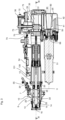
- the application device 1 has a cylinder-piston arrangement 10 ( Fig. 3 and 4 ) and is designed as a self-filling type in such a way that by a piston movement towards the dispensing area 6, the fluid is ejected and by an opposite movement of the piston, the cylinder is filled with the fluid for the next ejection process.
- the entire cylinder-piston assembly 10 is shown without the housing 2.
- the cylinder-piston assembly 10 comprises a front part 11 and a rear part 12 connected thereto.
- the front part 11 comprises a cylinder 13 for receiving the fluid, which has an open discharge end 14 in which a check valve 15 is seated, which is in fluid communication with a nozzle 16.
- the check valve 15 is also clearly visible in the illustration according to Fig. 34 and is designed to allow the fluid to be discharged from the cylinder 13 via the check valve 15 and the nozzle 16. Suction of air or liquid via the nozzle and the check valve 15 is not possible. In this direction, the check valve 15 closes.
- the front part 11 also has a connection 7 in which a further check valve 20 ( Fig. 3 ) that allows fluid communication from port 7 to cylinder 13 and blocks fluid communication in the opposite direction.
- Port 7 has a channel 21 that opens into cylinder 13 via several radial bores 22.
- the further check valve 20 can thus be referred to as an inlet valve and the check valve 15 can be referred to as an outlet valve.
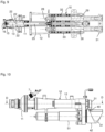
- a piston rod 25 is guided with a piston 26 formed at its end pointing towards the open discharge end 14, the piston 26 being shown in the sectional views of Fig. 3 and 4 is in its rear end position. In this position, cylinder 13 is filled with the fluid to be dispensed.
- the rear end 27 pointing away from the open discharge end 14 (well in Fig. 37 can be seen) of the piston rod 25 is connected via a plate 28 to a first guide rod 29 and a second guide rod 30, which extend parallel to each other and parallel to the piston rod 25 and which are guided in the rear part 12 ( Fig. 4 ).
- the ends of the guide rods 29 and 30 pointing away from the plate 28 are connected to a driver 31.
- a compression spring 32, 33 (e.g. coil spring) is arranged, the front ends of which each rest on the plate 28 and the rear ends of which each rest on a stop 34 of the rear part 12.
- the springs 32, 33 are tensioned.
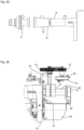
- a cover 35 and a metering adjustment device 36 are provided, which in the isometric view of the cylinder-piston arrangement 10 according to Fig. 6 are not shown, so that the driver 31 is clearly visible.
- the driver 31 has a rotatably mounted roller 40, wherein the axis of rotation of the roller 40 extends substantially perpendicular to the longitudinal axis of the piston rod 25.
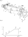
- the roller 40 runs on a ramp track 41 of a ramp 42 rotating beneath the roller 40, wherein the ramp track 41 has a single turn, as in particular Fig. 6 to 8 can be seen.
- This position of the piston 26 is shown, for example, in the sectional view according to Fig. 11 shown.
- the ramp track 41 has a lower plateau 43, followed by a gradient region 44 that extends to the upper plateau 45.
- the upper plateau 45 is followed by a transition region 46 that leads into a jump flank 47 (angle of rotation ⁇ 1), which leads back to the first plateau 43.
- angle of rotation range from ⁇ 0 to ⁇ 2 is equal to 360°.
- the jump flank 47 is characterized by its quasi-vertical nature, as it extends from height z1 to height z0 at a rotation angle (here ⁇ 2).
- the rotation angle range from ⁇ 1 to ⁇ 2 covers the transition region 46.
- the application device 1 is designed so that the fluid safely penetrates the skin and is applied into the underlying muscle.
- the piston 26 is then in its front end position, as shown in the sectional view in Fig. 11 is shown.
- the application device 1 is preferably designed such that, in the front end position of the piston 26, the driver 31 rests against the rear end of the rear part 12, whereby the rear end of the rear part 12 forms a stop for the driver 31. In this position, a desired minimum distance still exists between the roller 40 and the ramp track 41, so that the roller 40 does not reach the lower plateau 43 of the ramp track 41. This can prevent the roller 40 from hitting the ramp track 41 at the end of the ejection process, which could lead to damage to the roller 40.
- the plate 28, the springs 32, 33 including guide rods 29, 30, the driver 31 with roller 40, the ramp 42 together with the motor 51 and coupling 50 form a clamping device S for clamping the cylinder-piston arrangement 10.
- the application device 1 comprises a control unit 54 for controlling the motor 51 and all other electrical components of the device 1.
- a control unit 54 for controlling the motor 51 and all other electrical components of the device 1.
- Fig. 3 a circuit board with the control unit 54 is shown.
- the ramp is rotated further in the first rotational direction 52, so that the roller 40 runs from the upper plateau 45 over the transition area 46 and is then accelerated along the jump flank 47 to the lower plateau 53.
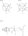
- the difficulty arises ( Fig. 12A - 12C ) that the spring force F of the tensioned springs 32, 33 has, in addition to a tangential component Ft, a component Fs perpendicular thereto, which includes a component Fd that points in the same direction as the force of the motor Fm for rotating the ramp 42.
- the roller 40 running over the transition area 46 accelerates the rotation of the ramp 42 (in addition to the rotation caused by the motor 51).
- This can disadvantageously result in the motor 51 acting as a generator for this additional acceleration and generating a voltage peak that can damage the control electronics of the control unit 54.
- the motor 51 acts as a brake, so that an undesirable braking effect occurs when the ramp 42 rotates, which changes the pressure curve during the application process in an undesirable manner.
- the coupling 50 is designed such that it transmits the torque provided by the motor 51 for rotating the ramp track 41 in the first direction of rotation 52 and at the same time has a freewheel opposite to the first direction of rotation 52, which is designed such that it covers at least the rotation angle range (from ⁇ 1 to ⁇ 2) corresponding to the transition range 46 (here, for example, 7°).
- a material that is as lightweight as possible is selected. Aluminum, magnesium, titanium, or plastic are preferred.
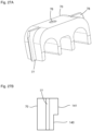
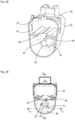
- the cover 35 comprises a first, second and third wiper 80, 81, 82 which, in the assembled state according to Fig. 3 , extend from a rear end of the cover 35 towards the discharge end of the application device 1.
- the scrapers 80-82 are formed on a frustoconical central part 83 and are spaced apart from each other in the circumferential direction.
- the frustoconical central part 83 tapers towards the discharge end, as in Fig. 3 is evident.
- the frustoconical central part 83 extends to the bottom 60 of the ramp 41.
- the first wiper 80 extends to the bottom 60.
- the first wiper 80 extends to the inside 84 of the wall 85, on the front side of which the ramp track 42 is formed ( Fig. 6 ).
- the second wiper 81 is shorter in both the axial and radial directions than the first wiper 80.
- the third wiper 82 is shorter in both the radial and axial directions than the second wiper 81.
- the cover 35 comprises an intermediate wall 86 in which an axially extending slot is formed, in which the roller 40, together with its mounting section of the driver 31, can move in the axial direction. Otherwise, the intermediate wall 86, together with the lower cover part 88, surrounds the outer side 89 of the wall 85 in the assembled state.
- a lubricant for example, a grease
- a grease is provided, which serves to ensure that the roller 40 rotates as smoothly as possible and is guided on the ramp track 41 with as little friction as possible.
- the wipers 80 to 82 move the grease that does not remain on the ramp track 41 back towards the ramp track and roller 40 due to the relative movement between the ramp track 41 and the wipers 80-82, so that permanent lubrication can be ensured.
- the lubricant that accumulates at the bottom of the cover 35 is conveyed back to the ramp track 41 and the roller 40, so that the desired permanent lubrication is ensured.
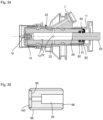
- FIG. 34 An enlarged sectional view of the front part 11 including the piston 26 and part of the piston rod 25 is shown.
- the cylinder 13 has an annular groove 90 in its rear area (facing away from the open discharge end 14), in which an O-ring 91 or a sealing ring 91 (e.g., an elastomer seal) is inserted for sealing.
- a first and a second support ring (92, 93) are arranged in the groove 90 such that the sealing ring 91 is positioned between the two support rings 92 and 93.
- the groove 90 and the support rings 92 and 93 are dimensioned such that the gap between the support rings 92 and 93 and the piston rod 25 is smaller than between the inside of the cylinder 13 and the piston rod 25.
- the support rings which can be made of PTFE or other plastics, ensure This prevents a part of the sealing ring 91 from being extruded into the gap between the piston rod 25 and the inside of the cylinder 13 due to the pressure or negative pressure built up when the piston rod 95 moves, which would destroy the sealing ring 91.
- the second support ring 93 prevents the described gap extrusion during movement of the piston rod 25 toward the open discharge end 14 and thus during application of the fluid.
- the first support ring 92 prevents the undesired gap extrusion during the opposite movement and thus during filling of the cylinder 13 with the fluid.
- the nozzle 16 has a tapered through-bore 95 through which the fluid is discharged during application.
- the necessary through-bore 95 can also be formed in an insert 96, as in Fig. 35 which is then to be screwed into the remaining nozzle body 97.
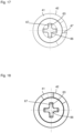
- the insert 96 comprises a base body 98 with an external thread, which comprises a receiving area 99 at the distal end.
- a sapphire element 100 is inserted into the receiving area 99, in which the last section of the through-bore 95 is formed.
- the diameter of the last section of the through-bore 95 is the smallest, or smaller, than the diameter of the sections of the through-bore 95 formed in the base body 98.
- the diameter of the last section of the through-bore 95 in the sapphire element 100 can, for example, be in the range of 0.30 to 0.38 mm, whereby the manufacturing tolerance should not be greater than 0.02 mm.
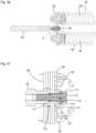
- piston rod 26 Since the unit consisting of piston rod 26, plate 28, and guide rods 29, 30 is relatively long and high forces are exerted during fluid application, it must be ensured that the piston rod 26 can move freely in the cylinder 13 and, for example, does not become jammed. To this end, the piston rod 26 should be aligned as parallel as possible to the guide rods 29, 30, and this should remain the case even over long periods of use of the application device 1.
- the piston rod 25 is not absolutely rigidly connected to the plate 28.
- the connection is designed to allow tilting or rotation of the piston rod 26 relative to the plate 28.
- the piston rod 25 is thus connected to the plate 28 via a swivel joint.
- a first washer 110 is provided between the rear end 27 of the piston rod 25 and the plate 28.
- a fixing screw 111 is inserted into the rear end 27, which is inserted through a corresponding hole in the Plate 28 runs, screwed in. Between a head 112 of the fixing screw 111, a second and a third washer 113, 114 are arranged.
- the rear end 27 is rounded (here, for example, spherical) and the side of the first washer 110 facing the rear end 27 is correspondingly concave, so that this side forms a bed for the rear end 27.
- the first washer 110 sits in a recess in the plate 28, so that the first washer 110 cannot move transversely to the longitudinal direction of the piston rod 25.
- the side of the first washer 110 facing away from the rear end 27 is flat, since the corresponding bottom of the recess in the plate 28 is also flat.
- the first washer can also be described as concave-flat.
- the second and third washers 113 and 114 are designed such that the sides facing each other are again curved.
- the side of the second washer 113 facing the third washer 114 has a convex curvature.
- the side of the third washer 114 facing the second washer 113 is correspondingly concavely curved.
- the other sides of the second and third washers 113, 114 are flat.
- the head 112 of the fixing screw 111 presses the third washer 114 onto the second washer 113, which is thereby pressed against the side of the plate 28 facing away from the rear end 27.
- the second washer 113 is thus plano-convex
- the third washer 114 is thus concave-flat.
- the pivot point 115 for the rotation of the piston rod 25 relative to the plate 28 is spaced from the plate 28 and on the side of the screw head 112.
- the motor 51 can be designed as an electric motor, and in particular as a brushless electric motor. This improves the durability of the application device 1, since electric motors with brushes can be problematic because the brushes can break due to the vibrations that occur during fluid application.
- a sensor 55 is provided, which in the embodiment described here is located in front of the further check valve 20 (which can also be referred to as an inlet valve).
- the sensor 55 can, for example, distinguish air from liquid, so that It can be avoided that the application device 1 carries out an application process when there is no liquid in the cylinder 13. This can prevent damage to the application device 1, since it is designed such that the liquid dampens the movement of the piston rod 25 or the piston 26 during application towards the open dispensing end.
- the sensor 55 can be designed as a voltage sensor, as a capacitive sensor or, for example, as a light barrier.
- the housing 2 may have a luminous area 120 ( Fig. 1 ), which can illuminate in different colors.
- the area 120 can, for example, be striped or have any other shape.
- the different colors can be used to communicate user information about the status of the application device 1. For example, a first color (for example, the color red) can be used to inform the user that the device 1 is not ready to be used. A second color can be used to inform that it is basically ready for operation. A third color can be used to inform that the cylinder-piston arrangement 10 is tensioned and that an application process can be carried out by actuating the trigger 5. A fourth color (for example, green) can be used to inform the user that the application process was successful. Furthermore, another color can be used to inform the user that an error condition exists.
- a first color for example, the color red
- a second color can be used to inform that it is basically ready for operation.
- a third color can be used to inform that the cylinder-piston arrangement 10 is tensioned and that an application process can be carried out
- the described information can be communicated not only using different colors, but also using the same colors, if the differences are represented, for example, by different flashing. It is also possible to provide the user with haptic or acoustic feedback instead of the described optical feedback. Of course, the visual, haptic and acoustic feedback can also be combined.
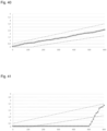
- the application device 1 can have an acceleration sensor 130, which, for example, is only Fig. 3 Since the measured acceleration values for a correct application process differ from those of an incorrect application process, the measured values can be used to decide whether an application process was successful or not.
- Fig. 39 An example of an unsuccessful application process (hereinafter referred to as a shot) is shown.
- the acceleration values exceed the maximum value of the test curve, so it can be assumed that the shot was unsuccessful.
- the current consumption of the motor 51 can be measured and evaluated to assess the quality of the shot.
- a sensor 131 for measuring sound or tones can be provided, which is shown schematically in Fig. 3 is shown.
- the application process is assessed as unsuccessful.
- the temporal progression of the measured pitch can also, for example, fall below a temporal progression of a lower limit, which suggests a faulty application process.
- a measured frequency spectrum can also be evaluated as a parameter that must fulfill a target temporal progression in order for the application process to be assessed as successful.
- the temporal progression of the intensity (or volume) can be used as a parameter, which in turn must fulfill a target temporal progression.
- the control unit 54 can perform the described measurement and evaluation of the parameters to determine whether the application process was successful or not. Depending on the decision, the control unit can, for example, generate optical, haptic, and/or acoustic feedback in the manner described.
Landscapes
- Health & Medical Sciences (AREA)
- Life Sciences & Earth Sciences (AREA)
- Veterinary Medicine (AREA)
- Engineering & Computer Science (AREA)
- Public Health (AREA)
- General Health & Medical Sciences (AREA)
- Animal Behavior & Ethology (AREA)
- Biomedical Technology (AREA)
- Hematology (AREA)
- Heart & Thoracic Surgery (AREA)
- Anesthesiology (AREA)
- Vascular Medicine (AREA)
- Wood Science & Technology (AREA)
- Zoology (AREA)
- Surgery (AREA)
- Infusion, Injection, And Reservoir Apparatuses (AREA)
- Emergency Medicine (AREA)
- Actuator (AREA)
Claims (7)
- Dispositif pour appliquer un fluide, comprenantun cylindre (13) qui possède une extrémité de sortie ouverte (14),un piston (26) pouvant coulisser dans le cylindre (13) entre une position avant et une position arrière et relié à une tige de piston (25) qui dépasse dans une première direction au-delà d'une extrémité arrière du cylindre (13) opposée à l'extrémité de sortie ouverte (14),un clapet anti-retour (15) fermant l'extrémité de sortie ouverte etun dispositif de serrage (S) relié à la tige de piston (25);le dispositif de serrage (S) pouvant déplacer la tige de piston (25) dans une opération de serrage le long de la première direction jusqu'à ce que le piston (26) se trouve dans sa position arrière finale, afin de remplir ainsi le cylindre (13) avec le fluide à appliquer et de précontraindre la tige de piston (25) vers l'extrémité de sortie ouverte (14), etle dispositif de serrage (S), lorsque le piston (26) se trouve dans sa position arrière extrême, peut libérer la tige de piston (25) lors d'une opération de distribution, de sorte que le piston (26), en raison de la précontrainte appliquée, se déplace dans le sens opposé à la première direction vers l'extrémité de distribution ouverte (14) et que le fluide dans le cylindre (13) est distribué via le clapet anti-retour (15) pour être appliqué,le dispositif de serrage (S) possède une rampe (42) pouvant être tournée au moyen d'un moteur (51) avec une trajectoire de rampe (41) s'étendant le long d'une ligne hélicoïdale,la rampe (41) montant depuis un premier plateau (43) le long d'une zone inclinée (44) jusqu'à un deuxième plateau (45) et descendant depuis le deuxième plateau (45) vers le premier plateau (43) via un flanc de saut (47), la rampe (41) comportant une zone de transition (46) reliant le deuxième plateau (45) et le flanc de saut (47),le dispositif de serrage (S) comportant en outre un rouleau (40) en contact avec la rampe (41), qui est monté de manière rotative dans un entraîneur (31) relié à la tige de piston (25) de telle sorte que, lors de la rotation de la rampe (42) dans un premier sens de rotation (52), la rampe (41) passe sous le rouleau (40) qui tourne alors,la rampe (41) étant tournée dans le premier sens de rotation (52) pour l'opération de serrage, de telle sorte que le rouleau (40) se déplace sur la zone inclinée (44) jusqu'au deuxième plateau (45) et que le piston (26) soit ainsi amené dans sa position arrière finale,la rampe (41) étant tournée, pour l'opération de distribution, à partir d'un contact du rouleau (40) avec le deuxième plateau (45) le long du premier sens de rotation (52) jusqu'à ce que le rouleau (40) passe sur la zone de transition (46) et, en raison de la précontrainte, accélère vers le premier plateau (43) et déplace ainsi le piston (26) vers l'extrémité de distribution ouverte (14), le dispositif (1) pour l'application possédant exactement un cylindre (13) avec exactement un piston (26) et exactement une tige de piston (25),caractérisé en ce quele dispositif de serrage (S) possède deux ressorts hélicoïdaux (32, 33) parallèles entre eux, qui sont disposés à distance l'un de l'autre transversalement à leurs directions longitudinales et qui contribuent tous deux à la précontrainte appliquée lorsque le piston (26) se trouve dans sa position d'extrémité arrière.
- Dispositif selon la revendication 1,
les deux ressorts hélicoïdaux possèdent les mêmes dimensions. - Dispositif selon l'une des revendications précédentes, dans lequel
les ressorts hélicoïdaux (32, 33) sont disposés de telle sorte que leurs directions longitudinales sont parallèles à la direction longitudinale de la tige de piston (25). - Dispositif selon l'une des revendications précédentes, dans lequel
les ressorts hélicoïdaux (32, 33) sont conçus comme des ressorts de pression. - Dispositif selon l'une des revendications précédentes, dans lequella tige de piston (25) est reliée à deux tiges de guidage (29, 30) par l'intermédiaire d'une pièce de liaison (28), etles tiges de guidage (29, 30) s'étendent à l'intérieur des ressorts hélicoïdaux (32, 33).
- Dispositif selon l'une des revendications précédentes, dans lequel
le dispositif de serrage possède au moins trois ressorts hélicoïdaux parallèles entre eux. - Dispositif selon la revendication 6, dans lequel
les ressorts hélicoïdaux sont disposés dans un plan perpendiculaire à la direction longitudinale des ressorts hélicoïdaux et symétriquement par rapport au moteur (51).
Applications Claiming Priority (2)
| Application Number | Priority Date | Filing Date | Title |
|---|---|---|---|
| DE102019123732.7A DE102019123732A1 (de) | 2019-09-04 | 2019-09-04 | Vorrichtung zum Applizieren eines Fluids |
| PCT/EP2020/069454 WO2021043475A1 (fr) | 2019-09-04 | 2020-07-09 | Dispositif d'administration d'un fluide |
Publications (3)
| Publication Number | Publication Date |
|---|---|
| EP4003468A1 EP4003468A1 (fr) | 2022-06-01 |
| EP4003468C0 EP4003468C0 (fr) | 2025-07-09 |
| EP4003468B1 true EP4003468B1 (fr) | 2025-07-09 |
Family
ID=71614876
Family Applications (1)
| Application Number | Title | Priority Date | Filing Date |
|---|---|---|---|
| EP20740277.7A Active EP4003468B1 (fr) | 2019-09-04 | 2020-07-09 | Dispostif pour appliquer un fluide |
Country Status (8)
| Country | Link |
|---|---|
| US (1) | US20220313917A1 (fr) |
| EP (1) | EP4003468B1 (fr) |
| KR (1) | KR102918260B1 (fr) |
| CN (1) | CN114340553B (fr) |
| AU (1) | AU2020342246B2 (fr) |
| DE (1) | DE102019123732A1 (fr) |
| ES (1) | ES3040073T3 (fr) |
| WO (1) | WO2021043475A1 (fr) |
Family Cites Families (15)
| Publication number | Priority date | Publication date | Assignee | Title |
|---|---|---|---|---|
| US2928390A (en) * | 1957-07-15 | 1960-03-15 | Scherer Corp R P | Multi-dose hypodermic injector |
| US3057349A (en) * | 1959-12-14 | 1962-10-09 | Ismach Aaron | Multi-dose jet injection device |
| GB993309A (en) * | 1961-04-11 | 1965-05-26 | Express Injector Company Ltd | Improved hypodermic injector |
| US4416279A (en) * | 1981-06-19 | 1983-11-22 | Lindner James A | Capillary blood sampling device |
| GB9118204D0 (en) * | 1991-08-23 | 1991-10-09 | Weston Terence E | Needle-less injector |
| DE10232412A1 (de) | 2002-07-17 | 2004-02-05 | Disetronic Licensing Ag | Verabreichungsgerät mit Primingfunktion |
| EP1773424B1 (fr) | 2004-06-09 | 2012-08-01 | Mark Anderson and Associates, Incorporated | Systeme d'injection hypodermique |
| AU2007257173B2 (en) | 2006-06-07 | 2013-03-14 | Acushot Inc. | Charging mechanism for a needle-free injector |
| GB2545266B (en) * | 2015-12-11 | 2018-08-08 | Oval Medical Tech Limited | Autoinjector with retracting needle |
| CN205359706U (zh) * | 2016-01-11 | 2016-07-06 | 信阳农林学院 | 一种兽用注射器 |
| US20200023128A1 (en) * | 2016-12-22 | 2020-01-23 | Intervet Inc. | Needleless injector |
| DE102018107103A1 (de) * | 2018-03-26 | 2019-09-26 | Henke-Sass, Wolf Gmbh | Vorrichtung zum Applizieren eines Fluids |
| DE102018107102A1 (de) * | 2018-03-26 | 2019-09-26 | Henke-Sass, Wolf Gmbh | Vorrichtung zum Applizieren eines Fluids |
| DE102018107100A1 (de) * | 2018-03-26 | 2019-09-26 | Henke-Sass, Wolf Gmbh | Vorrichtung zum Applizieren eines Fluids |
| DE102018107101A1 (de) * | 2018-03-26 | 2019-09-26 | Henke-Sass, Wolf Gmbh | Vorrichtung zum Applizieren eines Fluids |
-
2019
- 2019-09-04 DE DE102019123732.7A patent/DE102019123732A1/de active Pending
-
2020
- 2020-07-09 AU AU2020342246A patent/AU2020342246B2/en active Active
- 2020-07-09 WO PCT/EP2020/069454 patent/WO2021043475A1/fr not_active Ceased
- 2020-07-09 ES ES20740277T patent/ES3040073T3/es active Active
- 2020-07-09 US US17/640,239 patent/US20220313917A1/en active Pending
- 2020-07-09 EP EP20740277.7A patent/EP4003468B1/fr active Active
- 2020-07-09 KR KR1020227008138A patent/KR102918260B1/ko active Active
- 2020-07-09 CN CN202080061232.1A patent/CN114340553B/zh active Active
Also Published As
| Publication number | Publication date |
|---|---|
| KR20220058913A (ko) | 2022-05-10 |
| EP4003468C0 (fr) | 2025-07-09 |
| AU2020342246B2 (en) | 2025-08-14 |
| NZ785625A (en) | 2024-05-31 |
| KR102918260B1 (ko) | 2026-01-27 |
| CN114340553B (zh) | 2024-12-27 |
| AU2020342246A1 (en) | 2022-04-07 |
| EP4003468A1 (fr) | 2022-06-01 |
| US20220313917A1 (en) | 2022-10-06 |
| DE102019123732A1 (de) | 2021-03-04 |
| WO2021043475A1 (fr) | 2021-03-11 |
| ES3040073T3 (en) | 2025-10-28 |
| CN114340553A (zh) | 2022-04-12 |
Similar Documents
| Publication | Publication Date | Title |
|---|---|---|
| EP3773803B1 (fr) | Dispositif d'application d'un fluide | |
| EP3773804B1 (fr) | Dispositif d'application d'un fluide | |
| EP3773802B1 (fr) | Dispositif d'application d'un fluide | |
| EP3773814A1 (fr) | Dispositif d'application d'un fluide | |
| EP0245312A1 (fr) | Instrument d'injection. | |
| EP4003462B1 (fr) | Dispositif pour administrer un fluide | |
| DE3443167A1 (de) | Chirurgische zement-spritze | |
| WO2021043476A1 (fr) | Dispositif d'administration de flude | |
| EP4003463B1 (fr) | Dispositif d'application de fluide | |
| EP4003464B1 (fr) | Dispositif d'administration d'un fluide | |
| EP4003468B1 (fr) | Dispostif pour appliquer un fluide | |
| EP4003461B1 (fr) | Dispositif d'application de fluide | |
| EP4003460B1 (fr) | Dispositif d'application de fluide | |
| EP4106846B1 (fr) | Dispositif d'administration d'un fluide | |
| DE3800355C2 (de) | Kompressor | |
| EP1538336B1 (fr) | Pompe de dosage | |
| DE20016079U1 (de) | Gerät und Adapter für kanülenlose medizinische Spritzen |
Legal Events
| Date | Code | Title | Description |
|---|---|---|---|
| STAA | Information on the status of an ep patent application or granted ep patent |
Free format text: STATUS: UNKNOWN |
|
| STAA | Information on the status of an ep patent application or granted ep patent |
Free format text: STATUS: THE INTERNATIONAL PUBLICATION HAS BEEN MADE |
|
| PUAI | Public reference made under article 153(3) epc to a published international application that has entered the european phase |
Free format text: ORIGINAL CODE: 0009012 |
|
| STAA | Information on the status of an ep patent application or granted ep patent |
Free format text: STATUS: REQUEST FOR EXAMINATION WAS MADE |
|
| 17P | Request for examination filed |
Effective date: 20220223 |
|
| AK | Designated contracting states |
Kind code of ref document: A1 Designated state(s): AL AT BE BG CH CY CZ DE DK EE ES FI FR GB GR HR HU IE IS IT LI LT LU LV MC MK MT NL NO PL PT RO RS SE SI SK SM TR |
|
| DAV | Request for validation of the european patent (deleted) | ||
| DAX | Request for extension of the european patent (deleted) | ||
| GRAP | Despatch of communication of intention to grant a patent |
Free format text: ORIGINAL CODE: EPIDOSNIGR1 |
|
| STAA | Information on the status of an ep patent application or granted ep patent |
Free format text: STATUS: GRANT OF PATENT IS INTENDED |
|
| INTG | Intention to grant announced |
Effective date: 20250224 |
|
| GRAS | Grant fee paid |
Free format text: ORIGINAL CODE: EPIDOSNIGR3 |
|
| GRAA | (expected) grant |
Free format text: ORIGINAL CODE: 0009210 |
|
| STAA | Information on the status of an ep patent application or granted ep patent |
Free format text: STATUS: THE PATENT HAS BEEN GRANTED |
|
| AK | Designated contracting states |
Kind code of ref document: B1 Designated state(s): AL AT BE BG CH CY CZ DE DK EE ES FI FR GB GR HR HU IE IS IT LI LT LU LV MC MK MT NL NO PL PT RO RS SE SI SK SM TR |
|
| REG | Reference to a national code |
Ref country code: GB Ref legal event code: FG4D Free format text: NOT ENGLISH |
|
| REG | Reference to a national code |
Ref country code: CH Ref legal event code: EP |
|
| REG | Reference to a national code |
Ref country code: IE Ref legal event code: FG4D Free format text: LANGUAGE OF EP DOCUMENT: GERMAN |
|
| REG | Reference to a national code |
Ref country code: DE Ref legal event code: R096 Ref document number: 502020011396 Country of ref document: DE |
|
| U01 | Request for unitary effect filed |
Effective date: 20250710 |
|
| U07 | Unitary effect registered |
Designated state(s): AT BE BG DE DK EE FI FR IT LT LU LV MT NL PT RO SE SI Effective date: 20250717 |
|
| PGFP | Annual fee paid to national office [announced via postgrant information from national office to epo] |
Ref country code: ES Payment date: 20250827 Year of fee payment: 6 |
|
| PGFP | Annual fee paid to national office [announced via postgrant information from national office to epo] |
Ref country code: GB Payment date: 20250820 Year of fee payment: 6 |
|
| PGFP | Annual fee paid to national office [announced via postgrant information from national office to epo] |
Ref country code: CH Payment date: 20250801 Year of fee payment: 6 |
|
| REG | Reference to a national code |
Ref country code: ES Ref legal event code: FG2A Ref document number: 3040073 Country of ref document: ES Kind code of ref document: T3 Effective date: 20251028 |
|
| U20 | Renewal fee for the european patent with unitary effect paid |
Year of fee payment: 6 Effective date: 20250924 |
|
| PG25 | Lapsed in a contracting state [announced via postgrant information from national office to epo] |
Ref country code: IS Free format text: LAPSE BECAUSE OF FAILURE TO SUBMIT A TRANSLATION OF THE DESCRIPTION OR TO PAY THE FEE WITHIN THE PRESCRIBED TIME-LIMIT Effective date: 20251109 |
|
| PG25 | Lapsed in a contracting state [announced via postgrant information from national office to epo] |
Ref country code: NO Free format text: LAPSE BECAUSE OF FAILURE TO SUBMIT A TRANSLATION OF THE DESCRIPTION OR TO PAY THE FEE WITHIN THE PRESCRIBED TIME-LIMIT Effective date: 20251009 |
|
| PG25 | Lapsed in a contracting state [announced via postgrant information from national office to epo] |
Ref country code: HR Free format text: LAPSE BECAUSE OF FAILURE TO SUBMIT A TRANSLATION OF THE DESCRIPTION OR TO PAY THE FEE WITHIN THE PRESCRIBED TIME-LIMIT Effective date: 20250709 |
|
| PG25 | Lapsed in a contracting state [announced via postgrant information from national office to epo] |
Ref country code: GR Free format text: LAPSE BECAUSE OF FAILURE TO SUBMIT A TRANSLATION OF THE DESCRIPTION OR TO PAY THE FEE WITHIN THE PRESCRIBED TIME-LIMIT Effective date: 20251010 |
|
| PG25 | Lapsed in a contracting state [announced via postgrant information from national office to epo] |
Ref country code: PL Free format text: LAPSE BECAUSE OF FAILURE TO SUBMIT A TRANSLATION OF THE DESCRIPTION OR TO PAY THE FEE WITHIN THE PRESCRIBED TIME-LIMIT Effective date: 20250709 |
|
| PG25 | Lapsed in a contracting state [announced via postgrant information from national office to epo] |
Ref country code: RS Free format text: LAPSE BECAUSE OF FAILURE TO SUBMIT A TRANSLATION OF THE DESCRIPTION OR TO PAY THE FEE WITHIN THE PRESCRIBED TIME-LIMIT Effective date: 20251009 |
|
| PG25 | Lapsed in a contracting state [announced via postgrant information from national office to epo] |
Ref country code: SM Free format text: LAPSE BECAUSE OF FAILURE TO SUBMIT A TRANSLATION OF THE DESCRIPTION OR TO PAY THE FEE WITHIN THE PRESCRIBED TIME-LIMIT Effective date: 20250709 |
|
| PG25 | Lapsed in a contracting state [announced via postgrant information from national office to epo] |
Ref country code: CZ Free format text: LAPSE BECAUSE OF FAILURE TO SUBMIT A TRANSLATION OF THE DESCRIPTION OR TO PAY THE FEE WITHIN THE PRESCRIBED TIME-LIMIT Effective date: 20250709 |
|
| PG25 | Lapsed in a contracting state [announced via postgrant information from national office to epo] |
Ref country code: SK Free format text: LAPSE BECAUSE OF FAILURE TO SUBMIT A TRANSLATION OF THE DESCRIPTION OR TO PAY THE FEE WITHIN THE PRESCRIBED TIME-LIMIT Effective date: 20250709 |