EP3783178A2 - Porte - Google Patents
Porte Download PDFInfo
- Publication number
- EP3783178A2 EP3783178A2 EP20213516.6A EP20213516A EP3783178A2 EP 3783178 A2 EP3783178 A2 EP 3783178A2 EP 20213516 A EP20213516 A EP 20213516A EP 3783178 A2 EP3783178 A2 EP 3783178A2
- Authority
- EP
- European Patent Office
- Prior art keywords
- door
- profile
- cover profile
- fastening
- hinge
- Prior art date
- Legal status (The legal status is an assumption and is not a legal conclusion. Google has not performed a legal analysis and makes no representation as to the accuracy of the status listed.)
- Granted
Links
Images
Classifications
-
- E—FIXED CONSTRUCTIONS
- E05—LOCKS; KEYS; WINDOW OR DOOR FITTINGS; SAFES
- E05D—HINGES OR SUSPENSION DEVICES FOR DOORS, WINDOWS OR WINGS
- E05D5/00—Construction of single parts, e.g. the parts for attachment
- E05D5/02—Parts for attachment, e.g. flaps
- E05D5/04—Flat flaps
-
- E—FIXED CONSTRUCTIONS
- E05—LOCKS; KEYS; WINDOW OR DOOR FITTINGS; SAFES
- E05D—HINGES OR SUSPENSION DEVICES FOR DOORS, WINDOWS OR WINGS
- E05D11/00—Additional features or accessories of hinges
-
- E—FIXED CONSTRUCTIONS
- E05—LOCKS; KEYS; WINDOW OR DOOR FITTINGS; SAFES
- E05D—HINGES OR SUSPENSION DEVICES FOR DOORS, WINDOWS OR WINGS
- E05D11/00—Additional features or accessories of hinges
- E05D11/0054—Covers, e.g. for protection
-
- E—FIXED CONSTRUCTIONS
- E06—DOORS, WINDOWS, SHUTTERS, OR ROLLER BLINDS IN GENERAL; LADDERS
- E06B—FIXED OR MOVABLE CLOSURES FOR OPENINGS IN BUILDINGS, VEHICLES, FENCES OR LIKE ENCLOSURES IN GENERAL, e.g. DOORS, WINDOWS, BLINDS, GATES
- E06B7/00—Special arrangements or measures in connection with doors or windows
- E06B7/28—Other arrangements on doors or windows, e.g. door-plates, windows adapted to carry plants, hooks for window cleaners
- E06B7/36—Finger guards or other measures preventing harmful access between the door and the door frame
- E06B7/367—Finger guards or other measures preventing harmful access between the door and the door frame by covering the gap between the door and the door frame at the hinge side
-
- E—FIXED CONSTRUCTIONS
- E05—LOCKS; KEYS; WINDOW OR DOOR FITTINGS; SAFES
- E05D—HINGES OR SUSPENSION DEVICES FOR DOORS, WINDOWS OR WINGS
- E05D11/00—Additional features or accessories of hinges
- E05D11/0054—Covers, e.g. for protection
- E05D2011/0072—Covers, e.g. for protection for the gap between hinge parts
-
- E—FIXED CONSTRUCTIONS
- E05—LOCKS; KEYS; WINDOW OR DOOR FITTINGS; SAFES
- E05Y—INDEXING SCHEME ASSOCIATED WITH SUBCLASSES E05D AND E05F, RELATING TO CONSTRUCTION ELEMENTS, ELECTRIC CONTROL, POWER SUPPLY, POWER SIGNAL OR TRANSMISSION, USER INTERFACES, MOUNTING OR COUPLING, DETAILS, ACCESSORIES, AUXILIARY OPERATIONS NOT OTHERWISE PROVIDED FOR, APPLICATION THEREOF
- E05Y2600/00—Mounting or coupling arrangements for elements provided for in this subclass
- E05Y2600/10—Adjustable
- E05Y2600/12—Adjustable by manual operation
-
- E—FIXED CONSTRUCTIONS
- E05—LOCKS; KEYS; WINDOW OR DOOR FITTINGS; SAFES
- E05Y—INDEXING SCHEME ASSOCIATED WITH SUBCLASSES E05D AND E05F, RELATING TO CONSTRUCTION ELEMENTS, ELECTRIC CONTROL, POWER SUPPLY, POWER SIGNAL OR TRANSMISSION, USER INTERFACES, MOUNTING OR COUPLING, DETAILS, ACCESSORIES, AUXILIARY OPERATIONS NOT OTHERWISE PROVIDED FOR, APPLICATION THEREOF
- E05Y2600/00—Mounting or coupling arrangements for elements provided for in this subclass
- E05Y2600/50—Mounting methods; Positioning
- E05Y2600/502—Clamping
-
- E—FIXED CONSTRUCTIONS
- E05—LOCKS; KEYS; WINDOW OR DOOR FITTINGS; SAFES
- E05Y—INDEXING SCHEME ASSOCIATED WITH SUBCLASSES E05D AND E05F, RELATING TO CONSTRUCTION ELEMENTS, ELECTRIC CONTROL, POWER SUPPLY, POWER SIGNAL OR TRANSMISSION, USER INTERFACES, MOUNTING OR COUPLING, DETAILS, ACCESSORIES, AUXILIARY OPERATIONS NOT OTHERWISE PROVIDED FOR, APPLICATION THEREOF
- E05Y2800/00—Details, accessories and auxiliary operations not otherwise provided for
- E05Y2800/15—Applicability
- E05Y2800/17—Universally applicable
-
- E—FIXED CONSTRUCTIONS
- E05—LOCKS; KEYS; WINDOW OR DOOR FITTINGS; SAFES
- E05Y—INDEXING SCHEME ASSOCIATED WITH SUBCLASSES E05D AND E05F, RELATING TO CONSTRUCTION ELEMENTS, ELECTRIC CONTROL, POWER SUPPLY, POWER SIGNAL OR TRANSMISSION, USER INTERFACES, MOUNTING OR COUPLING, DETAILS, ACCESSORIES, AUXILIARY OPERATIONS NOT OTHERWISE PROVIDED FOR, APPLICATION THEREOF
- E05Y2800/00—Details, accessories and auxiliary operations not otherwise provided for
- E05Y2800/26—Form or shape
- E05Y2800/262—Form or shape column shaped
-
- E—FIXED CONSTRUCTIONS
- E05—LOCKS; KEYS; WINDOW OR DOOR FITTINGS; SAFES
- E05Y—INDEXING SCHEME ASSOCIATED WITH SUBCLASSES E05D AND E05F, RELATING TO CONSTRUCTION ELEMENTS, ELECTRIC CONTROL, POWER SUPPLY, POWER SIGNAL OR TRANSMISSION, USER INTERFACES, MOUNTING OR COUPLING, DETAILS, ACCESSORIES, AUXILIARY OPERATIONS NOT OTHERWISE PROVIDED FOR, APPLICATION THEREOF
- E05Y2800/00—Details, accessories and auxiliary operations not otherwise provided for
- E05Y2800/26—Form or shape
- E05Y2800/266—Form or shape curved
-
- E—FIXED CONSTRUCTIONS
- E05—LOCKS; KEYS; WINDOW OR DOOR FITTINGS; SAFES
- E05Y—INDEXING SCHEME ASSOCIATED WITH SUBCLASSES E05D AND E05F, RELATING TO CONSTRUCTION ELEMENTS, ELECTRIC CONTROL, POWER SUPPLY, POWER SIGNAL OR TRANSMISSION, USER INTERFACES, MOUNTING OR COUPLING, DETAILS, ACCESSORIES, AUXILIARY OPERATIONS NOT OTHERWISE PROVIDED FOR, APPLICATION THEREOF
- E05Y2800/00—Details, accessories and auxiliary operations not otherwise provided for
- E05Y2800/40—Physical or chemical protection
- E05Y2800/41—Physical or chemical protection against finger injury
-
- E—FIXED CONSTRUCTIONS
- E05—LOCKS; KEYS; WINDOW OR DOOR FITTINGS; SAFES
- E05Y—INDEXING SCHEME ASSOCIATED WITH SUBCLASSES E05D AND E05F, RELATING TO CONSTRUCTION ELEMENTS, ELECTRIC CONTROL, POWER SUPPLY, POWER SIGNAL OR TRANSMISSION, USER INTERFACES, MOUNTING OR COUPLING, DETAILS, ACCESSORIES, AUXILIARY OPERATIONS NOT OTHERWISE PROVIDED FOR, APPLICATION THEREOF
- E05Y2800/00—Details, accessories and auxiliary operations not otherwise provided for
- E05Y2800/67—Materials; Strength alteration thereof
- E05Y2800/684—Strength alteration by weakening, e.g. by applying grooves
-
- E—FIXED CONSTRUCTIONS
- E05—LOCKS; KEYS; WINDOW OR DOOR FITTINGS; SAFES
- E05Y—INDEXING SCHEME ASSOCIATED WITH SUBCLASSES E05D AND E05F, RELATING TO CONSTRUCTION ELEMENTS, ELECTRIC CONTROL, POWER SUPPLY, POWER SIGNAL OR TRANSMISSION, USER INTERFACES, MOUNTING OR COUPLING, DETAILS, ACCESSORIES, AUXILIARY OPERATIONS NOT OTHERWISE PROVIDED FOR, APPLICATION THEREOF
- E05Y2900/00—Application of doors, windows, wings or fittings thereof
- E05Y2900/10—Application of doors, windows, wings or fittings thereof for buildings or parts thereof
- E05Y2900/13—Type of wing
- E05Y2900/132—Doors
Definitions
- the present invention relates to a door according to the preamble of claim 1.
- Doors with a door leaf, a door hinge and a door frame are known from the prior art.
- the door leaf is pivotably connected to the door frame via the door hinge.
- This side is also known as the hinge side. It is therefore a gap on the hinge side.
- the size of the gap on the hinge side changes during the pivoting movement of the door leaf, so there is a risk of a human finder being crushed. This is especially true for children's fingers, as these are smaller and children particularly often stick their fingers in this gap.
- DE 20 2014 101 362 U1 discloses a device with which such a gap on the belt side can be at least partially covered in order to reduce the risk of fingers being crushed.
- the present invention is based on the object of creating a more flexible way of increasing security on the hinge side of the door.
- the door comprises a door leaf, a door hinge, a door frame, a fastening profile and a cover profile.
- the door leaf has two Main surfaces and two minor surfaces. The area of the main surfaces is in each case many times greater than the area of the secondary surfaces. For example, the main surfaces can be the surfaces that are visible when the door is closed.
- the door hinge is attached to a lateral end area of the door leaf. In the context of this description, the lateral end area is understood to mean, in particular, the hinge side of the door leaf.
- the door leaf is pivotably connected to the door frame via the door hinge.
- the fastening profile is attached to the door leaf or to the door frame.
- the cover profile is connected to the fastening profile.
- the cover profile at least partially covers a gap between the door leaf and the door frame, which gap is arranged adjacent to the lateral end region. It is therefore the gap on the hinge side.
- the cover profile has a hinge section which is arranged exclusively above and below the door hinge. This can mean in particular that the hinge section is not arranged laterally offset from the door hinge. It is also possible, for example, for the entire section of the cover profile which is arranged above and below the door hinge to represent the hinge section.
- the hinge section can also be arranged between the two of the door hinges. In the context of this description, this possibility is explicitly understood as being above a first of the door hinges and below a second of the door hinges.
- the band section is arranged offset to the fastening profile in a horizontal direction parallel to the main surfaces.
- a geometric plane is understood to mean, in particular, a virtual plane that is not present as a component.
- the band section can also be arranged offset to the fastening profile in a horizontal direction perpendicular to the main surfaces.
- the arrangement of the band section is advantageous because a flatter design of the combination of fastening profile and cover profile can be achieved.
- this combination can also be used with doors in which the door hinge has a relatively small distance in a horizontal direction perpendicular to the main surface of the door leaf.
- a distance between the cover profile and the main surfaces can be adjustable.
- the distance can be adjustable in a horizontal direction perpendicular to the main surfaces. This allows the position of the cover profile, in particular of the hinge section, to be adapted to the position of the door hinge.
- the cover profile can be connected to the fastening profile via a connecting element.
- a connecting element is particularly advantageous for a simple structure of the Cover profile.
- the cover profile can thus have a geometry that is relatively easy to manufacture. It only needs to be connectable to the connecting element.
- the connecting element can have two legs, between which the cover profile is fastened, in particular clamped or screwed.
- the legs can extend laterally away from the fastening profile in their transverse direction.
- a transverse direction is understood to mean, in particular, the direction that runs horizontally parallel to the main surfaces.
- the door can comprise a cover profile.
- the cover profile can be fastened, in particular directly, to the fastening profile and define an interior space together with the fastening profile.
- the cover profile can protect the interior from dirt and damage, for example.
- the cover profile can also be fastened to another component, for example a base element or a fastening element, which is fastened to the door leaf or the door frame.
- the cover profile in particular the band section, can protrude from the interior.
- the cover profile, in particular the strip section can protrude from the interior space in a horizontal direction parallel to the main surfaces.
- a distance adjustment mechanism can be arranged within the interior space.
- the distance of the cover profile in the horizontal direction perpendicular to the main surfaces from the door leaf can be adjustable by means of the distance adjustment mechanism.
- the band portion may be arranged offset in a horizontal direction parallel to the main surfaces with respect to the spacing adjustment mechanism. It is particularly possible here for the connecting element to be adjusted. In this case, the cover profile is moved with it because it is attached to the connecting element.
- the cover profile can overlap with the cover profile in a horizontal direction perpendicular to the main surfaces. This can mean that there is a geometric plane which is arranged perpendicular to the main surfaces and which intersects both the cover profile and the cover profile.
- the cover profile can thus comprise the band section, which is spaced apart from the fastening profile in a horizontal direction parallel to the main surfaces, and a connecting section that is not spaced apart in the horizontal direction parallel to the main surfaces of the fastening profile.
- the door can have a first end cap and a second end cap.
- the first end cap can be fastened to a first end of the fastening profile and / or to a first end of the cover profile.
- the second end cap can be at a second end of the fastening profile and / or be attached to a second end of the cover profile.
- the first end can be arranged opposite the second end.
- the end caps can, for example, close the interior at the top and bottom.
- the cover profile, the fastening profile and the end caps can be connected to one another in such a way that no screw connections are visible from outside the interior.
- This can be achieved in particular by a form-fitting and / or force-fitting connection of the components with one another.
- the fastening profile can have two rails running in the longitudinal direction of the fastening profile.
- the longitudinal direction is understood in particular to mean the direction in which the respective component has its longest dimension.
- the distance adjustment mechanism and / or the end caps can be inserted between the rails. The end caps and / or the distance adjustment mechanism can thus be particularly easy to assemble.
- the cover profile can be attached directly to the fastening profile and formed in one piece. This can mean in particular that no connecting element is arranged between the cover profile and the fastening profile. However, it is explicitly possible for the cover profile to be attached directly to the fastening profile via a distance adjustment mechanism. This simplifies the assembly of the cover profile.
- the band section can have an arcuate cross-sectional area.
- the diameter of the hinge section can be adapted to a diameter of the door hinge.
- adaptation is understood in particular to mean that the two diameters are similar or the same. Due to the adaptation, there is no or only a small gap between the hinge section and the door hinge. This is advantageous for reasons of protection against trapping and because of the visual appearance.
- the cover profile can have a break groove.
- a breaking groove is understood to mean, in particular, a region of the respective component with a reduced thickness that is elongated.
- the breaking groove can have a length that is more than twice as large as the width and / or the depth.
- the breaking groove can in particular be designed so that the cover profile can be broken through more easily along the breaking groove than in other areas of the cover profile.
- the breaking groove can have a longitudinal axis which runs parallel to the longitudinal axis of the cover profile.
- the breaking groove can be arranged laterally offset to the band section, in particular directly adjoining the band section.
- the breakable groove is advantageous so that a user can break a partial area out of the band section in a simple manner. This is necessary because the cover profile must have a free space for the door hinge in the area of the door hinge.
- a user can make an incision in the band section at two points, for example with a cutting tool such as a saw or a knife.
- the incisions can each extend up to the breaking groove.
- the longitudinal axes of the incisions can in particular extend perpendicular to the longitudinal axis of the crushing groove.
- the partial area which is delimited by the two incisions and the breaking groove can then be broken out of the band section.
- the partial area is broken out of the band section along the breaking groove, so that a free space is created.
- the door hinge is arranged in this free space.
- an incision can be made in the band section at two points, for example with a cutting tool such as a saw or a knife.
- the incisions can each extend up to the breaking groove.
- the longitudinal axes of the incisions can in particular extend perpendicular to the longitudinal axis of the breaking groove.
- the partial area which is delimited by the two incisions and the breaking groove can then be broken out of the band section.
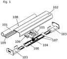
- the door comprises a fastening profile 100, a cover profile 101, a cover profile 102, two end caps 103, a first fastening element 104 with an external thread, a second fastening element 105 with an internal thread and a connecting element 106.
- the fastening profile 100 has a rail 107 on each of its sides whose longitudinal axes extend in the longitudinal direction of the fastening profile 100.
- the cover profile 101 has a band section 108 and a connecting section 109.
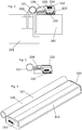
- the fastening profile 100 is fastened to a door leaf 202, which is fastened to a door frame 201 such that it can pivot via the door hinge 200.
- a door leaf 202 which is fastened to a door frame 201 such that it can pivot via the door hinge 200.
- the end caps are fastened to the fastening profile 100 by being pushed between the rails 107.
- the first fastening element 104 is also inserted between the rails and thus fastened to the fastening profile 100.
- the second fastening element 105 is connected to the connecting element 106, for example in a materially bonded manner. It is also possible for the second fastening element 105 and the connecting element 106 to be formed in one piece and / or in one piece.
- the connecting element 106 has a support surface with which it is supported on the fastening profile 100. A tilting movement of the connecting element 106 during an opening movement of the door leaf 202 is thus counteracted.
- the second fastening element 105 is screwed onto the first fastening element 104.
- the connecting section 109 of the cover profile 101 is arranged and fastened between two legs of the connecting element 106.
- a distance between the cover profile 101 and the door leaf 202 can thus be set in a direction perpendicular to one of the main surfaces of the door leaf 202.
- the combination of the first fastening element 104 and the second fastening element 105 can therefore also be referred to as a distance adjustment mechanism.
- the hinge section 108 has a circular cross-sectional area, the diameter of which is adapted to a diameter of the door hinge 200.
- the cover profile 102 is fastened to the fastening profile 100 and / or to the end caps 103. It covers the fastening profile 100, a first part of the connecting section 109, the distance adjustment mechanism 104 and 105 and the connecting element 106.
- a second part of the connecting section 109 and the band section 108 protrude laterally from the interior.
- the second part of the connecting section 109 protrudes through an opening between the fastening profile 100 and the cover profile 102.
- the distance between the cover profile 101 and the main surfaces of the door leaf 202 is set in such a way that the hinge section 108 is flush with the door hinge 200.
- a gap between the door frame 201 and the door leaf is thus at least partially covered by the cover profile 101, so that a human finger For example, a child's finger cannot be inserted into this gap on the hinge side. Since the cover profile 101 also projects into the interior space and is connected to the fastening profile 100, reliable finger protection is also achieved from a lateral direction.
- the position of the cover profile 101 can also be adapted by selecting the fastening position of the fastening profile 100 on the door leaf 202 both in a horizontal direction parallel to the main surfaces of the door leaf 202 and in the vertical direction to the position of the door hinge 200.
- the connecting element 106 can be freely displaced in the vertical direction within the rails 107. This also influences the vertical position of the cover profile 101. This is particularly advantageous in order to be able to arrange the fastening areas required for fastening the fastening profile 100 on the door leaf 202 so that they do not collide with the fastening areas for the door hinge 200 on the door leaf 202 during assembly. If, for example, both the door hinge 200 and the fastening profile 100 are fastened to the door leaf 202 with a screw connection, the respective screws in and on the door leaf 202 cannot cross one another.
- the complete band section 108 which is circular in cross section, is spaced apart from the fastening profile 100 in a horizontal direction parallel to the main surfaces of the door leaf 202.
- the finger protection mechanism can be designed to be particularly flat.
- the fastening profile 100 can be fastened to the door leaf 202, for example, even if the door hinge 200 is parallel to the horizontal direction Main surfaces of the door leaf 202 is spaced from the door leaf 202.
- a cable protrudes from the interior.
- the cable can, for example, protrude laterally and be guided through a recess in the band section 108 into a space surrounded by the band section 108.
- This cable can be used, for example, to supply an electrically operated device in the interior with electrical current and / or to conduct sensor data from a sensor arranged in the interior.
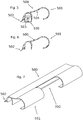
- the cover profile 500 is connected directly to the fastening profile 100 via a distance adjustment mechanism 503.
- the connecting element 106 is thus omitted.
- the cover profile 102 is also omitted, since the one-piece cover profile 500 covers the interior.
- the cover profile 500 also has a band section 501, which, however, has a partially circular cross-sectional area. However, here too the diameter is adapted to the diameter of the door hinge 200.
- the spacing adjustment mechanism 503 functions similarly or exactly as the spacing adjustment mechanism from FIGS Figures 1 to 4 .
- the cover profile 500 also has a gap cover 502, which is arranged on a side of the fastening profile 100 facing away from the band section 501.
- the gap cover 502 is elastically deformable and presses against the door leaf 202 when the fastening profile 100 is attached to the door leaf 202.
- the gap cover 502 presses against the door frame 201.
- the gap cover 502 extends over the entire length of the cover profile 501.
- the gap cover 502 limits together with it subsequent section of the cover profile 500 and the fastening profile 100, the interior space in which the distance adjustment mechanism 503 is arranged.
- the gap cover 502 covers a gap that may arise between the cover profile 500 and the attachment profile 100 as a function of the distance between the cover profile 500 and the fastening profile 100.
- the cover profile 500 at least partially covers the gap between the door leaf 202 and the door frame 201, so that a human finger, in particular a child's finger, cannot be inserted into the gap.
- the cover profile 504 has a break groove 504, the longitudinal axis of which runs parallel to the longitudinal axis of the cover profile 500.
- the breaking groove 504 is located adjacent to the band section 501.
- a partial area of the hinge section 501 in the area of the door hinge 200 can thus be broken out, which is defined by the breaking groove 504 and two incisions made with a cutting tool. In this way, a free space 700 is created in which the door hinge 200 is arranged when the cover profile 500 is mounted on the door.
- the hinge portion 501 is spaced apart from the fastening profile 100 in a horizontal direction parallel to the main surfaces of the door leaf 202 when the fastening profile 100 is fastened to the door leaf 202.
- a flat design of the Finger protection mechanism reached.
- an attachment of the finger protection mechanism to the door leaf 202 is also enabled, even if the door hinge 200 is spaced apart from the door leaf 202 in the horizontal direction parallel to the main surfaces of the door leaf 202.
- the embodiment of the Figures 5 to 7 differs in particular from the embodiment Figure 1 due to a reduced number of profiles, since the cover profile is no longer required.
- the breakable groove is advantageous because, due to the breakable groove 504, the partial area of the hinge section 501 required for the door hinge can be broken out with only two cuts.
Landscapes
- Engineering & Computer Science (AREA)
- Mechanical Engineering (AREA)
- Civil Engineering (AREA)
- Structural Engineering (AREA)
- Wing Frames And Configurations (AREA)
- Hinges (AREA)
Priority Applications (2)
| Application Number | Priority Date | Filing Date | Title |
|---|---|---|---|
| EP20213516.6A EP3783178B1 (fr) | 2020-12-11 | 2020-12-11 | Porte |
| ES20213516T ES2980561T3 (es) | 2020-12-11 | 2020-12-11 | Puerta |
Applications Claiming Priority (1)
| Application Number | Priority Date | Filing Date | Title |
|---|---|---|---|
| EP20213516.6A EP3783178B1 (fr) | 2020-12-11 | 2020-12-11 | Porte |
Publications (3)
| Publication Number | Publication Date |
|---|---|
| EP3783178A2 true EP3783178A2 (fr) | 2021-02-24 |
| EP3783178A3 EP3783178A3 (fr) | 2021-06-23 |
| EP3783178B1 EP3783178B1 (fr) | 2024-03-20 |
Family
ID=73834344
Family Applications (1)
| Application Number | Title | Priority Date | Filing Date |
|---|---|---|---|
| EP20213516.6A Active EP3783178B1 (fr) | 2020-12-11 | 2020-12-11 | Porte |
Country Status (2)
| Country | Link |
|---|---|
| EP (1) | EP3783178B1 (fr) |
| ES (1) | ES2980561T3 (fr) |
Citations (1)
| Publication number | Priority date | Publication date | Assignee | Title |
|---|---|---|---|---|
| DE202014101362U1 (de) | 2014-03-24 | 2015-06-26 | Athmer Ohg | Vorrichtung zur Abdeckung eines bandseitigen Spalts zwischen einer Tür und einem Türrahmen |
Family Cites Families (3)
| Publication number | Priority date | Publication date | Assignee | Title |
|---|---|---|---|---|
| DE102017100587A1 (de) * | 2017-01-13 | 2018-07-19 | Athmer Ohg | Befestigung eines Fingerschutzrollos zur Spaltüberdeckung |
| DE102019100645A1 (de) * | 2019-01-11 | 2020-07-16 | Hörmann Kg Ichtershausen | Klemmschutzsystem für Einfriedungs- und/oder Gebäudeabschlüsse, Anordnung mit Klemmschutzsystem, sowie Einfriedungs- und/oder Gebäudeabschluss |
| EP3767067B1 (fr) * | 2019-07-15 | 2024-11-20 | ASSA ABLOY (Schweiz) AG | Dispositif de protection de doigt côté paumelle |
-
2020
- 2020-12-11 EP EP20213516.6A patent/EP3783178B1/fr active Active
- 2020-12-11 ES ES20213516T patent/ES2980561T3/es active Active
Patent Citations (1)
| Publication number | Priority date | Publication date | Assignee | Title |
|---|---|---|---|---|
| DE202014101362U1 (de) | 2014-03-24 | 2015-06-26 | Athmer Ohg | Vorrichtung zur Abdeckung eines bandseitigen Spalts zwischen einer Tür und einem Türrahmen |
Also Published As
| Publication number | Publication date |
|---|---|
| ES2980561T3 (es) | 2024-10-02 |
| EP3783178B1 (fr) | 2024-03-20 |
| EP3783178A3 (fr) | 2021-06-23 |
Similar Documents
| Publication | Publication Date | Title |
|---|---|---|
| DE3532650C2 (fr) | ||
| EP1709267B1 (fr) | Fixation par clipsage pour le montage rapide de dispositifs d'armature, des fermetures a levier pivotant ou des pieces de charniere par exemple, dans des ouvertures menagees dans une paroi mince | |
| EP3258044B1 (fr) | Ensemble de battant et procédé de montage avant d'une partie de ferrure dans un tel ensemble de battant | |
| EP3344841B1 (fr) | Dispositif de protection de doigts au niveau des paumelles | |
| EP1857688B1 (fr) | Fixation par clipsage ou encliquetage permettant de fixer une paroi mince sur un support de paroi | |
| EP3535472B1 (fr) | Dispositif de protection des doigts | |
| EP3767067B1 (fr) | Dispositif de protection de doigt côté paumelle | |
| EP0478639B1 (fr) | Charniere | |
| EP1568833B1 (fr) | Gâche pour une fenêtre ou une porte | |
| EP3425155B1 (fr) | Dispositif de protection anti-pince doigt pour une porte | |
| DE3540766A1 (de) | Justierbares tuer- oder fensterband | |
| EP3783178B1 (fr) | Porte | |
| DE202016106504U1 (de) | Montagewerkzeug für die Montage einer Schaltschranktür an einem Schaltschrankgehäuse und eine entsprechende Schaltschrankanordnung | |
| EP3168394B1 (fr) | Piston de blocage pour dispositif d'ouverture de porte ou entrée de serrure | |
| EP3577295B1 (fr) | Mécanisme d'entrainement pour meuble servant à déplacer une partie de meuble montée mobile | |
| DE29817807U1 (de) | Dreidimensional verstellbares Aufschraubband für Tür- oder Fensterflügel | |
| EP3875728B1 (fr) | Module de connecteur de profil et cadre doté d'un module de connecteur de profil | |
| EP3757464B1 (fr) | Boîtier à suspendre au mur | |
| EP2740872B1 (fr) | Palier d'angle prévu pour l'agencement recouvert | |
| DE19856618C2 (de) | Vorrichtung zum Führen eines verschiebbaren Verschlußelements | |
| EP1344478B1 (fr) | Cabine de douche avec au moins une cloison de verre | |
| DE3145375C2 (de) | Mehrteiliges Rahmenprofil | |
| EP1777363B1 (fr) | Dispositif d'arrêt pour une porte d'un boîtier | |
| DE2460943A1 (de) | Moebelscharnier | |
| WO2019161424A1 (fr) | Support de montage pour rails de guidage |
Legal Events
| Date | Code | Title | Description |
|---|---|---|---|
| PUAI | Public reference made under article 153(3) epc to a published international application that has entered the european phase |
Free format text: ORIGINAL CODE: 0009012 |
|
| STAA | Information on the status of an ep patent application or granted ep patent |
Free format text: STATUS: THE APPLICATION HAS BEEN PUBLISHED |
|
| AK | Designated contracting states |
Kind code of ref document: A2 Designated state(s): AL AT BE BG CH CY CZ DE DK EE ES FI FR GB GR HR HU IE IS IT LI LT LU LV MC MK MT NL NO PL PT RO RS SE SI SK SM TR |
|
| AX | Request for extension of the european patent |
Extension state: BA ME |
|
| RIN1 | Information on inventor provided before grant (corrected) |
Inventor name: HECKMANN, ANDRE |
|
| PUAL | Search report despatched |
Free format text: ORIGINAL CODE: 0009013 |
|
| AK | Designated contracting states |
Kind code of ref document: A3 Designated state(s): AL AT BE BG CH CY CZ DE DK EE ES FI FR GB GR HR HU IE IS IT LI LT LU LV MC MK MT NL NO PL PT RO RS SE SI SK SM TR |
|
| RIC1 | Information provided on ipc code assigned before grant |
Ipc: E05D 5/04 20060101AFI20210520BHEP Ipc: E05D 11/00 20060101ALI20210520BHEP Ipc: E06B 7/36 20060101ALI20210520BHEP |
|
| STAA | Information on the status of an ep patent application or granted ep patent |
Free format text: STATUS: REQUEST FOR EXAMINATION WAS MADE |
|
| 17P | Request for examination filed |
Effective date: 20211223 |
|
| RBV | Designated contracting states (corrected) |
Designated state(s): AL AT BE BG CH CY CZ DE DK EE ES FI FR GB GR HR HU IE IS IT LI LT LU LV MC MK MT NL NO PL PT RO RS SE SI SK SM TR |
|
| STAA | Information on the status of an ep patent application or granted ep patent |
Free format text: STATUS: EXAMINATION IS IN PROGRESS |
|
| 17Q | First examination report despatched |
Effective date: 20220429 |
|
| GRAP | Despatch of communication of intention to grant a patent |
Free format text: ORIGINAL CODE: EPIDOSNIGR1 |
|
| STAA | Information on the status of an ep patent application or granted ep patent |
Free format text: STATUS: GRANT OF PATENT IS INTENDED |
|
| INTG | Intention to grant announced |
Effective date: 20231006 |
|
| GRAS | Grant fee paid |
Free format text: ORIGINAL CODE: EPIDOSNIGR3 |
|
| GRAA | (expected) grant |
Free format text: ORIGINAL CODE: 0009210 |
|
| STAA | Information on the status of an ep patent application or granted ep patent |
Free format text: STATUS: THE PATENT HAS BEEN GRANTED |
|
| AK | Designated contracting states |
Kind code of ref document: B1 Designated state(s): AL AT BE BG CH CY CZ DE DK EE ES FI FR GB GR HR HU IE IS IT LI LT LU LV MC MK MT NL NO PL PT RO RS SE SI SK SM TR |
|
| REG | Reference to a national code |
Ref country code: GB Ref legal event code: FG4D Free format text: NOT ENGLISH |
|
| REG | Reference to a national code |
Ref country code: CH Ref legal event code: EP |
|
| REG | Reference to a national code |
Ref country code: DE Ref legal event code: R096 Ref document number: 502020007397 Country of ref document: DE |
|
| REG | Reference to a national code |
Ref country code: IE Ref legal event code: FG4D Free format text: LANGUAGE OF EP DOCUMENT: GERMAN |
|
| REG | Reference to a national code |
Ref country code: SE Ref legal event code: TRGR |
|
| PG25 | Lapsed in a contracting state [announced via postgrant information from national office to epo] |
Ref country code: LT Free format text: LAPSE BECAUSE OF FAILURE TO SUBMIT A TRANSLATION OF THE DESCRIPTION OR TO PAY THE FEE WITHIN THE PRESCRIBED TIME-LIMIT Effective date: 20240320 |
|
| REG | Reference to a national code |
Ref country code: LT Ref legal event code: MG9D |
|
| PG25 | Lapsed in a contracting state [announced via postgrant information from national office to epo] |
Ref country code: GR Free format text: LAPSE BECAUSE OF FAILURE TO SUBMIT A TRANSLATION OF THE DESCRIPTION OR TO PAY THE FEE WITHIN THE PRESCRIBED TIME-LIMIT Effective date: 20240621 |
|
| REG | Reference to a national code |
Ref country code: NL Ref legal event code: FP |
|
| PG25 | Lapsed in a contracting state [announced via postgrant information from national office to epo] |
Ref country code: HR Free format text: LAPSE BECAUSE OF FAILURE TO SUBMIT A TRANSLATION OF THE DESCRIPTION OR TO PAY THE FEE WITHIN THE PRESCRIBED TIME-LIMIT Effective date: 20240320 Ref country code: RS Free format text: LAPSE BECAUSE OF FAILURE TO SUBMIT A TRANSLATION OF THE DESCRIPTION OR TO PAY THE FEE WITHIN THE PRESCRIBED TIME-LIMIT Effective date: 20240620 |
|
| PG25 | Lapsed in a contracting state [announced via postgrant information from national office to epo] |
Ref country code: RS Free format text: LAPSE BECAUSE OF FAILURE TO SUBMIT A TRANSLATION OF THE DESCRIPTION OR TO PAY THE FEE WITHIN THE PRESCRIBED TIME-LIMIT Effective date: 20240620 Ref country code: NO Free format text: LAPSE BECAUSE OF FAILURE TO SUBMIT A TRANSLATION OF THE DESCRIPTION OR TO PAY THE FEE WITHIN THE PRESCRIBED TIME-LIMIT Effective date: 20240620 Ref country code: LT Free format text: LAPSE BECAUSE OF FAILURE TO SUBMIT A TRANSLATION OF THE DESCRIPTION OR TO PAY THE FEE WITHIN THE PRESCRIBED TIME-LIMIT Effective date: 20240320 Ref country code: HR Free format text: LAPSE BECAUSE OF FAILURE TO SUBMIT A TRANSLATION OF THE DESCRIPTION OR TO PAY THE FEE WITHIN THE PRESCRIBED TIME-LIMIT Effective date: 20240320 Ref country code: GR Free format text: LAPSE BECAUSE OF FAILURE TO SUBMIT A TRANSLATION OF THE DESCRIPTION OR TO PAY THE FEE WITHIN THE PRESCRIBED TIME-LIMIT Effective date: 20240621 Ref country code: FI Free format text: LAPSE BECAUSE OF FAILURE TO SUBMIT A TRANSLATION OF THE DESCRIPTION OR TO PAY THE FEE WITHIN THE PRESCRIBED TIME-LIMIT Effective date: 20240320 Ref country code: BG Free format text: LAPSE BECAUSE OF FAILURE TO SUBMIT A TRANSLATION OF THE DESCRIPTION OR TO PAY THE FEE WITHIN THE PRESCRIBED TIME-LIMIT Effective date: 20240320 |
|
| PG25 | Lapsed in a contracting state [announced via postgrant information from national office to epo] |
Ref country code: LV Free format text: LAPSE BECAUSE OF FAILURE TO SUBMIT A TRANSLATION OF THE DESCRIPTION OR TO PAY THE FEE WITHIN THE PRESCRIBED TIME-LIMIT Effective date: 20240320 |
|
| REG | Reference to a national code |
Ref country code: ES Ref legal event code: FG2A Ref document number: 2980561 Country of ref document: ES Kind code of ref document: T3 Effective date: 20241002 |
|
| PG25 | Lapsed in a contracting state [announced via postgrant information from national office to epo] |
Ref country code: IS Free format text: LAPSE BECAUSE OF FAILURE TO SUBMIT A TRANSLATION OF THE DESCRIPTION OR TO PAY THE FEE WITHIN THE PRESCRIBED TIME-LIMIT Effective date: 20240720 |
|
| PG25 | Lapsed in a contracting state [announced via postgrant information from national office to epo] |
Ref country code: PT Free format text: LAPSE BECAUSE OF FAILURE TO SUBMIT A TRANSLATION OF THE DESCRIPTION OR TO PAY THE FEE WITHIN THE PRESCRIBED TIME-LIMIT Effective date: 20240722 Ref country code: SM Free format text: LAPSE BECAUSE OF FAILURE TO SUBMIT A TRANSLATION OF THE DESCRIPTION OR TO PAY THE FEE WITHIN THE PRESCRIBED TIME-LIMIT Effective date: 20240320 |
|
| PG25 | Lapsed in a contracting state [announced via postgrant information from national office to epo] |
Ref country code: EE Free format text: LAPSE BECAUSE OF FAILURE TO SUBMIT A TRANSLATION OF THE DESCRIPTION OR TO PAY THE FEE WITHIN THE PRESCRIBED TIME-LIMIT Effective date: 20240320 Ref country code: CZ Free format text: LAPSE BECAUSE OF FAILURE TO SUBMIT A TRANSLATION OF THE DESCRIPTION OR TO PAY THE FEE WITHIN THE PRESCRIBED TIME-LIMIT Effective date: 20240320 |
|
| PG25 | Lapsed in a contracting state [announced via postgrant information from national office to epo] |
Ref country code: PL Free format text: LAPSE BECAUSE OF FAILURE TO SUBMIT A TRANSLATION OF THE DESCRIPTION OR TO PAY THE FEE WITHIN THE PRESCRIBED TIME-LIMIT Effective date: 20240320 |
|
| PG25 | Lapsed in a contracting state [announced via postgrant information from national office to epo] |
Ref country code: SK Free format text: LAPSE BECAUSE OF FAILURE TO SUBMIT A TRANSLATION OF THE DESCRIPTION OR TO PAY THE FEE WITHIN THE PRESCRIBED TIME-LIMIT Effective date: 20240320 |
|
| PG25 | Lapsed in a contracting state [announced via postgrant information from national office to epo] |
Ref country code: SM Free format text: LAPSE BECAUSE OF FAILURE TO SUBMIT A TRANSLATION OF THE DESCRIPTION OR TO PAY THE FEE WITHIN THE PRESCRIBED TIME-LIMIT Effective date: 20240320 Ref country code: SK Free format text: LAPSE BECAUSE OF FAILURE TO SUBMIT A TRANSLATION OF THE DESCRIPTION OR TO PAY THE FEE WITHIN THE PRESCRIBED TIME-LIMIT Effective date: 20240320 Ref country code: RO Free format text: LAPSE BECAUSE OF FAILURE TO SUBMIT A TRANSLATION OF THE DESCRIPTION OR TO PAY THE FEE WITHIN THE PRESCRIBED TIME-LIMIT Effective date: 20240320 Ref country code: PT Free format text: LAPSE BECAUSE OF FAILURE TO SUBMIT A TRANSLATION OF THE DESCRIPTION OR TO PAY THE FEE WITHIN THE PRESCRIBED TIME-LIMIT Effective date: 20240722 Ref country code: PL Free format text: LAPSE BECAUSE OF FAILURE TO SUBMIT A TRANSLATION OF THE DESCRIPTION OR TO PAY THE FEE WITHIN THE PRESCRIBED TIME-LIMIT Effective date: 20240320 Ref country code: IS Free format text: LAPSE BECAUSE OF FAILURE TO SUBMIT A TRANSLATION OF THE DESCRIPTION OR TO PAY THE FEE WITHIN THE PRESCRIBED TIME-LIMIT Effective date: 20240720 Ref country code: EE Free format text: LAPSE BECAUSE OF FAILURE TO SUBMIT A TRANSLATION OF THE DESCRIPTION OR TO PAY THE FEE WITHIN THE PRESCRIBED TIME-LIMIT Effective date: 20240320 Ref country code: CZ Free format text: LAPSE BECAUSE OF FAILURE TO SUBMIT A TRANSLATION OF THE DESCRIPTION OR TO PAY THE FEE WITHIN THE PRESCRIBED TIME-LIMIT Effective date: 20240320 |
|
| REG | Reference to a national code |
Ref country code: DE Ref legal event code: R097 Ref document number: 502020007397 Country of ref document: DE |
|
| PG25 | Lapsed in a contracting state [announced via postgrant information from national office to epo] |
Ref country code: DK Free format text: LAPSE BECAUSE OF FAILURE TO SUBMIT A TRANSLATION OF THE DESCRIPTION OR TO PAY THE FEE WITHIN THE PRESCRIBED TIME-LIMIT Effective date: 20240320 |
|
| P01 | Opt-out of the competence of the unified patent court (upc) registered |
Free format text: CASE NUMBER: APP_65924/2024 Effective date: 20241213 |
|
| PLBE | No opposition filed within time limit |
Free format text: ORIGINAL CODE: 0009261 |
|
| STAA | Information on the status of an ep patent application or granted ep patent |
Free format text: STATUS: NO OPPOSITION FILED WITHIN TIME LIMIT |
|
| PG25 | Lapsed in a contracting state [announced via postgrant information from national office to epo] |
Ref country code: DK Free format text: LAPSE BECAUSE OF FAILURE TO SUBMIT A TRANSLATION OF THE DESCRIPTION OR TO PAY THE FEE WITHIN THE PRESCRIBED TIME-LIMIT Effective date: 20240320 |
|
| 26N | No opposition filed |
Effective date: 20241223 |
|
| PG25 | Lapsed in a contracting state [announced via postgrant information from national office to epo] |
Ref country code: SI Free format text: LAPSE BECAUSE OF FAILURE TO SUBMIT A TRANSLATION OF THE DESCRIPTION OR TO PAY THE FEE WITHIN THE PRESCRIBED TIME-LIMIT Effective date: 20240320 |
|
| PG25 | Lapsed in a contracting state [announced via postgrant information from national office to epo] |
Ref country code: MC Free format text: LAPSE BECAUSE OF FAILURE TO SUBMIT A TRANSLATION OF THE DESCRIPTION OR TO PAY THE FEE WITHIN THE PRESCRIBED TIME-LIMIT Effective date: 20240320 |
|
| PG25 | Lapsed in a contracting state [announced via postgrant information from national office to epo] |
Ref country code: LU Free format text: LAPSE BECAUSE OF NON-PAYMENT OF DUE FEES Effective date: 20241211 |
|
| REG | Reference to a national code |
Ref country code: BE Ref legal event code: MM Effective date: 20241231 |
|
| PG25 | Lapsed in a contracting state [announced via postgrant information from national office to epo] |
Ref country code: BE Free format text: LAPSE BECAUSE OF NON-PAYMENT OF DUE FEES Effective date: 20241231 |
|
| PG25 | Lapsed in a contracting state [announced via postgrant information from national office to epo] |
Ref country code: IE Free format text: LAPSE BECAUSE OF NON-PAYMENT OF DUE FEES Effective date: 20241211 |
|
| REG | Reference to a national code |
Ref country code: CH Ref legal event code: U11 Free format text: ST27 STATUS EVENT CODE: U-0-0-U10-U11 (AS PROVIDED BY THE NATIONAL OFFICE) Effective date: 20260101 |
|
| PGFP | Annual fee paid to national office [announced via postgrant information from national office to epo] |
Ref country code: GB Payment date: 20251219 Year of fee payment: 6 |
|
| PGFP | Annual fee paid to national office [announced via postgrant information from national office to epo] |
Ref country code: AT Payment date: 20251222 Year of fee payment: 6 |
|
| PGFP | Annual fee paid to national office [announced via postgrant information from national office to epo] |
Ref country code: IT Payment date: 20251222 Year of fee payment: 6 |
|
| PGFP | Annual fee paid to national office [announced via postgrant information from national office to epo] |
Ref country code: NL Payment date: 20251219 Year of fee payment: 6 Ref country code: FR Payment date: 20251229 Year of fee payment: 6 |
|
| PGFP | Annual fee paid to national office [announced via postgrant information from national office to epo] |
Ref country code: SE Payment date: 20251219 Year of fee payment: 6 |
|
| PGFP | Annual fee paid to national office [announced via postgrant information from national office to epo] |
Ref country code: ES Payment date: 20260130 Year of fee payment: 6 |
|
| PGFP | Annual fee paid to national office [announced via postgrant information from national office to epo] |
Ref country code: DE Payment date: 20251231 Year of fee payment: 6 |
|
| PGFP | Annual fee paid to national office [announced via postgrant information from national office to epo] |
Ref country code: CH Payment date: 20260101 Year of fee payment: 6 |