EP3783266A1 - Appareil de cuisson doté d'un compartiment de cuisson pouvant être fermé et son procédé de fonctionnement - Google Patents
Appareil de cuisson doté d'un compartiment de cuisson pouvant être fermé et son procédé de fonctionnement Download PDFInfo
- Publication number
- EP3783266A1 EP3783266A1 EP20190665.8A EP20190665A EP3783266A1 EP 3783266 A1 EP3783266 A1 EP 3783266A1 EP 20190665 A EP20190665 A EP 20190665A EP 3783266 A1 EP3783266 A1 EP 3783266A1
- Authority
- EP
- European Patent Office
- Prior art keywords
- door
- drive unit
- force
- cooking
- closed position
- Prior art date
- Legal status (The legal status is an assumption and is not a legal conclusion. Google has not performed a legal analysis and makes no representation as to the accuracy of the status listed.)
- Granted
Links
Images






Classifications
-
- F—MECHANICAL ENGINEERING; LIGHTING; HEATING; WEAPONS; BLASTING
- F24—HEATING; RANGES; VENTILATING
- F24C—DOMESTIC STOVES OR RANGES ; DETAILS OF DOMESTIC STOVES OR RANGES, OF GENERAL APPLICATION
- F24C15/00—Details
- F24C15/02—Doors specially adapted for stoves or ranges
- F24C15/023—Mounting of doors, e.g. hinges, counterbalancing
-
- E—FIXED CONSTRUCTIONS
- E05—LOCKS; KEYS; WINDOW OR DOOR FITTINGS; SAFES
- E05F—DEVICES FOR MOVING WINGS INTO OPEN OR CLOSED POSITION; CHECKS FOR WINGS; WING FITTINGS NOT OTHERWISE PROVIDED FOR, CONCERNED WITH THE FUNCTIONING OF THE WING
- E05F15/00—Power-operated mechanisms for wings
- E05F15/60—Power-operated mechanisms for wings using electrical actuators
- E05F15/603—Power-operated mechanisms for wings using electrical actuators using rotary electromotors
- E05F15/611—Power-operated mechanisms for wings using electrical actuators using rotary electromotors for swinging wings
-
- E—FIXED CONSTRUCTIONS
- E05—LOCKS; KEYS; WINDOW OR DOOR FITTINGS; SAFES
- E05Y—INDEXING SCHEME ASSOCIATED WITH SUBCLASSES E05D AND E05F, RELATING TO CONSTRUCTION ELEMENTS, ELECTRIC CONTROL, POWER SUPPLY, POWER SIGNAL OR TRANSMISSION, USER INTERFACES, MOUNTING OR COUPLING, DETAILS, ACCESSORIES, AUXILIARY OPERATIONS NOT OTHERWISE PROVIDED FOR, APPLICATION THEREOF
- E05Y2201/00—Constructional elements; Accessories therefor
- E05Y2201/20—Brakes; Disengaging means; Holders; Stops; Valves; Accessories therefor
- E05Y2201/218—Holders
-
- E—FIXED CONSTRUCTIONS
- E05—LOCKS; KEYS; WINDOW OR DOOR FITTINGS; SAFES
- E05Y—INDEXING SCHEME ASSOCIATED WITH SUBCLASSES E05D AND E05F, RELATING TO CONSTRUCTION ELEMENTS, ELECTRIC CONTROL, POWER SUPPLY, POWER SIGNAL OR TRANSMISSION, USER INTERFACES, MOUNTING OR COUPLING, DETAILS, ACCESSORIES, AUXILIARY OPERATIONS NOT OTHERWISE PROVIDED FOR, APPLICATION THEREOF
- E05Y2201/00—Constructional elements; Accessories therefor
- E05Y2201/40—Motors; Magnets; Springs; Weights; Accessories therefor
- E05Y2201/404—Function thereof
- E05Y2201/418—Function thereof for holding
-
- E—FIXED CONSTRUCTIONS
- E05—LOCKS; KEYS; WINDOW OR DOOR FITTINGS; SAFES
- E05Y—INDEXING SCHEME ASSOCIATED WITH SUBCLASSES E05D AND E05F, RELATING TO CONSTRUCTION ELEMENTS, ELECTRIC CONTROL, POWER SUPPLY, POWER SIGNAL OR TRANSMISSION, USER INTERFACES, MOUNTING OR COUPLING, DETAILS, ACCESSORIES, AUXILIARY OPERATIONS NOT OTHERWISE PROVIDED FOR, APPLICATION THEREOF
- E05Y2900/00—Application of doors, windows, wings or fittings thereof
- E05Y2900/30—Application of doors, windows, wings or fittings thereof for domestic appliances
-
- E—FIXED CONSTRUCTIONS
- E05—LOCKS; KEYS; WINDOW OR DOOR FITTINGS; SAFES
- E05Y—INDEXING SCHEME ASSOCIATED WITH SUBCLASSES E05D AND E05F, RELATING TO CONSTRUCTION ELEMENTS, ELECTRIC CONTROL, POWER SUPPLY, POWER SIGNAL OR TRANSMISSION, USER INTERFACES, MOUNTING OR COUPLING, DETAILS, ACCESSORIES, AUXILIARY OPERATIONS NOT OTHERWISE PROVIDED FOR, APPLICATION THEREOF
- E05Y2900/00—Application of doors, windows, wings or fittings thereof
- E05Y2900/30—Application of doors, windows, wings or fittings thereof for domestic appliances
- E05Y2900/308—Application of doors, windows, wings or fittings thereof for domestic appliances for ovens
Definitions
- the invention relates to a cooking device, comprising a housing, a cooking space arranged in the housing with a cooking space opening and a door assigned to the cooking space opening, as well as a method for operating this cooking device.
- the known cooking devices include a housing, a cooking space arranged in the housing with a cooking space opening and a door assigned to the cooking space opening, the door being movable in a range of motion between a closed position and an open position of the door, and the cooking space being locked in the closed position of the door and is accessible when the door is open.
- the invention thus poses the problem of specifying a cooking device comprising a housing, a cooking space arranged in the housing with a cooking space opening and a door assigned to the cooking space opening, as well as a method for its operation in which the door operating mechanism and the door operating are improved.
- a cooking device comprising a housing, a cooking space arranged in the housing with a cooking space opening and a door assigned to the cooking space opening, with the features of claim 1, which is characterized in that a first drive unit and a second drive units are each arranged for the automatic movement of the door, the door being movable by means of the first drive unit in a first movement section of the movement area and by means of the second drive unit in a second movement section of the movement area of the door, preferably depending on the transfer of the door into its open position or in their closed position.
- the advantage that can be achieved with the invention is, in particular, that in a cooking device comprising a housing, a cooking space arranged in the housing with a cooking space opening and a door assigned to the cooking space opening, as well as in a method for its operation, the door operating mechanism and the door operating are improved.
- a cooking space opening of the cooking space can be tightly closed by means of the door, for example during a cooking process.
- a cleaning process taking place in the cooking space such as pyrolytic cleaning of the cooking space or the like.
- the door can be moved depending on the transfer of the door in its open position or in its closed position by means of the first drive unit in a first movement section of the movement area and by means of the second drive unit in a second movement section of the movement area of the door, the Particularities when moving the door into its open position and into its closed position are taken into account in an advantageous manner.
- the above-mentioned high pressing force is only required when moving the door when it is moved into its closed position.
- the door can be moved and moved not only in the second movement section by means of the second drive unit, but also in the first movement section, namely when the door is moved into its open position.
- this embodiment of the invention is to be understood purely as an example.
- the design of the door operating mechanism can be freely selected within wide, suitable limits.
- An advantageous further development of the cooking appliance according to the invention provides that the door is arranged pivotably about an axis of rotation arranged on the housing, wherein the first drive unit is arranged on the housing on a side of the cooking chamber opening opposite the axis of rotation and the second drive unit is connected to the door in a force-transmitting manner on the axis of rotation. In this way, for example, the effort required to move the door into its closed position is reduced, so that the first drive unit can be motorized more weakly and thus more cost-effectively.
- the first drive unit has a base plate and a slide, the first drive unit being fastened to the housing by means of the base plate and the slide being held movably on the base plate.
- the first drive unit is implemented in a structurally particularly simple manner.
- a particularly advantageous development of the aforementioned embodiment of the cooking device according to the invention provides that the slide has a base part assigned to the base plate and an actuation part assigned to the door, the base part and the actuation part being resiliently connected to one another.
- tolerance compensation is made possible in a simple and robust manner.
- an electric motor of the first drive unit is effectively protected against undesired mechanical stress.
- a further advantageous development of the cooking appliance according to the invention provides that the door and the first drive unit have coupling means that correspond to one another, the door and the first drive unit being able to be coupled in a force-transmitting manner by means of these coupling means.
- the power transmission between the door on the one hand and the first drive unit on the other hand is realized without additional components.
- a particularly advantageous further development of the aforementioned embodiment of the cooking device according to the invention referring back to claim 3 or 4, provides that a coupling means designed as a hook is arranged on the carriage, which can be moved back and forth between an actuating position and a non-actuating position, the door in the actuating position of the hook can be connected to the hook in a force-transmitting manner and cannot be connected to the hook in a force-transmitting manner in the non-actuating position of the hook.
- the coupling means of the first drive unit is implemented in a structurally particularly simple and robust manner.
- the first drive unit is designed at the same time as a locking unit for holding the door in its closed position. In this way it is possible to hold the door in its closed position by means of the first drive unit. An additional locking unit to hold the door is not required.
- the hook is designed at the same time as a locking hook for holding the door in its closed position.
- the locking unit in particular the hook and the undercut, can advantageously be designed in such a way that there is a frictional connection, but not a positive connection.
- the door can therefore be torn open even if there is a hook in the closed position. There is therefore no locking by the locking unit.
- a locking of the door in its closed position is necessary, for example, when the cooking device according to the invention is in pyrolysis mode and can be implemented by a separate locking unit.
- Another particularly advantageous development of the cooking appliance according to the invention provides that the first drive unit and the second drive unit are each connected to the door in a force-transmitting manner for the automatic movement of the door by means of a common coupling device. Due to this development of the cooking device and the method for its operation, according to which the first and the second drive unit are each connected to the door by means of a common coupling device for the automatic movement of the door, and the first drive unit and the second drive unit are each connected to the door by means of this common coupling device move automatically, a particularly simple and thus inexpensive design of the cooking device is made possible.
- An advantageous development of the aforementioned embodiment of the cooking device according to the invention provides that the door is arranged pivotably about an axis of rotation arranged on the housing, the first drive unit and the second drive unit being connected to the door in a force-transmitting manner by means of the coupling device on the rotational axis side.
- the cooking appliance according to the invention can thus be implemented in a component-saving manner.
- the first drive unit has a force introduction device, the force introduction device between an engagement position in which the force introduction device is in force-transmitting engagement with the coupling device, and a non-engagement position in which the force introduction device is not in force-transmitting engagement with the coupling device, can be transferred back and forth. This makes it possible to connect the first drive unit to the coupling device in a force-transmitting manner by means of the force introduction device or to release this force transmission connection.
- the first drive unit can, for example, be connected to the coupling device in a force-transmitting manner by means of the force introduction device only in the event that the above-mentioned high pressing force of the door is required for a tight closure of the cooking chamber opening of the cooking chamber. Otherwise, the first drive unit can be decoupled from the coupling device in the aforementioned manner, so that any other movement of the door, manually or automatically, is significantly facilitated.
- the first drive unit has a force introduction device, the force introduction device between an engagement position in which the force introduction device is in force-transmitting engagement with the coupling device, and a non-engagement position in which the force introduction device does not transmit force with the coupling device is engaged, is transferred back and forth.
- the first drive unit additionally has a motor, an eccentric connected to the motor in a torque-transmitting manner, and a slide, the slide being resiliently mounted on the housing by means of at least one return spring in such a way that the The force introduction device mounted on the slide can be automatically transferred from its engagement position to its non-engagement position by means of the return spring, and the motor, the eccentric and the slide are designed and arranged in relation to one another in such a way that the force introduction device mounted on the slide by means of the motor, the eccentric and the slide from their non-engagement position can be automatically transferred into their engagement position.
- the first drive unit can be implemented in a particularly simple manner in terms of design and manufacturing technology.
- the carriage can be mounted directly or indirectly on the housing.
- the first drive unit and / or the second drive unit are / is at least partially designed as an assembly which is then connected as a whole to the housing in a force-transmitting manner.
- the slide can be resiliently mounted on a mounting plate or the like of this assembly.
- the force introduction device is resiliently mounted on the slide by means of at least one force introduction spring, a range of movement of the Force introduction device is limited relative to the slide by means of mutually corresponding limiting means of the force introduction device and the slide.
- This enables the force introduction device arranged on the slide to rest resiliently on the coupling device in the engagement position of the force introduction device.
- the door can be moved manually from its closed position to its open position against a spring force of the force introduction spring, for example by a user of the cooking appliance.
- the coupling device has a coupling link
- the force introduction device of the first drive unit in its engagement position by means of the coupling link is in engagement with the coupling device, preferably that the coupling link has a coupling link bevel to divert a by means of the Having force introduction device in the coupling device introduced force.
- the structural design of the cooking appliance according to the invention is further simplified.
- the preferred embodiment of this development has the additional advantage that the force introduced into the coupling device by means of the force introduction device can be diverted in a simple and robust manner by means of the bevel of the coupling link.
- the first drive unit can be arranged more flexibly and freely relative to the coupling device, so that the installation space present in the respective cooking appliance according to the invention can be used adapted to the requirements of the individual case.
- the coupling device has a control link, the control link being designed to actuate at least one switch connected to a control of the cooking device in a signal-transmitting manner, preferably that a plurality of can be operated by switches, whereby the open position of the door, the closed position of the door and an intermediate position of the door can be detected by means of the individual switches, and the first movement section between the intermediate position and the closed position of the door and the second movement section between the intermediate position and the open position the door is formed.
- the coupling device has a control link, the control link being designed to actuate at least one switch connected to a control of the cooking device in a signal-transmitting manner, preferably that a plurality of can be operated by switches, whereby the open position of the door, the closed position of the door and an intermediate position of the door can be detected by means of the individual switches, and the first movement section between the intermediate position and the closed position of the door and the second movement section between the intermediate position and the open position the door is formed.
- the preferred embodiment of this development is particularly advantageous, since among other things the positions of the door which are important for the control of the first and the second drive unit for the automatic movement of the door can be detected.
- the aforementioned detection of the at least one position of the door can of course also be used for other functions of the cooking appliance, for example for cooking functions or a pyrolysis function of the cooking appliance, in the control of the cooking appliance.
- An advantageous development of the last-mentioned embodiment of the cooking device according to the invention provides that the force application device of the first drive unit can be transferred from its engagement position into its non-engagement position and / or from its non-engagement position into its engagement position depending on the detection of the intermediate layer.
- the control of the first drive unit by means of the control of the cooking appliance is implemented in a particularly obvious way.
- the intermediate layer is designed as the position of the door in which the door is in contact with a sealing device surrounding the cooking chamber opening, i.e. in contact with the aforementioned sealing device without significantly compressing this sealing device.
- the force application device of the first drive unit can then be transferred from its non-engagement position into its engagement position, so that the door is firmly against by means of the first drive unit and the coupling device the aforementioned sealing device is pressed, namely in such a way that the cooking chamber opening is essentially tightly closed by means of the door and the sealing device.
- a further advantageous development of the method according to the invention provides that the force application device of the first drive unit is transferred from its engagement position into its non-engagement position and / or from its non-engagement position into its engagement position, the intermediate position of the door between the closed position and the opening position of the door is positioned.
- the first movement section is positioned on the closing position side and the second movement section is positioned on the opening position side.
- a high actuating force for example a pressing force for tight contact of the door with the sealing device mentioned above, is required when the door is actuated, particularly when moving the door into its closed position. Accordingly, it is advantageous to carry out a change in the actuation of the door from the second drive unit to the first drive unit for the corresponding movement section in the movement area of the door.
- the door is automatically transferred into at least one intermediate position of the door by means of the first drive unit and / or the second drive unit and is held in this intermediate position, the intermediate position of the door between the closed position and the open position of the Door is positioned.
- the door is not just between its closed position and whose opening position can be automatically transferred back and forth. Instead, the door can also occupy at least one intermediate position between its closed position and its open position.
- the at least one intermediate layer of the door can be freely selected within wide, suitable limits.
- a particularly advantageous development of the method according to the invention provides that an automatic program for rapid cooling of the cooking chamber is stored in a control of the cooking device, the door being automatically transferred to an intermediate layer corresponding to this automatic program when the automatic program is executed. This enables a rapid cooling function in the cooking device according to the invention without additional structural effort.
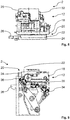
- the cooking device 2 is designed as a domestic oven and comprises a housing 4, a cooking space 6 arranged in the housing 4 with a cooking space opening 8 and a door 10 assigned to the cooking space opening 8, the door 10 being in a range of movement between one in the Fig. 3 shown closed position and one in the Fig. 1 illustrated opening position of the door 10 is movable.
- the cooking chamber 6 is closed in the closed position of the door 10 and accessible in the open position of the door 10, a first drive unit 12 and a second drive unit 14 each being arranged on the housing 4 for the automatic movement of the door 10, the door 10 by means of the first drive unit 12 is movable in a first movement section of the movement range and by means of the second drive unit 14 in a second movement section of the movement range of the door 10.
- the door 10 is depending on the transfer of the door 10 in its open position or in its closed position by means of the first drive unit 12 in the first movement section of the movement area and by means of the second drive unit 14 in the second movement section of the movement area
- Door 10 movable, which will be explained in more detail below.
- the door 10 is arranged to be pivotable about an axis of rotation 16 arranged on the housing 4, the first drive unit 12 being arranged on the housing 4 on a side of the cooking chamber opening 8 opposite the axis of rotation 16 and the second drive unit 14 being connected to the door 10 in a force-transmitting manner on the axis of rotation . See the Figs. 1 and 2 .
- the first movement section of the door 10 ranges from 0 ° to approximately 3 ° door opening, with 0 ° door opening to that in FIG Fig. 3 illustrated closed position of the door 10 corresponds.
- the second movement section of the door 10 ranges from about 3 ° to about 85 ° door opening, with 85 ° door opening to that in the Fig. 1 illustrated opening position of the door 10 corresponds.
- the first movement section is positioned on the closing position side and the second movement section is positioned on the opening position side.
- the door 10 can be moved automatically by means of the first drive unit 12.
- the door 10 can be automatically moved by means of the second drive unit 14 in the first movement section and in the second movement section.
- the first drive unit 12 has a base plate 18 and a slide 20, the first drive unit 12 being fastened to the housing 4 by means of the base plate 18 and the slide 20 being movably held on the base plate 18. See the Figs. 1 to 12 in the synopsis.
- the slide 20 has a base part 22 associated with the base plate 18 and an actuation part 24 associated with the door 10, the base part 22 and the actuation part 24 being resiliently connected to one another. See also the Figs. 1 to 12 in the synopsis.
- the carriage 20 is as a whole, so base part 22 and actuating part 24, by means of an electric motor 25 between one in the Figs. 2 to 5 and 8th to 12 shown rest position and one in the Figures 6, 7a and 7b shown gripping position can be moved back and forth.
- the door 10 and the first drive unit 12 have coupling means 26, 28 which correspond to one another, the door 10 and the first drive unit 12 being able to be coupled in a force-transmitting manner by means of these coupling means 26, 28.
- the coupling means 26 is designed as a hook and is arranged on the actuating part 24 of the slide 22.
- the hook 26 can be moved back and forth between an actuating position and a non-actuating position, the door 10 being connectable to the hook 26 in a force-transmitting manner in the actuating position of the hook 26 and non-force-transmittingly connectable to the hook 26 in the non-actuating position of the hook 26.
- the operating position of the hook 26 is in the Fig.
- the non-actuated position of the hook 26 is in the Figures 4 and 5 shown.
- the hook 26 by means of the door 10 when it is moved from its open position to its closed position against the spring force of a spring element, not shown, initially from its in the Fig. 6
- the actuating position shown is transferred in the direction of its non-actuating position, in order then to be transferred again into its actuating position when the door 10 is further transferred from its open position to its closed position by means of the spring force of this spring element. This is explained in more detail below.
- the coupling means 28 of the door 10, which corresponds to the hook 26, is formed in the present exemplary embodiment as an undercut in an opening 30 of the door 10.
- the hook 26 can be automatically moved back and forth between its actuated position and its non-actuated position by means of an electric motor 32 of the first drive unit 12.
- the first drive unit 12 is designed at the same time as a locking unit for holding the door 10 in its closed position.
- the hook 26 is designed at the same time as a locking hook for holding the door 10 in its closed position. Accordingly, by means of the first drive unit 12, it is possible to hold the door 10 in its closed position.
- the locking unit, in particular the hook and an undercut (coupling means 28) are designed in such a way that there is a frictional connection, but not a positive connection.
- the door 10 can therefore be torn open even with a hook 26 in the closed position. There is therefore no locking by the locking unit.
- a locking of the door 10 in its closed position is necessary, for example, when the cooking appliance according to the invention is in pyrolysis mode and can be implemented by a separate locking unit.
- the door 10 of the cooking appliance 2 is initially in the Fig. 3 closed position shown, so that the cooking space opening 8 and thus the cooking space 6 is closed. In the closed position, the door 10 is held in a frictionally engaged manner by means of the hook 26, which is also designed as a locking hook, so that the door 10 is effectively secured against undesired automatic opening.
- the carriage 20 In the closed position of the door 10, the carriage 20 is in its rest position and the hook 26 is in its actuating position.
- the rest position of the carriage 20 can be detected by means of a switch 34, while the actuating position of the hook 26 can be detected by means of a switch 36.
- the presence of the door 10 on the slide 20 can be detected by means of a switch 38.
- the closed position of the door 10 can be detected by means of the aforementioned switch 38 in combination with a switch 40. See also the Fig. 2 , 9 and 10 .
- the opening position shown actuates a user (not shown) of the cooking appliance 2 in the present exemplary embodiment a into the Figs. 1 to 12 operating element, not shown, of the cooking appliance 2.
- the user presses an operating element designed as a push button.
- the transfer of the door 10 from its closed position to its open position can also be initiated automatically.
- a program sequence of an automatic program stored in a controller (not shown) of the cooking appliance 2 provides such an automatic transfer of the door 10.
- the hook 26 is first automatically activated by the electric motor 32 in the Fig. 3 operating position shown in the Fig. 4 non-activity position shown transferred.
- the hook 26 is in the plane of the drawing by means of the electric motor 32 Figures 3 and 4 pivoted upwards.
- the non-actuated position of the hook 26 can be detected by means of the switch 36, analogously to the actuated position of the hook 26.
- the mutually corresponding coupling means 26, 28 of the door 10 and the first drive unit 12 are no longer in engagement with one another. Please refer Fig. 4 .
- the door 10 is then moved by means of the second drive unit 14 from its closed position to its in the Fig. 1 shown opening position transferred. See the Fig.
- the door 10 is balanced in such a way that very little force is required to move the door 10 from its closed position to its open position, that is, over the entire range of movement of the door 10 in the direction of the open position. Accordingly, an electric motor, not shown, of the second drive unit 14 can be designed to be weak and thus inexpensive.
- the carriage 20 of the first drive unit 12 is moved by means of the electric motor 25, for example, into the Figs. 3 to 5 shown rest position in its example in the Figures 6, 7a and 7b shown gripping position transferred. Furthermore, the hook 26 is automatically transferred again from its non-actuated position to its actuated position by means of the electric motor 32. See the Fig. 5 and 6th in the synopsis.
- the door 10 In order to transfer the door 10 from their in the Fig. 1 shown open position in their in the Fig. 3 shown closed position, for example to start a cooking process in the cooking chamber 6, the door 10 is first automatically moved by means of the second drive unit 14 from its open position, that is, at about 85 ° door opening to about 3 ° door opening. See the Figure 7a , in which the door 10 is shown at about 3 ° door opening. At about 3 ° When opening the door, the door 10, namely the undercut 28 of the door 10 formed on the opening 30, comes into engagement with the hook 26.
- the door 10 initially presses the hook 26 from the actuating position of the hook 26 against the above-mentioned spring force of the spring element (not shown) in the direction of the non-actuated position of the hook 26, so that the hook 26 comes into engagement with the undercut 28 of the door 10 when it is automatically returned to its actuated position by means of the spring force of the aforementioned spring element. See the Figure 7b .
- the actuation position of the hook 26 and the contact of the door 10 on the slide 22 are detected by means of the switches 36 and 38, analogously to the above.
- the door 10 is now no longer moved with the second drive unit 14 in the direction of its closed position, but by means of the first drive unit 12.
- the carriage 20 is automatically moved by the electric motor 25 into the Figures 6 to 7b gripping position shown in its in the Figs. 3 to 5
- the rest position shown is transferred so that the door 10 is moved by means of the first drive unit 12 from approximately 3 ° door opening to 0 ° door opening, i.e. in the first movement section when the door 10 is moved from its open position to its closed position.
- the first drive unit 12 pulls the door 10 against the aforementioned sealing device in such a way that the door 10, in its closed position, lies tightly against the sealing device, not shown. Please refer Fig. 3 .
- the higher force required for this and applied by the first drive unit 12, namely the pressing force against the sealing device, is only required over the small first movement section. Due to the favorable arrangement of the first drive unit 12 in terms of power transmission on the side of the cooking chamber opening 8 on the housing 4 opposite the axis of rotation 16, it is nevertheless possible to reduce the required power of the first drive unit 12 to a minimum.
- the rest position of the slide 20 by means of the switch 34, the actuating position of the hook 26 by means of the switch 36, the contact of the door 10 against the slide 20 by means of the switch 38 and the closed position of the door 10 by means of the aforementioned switch 38 in combination detectable with switch 40.
- the inventive cooking appliance 2 according to the present first exemplary embodiment also has a so-called rapid cooling function.
- this rapid cooling function it is possible to cool down the cooking space 6 in a shorter time by automatically moving the door 10 to an intermediate position between the open position and the closed position of the door 10 for this purpose.
- An automatic program for the rapid cooling function of the cooking chamber 6 is stored in the control of the cooking appliance 2 (not shown), the door 10 being automatically transferred to an intermediate layer corresponding to this automatic program when the automatic program is executed.
- the door 10 is transferred from its closed position to the aforementioned intermediate position automatically by means of the second drive unit 14, the door 10 being automatically held in this intermediate position.
- This intermediate layer can, for example, as that in Figure 7b
- the position of the door 10 shown and already explained above may be formed. Accordingly, with manual or automatic selection of the automatic program for the rapid cooling function, in contrast to the above explanations for transferring the door 10 from its closed position to its open position, the hook 26 would remain in its actuated position. The mutually corresponding coupling means 26, 28 of the door 10 and the first drive unit 12 thus remain in engagement with one another. The door 10 is moved by means of the second drive unit 14 from its closed position 10 to its in the Figure 7b shown intermediate layer transferred.
- the door 10 can also be automatically transferred to at least one intermediate layer for other cooking appliance functions. For this purpose, in contrast to the example explained, it may be necessary to move the hook into its non-actuated position.
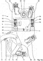
- the cooking device 2 is also designed as a domestic oven and comprises a housing 4, a cooking space 6 arranged in the housing 4 with a cooking space opening 8 and a door 10 assigned to the cooking space opening 8, the door 10 in a range of movement between one of the Fig. 14 and 16a to 16c corresponding closed position and one in the Fig. 13 shown and to the Figure 15a and 15b corresponding opening position of the door 10 is movable.
- the cooking space 6, namely the cooking space opening 8, is essentially tightly closed in the closed position of the door 10 and accessible in the open position of the door 10, with a first drive unit 12 and a second drive unit 14 on the housing 4 each for automatically moving the door 10 are arranged, and wherein the door 10 is movable by means of the first drive unit 12 in a first movement section of the movement range and by means of the second drive unit 14 in a second movement section of the movement range of the door 10.
- the door 10 is in its open position or in depending on the transfer of the door 10 whose closed position can be moved by means of the first drive unit 12 in the first movement section of the movement area and by means of the second drive unit 14 in the second movement section of the movement area of the door 10, which will be explained in more detail below.
- the door 10 is arranged to be pivotable about an axis of rotation 16 arranged on the housing 4, the first drive unit 12 and the second drive unit 14 being connected to the door 10 in a force-transmitting manner on the axis of rotation. See the Fig. 14 .
- the first movement segment of the door 10 extends from 0 ° to approximately 3 ° door opening, 0 ° door opening corresponding to the closed position of the door 10.
- the second movement section of the door 10 ranges from about 3 ° to about 85 ° door opening, with 85 ° door opening to that in the Fig. 13 illustrated opening position of the door 10 corresponds.
- the first movement section is positioned on the closing position side and the second movement section is positioned on the opening position side.
- the door 10 can be moved automatically by means of the first drive unit 12.
- the door 10 can be automatically moved by means of the second drive unit 14 in the first movement section and in the second movement section.
- the first drive unit 12 and the second drive unit 14 are each connected to the door 10 in a force-transmitting manner for the automatic movement of the door 10 by means of a common coupling device 50.
- the coupling device 50 comprises a lever 51 which is connected to the door 10 of the cooking appliance 2 in a force-transmitting manner in a manner known to the person skilled in the art. See the Fig. 14 , in which, however, only the mechanism of the door 10 connected to the coupling device 50 in a torque-transmitting manner is shown.
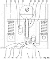
- the first drive unit 12 has a force introduction device 52, the force introduction device 52 between one in the Figures 16a to 16c engagement position shown, in which the force introduction device 52 is in force-transmitting engagement with the coupling device 50, and one in the Figure 15a and 15b non-engagement position shown, in which the force introduction device 52 is not in force-transmitting engagement with the coupling device 50 and can be transferred back and forth.
- the view in the Figure 15b differs from the view in the Figure 15a only by the fact that in the Figure 15b the slide 58 is not shown in order to be able to see the force application device 52. Same goes for that Figure 16a and 16b .
- the carriage 58 is partially shown.
- the first drive unit 12 in the present second embodiment a motor 54, for example an electric motor, an eccentric 56 connected to the motor 54 to transmit torque, and a slide 58, the slide 58 being resiliently mounted on the housing 4 by means of two return springs 60 in such a way that the force introduction device 52 mounted on the slide 58 by means of of the return springs 60 can automatically be transferred from their engaged position to their non-engaged position, and the motor 54, the eccentric 56 and the slide 58 are designed and arranged in relation to one another in such a way that the force introduction device 52 mounted on the slide 58 by means of the motor 54, the eccentric 56 and the carriage 58 can be automatically transferred from its disengaged position into its engaged position.
- a motor 54 for example an electric motor
- an eccentric 56 connected to the motor 54 to transmit torque
- a slide 58 being resiliently mounted on the housing 4 by means of two return springs 60 in such a way that the force introduction device 52 mounted on the slide 58 by means of of the return springs 60 can automatically be transferred from their engaged position to
- the slide 58 is guided on the housing 4 by means of corresponding guide means 5, 59, the guide means of the housing 4 being designed as two guide bolts 5 and the corresponding guide means of the slide 58 as two elongated holes 59 arranged parallel to one another. See for example the Figure 15a .
- the force introduction device 52 is resiliently mounted on the slide 58 by means of a force introduction spring 62, namely in such a way that a range of movement of the force introduction device 52 relative to the slide 58 is limited by means of mutually corresponding limiting means 64, 66 of the force introduction device 52 and the slide 58.
- the mutually corresponding limiting means 64, 66 are designed as an elongated hole 64 in the slide 58 and a bolt 66 of the force introduction device 52 corresponding to the elongated hole 64. See for example the Figure 15a and 15b in the synopsis.
- An impeller 68 is arranged on the bolt 66, which is rotatably arranged on the rest of the force introduction device 52, so that the force introduction device 52 can roll with little friction in its position of engagement on the coupling device 50. See for example the Figures 16a to 16c in the synopsis. In the Figure 16c the impeller 68 acts more like a polygon in cross section; in practice, however, the impeller 68 has a circular running surface.
- the coupling device 50 has a coupling link 70
- the force introduction device 52 of the first drive unit 12 in its engagement position by means of the Coupling link 70 is in engagement with the coupling device 50, namely in such a way that the coupling link 70 has a coupling link incline 72 for diverting a force introduced into the coupling device 50 by means of the force introduction device 52. See the Figure 16b and 16c .
- the coupling device 50 also has a control link 74, the control link 74 for actuating a total of three with a controller 7 of the cooking appliance 2 signal-transmitting connected switches 76, 78, 80, namely that the plurality of switches 76, 78, 80 can be operated by means of the control link 74 in such a way that the individual switches 76, 78, 80 are used to open the door 10, the closed position of the Door 10 and an intermediate position of the door 10 can be detected, the first movement section being formed between the intermediate position and the closed position of the door 10 and the second movement section being formed between the intermediate position and the open position of the door 10.
- the switch 76 is used to detect the open position of the door 10, the switch 78 to detect the intermediate position of the door 10 and the switch 80 to detect the closed position of the door 10.
- the force introduction device 52 of the first drive unit 12 is in the present embodiment depending on the detection of the intermediate position during the transfer of the door 10 in its closed position from its non-engagement position into its engagement position, which is explained in more detail below.
- the switches 82 and 84 both serve to detect a rotational position of the eccentric 56, the switches 82, 84 and the eccentric 56 being designed and arranged in relation to one another in such a way that both switches 82, 84 can be actuated simultaneously by the eccentric 56 when the eccentric is in motion 56 in one in the Figures 16a to 16c position shown, which corresponds to the engagement position of the force introduction device 52 is located.
- neither of the two switches 82, 84 can be actuated by means of the eccentric 56 when the eccentric 56 is in one of the Figure 15a , 15b position shown, which corresponds to the non-engagement position of the force introduction device 52 is located.
- the second drive unit 14 is continuously connected to the coupling device 50 in a force-transmitting manner.
- a motor 86 for example an electric motor, of the second drive unit 14 is connected to the coupling link 70 in a torque-transmitting manner. See for example the Fig. 14 and 15a in the synopsis.
- the door 10 of the cooking appliance 2 is initially in their to the Figures 16a to 16c corresponding closed position, so that the cooking space opening 8 and thus the cooking space 6 is closed.
- the door 10 is held by means of the first drive unit 12 with the force introduction device 52 and the coupling link 70 of the coupling device 50, so that the door 10 is effectively secured against undesired automatic opening.
- the force application device 52 In the closed position of the door 10, the force application device 52 is in its engagement position explained in more detail above. Both switches 82, 84 are actuated by means of the eccentric 56 in the manner explained above. The same applies to the switch 80. Corresponding electrical signals are present in the controller 7 of the cooking appliance 2, in the following manner known to the person skilled in the art, for example for controlling the motors 54, 86 of the first and second drive units 12, 14 and for performing Cooking functions.
- the opening position shown actuates a user (not shown) of the cooking appliance 2 in the present exemplary embodiment a into the Figures 13 to 16c
- the user presses an operating element designed as a push button.
- other operating elements are also conceivable.
- the transfer of the door 10 from its closed position to its open position can also be initiated automatically. For example, in that a program sequence of an automatic program stored in the controller 7 of the cooking appliance 2 provides for such an automatic transfer of the door 10.
- the force application device 52 is first removed from its position of engagement according to FIG Figures 16a to 16c in their non-engagement position according to Figure 15a and 15b convicted.
- the motor 54 of the first drive unit 12 is controlled accordingly by means of the controller 7, so that the motor 54 moves the eccentric 56 from its to the Figures 16a to 16c corresponding rotational position in its to the Figure 15a and 15b transferred to the corresponding rotational position.
- the motor 54 of the first drive unit 12 is then switched off by means of the controller 7. Due to the spring force of the two return springs 60, the carriage 58 and thus the force introduction device 52 arranged on the carriage 58 is in the respective plane of the image Figures 15a to 16c moved up.
- the to the Figure 15a and 15b The corresponding rotational position of the eccentric 56 is detected in the manner explained above by means of the two switches 82, 84 and forwarded to the controller 7.
- the door 10 is now by means of the second drive unit 14 further from a position of the door 10 located between the closed position and the intermediate position, via its intermediate position in its in the Fig. 13 shown opening position transferred.
- the door 10 is balanced in such a way that very little force is required to move the door 10 from its closed position to its open position, that is, over the entire range of movement of the door 10 in the direction of the open position.
- the motor 86 of the second drive unit 14 can be designed to be weak and therefore inexpensive.
- the opening position of the door 10 can be detected by means of the switch 76. In order to transfer the door 10 from their in the Fig.
- the door 10 is first automatically moved by means of the second drive unit 14 from its open position, i.e. at approximately 85 ° door opening, to approximately 3 ° door opening.
- the door 10 is in its intermediate position, which is detected by the switch 78 and passed on to the controller 7.
- the controller 7 then switches off the motor 86 of the second drive unit 14 so that the door 10 is no longer moved with the second drive unit 14 in the direction of its closed position.
- the controller 7 controls the motor 54 in a manner known to the person skilled in the art in such a way that the motor 54 moves the eccentric 56 into the Figure 15a and 15b rotational position shown in its in the Figures 16a to 16c shown rotational position transferred.
- the motor 54 drives the eccentric 56 in the image plane of the Figure 15a turns left or right.
- the eccentric 56 presses the carriage 58 against the spring force of the two return springs 60 in the respective image plane of the Figures 15a to 16c downwards, so that the force introduction device 52 arranged on the slide 58 is transferred from its non-engagement position into its engagement position and comes into force-transmitting engagement with the coupling link 70.
- the force introduction device 52 presses against the coupling slot bevel 72 by means of the impeller 68, so that the force introduced into the coupling slot 70 by means of the force introduction device 52 is deflected in such a way that the door 10 essentially tightly closes the cooking chamber opening 8 of the cooking chamber 6 by means of the coupling device 50.
- the door 10 is thus moved by means of the first drive unit 12 from approximately 3 ° door opening to 0 ° door opening, that is to say in the first movement section when the door 10 is moved from its open position to its closed position.
- the first drive unit 12 presses the door 10 by means of the force introduction device 52, for example, against the above-mentioned sealing device, not shown, in such a way that the door 10 in its closed position rests tightly against the sealing device, not shown.
- the higher force required for this and applied by the first drive unit 12, namely the pressing force against the aforementioned sealing device is only required over the small first movement section. Due to the favorable arrangement of the first drive unit 12 in terms of power transmission, it is nevertheless possible to reduce the required power of the first drive unit 12 to a minimum.
- the door 10 Due to the resilient contact of the force introduction device 52 arranged on the slide 58 with the coupling device 50, namely the coupling link 70, in the engagement position of the force application device 52, the door 10, with the force application device 52 in the engagement position, can be moved manually from its closed position to its open position against a spring force of the force application spring 62, for example by the user of the cooking appliance 2 (not shown).
- the force introduction device 52 moves in its range of motion limited by the limiting means 64, 66 of the slide 58 and the force introduction device 52 relative to the slide 58.
- the invention is not limited to the present exemplary embodiments of the cooking appliance according to the invention and the method according to the invention.
- the invention can also be used advantageously in other cooking appliances such as steamers, microwave appliances or combination appliances with a plurality of different types of heating.
- the invention can also be used in the professional field, that is to say in commercial cooking appliances.
- the door can be moved by means of the first drive unit in a first movement section of the movement range and by means of the second drive unit in a second movement section of the movement range of the door, regardless of whether the door is in its open position or in the whose closed position is transferred.
- embodiments with other dependencies are also possible when moving the door from its open position to its closed position or vice versa and when moving the door from the open position or its closed position to an intermediate position positioned between the open position and the closed position. The same applies to a transfer from one intermediate layer of the door to another intermediate layer of the door that deviates therefrom.
- the cooking appliance according to the invention in accordance with the second exemplary embodiment can, analogously to the first exemplary embodiment, also have a so-called rapid cooling function.
- an automatic program for the rapid cooling function of the cooking chamber is stored in the control of the cooking appliance, the door being automatically transferred to an intermediate layer corresponding to this automatic program when the automatic program is executed.
- the door is moved from its closed position to the aforementioned intermediate position, for example, automatically by means of the second drive unit, the door being automatically held in this intermediate position.
- the door can also be automatically transferred to at least one intermediate layer for other cooking appliance functions.
Landscapes
- Engineering & Computer Science (AREA)
- Chemical & Material Sciences (AREA)
- Combustion & Propulsion (AREA)
- Mechanical Engineering (AREA)
- General Engineering & Computer Science (AREA)
- Electric Ovens (AREA)
Applications Claiming Priority (1)
| Application Number | Priority Date | Filing Date | Title |
|---|---|---|---|
| DE102019122513 | 2019-08-21 |
Publications (3)
| Publication Number | Publication Date |
|---|---|
| EP3783266A1 true EP3783266A1 (fr) | 2021-02-24 |
| EP3783266B1 EP3783266B1 (fr) | 2023-12-27 |
| EP3783266C0 EP3783266C0 (fr) | 2023-12-27 |
Family
ID=72050711
Family Applications (1)
| Application Number | Title | Priority Date | Filing Date |
|---|---|---|---|
| EP20190665.8A Active EP3783266B1 (fr) | 2019-08-21 | 2020-08-12 | Appareil de cuisson doté d'un compartiment de cuisson pouvant être fermé |
Country Status (2)
| Country | Link |
|---|---|
| EP (1) | EP3783266B1 (fr) |
| DE (1) | DE202020005561U1 (fr) |
Cited By (4)
| Publication number | Priority date | Publication date | Assignee | Title |
|---|---|---|---|---|
| EP3881749B1 (fr) * | 2020-03-20 | 2022-05-11 | Miele & Cie. KG | Appareil électroménager à circulation d'eau |
| DE102021205018A1 (de) | 2021-05-18 | 2022-11-24 | BSH Hausgeräte GmbH | Haushaltsgerät mit spezifischer automatischer Türöffnung, sowie Verfahren |
| EP4174271A1 (fr) * | 2021-10-27 | 2023-05-03 | Miele & Cie. KG | Appareil avec un espace de traitement pour la préparation d'un aliment ou pour le nettoyage d'un produit à nettoyer et son procédé de fonctionnement |
| DE102022132280B3 (de) | 2022-12-06 | 2024-03-21 | Miele & Cie. Kg | System mit einem Haushaltgerät und einem Möbel zur Aufnahme des Haushaltgeräts sowie Verfahren zum Betrieb eines Systems |
Families Citing this family (3)
| Publication number | Priority date | Publication date | Assignee | Title |
|---|---|---|---|---|
| DE102023132657A1 (de) * | 2023-11-23 | 2025-05-28 | Miele & Cie. Kg | Haushaltsgerät mit beweglichem Verschlusselement |
| DE102023134410B4 (de) * | 2023-11-23 | 2025-06-26 | Miele & Cie. Kg | Haushaltsgerät mit beweglichem Verschlusselement |
| EP4560201A1 (fr) | 2023-11-23 | 2025-05-28 | Miele & Cie. KG | Appareil ménager avec élément de fermeture mobile |
Citations (4)
| Publication number | Priority date | Publication date | Assignee | Title |
|---|---|---|---|---|
| DE102004061231B3 (de) * | 2004-12-20 | 2006-04-20 | Ellenberger & Poensgen Gmbh | Türverriegelung für einen Herd |
| EP2784257A1 (fr) * | 2013-03-29 | 2014-10-01 | Nuova Star S.p.A. | Système de mise en mouvement d'une porte d'appareil électroménager et appareil électroménager avec le système |
| DE102016107137A1 (de) * | 2016-04-18 | 2017-05-18 | Miele & Cie. Kg | Kücheneinbaugerät und Verfahren zum Betreiben |
| EP3572606A1 (fr) * | 2018-05-23 | 2019-11-27 | Miele & Cie. KG | Dispositif pour la préparation d'aliments et / ou de boissons ou pour le nettoyage d'un article à nettoyer |
-
2020
- 2020-08-12 DE DE202020005561.1U patent/DE202020005561U1/de active Active
- 2020-08-12 EP EP20190665.8A patent/EP3783266B1/fr active Active
Patent Citations (4)
| Publication number | Priority date | Publication date | Assignee | Title |
|---|---|---|---|---|
| DE102004061231B3 (de) * | 2004-12-20 | 2006-04-20 | Ellenberger & Poensgen Gmbh | Türverriegelung für einen Herd |
| EP2784257A1 (fr) * | 2013-03-29 | 2014-10-01 | Nuova Star S.p.A. | Système de mise en mouvement d'une porte d'appareil électroménager et appareil électroménager avec le système |
| DE102016107137A1 (de) * | 2016-04-18 | 2017-05-18 | Miele & Cie. Kg | Kücheneinbaugerät und Verfahren zum Betreiben |
| EP3572606A1 (fr) * | 2018-05-23 | 2019-11-27 | Miele & Cie. KG | Dispositif pour la préparation d'aliments et / ou de boissons ou pour le nettoyage d'un article à nettoyer |
Cited By (6)
| Publication number | Priority date | Publication date | Assignee | Title |
|---|---|---|---|---|
| EP3881749B1 (fr) * | 2020-03-20 | 2022-05-11 | Miele & Cie. KG | Appareil électroménager à circulation d'eau |
| DE102021205018A1 (de) | 2021-05-18 | 2022-11-24 | BSH Hausgeräte GmbH | Haushaltsgerät mit spezifischer automatischer Türöffnung, sowie Verfahren |
| EP4174271A1 (fr) * | 2021-10-27 | 2023-05-03 | Miele & Cie. KG | Appareil avec un espace de traitement pour la préparation d'un aliment ou pour le nettoyage d'un produit à nettoyer et son procédé de fonctionnement |
| BE1029884B1 (de) * | 2021-10-27 | 2023-05-31 | Miele & Cie | Gerät mit einem Behandlungsraum zur Zubereitung eines Lebensmittels oder zur Reinigung eines zu reinigenden Gutes und Verfahren zu dessen Betrieb |
| EP4382710A3 (fr) * | 2021-10-27 | 2024-08-07 | Miele & Cie. KG | Appareil avec un espace de traitement pour la préparation d'un aliment ou pour le nettoyage d'un produit à nettoyer et son procédé de fonctionnement |
| DE102022132280B3 (de) | 2022-12-06 | 2024-03-21 | Miele & Cie. Kg | System mit einem Haushaltgerät und einem Möbel zur Aufnahme des Haushaltgeräts sowie Verfahren zum Betrieb eines Systems |
Also Published As
| Publication number | Publication date |
|---|---|
| EP3783266B1 (fr) | 2023-12-27 |
| DE202020005561U1 (de) | 2021-08-30 |
| EP3783266C0 (fr) | 2023-12-27 |
Similar Documents
| Publication | Publication Date | Title |
|---|---|---|
| EP3783266B1 (fr) | Appareil de cuisson doté d'un compartiment de cuisson pouvant être fermé | |
| EP3336292B1 (fr) | Procédé d'actionnement d'une serrure de porte et serrure de porte | |
| EP2652401B1 (fr) | Unité vanne de gaz comportant un mécanisme d'actionnement pour une électrovanne | |
| DE102009002276A1 (de) | Hausgerätvorrichtung | |
| AT504333A4 (de) | Vorrichtung zum sperren eines schlosses | |
| WO2006066646A1 (fr) | Verrouillage de porte de cuisinière | |
| WO2012163330A1 (fr) | Dispositif d'actionnement | |
| EP1690272A1 (fr) | Circuit et dispositif de detection de diverses positions d'un element de porte | |
| EP0481503A1 (fr) | Verrouillage de porte pour appareil ménager | |
| EP3631301B1 (fr) | Dispositif de fermeture électromécanique pour portes d'appareils | |
| EP3754680B1 (fr) | Dispositif de commutation pour un appareil de cuisson doté d'un espace de cuisson pouvant être fermé par une porte et appareil de cuisson | |
| DE10312305B4 (de) | Türverriegelung für elektrische Geräte, insbesondere für Waschmaschinen | |
| DE102008055516A1 (de) | Modulartig aufgebaute Zentralverriegelungseinheit für ein Kfz | |
| EP4174271B1 (fr) | Appareil avec un espace de traitement pour la préparation d'un aliment ou pour le nettoyage d'un produit à nettoyer et son procédé de fonctionnement | |
| DE102008021979A1 (de) | Betätigungseinrichtung zur Entriegelung von Fahrzeugtüren | |
| DE102020121174A1 (de) | Gargerät mit einem mittels einer Tür verschließbaren Garraum und Verfahren zu dessen Betrieb | |
| EP3273164B1 (fr) | Appareil de cuisson comprenant un dispositif de verrouillage | |
| EP1418385B1 (fr) | Dispositif de verrouillage de porte pour four de cuisson | |
| DE102013212514A1 (de) | Türanlage | |
| DE102011085447A1 (de) | Haushaltsmaschine | |
| DE102020118728A1 (de) | Aufstellvorrichtung für ein Kraftfahrzeugtürelement | |
| EP3798393A1 (fr) | Dispositif de commande d'urgence destiné à l'ouverture manuelle d'une porte de véhicule | |
| EP1564498A1 (fr) | Circuit pour la commande d'un appareil de cuisson industrielle | |
| BE1031422B1 (de) | System mit einem Haushaltsgerät sowie Verfahren zum Betrieb eines Systems | |
| DE102019116335A1 (de) | Gargerät mit einem durch eine Tür verschließbaren Garraum |
Legal Events
| Date | Code | Title | Description |
|---|---|---|---|
| REG | Reference to a national code |
Ref country code: DE Ref legal event code: R138 Ref document number: 202020005561 Country of ref document: DE Free format text: GERMAN DOCUMENT NUMBER IS 502020006496 |
|
| PUAI | Public reference made under article 153(3) epc to a published international application that has entered the european phase |
Free format text: ORIGINAL CODE: 0009012 |
|
| STAA | Information on the status of an ep patent application or granted ep patent |
Free format text: STATUS: THE APPLICATION HAS BEEN PUBLISHED |
|
| AK | Designated contracting states |
Kind code of ref document: A1 Designated state(s): AL AT BE BG CH CY CZ DE DK EE ES FI FR GB GR HR HU IE IS IT LI LT LU LV MC MK MT NL NO PL PT RO RS SE SI SK SM TR |
|
| AX | Request for extension of the european patent |
Extension state: BA ME |
|
| STAA | Information on the status of an ep patent application or granted ep patent |
Free format text: STATUS: REQUEST FOR EXAMINATION WAS MADE |
|
| 17P | Request for examination filed |
Effective date: 20210824 |
|
| RBV | Designated contracting states (corrected) |
Designated state(s): AL AT BE BG CH CY CZ DE DK EE ES FI FR GB GR HR HU IE IS IT LI LT LU LV MC MK MT NL NO PL PT RO RS SE SI SK SM TR |
|
| GRAP | Despatch of communication of intention to grant a patent |
Free format text: ORIGINAL CODE: EPIDOSNIGR1 |
|
| STAA | Information on the status of an ep patent application or granted ep patent |
Free format text: STATUS: GRANT OF PATENT IS INTENDED |
|
| RIC1 | Information provided on ipc code assigned before grant |
Ipc: E05F 15/611 20150101ALI20230907BHEP Ipc: F24C 15/02 20060101AFI20230907BHEP |
|
| INTG | Intention to grant announced |
Effective date: 20231002 |
|
| GRAS | Grant fee paid |
Free format text: ORIGINAL CODE: EPIDOSNIGR3 |
|
| GRAA | (expected) grant |
Free format text: ORIGINAL CODE: 0009210 |
|
| STAA | Information on the status of an ep patent application or granted ep patent |
Free format text: STATUS: THE PATENT HAS BEEN GRANTED |
|
| REG | Reference to a national code |
Ref country code: DE Ref legal event code: R084 Ref document number: 502020006496 Country of ref document: DE |
|
| AK | Designated contracting states |
Kind code of ref document: B1 Designated state(s): AL AT BE BG CH CY CZ DE DK EE ES FI FR GB GR HR HU IE IS IT LI LT LU LV MC MK MT NL NO PL PT RO RS SE SI SK SM TR |
|
| REG | Reference to a national code |
Ref country code: GB Ref legal event code: FG4D Free format text: NOT ENGLISH |
|
| REG | Reference to a national code |
Ref country code: CH Ref legal event code: EP |
|
| REG | Reference to a national code |
Ref country code: DE Ref legal event code: R096 Ref document number: 502020006496 Country of ref document: DE |
|
| REG | Reference to a national code |
Ref country code: IE Ref legal event code: FG4D Free format text: LANGUAGE OF EP DOCUMENT: GERMAN |
|
| U01 | Request for unitary effect filed |
Effective date: 20231227 |
|
| U07 | Unitary effect registered |
Designated state(s): AT BE BG DE DK EE FI FR IT LT LU LV MT NL PT SE SI Effective date: 20240109 |
|
| U79 | Statement concerning licences of right filed [unitary effect] |
Effective date: 20240112 |
|
| PG25 | Lapsed in a contracting state [announced via postgrant information from national office to epo] |
Ref country code: GR Free format text: LAPSE BECAUSE OF FAILURE TO SUBMIT A TRANSLATION OF THE DESCRIPTION OR TO PAY THE FEE WITHIN THE PRESCRIBED TIME-LIMIT Effective date: 20240328 |
|
| PG25 | Lapsed in a contracting state [announced via postgrant information from national office to epo] |
Ref country code: ES Free format text: LAPSE BECAUSE OF FAILURE TO SUBMIT A TRANSLATION OF THE DESCRIPTION OR TO PAY THE FEE WITHIN THE PRESCRIBED TIME-LIMIT Effective date: 20231227 |
|
| PG25 | Lapsed in a contracting state [announced via postgrant information from national office to epo] |
Ref country code: GR Free format text: LAPSE BECAUSE OF FAILURE TO SUBMIT A TRANSLATION OF THE DESCRIPTION OR TO PAY THE FEE WITHIN THE PRESCRIBED TIME-LIMIT Effective date: 20240328 Ref country code: ES Free format text: LAPSE BECAUSE OF FAILURE TO SUBMIT A TRANSLATION OF THE DESCRIPTION OR TO PAY THE FEE WITHIN THE PRESCRIBED TIME-LIMIT Effective date: 20231227 |
|
| PG25 | Lapsed in a contracting state [announced via postgrant information from national office to epo] |
Ref country code: RS Free format text: LAPSE BECAUSE OF FAILURE TO SUBMIT A TRANSLATION OF THE DESCRIPTION OR TO PAY THE FEE WITHIN THE PRESCRIBED TIME-LIMIT Effective date: 20231227 Ref country code: NO Free format text: LAPSE BECAUSE OF FAILURE TO SUBMIT A TRANSLATION OF THE DESCRIPTION OR TO PAY THE FEE WITHIN THE PRESCRIBED TIME-LIMIT Effective date: 20240327 Ref country code: HR Free format text: LAPSE BECAUSE OF FAILURE TO SUBMIT A TRANSLATION OF THE DESCRIPTION OR TO PAY THE FEE WITHIN THE PRESCRIBED TIME-LIMIT Effective date: 20231227 |
|
| PG25 | Lapsed in a contracting state [announced via postgrant information from national office to epo] |
Ref country code: IS Free format text: LAPSE BECAUSE OF FAILURE TO SUBMIT A TRANSLATION OF THE DESCRIPTION OR TO PAY THE FEE WITHIN THE PRESCRIBED TIME-LIMIT Effective date: 20240427 |
|
| PG25 | Lapsed in a contracting state [announced via postgrant information from national office to epo] |
Ref country code: CZ Free format text: LAPSE BECAUSE OF FAILURE TO SUBMIT A TRANSLATION OF THE DESCRIPTION OR TO PAY THE FEE WITHIN THE PRESCRIBED TIME-LIMIT Effective date: 20231227 |
|
| PG25 | Lapsed in a contracting state [announced via postgrant information from national office to epo] |
Ref country code: SK Free format text: LAPSE BECAUSE OF FAILURE TO SUBMIT A TRANSLATION OF THE DESCRIPTION OR TO PAY THE FEE WITHIN THE PRESCRIBED TIME-LIMIT Effective date: 20231227 |
|
| PG25 | Lapsed in a contracting state [announced via postgrant information from national office to epo] |
Ref country code: SM Free format text: LAPSE BECAUSE OF FAILURE TO SUBMIT A TRANSLATION OF THE DESCRIPTION OR TO PAY THE FEE WITHIN THE PRESCRIBED TIME-LIMIT Effective date: 20231227 Ref country code: SK Free format text: LAPSE BECAUSE OF FAILURE TO SUBMIT A TRANSLATION OF THE DESCRIPTION OR TO PAY THE FEE WITHIN THE PRESCRIBED TIME-LIMIT Effective date: 20231227 Ref country code: RO Free format text: LAPSE BECAUSE OF FAILURE TO SUBMIT A TRANSLATION OF THE DESCRIPTION OR TO PAY THE FEE WITHIN THE PRESCRIBED TIME-LIMIT Effective date: 20231227 Ref country code: IS Free format text: LAPSE BECAUSE OF FAILURE TO SUBMIT A TRANSLATION OF THE DESCRIPTION OR TO PAY THE FEE WITHIN THE PRESCRIBED TIME-LIMIT Effective date: 20240427 Ref country code: CZ Free format text: LAPSE BECAUSE OF FAILURE TO SUBMIT A TRANSLATION OF THE DESCRIPTION OR TO PAY THE FEE WITHIN THE PRESCRIBED TIME-LIMIT Effective date: 20231227 |
|
| PG25 | Lapsed in a contracting state [announced via postgrant information from national office to epo] |
Ref country code: PL Free format text: LAPSE BECAUSE OF FAILURE TO SUBMIT A TRANSLATION OF THE DESCRIPTION OR TO PAY THE FEE WITHIN THE PRESCRIBED TIME-LIMIT Effective date: 20231227 |
|
| PG25 | Lapsed in a contracting state [announced via postgrant information from national office to epo] |
Ref country code: PL Free format text: LAPSE BECAUSE OF FAILURE TO SUBMIT A TRANSLATION OF THE DESCRIPTION OR TO PAY THE FEE WITHIN THE PRESCRIBED TIME-LIMIT Effective date: 20231227 |
|
| REG | Reference to a national code |
Ref country code: DE Ref legal event code: R097 Ref document number: 502020006496 Country of ref document: DE |
|
| U20 | Renewal fee for the european patent with unitary effect paid |
Year of fee payment: 5 Effective date: 20240902 |
|
| PLBE | No opposition filed within time limit |
Free format text: ORIGINAL CODE: 0009261 |
|
| STAA | Information on the status of an ep patent application or granted ep patent |
Free format text: STATUS: NO OPPOSITION FILED WITHIN TIME LIMIT |
|
| 26N | No opposition filed |
Effective date: 20240930 |
|
| REG | Reference to a national code |
Ref country code: CH Ref legal event code: PL |
|
| PG25 | Lapsed in a contracting state [announced via postgrant information from national office to epo] |
Ref country code: MC Free format text: LAPSE BECAUSE OF FAILURE TO SUBMIT A TRANSLATION OF THE DESCRIPTION OR TO PAY THE FEE WITHIN THE PRESCRIBED TIME-LIMIT Effective date: 20231227 Ref country code: CH Free format text: LAPSE BECAUSE OF NON-PAYMENT OF DUE FEES Effective date: 20240831 |
|
| PG25 | Lapsed in a contracting state [announced via postgrant information from national office to epo] |
Ref country code: IE Free format text: LAPSE BECAUSE OF NON-PAYMENT OF DUE FEES Effective date: 20240812 |
|
| U20 | Renewal fee for the european patent with unitary effect paid |
Year of fee payment: 6 Effective date: 20250901 |
|
| PGFP | Annual fee paid to national office [announced via postgrant information from national office to epo] |
Ref country code: GB Payment date: 20250826 Year of fee payment: 6 |
|
| PG25 | Lapsed in a contracting state [announced via postgrant information from national office to epo] |
Ref country code: CY Free format text: LAPSE BECAUSE OF FAILURE TO SUBMIT A TRANSLATION OF THE DESCRIPTION OR TO PAY THE FEE WITHIN THE PRESCRIBED TIME-LIMIT; INVALID AB INITIO Effective date: 20200812 |
|
| PG25 | Lapsed in a contracting state [announced via postgrant information from national office to epo] |
Ref country code: HU Free format text: LAPSE BECAUSE OF FAILURE TO SUBMIT A TRANSLATION OF THE DESCRIPTION OR TO PAY THE FEE WITHIN THE PRESCRIBED TIME-LIMIT; INVALID AB INITIO Effective date: 20200812 |