EP3811046B1 - Ensemble de mesure de charge, procédé de fabrication pour celui-ci et procédé de mesure de charge pouvant être réalisé avec celui-ci - Google Patents
Ensemble de mesure de charge, procédé de fabrication pour celui-ci et procédé de mesure de charge pouvant être réalisé avec celui-ci Download PDFInfo
- Publication number
- EP3811046B1 EP3811046B1 EP19732617.6A EP19732617A EP3811046B1 EP 3811046 B1 EP3811046 B1 EP 3811046B1 EP 19732617 A EP19732617 A EP 19732617A EP 3811046 B1 EP3811046 B1 EP 3811046B1
- Authority
- EP
- European Patent Office
- Prior art keywords
- magnetic field
- test object
- load measuring
- measuring
- load
- Prior art date
- Legal status (The legal status is an assumption and is not a legal conclusion. Google has not performed a legal analysis and makes no representation as to the accuracy of the status listed.)
- Active
Links
Images



Classifications
-
- G—PHYSICS
- G01—MEASURING; TESTING
- G01L—MEASURING FORCE, STRESS, TORQUE, WORK, MECHANICAL POWER, MECHANICAL EFFICIENCY, OR FLUID PRESSURE
- G01L3/00—Measuring torque, work, mechanical power, or mechanical efficiency, in general
- G01L3/02—Rotary-transmission dynamometers
- G01L3/04—Rotary-transmission dynamometers wherein the torque-transmitting element comprises a torsionally-flexible shaft
- G01L3/10—Rotary-transmission dynamometers wherein the torque-transmitting element comprises a torsionally-flexible shaft involving electric or magnetic means for indicating
- G01L3/101—Rotary-transmission dynamometers wherein the torque-transmitting element comprises a torsionally-flexible shaft involving electric or magnetic means for indicating involving magnetic or electromagnetic means
- G01L3/102—Rotary-transmission dynamometers wherein the torque-transmitting element comprises a torsionally-flexible shaft involving electric or magnetic means for indicating involving magnetic or electromagnetic means involving magnetostrictive means
- G01L3/103—Details about the magnetic material used
-
- G—PHYSICS
- G01—MEASURING; TESTING
- G01L—MEASURING FORCE, STRESS, TORQUE, WORK, MECHANICAL POWER, MECHANICAL EFFICIENCY, OR FLUID PRESSURE
- G01L9/00—Measuring steady of quasi-steady pressure of fluid or fluent solid material by electric or magnetic pressure-sensitive elements; Transmitting or indicating the displacement of mechanical pressure-sensitive elements, used to measure the steady or quasi-steady pressure of a fluid or fluent solid material, by electric or magnetic means
- G01L9/16—Measuring steady of quasi-steady pressure of fluid or fluent solid material by electric or magnetic pressure-sensitive elements; Transmitting or indicating the displacement of mechanical pressure-sensitive elements, used to measure the steady or quasi-steady pressure of a fluid or fluent solid material, by electric or magnetic means by making use of variations in the magnetic properties of material resulting from the application of stress
Definitions
- the invention relates to a load measuring arrangement comprising a test object and a load measuring device for measuring a load on the test object, wherein the load measuring device has a magnetic field generating device for generating a magnetic field on a measuring area of the test object and a first and a second magnetic field detecting device for detecting a magnetic field parameter that changes due to the load.
- the invention further relates to a manufacturing method for such a load measuring arrangement and a load measuring method that can be carried out therewith.
- the invention relates in particular to a method and an arrangement for measuring a mechanical load on a test object.
- Loads are understood to mean forces, torques or mechanical stresses on the test object.
- Some embodiments of the invention relate in particular to a torque measuring arrangement with a torque transducer for a torque sensor for measuring a torque on a test object in the form of a shaft by detecting magnetic field changes.
- embodiments of the invention relate to a measuring method for measuring a torque by detecting magnetic field changes.
- a type of torque sensor as described in D4 ( EN 30 31 997 A1 ) has proven to be particularly effective for measuring torques in shafts and other measuring points.
- Magnetic measuring methods can be used to determine the physical quantities torque, force and position on ferromagnetic objects.
- Magnetoelastic (or inverse magnetostrictive) sensors or eddy current or eddy current sensors are usually used.
- the ferromagnetic materials used change their permeability under the influence of tensile or compressive stresses (also known as the Villari effect).
- the state of the object's magnetization is often unknown or is permanently influenced by the processing and handling of the objects, so that broad industrial use is often difficult.
- generator and detector coils are used, namely two first magnetic field detection coils A1, A2 and two second magnetic field detection coils B1, B2 and a central generator coil Lg in a cross arrangement (X arrangement).
- the difference between the coil pair AB (A1+A2) - (B1+B2) is determined in an analog signal processing scheme.
- the D8 US 2009/0249893 A1 discloses a measuring device in which a layer of a magnetoelastic alloy is arranged on a load-bearing element.
- the grain size of the layer is between 100 nm and 10,000 nm.
- D8 discloses a load measuring arrangement comprising a test object and a load measuring device for measuring a load on the test object, wherein the load measuring device has a magnetic field generating device for generating a magnetic field on a measuring region (11) of the test object (14) and a magnetic field detecting device for detecting a magnetic field parameter that changes due to the load, wherein the measuring region has a layer of a ferromagnetic amorphous or nanocrystalline metal with a maximum grain size of less than 1 ⁇ m, wherein the test object contains a body that is formed from the non-ferromagnetic material steel, and at least on the measuring region has a coating of the ferromagnetic amorphous or nanocrystalline metal in the form of a galvanic Fe-
- the D9 DE 3604088 A1 describes a pressure sensor with a pressure body that carries a structured amorphous magnetostrictive metal layer, as well as a sensor part that has a measuring and reference circuit.
- the magnetoelastic coupling in the metal layer causes a change in the magnetic permeability, which causes a change in inductance via the measuring circuit and is used to generate a voltage signal analogous to the pressure in comparison to the reference circuit.
- the invention has for its object to design a load measuring arrangement of the type specified in the preamble of claim 1 in such a way that it has a lower hysteresis effect and thus fewer measurement errors.
- the invention provides a load measuring arrangement according to claim 1.
- a manufacturing method for producing such a load measuring arrangement and a load measuring method are the subject of the further independent claims.
- the invention provides a load measuring arrangement comprising a test object and a load measuring device for measuring a load on the test object, wherein the load measuring device has a magnetic field generating device for actively generating a magnetic field on a measuring region of the test object and a first and a second magnetic field detecting device for detecting a magnetic field parameter changing due to the load, wherein the measuring region has a layer of a ferromagnetic amorphous or nanocrystalline metal with a maximum grain size of less than 1 ⁇ m.
- the test object contains a body made of a non-ferromagnetic material which has a coating made of the ferromagnetic amorphous or nanocrystalline metal at least in the measuring area.
- the layer of amorphous or nanocrystalline metal makes it particularly advantageous to measure loads such as torque or force using the Villari effect (inverse magnetostrictive effect) in test objects that are mainly made of non-ferromagnetic materials.
- loads such as torque or force using the Villari effect (inverse magnetostrictive effect) in test objects that are mainly made of non-ferromagnetic materials.
- torque or force can be measured non-contact on shafts, struts or other components that are made of stainless steel, aluminum, plastics or fiber composite materials.
- Metallic glasses - also called amorphous metals - are metal or metal and non-metal alloys that have an amorphous structure rather than a crystalline structure at the atomic level and still show metallic conductivity. Metals that have only very small crystals in the nano range, smaller than 1 ⁇ m, at the atomic level show similar or equally good behavior. Such metals with nanocrystals with a maximum grain size of smaller than 1 ⁇ m (e.g. diameter) are referred to here as nanocrystalline metals. Nanocrystalline materials are particularly preferred. This includes, for example, chemically deposited nickel (with glass formers such as phosphorus). Chemical nickel with the phosphorus content according to the invention is not yet completely amorphous.
- Magnetic amorphous or nanocrystalline metals are used in the invention.
- amorphous or nanocrystalline alloys of at least one glass former from the group containing boron, silicon and phosphorus and at least one metal from the group containing nickel, chromium, iron and cobalt are also used.
- Many of these metallic glasses are magnetic, usually (especially when cobalt is not dominant) soft magnetic, i.e. with low coercive field strength.
- the amorphous or nanocrystalline metal further comprises a metal alloy comprising at least one metal from the group iron, nickel, cobalt and molybdenum.
- the amorphous or nanocrystalline metal further comprises a metal alloy comprising at least one glass former.
- the glass former is preferably a glass former from the group silicon, boron and phosphorus.
- the proportion of glass former is 2 to 30 atom percent.
- the invention provides that the amorphous or nanocrystalline metal has or is chemical nickel with a phosphorus content of 2 to 11% by weight, preferably 5 to 9%.
- the amorphous or nanocrystalline metal further comprises a metal alloy containing 65 to 95 atomic percent of one or more metals from the group iron, cobalt and nickel and 5 to 35 atomic percent of one or more glass formers from the group silicon, boron and phosphorus.
- the body is formed from or with a non-ferromagnetic material from the group comprising stainless steel, aluminum, plastic, fiber-reinforced plastic, GRP, CFRP.
- the layer of ferromagnetic amorphous or nanocrystalline metal is only partially provided on the test object. It is particularly preferred that the layer is formed over the entire surface, without interruptions in the surface, i.e. without patterning in the surface, so that a uniform magnetic field spread over the surface is achieved.
- the coating makes it possible to measure stresses on non-ferromagnetic test objects in particular.
- test object is rotatable about a rotation axis relative to the load measuring device.
- test object can be a shaft rotating about an axis of rotation on which a torque is to be measured.
- the magnetic field generating device is designed to actively generate a radial magnetic field in the measuring area of the test object.
- the magnetic field generating device can be easily integrated into a measuring head that points radially to the test object.
- a first measuring region of the test object has a layer of the amorphous or nanocrystalline metal that is uniformly continuous in the circumferential direction with respect to the axis of rotation.
- the layer of amorphous or nanocrystalline metal can be provided on a shaft around the entire circumference, for example.
- a second measuring region axially displaced relative to the first measuring region in the direction of the axis of rotation has a layer of the amorphous or nanocrystalline metal which is provided only on a part of the circumference and/or has a magnetic field-influencing material parameter which changes depending on the circumferential position.
- an angle dependence of a the magnetic field generating device or another magnetic field generating device generates a magnetic field induced in the test object during relative rotation of the test object and the load measuring device.
- This angle dependency can be measured with one of the magnetic field detection devices or with an additionally provided coil or the like. In this way, a combination sensor can be created that measures a load and a speed or, if necessary, also an angle of rotation.
- the layer in the second measuring area can also be applied with a material parameter that influences the magnetic field and changes depending on the circumference.
- the material parameter can be, for example, a layer thickness or width or a material composition.
- the strain measuring device has a sensor head.
- the sensor head comprises a magnetic field generating coil, a first magnetic field measuring coil and a second magnetic field measuring coil in a V-arrangement.
- the sensor head comprises a magnetic field generating coil and a first to fourth magnetic field measuring coil in an X arrangement.
- Step a) includes: Deposition of electroless nickel with a phosphorus content of 2 to 12 wt.%, preferably 5 to 9 wt.%.
- Chemical nickel is a chemical coating. It can be deposited as wear or corrosion protection. This creates chemical nickel layers.
- the difference to electroplated nickel is, among other things, that no external electrical current, such as from a rectifier, is used for the deposition; instead, the electrons required to deposit (reduce) the nickel ions are generated in the bath itself by means of a chemical oxidation reaction.
- Deposition is preferably carried out at temperatures below 200°, more particularly less than 150°, and most particularly in the range of 90°. This means that rapid cooling is not necessary.
- step a) further comprises: a3) partially coating a peripheral region of the test object relative to an axis of the test object.
- step a) further comprises: a5) Generating a circumferential position signature at a circumferential location on the test object by partially applying the coating, by structuring the coating or by generating the coating with a material parameter that influences the magnetic field and is changed at this circumferential location.
- step a) further comprises: a6) Creating a continuous layer without interruptions.
- step a) further comprises: a7) Deposition of a metallic glass.
- step a) further comprises: a8) depositing an alloy comprising at least one metal selected from the group consisting of iron, nickel, cobalt and molybdenum.
- step a) further comprises: a9) depositing an alloy comprising at least one glass former.
- step a) further comprises: a10) depositing an alloy containing at least one glass former selected from the group consisting of silicon, boron and phosphorus.
- step a) further comprises: a11) Depositing an alloy containing 2 to 30 atomic percent of at least one glass former, in particular from the group consisting of silicon, boron and phosphorus.
- step a) further comprises: a12) Depositing an alloy containing 65 to 95 atomic percent of one or more metals from the group iron, cobalt and nickel and 5 to 35 atomic percent of one or more glass formers from the group silicon, boron and Contains phosphorus.
- other alloying additives can be included.
- Preferred embodiments of the invention relate to the idea of a Metglas coating (Metglas - metallic glass, i.e. amorphous metal) or a nanocrystalline metal coating for torque measurement and combination of sensors.
- Metglas coating Metal - metallic glass, i.e. amorphous metal
- nanocrystalline metal coating for torque measurement and combination of sensors.
- Non-ferromagnetic materials such as stainless steel, aluminum, plastic, and GRP compounds cannot be used.
- Preferred embodiments of the invention provide for the deposition of a layer on these substrates which has ferromagnetic properties.
- Metglas deposits and nanocrystalline metal deposits made of nickel exhibit such properties.
- weight reductions of the workpieces used can be permitted, or the test objects, e.g. designed as shafts, can be manufactured using injection molding processes.
- shafts or other test objects such as struts, gear elements, chainrings, etc. can be manufactured from other materials more cheaply and other dimensions can be realized.
- Metglas or nanocrystalline metal only partially to the test object, e.g. a shaft.
- a torque measurement can be carried out at one point using Metglas/nanocrystalline metal and a signature for an angle measurement can be applied at another point on the shaft using Metglas/nanocrystalline metal.
- this structuring of the shaft can either be done by subsequently removing material, or the Metglas/nanocrystalline metal can only be applied at dedicated points, for example.
- a preferred embodiment of the invention provides a Metglas/nanocrystalline metal coated shaft for torque measurements.
- any non-ferromagnetic material that can be coated with a well-adhering ferromagnetic met-glass/nanocrystal metal coating can serve as the test object material, e.g. shaft material.
- the coating is not destroyed by the application of force.
- the layer of amorphous or nanocrystalline metal can be applied externally, for example. Since such layers are harder and more corrosion-resistant than other metals, they are well suited as an external material.
- the layer can also be a layer under one or more cover layers.
- the layer is applied by deposition.
- the deposited material should be ferromagnetic and amorphous or nanocrystalline (e.g. metallic glass).
- the corresponding coatings are obtained by rapid deposition of electroless nickel with a phosphorus content of 5-9 % by weight, which only undergoes a very moderate heat treatment - such a coating is not yet completely amorphous, but can still have crystals with grain sizes below 1 ⁇ m.
- a homogeneous closed layer is provided.
- the good mechanical connection to the base substrate is advantageous.
- Typical layer thicknesses of > 10 ⁇ m, 30 ⁇ m and 40 ⁇ m have proven to be well suited in tests.
- the load measuring arrangement is a combination of a rotating test object, such as a shaft, a wheel, a gear, a chainring or the like, and a torque sensor for measuring a torque on the test object.
- a rotating test object such as a shaft, a wheel, a gear, a chainring or the like
- a torque sensor for measuring a torque on the test object.
- This embodiment can be used, for example, on an e-bike, whereby the torque can be measured on the crank or an element provided with it.
- CFRP with a layer of metglass or nanocrystalline metal can be used, for example.
- the stress measuring arrangement is a pressure sensor with at least one membrane to be subjected to a pressure to be measured as a test object and a magnetoelastic stress detection device as a stress measuring device for magnetoelastically detecting a mechanical stress caused by the pressure application.
- the membrane can be made of stainless steel, for example, and coated with metglass or nanocrystalline metal. Stainless steel has excellent properties for use as a membrane, in particular corrosion resistance and elastic behavior.
- the load measuring device 12 is used to measure mechanical loads, such as in particular torques, forces or stresses, in an at least partially magnetizable test object 14, preferably rotatable about an axis of rotation, such as a shaft, a gear part, a wheel hub, a chainring or the like.
- the test object 14 can also be stationary, e.g. a carrier or a strut in a support structure on which loads or forces are to be measured.
- the test object 14 is provided at least in one measuring area 11 with a layer 13 made of a ferromagnetic metallic glass or of ferromagnetic nanocrystalline metal, which will be explained in more detail below.
- the test object 14 and the load measuring device 12 together form a load measuring arrangement 16.
- the load measuring device 12 has a magnetic field generating device 18 and several magnetic field detecting devices 20, 22.
- the load measuring device 12 has a rotation angle detection device 40 for detecting a rotation angle of the test object 14 and an evaluation device 42 for reducing the influence of rotation angle-dependent effects on the load measurement.
- the evaluation device 42 is connected to the rotation angle detection device 40 and to the magnetic field detection devices 20, 22.
- the evaluation device 42 is in particular set up to reduce the RSN using the rotation angle information.
- the magnetic field generating device 18 has a generator coil Lg and a driver circuit (not shown in detail) for driving the generator coil Lg.
- the magnetic field detection devices 20, 22 have magnetic field sensors 26 in the form of detector coils A1, A2, B1, B2 or solid-state magnetic field sensors 27 and an evaluation device 42 for evaluating the signals of the magnetic field sensors 26.
- FIG.1 The embodiment of the sensor head 10 shown with a view to the front side directed towards the test object 14 is shown in Fig.3 shown from the side.
- This embodiment has two first magnetic field sensors 26-1 designed as first detector coils A1, A2 and two second magnetic field sensors 26-2 designed as second detector coils B1, B2.
- the detector coils A1, A2, B1, B2 are provided in a cross-shaped arrangement or X-arrangement 28 on a common flux concentrator 30 made of ferromagnetic material.
- the generator coil Lg is provided in the middle - here also on a corresponding projection of the flux concentrator 30 - with the first detector coils A1 and A2 facing each other and the second detector coils B1 and B2 facing each other.
- Fig.2 shows a further embodiment of the sensor head 10 with a V-arrangement 32, where only a first magnetic field sensor 26-1 - eg the first detector coil A1 - and only a second magnetic field sensor 26-1 are arranged at an angle to each other with the generator coil Lg at the tip of the angular shape.
- solid-state magnetic field sensors 27 can also be provided as first and second magnetic field sensors 26-1, 26-2.
- Fig.5 shows an embodiment of the sensor head 10, in which the coils - detector coils A1, A2, B1, B2 and generator coil Lg - are provided as planar coils 34 in a printed circuit board element 36 - e.g. designed as PCB boards.
- the strain measuring device 12 implements a new signal processing concept for tapping and processing the signals of the magnetic field sensors 26-1, 26-2.
- the test object 14 is provided with a layer 13 of ferromagnetic amorphous or nanocrystalline metal.
- Amorphous metals are also called metallic glasses. Glasses are solid materials without a crystal structure. This means that the atoms do not form a lattice, but are arranged randomly at first glance: there is no long-range order, but at most a short-range order; this structure is referred to as amorphous. Nanocrystalline metal is a metal that still has very small crystals with maximum grain sizes of less than 1 ⁇ m. Tests have shown that nanocrystalline metals have comparable magnetic properties to corresponding amorphous metals.
- amorphous or nanocrystalline metals are created by completely or largely preventing natural crystallization. This can be done, for example, by rapidly cooling ("quenching") the melt, so that the atoms are deprived of their mobility before they can assume the crystal arrangement.
- Metallic glasses and nanocrystalline metals in the form of alloys made of at least two metals are known, which can be amorphized. More common are amorphous or nanocrystalline alloys made of just one metal - e.g. Fe - and a so-called glass former - e.g. boron or phosphorus, for example in the composition Fe4B.
- the layer of amorphous or nanocrystalline metal is formed as a thin strip of a melt that is poured onto a cooled, rotating body of the test object 14 and cools suddenly.
- a thin amorphous or nanocrystalline layer 13 is obtained by chemical vapor deposition or sputter deposition. This also makes it easy to selectively coat only a portion of the test object 14.
- amorphous or nanocrystalline atomic arrangement which is very unusual for metals, results in a unique combination of physical properties: amorphous and nanocrystalline metals are generally harder, more corrosion-resistant and stronger than ordinary metals.
- Metallic glasses show, among other things, the typical metallic light reflection and are indistinguishable from ordinary metals for the layman.
- the surface can be polished particularly smoothly and does not scratch easily due to its great hardness, so a particularly beautiful and long-lasting shine can be achieved.
- Metallic glasses are harder than their crystalline counterparts and have a high level of strength. Small deformations ( ⁇ 1%) are purely elastic. This means that the absorbed energy is not lost as deformation energy, but is fully released when the material springs back.
- the corrosion resistance is generally higher than that of metals with a comparable chemical composition. This is because corrosion usually attacks grain boundaries between the individual crystallites of a metal, which do not exist in amorphous materials.
- weiss domains In magnetism, Weiss domains (also Weiss domains, after the French physicist Pierre-Ernest Weiss) are microscopically small magnetized domains in the crystals of a ferromagnetic material. The size of these domains ranges from about 10 to 1000 ⁇ m in linear extension. The direction of magnetization is based on the crystal lattice of the material. In materials whose grain size is this order of magnitude or even smaller, all crystallites are single-domain particles, i.e. they are not further divided into domains.
- Amorphous and nanocrystalline metals are homogeneous and their magnetic properties are the same in all directions. Magnetization is therefore much easier. This is particularly noticeable when the direction of the magnetic field changes again. In a metal with a lattice structure, it is often more energy-intensive to restore the original state; residual magnetization (remanence) remains. Amorphous and nanocrystalline metals therefore have a much lower hysteresis effect.
- the hysteresis effect is particularly problematic in torque measurements with active magnetization and can lead to measurement errors.
- great efforts have therefore been made to reduce the hysteresis effect.
- the designs presented here use the method of providing the measuring area of the test object with a layer of amorphous or nanocrystalline metals.
- Nanocrystalline materials are produced by deposition of chemical nickel.
- the manufacturing process of amorphous and crystalline metallic glass ribbons results in some outstanding properties.
- the individual elementary magnets in the material are partially insulated from one another by the non-conductive glass-forming elements, so that the specific resistance of the material, at around 120 to 150 ⁇ cm, is about three times higher than that of electrical steel. They are also very small; in crystalline metallic glass ribbons they are around 10 nm. This means that the eddy current losses, even at higher frequencies, are lower than in other crystalline alloys.
- magnetic amorphous or nanocrystalline metals are used for the layer 13. This allows a Coating with one of the best commercially available soft magnetic materials. This produces a layer with excellent ferromagnetic properties, so that the load measurement can be carried out very accurately even with low field strengths.
- Amorphous or nanocrystalline alloys made from the glass formers boron, silicon and phosphorus and the metals iron, cobalt and/or nickel are magnetic, usually (i.e. when cobalt is not dominant) soft magnetic, i.e. with low coercive field strength, and at the same time have a high electrical resistance.
- the conductivity is usually metallic, but of the same order of magnitude as that of molten metals just above the melting point. This leads to low electrical eddy current losses.
- Conventional metals typically contract suddenly when solidifying. Since solidification as a glass is not a first-order phase transition, this jump in volume does not occur here. If the melt of a metallic glass fills a mold, it retains this mold when it solidifies.
- the layer 13 is made of amorphous or nanocrystalline metal.
- the layer 13 is amorphous or nanocrystalline with a grain size of ⁇ 1 ⁇ m up to amorphous alloys.
- alloys for forming ferromagnetic metallic glasses e.g. in the composition (Fe, Ni, Co) 70-85 (Si, B)15-30, are used for production.
- the composition is to be read as a chemical formula; i.e. 70-85 atomic percent of any mixture of iron, cobalt and nickel with 15-30 atomic percent of any mixture of boron and silicon.
- Such an alloy becomes amorphous or nanocrystalline by very rapid quenching; alternatively, the layer is first produced amorphous and then heated to form nanocrystals.
- Another embodiment uses (Fe0.68Dy0.07B0.2Si0.05)96Nb4, where the iron content is ⁇ 70 atomic percent.
- the material of layer 13 preferably contains glass formers, in particular Si, B and/or P. Accordingly, nanocrystalline, ferromagnetic materials used in embodiments also preferably contain glass formers.
- a concrete example would be Fe91Zr7B3, which has a typical grain size of 17 nm.
- the alloy preferably contains atomic proportions of Si, B and P in the range of 2...30 atomic percent.
- the aforementioned alloys are applied to the measuring area by methods known for producing metallic glasses.
- layers 13 of metallic glass can be applied in different ways to a body 48 of the test object 14, wherein the body 48 can be formed from very different, in particular non-ferromagnetic materials.
- Fig.6 A currently preferred embodiment of a method step for producing the test object 14 provided with the layer 13 is explained.
- a bath 66 is provided for selectively coating a body 48 of the test object 14.
- the bath 66 is designed in such a way that only the partial area to be coated, e.g. the measuring area 11, is wetted by the bath 66.
- the bath 66 is designed for depositing chemical nickel. Chemical nickel, in particular with a phosphorus content of 5 to 9 wt.%, is deposited on the body 48 in such a way that amorphous metal is formed as a layer 13.
- Such selective coating with chemical nickel is offered by various service providers on the market.
- the body 48 of the test object is completely immersed in a correspondingly larger bath 66.
- the entire surface of the body 48 is provided with the layer 13 of amorphous chemical nickel.
- test object 14 can be, for example, a shaft 46 rotatable about a rotation axis 44.
- a first measuring region 11a is provided with a first layer 13a made of amorphous or nanocrystalline metal on the test object 14, which can be rotated about the rotation axis 44 relative to the load measuring device 12.
- the first layer 13a extends circumferentially over the entire circumferential region around the test object 14 and is provided uniformly around the entire circumferential region.
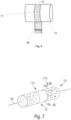
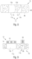
- a second layer 13b made of amorphous or nanocrystalline metal is provided on a second measuring region 11b which is axially offset from the first measuring region 11a with respect to the axis of rotation 44 and which is only partially provided on a peripheral region, as shown in Fig.7 or is provided such that a magnetic field influencing parameter of the layer 13b changes depending on the circumferential position.
- the width of the layer changes depending on the circumferential position, as shown in Fig.8 is shown.
- the test object 14 has a body 48 on which the layer 13, 13a, 13b is applied.
- the body 48 is made of non-ferromagnetic material, such as aluminum, stainless steel or, as shown, a fiber composite material, e.g. GRP or CFRP.
- Fig.9 the load measuring arrangement 16 is connected to the test object 14 according to one of the Fig.7 or 8th shown.
- the load measuring device 12 can be one of the previously determined Fig. 1 to 5 explained sensor heads 10 and at least one further coil 50.
- several further coils 50 are provided around the test object 14.
- a current is passed through the further coil 50 and the impedance of the further or each further coil 50 is recorded. If a partially provided second layer 13b of the Fig.7 past the further coil 50, then the impedance of the coil 50 changes.
- the impedance of the further coil 50 depends on the covering of the coil with the layer 13b of amorphous or nanocrystalline metal.
- the mechanical power can be directly measured using the speed information or the angle information and the torque.
- the sensor head 10 and the at least one further coil 50 can be held on a common holder 52 of the load measuring device 12.
- a rotating test object 14 is provided.
- the test object 14 can be any test object 14 on which loads are to be measured.
- the test object 14 could also be a membrane 112 of a pressure sensor 110, as shown in Fig.10
- the pressure sensor 110 is thus a further embodiment of the load measuring arrangement 16.
- a pressure sensor 110 which has at least one membrane to be acted upon by pressure, here in the form of a first membrane 112, and a magnetoelastic stress detection device, here in the form of a first magnetoelastic stress detection device 114, for magnetoelastically detecting a mechanical stress caused by the pressure application.
- a magnetoelastic stress detection device is provided which works with active magnetization.
- the membrane to be pressurized is a first membrane 112, wherein mechanical stresses caused by the pressurization of the first membrane 112 are detected by a first magnetoelastic stress detection device 114.
- a second membrane 116 is also provided, wherein a second magnetoelastic stress detection device 118 is assigned to the second membrane 116 in a manner analogous to how the first magnetoelastic stress detection device 114 is assigned to the first membrane 112. This allows a particularly precise differential measurement to be achieved.
- the at least one membrane 112, 116 is formed from a body 48 which is provided with the layer 13 of ferromagnetic amorphous or nanocrystalline metal at least on the measuring area 11.
- the membrane 112, 116 is thus formed from a ferromagnetic material on a surface area and the correspondingly associated magnetoelastic stress detection device 114, 118 is designed to detect mechanical stresses in the associated membrane 112, 116 magnetoelastically. Due to the coating with the amorphous or nanocrystalline material, the material of the main body of the membrane 112, 116 can be selected according to the desired properties of the pressure sensor 110.
- the membrane 112, 116 could be made of ceramic or, in particular, of stainless steel.
- the first and the second magnetoelastic voltage detection devices 114, 118 are constructed analogously, whereby their common construction is described below only with reference to the first magnetoelastic voltage detection device 114 based on Fig. 11 is explained in more detail.
- the magnetoelastic stress detection device 114, 118 has at least one magnetic field generating device 120 for generating a magnetic field flux running through the region in which stresses are to be detected.
- the magnetoelastic stress detection device 114, 118 also has a magnetic field flux detecting device 122 for detecting a magnetic field flux in the region in which mechanical stresses are to be detected.
- the pressure sensor 110 measures a voltage in the membrane.
- the membrane 114, 116 therefore does not have to deflect in order to generate a signal. Accordingly, the membrane 114, 116 can also be made thick. A pressure sensor 110 with a very large measuring range can thus be created.
- the magnetic field generating device 120 is designed to generate a magnetic flux that flows through the region of the associated membrane 112, 116 at which voltages are to be detected, and the magnetic field flux detecting device 122 is designed to detect changes in the magnetic field flux caused by mechanical voltages, such as in particular changes in the direction of the magnetic flux lines.
- the magnetic field generating device 120 has at least one excitation coil 124 and an excitation coil core 126.
- the magnetic field flux detection device 122 has at least one measuring coil 128 and a measuring coil core 130.
- the arrangement can be analogous to the arrangements shown in the Fig. 1 to 5 sensor heads shown.
Landscapes
- Physics & Mathematics (AREA)
- General Physics & Mathematics (AREA)
- Electromagnetism (AREA)
- Soft Magnetic Materials (AREA)
Claims (13)
- Ensemble de mesure de charge (16) comprenant un objet de test (14) et un dispositif de mesure de charge pour mesurer une charge sur l'objet de test (14), le dispositif de mesure de charge (12) comprenant un dispositif de génération de champ magnétique (18) pour générer un champ magnétique sur une zone de mesure (11) de l'objet de test (14) et un premier et un deuxième dispositif de détection de champ magnétique (20, 22) pour détecter un paramètre de champ magnétique qui varie en raison de la charge, la zone de mesure (11) présentant une couche (13) d'un métal ferromagnétique amorphe ou nanocristallin avec une taille de grain maximale inférieure à 1 µm,
caractérisé en ce que
l'objet de test (14) contient un corps (48) qui est formé d'un matériau non ferromagnétique et présente, au moins sur la zone de mesure (11), un revêtement (13) en un métal ferromagnétique amorphe ou nanocristallin, le métal ferromagnétique amorphe ou nanocristallin présentant ou étant du nickel chimique avec une teneur en phosphore de 2 à 12 % en poids, de préférence de 5 à 9 % en poids. - Ensemble de mesure de charge (16) selon la revendication 1,
caractérisé en ce que
le corps (48) est formé d'un matériau non ferromagnétique choisi dans le groupe comprenant l'acier inoxydable, l'aluminium, le plastique, le plastique renforcé par des fibres, le GFK, le CFK. - Ensemble de mesure de charge (16) selon l'une des revendications précédentes, caractérisé en ce que
le métal amorphe ou nanocristallin comprend en outre3.1 un verre métallique et/ou3.2 un alliage métallique qui comprend au moins un métal du groupe du fer, du nickel, du cobalt et du molybdène; et/ou3.3 un alliage métallique qui comprend au moins un agent vitrifiant; et/ou3.4 un alliage métallique qui comprend au moins un agent vitrifiant du groupe du silicium, du bore et du phosphore; et/ou3.5 un alliage métallique qui comprend 2 à 30 pour cent atomiques d'au moins un agent vitrifiant, en particulier du groupe silicium, bore et phosphore;3.7 un alliage métallique qui comprend 65 à 95 pour cent atomique d'un ou plusieurs métaux du groupe fer, cobalt, nickel et 5 à 35 pour cent atomique d'un ou plusieurs agents vitrifiants du groupe silicium, bore et phosphore. - Ensemble de mesure de charge (16) selon l'une des revendications précédentes, caractérisé en ce que4.1 la couche (13) de métal amorphe ou nanocristallin n'est prévue que partiellement sur l'objet de test (14) et/ou4.2 la couche (13) en métal amorphe ou nanocristallin présente une couche continue sur toute la surface sans interruptions, sur laquelle sont disposés aussi bien le dispositif de génération de champ magnétique (18) que le premier et le deuxième dispositif de détection de champ magnétique (20, 22).
- Ensemble de mesure de charge (16) selon l'une des revendications précédentes,
caractérisé en ce que
l'objet de test (14) peut tourner autour d'un axe de rotation (44) par rapport au dispositif de mesure de charge (12). - Ensemble de mesure de charge (16) selon la revendication 4 et selon la revendication 5,
caractérisé en ce que
une première zone de mesure (11a) de l'objet de test (14) présente une couche (13a) du métal amorphe ou nanocristallin, continue et uniforme dans la direction circonférentielle par rapport à l'axe de rotation (44), et une deuxième zone de mesure (11b) décalée axialement par rapport à la première zone de mesure (11a) dans la direction de l'axe de rotation (44) présente une deuxième couche (13b) du métal amorphe ou nanocristallin, qui n'est prévue que sur une partie de la circonférence et/ou qui présente un paramètre de matériau influençant le champ magnétique qui varie en fonction de la position de la circonférence. - Ensemble de mesure de charge (16) selon l'une des revendications précédentes,
caractérisé en ce quele dispositif de mesure de charge (12) comporte une tête de capteur (10),7.1 qui comprend une bobine de génération de champ magnétique, une première bobine de mesure de champ magnétique et une deuxième bobine de mesure de champ magnétique dans un agencement en V (32) ou7.2 qui présente une bobine de génération de champ magnétique et une première à une quatrième bobine de mesure de champ magnétique dans un agencement en X (28). - Ensemble de mesure de charge (16) selon l'une des revendications précédentes,
caractérisé en ce que
le dispositif de génération de champ magnétique (18) est conçu pour générer activement un champ magnétique radial au niveau de la zone de mesure de l'objet de test. - Ensemble de mesure de charge (16) selon l'une des revendications 1 à 3, 7 et 8, caractérisé en ce que
le dispositif de mesure de charge (16) est conçu comme un capteur de pression (110) avec au moins une membrane (112, 116) comme objet de test (14). - Procédé de fabrication d'un dispositif de mesure de charge (16) selon l'une quelconque des revendications précédentes, caractérisé en ce qu'il consiste àa) fournir l'objet de test (14),b) fournir le dispositif de mesure de charge (12) etd) mise en place du dispositif de mesure de charge (12) sur la zone de mesure (11).
- Procédé de fabrication selon la revendication 10,
caractérisé en ce que
l'étape a) comprend en outre une ou plusieurs des étapes suivantes:a1) dépôt, notamment par voie électrolytique ou chimique, d'un alliage d'au moins un agent vitrifiant et d'au moins un métal ayant des propriétés ferromagnétiques sur l'objet de test (14), le dépôt étant effectué suffisamment rapidement pour obtenir un métal amorphe ou nanocristallin ayant une taille de grain maximale inférieure à 1 µm;a2) revêtement d'une épaisseur supérieure à 10 µm, notamment comprise entre 10 µm et 500 µm;a3) revêtement d'une zone périphérique de l'objet de test (14) circonférentielle par rapport à un axe de l'objet de test (14);a4) revêtement partiel d'une zone périphérique de l'objet de test (14) circonférentielle par rapport à l'axe de l'objet de test (14);a5) création d'une signature de position circonférentielle à un emplacement circonférentiel sur l'objet de test (14) par application partielle de couche (13b), texturation du revêtement ou création de couche (13b) avec un paramètre de matériau influençant le champ magnétique modifié à cet emplacement circonférentiel;a6) création d'une couche continue sur toute la surface sans interruptions;a7) dépôt d'un verre métallique;a8) dépôt d'un alliage comprenant au moins un métal choisi parmi le fer, le nickel, le cobalt et le molybdène;a9) dépôt d'un alliage comprenant au moins un agent vitrifiant;a10) dépôt d'un alliage comprenant au moins un agent vitrifiant choisi parmi le silicium, le bore et le phosphore;a11) dépôt d'un alliage contenant de 2 à 30 pour cent atomiques d'au moins un agent vitrifiant, notamment du groupe du silicium, du bore et du phosphore;a12) dépôt d'un alliage contenant de 65 à 95 pour cent atomiques d'un ou de plusieurs métaux choisis parmi le fer, le cobalt et le nickel et de 5 à 35 pour cent atomiques d'un ou de plusieurs agents vitrifiants choisis parmi le silicium, le bore et le phosphore. - Procédé de mesure de charge mis en oeuvre avec un dispositif de mesure de charge selon l'une quelconque des revendications 1 à 9, pour mesurer une charge sur un objet de test (14), comprenant:la génération active d'un champ magnétique dans la zone de mesure (11),la détection d'une variation d'un paramètre de champ magnétique due à une contrainte sur l'objet de test (14).
- Procédé de mesure de charge selon la revendication 12,
caractérisé en ce que
le champ magnétique est généré radialement par rapport à un axe de rotation de l'objet de test.
Applications Claiming Priority (3)
| Application Number | Priority Date | Filing Date | Title |
|---|---|---|---|
| DE102018115008.3A DE102018115008A1 (de) | 2018-06-21 | 2018-06-21 | Belastungsmessanordnung, Herstellverfahren hierfür und damit durchführbares Belastungsmessverfahren |
| DE102019112795.5A DE102019112795A1 (de) | 2019-05-15 | 2019-05-15 | Belastungsmessanordnung, Herstellverfahren hierfür und damit durchführbares Belastungsmessverfahren |
| PCT/EP2019/066265 WO2019243448A1 (fr) | 2018-06-21 | 2019-06-19 | Ensemble de mesure de charge, procédé de fabrication pour celui-ci et procédé de mesure de charge pouvant être réalisé avec celui-ci |
Publications (2)
| Publication Number | Publication Date |
|---|---|
| EP3811046A1 EP3811046A1 (fr) | 2021-04-28 |
| EP3811046B1 true EP3811046B1 (fr) | 2024-08-07 |
Family
ID=67001798
Family Applications (1)
| Application Number | Title | Priority Date | Filing Date |
|---|---|---|---|
| EP19732617.6A Active EP3811046B1 (fr) | 2018-06-21 | 2019-06-19 | Ensemble de mesure de charge, procédé de fabrication pour celui-ci et procédé de mesure de charge pouvant être réalisé avec celui-ci |
Country Status (4)
| Country | Link |
|---|---|
| US (1) | US11927499B2 (fr) |
| EP (1) | EP3811046B1 (fr) |
| JP (1) | JP2021527825A (fr) |
| WO (1) | WO2019243448A1 (fr) |
Families Citing this family (5)
| Publication number | Priority date | Publication date | Assignee | Title |
|---|---|---|---|---|
| DE102021123392A1 (de) | 2021-09-09 | 2023-03-09 | Trafag Ag | Belastungsmessanordnung und Belastungsmessverfahren zum Messen einer Belastung an einem Testobjekt mit Nebenübertragungselement |
| DE102021123394A1 (de) | 2021-09-09 | 2023-03-09 | Trafag Ag | Belastungsmessanordnung zum magnetostriktiven Messen einer Belastung an einem Testobjekt sowie Herstellverfahren |
| US20230174194A1 (en) * | 2021-12-06 | 2023-06-08 | Sram, Llc | Torque sensor for an ebike system |
| FR3130042B1 (fr) * | 2021-12-07 | 2024-04-19 | Safran Electronics & Defense | Dispositif de mesure de l’oxydation d’un disque de frein par mesure de diamagnétisme |
| DE102023113348B4 (de) | 2023-05-22 | 2026-02-12 | Trafag Ag | Messaufnehmer zur stirnseitigen magnetostriktiven Messung von Belastungen, damit versehene Belastungsmessvorrichtung und Messanordnung, Belastungsmessverfahren und Herstellverfahren |
Family Cites Families (50)
| Publication number | Priority date | Publication date | Assignee | Title |
|---|---|---|---|---|
| US3011340A (en) | 1957-06-26 | 1961-12-05 | Asea Ab | Means for measuring a torsional stress in a shaft of magnetostrictive material |
| US3311818A (en) | 1963-03-11 | 1967-03-28 | Api Instr Company | Non-contact apparatus for magnetically measuring strain |
| US4135391A (en) | 1977-11-22 | 1979-01-23 | Asea Aktiebolag | Torque transducer |
| DE3031997C2 (de) | 1980-08-25 | 1986-01-16 | Licentia Patent-Verwaltungs-Gmbh, 6000 Frankfurt | Anordnung zur berührungslosen Messung statischer und dynamischer Drehmomente |
| JPS5943323A (ja) * | 1982-09-06 | 1984-03-10 | Nissan Motor Co Ltd | トルク検出装置 |
| JPS6058669A (ja) * | 1983-09-12 | 1985-04-04 | Alps Electric Co Ltd | 力センサ− |
| JPS60213071A (ja) * | 1984-04-09 | 1985-10-25 | Nippon Denso Co Ltd | トルクセンサ及びその製造方法 |
| US4566338A (en) * | 1984-07-20 | 1986-01-28 | Trw Inc. | Noncontact torque sensor |
| JPS6282509A (ja) * | 1985-10-07 | 1987-04-16 | Fuji Photo Film Co Ltd | 磁気記録媒体 |
| DE3604088A1 (de) * | 1986-02-08 | 1987-08-13 | Daimler Benz Ag | Drucksensor |
| US4762008A (en) * | 1986-05-13 | 1988-08-09 | Kabushiki Kaisha Toshiba | Torque detecting apparatus |
| EP0261980B1 (fr) * | 1986-09-26 | 1992-11-19 | Nissan Motor Co., Ltd. | Dispositif de détection de moment d'un couple |
| JPH02221830A (ja) | 1989-02-22 | 1990-09-04 | Kubota Ltd | 磁歪式トルクセンサ |
| US5193267A (en) * | 1989-05-29 | 1993-03-16 | Mitsubishi Denki Kabushiki Kaisha | Method of manufacturing magnetostriction stress detectors |
| US5195377A (en) * | 1990-04-17 | 1993-03-23 | Garshelis Ivan J | Magnetoelastic force transducer for sensing force applied to a ferromagnetic member using leakage flux measurement |
| US5146790A (en) | 1990-06-04 | 1992-09-15 | Allied-Signal Inc. | Torque sensor |
| SE9102122D0 (sv) * | 1991-07-08 | 1991-07-08 | Skf Nova Ab | Sensor respektive foerfarande foer maetning av vridmoment och/eller krafter |
| US5154881A (en) * | 1992-02-14 | 1992-10-13 | Hoeganaes Corporation | Method of making a sintered metal component |
| US5536549A (en) * | 1993-08-02 | 1996-07-16 | Tulip Memory Systems, Inc. | Austenitic stainless steel substrate for magnetic-recording media |
| US5557974A (en) * | 1993-08-26 | 1996-09-24 | Matsushita Electric Industrial Co., Ltd. | Torque sensor using magnetostrictive alloy and method of manufacturing the same |
| AU6653498A (en) * | 1997-02-27 | 1998-09-18 | Fmc Corporation | Amorphous and amorphous/microcrystalline metal alloys and methods for their production |
| US6393921B1 (en) * | 1999-05-13 | 2002-05-28 | University Of Kentucky Research Foundation | Magnetoelastic sensing apparatus and method for remote pressure query of an environment |
| US6341534B1 (en) * | 2000-03-03 | 2002-01-29 | Ford Motor Company | Integrated two-channel torque sensor |
| US6494102B2 (en) * | 2001-01-12 | 2002-12-17 | Trw Inc. | Magnetostrictive stress sensor |
| US20040084112A1 (en) * | 2002-11-05 | 2004-05-06 | General Electric Company | Insulating coating with ferromagnetic particles |
| US20040154701A1 (en) * | 2003-02-12 | 2004-08-12 | Lu Zhao P. | Fe-based metallic glass for structural and functional use |
| US7744703B2 (en) * | 2005-04-08 | 2010-06-29 | Nippon Steel Corporation | Fe-based amorphous alloy strip |
| US7261005B2 (en) * | 2005-08-11 | 2007-08-28 | Honeywell International Inc. | Magneto-elastic resonator torque sensor |
| JP2007217757A (ja) * | 2006-02-17 | 2007-08-30 | Nippon Steel Corp | 磁気特性および占積率に優れた非晶質合金薄帯 |
| SE529789C8 (sv) * | 2006-03-10 | 2007-12-27 | Abb Ab | Mätanordning omfattande ett skikt av en magnetoelastisk legering och förfarande för tillverkning av mätanordningen |
| WO2009038105A1 (fr) * | 2007-09-18 | 2009-03-26 | Japan Science And Technology Agency | Verre métallique, support d'enregistrement magnétique contenant le verre métallique et procédé de fabrication du support d'enregistrement magnétique |
| US8986469B2 (en) * | 2007-11-09 | 2015-03-24 | The Regents Of The University Of California | Amorphous alloy materials |
| JP2010181192A (ja) * | 2009-02-03 | 2010-08-19 | Honda Motor Co Ltd | 磁歪式トルク・回転角検出装置 |
| KR101187138B1 (ko) * | 2009-08-03 | 2012-09-28 | 가부시키가이샤 토호쿠 테크노 아치 | 자왜막, 자왜소자, 토크센서, 힘 센서, 압력 센서 및 그 제조방법 |
| WO2011016275A1 (fr) * | 2009-08-07 | 2011-02-10 | アルプス・グリーンデバイス株式会社 | Alliage amorphe à base de fer (fe), noyau à poudre de fer formé à l'aide de l'alliage amorphe à base de fer et noyau à poudre de fer ayant une bobine intégrée |
| US9287028B2 (en) * | 2009-08-24 | 2016-03-15 | Nec Tokin Corporation | Alloy composition, Fe-based nano-crystalline alloy and forming method of the same |
| DE102011075391A1 (de) * | 2011-05-06 | 2013-02-14 | Siemens Aktiengesellschaft | Magnetoelastischer Drehmomentsensor |
| JP6260086B2 (ja) * | 2013-03-04 | 2018-01-17 | 新東工業株式会社 | 鉄基金属ガラス合金粉末 |
| US10073065B2 (en) * | 2013-04-29 | 2018-09-11 | Indian Institute Of Technology Madras | Segmented strip design for a magnetostriction sensor (MsS) using amorphous material for long range inspection of defects and bends in pipes at high temperatures |
| EP3051265B1 (fr) * | 2015-01-29 | 2017-10-11 | Torque and More (TAM) GmbH | Dispositif de mesure de force |
| US11107878B2 (en) * | 2015-03-24 | 2021-08-31 | International Business Machines Corporation | High resistivity iron-based, thermally stable magnetic material for on-chip integrated inductors |
| EP3308117B1 (fr) * | 2015-06-10 | 2019-04-03 | Torque and More (TAM) GmbH | Modules de détection active avec compensation de la distance |
| WO2017060346A1 (fr) * | 2015-10-06 | 2017-04-13 | Torque And More Gmbh | Dispositif et procédé de détection de force à hystérésis compensée |
| US10577692B2 (en) * | 2017-01-05 | 2020-03-03 | International Business Machines Corporation | Pretreatment of iron-based substrates for electroless plating |
| JP6226094B1 (ja) * | 2017-01-30 | 2017-11-08 | Tdk株式会社 | 軟磁性合金および磁性部品 |
| DE102017111055B3 (de) * | 2017-05-22 | 2018-09-06 | Helmholtz-Zentrum Dresden - Rossendorf E.V. | Vorrichtung, Anordnung und Verfahren zum Charakterisieren der Torsion, der Rotation und/oder der Positionierung einer Welle |
| JP6338001B1 (ja) * | 2017-09-15 | 2018-06-06 | Tdk株式会社 | 軟磁性合金および磁性部品 |
| WO2019124224A1 (fr) * | 2017-12-19 | 2019-06-27 | 株式会社村田製作所 | Particules d'alliage amorphe et procédé de production de particules d'alliage amorphe |
| FR3082352B1 (fr) * | 2018-06-08 | 2020-11-27 | Schneider Electric Ind Sas | Piece ferromagnetique pour un contacteur electromagnetique, son procede de fabrication et son utilisation |
| DE102021123392A1 (de) * | 2021-09-09 | 2023-03-09 | Trafag Ag | Belastungsmessanordnung und Belastungsmessverfahren zum Messen einer Belastung an einem Testobjekt mit Nebenübertragungselement |
-
2019
- 2019-06-19 EP EP19732617.6A patent/EP3811046B1/fr active Active
- 2019-06-19 US US17/253,964 patent/US11927499B2/en active Active
- 2019-06-19 WO PCT/EP2019/066265 patent/WO2019243448A1/fr not_active Ceased
- 2019-06-19 JP JP2020570936A patent/JP2021527825A/ja active Pending
Also Published As
| Publication number | Publication date |
|---|---|
| WO2019243448A1 (fr) | 2019-12-26 |
| EP3811046A1 (fr) | 2021-04-28 |
| US20210255049A1 (en) | 2021-08-19 |
| JP2021527825A (ja) | 2021-10-14 |
| US11927499B2 (en) | 2024-03-12 |
Similar Documents
| Publication | Publication Date | Title |
|---|---|---|
| EP3811046B1 (fr) | Ensemble de mesure de charge, procédé de fabrication pour celui-ci et procédé de mesure de charge pouvant être réalisé avec celui-ci | |
| DE602004010778T2 (de) | Verfahren zum Herstellen feiner Metallverbundpartikel | |
| DE69834528T2 (de) | Magnetostriktiver Drehmomentsensor unter Verwendung von Verbundmaterialen auf der Basis von Seltenerd-Eisen | |
| DE68925506T2 (de) | Gebundener R-Fe-B-Magnet und Verfahren zur Herstellung | |
| DE69710150T2 (de) | Auf Fe basierte amorphe Legierungsband und magnetische Markierung | |
| DE112018000214T5 (de) | Magnetpulver, das SM-Fe-N-basierte Kristallpartikel enthält, aus diesem hergestellter Sintermagnet, Verfahren zur Herstellung dieses Magnetpulvers; und Verfahren zur Herstellung des Sintermagneten | |
| DE2839626C2 (fr) | ||
| DE102019112795A1 (de) | Belastungsmessanordnung, Herstellverfahren hierfür und damit durchführbares Belastungsmessverfahren | |
| DE69831256T2 (de) | Dünner plattenmagnet mit mikrokristalliner struktur | |
| DE102007034925A1 (de) | Verfahren zur Herstellung von Magnetkernen, Magnetkern und induktives Bauelement mit einem Magnetkern | |
| DE69013227T2 (de) | Magnetkern. | |
| DE69814813T2 (de) | Dünnes magnetlegierungsband und harzgebundener magnet | |
| DE102007026503B4 (de) | Verfahren zur Herstellung einer Magnetschicht auf einem Substrat und druckbarer magnetisierbarer Lack | |
| DE2507105A1 (de) | Permanentmagnetisches material mit samarium, kobalt, kupfer und eisen, verfahren zur herstellung und verwendung des materials | |
| DE4238863C2 (de) | Vorrichtung zur Messung mechanischer Spannungszustände in Bauteilen | |
| DE10025458B4 (de) | Magnet und Verfahren zu dessen Herstellung | |
| DE102018115008A1 (de) | Belastungsmessanordnung, Herstellverfahren hierfür und damit durchführbares Belastungsmessverfahren | |
| DE10040439A1 (de) | Wechmagnetische Folie und Verfahren zu deren Herstellung | |
| DE102014215337B4 (de) | Pulvermetallurgisches Verfahren zum Herstellen eines Werkstücks und pulvermetallurgisch hergestelltes Werkstück | |
| WO2023020945A1 (fr) | Alliage et procédé pour produire une bande métallique nanocristalline | |
| DE102010021077A1 (de) | Nanogranuläres Metall-/Isolator-Material und magnetischer Dünnfilm-Sensor | |
| WO2018136988A1 (fr) | Capteur de force magnétique et sa fabrication | |
| DE69015881T2 (de) | Weichmagnetische Legierung, Herstellungsverfahren, Magnetkern, magnetischer Schirm und gepresster Magnetkern damit. | |
| DE4016385C2 (de) | Verwendung elektromagnetischer rostfreier Stähle hoher Korrosionsbeständigkeit | |
| KR100549041B1 (ko) | 각형비가 우수한 연자성 Fe계 나노합금분말 및 그제조방법 |
Legal Events
| Date | Code | Title | Description |
|---|---|---|---|
| STAA | Information on the status of an ep patent application or granted ep patent |
Free format text: STATUS: UNKNOWN |
|
| STAA | Information on the status of an ep patent application or granted ep patent |
Free format text: STATUS: THE INTERNATIONAL PUBLICATION HAS BEEN MADE |
|
| PUAI | Public reference made under article 153(3) epc to a published international application that has entered the european phase |
Free format text: ORIGINAL CODE: 0009012 |
|
| STAA | Information on the status of an ep patent application or granted ep patent |
Free format text: STATUS: REQUEST FOR EXAMINATION WAS MADE |
|
| 17P | Request for examination filed |
Effective date: 20210120 |
|
| AK | Designated contracting states |
Kind code of ref document: A1 Designated state(s): AL AT BE BG CH CY CZ DE DK EE ES FI FR GB GR HR HU IE IS IT LI LT LU LV MC MK MT NL NO PL PT RO RS SE SI SK SM TR |
|
| AX | Request for extension of the european patent |
Extension state: BA ME |
|
| RIN1 | Information on inventor provided before grant (corrected) |
Inventor name: ETTENAUER, TOBIAS |
|
| DAV | Request for validation of the european patent (deleted) | ||
| DAX | Request for extension of the european patent (deleted) | ||
| P01 | Opt-out of the competence of the unified patent court (upc) registered |
Effective date: 20230516 |
|
| STAA | Information on the status of an ep patent application or granted ep patent |
Free format text: STATUS: EXAMINATION IS IN PROGRESS |
|
| 17Q | First examination report despatched |
Effective date: 20231218 |
|
| GRAP | Despatch of communication of intention to grant a patent |
Free format text: ORIGINAL CODE: EPIDOSNIGR1 |
|
| STAA | Information on the status of an ep patent application or granted ep patent |
Free format text: STATUS: GRANT OF PATENT IS INTENDED |
|
| INTG | Intention to grant announced |
Effective date: 20240320 |
|
| GRAS | Grant fee paid |
Free format text: ORIGINAL CODE: EPIDOSNIGR3 |
|
| GRAA | (expected) grant |
Free format text: ORIGINAL CODE: 0009210 |
|
| STAA | Information on the status of an ep patent application or granted ep patent |
Free format text: STATUS: THE PATENT HAS BEEN GRANTED |
|
| AK | Designated contracting states |
Kind code of ref document: B1 Designated state(s): AL AT BE BG CH CY CZ DE DK EE ES FI FR GB GR HR HU IE IS IT LI LT LU LV MC MK MT NL NO PL PT RO RS SE SI SK SM TR |
|
| REG | Reference to a national code |
Ref country code: GB Ref legal event code: FG4D Free format text: NOT ENGLISH |
|
| REG | Reference to a national code |
Ref country code: CH Ref legal event code: EP |
|
| REG | Reference to a national code |
Ref country code: IE Ref legal event code: FG4D Free format text: LANGUAGE OF EP DOCUMENT: GERMAN |
|
| REG | Reference to a national code |
Ref country code: DE Ref legal event code: R096 Ref document number: 502019011842 Country of ref document: DE |
|
| REG | Reference to a national code |
Ref country code: LT Ref legal event code: MG9D |
|
| REG | Reference to a national code |
Ref country code: NL Ref legal event code: MP Effective date: 20240807 |
|
| PG25 | Lapsed in a contracting state [announced via postgrant information from national office to epo] |
Ref country code: NO Free format text: LAPSE BECAUSE OF FAILURE TO SUBMIT A TRANSLATION OF THE DESCRIPTION OR TO PAY THE FEE WITHIN THE PRESCRIBED TIME-LIMIT Effective date: 20241107 |
|
| PG25 | Lapsed in a contracting state [announced via postgrant information from national office to epo] |
Ref country code: FI Free format text: LAPSE BECAUSE OF FAILURE TO SUBMIT A TRANSLATION OF THE DESCRIPTION OR TO PAY THE FEE WITHIN THE PRESCRIBED TIME-LIMIT Effective date: 20240807 Ref country code: NL Free format text: LAPSE BECAUSE OF FAILURE TO SUBMIT A TRANSLATION OF THE DESCRIPTION OR TO PAY THE FEE WITHIN THE PRESCRIBED TIME-LIMIT Effective date: 20240807 Ref country code: PT Free format text: LAPSE BECAUSE OF FAILURE TO SUBMIT A TRANSLATION OF THE DESCRIPTION OR TO PAY THE FEE WITHIN THE PRESCRIBED TIME-LIMIT Effective date: 20241209 Ref country code: GR Free format text: LAPSE BECAUSE OF FAILURE TO SUBMIT A TRANSLATION OF THE DESCRIPTION OR TO PAY THE FEE WITHIN THE PRESCRIBED TIME-LIMIT Effective date: 20241108 Ref country code: PL Free format text: LAPSE BECAUSE OF FAILURE TO SUBMIT A TRANSLATION OF THE DESCRIPTION OR TO PAY THE FEE WITHIN THE PRESCRIBED TIME-LIMIT Effective date: 20240807 |
|
| PG25 | Lapsed in a contracting state [announced via postgrant information from national office to epo] |
Ref country code: BG Free format text: LAPSE BECAUSE OF FAILURE TO SUBMIT A TRANSLATION OF THE DESCRIPTION OR TO PAY THE FEE WITHIN THE PRESCRIBED TIME-LIMIT Effective date: 20240807 |
|
| PG25 | Lapsed in a contracting state [announced via postgrant information from national office to epo] |
Ref country code: LV Free format text: LAPSE BECAUSE OF FAILURE TO SUBMIT A TRANSLATION OF THE DESCRIPTION OR TO PAY THE FEE WITHIN THE PRESCRIBED TIME-LIMIT Effective date: 20240807 |
|
| PG25 | Lapsed in a contracting state [announced via postgrant information from national office to epo] |
Ref country code: IS Free format text: LAPSE BECAUSE OF FAILURE TO SUBMIT A TRANSLATION OF THE DESCRIPTION OR TO PAY THE FEE WITHIN THE PRESCRIBED TIME-LIMIT Effective date: 20241207 |
|
| PG25 | Lapsed in a contracting state [announced via postgrant information from national office to epo] |
Ref country code: HR Free format text: LAPSE BECAUSE OF FAILURE TO SUBMIT A TRANSLATION OF THE DESCRIPTION OR TO PAY THE FEE WITHIN THE PRESCRIBED TIME-LIMIT Effective date: 20240807 |
|
| PG25 | Lapsed in a contracting state [announced via postgrant information from national office to epo] |
Ref country code: ES Free format text: LAPSE BECAUSE OF FAILURE TO SUBMIT A TRANSLATION OF THE DESCRIPTION OR TO PAY THE FEE WITHIN THE PRESCRIBED TIME-LIMIT Effective date: 20240807 Ref country code: RS Free format text: LAPSE BECAUSE OF FAILURE TO SUBMIT A TRANSLATION OF THE DESCRIPTION OR TO PAY THE FEE WITHIN THE PRESCRIBED TIME-LIMIT Effective date: 20241107 |
|
| PG25 | Lapsed in a contracting state [announced via postgrant information from national office to epo] |
Ref country code: RS Free format text: LAPSE BECAUSE OF FAILURE TO SUBMIT A TRANSLATION OF THE DESCRIPTION OR TO PAY THE FEE WITHIN THE PRESCRIBED TIME-LIMIT Effective date: 20241107 Ref country code: PT Free format text: LAPSE BECAUSE OF FAILURE TO SUBMIT A TRANSLATION OF THE DESCRIPTION OR TO PAY THE FEE WITHIN THE PRESCRIBED TIME-LIMIT Effective date: 20241209 Ref country code: PL Free format text: LAPSE BECAUSE OF FAILURE TO SUBMIT A TRANSLATION OF THE DESCRIPTION OR TO PAY THE FEE WITHIN THE PRESCRIBED TIME-LIMIT Effective date: 20240807 Ref country code: NO Free format text: LAPSE BECAUSE OF FAILURE TO SUBMIT A TRANSLATION OF THE DESCRIPTION OR TO PAY THE FEE WITHIN THE PRESCRIBED TIME-LIMIT Effective date: 20241107 Ref country code: NL Free format text: LAPSE BECAUSE OF FAILURE TO SUBMIT A TRANSLATION OF THE DESCRIPTION OR TO PAY THE FEE WITHIN THE PRESCRIBED TIME-LIMIT Effective date: 20240807 Ref country code: LV Free format text: LAPSE BECAUSE OF FAILURE TO SUBMIT A TRANSLATION OF THE DESCRIPTION OR TO PAY THE FEE WITHIN THE PRESCRIBED TIME-LIMIT Effective date: 20240807 Ref country code: IS Free format text: LAPSE BECAUSE OF FAILURE TO SUBMIT A TRANSLATION OF THE DESCRIPTION OR TO PAY THE FEE WITHIN THE PRESCRIBED TIME-LIMIT Effective date: 20241207 Ref country code: HR Free format text: LAPSE BECAUSE OF FAILURE TO SUBMIT A TRANSLATION OF THE DESCRIPTION OR TO PAY THE FEE WITHIN THE PRESCRIBED TIME-LIMIT Effective date: 20240807 Ref country code: GR Free format text: LAPSE BECAUSE OF FAILURE TO SUBMIT A TRANSLATION OF THE DESCRIPTION OR TO PAY THE FEE WITHIN THE PRESCRIBED TIME-LIMIT Effective date: 20241108 Ref country code: FI Free format text: LAPSE BECAUSE OF FAILURE TO SUBMIT A TRANSLATION OF THE DESCRIPTION OR TO PAY THE FEE WITHIN THE PRESCRIBED TIME-LIMIT Effective date: 20240807 Ref country code: ES Free format text: LAPSE BECAUSE OF FAILURE TO SUBMIT A TRANSLATION OF THE DESCRIPTION OR TO PAY THE FEE WITHIN THE PRESCRIBED TIME-LIMIT Effective date: 20240807 Ref country code: BG Free format text: LAPSE BECAUSE OF FAILURE TO SUBMIT A TRANSLATION OF THE DESCRIPTION OR TO PAY THE FEE WITHIN THE PRESCRIBED TIME-LIMIT Effective date: 20240807 |
|
| PG25 | Lapsed in a contracting state [announced via postgrant information from national office to epo] |
Ref country code: SM Free format text: LAPSE BECAUSE OF FAILURE TO SUBMIT A TRANSLATION OF THE DESCRIPTION OR TO PAY THE FEE WITHIN THE PRESCRIBED TIME-LIMIT Effective date: 20240807 Ref country code: DK Free format text: LAPSE BECAUSE OF FAILURE TO SUBMIT A TRANSLATION OF THE DESCRIPTION OR TO PAY THE FEE WITHIN THE PRESCRIBED TIME-LIMIT Effective date: 20240807 Ref country code: RO Free format text: LAPSE BECAUSE OF FAILURE TO SUBMIT A TRANSLATION OF THE DESCRIPTION OR TO PAY THE FEE WITHIN THE PRESCRIBED TIME-LIMIT Effective date: 20240807 |
|
| PG25 | Lapsed in a contracting state [announced via postgrant information from national office to epo] |
Ref country code: EE Free format text: LAPSE BECAUSE OF FAILURE TO SUBMIT A TRANSLATION OF THE DESCRIPTION OR TO PAY THE FEE WITHIN THE PRESCRIBED TIME-LIMIT Effective date: 20240807 |
|
| PG25 | Lapsed in a contracting state [announced via postgrant information from national office to epo] |
Ref country code: CZ Free format text: LAPSE BECAUSE OF FAILURE TO SUBMIT A TRANSLATION OF THE DESCRIPTION OR TO PAY THE FEE WITHIN THE PRESCRIBED TIME-LIMIT Effective date: 20240807 |
|
| PG25 | Lapsed in a contracting state [announced via postgrant information from national office to epo] |
Ref country code: SK Free format text: LAPSE BECAUSE OF FAILURE TO SUBMIT A TRANSLATION OF THE DESCRIPTION OR TO PAY THE FEE WITHIN THE PRESCRIBED TIME-LIMIT Effective date: 20240807 |
|
| REG | Reference to a national code |
Ref country code: DE Ref legal event code: R097 Ref document number: 502019011842 Country of ref document: DE |
|
| PLBE | No opposition filed within time limit |
Free format text: ORIGINAL CODE: 0009261 |
|
| STAA | Information on the status of an ep patent application or granted ep patent |
Free format text: STATUS: NO OPPOSITION FILED WITHIN TIME LIMIT |
|
| 26N | No opposition filed |
Effective date: 20250508 |
|
| PGFP | Annual fee paid to national office [announced via postgrant information from national office to epo] |
Ref country code: FR Payment date: 20250623 Year of fee payment: 7 |
|
| PGFP | Annual fee paid to national office [announced via postgrant information from national office to epo] |
Ref country code: AT Payment date: 20250623 Year of fee payment: 7 |
|
| PG25 | Lapsed in a contracting state [announced via postgrant information from national office to epo] |
Ref country code: SE Free format text: LAPSE BECAUSE OF FAILURE TO SUBMIT A TRANSLATION OF THE DESCRIPTION OR TO PAY THE FEE WITHIN THE PRESCRIBED TIME-LIMIT Effective date: 20240807 |
|
| PGFP | Annual fee paid to national office [announced via postgrant information from national office to epo] |
Ref country code: DE Payment date: 20250819 Year of fee payment: 7 |
|
| PGFP | Annual fee paid to national office [announced via postgrant information from national office to epo] |
Ref country code: CH Payment date: 20250701 Year of fee payment: 7 |
|
| PG25 | Lapsed in a contracting state [announced via postgrant information from national office to epo] |
Ref country code: MC Free format text: LAPSE BECAUSE OF FAILURE TO SUBMIT A TRANSLATION OF THE DESCRIPTION OR TO PAY THE FEE WITHIN THE PRESCRIBED TIME-LIMIT Effective date: 20240807 |
|
| PG25 | Lapsed in a contracting state [announced via postgrant information from national office to epo] |
Ref country code: LU Free format text: LAPSE BECAUSE OF NON-PAYMENT OF DUE FEES Effective date: 20250619 |
|
| GBPC | Gb: european patent ceased through non-payment of renewal fee |
Effective date: 20250619 |
|
| REG | Reference to a national code |
Ref country code: BE Ref legal event code: MM Effective date: 20250630 |
|
| PG25 | Lapsed in a contracting state [announced via postgrant information from national office to epo] |
Ref country code: GB Free format text: LAPSE BECAUSE OF NON-PAYMENT OF DUE FEES Effective date: 20250619 |
|
| PG25 | Lapsed in a contracting state [announced via postgrant information from national office to epo] |
Ref country code: IE Free format text: LAPSE BECAUSE OF NON-PAYMENT OF DUE FEES Effective date: 20250619 |
|
| PG25 | Lapsed in a contracting state [announced via postgrant information from national office to epo] |
Ref country code: BE Free format text: LAPSE BECAUSE OF NON-PAYMENT OF DUE FEES Effective date: 20250630 Ref country code: IT Free format text: LAPSE BECAUSE OF NON-PAYMENT OF DUE FEES Effective date: 20250619 |