EP3828659A1 - Système pour véhicule - Google Patents
Système pour véhicule Download PDFInfo
- Publication number
- EP3828659A1 EP3828659A1 EP19841688.5A EP19841688A EP3828659A1 EP 3828659 A1 EP3828659 A1 EP 3828659A1 EP 19841688 A EP19841688 A EP 19841688A EP 3828659 A1 EP3828659 A1 EP 3828659A1
- Authority
- EP
- European Patent Office
- Prior art keywords
- magnetic
- vehicle
- marker
- tag
- working vehicle
- Prior art date
- Legal status (The legal status is an assumption and is not a legal conclusion. Google has not performed a legal analysis and makes no representation as to the accuracy of the status listed.)
- Granted
Links
Images







Classifications
-
- G—PHYSICS
- G05—CONTROLLING; REGULATING
- G05D—SYSTEMS FOR CONTROLLING OR REGULATING NON-ELECTRIC VARIABLES
- G05D1/00—Control of position, course, altitude or attitude of land, water, air or space vehicles, e.g. using automatic pilots
- G05D1/02—Control of position or course in two dimensions
- G05D1/021—Control of position or course in two dimensions specially adapted to land vehicles
- G05D1/0259—Control of position or course in two dimensions specially adapted to land vehicles using magnetic or electromagnetic means
-
- G—PHYSICS
- G05—CONTROLLING; REGULATING
- G05D—SYSTEMS FOR CONTROLLING OR REGULATING NON-ELECTRIC VARIABLES
- G05D1/00—Control of position, course, altitude or attitude of land, water, air or space vehicles, e.g. using automatic pilots
- G05D1/02—Control of position or course in two dimensions
- G05D1/021—Control of position or course in two dimensions specially adapted to land vehicles
- G05D1/0259—Control of position or course in two dimensions specially adapted to land vehicles using magnetic or electromagnetic means
- G05D1/0261—Control of position or course in two dimensions specially adapted to land vehicles using magnetic or electromagnetic means using magnetic plots
-
- G—PHYSICS
- G01—MEASURING; TESTING
- G01C—MEASURING DISTANCES, LEVELS OR BEARINGS; SURVEYING; NAVIGATION; GYROSCOPIC INSTRUMENTS; PHOTOGRAMMETRY OR VIDEOGRAMMETRY
- G01C21/00—Navigation; Navigational instruments not provided for in groups G01C1/00 - G01C19/00
- G01C21/26—Navigation; Navigational instruments not provided for in groups G01C1/00 - G01C19/00 specially adapted for navigation in a road network
- G01C21/28—Navigation; Navigational instruments not provided for in groups G01C1/00 - G01C19/00 specially adapted for navigation in a road network with correlation of data from several navigational instruments
-
- G—PHYSICS
- G01—MEASURING; TESTING
- G01C—MEASURING DISTANCES, LEVELS OR BEARINGS; SURVEYING; NAVIGATION; GYROSCOPIC INSTRUMENTS; PHOTOGRAMMETRY OR VIDEOGRAMMETRY
- G01C21/00—Navigation; Navigational instruments not provided for in groups G01C1/00 - G01C19/00
- G01C21/26—Navigation; Navigational instruments not provided for in groups G01C1/00 - G01C19/00 specially adapted for navigation in a road network
- G01C21/34—Route searching; Route guidance
- G01C21/3407—Route searching; Route guidance specially adapted for specific applications
-
- G—PHYSICS
- G05—CONTROLLING; REGULATING
- G05D—SYSTEMS FOR CONTROLLING OR REGULATING NON-ELECTRIC VARIABLES
- G05D1/00—Control of position, course, altitude or attitude of land, water, air or space vehicles, e.g. using automatic pilots
- G05D1/02—Control of position or course in two dimensions
- G05D1/021—Control of position or course in two dimensions specially adapted to land vehicles
- G05D1/0268—Control of position or course in two dimensions specially adapted to land vehicles using internal positioning means
- G05D1/027—Control of position or course in two dimensions specially adapted to land vehicles using internal positioning means comprising intertial navigation means, e.g. azimuth detector
-
- G—PHYSICS
- G05—CONTROLLING; REGULATING
- G05D—SYSTEMS FOR CONTROLLING OR REGULATING NON-ELECTRIC VARIABLES
- G05D1/00—Control of position, course, altitude or attitude of land, water, air or space vehicles, e.g. using automatic pilots
- G05D1/02—Control of position or course in two dimensions
- G05D1/021—Control of position or course in two dimensions specially adapted to land vehicles
- G05D1/0268—Control of position or course in two dimensions specially adapted to land vehicles using internal positioning means
- G05D1/0274—Control of position or course in two dimensions specially adapted to land vehicles using internal positioning means using mapping information stored in a memory device
-
- G—PHYSICS
- G05—CONTROLLING; REGULATING
- G05D—SYSTEMS FOR CONTROLLING OR REGULATING NON-ELECTRIC VARIABLES
- G05D1/00—Control of position, course, altitude or attitude of land, water, air or space vehicles, e.g. using automatic pilots
- G05D1/02—Control of position or course in two dimensions
- G05D1/021—Control of position or course in two dimensions specially adapted to land vehicles
- G05D1/0287—Control of position or course in two dimensions specially adapted to land vehicles involving a plurality of land vehicles, e.g. fleet or convoy travelling
-
- G—PHYSICS
- G05—CONTROLLING; REGULATING
- G05D—SYSTEMS FOR CONTROLLING OR REGULATING NON-ELECTRIC VARIABLES
- G05D1/00—Control of position, course, altitude or attitude of land, water, air or space vehicles, e.g. using automatic pilots
- G05D1/02—Control of position or course in two dimensions
- G05D1/021—Control of position or course in two dimensions specially adapted to land vehicles
- G05D1/0287—Control of position or course in two dimensions specially adapted to land vehicles involving a plurality of land vehicles, e.g. fleet or convoy travelling
- G05D1/0291—Fleet control
- G05D1/0297—Fleet control by controlling means in a control room
-
- G—PHYSICS
- G05—CONTROLLING; REGULATING
- G05D—SYSTEMS FOR CONTROLLING OR REGULATING NON-ELECTRIC VARIABLES
- G05D1/00—Control of position, course, altitude or attitude of land, water, air or space vehicles, e.g. using automatic pilots
- G05D1/02—Control of position or course in two dimensions
- G05D1/03—Control of position or course in two dimensions using near-field transmission systems, e.g. inductive-loop type
-
- G—PHYSICS
- G08—SIGNALLING
- G08G—TRAFFIC CONTROL SYSTEMS
- G08G1/00—Traffic control systems for road vehicles
- G08G1/01—Detecting movement of traffic to be counted or controlled
- G08G1/042—Detecting movement of traffic to be counted or controlled using inductive or magnetic detectors
Definitions
- the present invention relates to vehicular systems where vehicles move in a traveling area.
- traveling areas for vehicles carrying out various works are provided in, for example, airports, harbors, and so forth.
- GSE Global Support Equipment
- vehicles for moving containers are operated (for example, refer to Patent Literature 1).
- a large amount of manpower is required.
- technologies for reducing cost required to operate the vehicles have been strongly demanded.
- Patent Literature 1 Japanese Unexamined Patent Application Publication No. 2001-322720
- the present invention was made in view of the above-described conventional problem, and is to provide a vehicular system suitable for management, control, and so forth of a vehicle moving in a traveling area.
- the present invention resides in a vehicular system where a vehicle moves in a traveling area, wherein in the traveling area, magnetic markers as magnetism generation sources are arranged so that magnetic polarities form a predetermined pattern, and a wireless tag which outputs tag information via wireless communication is annexed to some of the magnetic markers, the tag information allowing a position of the some of the magnetic markers to be identified, and the system includes:
- the wireless tag is annexed to each of some of the magnetic markers.
- the magnetic marker can be identified by using the tag information, and the vehicle position can be identified based on the position of that magnetic marker.
- the magnetic markers are arranged so that the magnetic polarities form the predetermined pattern.
- the detection history of the magnetic marker including information about the magnetic polarity can be used. By using this detection history, the magnetic marker detected by the vehicle can be identified with high reliability. And, based on the position of thus identified magnetic marker, the vehicle position can be identified relatively with ease.
- the vehicular system of the present invention is a system allowing the position of the vehicle in the traveling area to be identified with high reliability, and is suitable for management, control, and so forth of the vehicle moving in the traveling area.
- the present embodiment is an example regarding a vehicular system for managing vehicles in a traveling area. Details of this are described by using FIG. 1 to FIG. 16 .
- Working vehicle system 1 of FIG. 1 which is one example of the vehicular system, is a system for managing working vehicles (vehicles) 5 moving in working area 1A.
- Working area 1A is, for example, a working area provided in a container yard alongside which container ships 101 are laid. This working area 1A is provided with marshalling yard 105, which is a carry-in area of containers 102; loading/unloading areas 107 where containers 102 are shipped; and so forth.
- Working vehicles 5 carry out a work of delivering containers 102 between marshalling yard 105 and loading/unloading areas 107.
- Marshalling yard 105 is provided with small crane 104 for transferring carried-in and stacked containers 102 to working vehicles 5. In marshalling yard 105, crane 104 lifts up containers 102 for transferring to working vehicle 5. Large crane 103 for shipment is provided adjacent to loading/unloading areas 107. And, in loading/unloading area 107, a lifting-up place for containers 102 to be shipped is provided. In loading/unloading area 107, from working vehicle 5 stopped at the lifting-up place, crane 103 lifts up containers 102 for shipment.
- passages 108 where working vehicles 5 can move are provided in a grid pattern with 10-meter pitches in each of vertical and horizontal directions, and magnetic marker 10 is arranged at each grid point where passages 108 intersect each other.
- working vehicle system 1 under management by server apparatus 18 set inside harbor management facility 109, a plurality of working vehicles 5 perform works of conveying containers 102 by moving inside working area 1A so as not to interfere with one another.
- N-pole magnetic marker 10N is depicted as a hollow circle
- S-pole magnetic marker 10S is depicted as a solid circle
- magnetic markers 10 are arranged so that a row where N-pole magnetic markers 10N are arrayed and a row where S-pole magnetic markers 10S are arrayed alternately appear.
- RFID tag 15 is annexed, which transmits (outputs) tag information via wireless communication.
- FIG. 1 with a circle provided outside the hollow circle or the solid circle indicating magnetic marker 10, magnetic marker (tag-equipped marker) 10 having RFID tag 15 annexed thereto is depicted so as to be identifiable.
- each grid point where passages 108 cross in working area 1A is identified by an address on a row and a column. Therefore, in working vehicle system 1, each magnetic marker 10 arranged at each grid point can be identified by the address on the row and the column.
- the ascending order of row numbers configuring addresses goes toward an upward direction in an up-down direction in FIG. 1 .
- the ascending order of column numbers goes toward a right direction in a left-right direction in FIG. 1 .
- loading/unloading areas 107 are positioned upper right in the drawing with respect to marshalling yard 105. Therefore, the addresses of loading/unloading areas 107 are positioned on a side where both of the row number and the column number ascend with respect to the address of marshalling yard 105.
- Working vehicle 5 departing from marshalling yard 105 can arrive at loading/unloading area 107 by moving to either a side where the row number ascends or a side where the column number ascends .
- moving directions of working vehicle 5 are limited to two directions, that is, a row-ascending direction in which the row number increases but the column number does not change and a column-ascending direction in which the column number increases but the row number does not change.
- the moving directions of working vehicle 5 are preferably limited to two directions opposite to the two directions.
- server apparatus 18 and working vehicle 5 are communicably connected via wireless communication.
- Server apparatus 18 manages a vehicle position of each working vehicle 5, and calculates a route where each working vehicle 5 is caused to move (automatic traveling route) and remotely controls working vehicle 5 so as to travel along that route.
- Working vehicle 5 transmits marker detection information to server apparatus 18 whenever detecting magnetic marker 10.
- Server apparatus 18 transmits route information to working vehicle 5 as a transmission source of the marker detection information.
- Working vehicle 5 automatically travels so as to move along the route indicated by this route information.
- Magnetic marker 10 ( FIG. 2 ) has a columnar shape having a diameter of 20 mm and a height of 28 mm. This magnetic marker 10 is laid in a state of being accommodated in a hole provided in road surface 100S ( FIG. 1 ) where working vehicles 5 move.
- This magnetic marker 10 acts magnetism of a magnetic flux density of 8 ⁇ T (microtesla) at an upper-limit height of 250 mm in a range from 100 mm to 250 mm assumed as an attachment height of detection unit 2 (which will be described by referring to FIG. 5 ) on a working vehicle 5 side.
- this magnetic marker 10 one of both ends of the columnar shape in an axial direction serves as the N pole, and the other serves as the S pole.
- RFID tag 15 which wirelessly outputs tag information is laminated and arranged on a surface of a road surface 100S side of each of some of magnetic markers 10.
- RFID tag 15 operates by wireless external power feeding, and externally outputs a tag ID forming one example of the tag information.
- magnetic marker 10 with RFID tag 15 attached thereto is described as tag-equipped marker 10 as appropriate.
- Magnetic marker 10 without RFID tag 15 attached thereto is described as non-tag marker 10 as appropriate.
- tag-equipped marker 10N in the case of the N pole
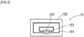
- RFID tag 15 is an electronic component having IC chip 157 implemented on a surface of tag sheet 150 cut out from, for example, a PET (PolyEthylene Terephthalate) film, as in FIG. 3 .
- IC chip 157 implemented on a surface of tag sheet 150 cut out from, for example, a PET (PolyEthylene Terephthalate) film, as in FIG. 3 .
- a printed pattern of loop coil 151 and antenna 153 is provided on the surface of tag sheet 150.
- Loop coil 151 is a receiving coil where an exciting current are generated by external electromagnetic induction.
- Antenna 153 is a transmission antenna for wireless transmission of the tag ID and so forth.
- a wireless tag of a UHF band is preferably adopted.
- Server apparatus 18 is a computer apparatus configured mainly by electronic substrate 180 having implemented thereon electronic components such as CPU (Central Processing Unit) 181, ROM (Read Only Memory) 182, and RAM (Random Access Memory) 183, as in FIG. 4 .
- electronic substrate 180 storage device 185 such as a hard disk drive, wireless communication unit 189, and so forth are connected via I/O (Input/Output) 184.
- Server apparatus 18 includes following functions as respective parts.
- the functions of the respective parts (2.1) to (2.3) are achieved by CPU 181 processing software programs read from storage device 185.
- the functions of the respective parts (2.4) to (2.6) are achieved by using storage areas of RAM 183 and storage device 185.
- Working vehicle 5 is, for example, a vehicle having a vehicle width on the order of 3 m and an overall length on the order of 8 m.
- Working vehicle 5 can be loaded with a container having a width of 2.4 m and a length of 6 m.
- Working vehicle 5 includes two front wheels to be steered and two rear driving wheels.
- the wheels to be steered are steered as being driven by a steering actuator.
- the driving wheels are driven by a drive motor.
- Working vehicle 5 includes, as in FIG. 5 and FIG. 6 , detection unit 2 which detects magnetic marker 10 and so forth, tag reader unit 34 which acquires the tag ID from RFID tag 15, vehicle onboard control unit 32, and so forth. Furthermore, working vehicle 5 includes vehicle ECU (Electric Control Unit) 61 which controls the drive motor, a brake actuator, the steering actuator, and so forth. Vehicle ECU 61 can perform control of causing working vehicle 5 to automatically travel along the route information received from server apparatus 18. Note that while detection unit 2 and tag reader unit 34 are depicted as separate bodies for ease of understanding, a unit with these units integrated may be adopted.
- detection unit 2 and tag reader unit 34 are depicted as separate bodies for ease of understanding, a unit with these units integrated may be adopted.
- Detection unit 2 is, as in FIG. 5 and FIG. 6 , a rod-shaped unit having sensor array 21 as a magnetism detecting part and IMU (Inertial Measurement Unit) 22 integrated together.
- This detection unit 2 is attached, in a state of facing road surface 100S, to a front part of a vehicle body of working vehicle 5.
- an attachment height of detection unit 2 with reference to road surface 100S is 200 mm.
- Sensor array 21 of detection unit 2 includes fifteen magnetic sensors Cn (n is an integer from 1 to 15) arrayed on a straight line and detection processing circuit 212 having incorporated therein a CPU and so forth not depicted.
- fifteen magnetic sensors Cn are equidistantly arranged with 10-centimeter pitches .
- Detection unit 2 is attached to working vehicle 5 so that the direction of arraying magnetic sensors Cn in sensor array 21 matches a vehicle-width direction.
- Magnetic sensor Cn are sensors which detect magnetism by using the known MI effect (Magneto Impedance Effect) in which the impedance of a magneto-sensitive body such as an amorphous wire sensitively changes in response to an external magnetic field.
- MI effect Magnetic Impedance Effect
- magneto-sensitive bodies such as amorphous wires not depicted are arranged along two directions orthogonal to each other, thereby allowing detection of magnetism acting in the two directions orthogonal to each other.
- magnetic sensors Cn are incorporated in sensor array 21 so as to be able to detect magnetic components in the forwarding direction and the vehicle-width direction.
- Magnetic sensors Cn are highly-sensitive sensors having a measurement range of the magnetic flux density of ⁇ 0.6 mT and a magnetic flux resolution of 0.02 ⁇ T within the measurement range.
- magnetic marker 10 can act magnetism having the magnetic flux density equal to or higher than 8 ⁇ T in a range of 100 mm to 250 mm assumed as the attachment height of magnetic sensors Cn. With magnetic marker 10 which acts magnetism equal or higher than the magnetic flux density of 8 ⁇ T, detection can be made with high reliability by using magnetic sensors Cn having the magnetic flux resolution of 0.02 ⁇ T.
- Detection processing circuit 212 ( FIG. 6 ) of sensor array 21 is an arithmetic circuit which performs a marker detection process for detecting magnetic marker 10.
- This detection processing circuit 212 is configured by using a CPU which performs various calculations as well as memory elements such as a ROM and RAM, and so forth.
- Detection processing circuit 212 acquires a sensor signal outputted from each of magnetic sensors Cn in a cycle of 3 kHz, performs the marker detection process, and then inputs detection result of the marker detection process to vehicle onboard control unit 32.
- detection process of which description will be made in detail further below, in addition to detection of magnetic marker 10, detection of the magnetic polarity of magnetic marker 10 and measurement of a lateral shift amount of working vehicle 5 with respect to magnetic marker 10, and so forth are performed.
- IMU 22 incorporated in detection unit 2 is a unit for inertial navigation. IMU 22 obtains measurement values required for estimation of a relative position of working vehicle 5 by inertial navigation. IMU 22 includes biaxial magnetic sensor 221 as an electronic compass which measures an azimuth, biaxial acceleration sensor 222 which measures acceleration, and biaxial gyro sensor 223 which measures angular velocity.
- Tag reader unit 34 of FIG. 6 is a communication unit which wirelessly communicates with RFID tag 15 laminated and arranged on the surface of magnetic marker 10 ( FIG. 2 ).
- Tag reader unit 34 wirelessly transmits electric power required for operation of RFID tag 15 to cause RFID tag 15 to operate, and acquires the tag ID (tag information) as identification information of RFID tag 15.
- Vehicle onboard control unit 32 ( FIG. 6 ) is a unit which controls detection unit 2 and tag reader unit 34 and also performs control for causing working vehicle 5 to perform automatic traveling.
- Vehicle onboard control unit 32 includes, in addition to a CPU not depicted, storage elements such as a ROM, RAM, and a flash ROM.
- Vehicle onboard control unit 32 achieves functions as the following respective means.
- the functions of the respective parts (3.3.1) to (3.3.5) are achieved by CPU processing software programs.
- the functions of the respective parts (3.3.6) and (3.3.7) are achieved by using storage areas of the storage elements.
- a route as a target for taking the marker passing count a route with a point whose position is identified taken as a starting point (reference) is set.
- the starting point can be, in addition to the departure point, a left-turn point, a right-turn point, and so forth of working vehicle 5, tag-equipped marker 10 with its address identifiable by using the tag information, and so forth.
- these points can be the starting point of the route as the target for taking the marker passing count.
- the marker detection process is a process to be performed by sensor array 21 of detection unit 2.
- Sensor array 21 performs the marker detection process by using magnetic sensors Cn in the cycle of 3 kHz. Note that when magnetic marker 10 is detected, a process of reading tag information is performed by tag reader unit 34.
- magnetic sensors Cn are configured to measure magnetic components in the forwarding direction and the vehicle-width direction of working vehicle 5. For example, when these magnetic sensors Cn move in the forwarding direction to pass directly above magnetic marker 10, a magnetic measurement value in the forwarding direction has its sign reversed before and after magnetic marker 10 as in FIG. 7 and changes so as to cross zero at a position directly above magnetic marker 10. Therefore, during traveling of working vehicle 5, when zero-cross Zc occurs in which the sign of the magnetic measurement value in the forwarding direction detected by any magnetic sensor Cn is reversed, it can be determined that detection unit 2 is positioned directly above magnetic marker 10. Detection processing circuit 212 determines that magnetic marker 10 is detected when detection unit 2 is positioned directly above magnetic marker 10 and zero-cross Zc of the magnetic measurement value in the forwarding direction occurs as described above.
- the magnetic measurement value in the vehicle-width direction has its sign reversed on both sides across magnetic marker 10 and changes so as to cross zero at a position directly above magnetic marker 10.
- the sign of the magnetic measurement value in the vehicle-width direction to be detected by magnetic sensor Cn varies depending on which side the magnetic sensor Cn is present with respect to magnetic marker 10 ( FIG. 8 ).
- FIG. 8 is a diagram exemplarily depicting a distribution of magnetic measurement values of respective magnetic sensors Cn of detection unit 2 in the vehicle-width direction. Based on the distribution of that drawing, an intermediate position between adjacent two magnetic sensors Cn across zero-cross Zc where the sign of the magnetic measurement value in the vehicle-width direction is reversed, or a position directly below magnetic sensor Cn where the detected magnetic measurement value in the vehicle-width direction is zero and the signs of the magnetic measurement values of magnetic sensors Cn on both outer sides are reversed, is a position of magnetic marker 10 in the vehicle-width direction.
- Detection processing circuit 212 measures a deviation of the position of magnetic marker 10 in the vehicle-width direction with respect to the center position (position of magnetic sensor C8) of detection unit 2 as the above-described lateral shift amount.
- the position of zero-cross Zc is a position corresponding to C9.5 in the neighborhood of a midpoint between C9 and C10.
- detection processing circuit 212 detects the magnetic polarity of magnetic marker 10 in accordance with the position relation between a positive sign and a negative sign on both sides of zero-cross Zc.
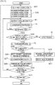
- FIG. 9 is a flow diagram depicting a flow of a remote control start process by server apparatus 18.
- FIG. 10 exemplarily depicts automatic traveling route 1R calculated by this start process.
- FIG. 11 is a flow diagram depicting a flow of automatic traveling control to be performed by working vehicle 5 while being remotely controlled.
- FIG. 12 is a flow diagram depicting a flow of a process to be performed by server apparatus 18 during remote control.
- description is made to an example of a process operation when working vehicle 5 conveys container 102 from marshalling yard 105 toward loading/unloading area 107.
- server apparatus 18 presents a work detail input screen, not depicted, to a work operator for setting predetermined details of a work to be performed by working vehicle 5.
- this work detail input screen for example, by operating an input device such as a mouse or a keyboard, it is possible to input details of the work to be performed by working vehicle 5.
- the details of the work include information about the receiving place where working vehicle 5 receives containers 102, the delivery place where working vehicle 5 delivers containers 102, and so forth.
- As the receiving place and the delivery place for example, it is possible to designate the address of magnetic marker 10 in marshalling yard 105 or loading/unloading area 107.
- server apparatus 18 first sets a destination in accordance with the details of the work including the receiving place, the delivery place, and so forth inputted by the work operator on the work detail input screen (S101). Subsequently, server apparatus 18 calculates automatic traveling route 1R for moving to the destination set at step S101 described above (S102).
- this receiving place is the destination of working vehicle 5. Also, in a period after containers 102 are loaded at the receiving place until working vehicle 5 arrives at the delivery place, this delivery place is the destination of working vehicle 5. Note that the current location of working vehicle 5 serving as the departure point for remote control is stored by server apparatus 18 as a final arrival place (absolute position) at the time of the previous remote control.
- the address where each magnetic marker 10 is positioned is a stop location of working vehicle 5. Therefore, the current location of working vehicle 5 can be identified by shifting the absolute position of magnetic marker 10 at the stop location by a relative position such as the lateral shift amount of working vehicle 5 with respect to magnetic marker 10 at the stop location or the movement amount after this magnetic marker 10 is detected.
- Automatic traveling route 1R is a route from magnetic marker 10 at an address (receiving place) on the 8th row and the 14th column in marshalling yard 105 as the starting point to a destination (delivery place) on the 14th row and the 30th column in loading/unloading area 107 by traveling in a straight line along the row and turning left at an address on the 8th row and the 30th column as a left-turn point.
- server apparatus 18 Upon calculating automatic traveling route 1R as at step S102 described above, server apparatus 18 transmits, toward working vehicle 5, the route information indicating this automatic traveling route 1R (S103).
- This route information includes information about the address on the 8th row and the 14th column corresponding to the departure point, the address on the 8th row and the 30th column as the left-turn point, and the address on the 14th row and the 30th column as the destination.
- vehicle onboard control unit 32 of working vehicle 5 Upon receiving the above-described route information, as in FIG. 11 , vehicle onboard control unit 32 of working vehicle 5 first sets the straight arrival point at which working vehicle 5 can arrive by traveling in a straight line from the departure point along the row or the column (S201) . In the case of the above-described route information, vehicle onboard control unit 32 sets the left-turn point (the 8th row and the 30th column) at which working vehicle 5 can arrive by traveling in the straight line from the departure point (the 8th row and the 14th column) along the row as the straight arrival point. Furthermore, newly setting the straight arrival point, vehicle onboard control unit 32 resets each of the above-described four types of the marker passing counts ((N-N), (S-S), (N-S), (S-N)) to zero (S202).
- vehicle onboard control unit 32 starts automatic traveling control P1 for traveling toward the straight arrival point (the 8th row and the 30th column) set at step S201 described above.
- this automatic traveling control P1 in addition to azimuth control of working vehicle 5 for traveling along the 8th row, the results of azimuth estimation and relative position estimation by inertial navigation are utilized.
- marker detection process P2 when magnetic marker 10 is detected includes measurement of the lateral shift amount with respect to magnetic marker 10, detection of the magnetic polarity of detected magnetic marker 10, and so forth.
- vehicle onboard control unit 32 When new magnetic marker 10 is detected (S203: YES), vehicle onboard control unit 32 first determines whether a combination of the magnetic polarity of immediately-previous magnetic marker 10 and the magnetic polarity of newly-detected magnetic marker 10 is appropriate (S204) . For example, in the case of automatic traveling route 1R ( FIG. 10 ) along the 8th row where N-pole magnetic markers 10N are arrayed as described above, N-pole magnetic markers 10N are supposed to be consecutively detected. Thus, if the magnetic polarities of immediately-previous magnetic marker 10 and newly-detected magnetic marker 10 are both the N pole, vehicle onboard control unit 32 determines that the magnetic polarity combination is appropriate (S204: YES).
- vehicle onboard control unit 32 controls tag reader unit 34 to cause tag reading process P3 for reading tag information to be performed. For example, since magnetic marker 10 on the 8th row and the 15th column immediately after departure from the starting point does not have RFID tag 15 annexed thereto, it is impossible to read tag information. If the tag information cannot be read, that is, if newly-detected magnetic marker 10 is non-tag marker 10 (S204: NO), vehicle onboard control unit 32 increments the marker passing count stored in marker history storage part 321 described above by one (S216). Note that, as described above, there are four types of marker passing counts corresponding to magnetic polarity combinations. At step S216 described above, the marker passing count corresponding to the magnetic polarity combination determined at step S204 described above is incremented by one.
- vehicle onboard control unit 32 identifies newly-detected magnetic marker 10 by using this marker passing count (S217). For example, when working vehicle 5 travels along a N-pole row to a direction in which the column number ascends (column ascending direction), vehicle onboard control unit 32 identifies an address obtained by adding the (N-N) marker passing count to the column number at the address (the 8th row and the 14th column) corresponding to the departure point as the address of newly-detected magnetic marker 10 (second position identifying part).
- vehicle onboard control unit 32 When working vehicle 5 is automatically traveling, vehicle onboard control unit 32 performs the process from step S203: YES to S217 described above whenever detecting non-tag marker 10 and increments the marker passing count by one. For example, when the working vehicle moves from the address on the 8th row and the 14th column as the starting point along the row and the (N-N) marker passing count indicates three in response to detection of magnetic markers 10, vehicle onboard control unit 32 increments the column number of the address of the starting point, the 8th row and the 14th column, by three, thereby identifying magnetic marker 10 on the 8th row and the 17th column.
- vehicle onboard control unit 32 identifies detected tag-equipped marker 10 (S206, first position identifying part). Also, vehicle onboard control unit 32 sets detected tag-equipped marker 10 as the starting point of a new route, and resets all of the marker passing counts to zero (S207).
- step S205 NO onward described above, tag-equipped marker 10 is merely handled as non-tag marker 10. In this manner, in the process of working vehicle 5 depicted in FIG. 11 , the process does not fail due to a failure in tag information reading. This handling is similarly applied to the process of server apparatus 18 in FIG. 12 , which will be described further below.
- vehicle onboard control unit 32 If detected magnetic marker 10 has been identified irrespective of whether the marker is tag-equipped marker 10 or non-tag marker 10, vehicle onboard control unit 32 generates the marker detection information and transmits this information to server apparatus 18 (S208).
- This marker detection information includes information indicating that magnetic marker 10 has been detected, information about the magnetic polarity of magnetic marker 10, and the tag ID (tag information) in the case of tag-equipped marker 10.
- vehicle onboard control unit 32 determines whether working vehicle 5 has arrived at the straight arrival point set at step S201 described above (S209). Specifically, it is determined whether the address of magnetic marker 10 identified at step S206 or step S217 described above matches the address of the straight arrival point.
- vehicle onboard control unit 32 continues automatic traveling control P1, and repeatedly performs the process at step S203 onward described above subsequently to marker detection process P2.
- vehicle onboard control unit 32 determines whether that straight arrival point is the destination (S210). If working vehicle 5 has arrived at the destination (S210: YES), automatic traveling control ends.
- vehicle onboard control unit 32 If working vehicle 5 has arrived at the straight arrival point that is not the destination (S210: NO), vehicle onboard control unit 32 returns to step S201 described above and sets a new straight arrival point. Furthermore, vehicle onboard control unit 32 resets each marker passing count to zero for setting magnetic marker 10 corresponding to the position of working vehicle 5 at that time as the starting point of a route to the new straight arrival point (S202), and then continues automatic traveling control P1.
- the left-turn point on the 8th row and the 30th column is the straight arrival point. Furthermore, after passing this left-turn point, the address on the 14th row and the 30th column as the destination is the straight arrival point.
- server apparatus 18 waits for reception of the marker detection information transmitted from working vehicle 5 (S301: NO). Then, whenever receiving the marker detection information (S301: YES), server apparatus 18 determines whether the tag ID (tag information) is included (S302) . When the tag ID is included (S302: YES), server apparatus 18 refers to marker DB 185M by using that tag ID, and identifies the position of the corresponding magnetic marker 10 (S303). Then, server apparatus 18 stores and manages the address (position) of identified magnetic marker 10 as the vehicle position of working vehicle 5.
- server apparatus 18 identifies, as newly-detected magnetic marker 10, any of four magnetic markers 10 adjacent to one another in the row direction or the column direction with respect to the vehicle position of working vehicle 5 (address of magnetic marker 10) stored on the area map (S313).
- magnetic marker 10 detected by working vehicle 5 is any of two magnetic markers 10, that is, magnetic marker 10 positioned on a column-number ascending side and magnetic marker 10 positioned on a row-number ascending side.
- the magnetic polarity of magnetic marker 10 (previously-detected magnetic marker 10) corresponding to the vehicle position stored in server apparatus 18 and the magnetic polarity of newly-detected magnetic marker 10, either of the two magnetic markers 10 described above can be selected in a determined manner.
- the magnetic polarity combination of previously-detected magnetic marker 10 and newly-detected magnetic marker 10 is an N-pole-N-pole or an S-pole-S-pole combination
- magnetic marker 10 adjacent along the row can be identified as new magnetic marker 10.
- magnetic marker 10 adjacent along the column can be identified as new magnetic marker 10.
- server apparatus 18 Upon identifying magnetic marker 10 newly detected by working vehicle 5 as at step S303 or S313 described above, server apparatus 18 stores and manages the address of that magnetic marker 10 as the vehicle position of working vehicle 5 (S304). Furthermore, server apparatus 18 determines whether the newly stored vehicle position is on automatic traveling route 1R ( FIG. 10 ) calculated at step S102 ( FIG. 9 ) described above (S305). If working vehicle 5 is not positioned on automatic traveling route 1R (S305: NO), the process proceeds to error process E2. Note that, as error process E2, it is preferable to adopt, for example, the process of stopping working vehicle 5 and calling an operator.
- server apparatus 18 determines whether working vehicle 5 has arrived at the destination (S306). Then, if the working vehicle 5 has arrived at the destination, server apparatus 18 ends remote control (S306: YES). On the other hand, if working vehicle 5 is short of the destination, server apparatus 18 waits for reception of new marker detection information from working vehicle 5 (S306: NO). Then, if receiving marker detection information, server apparatus 18 performs the process subsequent to step S301 described above.
- RFID tag (wireless tag) 15 which outputs tag information is annexed to some of magnetic markers 10.
- magnetic marker 10 can be identified by using the tag ID included in the tag information, thereby allowing the vehicle position to be identified (first position identifying part).
- magnetic markers 10 are arranged in a predetermined pattern in which the magnetic polarity is different for each row of passages 108 forming a grid shape.
- working vehicle system 1 in accordance with the combination of magnetic polarities of magnetic markers 10 detected by working vehicle 5, it is possible to identify whether working vehicle 5 has traveled along the row or along the column.
- the magnetic polarity combination of N pole ⁇ N pole in which N-pole magnetic marker 10N is detected subsequently to detection of N-pole magnetic marker 10N corresponds to traveling of working vehicle 5 along the row.
- Working vehicle system 1 configured as described above is a system allowing the position of working vehicle 5 in working area 1A to be identified with high reliability, and can perform management, control, and so forth of working vehicles 5 moving in working area 1A with high reliability.
- This working vehicle system 1 can identify the vehicle positions of working vehicles 5 without presuming reception of GPS radio waves or the like. Thus, for example, even in a place alongside berthing container ships 101 or containers 102, and a place below crane 103 or the like where GPS radio waves become unstable, or in a facility at a harbor or the like where GPS accuracy may be intentionally suppressed, accuracy of identifying the vehicle position is not affected. With the use of the vehicle position identified by working vehicle system 1, the location of working vehicle 5 can be managed with high accuracy, and reliable remote control can be achieved.
- a processing apparatus inputting delivery information of containers 102 may determine necessary work by, for example, an artificial intelligence process and, in accordance with the determination, may determine the work details of each working vehicle 5.
- a unit which detects the orientation of working vehicle 5 by using the rotation speed or the number of rotations for each wheel of four wheels included in working vehicle 5, or the steering angle of the steering wheel or the wheels to be steered.
- the rotation speed, the number of rotations, and so forth of each wheel can be measured by a relatively simple configuration in which a rotation sensor or the like is attached to each wheel.
- the configuration is exemplarily depicted in which working vehicle 5 receiving the route information from server apparatus 18 autonomously travels.
- a configuration may be adopted in which server apparatus 18 remotely controls working vehicles 5 for automatic traveling.
- marker DB 185M in which laying positions of magnetic markers 10 are managed each linked to the tag ID of RFID tag 15, is provided to a server apparatus 18 side and each working vehicle 5 includes vehicle onboard marker DB 320 identical to marker DB 185M. In place of this, it may be configured such that each working vehicle 5 accesses marker DB 185M of server apparatus 18 via wireless communication.
- the configuration of identifying the vehicle position of each working vehicle 5 in working vehicle system 1 of the present embodiment is useful not only for a system in which working vehicles 5 are caused to automatically travel by remote control or autonomous control, but also for a system for managing, on the server apparatus 18 side with high accuracy, the position of working vehicle 5 being driven by a worker.
- server apparatus 18 stores the vehicle position of working vehicle 5 and updates that vehicle position as occasion arises when the new magnetic marker 10 is detected.
- detection history of magnetic markers 10 by working vehicle 5 may be stored in server apparatus 18.
- the detection history history of magnetic polarity combinations of the previously-detected magnetic marker and the newly-detected magnetic marker may be stored.
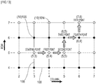
- the detection history of FIG. 14 is recorded.
- Numbers in the drawing are numbers representing a temporal order, with No. 1 corresponding to the temporally oldest history.
- an (N-N) history of No. 2 represents a movement along the 5th row of detecting N-pole magnetic marker 10N on the 5th row and the 4th column and then N-pole magnetic marker 10N on the 5th row and the 5th column.
- an (S-N) history of No. 5 represents a movement along the 6th column of detecting S-pole magnetic marker 10S on the 6th row and the 6th column and then N-pole magnetic marker 10N on the 7th row and the 6th column.
- the history count without switching of magnetic polarity such as (N-N) and (S-S)
- the history count with switching of magnetic polarity such as (N-S) and (S-N)
- the history count without switching of magnetic polarity is three
- the history count with switching of magnetic polarity is two.
- the history without switching of magnetic polarity is the history corresponding to movements along the row direction
- the history with switching of magnetic polarity is the history corresponding to movements along the column direction. Therefore, a movement with the history count without switching of magnetic polarity of three and a history count with switching of magnetic polarity of two corresponds to, as in FIG.
- working vehicle 5 arrives at magnetic marker 10 on the 7th row and the 6th column by taking magnetic marker 10 on the 5th row and the 3rd column as the starting point.
- the moving directions of working vehicle 5 are limited to two directions, that is, the direction in which the column number ascends along the row direction (column-ascending direction) and the direction in which the row number ascends along the column direction (row-ascending direction) .
- the configuration may be such that working vehicle 5 can move to four directions, that is, upward, downward, leftward, and rightward directions, along the passages 108 in the grid shape.
- moving direction is preferably recorded in addition to each of the histories of No. 1 to No. 5 exemplarily depicted in FIG. 14 .
- the azimuth information may be information based on, for example, the azimuth measured by IMU 22.
- an diagonally moving pattern may be added.
- An diagonal movement can be detected by using the azimuth measured by IMU 22.
- the diagonal movement may be allowed only when making a detour around another stopping working vehicle 5, crossing working vehicle 5 moving in an opposite direction, and so forth.
- the configuration may be such that the movement from marshalling yard 105 toward loading/unloading area 107 is achieved only by an diagonal movement and an oppositely oriented movement is achieved only by vertical and horizontal movements.
- overlapping sections of a movement route of working vehicle 5 moving from marshalling yard 105 toward the loading/unloading area 107 and a movement route of oppositely oriented working vehicle 5 are grid points only, and overlapping portions can be decreased. And, this can reduce the degree of interference between working vehicle 5 moving from marshalling yard 105 toward loading/unloading area 107 and oppositely oriented working vehicle 5, and can improve movement efficiency.
- container conveying works may be ranked.
- ranks include rush, normal, and so forth.
- shortest movement route including the diagonal movement is set for a rush conveying work
- a movement route only with vertical and horizontal movements is set for a normal conveying work. In this case, the movement distance required for the rush conveying work can be shortened, and the working time can be reduced.
- the magnetic polarity of magnetic markers 10 may be switched for each column, alternatively.
- the magnetic polarity patterns are not limited to these pattern. Any pattern in which the magnetic polarity is switched with constant regularity is relevant to the predetermined pattern.
- traveling area 1A provided with passages 108 in the grid shape has been exemplarily described, and, as shapes forming the grid, a grid of squares with 10-meter pitches in each of vertical and horizontal directions is exemplarily described.
- Shapes forming the grid are not limited to squares, and may be rectangles, parallelograms, rhombus, triangles, or the like.
- the magnetic marker is preferably arranged at each grid point forming an apex of each shape of the grid.
- the size of the shape of the grid the size with 10-m pitches in each of vertical and horizontal directions has been exemplarily described.
- a plurality of types of size may be set. For example, a configuration may be adopted in which while the size of the shape forming the grid on a sea side is set small, the size of the shape forming the grid on a land side is set large, or a configuration may be adopted in which while the size of the shape forming the grid in an area where containers are loaded/unloaded is set small, the size of the shape forming the grid in the other areas where working vehicles pass is set large. Still further, a rectangular grid shape in which the distance between rows and the distance between columns are different may be provided.
- the distance between columns may be set at, for example, 10 meters
- the distance between rows in an area where containers are loaded/unloaded may be finely set at, for example, 5 meters
- the distance between rows in the other areas where working vehicles pass may be coarsely set at, for example, 10 meters.
- the present embodiment is an example in which the vehicular system of the first embodiment is applied to a road where a vehicle travels. Details of this are described with reference to FIG. 17 and FIG. 18 .
- RFID tag 15 may be annexed to some of magnetic markers 10.
- an example based on the configuration of the first embodiment is depicted in which, as a vehicle traveling area, the road is assumed in which a vehicle moving direction is prescribed for each lane.
- a marker DB storing information regarding each magnetic marker 10 is preferably provided.
- information preferably stored are, in addition to the absolute position and the magnetic polarity of magnetic marker 10, the address indicated by an order number, a lane type such as a traveling lane or a passing lane, inbound/outbound information, and so forth.
- the information regarding tag-equipped marker 10 is preferably linked to (associated with) the tag ID (tag information), which is identification information of annexed RFID tag 15.
- the address of newly-detected magnetic marker 10 can be identified, thereby allowing the laying position and so forth to be identified.
- adoption of this configuration for example, even if reading of the tag information of tag-equipped marker 10 fails and the marker is detected as non-tag marker 10, the address of new magnetic marker 10 can be identified irrespective of the failure in reading the tag information.
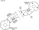
- the configuration of the vehicular system of the first embodiment may be applied to BRT (Bus Rapid Transit) exemplarily depicted in FIG. 18 for ensuring timeliness and reinforcing transport capacity by using a bus lane, a coupled bus, or the like.
- BRT Bus Rapid Transit
- N-pole magnetic markers 10N are arranged on an inbound route toward the urban area
- S-pole magnetic marker 10S are arranged on an outbound route toward the residential area.
- RFID tag 15 is annexed to some of magnetic markers 10 (magnetic markers each shown with a circle therearound in FIG. 18 ), as with the case of FIG.
- the address, the laying position, and so forth of each magnetic marker 10 is preferably managed in the marker DB.
- the marker passing count after passing of tag-equipped marker 10 it is possible to identify the address of newly-detected magnetic marker 10 and identify the laying position. Also, with repetition of detection of magnetic marker 10 with the same magnetic polarity, a movement of the bus along the inbound or outbound route can be confirmed.
Landscapes
- Engineering & Computer Science (AREA)
- Radar, Positioning & Navigation (AREA)
- Remote Sensing (AREA)
- Physics & Mathematics (AREA)
- General Physics & Mathematics (AREA)
- Automation & Control Theory (AREA)
- Aviation & Aerospace Engineering (AREA)
- Electromagnetism (AREA)
- Control Of Position, Course, Altitude, Or Attitude Of Moving Bodies (AREA)
Applications Claiming Priority (2)
| Application Number | Priority Date | Filing Date | Title |
|---|---|---|---|
| JP2018139012A JP7115098B2 (ja) | 2018-07-25 | 2018-07-25 | 車両用システム |
| PCT/JP2019/028373 WO2020022196A1 (fr) | 2018-07-25 | 2019-07-18 | Système pour véhicule |
Publications (3)
| Publication Number | Publication Date |
|---|---|
| EP3828659A1 true EP3828659A1 (fr) | 2021-06-02 |
| EP3828659A4 EP3828659A4 (fr) | 2022-04-06 |
| EP3828659B1 EP3828659B1 (fr) | 2024-02-21 |
Family
ID=69181666
Family Applications (1)
| Application Number | Title | Priority Date | Filing Date |
|---|---|---|---|
| EP19841688.5A Active EP3828659B1 (fr) | 2018-07-25 | 2019-07-18 | Système pour véhicule |
Country Status (6)
| Country | Link |
|---|---|
| US (1) | US11687088B2 (fr) |
| EP (1) | EP3828659B1 (fr) |
| JP (1) | JP7115098B2 (fr) |
| CN (1) | CN112513764B (fr) |
| SG (1) | SG11202100595XA (fr) |
| WO (1) | WO2020022196A1 (fr) |
Cited By (2)
| Publication number | Priority date | Publication date | Assignee | Title |
|---|---|---|---|---|
| US11294090B2 (en) * | 2017-03-28 | 2022-04-05 | Aichi Steel Corporation | Marker detection system and marker detection method |
| US20240288283A1 (en) | 2021-06-25 | 2024-08-29 | Aichi Steel Corporation | Magnetic marker detection method and detection system |
Families Citing this family (6)
| Publication number | Priority date | Publication date | Assignee | Title |
|---|---|---|---|---|
| US11604476B1 (en) * | 2018-10-05 | 2023-03-14 | Glydways Inc. | Road-based vehicle guidance system |
| US20210382498A1 (en) * | 2020-06-09 | 2021-12-09 | Thomas Philip Ramstack | Mobility assist apparatus and method |
| EP4174230A4 (fr) * | 2020-06-26 | 2024-07-17 | Aichi Steel Corporation | Système orienté véhicule, et procédé de lecture d'informations |
| CN117063215A (zh) * | 2021-04-01 | 2023-11-14 | 爱知制钢株式会社 | 信息取得方法以及车辆用系统 |
| JP7815776B2 (ja) * | 2022-01-17 | 2026-02-18 | 株式会社豊田自動織機 | 位置特定装置 |
| JPWO2024247673A1 (fr) * | 2023-05-30 | 2024-12-05 |
Family Cites Families (15)
| Publication number | Priority date | Publication date | Assignee | Title |
|---|---|---|---|---|
| NL8500529A (nl) | 1985-02-25 | 1986-09-16 | Ind Contractors Holland Bv | Stelsel voor het bepalen van de positie van een niet aan een vaste baan gebonden voertuig. |
| JPH06265615A (ja) * | 1993-03-16 | 1994-09-22 | Mazda Motor Corp | 路上情報検知装置 |
| JP3359008B2 (ja) * | 1999-08-20 | 2002-12-24 | 三菱重工業株式会社 | 無人搬送車の走行制御システム |
| JP2001322720A (ja) | 2000-05-16 | 2001-11-20 | Tcm Corp | コンテナ荷役方法およびコンテナ荷役システム |
| JP2004255529A (ja) * | 2003-02-26 | 2004-09-16 | Sony Corp | ロボット装置およびロボット装置の制御方法、並びにロボット装置移動制御システム |
| JP2006065703A (ja) * | 2004-08-30 | 2006-03-09 | Inst Of Systems Information Technologies Kyushu | 自己位置推定装置、自己位置推定方法、その自己位置推定方法をコンピュータに実行させることが可能なプログラム、及び、そのプログラムを記録した記録媒体 |
| JP4379439B2 (ja) * | 2006-06-27 | 2009-12-09 | 株式会社豊田自動織機 | 位置検出システム |
| KR101151990B1 (ko) | 2010-01-08 | 2012-06-01 | 성균관대학교산학협력단 | 마그네틱 랜드마크를 이용한 모바일 로봇의 전역 위치 추정 및 보정 방법 |
| JP5344504B2 (ja) | 2012-02-20 | 2013-11-20 | ニチユ三菱フォークリフト株式会社 | 無人搬送システム |
| CN102682620B (zh) | 2012-05-23 | 2015-08-12 | 上海海事大学 | 集装箱港口车辆运行状态感知与定位系统以及方法 |
| US9197705B2 (en) | 2013-04-12 | 2015-11-24 | Samsung Electronics Co., Ltd. | Method and apparatus for supporting driving using wireless communication network and system thereof |
| KR101704192B1 (ko) * | 2015-04-29 | 2017-02-08 | 목포대학교산학협력단 | 십자형 구조의 자계위치센서 유닛을 갖는 이동 로봇 |
| CN109074732B (zh) | 2016-04-28 | 2021-11-02 | 爱知制钢株式会社 | 驾驶支援系统 |
| CN106249736B (zh) * | 2016-07-13 | 2020-05-08 | 上海交通大学 | 一种基于磁钉地图导航的自动导引车 |
| CN107160397B (zh) | 2017-06-09 | 2023-07-18 | 浙江立镖机器人有限公司 | 机器人行走的模块地标、地标及其机器人 |
-
2018
- 2018-07-25 JP JP2018139012A patent/JP7115098B2/ja active Active
-
2019
- 2019-07-18 WO PCT/JP2019/028373 patent/WO2020022196A1/fr not_active Ceased
- 2019-07-18 SG SG11202100595XA patent/SG11202100595XA/en unknown
- 2019-07-18 US US17/261,590 patent/US11687088B2/en active Active
- 2019-07-18 CN CN201980047609.5A patent/CN112513764B/zh active Active
- 2019-07-18 EP EP19841688.5A patent/EP3828659B1/fr active Active
Cited By (4)
| Publication number | Priority date | Publication date | Assignee | Title |
|---|---|---|---|---|
| US11294090B2 (en) * | 2017-03-28 | 2022-04-05 | Aichi Steel Corporation | Marker detection system and marker detection method |
| US20240288283A1 (en) | 2021-06-25 | 2024-08-29 | Aichi Steel Corporation | Magnetic marker detection method and detection system |
| EP4361553A4 (fr) * | 2021-06-25 | 2025-10-01 | Aichi Steel Corp | Procédé de détection de marqueur magnétique et système de détection |
| US12607485B2 (en) | 2021-06-25 | 2026-04-21 | Aichi Steel Corporation | Magnetic marker detection method and detection system |
Also Published As
| Publication number | Publication date |
|---|---|
| WO2020022196A1 (fr) | 2020-01-30 |
| US11687088B2 (en) | 2023-06-27 |
| SG11202100595XA (en) | 2021-02-25 |
| EP3828659B1 (fr) | 2024-02-21 |
| US20210271261A1 (en) | 2021-09-02 |
| JP2020017035A (ja) | 2020-01-30 |
| JP7115098B2 (ja) | 2022-08-09 |
| EP3828659A4 (fr) | 2022-04-06 |
| CN112513764B (zh) | 2024-10-15 |
| CN112513764A (zh) | 2021-03-16 |
Similar Documents
| Publication | Publication Date | Title |
|---|---|---|
| EP3828659B1 (fr) | Système pour véhicule | |
| US11119499B2 (en) | Marker system | |
| US20210254978A1 (en) | Module fiducial markers for robot navigation, address markers and the associated robots | |
| WO2019156194A1 (fr) | Système de véhicule | |
| ES2198337T3 (es) | Procedimiento y dispositivo para la deteccion de la posicion de un vehiculo en una zona especificada. | |
| US11287263B2 (en) | Position capturing system and position capturing method | |
| EP3904991B1 (fr) | Véhicule et système de diagnostic de véhicule | |
| US20210215507A1 (en) | Gyro sensor calibration method | |
| EP4174608A1 (fr) | Système de marqueur et procédé de détection de marqueur magnétique | |
| CN109282821B (zh) | 一种园区导航方法和系统 | |
| JP2018169301A (ja) | マーカシステム | |
| EP4194305A1 (fr) | Système d'actionnement et procédé de commande pour système d'actionnement | |
| JP2019067353A (ja) | 車両用システム及びタグ通信方法 | |
| US12559353B2 (en) | Determining position of a container handling equipment | |
| WO2019065176A1 (fr) | Système de véhicule et procédé de communication d'étiquette | |
| US12602055B2 (en) | Vehicular system | |
| US12322285B2 (en) | Information acquisition method and vehicular system | |
| US20240400046A1 (en) | Control method and control system | |
| Kawabata et al. | Vehicle Guidance System using Local Information Assistants | |
| Kawabata¹ et al. | Vehicle Guidance System using Local |
Legal Events
| Date | Code | Title | Description |
|---|---|---|---|
| STAA | Information on the status of an ep patent application or granted ep patent |
Free format text: STATUS: THE INTERNATIONAL PUBLICATION HAS BEEN MADE |
|
| PUAI | Public reference made under article 153(3) epc to a published international application that has entered the european phase |
Free format text: ORIGINAL CODE: 0009012 |
|
| STAA | Information on the status of an ep patent application or granted ep patent |
Free format text: STATUS: REQUEST FOR EXAMINATION WAS MADE |
|
| 17P | Request for examination filed |
Effective date: 20210118 |
|
| AK | Designated contracting states |
Kind code of ref document: A1 Designated state(s): AL AT BE BG CH CY CZ DE DK EE ES FI FR GB GR HR HU IE IS IT LI LT LU LV MC MK MT NL NO PL PT RO RS SE SI SK SM TR |
|
| DAV | Request for validation of the european patent (deleted) | ||
| DAX | Request for extension of the european patent (deleted) | ||
| A4 | Supplementary search report drawn up and despatched |
Effective date: 20220310 |
|
| RIC1 | Information provided on ipc code assigned before grant |
Ipc: G01C 21/34 20060101ALI20220303BHEP Ipc: G01C 21/28 20060101ALI20220303BHEP Ipc: G05D 1/02 20200101AFI20220303BHEP |
|
| STAA | Information on the status of an ep patent application or granted ep patent |
Free format text: STATUS: EXAMINATION IS IN PROGRESS |
|
| 17Q | First examination report despatched |
Effective date: 20221117 |
|
| GRAP | Despatch of communication of intention to grant a patent |
Free format text: ORIGINAL CODE: EPIDOSNIGR1 |
|
| STAA | Information on the status of an ep patent application or granted ep patent |
Free format text: STATUS: GRANT OF PATENT IS INTENDED |
|
| INTG | Intention to grant announced |
Effective date: 20230914 |
|
| P01 | Opt-out of the competence of the unified patent court (upc) registered |
Effective date: 20231110 |
|
| GRAS | Grant fee paid |
Free format text: ORIGINAL CODE: EPIDOSNIGR3 |
|
| GRAA | (expected) grant |
Free format text: ORIGINAL CODE: 0009210 |
|
| STAA | Information on the status of an ep patent application or granted ep patent |
Free format text: STATUS: THE PATENT HAS BEEN GRANTED |
|
| AK | Designated contracting states |
Kind code of ref document: B1 Designated state(s): AL AT BE BG CH CY CZ DE DK EE ES FI FR GB GR HR HU IE IS IT LI LT LU LV MC MK MT NL NO PL PT RO RS SE SI SK SM TR |
|
| REG | Reference to a national code |
Ref country code: GB Ref legal event code: FG4D |
|
| REG | Reference to a national code |
Ref country code: CH Ref legal event code: EP |
|
| REG | Reference to a national code |
Ref country code: IE Ref legal event code: FG4D |
|
| REG | Reference to a national code |
Ref country code: DE Ref legal event code: R096 Ref document number: 602019047039 Country of ref document: DE |
|
| REG | Reference to a national code |
Ref country code: NL Ref legal event code: FP |
|
| REG | Reference to a national code |
Ref country code: SE Ref legal event code: TRGR |
|
| REG | Reference to a national code |
Ref country code: LT Ref legal event code: MG9D |
|
| PG25 | Lapsed in a contracting state [announced via postgrant information from national office to epo] |
Ref country code: IS Free format text: LAPSE BECAUSE OF FAILURE TO SUBMIT A TRANSLATION OF THE DESCRIPTION OR TO PAY THE FEE WITHIN THE PRESCRIBED TIME-LIMIT Effective date: 20240621 |
|
| PG25 | Lapsed in a contracting state [announced via postgrant information from national office to epo] |
Ref country code: LT Free format text: LAPSE BECAUSE OF FAILURE TO SUBMIT A TRANSLATION OF THE DESCRIPTION OR TO PAY THE FEE WITHIN THE PRESCRIBED TIME-LIMIT Effective date: 20240221 |
|
| PG25 | Lapsed in a contracting state [announced via postgrant information from national office to epo] |
Ref country code: GR Free format text: LAPSE BECAUSE OF FAILURE TO SUBMIT A TRANSLATION OF THE DESCRIPTION OR TO PAY THE FEE WITHIN THE PRESCRIBED TIME-LIMIT Effective date: 20240522 |
|
| REG | Reference to a national code |
Ref country code: AT Ref legal event code: MK05 Ref document number: 1659644 Country of ref document: AT Kind code of ref document: T Effective date: 20240221 |
|
| PG25 | Lapsed in a contracting state [announced via postgrant information from national office to epo] |
Ref country code: HR Free format text: LAPSE BECAUSE OF FAILURE TO SUBMIT A TRANSLATION OF THE DESCRIPTION OR TO PAY THE FEE WITHIN THE PRESCRIBED TIME-LIMIT Effective date: 20240221 Ref country code: RS Free format text: LAPSE BECAUSE OF FAILURE TO SUBMIT A TRANSLATION OF THE DESCRIPTION OR TO PAY THE FEE WITHIN THE PRESCRIBED TIME-LIMIT Effective date: 20240521 |
|
| PG25 | Lapsed in a contracting state [announced via postgrant information from national office to epo] |
Ref country code: ES Free format text: LAPSE BECAUSE OF FAILURE TO SUBMIT A TRANSLATION OF THE DESCRIPTION OR TO PAY THE FEE WITHIN THE PRESCRIBED TIME-LIMIT Effective date: 20240221 |
|
| PG25 | Lapsed in a contracting state [announced via postgrant information from national office to epo] |
Ref country code: AT Free format text: LAPSE BECAUSE OF FAILURE TO SUBMIT A TRANSLATION OF THE DESCRIPTION OR TO PAY THE FEE WITHIN THE PRESCRIBED TIME-LIMIT Effective date: 20240221 |
|
| PG25 | Lapsed in a contracting state [announced via postgrant information from national office to epo] |
Ref country code: RS Free format text: LAPSE BECAUSE OF FAILURE TO SUBMIT A TRANSLATION OF THE DESCRIPTION OR TO PAY THE FEE WITHIN THE PRESCRIBED TIME-LIMIT Effective date: 20240521 Ref country code: NO Free format text: LAPSE BECAUSE OF FAILURE TO SUBMIT A TRANSLATION OF THE DESCRIPTION OR TO PAY THE FEE WITHIN THE PRESCRIBED TIME-LIMIT Effective date: 20240521 Ref country code: LT Free format text: LAPSE BECAUSE OF FAILURE TO SUBMIT A TRANSLATION OF THE DESCRIPTION OR TO PAY THE FEE WITHIN THE PRESCRIBED TIME-LIMIT Effective date: 20240221 Ref country code: IS Free format text: LAPSE BECAUSE OF FAILURE TO SUBMIT A TRANSLATION OF THE DESCRIPTION OR TO PAY THE FEE WITHIN THE PRESCRIBED TIME-LIMIT Effective date: 20240621 Ref country code: HR Free format text: LAPSE BECAUSE OF FAILURE TO SUBMIT A TRANSLATION OF THE DESCRIPTION OR TO PAY THE FEE WITHIN THE PRESCRIBED TIME-LIMIT Effective date: 20240221 Ref country code: GR Free format text: LAPSE BECAUSE OF FAILURE TO SUBMIT A TRANSLATION OF THE DESCRIPTION OR TO PAY THE FEE WITHIN THE PRESCRIBED TIME-LIMIT Effective date: 20240522 Ref country code: FI Free format text: LAPSE BECAUSE OF FAILURE TO SUBMIT A TRANSLATION OF THE DESCRIPTION OR TO PAY THE FEE WITHIN THE PRESCRIBED TIME-LIMIT Effective date: 20240221 Ref country code: ES Free format text: LAPSE BECAUSE OF FAILURE TO SUBMIT A TRANSLATION OF THE DESCRIPTION OR TO PAY THE FEE WITHIN THE PRESCRIBED TIME-LIMIT Effective date: 20240221 Ref country code: BG Free format text: LAPSE BECAUSE OF FAILURE TO SUBMIT A TRANSLATION OF THE DESCRIPTION OR TO PAY THE FEE WITHIN THE PRESCRIBED TIME-LIMIT Effective date: 20240221 Ref country code: AT Free format text: LAPSE BECAUSE OF FAILURE TO SUBMIT A TRANSLATION OF THE DESCRIPTION OR TO PAY THE FEE WITHIN THE PRESCRIBED TIME-LIMIT Effective date: 20240221 |
|
| PG25 | Lapsed in a contracting state [announced via postgrant information from national office to epo] |
Ref country code: PL Free format text: LAPSE BECAUSE OF FAILURE TO SUBMIT A TRANSLATION OF THE DESCRIPTION OR TO PAY THE FEE WITHIN THE PRESCRIBED TIME-LIMIT Effective date: 20240221 Ref country code: PT Free format text: LAPSE BECAUSE OF FAILURE TO SUBMIT A TRANSLATION OF THE DESCRIPTION OR TO PAY THE FEE WITHIN THE PRESCRIBED TIME-LIMIT Effective date: 20240621 |
|
| PG25 | Lapsed in a contracting state [announced via postgrant information from national office to epo] |
Ref country code: PT Free format text: LAPSE BECAUSE OF FAILURE TO SUBMIT A TRANSLATION OF THE DESCRIPTION OR TO PAY THE FEE WITHIN THE PRESCRIBED TIME-LIMIT Effective date: 20240621 Ref country code: PL Free format text: LAPSE BECAUSE OF FAILURE TO SUBMIT A TRANSLATION OF THE DESCRIPTION OR TO PAY THE FEE WITHIN THE PRESCRIBED TIME-LIMIT Effective date: 20240221 Ref country code: LV Free format text: LAPSE BECAUSE OF FAILURE TO SUBMIT A TRANSLATION OF THE DESCRIPTION OR TO PAY THE FEE WITHIN THE PRESCRIBED TIME-LIMIT Effective date: 20240221 |
|
| PG25 | Lapsed in a contracting state [announced via postgrant information from national office to epo] |
Ref country code: DK Free format text: LAPSE BECAUSE OF FAILURE TO SUBMIT A TRANSLATION OF THE DESCRIPTION OR TO PAY THE FEE WITHIN THE PRESCRIBED TIME-LIMIT Effective date: 20240221 |
|
| PG25 | Lapsed in a contracting state [announced via postgrant information from national office to epo] |
Ref country code: SM Free format text: LAPSE BECAUSE OF FAILURE TO SUBMIT A TRANSLATION OF THE DESCRIPTION OR TO PAY THE FEE WITHIN THE PRESCRIBED TIME-LIMIT Effective date: 20240221 |
|
| PG25 | Lapsed in a contracting state [announced via postgrant information from national office to epo] |
Ref country code: CZ Free format text: LAPSE BECAUSE OF FAILURE TO SUBMIT A TRANSLATION OF THE DESCRIPTION OR TO PAY THE FEE WITHIN THE PRESCRIBED TIME-LIMIT Effective date: 20240221 Ref country code: EE Free format text: LAPSE BECAUSE OF FAILURE TO SUBMIT A TRANSLATION OF THE DESCRIPTION OR TO PAY THE FEE WITHIN THE PRESCRIBED TIME-LIMIT Effective date: 20240221 |
|
| PG25 | Lapsed in a contracting state [announced via postgrant information from national office to epo] |
Ref country code: SK Free format text: LAPSE BECAUSE OF FAILURE TO SUBMIT A TRANSLATION OF THE DESCRIPTION OR TO PAY THE FEE WITHIN THE PRESCRIBED TIME-LIMIT Effective date: 20240221 |
|
| PG25 | Lapsed in a contracting state [announced via postgrant information from national office to epo] |
Ref country code: SM Free format text: LAPSE BECAUSE OF FAILURE TO SUBMIT A TRANSLATION OF THE DESCRIPTION OR TO PAY THE FEE WITHIN THE PRESCRIBED TIME-LIMIT Effective date: 20240221 Ref country code: SK Free format text: LAPSE BECAUSE OF FAILURE TO SUBMIT A TRANSLATION OF THE DESCRIPTION OR TO PAY THE FEE WITHIN THE PRESCRIBED TIME-LIMIT Effective date: 20240221 Ref country code: RO Free format text: LAPSE BECAUSE OF FAILURE TO SUBMIT A TRANSLATION OF THE DESCRIPTION OR TO PAY THE FEE WITHIN THE PRESCRIBED TIME-LIMIT Effective date: 20240221 Ref country code: EE Free format text: LAPSE BECAUSE OF FAILURE TO SUBMIT A TRANSLATION OF THE DESCRIPTION OR TO PAY THE FEE WITHIN THE PRESCRIBED TIME-LIMIT Effective date: 20240221 Ref country code: DK Free format text: LAPSE BECAUSE OF FAILURE TO SUBMIT A TRANSLATION OF THE DESCRIPTION OR TO PAY THE FEE WITHIN THE PRESCRIBED TIME-LIMIT Effective date: 20240221 Ref country code: CZ Free format text: LAPSE BECAUSE OF FAILURE TO SUBMIT A TRANSLATION OF THE DESCRIPTION OR TO PAY THE FEE WITHIN THE PRESCRIBED TIME-LIMIT Effective date: 20240221 |
|
| REG | Reference to a national code |
Ref country code: DE Ref legal event code: R097 Ref document number: 602019047039 Country of ref document: DE |
|
| PLBE | No opposition filed within time limit |
Free format text: ORIGINAL CODE: 0009261 |
|
| STAA | Information on the status of an ep patent application or granted ep patent |
Free format text: STATUS: NO OPPOSITION FILED WITHIN TIME LIMIT |
|
| 26N | No opposition filed |
Effective date: 20241122 |
|
| PG25 | Lapsed in a contracting state [announced via postgrant information from national office to epo] |
Ref country code: MC Free format text: LAPSE BECAUSE OF FAILURE TO SUBMIT A TRANSLATION OF THE DESCRIPTION OR TO PAY THE FEE WITHIN THE PRESCRIBED TIME-LIMIT Effective date: 20240221 |
|
| REG | Reference to a national code |
Ref country code: CH Ref legal event code: PL |
|
| PG25 | Lapsed in a contracting state [announced via postgrant information from national office to epo] |
Ref country code: LU Free format text: LAPSE BECAUSE OF NON-PAYMENT OF DUE FEES Effective date: 20240718 |
|
| PG25 | Lapsed in a contracting state [announced via postgrant information from national office to epo] |
Ref country code: LU Free format text: LAPSE BECAUSE OF NON-PAYMENT OF DUE FEES Effective date: 20240718 |
|
| PG25 | Lapsed in a contracting state [announced via postgrant information from national office to epo] |
Ref country code: SI Free format text: LAPSE BECAUSE OF FAILURE TO SUBMIT A TRANSLATION OF THE DESCRIPTION OR TO PAY THE FEE WITHIN THE PRESCRIBED TIME-LIMIT Effective date: 20240221 Ref country code: CH Free format text: LAPSE BECAUSE OF NON-PAYMENT OF DUE FEES Effective date: 20240731 Ref country code: BE Free format text: LAPSE BECAUSE OF NON-PAYMENT OF DUE FEES Effective date: 20240731 |
|
| REG | Reference to a national code |
Ref country code: BE Ref legal event code: MM Effective date: 20240731 |
|
| PG25 | Lapsed in a contracting state [announced via postgrant information from national office to epo] |
Ref country code: IE Free format text: LAPSE BECAUSE OF NON-PAYMENT OF DUE FEES Effective date: 20240718 |
|
| PGFP | Annual fee paid to national office [announced via postgrant information from national office to epo] |
Ref country code: NL Payment date: 20250721 Year of fee payment: 7 |
|
| PGFP | Annual fee paid to national office [announced via postgrant information from national office to epo] |
Ref country code: DE Payment date: 20250722 Year of fee payment: 7 |
|
| PGFP | Annual fee paid to national office [announced via postgrant information from national office to epo] |
Ref country code: IT Payment date: 20250724 Year of fee payment: 7 |
|
| PGFP | Annual fee paid to national office [announced via postgrant information from national office to epo] |
Ref country code: GB Payment date: 20250722 Year of fee payment: 7 |
|
| PGFP | Annual fee paid to national office [announced via postgrant information from national office to epo] |
Ref country code: FR Payment date: 20250725 Year of fee payment: 7 |
|
| PGFP | Annual fee paid to national office [announced via postgrant information from national office to epo] |
Ref country code: SE Payment date: 20250722 Year of fee payment: 7 |
|
| PG25 | Lapsed in a contracting state [announced via postgrant information from national office to epo] |
Ref country code: CY Free format text: LAPSE BECAUSE OF FAILURE TO SUBMIT A TRANSLATION OF THE DESCRIPTION OR TO PAY THE FEE WITHIN THE PRESCRIBED TIME-LIMIT; INVALID AB INITIO Effective date: 20190718 |
|
| PG25 | Lapsed in a contracting state [announced via postgrant information from national office to epo] |
Ref country code: HU Free format text: LAPSE BECAUSE OF FAILURE TO SUBMIT A TRANSLATION OF THE DESCRIPTION OR TO PAY THE FEE WITHIN THE PRESCRIBED TIME-LIMIT; INVALID AB INITIO Effective date: 20190718 |