EP3836139A1 - Procédé d'accouplement de deux appareils auditifs ainsi qu'appareil auditif - Google Patents
Procédé d'accouplement de deux appareils auditifs ainsi qu'appareil auditif Download PDFInfo
- Publication number
- EP3836139A1 EP3836139A1 EP20206003.4A EP20206003A EP3836139A1 EP 3836139 A1 EP3836139 A1 EP 3836139A1 EP 20206003 A EP20206003 A EP 20206003A EP 3836139 A1 EP3836139 A1 EP 3836139A1
- Authority
- EP
- European Patent Office
- Prior art keywords
- hearing aid
- acoustic
- user
- voice
- hearing
- Prior art date
- Legal status (The legal status is an assumption and is not a legal conclusion. Google has not performed a legal analysis and makes no representation as to the accuracy of the status listed.)
- Granted
Links
Images


Classifications
-
- H—ELECTRICITY
- H04—ELECTRIC COMMUNICATION TECHNIQUE
- H04R—LOUDSPEAKERS, MICROPHONES, GRAMOPHONE PICK-UPS OR LIKE ACOUSTIC ELECTROMECHANICAL TRANSDUCERS; ELECTRIC HEARING AIDS; PUBLIC ADDRESS SYSTEMS
- H04R25/00—Electric hearing aids
- H04R25/43—Electronic input selection or mixing based on input signal analysis, e.g. mixing or selection between microphone and telecoil or between microphones with different directivity characteristics
-
- H—ELECTRICITY
- H04—ELECTRIC COMMUNICATION TECHNIQUE
- H04R—LOUDSPEAKERS, MICROPHONES, GRAMOPHONE PICK-UPS OR LIKE ACOUSTIC ELECTROMECHANICAL TRANSDUCERS; ELECTRIC HEARING AIDS; PUBLIC ADDRESS SYSTEMS
- H04R25/00—Electric hearing aids
- H04R25/30—Monitoring or testing of hearing aids, e.g. functioning, settings, battery power
-
- G—PHYSICS
- G10—MUSICAL INSTRUMENTS; ACOUSTICS
- G10L—SPEECH ANALYSIS TECHNIQUES OR SPEECH SYNTHESIS; SPEECH RECOGNITION; SPEECH OR VOICE PROCESSING TECHNIQUES; SPEECH OR AUDIO CODING OR DECODING
- G10L17/00—Speaker identification or verification techniques
- G10L17/02—Preprocessing operations, e.g. segment selection; Pattern representation or modelling, e.g. based on linear discriminant analysis [LDA] or principal components; Feature selection or extraction
-
- G—PHYSICS
- G10—MUSICAL INSTRUMENTS; ACOUSTICS
- G10L—SPEECH ANALYSIS TECHNIQUES OR SPEECH SYNTHESIS; SPEECH RECOGNITION; SPEECH OR VOICE PROCESSING TECHNIQUES; SPEECH OR AUDIO CODING OR DECODING
- G10L17/00—Speaker identification or verification techniques
- G10L17/06—Decision making techniques; Pattern matching strategies
-
- H—ELECTRICITY
- H04—ELECTRIC COMMUNICATION TECHNIQUE
- H04R—LOUDSPEAKERS, MICROPHONES, GRAMOPHONE PICK-UPS OR LIKE ACOUSTIC ELECTROMECHANICAL TRANSDUCERS; ELECTRIC HEARING AIDS; PUBLIC ADDRESS SYSTEMS
- H04R25/00—Electric hearing aids
- H04R25/55—Electric hearing aids using an external connection, either wireless or wired
- H04R25/554—Electric hearing aids using an external connection, either wireless or wired using a wireless connection, e.g. between microphone and amplifier or using Tcoils
-
- H—ELECTRICITY
- H04—ELECTRIC COMMUNICATION TECHNIQUE
- H04R—LOUDSPEAKERS, MICROPHONES, GRAMOPHONE PICK-UPS OR LIKE ACOUSTIC ELECTROMECHANICAL TRANSDUCERS; ELECTRIC HEARING AIDS; PUBLIC ADDRESS SYSTEMS
- H04R2225/00—Details of deaf aids covered by H04R25/00, not provided for in any of its subgroups
- H04R2225/41—Detection or adaptation of hearing aid parameters or programs to listening situation, e.g. pub, forest
-
- H—ELECTRICITY
- H04—ELECTRIC COMMUNICATION TECHNIQUE
- H04R—LOUDSPEAKERS, MICROPHONES, GRAMOPHONE PICK-UPS OR LIKE ACOUSTIC ELECTROMECHANICAL TRANSDUCERS; ELECTRIC HEARING AIDS; PUBLIC ADDRESS SYSTEMS
- H04R2225/00—Details of deaf aids covered by H04R25/00, not provided for in any of its subgroups
- H04R2225/55—Communication between hearing aids and external devices via a network for data exchange
-
- H—ELECTRICITY
- H04—ELECTRIC COMMUNICATION TECHNIQUE
- H04R—LOUDSPEAKERS, MICROPHONES, GRAMOPHONE PICK-UPS OR LIKE ACOUSTIC ELECTROMECHANICAL TRANSDUCERS; ELECTRIC HEARING AIDS; PUBLIC ADDRESS SYSTEMS
- H04R25/00—Electric hearing aids
- H04R25/40—Arrangements for obtaining a desired directivity characteristic
- H04R25/407—Circuits for combining signals of a plurality of transducers
Definitions
- the invention relates to a method in which two hearing aids are coupled to one another, as well as a corresponding hearing aid.
- a hearing aid is usually assigned to an individual user and is worn by him in or on the ear in order to pick up sound from the environment and output it again in modified form.
- the hearing aid has a microphone which picks up sound and generates an electrical input signal. This is fed to signal processing of the hearing aid for modification. The signal processing outputs an electrical output signal as a result, which is then converted back into sound via an earpiece of the hearing aid and output to the user.
- hearing aids may be useful for the hearing aids to connect to one another in a network in order to exchange data.
- Hearing aids from different users that are connected together in a network are described, for example, in EP 1 643 801 A2 and EP 3 101 919 A1 .
- the hearing aids To exchange data, the hearing aids must be coupled to one another so that a network is formed in which the hearing aids can then exchange data with one another.
- the method is used in particular to couple several hearing aids to one another in a common network.
- a first hearing aid is assigned to a first user and a second hearing aid is assigned to another, second user.
- the first hearing aid sends a first acoustic ID of a voice of the first user as a coupling request.
- the second hearing aid receives the first acoustic ID and compares it with a second acoustic ID.
- the second hearing aid then sends a coupling acceptance if the first acoustic ID matches the second acoustic ID, so that the first hearing aid is coupled to the second hearing aid for data exchange between these two hearing aids.
- acoustic ID which belongs to the user of this hearing aid is also referred to as “own acoustic ID”.
- that acoustic ID which belongs to a user of another hearing aid is also referred to as a "foreign acoustic ID”. Accordingly, the above-mentioned first acoustic ID is a separate acoustic ID for the first hearing aid, but an external acoustic ID for the second hearing aid.
- the above-mentioned second acoustic ID is a third-party acoustic ID or a separate acoustic ID for the first hearing aid, depending on whether the user is is the same or not to this acoustic ID.
- the second acoustic ID is in any case a foreign acoustic ID.
- first and a second hearing aid In the present case, to illustrate the method, a distinction is made between a first and a second hearing aid. Their roles in the procedure are, however, basically interchangeable. The two hearing aids do not necessarily have to be different or the same. The statements relating to the first hearing aid therefore apply analogously, but not necessarily, to the second hearing aid and vice versa.
- An acoustic ID generally serves to identify a particular user as clearly as possible.
- the acoustic ID is therefore also referred to as an acoustic fingerprint in order to express that the acoustic ID is individual for each user.
- a respective acoustic ID is in particular always generated from a voice, i.e. based on an actual sound signal.
- the acoustic ID is also simply referred to as ID for the sake of simplicity.
- the ID is in particular an identification mark which contains information about the properties of the voice of a respective user.
- the ID is a list of values of several voice parameters of a user. Since the voice is individual, the ID is also correspondingly individual and enables particularly reliable identification of a user.
- the second hearing aid compares the first and the second acoustic ID with one another, the second hearing aid enables the first user to be identified and, if these users match, these users are identified accordingly.
- the first ID is therefore also referred to as the actual ID in this context, i.e. the ID that is actually available.
- the second ID is accordingly also referred to as the target ID, i.e. the ID that is expected for successful identification.
- the transmission of the coupling request from the first hearing aid is not necessarily directed directly at the second hearing aid and also does not necessarily depend on its presence another hearing aid in the area.
- the coupling request and thus the sending of the first ID is correspondingly undirected in a fundamentally suitable embodiment.
- the coupling request is transmitted in an inquiry mode or broadcast mode of the first hearing device to all hearing devices that are potentially in the vicinity.
- the second hearing aid receives the coupling request in particular in an acceptance mode or listening mode of the second hearing aid, ie the second hearing aid searches the surroundings for coupling requests from other hearing aids.
- the inquiry and acceptance mode can also be active at the same time in a single hearing aid.
- Both hearing aids each have an interface for data exchange with one another and generally for communication.
- the IDs are sent and received via the interface and, after the coupling has taken place, other data are also transmitted, preferably audio data, setting parameters, other data or a combination thereof.
- the respective interface usually has a limited range, e.g. a maximum of 10 m, so that coupling is only carried out automatically in a spatially limited area of the respective hearing aid. Accordingly, two hearing aids are only coupled to one another when they are within range of one another, i.e. in spatial proximity to one another, so that it is ensured that the coupling is also wanted by the two users and is also relevant for them. If, on the other hand, no other hearing aid is within range, a coupling request from the first hearing aid is ineffective and is therefore unsuccessful.
- One advantage of the invention is, in particular, that by comparing the acoustic IDs and the coupling dependent thereon, several hearing aids are coupled with one another in a particularly simple and reliable manner and then form a common network for exchanging data with one another.
- the coupling of two hearing aids is described as an example, but the concept can in principle be applied to any number of hearing aids.
- the use of the particularly individual acoustic ID also ensures that the correct coupling partners, ie users, are connected to one another during the coupling become. This is particularly advantageous in situations in which several users each come together with a hearing aid and in which a selection is required, since a respective user does not necessarily want to be connected to every other user in the area.
- An example is a conversation between two hearing aid wearers with other hearing aid wearers nearby.
- a user would typically prefer to be connected to a specific conversation partner, ie a user with whom a conversation is taking place, but not with other users.
- a specific conversation partner ie a user with whom a conversation is taking place, but not with other users.
- the second acoustic ID is either already stored in a memory of the second hearing aid in the second hearing aid or is generated within the scope of the method, in particular by the second hearing aid. If the second ID is generated during the method, this is suitably done when a coupling request is received or when a voice is recognized in the vicinity. Both configurations can also be combined.
- the second hearing device has a microphone and uses it to pick up a voice from the environment and generate the second acoustic ID therefrom.
- the voice is initially any voice in the environment, but not the voice of the second user.
- the voice that is picked up by the second hearing aid is a foreign voice, ie either the voice of the first user, provided that the latter is within range of the microphone, or another voice.
- it is essential that the second hearing aid searches the surroundings, preferably recurring, for voices from other users.
- an acoustic ID is expediently generated directly from it, for later use during coupling.
- a respective hearing aid in this way collects several foreign IDs over time, which are then compared with any ID received.
- a particular advantage of picking up the second ID with the microphone and sending the first ID via the interfaces of the hearing aids is that two different transmission channels are used to identify a user.
- the first hearing aid transmits an ID of the first user via a signal path in that the first ID, i.e. its own ID, is sent to other hearing aids in the area via the interface.
- the second hearing aid generates an ID of a user over the air by recording the voice of this user, which is an acoustic signal, with a microphone and then generating the second acoustic ID, i.e. an external ID.
- a distinction is therefore made between a transmission of sound, i.e.
- the signal path is wireless, that is, it also takes place via air, but what is essential is the different format of the information relating to the voice of a user, namely an acoustic signal on the one hand and an electromagnetic signal on the other.
- the second hearing aid finally compares the two IDs obtained from different transmission channels in order to identify the first user. An interaction of the users is advantageously not necessary and preferably does not take place either; rather, the entire method is carried out automatically by the hearing aids.
- the voices of the users are transmitted during the data exchange; this preferably creates a radio link.
- a respective hearing aid has a microphone with which the voice of its own user is recorded.
- the microphone generates a corresponding audio signal which, depending on the configuration, is additionally processed or not and is then transmitted to the other hearing aid via the interface.
- the other hearing aid receives the voice of the now other user and converts it back into sound by means of a receiver for output to its own user. This is done in both directions in particular, so that users can talk to one another over the network can. This bypasses the air gap between the two users, which is particularly advantageous in noisy or disturbed environments.
- the sending of the coupling request with the first and own ID is in itself independent of the presence of the second and generally another user.
- the coupling request is expediently sent out specifically and advantageously only when the first hearing aid detects that a second hearing aid is within range.
- the first hearing aid sends out the first acoustic ID when the first hearing aid detects a conversation.
- a conversation situation is understood to mean, in particular, that at least two people, in particular users of hearing aids, speak to one another, typically reciprocally. If the first hearing aid detects the presence of another user in the vicinity, this activates the inquiry mode and sends out the first, own ID. This ensures that the first ID is only sent out when a potential coupling partner is actually present. However, the person you are speaking to may not be wearing a hearing aid. Then the pairing request goes nowhere.
- a respective hearing aid is expediently designed to recognize a foreign voice.
- the hearing aid has a microphone and a voice analysis unit.
- the hearing aid picks up sound from the environment with the microphone, generates an input signal from it and feeds this to the voice analysis unit. This then recognizes whether a strange voice is present in the environment or not.
- a voice is expediently recognized in the sound and an acoustic ID is generated from this. This is then compared, for example, with the acoustic ID of the user assigned to the hearing aid, that is to say with one's own ID.
- the own ID is in particular stored in the hearing aid or is generated by it.
- the voice analysis unit preferably also serves to record the user's own voice and to generate an acoustic ID therefrom. These functions are alternatively implemented by voice analysis units that are separate from one another. There are now several different ones in a given period of time If there are correct, ie also different IDs, then there is a conversation situation.
- the conversation situation may be restricted to a subset of users in the area.
- a conversation situation only exists with those foreign users who are positioned in front of the user, i.e. who are opposite the user.
- the second hearing device therefore picks up a voice for the second acoustic ID only from a sub-area of the environment, namely from a sub-area in which a conversation partner of the second user is potentially present.
- This sub-area is generally a limited space around the user.
- the sub-area is a front half of the room or a front quarter of the room with respect to the second user.
- An embodiment is also suitable in which the partial area is a directional lobe of a beamformer of the second hearing aid.
- the coupling of the hearing aids is therefore direction-dependent, in order to further ensure that two hearing aids are only coupled when their users also want to speak to one another. This is regularly the case when the users are facing each other, or when a beamformer of a hearing aid is aimed at a user and possibly also follows him.
- the coupling acceptance of the second hearing device contains a coupling request to the first hearing device for this purpose.
- This coupling request includes the second user's own acoustic ID, which - analogously to the first ID - from the first hearing aid is received and - analogous to the second ID - is compared with a stored external acoustic ID.
- the hearing aids therefore perform a reciprocal comparison of the IDs of the two users.
- the first hearing aid then also sends a coupling acceptance to the second hearing aid if the acoustic ID of the second user matches the stored acoustic ID.
- the stored acoustic ID is generated with a voice analysis unit of the hearing aid from sound from the environment, as has already been described above.
- the hearing aids carry out mutual identification of their users, ie bidirectional identification. This makes the resulting coupling particularly reliable.
- two users each with a hearing aid, approach one another and begin to talk to one another.
- a first of the two hearing aids recognizes by means of a microphone that another user, ie a second user, is present in the vicinity and is also speaking.
- This first hearing aid therefore sends out the acoustic ID of its own user, that is to say of a first user.
- This first ID is received by the second hearing aid, which in turn picks up sound from the environment by means of a microphone and recognizes the voice of the first user therein.
- An acoustic ID is generated from this voice, which is now referred to as the second acoustic ID, but due to the present situation, such as the first acoustic ID is an ID of the first user.
- the second hearing aid When comparing the two IDs, ie the self-generated ID on the one hand and the received ID on the other hand, the second hearing aid now determines that the IDs match and that the hearing aid of the first user is ready for coupling, e.g. to continue the conversation by means of data exchange. In response to this determination, the second hearing aid sends a coupling acceptance to the first hearing aid, with the reception of which by the first hearing aid a coupling then takes place.
- This ID of the second user generated by the first hearing device is generated in an analog manner in that the first hearing device picks up sound from the environment by means of a microphone and recognizes a voice therein.
- the respective acoustic ID is preferably generated based on at least one voice parameter of a respective voice and is selected from a set of voice parameters, including: vocal tract frequency, volume, voice frequency, voice rise, also referred to as pitch, speed, frequency range, breathing frequency, rest level, of vowels - and consonant changes.
- the aforementioned voice parameters are particularly suitable for generating an acoustic ID and for identifying and thus differentiating different users with sufficient accuracy. In principle, the use of a single voice parameter is sufficient, but a combination of several voice parameters is more practical when generating an ID.
- the ID is then, for example, a list of values for the individual voice parameters.
- An acoustic ID is thus generally generated by first recognizing a voice and then determining one or more voice parameters of this voice. If necessary, several voice parameters are combined into one ID.
- All of the mentioned voice parameters can be determined in a simple manner from an input signal of a microphone of the respective hearing aid, for example by means of a level, frequency, spectral or time domain analysis. How the individual voice parameters are specifically determined is of subordinate importance in the present case. Rather, it is relevant that these voice parameters are used to generate an acoustic ID and, for this purpose, their respective value is determined and, in particular, measured.
- the vocal tract frequency indicates in particular the basic frequency of a user's vocal tract.
- the vocal tract frequency forms the basic frequency of the vocal cords, so to speak, from which voice shaping then takes place.
- the vocal tract frequency thus characterizes the voice of a user.
- the vocal tract frequency is in the range of 100 Hz for men and 150 Hz for women.
- the volume indicates how loud the respective user speaks.
- the volume is preferably determined with a level meter.
- the voice frequency indicates in particular what frequency the voice of a user has at the current point in time. In this case, it is advisable to average the voice frequency over a short period of e.g. 1 s.
- the voice frequency is preferably determined by averaging the frequency during a speech activity of a user.
- the voice rise indicates in particular the level change with which the voice of a user rises when a speech activity begins.
- the voice rise is preferably determined by measuring the amplitude, i.e. the level, of the speaker at the beginning of the speech activity over a certain period of time and determining its mean rise curve. Accordingly, a level profile is measured, suitably by means of a level meter.
- the vowel and consonant change particularly indicates when a user changes between vowels and consonants.
- the vowel and consonant change is preferably determined by recognizing vowels and consonants in the voice and determining the times at which a change occurs. Equivalent to this is a determination of only a change of consonants, i.e. a change between different consonants.
- the speed indicates how quickly the respective user speaks.
- the speed is preferably determined in that the vowel and consonant change is measured and it is determined from this how quickly this vowel and consonant change occurs, ie how often such a vowel and consonant change occurs within a certain period of time.
- the change in the frequency spectrum of the input signal over time is suitably examined.
- the frequency range specifies in particular which frequencies a user uses or can potentially use for communication during his own speech activity averaged over a certain period of time with his voice.
- the frequency range is preferably determined by averaging over a certain period of time which frequencies and with which amplitude a user is using. These frequencies and their amplitudes are expediently stored in a frequency and amplitude diagram. Such a measurement is expediently repeated, e.g. every millisecond or every 100 ms.
- the breathing frequency indicates in particular how fast the respective user breathes.
- the breathing frequency is preferably determined by measuring the noises generated by breathing with the microphone when there is no speech activity.
- a structure-borne sound microphone is particularly suitable for this.
- the breathing frequency is measured in particular by analyzing the change over time, in particular the change in level, of low frequencies in the frequency spectrum of the input signal.
- the idle level indicates the amplitude that prevails during an inactive phase, i.e. while the user is not speaking.
- the quiet level is not a level of ambient noise, but the level that a user generates himself without speaking, e.g. by breathing.
- the resting level is determined, for example, by averaging over time the level change described above for measuring the breathing frequency.
- the first ID which is sent out by the first hearing aid as a coupling request, is stored in a memory of the first hearing aid in a suitable embodiment.
- the first ID i.e. the ID of the user of the respective hearing aid, is determined as part of a calibration process and then stored.
- the first acoustic ID is generated by the first hearing aid by recording the first user's own voice.
- the hearing aid determines also one or more voice parameters and then generates the ID of your own user, ie your own ID. This is expediently also stored in a memory of the hearing aid for later, renewed use.
- a combination is also advantageous in which an ID, which has been determined by the calibration method, is checked by a new recording of the user's own voice and is updated if necessary.
- the respective external acoustic ID is expediently stored in a contact database of the respective hearing aid.
- the contact database is thus a kind of telephone book and enables easier coupling when users are repeatedly coupled.
- the acoustic ID then does not have to be generated again each time by means of the microphone and the voice analysis unit, but the IDs stored in the contact database are compared directly with a received ID in order to identify a user.
- the data exchange is preferably carried out wirelessly.
- the first and the second hearing aid each have a wireless interface for the exchange of data.
- the wireless interface is preferably a Bluetooth interface.
- the data exchange then takes place via a Bluetooth connection and the coupling of the hearing aids is used in particular to establish the Bluetooth connection and, in particular, to pair the hearing aids for this purpose.
- a hearing aid according to the invention is designed to carry out a method as described above.
- the hearing aid preferably has a control unit.
- the control unit the method is implemented, in particular, in terms of programming or circuitry, or a combination thereof.
- the control unit is for this purpose as a microprocessor or as an ASIC or a combination thereof.
- the voice analysis unit described is integrated into the control unit.
- the method described can in principle be applied to any hearing aid.
- a respective hearing aid is used to supply a hearing-impaired user.
- the hearing aid has a microphone which picks up sound from the environment and generates an electrical input signal. This is fed to signal processing of the hearing aid for modification.
- the signal processing is preferably part of the control unit.
- the modification takes place in particular on the basis of an individual audiogram of the user, which is assigned to the hearing aid, so that an individual hearing deficit of the user is compensated.
- the signal processing outputs an electrical output signal as a result, which is then converted back into sound via an earpiece of the hearing aid and is output to the user.
- a microphone of a hearing aid For the various described uses (e.g. recording one's own voice or someone else's voice, recognizing a conversation situation) of a microphone of a hearing aid, either the same microphone of the hearing aid is always used or the hearing aid has several microphones, among which the different uses are divided.
- the division does not have to be fixed, but can also vary in time as required.
- a respective hearing aid is preferably a monaural or a binaural hearing aid.
- a binaural hearing aid has two individual devices that are worn by the user on different sides, i.e. in or on the left and right ear.
- a monaural hearing aid only has a single device that is worn by the user on or in the left or right ear.
- an embodiment is advantageous in which one of the individual devices has the interface for data exchange with other hearing aids, whereas the other individual device does not exchange data directly with other hearing aids, but rather indirectly via the individual device with the interface on the network participates. In this way, energy is saved during operation, since both individual devices are integrated into the network via just one interface.
- Fig. 1 an embodiment of a hearing aid 2, 16 according to the invention is shown.
- the hearing aid 2, 16 has a control unit 4.
- a voice analysis unit 6 is also integrated into the control unit 4.
- the hearing aid 2, 16 shown is also used to supply a hearing-impaired user N, O, which, however, is in itself independent of the method described below.
- the hearing aid 2 has a microphone 8 which picks up sound from the environment and generates an electrical input signal E.
- Fig. 1 only a single microphone 8 is shown, but a variant with a plurality of microphones 8 is also suitable.
- the input signal E is fed to a signal processor 10 of the hearing aid 2, 16 for modification.
- the signal processing 10 is even part of the control unit 4 here.
- the modification takes place on the basis of an individual audiogram of the user N, O, which is assigned to the hearing aid 2, 16, so that an individual hearing deficit of the user N, O is compensated for.
- the signal processing 10 outputs an electrical output signal A as a result, which is then converted back into sound via an earpiece 12 of the hearing aid 2, 16 and is output to the user N, O.
- the hearing aid 2, 16 is either a monaural or a binaural hearing aid 2, 16.
- the one shown Hearing aid 2, 16 also has an interface 14 for data exchange, which here is generally a wireless interface.
- FIG. 2 An embodiment of a method according to the invention is shown in Fig. 2 shown.
- the method is used to couple a plurality of hearing aids 2, 16 to one another in a common network.
- Fig. 2 Examples include a first hearing aid 2, which is assigned to a first user N, and a second hearing aid 16, which is assigned to another, second user O.
- the first and the second hearing aid 2, 16 are each, for example, as in FIG Fig. 1 shown trained.
- the different reference symbols for the first and the second hearing aid 2, 16 are used in the present case primarily to distinguish the first and the second hearing aid 2, 16 in the description of the method.
- the roles of the two hearing aids 2, 16 are, however, basically interchangeable.
- the two hearing aids 2, 16 also do not necessarily have to be different or of the same type; both are possible and suitable.
- the first hearing device 2 sends a first acoustic ID ID1 of a voice of the first user N as a coupling request K1.
- the second hearing aid 16 receives the first acoustic ID ID1 and compares this with a second acoustic ID ID2.
- the second hearing aid 16 then sends a coupling acceptance K2 if the first acoustic ID IS1 matches the second acoustic ID ID2, so that the first hearing aid 2 is coupled to the second hearing aid 16 for data exchange between these two hearing aids 2, 16.
- acoustic ID ID1, ID2, ID3, ID4 which belongs to the user N, O of this hearing aid 2 is also referred to as “own acoustic ID”.
- acoustic ID ID1, ID2, ID3, ID4 which belongs to a user of another hearing aid, is also referred to as a "foreign acoustic ID” relative to a respective hearing aid 2, 16.
- the above-mentioned first acoustic ID ID1 is a separate acoustic ID for the first hearing aid 2, but an external acoustic ID for the second hearing aid 16.
- the above-mentioned second acoustic ID ID2 is a third-party acoustic ID or a separate acoustic ID for the first hearing device 2, depending on whether the user N is the same as this acoustic ID ID2 or not.
- the second acoustic ID ID2 is in any case a foreign acoustic ID.
- An acoustic ID ID1, ID2, ID3, ID4 generally serves to identify the respective user N, O as clearly as possible.
- the acoustic ID ID1, ID2, ID3, ID4 is therefore also referred to as an acoustic fingerprint to express that the acoustic ID ID1, ID2, ID3, ID4 is individual for each user N, O.
- the acoustic ID ID1, ID2, ID3, ID4 is also simply referred to as ID ID1, ID2, ID3, ID4 for the sake of simplicity.
- the ID ID1, ID2, ID3, ID4 is an identification mark which contains information about the properties of the voice of a respective user N, O; for example, the ID ID1, ID2, ID3, ID4 is a list of values of several voice parameters of a user N, O When comparing the IDs ID1, ID2, ID3, ID4, a complete match is not absolutely necessary, rather a sufficient match within a tolerance range is typically already suitable.
- the transmission of the coupling request K1 of the first hearing aid 2 is not necessarily directed directly to the second hearing aid 16 and also does not necessarily depend on the presence of another hearing aid in the vicinity.
- the coupling request K1 is sent in an inquiry mode or broadcast mode of the first hearing aid 2 to all hearing aids 16 potentially in the vicinity.
- the second hearing aid 16 receives the coupling request K1 in an acceptance mode or listening mode of the second hearing aid 16, ie the second hearing aid 16 searches the surroundings for coupling requests K1 from other hearing aids 2.
- the inquiry and acceptance mode can also be active at the same time in a single hearing aid 2, 16.
- the IDs ID1, ID3 are transmitted and received via the respective interface 14 and, after the coupling has taken place, other data are also transmitted, for example audio data, setting parameters, other data or a combination of this.
- the IDs ID2, ID4 are not necessarily transmitted and are initially used for internal comparison.
- the respective interface 14 usually has a limited range, for example a maximum of 10 m, so that coupling is carried out automatically only in a spatially limited environment of the respective hearing aid 2, 16.
- the second acoustic ID ID2 is either already stored in a memory 18 in the second hearing aid 16 or is generated, for example, by the second hearing aid 16 itself as part of the method. If the second ID ID2 is generated during the method, this takes place, for example, when the coupling request K1 is received or when a voice is recognized in the vicinity. Both configurations can also be combined.
- the second hearing aid 16 has as in FIG Fig. 1 shown on a microphone 8 and with this also picks up a voice from the environment and generates the second acoustic ID ID2 therefrom.
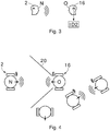
- the voice is initially any voice in the environment, but not the voice of the second user O. Accordingly, the voice that is picked up by the second hearing aid 16 is a foreign voice, ie either as in FIG Fig. 3 actually the voice of the first user N, provided that this is within range of the microphone 8, or another voice. It is essential that the second hearing aid 16 searches the surroundings for voices from other users N.
- an acoustic ID ID2 is expediently generated directly from it, for later use during coupling.
- this external ID ID2 is also stored in the memory 18.
- a respective hearing aid 2, 16 collects several foreign IDs ID2 over time, which then as in FIG Fig. 2 shown to be compared with a possibly received ID ID1.
- the in Fig. 3 In one possible embodiment, the step shown is part of the in Fig. 2 procedure shown.
- the result is that two different transmission channels are used to identify a user N.
- the first hearing aid 2 transmits an ID ID1 of the first user N via a signal path by the first ID ID1 is sent via the interface 14 as an electromagnetic signal to other hearing aids 16 in the vicinity.
- the second hearing aid 16 generates an ID ID2 of a user N over an air gap in that the voice of this user N is recorded as an acoustic signal with a microphone 8 and the second acoustic ID ID2 is then generated.
- the second hearing aid 16 finally compares the two IDs ID1, ID2, which were obtained from different transmission channels, in order to identify the first user N.
- the ID2 is stored in the memory 18 of the hearing aid 16 in an embodiment not explicitly shown. It is important, however, that the ID2 was generated from the voice of the first user N so that he can be identified accordingly.
- the voices of the users N, O are transmitted during the data exchange, so that a radio connection is established.
- a respective hearing aid 2, 16 picks up the voice of its own user N, O with its microphone 8.
- the microphone 8 generates a corresponding audio signal which, depending on the configuration, is additionally processed or not and is then transmitted to the other hearing aid 2, 16 via the interface 14.
- Fig. 1 not explicitly shown, but for example a transmission of the input signal E by means of the interface 14 is suitable.
- the other hearing aid 2, 16 receives the voice of the now other user N, O and converts it back into sound by means of the earpiece 12 for output to the own user N, O.
- the sending of the coupling request K1 with the first, own ID ID1 is in itself independent of the presence of the second and generally another user O. In the present case, however, the coupling request K1 is only sent out when the first hearing aid 2 detects that a second hearing aid 16 is within reach. To this end, the first hearing device 2 sends the first acoustic ID ID1 off when the first hearing aid 2 detects a conversation.
- a conversation situation is understood to mean that at least two users N, O, for example as in FIG Fig. 3 shown speaking to one another, typically reciprocally. If the first hearing aid 2 detects the presence of another user O in the vicinity, this activates the inquiry mode and sends out the first, own ID ID1. This ensures that the first ID ID1 is only sent out when a potential coupling partner is actually present.
- a respective hearing aid 2, 16 is designed in the present case to recognize a foreign voice.
- the respective microphone 8 and the respective voice analysis unit 6 are also used in the present case.
- the hearing aid 2, 16 picks up sound from the environment, generates an input signal E therefrom and feeds this to the voice analysis unit 6.
- This recognizes whether a strange voice is present in the environment or not.
- a voice is first extracted from the sound and an acoustic ID ID2 is generated from this.
- This is then compared, for example, with the acoustic ID ID1 of the user N assigned to the hearing aid 2, i.e. the user's own ID.
- the own ID is stored, for example, in the memory 18 of the hearing device 2 or is generated by the latter, for example likewise with the voice analysis unit 6.
- the conversation situation may be restricted to a subset of users N, O in the vicinity.
- the second hearing aid 16 picks up a voice for the second acoustic ID ID2 only from a sub-area 20 of the surroundings, namely from a sub-area 20 in which a conversation partner of the second user O is potentially staying.
- This sub-area 20 is in Fig. 4 a space quarter at the front with respect to the second user O.
- the sub-area 20 is a Directional lobe of a beamformer of the hearing aid 16. Overall, the coupling of the hearing aids 2, 16 is therefore direction-dependent.
- Fig. 5 is analogous to the representation in Fig. 2 a variant is shown in which the same steps are also carried out in reverse for the coupling in order to identify the second user O in an analogous manner.
- the coupling acceptance K2 of the second hearing aid 16 contains a coupling request K3 to the first hearing aid 2 for this purpose.
- This coupling request K3 comprises a separate acoustic ID ID3 of the second user O, which - analogously to the first ID ID1 - is received by the first hearing aid 2 and - analogous to the second ID ID2 - is compared with a stored external acoustic ID ID4.
- the remarks on Fig. 3 can be used in reverse, so that the ID4 is generated by the first hearing aid 2 from the voice of the user O analogously.
- the hearing aids 2, 16 thus perform a mutual comparison of the IDs ID1, ID3 of the two users N, O overall.
- the first hearing aid 2 then also sends a coupling acceptance K4 to the second hearing aid 16 if the acoustic ID ID3 of the second user 2 matches the stored acoustic ID ID4.
- the stored acoustic ID ID4 is generated with the voice analysis unit 6 from sound from the environment, as has already been described above.
- the embodiment according to Fig. 2 is used, for example, in a situation in which two users N, O each with a hearing aid 2, 16 approach one another and begin to talk to one another.
- the first hearing aid 2 recognizes by means of the microphone 8 that another user O is present in the vicinity and is also speaking.
- This first hearing aid 2 therefore transmits the acoustic ID ID1 of its own user N.
- This first ID ID1 is received by the second hearing aid 16 via its interface 14.
- the second hearing aid 16 now for its part picks up sound from the environment by means of its microphone 8 and extracts the voice of the first user N.
- An acoustic ID ID2 is generated from this voice, which in the described constellation is an ID of the first user N just like the first acoustic ID ID1 .
- the second hearing aid 16 When comparing the two IDs ID1, ID2, ie the self-generated ID ID2 on the one hand and the received ID ID1 on the other hand, the second hearing aid 16 now determines that the IDs ID1, ID2 match and that the hearing aid 2 of the first user N is for coupling ready. In response to this determination, the second hearing aid 16 sends the coupling assumption K2 to the first hearing aid, with the reception of which by the first hearing aid 2 the coupling then takes place.
- the coupling is carried out as in Fig. 5 shown only after, conversely, the second hearing aid 16 has also sent a self-generated ID ID3 of the second user O to the first hearing aid 2 and this has been successfully compared by the first hearing aid 2 with an ID ID ID4 of the second user O generated by the latter.
- This ID ID4 is generated by the first hearing device 2, for example, in that the first hearing device 2 uses its microphone 8 in a manner analogous to the second hearing device 16 in FIG Fig. 2 Picks up sound from the environment and examines it for
- the respective acoustic ID ID1, ID2, ID3, ID4 is generated based on at least one voice parameter of a respective voice and is selected from a set of voice parameters, including: vocal tract frequency, volume, voice frequency, voice rise, also referred to as pitch, speed, frequency range , Breathing frequency, level of rest, of vowel and consonant changes.
- voice parameters including: vocal tract frequency, volume, voice frequency, voice rise, also referred to as pitch, speed, frequency range , Breathing frequency, level of rest, of vowel and consonant changes.
- voice parameters including: vocal tract frequency, volume, voice frequency, voice rise, also referred to as pitch, speed, frequency range , Breathing frequency, level of rest, of vowel and consonant changes.
- All of the mentioned voice parameters can be determined in a simple manner from the input signal E of the microphone 8 of the respective hearing aid 2, 16, for example by means of a level, frequency, spectral or time domain analysis, which are for example part of the control unit 4 of the respective hearing aid 2, 16 are. How the individual voice parameters are specifically determined is of subordinate importance.
- the first ID ID1, which is sent out by the first hearing device 2 as a coupling request K1, is stored in the memory 18 of the first hearing device 2, for example.
- the own acoustic ID ID3 of the second user O, which is sent out with the coupling request K3, is stored, for example, in the memory 18 of the second hearing aid 16.
- these IDs ID1, ID3 are determined in the context of a calibration method that is not explicitly shown and then stored.
- these two separate IDs ID1, ID3 are generated by the respective hearing aid 2, 16 by using this as an example in FIG Fig. 6 shown the own voice of the respective own user N, O picks up.
- the hearing aid 2, 16 also measures one or more voice parameters and then uses them to generate the ID ID1, ID3 of its own user N, O. This is shown in Fig. 6 also stored in the memory 18 of the hearing aid 2, 16 for later, renewed use, but this is only optional per se.
- the respective external acoustic ID ID1, ID2, ID3, ID4 is stored in a contact database 22 of the respective hearing aid 2, 16.
- the contact database 22 is thus a kind of telephone book and enables easier coupling in the event of repeated coupling of the users N, O.
- the acoustic ID ID2, ID4 then does not have to be generated again each time by means of the microphone 8 and the voice analysis unit 6, but rather the one in the IDs ID1, ID2, ID3, ID4 stored in the contact database 22 are compared directly with a received ID ID1, ID3 in order to identify a user O, N.
- the contact database 20 is part of the memory 18.
Landscapes
- Engineering & Computer Science (AREA)
- Health & Medical Sciences (AREA)
- Acoustics & Sound (AREA)
- Physics & Mathematics (AREA)
- Computer Networks & Wireless Communication (AREA)
- General Health & Medical Sciences (AREA)
- Otolaryngology (AREA)
- Signal Processing (AREA)
- Neurosurgery (AREA)
- Computer Vision & Pattern Recognition (AREA)
- Audiology, Speech & Language Pathology (AREA)
- Human Computer Interaction (AREA)
- Multimedia (AREA)
- Business, Economics & Management (AREA)
- Game Theory and Decision Science (AREA)
- Mobile Radio Communication Systems (AREA)
- Telephonic Communication Services (AREA)
- Telephone Function (AREA)
- Circuit For Audible Band Transducer (AREA)
Applications Claiming Priority (1)
| Application Number | Priority Date | Filing Date | Title |
|---|---|---|---|
| DE102019219510.5A DE102019219510B3 (de) | 2019-12-12 | 2019-12-12 | Verfahren, bei welchem zwei Hörgeräte miteinander gekoppelt werden, sowie Hörgerät |
Publications (3)
| Publication Number | Publication Date |
|---|---|
| EP3836139A1 true EP3836139A1 (fr) | 2021-06-16 |
| EP3836139C0 EP3836139C0 (fr) | 2023-06-07 |
| EP3836139B1 EP3836139B1 (fr) | 2023-06-07 |
Family
ID=73138749
Family Applications (1)
| Application Number | Title | Priority Date | Filing Date |
|---|---|---|---|
| EP20206003.4A Active EP3836139B1 (fr) | 2019-12-12 | 2020-11-05 | Procédé d'accouplement de deux appareils auditifs ainsi qu'appareil auditif |
Country Status (4)
| Country | Link |
|---|---|
| US (1) | US11425510B2 (fr) |
| EP (1) | EP3836139B1 (fr) |
| CN (1) | CN112995874B (fr) |
| DE (1) | DE102019219510B3 (fr) |
Families Citing this family (4)
| Publication number | Priority date | Publication date | Assignee | Title |
|---|---|---|---|---|
| DE102019219563A1 (de) * | 2019-12-13 | 2021-06-17 | Sivantos Pte. Ltd. | Verfahren zum Betrieb eines Hörgerätesystems und Hörgerätesystem |
| EP4160565A1 (fr) | 2021-09-29 | 2023-04-05 | GN Hearing A/S | Système de localisation d'un dispositif accessoire électronique |
| CN115240689B (zh) * | 2022-09-15 | 2022-12-02 | 深圳市水世界信息有限公司 | 目标声音确定方法、装置、计算机设备和介质 |
| WO2024075434A1 (fr) * | 2022-10-07 | 2024-04-11 | ソニーグループ株式会社 | Système de traitement d'informations, dispositif, procédé de traitement d'informations et programme |
Citations (3)
| Publication number | Priority date | Publication date | Assignee | Title |
|---|---|---|---|---|
| EP1643801A2 (fr) | 2004-09-30 | 2006-04-05 | Siemens Audiologische Technik GmbH | Utilisation d'un système de prothèse auditive avec au moins deux prothèses auditives |
| US20080057868A1 (en) * | 2006-09-05 | 2008-03-06 | Samsung Electronics Co.; Ltd | Auto pairing system and method for bluetooth network |
| EP3101919A1 (fr) | 2015-06-02 | 2016-12-07 | Oticon A/s | Système auditif pair à pair |
Family Cites Families (9)
| Publication number | Priority date | Publication date | Assignee | Title |
|---|---|---|---|---|
| CA2476364C (fr) * | 2004-07-30 | 2011-05-10 | Research In Motion Limited | Compatibilite d'une prothese auditive avec un dispositif de communications sans fil |
| RU2398356C2 (ru) * | 2008-10-31 | 2010-08-27 | Cамсунг Электроникс Ко., Лтд | Способ установления беспроводной линии связи и система для установления беспроводной связи |
| CN103650534A (zh) * | 2011-07-13 | 2014-03-19 | 峰力公司 | 用于从远程地点测试听力设备的方法和系统 |
| US9628514B2 (en) * | 2011-11-10 | 2017-04-18 | Skype | Device association using an audio signal |
| EP3202160B1 (fr) * | 2014-10-02 | 2018-04-18 | Sonova AG | Procédé de provisionner d'aide d'ecoute entre des utilisateurs dans un réseau ad hoc et système correspondant |
| DK3057340T3 (da) * | 2015-02-13 | 2019-08-19 | Oticon As | Partnermikrofonenhed og et høresystem, der omfatter en partnermikrofonenhed |
| US11218821B2 (en) | 2017-08-11 | 2022-01-04 | Sonova Ag | Method and system for fitting a hearing device |
| EP3517083B1 (fr) * | 2018-01-24 | 2021-12-01 | FalCom A/S | Système de protection auditive et procédé associé |
| EP3525487B1 (fr) * | 2018-02-09 | 2020-09-16 | Widex A/S | Canal de communication entre une télécommande et un dispositif d'assistance auditive |
-
2019
- 2019-12-12 DE DE102019219510.5A patent/DE102019219510B3/de not_active Expired - Fee Related
-
2020
- 2020-11-05 EP EP20206003.4A patent/EP3836139B1/fr active Active
- 2020-12-11 CN CN202011457094.7A patent/CN112995874B/zh active Active
- 2020-12-14 US US17/120,511 patent/US11425510B2/en active Active
Patent Citations (3)
| Publication number | Priority date | Publication date | Assignee | Title |
|---|---|---|---|---|
| EP1643801A2 (fr) | 2004-09-30 | 2006-04-05 | Siemens Audiologische Technik GmbH | Utilisation d'un système de prothèse auditive avec au moins deux prothèses auditives |
| US20080057868A1 (en) * | 2006-09-05 | 2008-03-06 | Samsung Electronics Co.; Ltd | Auto pairing system and method for bluetooth network |
| EP3101919A1 (fr) | 2015-06-02 | 2016-12-07 | Oticon A/s | Système auditif pair à pair |
Also Published As
| Publication number | Publication date |
|---|---|
| US11425510B2 (en) | 2022-08-23 |
| DE102019219510B3 (de) | 2020-12-17 |
| CN112995874B (zh) | 2023-03-07 |
| EP3836139C0 (fr) | 2023-06-07 |
| CN112995874A (zh) | 2021-06-18 |
| US20210185455A1 (en) | 2021-06-17 |
| EP3836139B1 (fr) | 2023-06-07 |
Similar Documents
| Publication | Publication Date | Title |
|---|---|---|
| EP3873108B1 (fr) | Système auditif pourvu d'au moins un instrument auditif porté dans ou sur l'oreille de l'utilisateur, ainsi que procédé de fonctionnement d'un tel système auditif | |
| EP3836139B1 (fr) | Procédé d'accouplement de deux appareils auditifs ainsi qu'appareil auditif | |
| EP3451705B1 (fr) | Procédé et dispositif de reconnaissance rapide de voix propre | |
| EP2603018B1 (fr) | Dispositif auditif avec détection d'activité de locuteur et procédé de fonctionnement d'un dispositif auditif | |
| DE102017214163B3 (de) | Verfahren zum Betrieb eines Hörgeräts und Hörgerät | |
| DE102019206743A1 (de) | Hörgeräte-System und Verfahren zur Verarbeitung von Audiosignalen | |
| DE102010012622B4 (de) | Binaurales Verfahren und binaurale Anordnung zur Sprachsteuerung von Hörgeräten | |
| EP3445067A1 (fr) | Procédé de fonctionnement d'un appareil de correction additive et appareil de correction additive | |
| EP3427498B1 (fr) | Procédé et appareil auditif pour detection de la voix propre sur la base d'un seuil individuel | |
| EP3840418A1 (fr) | Procédé d'ajustement d'un instrument auditif et système auditif associé | |
| EP3386215B1 (fr) | Procédé de fonctionnement d'un dispositif d'aide auditive et dispositif d'aide auditive | |
| DE102017200597B4 (de) | Verfahren zum Betrieb eines Hörsystems und Hörsystem | |
| EP3337187A1 (fr) | Procédé de fonctionnement d'un dispositif de correction auditive | |
| EP3693960B1 (fr) | Procédé de traitement individualisé du signal d'un signal audio d'un appareil auditif | |
| EP3585071A1 (fr) | Procédé de commande de la transmission de données entre au moins un appareil auditif et un périphérique d'un système d'appareil auditif ainsi qu'appareil auditif | |
| EP3926981A1 (fr) | Système auditif doté d'au moins un instrument auditif porté sur la tête de l'utilisateur, ainsi que mode de fonctionnement d'un tel système auditif | |
| WO2021144033A1 (fr) | Procédé de fonctionnement d'une prothèse auditive | |
| EP2200341A1 (fr) | Procédé de fonctionnement d'un appareil d'aide auditive et appareil d'aide auditive doté d'un dispositif de séparation de sources | |
| CH717566A2 (de) | Verfahren zum Erkennen eines Zustandes betreffend ein Hörgerät sowie Hörgerät zur Durchführung des Verfahrens. | |
| EP4187928A1 (fr) | Procédé de fonctionnement d'un instrument auditif | |
| DE102019203786A1 (de) | Hörgerätesystem | |
| DE102008046040A1 (de) | Verfahren zum Betrieb einer Hörvorrichtung mit Richtwirkung und zugehörige Hörvorrichtung | |
| EP1881738B1 (fr) | Procédé d'utilisation d'une prothèse auditive et assemblage avec une prothèse auditive | |
| DE102016207936A1 (de) | Verfahren zum Betrieb eines Hörgeräts | |
| EP4149121A1 (fr) | Procédé de fonctionnement d'un appareil auditif |
Legal Events
| Date | Code | Title | Description |
|---|---|---|---|
| PUAI | Public reference made under article 153(3) epc to a published international application that has entered the european phase |
Free format text: ORIGINAL CODE: 0009012 |
|
| STAA | Information on the status of an ep patent application or granted ep patent |
Free format text: STATUS: THE APPLICATION HAS BEEN PUBLISHED |
|
| AK | Designated contracting states |
Kind code of ref document: A1 Designated state(s): AL AT BE BG CH CY CZ DE DK EE ES FI FR GB GR HR HU IE IS IT LI LT LU LV MC MK MT NL NO PL PT RO RS SE SI SK SM TR |
|
| STAA | Information on the status of an ep patent application or granted ep patent |
Free format text: STATUS: REQUEST FOR EXAMINATION WAS MADE |
|
| 17P | Request for examination filed |
Effective date: 20210709 |
|
| RBV | Designated contracting states (corrected) |
Designated state(s): AL AT BE BG CH CY CZ DE DK EE ES FI FR GB GR HR HU IE IS IT LI LT LU LV MC MK MT NL NO PL PT RO RS SE SI SK SM TR |
|
| GRAP | Despatch of communication of intention to grant a patent |
Free format text: ORIGINAL CODE: EPIDOSNIGR1 |
|
| STAA | Information on the status of an ep patent application or granted ep patent |
Free format text: STATUS: GRANT OF PATENT IS INTENDED |
|
| RIC1 | Information provided on ipc code assigned before grant |
Ipc: H04R 25/00 20060101ALI20220824BHEP Ipc: G10L 17/02 20130101AFI20220824BHEP |
|
| INTG | Intention to grant announced |
Effective date: 20220915 |
|
| GRAS | Grant fee paid |
Free format text: ORIGINAL CODE: EPIDOSNIGR3 |
|
| GRAA | (expected) grant |
Free format text: ORIGINAL CODE: 0009210 |
|
| STAA | Information on the status of an ep patent application or granted ep patent |
Free format text: STATUS: THE PATENT HAS BEEN GRANTED |
|
| AK | Designated contracting states |
Kind code of ref document: B1 Designated state(s): AL AT BE BG CH CY CZ DE DK EE ES FI FR GB GR HR HU IE IS IT LI LT LU LV MC MK MT NL NO PL PT RO RS SE SI SK SM TR |
|
| REG | Reference to a national code |
Ref country code: GB Ref legal event code: FG4D Free format text: NOT ENGLISH |
|
| REG | Reference to a national code |
Ref country code: CH Ref legal event code: EP Ref country code: AT Ref legal event code: REF Ref document number: 1577395 Country of ref document: AT Kind code of ref document: T Effective date: 20230615 |
|
| REG | Reference to a national code |
Ref country code: DE Ref legal event code: R096 Ref document number: 502020003573 Country of ref document: DE |
|
| U01 | Request for unitary effect filed |
Effective date: 20230607 |
|
| U07 | Unitary effect registered |
Designated state(s): AT BE BG DE DK EE FI FR IT LT LU LV MT NL PT SE SI Effective date: 20230614 |
|
| REG | Reference to a national code |
Ref country code: LT Ref legal event code: MG9D |
|
| PG25 | Lapsed in a contracting state [announced via postgrant information from national office to epo] |
Ref country code: NO Free format text: LAPSE BECAUSE OF FAILURE TO SUBMIT A TRANSLATION OF THE DESCRIPTION OR TO PAY THE FEE WITHIN THE PRESCRIBED TIME-LIMIT Effective date: 20230907 Ref country code: ES Free format text: LAPSE BECAUSE OF FAILURE TO SUBMIT A TRANSLATION OF THE DESCRIPTION OR TO PAY THE FEE WITHIN THE PRESCRIBED TIME-LIMIT Effective date: 20230607 |
|
| PG25 | Lapsed in a contracting state [announced via postgrant information from national office to epo] |
Ref country code: RS Free format text: LAPSE BECAUSE OF FAILURE TO SUBMIT A TRANSLATION OF THE DESCRIPTION OR TO PAY THE FEE WITHIN THE PRESCRIBED TIME-LIMIT Effective date: 20230607 Ref country code: HR Free format text: LAPSE BECAUSE OF FAILURE TO SUBMIT A TRANSLATION OF THE DESCRIPTION OR TO PAY THE FEE WITHIN THE PRESCRIBED TIME-LIMIT Effective date: 20230607 Ref country code: GR Free format text: LAPSE BECAUSE OF FAILURE TO SUBMIT A TRANSLATION OF THE DESCRIPTION OR TO PAY THE FEE WITHIN THE PRESCRIBED TIME-LIMIT Effective date: 20230908 |
|
| U20 | Renewal fee for the european patent with unitary effect paid |
Year of fee payment: 4 Effective date: 20231116 |
|
| PG25 | Lapsed in a contracting state [announced via postgrant information from national office to epo] |
Ref country code: SK Free format text: LAPSE BECAUSE OF FAILURE TO SUBMIT A TRANSLATION OF THE DESCRIPTION OR TO PAY THE FEE WITHIN THE PRESCRIBED TIME-LIMIT Effective date: 20230607 |
|
| PG25 | Lapsed in a contracting state [announced via postgrant information from national office to epo] |
Ref country code: IS Free format text: LAPSE BECAUSE OF FAILURE TO SUBMIT A TRANSLATION OF THE DESCRIPTION OR TO PAY THE FEE WITHIN THE PRESCRIBED TIME-LIMIT Effective date: 20231007 |
|
| PG25 | Lapsed in a contracting state [announced via postgrant information from national office to epo] |
Ref country code: SM Free format text: LAPSE BECAUSE OF FAILURE TO SUBMIT A TRANSLATION OF THE DESCRIPTION OR TO PAY THE FEE WITHIN THE PRESCRIBED TIME-LIMIT Effective date: 20230607 Ref country code: SK Free format text: LAPSE BECAUSE OF FAILURE TO SUBMIT A TRANSLATION OF THE DESCRIPTION OR TO PAY THE FEE WITHIN THE PRESCRIBED TIME-LIMIT Effective date: 20230607 Ref country code: RO Free format text: LAPSE BECAUSE OF FAILURE TO SUBMIT A TRANSLATION OF THE DESCRIPTION OR TO PAY THE FEE WITHIN THE PRESCRIBED TIME-LIMIT Effective date: 20230607 Ref country code: IS Free format text: LAPSE BECAUSE OF FAILURE TO SUBMIT A TRANSLATION OF THE DESCRIPTION OR TO PAY THE FEE WITHIN THE PRESCRIBED TIME-LIMIT Effective date: 20231007 Ref country code: CZ Free format text: LAPSE BECAUSE OF FAILURE TO SUBMIT A TRANSLATION OF THE DESCRIPTION OR TO PAY THE FEE WITHIN THE PRESCRIBED TIME-LIMIT Effective date: 20230607 |
|
| PG25 | Lapsed in a contracting state [announced via postgrant information from national office to epo] |
Ref country code: PL Free format text: LAPSE BECAUSE OF FAILURE TO SUBMIT A TRANSLATION OF THE DESCRIPTION OR TO PAY THE FEE WITHIN THE PRESCRIBED TIME-LIMIT Effective date: 20230607 |
|
| REG | Reference to a national code |
Ref country code: DE Ref legal event code: R097 Ref document number: 502020003573 Country of ref document: DE |
|
| PLBE | No opposition filed within time limit |
Free format text: ORIGINAL CODE: 0009261 |
|
| STAA | Information on the status of an ep patent application or granted ep patent |
Free format text: STATUS: NO OPPOSITION FILED WITHIN TIME LIMIT |
|
| 26N | No opposition filed |
Effective date: 20240308 |
|
| PG25 | Lapsed in a contracting state [announced via postgrant information from national office to epo] |
Ref country code: MC Free format text: LAPSE BECAUSE OF FAILURE TO SUBMIT A TRANSLATION OF THE DESCRIPTION OR TO PAY THE FEE WITHIN THE PRESCRIBED TIME-LIMIT Effective date: 20230607 |
|
| PG25 | Lapsed in a contracting state [announced via postgrant information from national office to epo] |
Ref country code: MC Free format text: LAPSE BECAUSE OF FAILURE TO SUBMIT A TRANSLATION OF THE DESCRIPTION OR TO PAY THE FEE WITHIN THE PRESCRIBED TIME-LIMIT Effective date: 20230607 |
|
| REG | Reference to a national code |
Ref country code: IE Ref legal event code: MM4A |
|
| PG25 | Lapsed in a contracting state [announced via postgrant information from national office to epo] |
Ref country code: IE Free format text: LAPSE BECAUSE OF NON-PAYMENT OF DUE FEES Effective date: 20231105 |
|
| PG25 | Lapsed in a contracting state [announced via postgrant information from national office to epo] |
Ref country code: IE Free format text: LAPSE BECAUSE OF NON-PAYMENT OF DUE FEES Effective date: 20231105 |
|
| U20 | Renewal fee for the european patent with unitary effect paid |
Year of fee payment: 5 Effective date: 20241022 |
|
| PG25 | Lapsed in a contracting state [announced via postgrant information from national office to epo] |
Ref country code: CY Free format text: LAPSE BECAUSE OF FAILURE TO SUBMIT A TRANSLATION OF THE DESCRIPTION OR TO PAY THE FEE WITHIN THE PRESCRIBED TIME-LIMIT; INVALID AB INITIO Effective date: 20201105 |
|
| PG25 | Lapsed in a contracting state [announced via postgrant information from national office to epo] |
Ref country code: HU Free format text: LAPSE BECAUSE OF FAILURE TO SUBMIT A TRANSLATION OF THE DESCRIPTION OR TO PAY THE FEE WITHIN THE PRESCRIBED TIME-LIMIT; INVALID AB INITIO Effective date: 20201105 |
|
| U20 | Renewal fee for the european patent with unitary effect paid |
Year of fee payment: 6 Effective date: 20251022 |
|
| REG | Reference to a national code |
Ref country code: CH Ref legal event code: U11 Free format text: ST27 STATUS EVENT CODE: U-0-0-U10-U11 (AS PROVIDED BY THE NATIONAL OFFICE) Effective date: 20251201 |
|
| PG25 | Lapsed in a contracting state [announced via postgrant information from national office to epo] |
Ref country code: TR Free format text: LAPSE BECAUSE OF FAILURE TO SUBMIT A TRANSLATION OF THE DESCRIPTION OR TO PAY THE FEE WITHIN THE PRESCRIBED TIME-LIMIT Effective date: 20230607 |
|
| PGFP | Annual fee paid to national office [announced via postgrant information from national office to epo] |
Ref country code: GB Payment date: 20251023 Year of fee payment: 6 |
|
| PGFP | Annual fee paid to national office [announced via postgrant information from national office to epo] |
Ref country code: CH Payment date: 20251201 Year of fee payment: 6 |