EP3848533A1 - Machine de liaison - Google Patents
Machine de liaison Download PDFInfo
- Publication number
- EP3848533A1 EP3848533A1 EP19856826.3A EP19856826A EP3848533A1 EP 3848533 A1 EP3848533 A1 EP 3848533A1 EP 19856826 A EP19856826 A EP 19856826A EP 3848533 A1 EP3848533 A1 EP 3848533A1
- Authority
- EP
- European Patent Office
- Prior art keywords
- binding machine
- grips
- axis line
- operator
- pair
- Prior art date
- Legal status (The legal status is an assumption and is not a legal conclusion. Google has not performed a legal analysis and makes no representation as to the accuracy of the status listed.)
- Granted
Links
Images


Classifications
-
- E—FIXED CONSTRUCTIONS
- E04—BUILDING
- E04G—SCAFFOLDING; FORMS; SHUTTERING; BUILDING IMPLEMENTS OR AIDS, OR THEIR USE; HANDLING BUILDING MATERIALS ON THE SITE; REPAIRING, BREAKING-UP OR OTHER WORK ON EXISTING BUILDINGS
- E04G21/00—Preparing, conveying, or working-up building materials or building elements in situ; Other devices or measures for constructional work
- E04G21/12—Mounting of reinforcing inserts; Prestressing
- E04G21/122—Machines for joining reinforcing bars
- E04G21/123—Wire twisting tools
-
- B—PERFORMING OPERATIONS; TRANSPORTING
- B21—MECHANICAL METAL-WORKING WITHOUT ESSENTIALLY REMOVING MATERIAL; PUNCHING METAL
- B21F—WORKING OR PROCESSING OF METAL WIRE
- B21F15/00—Connecting wire to wire or other metallic material or objects; Connecting parts by means of wire
- B21F15/02—Connecting wire to wire or other metallic material or objects; Connecting parts by means of wire wire with wire
- B21F15/04—Connecting wire to wire or other metallic material or objects; Connecting parts by means of wire wire with wire without additional connecting elements or material, e.g. by twisting
-
- B—PERFORMING OPERATIONS; TRANSPORTING
- B25—HAND TOOLS; PORTABLE POWER-DRIVEN TOOLS; MANIPULATORS
- B25B—TOOLS OR BENCH DEVICES NOT OTHERWISE PROVIDED FOR, FOR FASTENING, CONNECTING, DISENGAGING, OR HOLDING
- B25B25/00—Implements for fastening, connecting or tensioning of wire or strip
-
- B—PERFORMING OPERATIONS; TRANSPORTING
- B65—CONVEYING; PACKING; STORING; HANDLING THIN OR FILAMENTARY MATERIAL
- B65B—MACHINES, APPARATUS OR DEVICES FOR, OR METHODS OF, PACKAGING ARTICLES OR MATERIALS; UNPACKING
- B65B13/00—Bundling articles
- B65B13/02—Applying and securing binding material around articles or groups of articles, e.g. using strings, wires, strips, bands or tapes
- B65B13/025—Hand-held tools
-
- B—PERFORMING OPERATIONS; TRANSPORTING
- B65—CONVEYING; PACKING; STORING; HANDLING THIN OR FILAMENTARY MATERIAL
- B65B—MACHINES, APPARATUS OR DEVICES FOR, OR METHODS OF, PACKAGING ARTICLES OR MATERIALS; UNPACKING
- B65B13/00—Bundling articles
- B65B13/18—Details of, or auxiliary devices used in, bundling machines or bundling tools
- B65B13/24—Securing ends of binding material
- B65B13/28—Securing ends of binding material by twisting
- B65B13/285—Hand tools
Definitions
- the present disclosure relates to a binding machine configured to bind a binding object such as a reinforcing bar and the like with a wire rod such as a wire.
- PTL 1 discloses a machine including an outer cylindrical casing, two fixing claws connected to a tip end of the outer cylindrical casing and configured to arrange a wire so as to surround a binding object such as a reinforcing bar, a twisting mechanism arranged in the outer cylindrical casing and configured to twist two leg portions of the wire, and a handle connected to a rear end of the outer cylindrical casing via a telescopic part capable of adjusting a length thereof.
- a machine since an entire length of the machine can be increased by extending the telescopic part, it is convenient to bind reinforcing bars and the like distant from an operator.
- a binding machine includes a first body part having a pair of grips that can be grasped by an operator, a second body part having a curl guide configured to curl a wire around a binding object and a twisting unit including a twisting shaft for twisting the curled wire, and a connecting part connecting the first body part and the second body part each other.
- the pair of grips are provided on respective both sides of an axis line of the connecting part or an extension line of the axis line, as seen from an operator-side when the operator grasps and operates the grips.
- the pair of grips is provided on respective both sides of the axis line of the connection part or the like, as seen from the operator-side, the operator can grasp the grips with both hands. Thereby, it is possible to reduce the burden on an arm, a shoulder and the like of the operator during a binding operation.
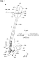
- FIG. 1 is a side view depicting an internal configuration of a reinforcing bar binding machine 1A of a first embodiment
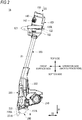
- FIG. 2 is a side view depicting an external configuration of the reinforcing bar binding machine 1A
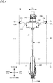
- FIG. 4 is a front view depicting the external configuration of the reinforcing bar binding machine 1A
- FIG. 5 is a rear view
- FIGS. 6 and 7 are perspective views
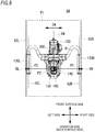
- FIG. 8 is a plan view.
- a reinforcing bar binding machine 1A includes a first body part 100 having a handle part 122 including a pair of grips 120R and 120L that can be grasped by an operator, a second body part 200 having a curl guide 230A configured to curl a wire W around a binding object and a twisting unit 250 configured to hold and twist the wire W curled by the curl guide 230A, and an elongated connecting part 300 configured to connect the first body part 100 and the second body part 200 each other.
- a side on which the curl guide 230A is provided is referred to a tip end-side or a bottom side of the reinforcing bar binding machine 1A, and an opposite side, i.e., an end portion-side of the first body part 100 is referred to as a base end-side or a top side of the reinforcing bar binding machine 1A.
- sides which are orthogonal to a vertical direction of the reinforcing bar binding machine 1A and on which the grips 120R and 120L are positioned are referred to as sides of the reinforcing bar binding machine 1A, and the grip 120R-side is referred to as a right side of the reinforcing bar binding machine 1A and the grip 120L-side is referred to as a left side of the reinforcing bar binding machine 1A.
- a side which is orthogonal to the vertical direction and the right and left direction of the reinforcing bar binding machine 1A and on which an operator who grasps the grips 120R and 120L stands is referred to as an operator-side or a back surface-side of the reinforcing bar binding machine 1A, and an opposite side is referred to as a front surface-side of the reinforcing bar binding machine 1A.
- the first body part 100 has a first housing 102, a handle part 122 attached to the first housing 102 and having the pair of grips 120R and 120L, and a battery mounting part 140 provided to the first housing 102 and configured to mount a battery 142.
- a tip end-side of the first housing 102 is connected to the connecting part 300, and a base end-side thereof is provided with a setting unit 150 for setting a variety of operation conditions of the reinforcing bar binding machine 1A.
- the handle part 122 is constituted by a U-shaped or M-shaped long member, as seen in an axis line direction D3 of the connecting part 300, and has the grips 120R and 120L on both ends thereof.
- a grip connecting part 121 is provided between the grips 120R and 120L and is attached to the first housing 102. At least one of the grips 120R and 120L is provided with an operation switch 160 (refer to FIG. 1 ) for starting a binding operation.
- the handle part 122 may have diverse shapes, such as a linear shape as seen in the axis line direction D3 of the connecting part 300 and a U-shape or M-shape as seen in the front surface or back surface direction.
- the grips 120R and 120L are provided on respective both sides of an axis line A3 of the connecting part 300 or an extension line of the axis line A3, as seen from the operator-side, when the operator grasps and operates the grips 120R and 120L.
- the grip 120R is arranged on the right side of the axis line A3, as seen from the operator-side, and the grip 120L is arranged on the left side of the axis line A3, as seen from the operator-side.
- the battery mounting part 140 is provided to the first housing 102 so as to be positioned above the handle part 122. As shown in FIGS. 2 , 4 and 8 , the battery mounting part 140 is also arranged between a pair of second virtual planes V2R and V2L each of which is tangent to each of outermost ends ER and EL in a width direction D4 of the pair of grips 120R and 120L (in an alignment direction of the pair of grips 120R and 120L) and is orthogonal to a first virtual plane V1 orthogonal to the twisting shaft 253. In the first embodiment, the battery mounting part 140 is arranged between the pair of grips 120R and 120L, as seen in the axis line direction D3 of the connecting part 300.
- a preferred arrangement position of the battery mounting part 140 is a position including an intermediate position P3 between a position P1 on an axis line A2R of the grip 120R and a position P2 on an axis line A2L of the grip 120L, as seen in the axis line direction D3, because the grips 120R and 120L are arranged at positions symmetrical with respect to the axis line A1 of the connecting part 300.
- the battery mounting part 140 may also be arranged on an extension line of the axis line A1 of the connecting part 300.
- the battery mounting part 140 when a gravity direction is set as a bottom side, the battery mounting part 140 is arranged above the grips 120R and 120L in a state where a tip end portion of the curl guide 230A is faced toward the gravity direction.
- the battery mounting part 140 has a mounting opening 141 on the front surface-side of the first housing 102 of the first body part 100, and is configured so that a battery 142 can be mounted in a direction orthogonal or substantially orthogonal to the axis line A1 of the connecting part 300.
- the mounting opening 141 may be provided on an upper surface-side of the first housing 102, and the battery mounting part 140 may be configured so that the battery can be mounted in the axis line direction D3 of the connecting part 300 or in substantially the axis line direction.
- the setting unit 150 is a unit for adjusting the number of turns of the wire W, the twisting torque for the wire W, and the like, and is constituted by a dial-type or push-type switch, for example.
- the second body part 200 has a second housing (housing) 202, a reel accommodation part 210 configured to accommodate a wire reel 211 on which the wire W is wound, a wire feeding unit 220 configured to reel out and feed the wire W from the wire reel 211 accommodated in the reel accommodation part 210, a curl guide 230A configured to curl the wire W around the binding object, a cutting unit (not shown) configured to cut the wire W curled by the curl guide 230A, and a twisting unit 250 configured to hold and twist the wire W curled by the curl guide 230A and cut by the cutting unit.
- the curl guide 230A is provided at a tip end portion of the second housing 202, and the wire feeding unit 220, the cutting unit and the twisting unit 250 are accommodated in the second housing 202.
- the wire feeding unit 220 is provided between the reel accommodation part 210 and the curl guide 230A, and has a pair of feeding gears for feeding the wire.
- the pair of feeding gears of the wire feeding unit 220 is configured to rotate in forward and reverse directions by drive of a motor (not shown). Thereby, when the feeding gears are rotated in the forward direction, the wire W can be fed toward the curl guide 230A, and when the feeding gears is rotated in the reverse direction, the wire W can be pulled back toward the reel accommodation part 210.
- the curl guide 230A has an opening 260 in which reinforcing bars S can be inserted, and is configured to curl the wire W around the reinforcing bars S inserted in the opening 260.
- the curl guide 230A is provided projecting further forward (in the first direction D1) from the tip end portion of the second housing 202, and is constituted by a pair of guide parts, i.e., a first guide part 231A and a second guide part 232A.
- the first guide part 231A and the second guide part 232A are arranged with a prescribed gap L to constitute the opening 260 in a second direction D2 orthogonal to the first direction D1.
- the first guide part 231A is configured to regulate an advancing direction of the wire W fed from the wire feeding unit 220 and to curl the wire W.
- the second guide part 232A is configured to receive the wire W curled by the first guide part 231A and to guide the wire to the twisting unit 250.
- the reinforcing bars S are inserted into the opening 260 between the first guide part 231A and the second guide part 232A.
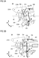
- a cover part 206 configured to cover a tip end-side end portion of the second housing 202 and a contact member 233 configured to move the second guide part 232A as the reinforcing bars S are contacted thereto are provided on a tip end-side of the second housing 202 and between the first guide part 231A and the second guide part 232A.
- the cover part 206 is constituted by a metal plate member, and is attached to cover an end portion on a bottom side of the second housing 202 between a base end-side of the first guide part 231A and a base end-side of the second guide part 232A.
- the contact member 233 is rotatably supported by a shaft 236 attached to the cover part 206.
- the contact member 233 is a dog leg-shaped member, and has a pair of contact parts 234 (only one contact part is shown in FIGS. 3A and the like) extending toward the first guide part 231A and a pressing part 235 extending toward the second guide part 232A with the shaft 236 being interposed therebetween.
- the contact parts 234 are arranged at positions at which the reinforcing bars S inserted in the opening 260 can contact, and the pressing part 235 is in contact with the second guide part 232A.
- the contact members 234 are pressed to the reinforcing bars S and are thus moved in an opposite direction to the first direction D1
- the contact member 233 rotates about the shaft 236 as a support point.
- the pressing part 235 pushes the second guide part 232A toward the first guide part 231A.
- the second guide part 232A moves from an open position opened with respect to the first guide part 231A to a closed position.
- the reinforcing bars S can be easily inserted into the opening 260 of the curl guide 230A.
- the reinforcing bar binding machine 1A having a long entire length like the first embodiment, since a binding position is distant from the operator, it is difficult to insert the reinforcing bars S. For this reason, when the second guide part 232A is open during the binding, the reinforcing bars S can be easily inserted into the opening 260 of the curl guide 230A.
- the twisting unit 250 includes a twisting motor 251, a deceleration mechanism 252 configured to perform deceleration and torque amplification of the twisting motor 251, a twisting shaft 253 connected to the deceleration mechanism 252 and configured to rotate by rotation of the twisting motor 251, a movable member 254 configured to be displaced by a rotating operation of the twisting shaft 253, and a holding part 255 projecting from a tip end-side of the movable member 254 and configured to hold and twist the wire W.
- An outer peripheral surface of the twisting shaft 253 and an inner peripheral surface of the movable member 254 are each formed with screws, so that the screw of the twisting shaft 253 is in mesh with the screw of the movable member 254.
- the holding part 255 has a plurality of claw portions for holding the wire W.
- the holding part 255 opens and closes as the movable member 254 moves in the front and rear direction, and rotates as the movable member 254 rotates.
- the connecting part 300 is an elongated hollow member and has a wiring laid therein.
- the connecting part 300 is constituted by a rod-shaped member thinner than diameters of the first body part 100 and the second body part 200.
- a length of the connecting part 300 is selected depending on an average height and the like of the operator, for example.
- metal such as aluminum and stainless steel and non-metal such as resin, carbon fiber and the like can be used. Thereby, it is possible to reduce an entire weight of the reinforcing bar binding machine 1A.
- a base end-side (upper end portion) of the connecting part 300 is attached to the first housing 102, and a tip end-side (lower end portion) of the connecting part 300 is attached to the second housing 202.
- the connecting part 300 can be configured so that it is detachably attached to the first body part 100 and the second body part 200.
- the wiring laid in the connecting part 300 is connected to the battery 142 and the operation switch 160 of the first body part 100 and a control device and the like of the second body part 200. Thereby, communication of electric signals can be performed between the first body part 100 and the second body part 200, and power can be supplied from the first body part 100 to the second body part 200.
- the operator When binding the reinforcing bars S, the operator inserts the reinforcing bars S into the opening 260 between the first guide part 231A and the second guide part 232A, and presses the reinforcing bars S to the contact parts 234 of the contact member 233. Accordingly, the contact member 233 rotates about the shaft 236 as a support point, so that the second guide part 232A is pushed by the pressing part 235 and is moved from the open position to the closed position. The operator turns on the operation switch 160 in a state where the second guide part 232A is closed, so that a binding operation starts.
- the pair of feeding gears of the wire feeding unit 220 rotates with sandwiching the wire W, thereby delivering the wire W from the wire reel 211 toward the curl guide 230A.
- the wire W fed by the wire feeding unit 220 is curled by the curl guide 230A, and the curled wire W is then wound several times around the reinforcing bars S.
- the number of winding times (number of turns) of the wire W around the reinforcing bars S can be set by the setting unit 150.
- the wire W wound several times on the reinforcing bars S is cut by the cutting unit and is then twisted by the twisting unit 250. By the above operations, the reinforcing bars S can be bound with the wire W.
- the grips 120R and 120L provided to the first body part 100 are positionally distant from the second body part 200, so that the center of gravity on the second body part 200-side of the reinforcing bar binding machine 1A also tends to be distant from the grips 120R and 120L. That is, the arrangement positions of the grips 120R and 120L do not coincide with the position of the center of gravity of the reinforcing bar binding machine 1A.
- the operator may perform an operation on the unstable reinforcing bars.
- the operator wants to bind the reinforcing bars without moving on the unstable reinforcing bars as much as possible. For this reason, the operator binds the reinforcing bars within the reach of the curl guide 230A while swinging the second body part 200 from front to back and from side to side, without changing a standing position.
- the second body part 200 is heavy, the burden on the arm, shoulder and the like of the operator increases.
- the pair of grips 120R and 120L is arranged on respective both sides of the axis line A1 and the like of the connecting part 300, as seen from the operator-side, the operator can grasp the grips 120R and 120L with both hands. Thereby, even when performing the operation while swinging the second body part 200 from front to back and from side to side without changing the standing position, the burden on the arm, shoulder and the like of the operator can be considerably reduced.
- the battery mounting part 140 is arranged between the pair of grips 120R and 120L, as seen in the axis line direction D3 of the connecting part 300, the battery 142 can be arranged in the vicinity of the operator.
- the battery 142 that is a heavy product can be arranged in the vicinity of an operation support point (rotation support point) of the operator, the operator can easily swing the reinforcing bar binding machine 1A from front to back and from side to side about the second body part 200-side of the reinforcing bar binding machine 1A as an operation support point. Thereby, the operability can be improved.
- the battery mounting part 140 is arranged on the axis line A1 of the connecting part 300, a weight balance is further improved.
- the battery 142 when the battery 142 is mounted, the battery 142 can be prevented from projecting from the first housing 102 toward the front surface-side. That is, when the second body part 200 is seen in the axis line direction D3 of the connecting part 300, the battery 142 can be made not to further project toward the front-surface side (outer side) than the curl guide 230A. Thereby, it is possible to secure the operator's visibility during the binding operation.
- the battery mounting part 140 is arranged above the grips 120R and 120L, the battery 142 can be easily attached and detached.
- the binding operation is enabled to start by turning on the operation switch 160.
- the present disclosure is not limited thereto.
- the binding operation may be enabled to start when it is detected that the reinforcing bars S are contacted to the contact member 233. In this case, the operability is improved because it is not necessary to turn on the operation switch 160 when binding the reinforcing bars S.
- the binding operation may be enabled to start when the reinforcing bars S are contacted to the contact member 233 in a state where the operation switch 160 is turned on.
- the reinforcing bars S can be bound in succession, so that the operability is improved.
- the binding operation does not start even though the reinforcing bars S are contacted to the contact member, so that a careless binding operation can be suppressed from being executed.
- an actuation switch that is switched between on and off states according to the rotating operation of the contact member 233 may be arranged in the vicinity of the contact member 233, and when the actuation switch becomes on, the binding operation may be executed.
- the actuation switch include a mechanical switch and a sensor such as a Hall IC.
- the operator When binding the reinforcing bars S, the operator inserts the reinforcing bars S into the opening 260 between the first guide part 231A and the second guide part 232A in a state where the operation switch 160 is turned on. Thereby, when the reinforcing bars S are pressed to the contact parts 234 of the contact member 233 and the contact member 233 rotates about the shaft 236 as a support point and moves to an operation position, for example, a second switch becomes on.
- a control unit (not shown) provided in the second body part 200 starts the binding operation when both the operation switch 160 and the actuation switch are on.
- the second guide part 232A is moved from the open position to the closed position by the rotation of the contact member 233.
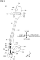
- FIG. 9 is a side view depicting an internal configuration of a reinforcing bar binding machine 1B of a second embodiment.
- the reinforcing bar binding machine 1B of the second embodiment is different from the reinforcing bar binding machine 1A of the first embodiment, in that the contact member 233 is not provided. Since the reinforcing bar binding machine 1B is not provided with the contact member 233, the curl guide 230B is not opened and closed even when the reinforcing bars S are inserted and pulled out with respect to the opening 260. Note that, the reinforcing bar binding machine 1B has a similar configuration to the reinforcing bar binding machine 1A, except that the contact member 233 is not provided.
- the technical scope of the present invention is not limited to the above embodiments, and includes a variety of changes made to the above embodiments without departing from the gist of the present invention.
- the battery mounting part 140 is not necessarily required to be provided on the axis line A1.
- the battery mounting part 140 may be provided on a virtual axis line A4, which includes the intermediate position P3 of the grips 120R and 120L and is parallel to each of the axis lines A2R and A2L of the grips 120R and 120L.
- the battery mounting part 140 may be provided at a position slightly deviating from the intermediate position P3.
- the battery mounting part 140 may also be arranged between the grips 120R and 120L and the connecting part 300.
- the space above the grips 120R and 120L can be omitted, so that it is possible to shorten the entire length of the reinforcing bar binding machine 1A and to improve the visibility.
Landscapes
- Engineering & Computer Science (AREA)
- Mechanical Engineering (AREA)
- Architecture (AREA)
- Civil Engineering (AREA)
- Structural Engineering (AREA)
- Basic Packing Technique (AREA)
- Hand Tools For Fitting Together And Separating, Or Other Hand Tools (AREA)
- Wire Processing (AREA)
Applications Claiming Priority (2)
| Application Number | Priority Date | Filing Date | Title |
|---|---|---|---|
| JP2018168251A JP7163679B2 (ja) | 2018-09-07 | 2018-09-07 | 結束機 |
| PCT/JP2019/035090 WO2020050386A1 (fr) | 2018-09-07 | 2019-09-05 | Machine de liaison |
Publications (4)
| Publication Number | Publication Date |
|---|---|
| EP3848533A1 true EP3848533A1 (fr) | 2021-07-14 |
| EP3848533A4 EP3848533A4 (fr) | 2022-05-04 |
| EP3848533C0 EP3848533C0 (fr) | 2024-08-21 |
| EP3848533B1 EP3848533B1 (fr) | 2024-08-21 |
Family
ID=69722886
Family Applications (1)
| Application Number | Title | Priority Date | Filing Date |
|---|---|---|---|
| EP19856826.3A Active EP3848533B1 (fr) | 2018-09-07 | 2019-09-05 | Machine de liaison |
Country Status (8)
| Country | Link |
|---|---|
| US (1) | US12060719B2 (fr) |
| EP (1) | EP3848533B1 (fr) |
| JP (1) | JP7163679B2 (fr) |
| CN (2) | CN120139507A (fr) |
| ES (1) | ES2988813T3 (fr) |
| PL (1) | PL3848533T3 (fr) |
| TW (1) | TWI842738B (fr) |
| WO (1) | WO2020050386A1 (fr) |
Families Citing this family (4)
| Publication number | Priority date | Publication date | Assignee | Title |
|---|---|---|---|---|
| WO2020050388A1 (fr) | 2018-09-07 | 2020-03-12 | マックス株式会社 | Machine de liaison |
| JP7275506B2 (ja) | 2018-09-07 | 2023-05-18 | マックス株式会社 | 結束機 |
| JP7354687B2 (ja) | 2018-09-07 | 2023-10-03 | マックス株式会社 | 結束機 |
| JP7625883B2 (ja) | 2021-02-15 | 2025-02-04 | マックス株式会社 | 結束機 |
Family Cites Families (40)
| Publication number | Priority date | Publication date | Assignee | Title |
|---|---|---|---|---|
| US4354535A (en) * | 1980-04-21 | 1982-10-19 | Powell Robert Y | Hand-held automatic wire binding tool |
| JP2530639B2 (ja) * | 1987-01-27 | 1996-09-04 | 松下電工株式会社 | 結束機 |
| SE9003176D0 (sv) * | 1990-10-04 | 1990-10-04 | Peter Hoyaukin | Saett och maskin foer sammanbindning av korsande staenger |
| JP3393684B2 (ja) * | 1993-08-16 | 2003-04-07 | 株式会社エスディーコーポレーション | 物品の結束方法及び結束装置 |
| JPH07290177A (ja) * | 1994-04-22 | 1995-11-07 | Toyota Kihan:Kk | 鉄筋結束機 |
| DE69530587T2 (de) | 1994-06-24 | 2004-03-25 | Talon Industries, LLC, Vail | Kabelbindewerkzeug mit antriebsmechanismus |
| JP2949703B2 (ja) * | 1995-06-30 | 1999-09-20 | マックス株式会社 | 鉄筋結束機における安全装置 |
| SE504740C2 (sv) * | 1995-08-18 | 1997-04-14 | Peter Hoyaukin | Maskin för sammanbindning av långsträckta föremål |
| GB0022557D0 (en) * | 2000-09-14 | 2000-11-01 | Black & Decker Inc | String trimmer |
| US20040229195A1 (en) | 2003-03-18 | 2004-11-18 | Leapfrog Enterprises, Inc. | Scanning apparatus |
| SE0302276L (sv) * | 2003-03-18 | 2004-04-06 | Peter Hoyaukin | Sätt och maskin för sammanbindning av långsträckta föremål |
| US7290570B1 (en) * | 2003-04-21 | 2007-11-06 | Spikes Larry W | Twist attachment device |
| US20060066591A1 (en) | 2004-03-17 | 2006-03-30 | James Marggraff | Method and system for implementing a user interface for a device through recognized text and bounded areas |
| US20060077184A1 (en) | 2004-03-17 | 2006-04-13 | James Marggraff | Methods and devices for retrieving and using information stored as a pattern on a surface |
| US20060033725A1 (en) | 2004-06-03 | 2006-02-16 | Leapfrog Enterprises, Inc. | User created interactive interface |
| US20060127872A1 (en) | 2004-03-17 | 2006-06-15 | James Marggraff | Method and device for associating a user writing with a user-writable element |
| US7453447B2 (en) | 2004-03-17 | 2008-11-18 | Leapfrog Enterprises, Inc. | Interactive apparatus with recording and playback capability usable with encoded writing medium |
| US7831933B2 (en) | 2004-03-17 | 2010-11-09 | Leapfrog Enterprises, Inc. | Method and system for implementing a user interface for a device employing written graphical elements |
| US20060078866A1 (en) | 2004-03-17 | 2006-04-13 | James Marggraff | System and method for identifying termination of data entry |
| US20060125805A1 (en) | 2004-03-17 | 2006-06-15 | James Marggraff | Method and system for conducting a transaction using recognized text |
| US7853193B2 (en) | 2004-03-17 | 2010-12-14 | Leapfrog Enterprises, Inc. | Method and device for audibly instructing a user to interact with a function |
| US20060067576A1 (en) | 2004-03-17 | 2006-03-30 | James Marggraff | Providing a user interface having interactive elements on a writable surface |
| US7347276B2 (en) * | 2004-08-23 | 2008-03-25 | Tci97 Inc. | Adjustable garden tool |
| US7069962B2 (en) * | 2004-08-27 | 2006-07-04 | Dara Cheng | Wire cutting and twisting tool with spool assembly and manual wire feeding mechanism |
| EP1951973B1 (fr) | 2005-10-10 | 2014-12-10 | Tymatic Ltd. | Appareil pour la liaison d'objets |
| US20090145271A1 (en) * | 2006-06-26 | 2009-06-11 | Par Martinsson | Handle member |
| GB0621428D0 (en) * | 2006-10-27 | 2006-12-06 | Tymatic Ltd | Consumables authentication |
| US9591809B2 (en) * | 2007-02-06 | 2017-03-14 | Mtd Products Inc | Split power tool |
| CN101353088B (zh) | 2008-06-20 | 2010-07-28 | 蔡昌开 | 钢筋捆扎机 |
| DE102010015218A1 (de) | 2010-04-16 | 2011-10-20 | Wacker Neuson Se | Drahtbindegerät mit Positioniereinrichtung |
| US11267038B2 (en) | 2015-07-22 | 2022-03-08 | Max Co., Ltd. | Binding machine |
| JP6632883B2 (ja) * | 2015-12-25 | 2020-01-22 | 株式会社マキタ | 電動作業機 |
| JP2017189822A (ja) | 2016-04-11 | 2017-10-19 | 株式会社マルイ | 手持ち電動工具及びアタッチメント付き電動結束機並びに延長用アタッチメント |
| JP6972553B2 (ja) * | 2016-12-29 | 2021-11-24 | マックス株式会社 | 結束機 |
| DE112017006047T5 (de) | 2017-01-10 | 2019-09-12 | Makita Corporation | Bindewerkzeug |
| JP6953159B2 (ja) | 2017-03-29 | 2021-10-27 | バンドー化学株式会社 | ポリオレフィン樹脂フィルム及び積層体 |
| US10688647B2 (en) * | 2017-05-19 | 2020-06-23 | The Toro Company | Lawn and garden tool with boom having adjustable length and detachable boom sections |
| US11365552B2 (en) * | 2017-06-07 | 2022-06-21 | Max Co., Ltd. | Binding machine |
| TWM552524U (zh) * | 2017-08-30 | 2017-12-01 | 大葉大學 | 立蹲兩用鋼筋綁紮機 |
| CN207314873U (zh) | 2017-10-17 | 2018-05-04 | 黑龙江省睿智方圆建筑工程有限公司 | 一种建筑钢筋快速捆扎机 |
-
2018
- 2018-09-07 JP JP2018168251A patent/JP7163679B2/ja active Active
-
2019
- 2019-09-05 US US17/273,337 patent/US12060719B2/en active Active
- 2019-09-05 EP EP19856826.3A patent/EP3848533B1/fr active Active
- 2019-09-05 CN CN202510410389.5A patent/CN120139507A/zh active Pending
- 2019-09-05 PL PL19856826.3T patent/PL3848533T3/pl unknown
- 2019-09-05 ES ES19856826T patent/ES2988813T3/es active Active
- 2019-09-05 WO PCT/JP2019/035090 patent/WO2020050386A1/fr not_active Ceased
- 2019-09-05 CN CN201980057822.4A patent/CN112654757A/zh active Pending
- 2019-09-06 TW TW108132295A patent/TWI842738B/zh active
Also Published As
| Publication number | Publication date |
|---|---|
| PL3848533T3 (pl) | 2025-01-13 |
| JP7163679B2 (ja) | 2022-11-01 |
| JP2020041299A (ja) | 2020-03-19 |
| CN120139507A (zh) | 2025-06-13 |
| EP3848533C0 (fr) | 2024-08-21 |
| TWI842738B (zh) | 2024-05-21 |
| CN112654757A (zh) | 2021-04-13 |
| ES2988813T3 (es) | 2024-11-21 |
| WO2020050386A1 (fr) | 2020-03-12 |
| US20210340781A1 (en) | 2021-11-04 |
| US12060719B2 (en) | 2024-08-13 |
| EP3848533A4 (fr) | 2022-05-04 |
| TW202019770A (zh) | 2020-06-01 |
| EP3848533B1 (fr) | 2024-08-21 |
Similar Documents
| Publication | Publication Date | Title |
|---|---|---|
| EP3848533B1 (fr) | Machine de liaison | |
| US11781328B2 (en) | Binding machine | |
| JP7201036B2 (ja) | 結束機 | |
| US12122544B2 (en) | Binding machine | |
| JP7310873B2 (ja) | 結束機 | |
| US11878823B2 (en) | Binding machine | |
| EP3342955B1 (fr) | Machine de liaison | |
| US11795710B2 (en) | Binding machine | |
| CN110155402B (zh) | 打捆机 | |
| JP7326997B2 (ja) | 結束機 | |
| US20240208683A1 (en) | Binding machine |
Legal Events
| Date | Code | Title | Description |
|---|---|---|---|
| STAA | Information on the status of an ep patent application or granted ep patent |
Free format text: STATUS: THE INTERNATIONAL PUBLICATION HAS BEEN MADE |
|
| PUAI | Public reference made under article 153(3) epc to a published international application that has entered the european phase |
Free format text: ORIGINAL CODE: 0009012 |
|
| STAA | Information on the status of an ep patent application or granted ep patent |
Free format text: STATUS: REQUEST FOR EXAMINATION WAS MADE |
|
| 17P | Request for examination filed |
Effective date: 20210304 |
|
| AK | Designated contracting states |
Kind code of ref document: A1 Designated state(s): AL AT BE BG CH CY CZ DE DK EE ES FI FR GB GR HR HU IE IS IT LI LT LU LV MC MK MT NL NO PL PT RO RS SE SI SK SM TR |
|
| DAV | Request for validation of the european patent (deleted) | ||
| DAX | Request for extension of the european patent (deleted) | ||
| A4 | Supplementary search report drawn up and despatched |
Effective date: 20220407 |
|
| RIC1 | Information provided on ipc code assigned before grant |
Ipc: B25B 25/00 20060101ALI20220401BHEP Ipc: B21F 15/06 20060101ALI20220401BHEP Ipc: E04G 21/12 20060101AFI20220401BHEP |
|
| RIN1 | Information on inventor provided before grant (corrected) |
Inventor name: SUGIHARA, SHINPEI Inventor name: TASHIMA, NOBUTAKA Inventor name: MORIJIRI, TAKESHI |
|
| STAA | Information on the status of an ep patent application or granted ep patent |
Free format text: STATUS: EXAMINATION IS IN PROGRESS |
|
| 17Q | First examination report despatched |
Effective date: 20230216 |
|
| GRAP | Despatch of communication of intention to grant a patent |
Free format text: ORIGINAL CODE: EPIDOSNIGR1 |
|
| STAA | Information on the status of an ep patent application or granted ep patent |
Free format text: STATUS: GRANT OF PATENT IS INTENDED |
|
| INTG | Intention to grant announced |
Effective date: 20240315 |
|
| GRAS | Grant fee paid |
Free format text: ORIGINAL CODE: EPIDOSNIGR3 |
|
| GRAA | (expected) grant |
Free format text: ORIGINAL CODE: 0009210 |
|
| STAA | Information on the status of an ep patent application or granted ep patent |
Free format text: STATUS: THE PATENT HAS BEEN GRANTED |
|
| AK | Designated contracting states |
Kind code of ref document: B1 Designated state(s): AL AT BE BG CH CY CZ DE DK EE ES FI FR GB GR HR HU IE IS IT LI LT LU LV MC MK MT NL NO PL PT RO RS SE SI SK SM TR |
|
| REG | Reference to a national code |
Ref country code: GB Ref legal event code: FG4D |
|
| REG | Reference to a national code |
Ref country code: CH Ref legal event code: EP |
|
| REG | Reference to a national code |
Ref country code: DE Ref legal event code: R096 Ref document number: 602019057588 Country of ref document: DE |
|
| REG | Reference to a national code |
Ref country code: IE Ref legal event code: FG4D |
|
| U01 | Request for unitary effect filed |
Effective date: 20240905 |
|
| U07 | Unitary effect registered |
Designated state(s): AT BE BG DE DK EE FI FR IT LT LU LV MT NL PT RO SE SI Effective date: 20240923 |
|
| U20 | Renewal fee for the european patent with unitary effect paid |
Year of fee payment: 6 Effective date: 20241007 |
|
| REG | Reference to a national code |
Ref country code: ES Ref legal event code: FG2A Ref document number: 2988813 Country of ref document: ES Kind code of ref document: T3 Effective date: 20241121 |
|
| PG25 | Lapsed in a contracting state [announced via postgrant information from national office to epo] |
Ref country code: GR Free format text: LAPSE BECAUSE OF FAILURE TO SUBMIT A TRANSLATION OF THE DESCRIPTION OR TO PAY THE FEE WITHIN THE PRESCRIBED TIME-LIMIT Effective date: 20241122 |
|
| PG25 | Lapsed in a contracting state [announced via postgrant information from national office to epo] |
Ref country code: IS Free format text: LAPSE BECAUSE OF FAILURE TO SUBMIT A TRANSLATION OF THE DESCRIPTION OR TO PAY THE FEE WITHIN THE PRESCRIBED TIME-LIMIT Effective date: 20241221 |
|
| PG25 | Lapsed in a contracting state [announced via postgrant information from national office to epo] |
Ref country code: HR Free format text: LAPSE BECAUSE OF FAILURE TO SUBMIT A TRANSLATION OF THE DESCRIPTION OR TO PAY THE FEE WITHIN THE PRESCRIBED TIME-LIMIT Effective date: 20240821 |
|
| PG25 | Lapsed in a contracting state [announced via postgrant information from national office to epo] |
Ref country code: RS Free format text: LAPSE BECAUSE OF FAILURE TO SUBMIT A TRANSLATION OF THE DESCRIPTION OR TO PAY THE FEE WITHIN THE PRESCRIBED TIME-LIMIT Effective date: 20241121 |
|
| PG25 | Lapsed in a contracting state [announced via postgrant information from national office to epo] |
Ref country code: RS Free format text: LAPSE BECAUSE OF FAILURE TO SUBMIT A TRANSLATION OF THE DESCRIPTION OR TO PAY THE FEE WITHIN THE PRESCRIBED TIME-LIMIT Effective date: 20241121 Ref country code: IS Free format text: LAPSE BECAUSE OF FAILURE TO SUBMIT A TRANSLATION OF THE DESCRIPTION OR TO PAY THE FEE WITHIN THE PRESCRIBED TIME-LIMIT Effective date: 20241221 Ref country code: HR Free format text: LAPSE BECAUSE OF FAILURE TO SUBMIT A TRANSLATION OF THE DESCRIPTION OR TO PAY THE FEE WITHIN THE PRESCRIBED TIME-LIMIT Effective date: 20240821 Ref country code: GR Free format text: LAPSE BECAUSE OF FAILURE TO SUBMIT A TRANSLATION OF THE DESCRIPTION OR TO PAY THE FEE WITHIN THE PRESCRIBED TIME-LIMIT Effective date: 20241122 |
|
| PG25 | Lapsed in a contracting state [announced via postgrant information from national office to epo] |
Ref country code: SM Free format text: LAPSE BECAUSE OF FAILURE TO SUBMIT A TRANSLATION OF THE DESCRIPTION OR TO PAY THE FEE WITHIN THE PRESCRIBED TIME-LIMIT Effective date: 20240821 |
|
| PG25 | Lapsed in a contracting state [announced via postgrant information from national office to epo] |
Ref country code: CZ Free format text: LAPSE BECAUSE OF FAILURE TO SUBMIT A TRANSLATION OF THE DESCRIPTION OR TO PAY THE FEE WITHIN THE PRESCRIBED TIME-LIMIT Effective date: 20240821 |
|
| PG25 | Lapsed in a contracting state [announced via postgrant information from national office to epo] |
Ref country code: SK Free format text: LAPSE BECAUSE OF FAILURE TO SUBMIT A TRANSLATION OF THE DESCRIPTION OR TO PAY THE FEE WITHIN THE PRESCRIBED TIME-LIMIT Effective date: 20240821 |
|
| REG | Reference to a national code |
Ref country code: CH Ref legal event code: PL |
|
| PLBE | No opposition filed within time limit |
Free format text: ORIGINAL CODE: 0009261 |
|
| STAA | Information on the status of an ep patent application or granted ep patent |
Free format text: STATUS: NO OPPOSITION FILED WITHIN TIME LIMIT |
|
| PG25 | Lapsed in a contracting state [announced via postgrant information from national office to epo] |
Ref country code: MC Free format text: LAPSE BECAUSE OF FAILURE TO SUBMIT A TRANSLATION OF THE DESCRIPTION OR TO PAY THE FEE WITHIN THE PRESCRIBED TIME-LIMIT Effective date: 20240821 |
|
| PG25 | Lapsed in a contracting state [announced via postgrant information from national office to epo] |
Ref country code: CH Free format text: LAPSE BECAUSE OF NON-PAYMENT OF DUE FEES Effective date: 20240930 |
|
| PG25 | Lapsed in a contracting state [announced via postgrant information from national office to epo] |
Ref country code: IE Free format text: LAPSE BECAUSE OF NON-PAYMENT OF DUE FEES Effective date: 20240905 |
|
| 26N | No opposition filed |
Effective date: 20250522 |
|
| U20 | Renewal fee for the european patent with unitary effect paid |
Year of fee payment: 7 Effective date: 20250807 |
|
| PGFP | Annual fee paid to national office [announced via postgrant information from national office to epo] |
Ref country code: NO Payment date: 20250909 Year of fee payment: 7 |
|
| PGFP | Annual fee paid to national office [announced via postgrant information from national office to epo] |
Ref country code: PL Payment date: 20250729 Year of fee payment: 7 |
|
| PGFP | Annual fee paid to national office [announced via postgrant information from national office to epo] |
Ref country code: GB Payment date: 20250731 Year of fee payment: 7 |
|
| PG25 | Lapsed in a contracting state [announced via postgrant information from national office to epo] |
Ref country code: CY Free format text: LAPSE BECAUSE OF FAILURE TO SUBMIT A TRANSLATION OF THE DESCRIPTION OR TO PAY THE FEE WITHIN THE PRESCRIBED TIME-LIMIT; INVALID AB INITIO Effective date: 20190905 |
|
| PGFP | Annual fee paid to national office [announced via postgrant information from national office to epo] |
Ref country code: ES Payment date: 20251013 Year of fee payment: 7 |
|
| PG25 | Lapsed in a contracting state [announced via postgrant information from national office to epo] |
Ref country code: HU Free format text: LAPSE BECAUSE OF FAILURE TO SUBMIT A TRANSLATION OF THE DESCRIPTION OR TO PAY THE FEE WITHIN THE PRESCRIBED TIME-LIMIT; INVALID AB INITIO Effective date: 20190905 |
|
| U1N | Appointed representative for the unitary patent procedure changed after the registration of the unitary effect |
Representative=s name: MARKS & CLERK LLP; GB |