EP3851196B1 - Procédé et appareil de manipulation et/ou de détection de particules - Google Patents
Procédé et appareil de manipulation et/ou de détection de particules Download PDFInfo
- Publication number
- EP3851196B1 EP3851196B1 EP21161552.1A EP21161552A EP3851196B1 EP 3851196 B1 EP3851196 B1 EP 3851196B1 EP 21161552 A EP21161552 A EP 21161552A EP 3851196 B1 EP3851196 B1 EP 3851196B1
- Authority
- EP
- European Patent Office
- Prior art keywords
- block
- electrodes
- electrode
- row
- blocks
- Prior art date
- Legal status (The legal status is an assumption and is not a legal conclusion. Google has not performed a legal analysis and makes no representation as to the accuracy of the status listed.)
- Active
Links
Images






Classifications
-
- G—PHYSICS
- G01—MEASURING; TESTING
- G01N—INVESTIGATING OR ANALYSING MATERIALS BY DETERMINING THEIR CHEMICAL OR PHYSICAL PROPERTIES
- G01N27/00—Investigating or analysing materials by the use of electric, electrochemical, or magnetic means
- G01N27/26—Investigating or analysing materials by the use of electric, electrochemical, or magnetic means by investigating electrochemical variables; by using electrolysis or electrophoresis
- G01N27/416—Systems
- G01N27/447—Systems using electrophoresis
- G01N27/44756—Apparatus specially adapted therefor
-
- G—PHYSICS
- G01—MEASURING; TESTING
- G01N—INVESTIGATING OR ANALYSING MATERIALS BY DETERMINING THEIR CHEMICAL OR PHYSICAL PROPERTIES
- G01N27/00—Investigating or analysing materials by the use of electric, electrochemical, or magnetic means
- G01N27/26—Investigating or analysing materials by the use of electric, electrochemical, or magnetic means by investigating electrochemical variables; by using electrolysis or electrophoresis
- G01N27/403—Cells and electrode assemblies
-
- B—PERFORMING OPERATIONS; TRANSPORTING
- B03—SEPARATION OF SOLID MATERIALS USING LIQUIDS OR USING PNEUMATIC TABLES OR JIGS; MAGNETIC OR ELECTROSTATIC SEPARATION OF SOLID MATERIALS FROM SOLID MATERIALS OR FLUIDS; SEPARATION BY HIGH-VOLTAGE ELECTRIC FIELDS
- B03C—MAGNETIC OR ELECTROSTATIC SEPARATION OF SOLID MATERIALS FROM SOLID MATERIALS OR FLUIDS; SEPARATION BY HIGH-VOLTAGE ELECTRIC FIELDS
- B03C5/00—Separating dispersed particles from liquids by electrostatic effect
- B03C5/02—Separators
- B03C5/022—Non-uniform field separators
- B03C5/026—Non-uniform field separators using open-gradient differential dielectric separation, i.e. using electrodes of special shapes for non-uniform field creation, e.g. Fluid Integrated Circuit [FIC]
-
- B—PERFORMING OPERATIONS; TRANSPORTING
- B03—SEPARATION OF SOLID MATERIALS USING LIQUIDS OR USING PNEUMATIC TABLES OR JIGS; MAGNETIC OR ELECTROSTATIC SEPARATION OF SOLID MATERIALS FROM SOLID MATERIALS OR FLUIDS; SEPARATION BY HIGH-VOLTAGE ELECTRIC FIELDS
- B03C—MAGNETIC OR ELECTROSTATIC SEPARATION OF SOLID MATERIALS FROM SOLID MATERIALS OR FLUIDS; SEPARATION BY HIGH-VOLTAGE ELECTRIC FIELDS
- B03C5/00—Separating dispersed particles from liquids by electrostatic effect
- B03C5/02—Separators
-
- G—PHYSICS
- G01—MEASURING; TESTING
- G01N—INVESTIGATING OR ANALYSING MATERIALS BY DETERMINING THEIR CHEMICAL OR PHYSICAL PROPERTIES
- G01N15/00—Investigating characteristics of particles; Investigating permeability, pore-volume or surface-area of porous materials
- G01N15/10—Investigating individual particles
- G01N15/1031—Investigating individual particles by measuring electrical or magnetic effects
-
- G—PHYSICS
- G01—MEASURING; TESTING
- G01N—INVESTIGATING OR ANALYSING MATERIALS BY DETERMINING THEIR CHEMICAL OR PHYSICAL PROPERTIES
- G01N15/00—Investigating characteristics of particles; Investigating permeability, pore-volume or surface-area of porous materials
- G01N15/10—Investigating individual particles
- G01N15/14—Optical investigation techniques, e.g. flow cytometry
- G01N15/1456—Optical investigation techniques, e.g. flow cytometry without spatial resolution of the texture or inner structure of the particle, e.g. processing of pulse signals
- G01N15/1459—Optical investigation techniques, e.g. flow cytometry without spatial resolution of the texture or inner structure of the particle, e.g. processing of pulse signals the analysis being performed on a sample stream
-
- B—PERFORMING OPERATIONS; TRANSPORTING
- B03—SEPARATION OF SOLID MATERIALS USING LIQUIDS OR USING PNEUMATIC TABLES OR JIGS; MAGNETIC OR ELECTROSTATIC SEPARATION OF SOLID MATERIALS FROM SOLID MATERIALS OR FLUIDS; SEPARATION BY HIGH-VOLTAGE ELECTRIC FIELDS
- B03C—MAGNETIC OR ELECTROSTATIC SEPARATION OF SOLID MATERIALS FROM SOLID MATERIALS OR FLUIDS; SEPARATION BY HIGH-VOLTAGE ELECTRIC FIELDS
- B03C2201/00—Details of magnetic or electrostatic separation
- B03C2201/24—Details of magnetic or electrostatic separation for measuring or calculating of parameters, e.g. efficiency
Definitions
- the present invention relates to methods and apparatuses for the manipulation and/or detection of particles.
- the invention finds application principally in the implementation of biological protocols on individual cells.
- the patent No. PCT/WO 00/69565 in the name of G. Medoro describes an apparatus and a method for the manipulation of particles via the use of closed dielectrophoretic-potential cages.
- the method described teaches how to control the position of each particle independently of all the others in a two-dimensional space.
- the force used for entrapping the particles in suspension is negative dielectrophoresis.
- the individual control on the operations of manipulation is carried out by programming memory elements and circuits associated to each element of an array of electrodes integrated in one and the same substrate. There follows an important limitation due to the dimensions of each trap, limited by the need to integrate in the space corresponding to an individual electrode the electronics necessary for programming. Furthermore described in G.
- EWOD electro-wetting on dielectric
- EHD electro-hydrodynamic
- ETF electrothermal
- AC electro-osmosis AC electro-osmosis
- EHD flows are used to displace particles.
- the patent No. PCT WO 2004/071668 A1 describes an apparatus for concentrating particles on the electrodes, exploiting the aforesaid electro-hydrodynamic flows.
- the present invention enables independent manipulation of a multiplicity of particles in a two-dimensional space, with or without contact depending upon the forces used.
- the implementation of the method according to the invention does not require the use of electronic circuits or memory elements integrated in the substrate.
- Different embodiments of the method and apparatus according to the present invention enable manipulation of particles in an n ⁇ m two-dimensional array of arbitrary size, with a number of control signals of the order of n+m, or else n, or else even with less than ten control signals, reducing, according to different compromises, the parallelism and flexibility of movement of the particles, and consequently the number of steps to perform a series of displacements (a parameter that is obviously linked to the time of execution).
- the present invention teaches how to combine manipulation and detection by integrating said operations on the same substrate or interfacing sensors and actuators made on different substrates depending upon the technology used.
- the present invention relates to a method and apparatus for the manipulation of particles (in an extensive sense, as described hereinafter) by means of time-variable non-uniform fields of force, and/or for their detection.
- the fields of force can be of positive dielectrophoresis or negative dielectrophoresis, electrophoresis or any electro-hydrodynamic motion, characterized by a set of stable points of equilibrium for the particles (solid, liquid or gaseous).
- the same method is adaptable to the manipulation of droplets (liquid particles), exploiting effects known to the international scientific community under the name of "electrowetting on dielectric" (EWOD).
- the aim of the present invention is to act on control of the position of each particle present in the sample, for the purpose of displacing said particles independently of one another from an initial position to any element belonging to the set of the final positions in a given space within a microchamber of the device.
- each point of equilibrium in a homogeneous array of elements can contain a particle or a group of particles.
- Each of said points of equilibrium can be joined without distinction to any one of the adjacent points of equilibrium, allowing the entrapped particles to share the basin of attraction thereof.
- This control is made by acting exclusively on the signals shared by all the elements belonging to the same row or column, used for distributing the voltages necessary for generation of the forces.
- each path can be broken down into a succession of elementary steps constituted by the union of adjacent basins of attraction, thus allowing each particle to be guided from the initial position to a final destination.
- Forming the subject of the present invention are also some practical implementations of the method by means of apparatuses constituted by n+m+2 control signals and by n+2m+2 control signals for arrays of size n ⁇ m.
- control is made by acting exclusively on the digital signals used for controlling a deviator associated to each element of the array, through which to distribute the voltages necessary for generation of the forces.
- the object of the present invention is also an apparatus constituted by n+m digital signals for control of the distribution of the two voltages necessary for generation of the forces in an n ⁇ m array.
- the object of the present invention is moreover a device that advantageously makes available some of the aforesaid methods, constituted by an array of electrodes, applied to which are time-variant potentials, with or without transistors or memory elements.
- the object of the present invention is also a family of apparatuses for identification and/or quantification and/or characterization of particles by means of impedance meter and/or optical sensors.
- the combination of sensors and actuators is particularly useful for automation of complex operations but proves in any case advantageous for positioning the particles to be individuated exactly in the regions of greater sensitivity for the sensors (which may be integrated but also external), thus considerably improving the sensitivity of the measurement.
- particles will be used to indicate micrometric or nanometric entities, either natural ones or artificial ones, such as cells, subcellular components, viruses, liposomes, niosomes, microspheres, and nanospheres, or even smaller entities, such as macro-molecules, proteins, DNA, RNA, etc., as well as drops of liquid immiscible with the suspension medium, for example oil in water, or water in oil, or even drops of liquid in gas (such as water in air) or bubbles of gas in liquid (such as air in water).
- liquid immiscible with the suspension medium for example oil in water, or water in oil, or even drops of liquid in gas (such as water in air) or bubbles of gas in liquid (such as air in water).
- the aim of the present invention is the implementation of a method and an apparatus for the manipulation and/or detection of particles.
- manipulation is meant, in particular, one of the following operations and/or combinations thereof:
- the method is based upon the use of a non-uniform field of force (F) through which to attract individual particles or groups of particles towards positions of stable equilibrium (CAGE).
- Said field can, for example, be a dielectrophoresis field (DEP), either negative dielectrophoresis (NDEP) or positive dielectrophoresis (PDEP) field, an electrophoretic field (EF) or else a field of electrohydrodynamic (EHD) motion, or else again electro-wetting on dielectric (EWOD).
- DEP dielectrophoresis field
- NDEP negative dielectrophoresis
- PDEP positive dielectrophoresis
- EHD electrohydrodynamic
- EWOD electro-wetting on dielectric
- the detection can regard one of the following aspects or a combination thereof:
- the field generates a force that acts on the particles, attracted towards points of equilibrium (CAGE).
- CAGE points of equilibrium
- NDEP negative DEP
- the cover (LID) is a conductive electrode.
- the point of equilibrium (CAGE) is obtained at each electrode connected to Vphin (-) if the adjacent electrodes are connected to the opposite phase Vphip (+) and if the cover (LID) is connected to the phase Vphin (-).
- Said point of equilibrium (CAGE) is normally set in the liquid at a distance from the electrodes, so that the particles (BEAD) are, in the steady-state condition, in levitation.
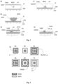
- the point of equilibrium (CAGE) is located normally at the surface on which the electrodes are formed ( Figure 1b ), and the particles (BEAD) are, in the steady-state condition, in contact therewith.
- the points of equilibrium of the PDEP correspond to the maxima of the electrical field.
- the negative dielectrophoresis (NDEPDR) can be advantageously used ( Figure 1c ) obtained by means of a substrate (SUB) with electrodes (EL), coated by a dielectric layer (D) and by a hydrophobic layer (HPB).
- An array of electrodes can be used for electrophoresis, to attract charged particles towards the electrodes with opposite polarity.
- the configurations of electrodes generate flows that push the particles towards points of minimum of the flow.
- a cover (LID) containing an electrode coated with dielectric is in general used, and the array of electrodes is energized by signals in phase opposition with respect to the cover in the points in which it is desired to attract the particles (typically droplets of liquid in air).
- the electrodes on which the particle must not be present are, instead, left floating.
- a series of wires Figure 1e
- a first electrode to be supplied by means of a signal (Vphin) in phase with the cover (LID) and one or more electrodes (L1) that surround completely the first electrode, supplied by means of a signal in phase opposition (Vphip).
- Vphin signal
- Vphip signal in phase opposition
- This configuration (illustrated in Figure 2a ) generates a minimum for the electrical field, corresponding to a point of stable equilibrium (CAGE) for the force of negative dielectrophoresis. Said point of equilibrium is lost if we reverse the phase of the signal applied to this first array of electrodes (L1), as illustrated in Figure 2b .
- the cage may have a dimension and shape that depends upon the voltages applied.
- Figure 2c and Figure 2d we have two identical cages whilst in Figure 2e we have one cage of larger dimensions, but centred in the same position.
- a homogeneous array of generic groups (BLOCK_i,j) of electrodes provide an array of attraction cages defined by points of stable equilibrium (CAGE_i,j), each of which can entrap a single particle (BEAD) or group of particles.
- the total number of row signals is designated by u, whilst the total number of column signals is designated by v.
- Vrow_i [p], Vcol_j [q] are used both for creation of the cages and for control of the position of the cages. Distributed through these signals are in fact the voltages necessary for the activation of the field of force of dielectrophoresis which have the following properties:
- the voltages to be used are generally but not exclusively periodic waves (either sinusoidal waves or else square waves) with zero mean value, chosen between a set of voltages having a different phase; by way of non-limiting example, it is possible to use just two phases, which differ by 180° from one another.
- a sample is injected with particles that set themselves randomly on the array.
- Said particles can be selected, for example, at the microscope, and, once the position of those of interest is determined, the problem is posed of sending them towards a gate (for example, communicating with a second recovery microchamber), from which they can be made to flow out of the chip.
- a gate for example, communicating with a second recovery microchamber
- a simple and efficient solution which does not require the knowledge of the position of all the particles but only of those to be selected, is the following (in the hypothesis that the gate is set on the right-hand side and at the bottom of the microchamber):
- Said method must be slightly complicated by preliminary operations in the case where the distance between columns of particles to be recovered is not always greater than 2, or in the case where there are, at the start of the procedure, particles on the routing row that have to be recovered.
- the description of said operations is omitted in so far as they are evident to a person with ordinary skill in the sector.
- the need for carrying out these preliminary operations is more unlikely if the number of particles to be recovered is negligible with respect to the number of columns.
- the number of steps to be taken for recovery of the particles is not significantly greater than the number of steps necessary with an array of totally programmable electrodes.
- the subject of the present invention is also an apparatus for obtaining the field configurations necessary for the manipulation of individual particles according to the method described previously.
- possible embodiments are provided, both based upon the use of a substrate without transistors and memory elements.
- FIGS 4 and 5 are, respectively, a cross-sectional view and a top plan view of a first embodiment of the apparatus according to the present invention.
- a homogeneous array of groups (BLOCK_i,j) of electrodes forms an array of size n ⁇ m.
- Each block (BLOCK_i,j) is constituted by a central electrode (EL_i,j) connected to a signal common to the entire array (Vcore) and two concentric electrodes (ring_i,j_1, ring_i,j_2) connected to two different voltages (Vrow_i, Vcol_j) distributed in the array, respectively, in rows and columns as illustrated in Figure 5 .
- a further signal (Vlid) is connected to the cover (LID), constituted by a single electrode (ITO) (illustrated only in Figure 4 ).
- an attraction cage (CAGE_i,j) is activated in each block (BLOCK_i,j) separated and distinct from all the others in the array.
- the particle (BEAD) entrapped in a generic block (BLOCK_i,j) can be displaced towards any one of the adjacent cages by means of an appropriate sequence of voltages applied to the control signals.
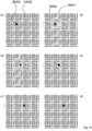
- Figure 7 shows the sequence of the steps (a, b, c, d, e) used to displace a particle from the generic block (BLOCK_i,j) into the adjacent block to the right (BLOCK_i,j+1); the voltages applied to the signals involved in the various steps that constitute said operation are indicated in Figure 10 (sequence move_x), whilst the position of the particle in transient conditions after each step is indicated in Figure 7 (b, c', d', e', a").
- Figure 8 shows the sequence of displacement of a particle in the vertical direction, from the generic block (BLOCK_i,j) into the adjacent block downwards (BLOCK_i+1,j).
- the voltages applied to the signals involved in the various steps that constitute said operation are indicated in Figure 10 (sequence move_y), whilst the position of the particle in steady-state conditions after each step is indicated in Figure 8 (b, c', d', e', a").
- a reduced sequence constituted by a subset of the steps chosen from the sequences shown in Figure 7 and Figure 8 .
- noble metals gold, platinum, etc.
- conductive oxides which are particularly useful in the case where said oxides are transparent (Indium Tin Oxide - ITO).
- substrate insulators glass, polycarbonate, etc.
- semiconductors silicon, etc.
- a passivation oxide is required for insulating the substrate electrically from the first metal level.
- cover an insulating substrate can be used provided that it is equipped with an electrode which also may be made with metals or conductive oxides, which are particularly useful in the case where said conductive oxides are partially or totally transparent.
- semitransparency can be obtained using a non-transparent metal in the form of a grid.
- Figure 11 is a top plan view of a different embodiment of the apparatus according to the present invention.
- four signals are used for each row and four signals for each column, plus a global signal Vcore common to all the blocks (distributed herein by column) and a signal Vlid.
- the external and internal ring electrodes of each block are divided into two, vertically and horizontally, respectively. Alternately connected to the electrodes of each block are just two of the four row signals, and just two of the four column signals.
- the row signals and column signals are normally all connected to Vphip, and generate a field configuration (F_i), with an attraction cage (CAGE_i,j), for each block.
- F_i field configuration
- CAGE_i,j attraction cage
- this embodiment presents the advantage of requiring only two field configurations for each elementary displacement, and the disadvantage of requiring a number of control signals four times greater.
- FIG. 13 is the top plan view of a further embodiment of the apparatus according to the present invention.
- a homogeneous array of blocks (BLOCK_i,j) forms an array of size n ⁇ m.
- Each block (BLOCK_i,j) is made up of: a central electrode (EL_i,j) connected to a signal common to the entire array (Vcore); an L-shaped electrode (elle_j) connected to signals distributed in the array according to columns (Venable_j); and two electrodes, one in the form of a vertical segment (wallx_i) and the other in the form of a horizontal segment (wally_i) connected to two different signals (Vrow_i[x], Vrow_i[y]) distributed in the array according to rows and arranged radially on the outside (with respect to the central electrode) of the electrode elle_j.
- a further signal (Vlid) is connected to the cover (LID), constituted by a single electrode (ITO).
- an attraction cage (CAGE_i,j) in each block (BLOCK_i,j) separate and distinct from all the others in the array is activated.
- the particle (BEAD) entrapped in each generic block (BLOCK_i,j) can be displaced towards any one of the adjacent cages by means of an appropriate sequence of voltages applied to the control signals.
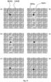
- Figure 14 shows the sequence of the steps (a, b, c, d) used to displace a particle from the generic block (BLOCK_i,j) into the adjacent block to the right (BLOCK_i,j+1); the voltages applied to the signals involved in the various steps of said operation are indicated in Figure 16 (sequence move_x), whilst the position of the particle in transient conditions after each step is indicated in Figure 14b' , c'.
- Figure 15 shows the sequence of the steps (a, b, c, d) used to displace a particle from the generic block (BLOCK_i,j) into the adjacent block downwards (BLOCK_i+1,j).
- noble metals gold, platinum, etc.
- conductive oxides which are particularly useful in the case where said oxides are transparent (Indium Tin Oxide - ITO).
- substrate insulators glass, polycarbonate, etc.
- semiconductors silicon, etc.
- a further embodiment of the method according to the present invention uses an array of attraction cages (CAGE_i,j), in which each block (BLOCK_i,j) is electrically connected to two groups of signals (Vrow_i[p], Vcol_j[q]) distributed in the array, respectively, in rows and columns. Some of these signals are used for the distribution of the voltages (Vphin, Vphip) necessary for creation of the cages (CAGE), whilst others are digital signals used for control of the phase to be applied to the electrodes.
- the position of the points of static equilibrium (CAGE_i,j) is controlled by means of electronic circuits, which determine for each block whether the attraction cage is in isolation or connected to adjacent cages.
- the subject of the present invention is also an apparatus for the production of the field configurations necessary for the manipulation of individual particles according to the method described previously.
- a possible embodiment is shown based upon the use of active substrates, in which, however, each block is without memory elements, unlike what is reported in the known art.
- FIG. 18 is a top plan view of a possible embodiment of the apparatus according to the present invention.
- a further signal (Vlid) is connected to the cover (LID), not shown, constituted by a single electrode (ITO).
- an attraction cage (CAGE_i,j) is activated in each block (BLOCK_i,j) separate and distinct from all the other in the array.
- the particle (BEAD) entrapped in each generic block (BLOCK_i,j) can be displaced towards any of the adjacent cages by means of an appropriate sequence of logic values applied to the control signals.
- Figure 19 shows the sequence of the steps (a, b, c,) used to displace a particle from the generic block (BLOCK_i,j) into the adjacent block to the right (BLOCK_i, j+1); the sequence of the logic values applied to the signals row i, col j and col j+1 is the following: (a) (b) (c) (a') col j 0 1 0 0 col j+1 0 1 1 0 row i 0 1 1 0
- any path that starts from a generic position in the array and terminates in any other position of the array can be broken down into the succession of the elementary steps constituted by displacements of just one position.
- the implementation of the apparatus according to the present invention can be obtained exploiting different technologies of fabrication of microelectronic circuits according to the known art.
- a further embodiment of the method is illustrated schematically in Figure 20 .
- the method uses a set of points of stable equilibrium that are static for the force (F) that acts on the particles, located within blocks (BLOCK_i,j), the function of which is that of entrapping stably a particle, and a set of points of stable equilibrium moving along lanes in the horizontal direction (HRCH1-HRCHM) or vertical direction (VRCH1-VRCHN).
- Each of these blocks (BLOCK_i,j) can be configured for entrapping the particle or pushing it within the basin of attraction of one of the points of stable equilibrium moving along the lanes.
- each of the particles present in the sample can consequently be parked within the blocks or else can be displaced from one block to any other one exploiting one or more lanes, in the most convenient direction.
- the particle can, in fact, enter a lane in motion and, likewise, the particle can exit from these lanes to enter a new block, or to change the direction of motion, passing onto a new lane. It is evident to persons with ordinary skill in the sector that each particle can pass from one block to any other one exploiting the method according to the present invention.
- Figure 21 shows a second embodiment of the method with a reduced number of horizontal paths. It is evident that also in this case each particle can pass from one block to any other one exploiting the single horizontal path (HRCH1).
- HRCH1 single horizontal path
- Figure 22 shows a possible application of the method.
- Present inside a microchamber (CHW) is an array of blocks (BLOCK_i,j) the function of which is the one described previously.
- the microchamber splits the array into two parts: one part (MCH) provided for containment of the sample to be processed, the other (RCH) provided for containment of the processed sample.
- MCH one part
- RH the other
- this scheme could be used for selecting just one particle retained in the first microchamber ((MCH) and recover it from the second microchamber (RCH).
- Each block (BLOCK_i,j) is functionally connected to a vertical corridor (VRCHJ), the direction and sense of movement of which is coherent within the entire array and terminates with a single horizontal corridor (HRCH1), the direction and sense of movement of which is chosen so that the particles conveyed can be transferred from the first microchamber (MCH) to the second microchamber (RCH) and then be accumulated in a single area through a final corridor (VRCHR).
- the selection of a particle from among the n ⁇ m retained initially in the first microchamber can be made, for example, by transferring it onto the corresponding lane and conveying it into the second microchamber (RCH), initially free from particles, from which the particle selected can be extracted.
- the subject of the present invention is also an apparatus for the production of the field configurations necessary for the manipulation of particles according to the method described previously, e.g., based upon the use of parking blocks and lanes.
- a possible embodiment is shown based upon the use of passive substrates, in which each block is without any memory elements or transistors.
- FIG. 23 is a top plan view of a first embodiment of the apparatus according to the present invention.
- a homogeneous array of blocks forms an array of attraction cages capable of entrapping a particle stably.
- Each block (BLOCK_i,j) is made up of: a central electrode, connected to a control signal (Vcage_j) common to all the blocks of the same column (or even to the entire array); a set of electrodes connected to a signal (Vpj) common to the entire array, and corresponding to Vphip; an electrode connected to a control signal (Vcol_j) common to all the blocks of the same column; and, finally, an electrode connected to a control signal (Vrow_i) common to all the blocks of the same row.
- each corridor is made up of an array of electrodes connected to signals common to the entire corridor (V1_j, V2_j and V3_j).
- the apparatus can have available one or more corridors oriented in a horizontal direction (HRCH), controlled by three signals common to the entire corridor (Vh_1, Vh_2 and Vh_3), operation of which is altogether similar to that of the corridors oriented vertically (VRCHJ).
- Figure 25 shows the voltages applied to the signals involved in the various steps that constitute the sequence for exit from a block (CHACCIJ), for shifting by a position along the vertical corridor (CONVEYV), for entry into the horizontal corridor (HCHACC), and for running along the horizontal corridor (CONVEYH). It is evident that in order to reverse the sense of travel along the horizontal corridor or vertical corridor it is sufficient to reverse the sequence of the phases with respect to that illustrated in Figure 25 .
- Figure 24 shows the top plan view of a further embodiment of the apparatus for the manipulation with lanes and parking cells. Operation is altogether similar to that of the embodiment described previously, but enables a greater density of attraction cages to be obtained per unit surface in so far as, for each column of blocks BLOCK_ij, the n electrodes at potential Vpj are replaced by a single comb-shaped electrode at potential Vpj.
- the number of control signals for both of the implementations without transistors of the apparatus with lanes and parking cells, for an array of n ⁇ m blocks with a number of independent horizontal and vertical corridors equal to g and f respectively, is 2n+m+3( g + f )+2. If the signal Vcage_j is shared among all the columns, the number of signals drops to n+m+3( f + g )+2.
- f m
- it is possible also to share the same vertical lane between two columns of cages, in which case f m /2.
- the number of horizontal channels can be chosen as desired. The greater the number of horizontal channels, the greater the flexibility, but the smaller the useful area for the cages and the greater the number of control signals required.
- the parking cells are logically organized in a two-dimensional (row, column) space, and each have access to a vertical lane when the signals of each of the dimensions (row and column) are activated, in the appropriate sequence. It is also possible to achieve different compromises between the number of control signals and the surface necessary for the transfer of a cage from a parking cell to a lane, by logically organizing the aforesaid parking cells in a number of dimensions higher than two. In fact, the surface dedicated to the transfer from the parking cell to the lane is proportional to the number of logic dimensions (this area is to be considered wasted). The advantage is that the number of parking cells corresponds to the product of the number of control signals by each dimension.
- the spatial arrangement of the parking cells can remain obviously two-dimensional, whatever the logic organization.
- the transfer of the cage from the parking cell to the lane is made in general by means of an appropriate sequence of activation of the control signals.
- the sequence is chosen so as to push from the parking cell to the lane only the cage that corresponds to the desired location, whilst all the other cages in parking cells make at most a few steps in the direction of the lane, but reverse then the sense of displacement without completing the transfer, and at the end drop back into the original position.
- Figure 49 shows the example of a possible sequence of activation of the electrodes (EL), to bring particles (BEAD) from a parking cell (cage) to a conveyor (conv), in the case of a logic organization in four dimensions ( d1, d2, d3, d4 ) .
- each signal "di" symbolizes the fact that the cell corresponds to a selected dimension. Consequently, the signals di are programmable both for the negative phase (activation, indicated by a shading) and for the positive phase (empty).
- the signal cage is in this case programmable, and the number of different signals cage must correspond to the number of addressing signals ( D1 ) of the first dimension d1. In this way, the movement of the particle (BEAD) from the starting cage is repeatable and deterministic, as illustrated in Figure 49 .
- the number of parking cells addressable with D dimensions is equal to the product of the number of addressing signals of each dimension, i.e., D1 ⁇ D2 ⁇ ... D D , whilst the number of necessary control signals amounts to 2 ⁇ D1+D2+...+D D .
- the implementation of the apparatus according to the present invention can be obtained exploiting different technologies according to the known art.
- Three metal levels are ideal for minimizing the resistance of the paths, in so far as in this case for the row and column lines it is not necessary to have any transition between one level and the other (the ways and the associated resistances are avoided).
- Two metallizations are, however, sufficient in the case where ways are also used for the row and column signals.
- the horizontal and vertical pitches (PITCH), i.e., the distance between the centres of two adjacent blocks either horizontally or vertically, in this device is equal, respectively, to five times or twice the pitch between adjacent surface metals.
- noble metals gold, platinum, etc.
- conductive oxides which are particularly useful in so far as said oxides are transparent (Indium Tin Oxide - ITO).
- substrate insulators glass, polycarbonate, etc.
- semiconductors silicon, etc.
- cover an insulating substrate provided with an electrode can be used, which can also be obtained by means of metals or conductive oxides, which are particularly useful when said conductive oxides are partially or totally transparent.
- apparatuses with arrays of regular electrodes are preferable in the use with the EWOD force.
- Each of the signals (Vh_1, Vh_2, Vh_3) used for supplying the electrodes of the corridors oriented horizontally (HRCH), and each of the signals (V1_j, V2_j and V3_j) used for supplying the electrodes of the corridors oriented vertically (VRCHJ) can be connected to signals common to the entire apparatus (Vphin, Vphip) through electronic circuits that form multiplexers. Said multiplexers can be programmed through digital signals or by means of individually addressable memory elements. The circuit embodiment that implements this scheme can be obtained according to any of the methods known to persons with ordinary skill in the sector. This technique enables a reduction in the total number of signals necessary for driving and/or programming the entire apparatus.
- each of the signals (Vcage_j, Vcol_j, Vrow_i) used for supplying the electrodes of the parking cells can be connected to signals common to the entire apparatus (Vphin, Vphip) through electronic circuits that form the multiplexers.
- Said multiplexers can be programmed through digital signals or by means of individually addressable memory elements.
- the circuit embodiment that implements this scheme can be obtained according to any of the methods known to persons with ordinary skill in the sector. This technique enables a reduction in the overall number of signals necessary for driving and/or programming the entire apparatus.
- the points of equilibrium are constrained, in groups, to move in a synchronous way, along pre-set paths referred to as "lanes".
- Points of exchange between the groups enable the particles to pass from one group to another, i.e., to change lane.
- the method enables in any case manipulations of individual particles, and, after a series of steps, displacement of a single particle, leaving the position of all the others unaltered.
- FIG. 26 An example of the working principle of the method is illustrated in Figure 26 .
- Two lanes, that are closed in a circle, are sufficient.
- C_STORE driven by NS phases S 1 ⁇ S NS , repeated NIS times
- particles can be introduced, possibly even in a random order.
- C_TMP driven by NT phases T 1 .
- T NT repeated NIT times
- the minimum number of phases for each lane is 3. Consequently, with 6 phases it is possible to control an arbitrary distribution of particles.
- the exchange between two lanes can be obtained with a sequence of steps as illustrated in Figure 27a-e , which shows a particle (BEAD) in an attraction cage (CAGE) on a first lane (CON_1) whilst it is being carried into the point of exchange with the other lane [ Figure 27c ], by changing the programming of the electrodes (EL).
- Figure 27d By moving away [ Figure 27d ] the cage of the first lane when a cage is present in the point of exchange on the second lane (CON_2), the particle passes onto the latter.
- Figure 28 shows a similar sequence in the case of an array of hexagonal electrodes. This embodiment is particularly suited to use with the EWOD force. However, it is possible to obtain the exchange between lanes using more complex configurations of electrodes, exploiting one of the methods described for the purposes of the present invention.
- just a single lane is used for causing all the particles to shift in order to reposition a given particle in a given position. It is evident that said method applies to the generic case of a number of lanes, without, however, envisaging any exchange between lanes. In this case, it is useful for the lanes not to be constrained to one another.
- Figure 29 shows a preferential embodiment of an apparatus for the manipulation of particles with lanes, without the use of transistors.
- VC_NCV each form NI cages (CAGES), by means of 3 phases, V1, V2 and V3. Said phases are connected repeatedly at each iteration I_1...I_NI of a group of 3 electrodes. Said phases are common to all the lanes.
- a second horizontal circular lane (HCONV), driven by three phases H1, H2 and H3, comprises NCV points of exchange with the vertical conveyors, active in the phase V1+H1, so that it is possible to transfer simultaneously the contents of NCV cages from the vertical lanes to the horizontal lane.
- Said vertical and horizontal lanes are obtained in a first microchamber (MCH).
- a third lane (RCONV), driven by the phases R1, R2 and R3, is obtained in a second microchamber (RCH), separated from the first by a diaphragm (CHW) .
- Said third lane comprises a point of exchange active during the phase H2+R2.
- This apparatus is particularly suitable, for example, for isolating individual particles, for example cells suspended in a liquid.
- a multitude of particles can be injected into the first microchamber (MCH).
- a liquid without particles is injected in the second microchamber (RCH).
- One or more particles of interest can be selected and conveyed from the vertical lanes of the first microchamber (MCH) to the horizontal lane and from here to the third lane in the second microchamber. From here the particles can be made to flow out and recovered separately.
- the embodiment of the apparatus can be further simplified, for the isolation of individual particles, by constraining the third lane (RCONV) to move in a synchronous way with the vertical lanes so as to share the phases V1, V2 and V3 thereof, as illustrated in Figure 30 .
- a phase (THR) is to be added for controlling the transfer from the horizontal conveyor (HCONV) to the third conveyor (RCONV). The total number of phases is thus reduced to 7.
- the number of steps to bring an individual particle from a point of the first microchamber (MCH) into a point of the second microchamber (RCH) is, to a first approximation, approximately equal to the number of steps of an apparatus that enables independent movement of all the particles.
- each vertical lane is obtained in a separate microchamber and is controlled by separate signals. For example, in different vertical chambers different particles can be injected. It is thus possible to transfer in an orderly way, onto the horizontal lane (HCONV), particles of different types, or else it is possible to bring particles of one type to interact with particles of a second type coming from a second microchamber.
- HCONV horizontal lane
- Each of the signals used for supplying the electrodes of the corridors can be connected to signals common to the entire apparatus (Vphin, Vphip) through electronic circuits that form multiplexers. Said multiplexers can be programmed through digital signals or by means of individually addressable memory elements.
- the circuit embodiment that implements this scheme can be obtained according to any of the methods known to persons with ordinary skill in the sector. This technique enables reduction in the overall number of signals necessary for driving and/or programming the entire apparatus.
- this apparatus is divided by a diaphragm (CHW) made of polymeric material into two microchambers (MCH, RCH).
- CHW diaphragm
- the first microchamber (MCH) is substantially constituted by:
- the second microchamber is substantially constituted by an exit lane RCONV, driven by the four phases R1, R2, R3 and R4, for conveying the particles leaving the array of interest into the second microchamber, through a discontinuity of the diaphragm made of polymeric material CHW constituting a passage of communication between the two microchambers.
- a horizontal feedback lane HCONV_FB driven by four phases FB1, FB2, FB3 and FB4, lying substantially on the same straight line identified by the auxiliary horizontal lane, by means of which it is possible to bring a particle back from the exit lane RCONV, and hence from the microchamber RCH, into the array, once again through the aforesaid passage in the diaphragm CHW.
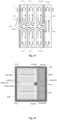
- the vertical circular lanes are 400, arranged in 20 groups of 20 elements. Since the first microchamber MCH is fundamentally divided by the horizontal lanes into two half-chambers, a top one and a bottom one, the vertical lanes are 200 in the top half and 200 in the bottom half. The structure is hence completely symmetrical.
- Each individual lane is able to displace a particle and rotate it using a three-phase protocol. It is possible in any case to extract from a lane a particle of interest using one of the (controllable) NCV points of exchange, positioned immediately on top of the horizontal lane HCONV_UP for the vertical lanes upwards and immediately underneath the horizontal lane HCONV_DOWN for the vertical lanes downwards.
- Each point of exchange is defined by a pair of electrodes, referred to, respectively, as “element” and "group” ( Figure 32 ). Since the group electrodes and element electrodes are 20, the number of the addressable exchanges is 400, equal to the number of the vertical lanes.
- the special-phase signal is the same for each lane within a group, so that the behaviour of the signal special phase and of the signals of a group electrode are the same for each conveyor of the group. The same does not apply to element electrodes. It is always possible, in this way, to transfer a particle of interest from a vertical conveyor to a horizontal conveyor in order to convey it as far as the programmable array and possibly to the exit point, without loading any other particle into the horizontal conveyor.
- the change of direction, i.e., the transfer from a vertical lane to a horizontal lane is made possible by an electrode guided by a special phase ( Figure 33 ).
- said electrode is located in the same phase as the signal of Phase 2, but in the case of a particle of interest, when all the other signals of Phase 2 remain negative (i.e., active) also the special signal becomes negative ( Figure 34 ), thus leaving the cell to be transferred through the point of contact if the element electrode and group electrode are active.
- the signal of the element is not in the negative phase (what is instead true for all the other 19 lanes not concerned in the exchange)
- the operation is the one illustrated in Figure 35 . In this way, the particles can be joined to the conveyors upwards and downwards.
- the particles of interest can be transferred into the completely programmable matrix array, in which it is possible to carry out complex operations, such as for example the division of clusters of particles.
- complex operations such as for example the division of clusters of particles.
- This is particularly useful, for example, when the mean density of cells per cage in the sample injected is equal to or greater than one. In this case, the probability of having a single cell in the cage decreases, and consequently it is likely for the cells of interest to form part of a cluster.
- the presence of the completely programmable matrix array enables segregation in different cages of the cells forming part of a cluster.
- a matrix array is a square of 5 ⁇ 5 completely programmable electrodes, as illustrated in Figure 36 , which shows the relative interaction thereof with the horizontal conveyors and auxiliary conveyor.
- the auxiliary lane HCONV_AUX can be used as support for the two horizontal lanes HCONV_UP and HCONV_DOWN, for example in the case of any malfunctioning due to clogging of particles, etc.
- points of exchange are provided, made with a double point of exchange, as illustrated in Figure 38 .
- the auxiliary lane can also be used to eliminate the undesired particles, particularly during the step of start-up of the apparatus.
- Figure 39 shows the left-hand end of the auxiliary lane, where it is possible to transfer the particles in the long dump lanes through an individual point of exchange.
- the exit lane RCONV is a 4-phase lane, which conveys the cells of interest out of the microchamber MCH and into the microchamber RCH .
- the path towards the exit point proceeds by zigzagging ( Figure 41 ) all the way through the microchamber RCH.
- the particles can be brought back into the array by means of the horizontal feedback lane HCONV_FB.
- the latter splits the exit lane in a symmetrical way, identifying in effect a top exit half-lane and a bottom exit half-lane. It should be noted that said half-lanes are completely independent of the operative standpoint, and it is consequently possible to use even just one of them.
- the active area of the apparatus is surrounded by a ring ( Figure 42 ), in turn made up of two concentric rings of electrodes in positive phase, followed by a ring of electrodes in positive phase alternating with dummy electrodes (for example floating electrodes), which are in turn followed by two rings of electrodes in positive phase.
- the dummy electrodes are aligned with the columns of the conveyors.
- the embodiment just described advantageously enables combination of the simplicity of programming and management (number of phases for control of the lanes downwards) with the precision (possibility of carrying out complex manipulations of the particles of interest inside the array, having the possibility of intervening independently on each of the individual cages that constitute it).
- Recognition can be combined with a method for counting cells obtained by combining the effect of the forces (F), through which to position each cell (or group of cells) in a point corresponding to an element of an array of sensors, and the capacity of identifying the presence of each cell (or group of cells) by means of said sensors. In this way it is possible, in addition to recognizing, also to count the particles of each type.
- the detection is made via impedance meter or optical sensors.
- impedance meter or optical sensors Of particular interest is the possibility of detecting the particles even without an active substrate, i.e., without transistors.
- Figure 43 shows a reading scheme according to the present invention for detecting the impedance of the individual intersections (Zcage_ij) between generic lines of row signals (Ri) and column signals (Cj), without undergoing the influence of the coupling between adjacent rows (Zrow) and columns (Zcol), which otherwise would render detection impossible, in so far as their value is typically dominant with respect to Zcage_ij.
- This reading scheme can be obtained with an electronic system with components external to the microfabricated chip, and hence compatible with the use of substrates without transistors, but can also be integrated on the chip in the case where transistors are available.
- An input stimulus (Vin), with zero mean value, is applied selectively to a row (Ri), enabling only its multiplexers MRi.
- the other row multiplexers MR1 ... MRi-1, MRi+1 ... MRm connect the remaining rows to ground.
- Vout can hence be used to derive Zcage_ij, with Vin and Zr known.
- the output Vout in general, can be processed, possibly together with the input Vin, by a block for processing the signal (PROC), of an analog or digital type, to produce one or more additional - analog or digital - outputs (OUT), representing the measurement of the impedance and hence of the presence or otherwise or also of the type of particle in the measurement point.
- PROC signal
- OUT additional - analog or digital - outputs
- a detection apparatus can be provided also independently of the use of the chip as actuator.
- the measurement of impedance does not entail the use of forces and can be effected between adjacent electrodes arranged in a regular way in a two-dimensional space by positioning the tissue in contact with the substrate on which the array of electrodes is located.
- the subject of the present invention is an apparatus that implements this technique by means of an array of blocks of electrodes, each constituted by at least one electrode connected to row signals and at least one electrode connected to column signals, such that the impedance between said electrodes can be evaluated by measuring the impedance between row and column.
- a possible particle located in the neighbourhood of each row and column intersection can in this way be detected by measuring the impedance between the row and column.
- a further possibility of detection of the particles is constituted by the use of optical sensors underneath the device, combined to the use of transparent electrodes (such as Indium Tin Oxide - ITO).
- the main characteristic of this technique lies in the possibility of aligning the particles to be detected with the elements (pixel) of the sensor, improving the sensitivity of the measurements and obtaining a biunique correspondence between particle and sensor element.
- This technique guarantees in fact that each particle can be located only and exclusively in the sensor area of just one element of the array of sensors.
- an array of external sensors set at a distance from the actuation device, in which the light reflected from above or transmitted from beneath is conveyed and focused by a series of lenses towards the sensor, the elements (pixel) of which are, however, aligned optically with the blocks of the array.
- a further possibility of detection of the particles is constituted by the use of optical sensors (OPTISENS) underneath the device, combined with the use of non-transparent electrodes.
- OPISENS optical sensors
- CAGE potential holes
- Shown as a particular case in Figure 44 is a simple embodiment of the apparatus forming the subject of the present invention, in which the array of electrodes (EL) is constituted by just one electrode in the form of a square grid (other geometrical shapes are obviously possible, such as rectangles, circles, hexagons, or triangles).
- blocks (BLOCK_i,j) are obtained, constituted ( Figure 44a ) by regions not coated with the metal of the electrode, where points of stable equilibrium (CAGE_i,j) are provided.
- a sensor OTISENS
- pixel photosensitive elements
- This apparatus is particularly useful for counting the particles contained in a liquid sample.
- the embodiment is limited to the alignment of the particles (BEAD) with the elements (pixel) of the array of sensors.
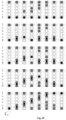
- Illustrated in Figure 45a is an enlarged image of the device, in which the blocks (BLOCK_i,j) and the microspheres (BEAD) entrapped in the points of stable equilibrium (CAGE_i,j) are clearly visible, whilst illustrated in Figure 45b is the processed signal corresponding to the same portion of device.
- the processing consists in an inversion of the levels of grey, followed by a blurring and a thresholding. From the resulting image an automatic count may be readily obtained.
- Similar results can be obtained using a contact sensor that gathers the light from beneath, as illustrated in Figure 46 , or integrated within the substrate itself.
- the advantage of the use of contact sensors lies in the fact that the use of the lenses of a microscope is not required. The result is an apparatus of reduced dimensions and hence portable.
- microlenses can be used, which can for example be provided on the top part of the cover (LID) for conveying the light onto the entrapped particle.
- Illustrated in Figure 47 is an example of this idea, in which it is shown schematically how the use of microlenses can improve the sensitivity of the measurement (gathering the light that otherwise would end up outside the sensitive region) and increase the contrast between the different levels of signal associated to the presence or absence of a particle (conveying all the rays of light into the centre of force of the cage, where the particle is positioned). It is moreover evident to persons skilled in the sector that the effects of lenses, parabolic dishes, prisms, mirrors, filters or polarizers can be combined for irradiating the apparatus.
- SENSHEAD one-dimensional array
- CAGE_i,j points of stable equilibrium
- an acquisition is effected in time sequence for each row (or column) of the array, displacing by a pitch (PITCH), after each acquisition, the array of sensors (pixel) with respect to the array of blocks or vice versa in the direction (HEADIR) parallel to the columns (or to the rows).
- PITCH pitch
- HEADIR direction parallel to the columns (or to the rows).
- a single photosensitive element to carry out a scan in time sequence of the entire array.
- a displacement of the sensor (SENSHEAD) is effected in the direction parallel to the rows, by a distance equal to the pitch between elements of the row.
- a displacement of the sensor is effected in the direction parallel to the columns, by a distance equal to the pitch between elements of the column.
- a further row is scanned, proceeding in the same manner up to completion of the entire array.
Landscapes
- Chemical & Material Sciences (AREA)
- Life Sciences & Earth Sciences (AREA)
- Health & Medical Sciences (AREA)
- Pathology (AREA)
- Physics & Mathematics (AREA)
- Analytical Chemistry (AREA)
- Biochemistry (AREA)
- General Health & Medical Sciences (AREA)
- General Physics & Mathematics (AREA)
- Immunology (AREA)
- Dispersion Chemistry (AREA)
- Molecular Biology (AREA)
- Electrochemistry (AREA)
- Chemical Kinetics & Catalysis (AREA)
- Engineering & Computer Science (AREA)
- Microelectronics & Electronic Packaging (AREA)
- Apparatus Associated With Microorganisms And Enzymes (AREA)
- Electrostatic Separation (AREA)
- Investigating Or Analyzing Materials By The Use Of Electric Means (AREA)
- Physical Or Chemical Processes And Apparatus (AREA)
- Investigating Or Analysing Materials By Optical Means (AREA)
Claims (14)
- Procédé pour la manipulation de particules (BEAD) au moyen d'au moins un réseau de blocs (BLOCK_i,j) d'électrodes, comprenant les étapes suivantes :i. la génération d'une première configuration de champ de force (F_i) qui présente au moins un premier point (CAGE_i,j) et au moins un deuxième point (CAGE_i,j+1) d'équilibre stable pour lesdites particules (BEAD), lesdits points étant positionnés, respectivement, sur un premier bloc (BLOCK_i,j) et sur un deuxième bloc (BLOCK_i,j+1) dudit réseau immédiatement adjacent au premier, et de sorte qu'au moins une particule (BEAD) est piégée dans ledit premier point d'équilibre stable (CAGE_i,j) ;ii. la génération d'au moins une deuxième configuration de champ de force (F_ii) de telle sorte qu'une particule (BEAD) est poussée à l'intérieur d'un bassin d'attraction dudit au moins un deuxième point d'équilibre stable (CAGE_i,j+1); etiii. la génération à nouveau de la première configuration de champ de force (F_i) de telle sorte que ladite particule (BEAD) est attirée vers le deuxième point d'équilibre stable (CAGE_i,j+1) ;ledit procédé étant caractérisé en ce que chaque bloc (BLOCK_i,j) d'électrodes du réseau est connecté électriquement à deux groupes de tensions (Vrow_i[p], Vcol_j [q]) répartis dans le réseau, respectivement, en lignes et en colonnes et connectés électriquement aux blocs d'électrodes qui partagent la même ligne ou la même colonne, ladite première configuration (F_i) et ladite deuxième configuration (F_ii) du champ de force étant générées au moyen d'au moins deux configurations différentes de premières tensions (Vrow_i [p] et Vcol_j [q]) appliquées aux électrodes du premier bloc du réseau (BLOCK_i,j) et de deuxièmes tensions (Vrow_i [p] et Vcol_j +1[q]) appliquées aux électrodes du deuxième bloc du réseau (BLOCK_i,j+1).
- Procédé selon la revendication 1, comprenant une exécution itérative des étapes i) à iii) sur une pluralité desdits blocs d'électrodes dudit réseau disposés de manière adjacente les uns aux autres deux à deux de manière à disperser au moins une particule (BEAD) présente dans au moins un desdits blocs d'électrodes (BLOCK_i,j) le long de trajectoires constituées par une succession desdits blocs d'électrodes adjacents.
- Procédé selon la revendication 1 ou la revendication 2, caractérisé en ce que chaque bloc d'électrodes (BLOC_i,j) du réseau est constitué par : au moins un premier ensemble d'électrodes connectées à des tensions (Vphip, Vphin) au moyen desdits signaux de ligne (Vrow_i[p]) ; au moins un deuxième ensemble d'électrodes connectées à des tensions (Vphip, Vphin) au moyen desdits signaux de colonne (Vcol_j[q]) ; et au moins une électrode connectée aux tensions (Vphip, Vphin) au moyen d'un signal (Vcore) commun à tous les blocs d'électrodes du réseau et tel que chaque paire de blocs d'électrodes adjacents (BLOCK_i,j et BLOCK_i,j+1) puisse adopter ladite au moins une deuxième configuration de champ de force (F_ii) tandis que tous les autres blocs d'électrodes du réseau conservent ladite première configuration (F_i), au moyen d'une modification des tensions appliquées via lesdits signaux de ligne (Vrow_i [p]) et lesdits signaux de colonne (Vcol_j [q]) connectés à ladite paire de blocs adjacents (BLOCK_i,j et BLOCK_i,j+1) d'électrodes.
- Procédé selon la revendication 1 ou la revendication 2, caractérisé en ce que chaque bloc d'électrodes (BLOCK_i,j) du réseau est constitué d'au moins un premier ensemble d'électrodes connectées à des tensions (Vphip, Vphin) au moyen de circuits électroniques (MUX_i,j et AND_i,j) commandés au moyen d'un premier ensemble de signaux de ligne (row_i) et signaux de colonne (col_j) numériques et par au moins une électrode connectée à des tensions (Vphip, Vphin) au moyen d'un deuxième ensemble de signaux (Vcore) communs à tous les blocs d'électrodes (BLOCK_i,j) du réseau, de telle sorte que chaque paire de blocs d'électrodes adjacents (BLOCK_i,j et BLOCK_i,j+1) puisse adopter ladite deuxième configuration de champ de force (F_ii) tandis que tous les autres blocs d'électrodes du réseau conservent ladite première configuration (F_i), au moyen d'une modification des tensions appliquées à ladite paire de blocs adjacents (BLOCK_i,j et BLOCK_i,j+1) d'électrodes via ledit premier ensemble de signaux de ligne (row_i) et de signaux de colonne (col_j), qui sont connectés aux circuits électroniques (MUX_i,j et AND_i,j) desdits blocs (BLOCK_i,j et BLOCK_i,j+1) d'électrodes.
- Procédé selon l'une des revendications précédentes, caractérisé en ce qu'une détection et/ou une caractérisation et/ou une quantification et/ou une reconnaissance de cellules ou de particules (BEAD) en suspension aqueuse ou agrégées dans des tissus est réalisée, comprenant une mesure d'impédance entre au moins une première électrode connectée à au moins un signal de première ligne et au moins une deuxième électrode adjacente à ladite première électrode, ladite deuxième électrode étant connectée à au moins un signal de première colonne, dans lequel ladite mesure entre lesdites au moins deux électrodes adjacentes est réalisée en évaluant l'impédance entre ledit signal de première ligne et ledit signal de première colonne.
- Procédé selon la revendication 5, caractérisé en ce qu'il est réalisé sur au moins une dite particule (BEAD) située en au moins un dit point (CAGE_i,j ; CAGE_i,j+l) d'équilibre stable pour lesdites particules (BEAD).
- Appareil pour la manipulation de particules (BEAD), caractérisé en ce qu'il comprend :i. un réseau bidimensionnel d'électrodes formant un réseau de blocs (BLOC_i,j) d'électrodes, les blocs étant agencés en lignes et en colonnes, chaque bloc comprenant : un premier ensemble d'électrodes configurées pour être connectées à des signaux de colonne (Vcol_j[q]) communs à tous les premiers ensembles de la même colonne de blocs ; un deuxième ensemble d'électrodes configurées pour être connectées à des signaux de ligne (Vrow_i[p]) communs à tous les deuxièmes ensembles de la même ligne de blocs ; et un troisième ensemble d'électrodes configurées pour être connectées à des signaux communs à tous les blocs d'électrodes (BLOCK_i,j) du réseau d'électrodes ;dans lequel l'appareil est configuré pour appliquer depuis l'extérieur une tension périodique en phase avec tous les signaux de ligne (Vrow_i) et les signaux de colonne (Vcol_j) et une tension périodique en opposition de phase avec lesdits signaux communs à tous les blocs d'électrodes (BLOCK_i,j),de telle sorte que pour chaque paire formée par un premier bloc (BLOCK_i,j) d'électrodes et par un deuxième bloc (BLOCK_i,j+1) d'électrodes adjacent au premier bloc, l'appareil génère au moins une première configuration (F_i) et une deuxième configuration (F_ii) de champ de force obtenues en appliquant deux configurations différentes de deux tensions (Vphin, Vphip) aux signaux de ligne (Vrow_i [p]) et aux signaux de colonne (Vcol_j [q] et Vcol_j+1[q]) ; ladite première configuration (F_i) de champ de force étant conçue pour créer au moins un premier point (CAGE_i,j) et au moins un deuxième point (CAGE_i,j+1) d'équilibre stable pour lesdites particules (BEAD), lesdits points étant positionnés, respectivement, sur ledit premier bloc (BLOCK_i,j) et sur ledit deuxième bloc (BLOCK_i,j+1) d'électrodes du réseau ; et ladite deuxième configuration (F_ii) de champ de force étant conçue pour pousser ladite particule (BEAD) éventuellement piégée dans ledit premier point d'équilibre stable (CAGE_i,j) dans un bassin d'attraction dudit au moins un deuxième point d'équilibre stable (CAGE_i,j+1).
- Appareil selon la revendication 7, caractérisé en ce que ledit premier ensemble d'électrodes de chacun desdits blocs (BLOCK_i,j) comprend au moins une première électrode (ring_i,j_1) connectée à un signal de colonne (Vcol_j) commun à tous les ensembles de la même colonne ; ledit deuxième ensemble d'électrodes de chaque bloc comprend au moins une deuxième électrode (ring_i,j_2) connectée à un signal de ligne (Vrow_i) commun à tous les ensembles de la même ligne ; et ledit troisième ensemble d'électrodes de chaque bloc comprend au moins une troisième électrode (EL_i,j) connectée à un signal commun (Vcore), dans lequel ladite troisième électrode (EL_i,j) est entourée par ladite première électrode (ring_i,j_1) et ladite troisième électrode (EL_i,j) et ladite première électrode (ring_i,j_1) sont entourées par ladite deuxième électrode (ring_i,j_2).
- Appareil selon la revendication 7, caractérisé en ce que ledit premier ensemble d'électrodes de chaque dit bloc (BLOCK_i,j) comprend au moins une première électrode (elle_j) connectée à un signal de colonne (Venable_j) commun à tous les ensembles de la même colonne ; ledit deuxième ensemble d'électrodes de chaque bloc comprend au moins une deuxième électrode (wallx_i) connectée à un signal de ligne (Vrow_i[x]) commun à tous les groupes de la même ligne ; et ledit troisième ensemble d'électrodes de chaque bloc comprend au moins une troisième électrode (EL_i,j) connectée à un signal commun (Vcore) ; dans lequel ledit deuxième ensemble d'électrodes de chaque bloc comprend en outre au moins une quatrième électrode (wally_i) connectée à un signal de ligne (Vrow_i[y]) commun à tous les ensembles de la même ligne ; et où ladite troisième électrode (EL_i,j) est flanquée dans deux directions adjacentes par ladite première électrode (elle_j), et ladite première électrode (elle_j) est flanquée par ladite deuxième électrode (wallx_i) et ladite quatrième électrode (wally_i).
- Appareil selon la revendication 7, caractérisé en ce que ledit premier ensemble d'électrodes de chaque dit bloc (BLOCK_i,j) se distingue en électrodes à indice de colonne paire et à indice de colonne impaire, tandis que ledit deuxième ensemble d'électrodes de chaque dit bloc (BLOCK_i,j) se distingue en électrodes à indice de ligne paire et à indice de ligne impaire ; dans lequel ledit troisième ensemble de chaque bloc comprend au moins une troisième électrode (EL_i,j) connectée à un signal commun (Vcore) ; et dans lequel ledit premier ensemble comprend au moins une première électrode connectée à un signal de colonne (Vcol_i[D1]) commun aux blocs de la même colonne avec un indice de colonne pair ou à un signal de colonne (Vcol_i[D2]) commun aux blocs de la même colonne avec un indice de colonne impair ; et au moins une deuxième électrode connectée à un signal de colonne (Vcol_i[U1]) commun aux blocs de la même colonne avec un indice de colonne pair ou à un signal de colonne (Vcol_i[U2]) commun aux blocs de la même colonne avec un indice de colonne impair ; et dans lequel ledit deuxième ensemble comprend au moins une quatrième électrode connectée à un signal de ligne (Vrow_i[R1]) commun aux blocs de la même ligne avec un indice de ligne pair ou à un signal de ligne (Vrow_i[R2]) commun aux blocs de la même ligne avec un indice de ligne impair et au moins une cinquième électrode connectée à un signal de ligne (Vrow_i[L1]) commun aux blocs de la même ligne avec un indice de ligne pair ou à un signal de ligne (Vrow_i[L2]) commun aux blocs de la même ligne avec un indice de ligne impair.
- Appareil pour la manipulation de particules (BEAD), selon la revendication 7, dans lequel :i. chaque bloc comprend : un premier ensemble d'au moins une première électrode (EL_i,j) connectée à un signal commun à tous les blocs ; et un deuxième ensemble d'au moins une deuxième électrode (ring_i,j) connectée à un signal de sortie d'un circuit (MUX_i,j), piloté par au moins un deuxième circuit (AND_i,j) ;ii. des moyens pour générer au moins deux tensions différentes (Vphin, Vphip) ; etiii. des moyens pour générer des signaux de ligne (row_i) communs à tous les blocs (BLOCK_i,j) de la même ligne et des signaux de colonne (col_j) communs à tous les blocs (BLOCK_i,j) de la même colonne pour piloter lesdits circuits (AND_i,j) et au moyen desquels la tension (Vphin, Vphip) à connecter à ladite au moins une deuxième électrode (ring_i,j) de chaque bloc (BLOCK_i,j) est sélectionnée ;où pour chaque paire formée par un premier bloc (BLOCK_i,j) et un deuxième bloc (BLOCK_i,j+l) adjacent au premier bloc, lesdits moyens de génération de signaux déterminent la création d'au moins une première configuration (F_i) et une deuxième configuration (F_ii) de champ de force en appliquant deux configurations différentes de valeurs aux signaux de ligne (Vrow_i) et aux signaux de colonne (Vcol_j et Vcol_j+1) de telle sorte que ladite première configuration (F_i) de champ de force présente au moins un premier point (CAGE_i,j) d'équilibre stable et au moins un deuxième point (CAGE_i,j+1) d'équilibre stable pour lesdites particules (BEAD), lesdits points étant positionnés, respectivement, sur ledit premier bloc (BLOCK_i,j) et sur ledit deuxième bloc (BLOCK_i,j+l) du réseau, et étant tels que ladite deuxième configuration (F_ii) du champ de force est conçue pour pousser ladite particule (BEAD) qui est éventuellement piégée dans ledit premier point d'équilibre stable (CAGE_i,j) dans un bassin d'attraction dudit au moins un deuxième point d'équilibre stable (CAGE_i,j+1).
- Appareil selon la revendication 11, caractérisé en ce que ledit premier ensemble d'électrodes de chaque dit bloc (BLOCK_i,j) comprend au moins une première électrode (EL_i,j) connectée à un signal commun à tous les blocs constitué par une (Vphin) desdites tensions différentes ; et tel que ledit deuxième ensemble d'électrodes comprend au moins une deuxième électrode (ring_i,j) connectée au signal de sortie d'un circuit qui constitue un déviateur (MUX_i,j), de sorte qu'un seul des deux signaux différents (Vphin, Vphip) à l'entrée du déviateur peut être connecté à la sortie du déviateur selon la valeur du signal de sortie d'un autre circuit (AND_i,j), qui réalise une fonction logique entre les valeurs des signaux de ligne (row_i) et des signaux de colonne (col_j) ; et dans lequel ladite première électrode (EL_i,j) est entourée par ladite deuxième électrode (ring_i,j).
- Appareil selon l'une quelconque des revendications 7 à 12, caractérisé en ce qu'il comprend au moins deux micro-chambres et en ce qu'il présente un agencement desdites électrodes dudit réseau d'électrodes tel qu'il est possible de déplacer lesdites particules (BEAD) d'une micro-chambre à l'autre et inversement en pilotant lesdites électrodes avec des signaux appropriés.
- Appareil selon l'une quelconque des revendications 7 à 13, caractérisé en ce que lesdites électrodes sont réalisées sur un substrat sensiblement plan (SUB) ; et en ce qu'il comprend une autre électrode (ITO) réalisée sur un autre substrat (LID) fixé à distance dudit premier substrat (SUB) et en regard de celui-ci, ladite autre électrode (ITO) étant connectée électriquement à un autre signal électrique.
Applications Claiming Priority (3)
| Application Number | Priority Date | Filing Date | Title |
|---|---|---|---|
| IT000481A ITBO20050481A1 (it) | 2005-07-19 | 2005-07-19 | Metodo ed apparato per la manipolazione e/o l'individuazione di particelle |
| PCT/IB2006/001984 WO2007010367A2 (fr) | 2005-07-19 | 2006-07-19 | Procede et appareil de manipulation et/ou de detection de particules |
| EP06795130.1A EP1909965B1 (fr) | 2005-07-19 | 2006-07-19 | Procede et appareil de manipulation de particules |
Related Parent Applications (2)
| Application Number | Title | Priority Date | Filing Date |
|---|---|---|---|
| EP06795130.1A Division-Into EP1909965B1 (fr) | 2005-07-19 | 2006-07-19 | Procede et appareil de manipulation de particules |
| EP06795130.1A Division EP1909965B1 (fr) | 2005-07-19 | 2006-07-19 | Procede et appareil de manipulation de particules |
Publications (2)
| Publication Number | Publication Date |
|---|---|
| EP3851196A1 EP3851196A1 (fr) | 2021-07-21 |
| EP3851196B1 true EP3851196B1 (fr) | 2024-02-07 |
Family
ID=37400947
Family Applications (2)
| Application Number | Title | Priority Date | Filing Date |
|---|---|---|---|
| EP06795130.1A Active EP1909965B1 (fr) | 2005-07-19 | 2006-07-19 | Procede et appareil de manipulation de particules |
| EP21161552.1A Active EP3851196B1 (fr) | 2005-07-19 | 2006-07-19 | Procédé et appareil de manipulation et/ou de détection de particules |
Family Applications Before (1)
| Application Number | Title | Priority Date | Filing Date |
|---|---|---|---|
| EP06795130.1A Active EP1909965B1 (fr) | 2005-07-19 | 2006-07-19 | Procede et appareil de manipulation de particules |
Country Status (10)
| Country | Link |
|---|---|
| US (2) | US8641880B2 (fr) |
| EP (2) | EP1909965B1 (fr) |
| JP (2) | JP5349044B2 (fr) |
| KR (1) | KR101336157B1 (fr) |
| CN (2) | CN101267889B (fr) |
| CA (2) | CA2926639C (fr) |
| DK (2) | DK1909965T3 (fr) |
| ES (2) | ES2879332T3 (fr) |
| IT (1) | ITBO20050481A1 (fr) |
| WO (1) | WO2007010367A2 (fr) |
Families Citing this family (53)
| Publication number | Priority date | Publication date | Assignee | Title |
|---|---|---|---|---|
| US7329545B2 (en) * | 2002-09-24 | 2008-02-12 | Duke University | Methods for sampling a liquid flow |
| US6911132B2 (en) | 2002-09-24 | 2005-06-28 | Duke University | Apparatus for manipulating droplets by electrowetting-based techniques |
| ITBO20040420A1 (it) | 2004-07-07 | 2004-10-07 | Type S R L | Macchina per taglio e formatura di piattine metalliche |
| DK1859330T3 (da) | 2005-01-28 | 2012-10-15 | Univ Duke | Apparater og fremgangsmåder til håndtering af små dråber på et trykt kredsløbskort |
| ITBO20050481A1 (it) | 2005-07-19 | 2007-01-20 | Silicon Biosystems S R L | Metodo ed apparato per la manipolazione e/o l'individuazione di particelle |
| ITBO20050646A1 (it) * | 2005-10-26 | 2007-04-27 | Silicon Biosystem S R L | Metodo ed apparato per la caratterizzazione ed il conteggio di particelle |
| DE102006002462A1 (de) * | 2006-01-18 | 2007-07-19 | Evotec Technologies Gmbh | Elektrischer Feldkäfig und zugehöriges Betriebsverfahren |
| ITTO20060226A1 (it) | 2006-03-27 | 2007-09-28 | Silicon Biosystem S P A | Metodo ed apparato per il processamento e o l'analisi e o la selezione di particelle, in particolare particelle biologiche |
| ITTO20060273A1 (it) | 2006-04-12 | 2007-10-13 | Silicon Biosystem S P A | Metodi ed apparati per la selezione e/o il processamento di particellle, in particolare per la lisi selettiva e/o ottimizzata di cellule |
| ITTO20060586A1 (it) | 2006-08-07 | 2008-02-08 | Silicon Biosystems Spa | Metodo e dispositivo per la manipolazione di particelle mediante la sovrapposizione di campi di forza |
| ITTO20070307A1 (it) | 2007-05-04 | 2008-11-05 | Silicon Biosystems Spa | Metodo e dispositivo per la diagnosi prenatale non-invasiva |
| US8268246B2 (en) | 2007-08-09 | 2012-09-18 | Advanced Liquid Logic Inc | PCB droplet actuator fabrication |
| ITBO20070588A1 (it) | 2007-08-13 | 2009-02-14 | Silicon Biosystems Spa | Metodo per legare uno strato di silicone ad un substrato di polimero metacrilico |
| EP2042239A1 (fr) * | 2007-09-10 | 2009-04-01 | Koninklijke Philips Electronics N.V. | Dispositif diélectrophorétique et procédé d'études de membrane cellulaire |
| TWI375023B (en) * | 2007-10-05 | 2012-10-21 | Univ Nat Taiwan | A cellular microarray and its microfabrication method |
| ITTO20070771A1 (it) | 2007-10-29 | 2009-04-30 | Silicon Biosystems Spa | Metodo e apparato per la identificazione e manipolazione di particelle |
| EP2350630A4 (fr) * | 2008-10-31 | 2012-03-28 | Agency Science Tech & Res | Dispositif et procédé de détection d'un analyte d'un échantillon |
| IT1391619B1 (it) | 2008-11-04 | 2012-01-11 | Silicon Biosystems Spa | Metodo per l'individuazione, selezione e analisi di cellule tumorali |
| US10895575B2 (en) | 2008-11-04 | 2021-01-19 | Menarini Silicon Biosystems S.P.A. | Method for identification, selection and analysis of tumour cells |
| JP5834001B2 (ja) | 2009-03-17 | 2015-12-16 | シリコン・バイオシステムズ・ソシエタ・ペル・アチオニ | 細胞を分離するためのマイクロ流体デバイス |
| IT1397819B1 (it) | 2009-12-17 | 2013-02-04 | Silicon Biosystems Spa | Sistema microfluidico |
| US8653832B2 (en) * | 2010-07-06 | 2014-02-18 | Sharp Kabushiki Kaisha | Array element circuit and active matrix device |
| JP5617530B2 (ja) * | 2010-10-29 | 2014-11-05 | ソニー株式会社 | 細胞分取装置及び細胞分取方法 |
| IT1403518B1 (it) | 2010-12-22 | 2013-10-31 | Silicon Biosystems Spa | Dispositivo microfluidico per la manipolazione di particelle |
| US8828336B2 (en) * | 2011-02-02 | 2014-09-09 | Sharp Kabushiki Kaisha | Active matrix device |
| CN102671722B (zh) * | 2011-02-17 | 2015-03-11 | 王崇智 | 基于微电极阵列结构的现场可编程芯片实验室 |
| CN102671723B (zh) * | 2011-02-17 | 2015-03-11 | 王崇智 | 介质上电润湿微电极阵列结构上的液滴处理方法 |
| TWI510295B (zh) * | 2011-02-17 | 2015-12-01 | Gary Wang | 基於微電極陣列結構的現場可程式設計晶片實驗室與液滴處理方法 |
| KR20130009504A (ko) | 2011-07-15 | 2013-01-23 | 삼성전자주식회사 | 개구 조절 방법 및 개구 조절 소자 |
| ITTO20110990A1 (it) | 2011-10-28 | 2013-04-29 | Silicon Biosystems Spa | Metodo ed apparato per l'analisi ottica di particelle a basse temperature |
| ITBO20110766A1 (it) | 2011-12-28 | 2013-06-29 | Silicon Biosystems Spa | Dispositivi, apparato, kit e metodo per il trattamento di un campione biologico |
| US8764958B2 (en) * | 2012-08-24 | 2014-07-01 | Gary Chorng-Jyh Wang | High-voltage microfluidic droplets actuation by low-voltage fabrication technologies |
| JP6239562B2 (ja) * | 2015-09-14 | 2017-11-29 | 株式会社東芝 | 照明デバイスおよびそれを備えるバイオ情報計測装置 |
| US10078986B2 (en) * | 2015-09-15 | 2018-09-18 | Sharp Life Science (Eu) Limited | Active matrix device and method of driving |
| IT201600104601A1 (it) | 2016-10-18 | 2018-04-18 | Menarini Silicon Biosystems Spa | Sistema microfluidico |
| SG11201903247VA (en) * | 2016-10-18 | 2019-05-30 | Menarini Silicon Biosystems Spa | Microfluidic device, microfluidic system and method for the isolation of particles |
| US10330919B2 (en) * | 2017-03-31 | 2019-06-25 | Sharp Life Science (Eu) Limited | AM-EWOD device and control methods with intermittent actuation patterns |
| IT201700105911A1 (it) | 2017-09-21 | 2019-03-21 | Menarini Silicon Biosystems Spa | Metodo ed apparato per la riduzione del volume di un campione |
| IT201700105948A1 (it) | 2017-09-21 | 2019-03-21 | Menarini Silicon Biosystems Spa | Metodo e sistema microfluidico per il recupero di particelle |
| CN109799271B (zh) * | 2018-04-23 | 2020-07-10 | 京东方科技集团股份有限公司 | 微流控检测电路、系统、方法 |
| CN108627969B (zh) * | 2018-05-11 | 2020-08-18 | 南京晶奥微光电技术有限公司 | 一种双稳态电润湿结构及其制备工艺 |
| JP6742618B2 (ja) * | 2018-06-11 | 2020-08-19 | シャープ株式会社 | 生体粒子観察装置および生体粒子観察方法 |
| CN112449682B (zh) * | 2018-08-01 | 2024-03-08 | 澳门大学 | 用于芯片上微流体分配的设备和方法 |
| CN109011213A (zh) * | 2018-08-17 | 2018-12-18 | 江苏莱福医疗器械科技有限公司 | 一种放射性粒子自动排序装置 |
| US10978007B2 (en) * | 2018-12-03 | 2021-04-13 | Sharp Life Science (Eu) Limited | AM-EWOD circuit configuration with sensing column detection circuit |
| NL2023366B1 (en) * | 2019-02-08 | 2020-08-19 | Illumina Inc | Methods and devices for mixing in a microfluidic system |
| IT201900002777A1 (it) | 2019-02-26 | 2020-08-26 | Menarini Silicon Biosystems Spa | Metodo e sistema microfluidico per l'isolamento di particelle |
| CN110193386B (zh) * | 2019-06-04 | 2021-07-20 | 香港理工大学深圳研究院 | 一种基于介电电泳/电浸润效应的微流芯片 |
| CN111073793B (zh) * | 2019-12-28 | 2021-09-17 | 中国科学院长春光学精密机械与物理研究所 | 一种离心式微流控芯片、制作方法及其应用方法 |
| DE102020214957A1 (de) * | 2020-11-27 | 2022-06-02 | Karlsruher Institut für Technologie, Körperschaft des öffentlichen Rechts | Anordnung und System zur Erzeugung von Flüssigkeitsströmen |
| IT202100013715A1 (it) | 2021-05-26 | 2022-11-26 | Menarini Silicon Biosystems Spa | Metodo e sistema microfluidico per l'isolamento di particelle |
| CN116408161A (zh) * | 2021-12-31 | 2023-07-11 | 彩科(苏州)生物科技有限公司 | 具有提高的捕获效率的微流体设备及方法 |
| TWI837762B (zh) * | 2022-08-10 | 2024-04-01 | 醫華生技股份有限公司 | 非接觸式分選裝置與其光感應結構、及生物微粒分選設備 |
Family Cites Families (120)
| Publication number | Priority date | Publication date | Assignee | Title |
|---|---|---|---|---|
| JPS58211272A (ja) | 1982-06-02 | 1983-12-08 | Hitachi Ltd | 閾値決定法 |
| FI833076A0 (fi) | 1983-08-30 | 1983-08-30 | Labsystems Oy | Anordning foer maetning av uppvaermbara vaetskeprov |
| US4682007A (en) | 1986-04-17 | 1987-07-21 | Hollander James M | Defogging and deicing shield structure |
| US5252493A (en) | 1986-09-22 | 1993-10-12 | Nippon Telegraph And Telephone Corporation | Laser magnetic immunoassay method and apparatus therefor |
| DE3931851A1 (de) * | 1989-09-23 | 1991-04-11 | Heinrich Joern Dipl Chem | Computergesteuerter potentialdifferenz-leitfaehigkeitsscanner fuer traegerfreie elektrophorese |
| US5641628A (en) | 1989-11-13 | 1997-06-24 | Children's Medical Center Corporation | Non-invasive method for isolation and detection of fetal DNA |
| JPH05501612A (ja) | 1989-11-13 | 1993-03-25 | チルドレンズ・メデイカル・センター・コーポレーシヨン | 胎児dna単離および検出のための非侵入性方法 |
| GB8926781D0 (en) | 1989-11-27 | 1990-01-17 | Nat Res Dev | Identification of micro-organisms |
| US5840482A (en) | 1990-10-10 | 1998-11-24 | The Regents Of The University Of California | Y chromosome specific nucleic acid probe and method for determining the Y chromosome in situ |
| US6149789A (en) | 1990-10-31 | 2000-11-21 | Fraunhofer Gesellschaft Zur Forderung Der Angewandten Forschung E.V. | Process for manipulating microscopic, dielectric particles and a device therefor |
| DE4214320C1 (fr) | 1992-05-04 | 1993-06-03 | Erwin Halder Kg, 7958 Laupheim, De | |
| JPH07301595A (ja) * | 1994-05-09 | 1995-11-14 | Toa Medical Electronics Co Ltd | 粒子測定装置およびその粒子測定方法 |
| DE19500660B4 (de) | 1994-12-10 | 2007-12-27 | Fraunhofer-Gesellschaft zur Förderung der angewandten Forschung e.V. | Vorrichtung und Verfahren zur Manipulation mikroskopisch kleiner Partikel sowie deren Verwendung |
| US5856174A (en) | 1995-06-29 | 1999-01-05 | Affymetrix, Inc. | Integrated nucleic acid diagnostic device |
| US5833860A (en) | 1995-08-28 | 1998-11-10 | Millipore Investment Holdings Limited | Centrifugal adsorptive sample preparation device and method |
| US5888370A (en) | 1996-02-23 | 1999-03-30 | Board Of Regents, The University Of Texas System | Method and apparatus for fractionation using generalized dielectrophoresis and field flow fractionation |
| US5945281A (en) | 1996-02-02 | 1999-08-31 | Becton, Dickinson And Company | Method and apparatus for determining an analyte from a sample fluid |
| US5942443A (en) | 1996-06-28 | 1999-08-24 | Caliper Technologies Corporation | High throughput screening assay systems in microscale fluidic devices |
| GB9615775D0 (en) * | 1996-07-26 | 1996-09-04 | British Tech Group | Apparatus and method for characterising particles using dielectrophoresis |
| DK0925494T3 (da) | 1996-09-04 | 2002-07-01 | Scandinavian Micro Biodevices | Mikrostrømningssystem til partikelseparation og analyse |
| WO1999017883A1 (fr) | 1997-10-06 | 1999-04-15 | California Institute Of Technology | Transport electrostatique de particules |
| EP1179585B1 (fr) | 1997-12-24 | 2008-07-09 | Cepheid | Dispositif et procédé de Lyse |
| US20020172987A1 (en) | 1998-02-12 | 2002-11-21 | Terstappen Leon W.M.M. | Methods and reagents for the rapid and efficient isolation of circulating cancer cells |
| US6830729B1 (en) | 1998-05-18 | 2004-12-14 | University Of Washington | Sample analysis instrument |
| US6203683B1 (en) | 1998-11-09 | 2001-03-20 | Princeton University | Electrodynamically focused thermal cycling device |
| US6294063B1 (en) | 1999-02-12 | 2001-09-25 | Board Of Regents, The University Of Texas System | Method and apparatus for programmable fluidic processing |
| JP2000292480A (ja) | 1999-03-31 | 2000-10-20 | Seiko Epson Corp | 恒温槽 |
| US6149489A (en) | 1999-04-08 | 2000-11-21 | Johnson; Russell G. | Infant amusement device |
| US20030228565A1 (en) | 2000-04-26 | 2003-12-11 | Cytokinetics, Inc. | Method and apparatus for predictive cellular bioinformatics |
| IT1309430B1 (it) * | 1999-05-18 | 2002-01-23 | Guerrieri Roberto | Metodo ed apparato per la manipolazione di particelle per mezzo delladielettroforesi |
| US6942776B2 (en) | 1999-05-18 | 2005-09-13 | Silicon Biosystems S.R.L. | Method and apparatus for the manipulation of particles by means of dielectrophoresis |
| AU4487100A (en) | 1999-05-19 | 2000-12-05 | Qualcomm Incorporated | Apparatus and method for interfacing personal electronics to exercise equipment |
| DE60022025T2 (de) | 1999-05-28 | 2006-06-29 | Cepheid, Sunnyvale | Anlage zum brechen von zellen |
| WO2001021311A1 (fr) | 1999-09-20 | 2001-03-29 | Princeton Separations | Dispositif de traitement de multiples echantillons |
| US6824664B1 (en) | 1999-11-04 | 2004-11-30 | Princeton University | Electrode-less dielectrophorises for polarizable particles |
| DE60130052T2 (de) | 2000-04-13 | 2008-05-15 | Wako Pure Chemical Industries, Ltd. | Elektroden-Bau für dielektrophoretische Anordnung und dielektrophoretische Trennung |
| US6899849B2 (en) | 2000-07-28 | 2005-05-31 | The Regents Of The University Of California | Integrated sensor |
| WO2002012896A1 (fr) | 2000-08-08 | 2002-02-14 | Aviva Biosciences Corporation | Techniques de manipulations de fragments dans des systemes microfluidiques |
| US6833542B2 (en) | 2000-11-13 | 2004-12-21 | Genoptix, Inc. | Method for sorting particles |
| AU2002223503A1 (en) | 2000-11-24 | 2002-06-03 | Novo-Nordisk A/S | Decondenser unit |
| DE10059152C2 (de) | 2000-11-29 | 2003-03-27 | Evotec Ag | Mikrosystem zur dielektrischen und optischen Manipulierung von Partikeln |
| US6764583B2 (en) | 2000-12-13 | 2004-07-20 | The Regents Of The University Of California | Using impedance measurements for detecting pathogens trapped in an electric field |
| JP3868788B2 (ja) * | 2001-10-15 | 2007-01-17 | 株式会社東芝 | 電気泳動表示装置 |
| JP2002311461A (ja) | 2001-04-17 | 2002-10-23 | Sharp Corp | 表示素子 |
| US6929730B2 (en) | 2001-05-01 | 2005-08-16 | Cheng Sheng Lee | Two dimensional microfluidic gene scanner |
| ITTO20010411A1 (it) | 2001-05-02 | 2002-11-02 | Silicon Biosystems S R L | Metodo e dispositivo per l'esecuzione di test e saggi ad alta processivita' ed alto valore biologico su cellule e/o composti. |
| US20050009101A1 (en) | 2001-05-17 | 2005-01-13 | Motorola, Inc. | Microfluidic devices comprising biochannels |
| US7556733B2 (en) | 2001-06-15 | 2009-07-07 | Mds Analytical Technologies (Us) Inc. | Low volume filtration column devices and methods of filtering therewith |
| US20030073110A1 (en) | 2001-07-03 | 2003-04-17 | Masaharu Aritomi | Method for isolating nucleic acid and a cartridge for chemical reaction and for nucleic acid isolation |
| ITTO20010801A1 (it) | 2001-08-07 | 2003-02-07 | Silicon Biosystems S R L | Metodo e dispositivo per analisi biomolecolari integrate. |
| ATE325364T1 (de) | 2001-08-23 | 2006-06-15 | Koninkl Philips Electronics Nv | Elektrophoretische anzeigevorrichtung |
| JP2005507997A (ja) | 2001-10-26 | 2005-03-24 | イムニベスト・コーポレイション | 同一試料についての包括的核酸および形態学的特徴のマルチパラメーター分析 |
| US20030098271A1 (en) | 2001-11-26 | 2003-05-29 | Ralph Somack | Capsule and tray systems for combined sample collection, archiving, purification, and PCR |
| US7163612B2 (en) * | 2001-11-26 | 2007-01-16 | Keck Graduate Institute | Method, apparatus and article for microfluidic control via electrowetting, for chemical, biochemical and biological assays and the like |
| JP3845583B2 (ja) * | 2002-01-09 | 2006-11-15 | 株式会社東芝 | 電気泳動表示装置及びその製造方法 |
| DE10203636B4 (de) | 2002-01-30 | 2004-02-12 | Testo Gmbh & Co | Vorrichtung zum Nachweis von Partikeln in einem Fluid |
| US7147763B2 (en) * | 2002-04-01 | 2006-12-12 | Palo Alto Research Center Incorporated | Apparatus and method for using electrostatic force to cause fluid movement |
| TWI240842B (en) * | 2002-04-24 | 2005-10-01 | Sipix Imaging Inc | Matrix driven electrophoretic display with multilayer back plane |
| US20060086309A1 (en) | 2002-06-24 | 2006-04-27 | Fluiding Corporation | Recirculating fluidic network and methods for using the same |
| US20040011652A1 (en) | 2002-07-16 | 2004-01-22 | Bressler Vincent Edward | Separation of particles using multiple conductive layers |
| US7329545B2 (en) | 2002-09-24 | 2008-02-12 | Duke University | Methods for sampling a liquid flow |
| US6911132B2 (en) | 2002-09-24 | 2005-06-28 | Duke University | Apparatus for manipulating droplets by electrowetting-based techniques |
| EP2359689B1 (fr) | 2002-09-27 | 2015-08-26 | The General Hospital Corporation | Dispositif microfluidique pour la séparation de cellules et usage du dispositif |
| US6888721B1 (en) | 2002-10-18 | 2005-05-03 | Atec Corporation | Electrohydrodynamic (EHD) thin film evaporator with splayed electrodes |
| US7932098B2 (en) | 2002-10-31 | 2011-04-26 | Hewlett-Packard Development Company, L.P. | Microfluidic system utilizing thin-film layers to route fluid |
| KR101005970B1 (ko) | 2002-11-19 | 2011-01-05 | 가부시키가이샤 아이 디자인 | 혈장 또는 혈청 분리막, 및 혈장 또는 혈청 분리막을이용한 필터 장치 |
| US7445926B2 (en) | 2002-12-30 | 2008-11-04 | The Regents Of The University Of California | Fluid control structures in microfluidic devices |
| US7338637B2 (en) | 2003-01-31 | 2008-03-04 | Hewlett-Packard Development Company, L.P. | Microfluidic device with thin-film electronic devices |
| DE10304653B4 (de) | 2003-02-05 | 2005-01-27 | Evotec Technologies Gmbh | Mehrparametrige Detektion in einem fluidischen Mikrosystem |
| GB0303305D0 (en) | 2003-02-12 | 2003-03-19 | Secr Defence | Apparatus for collecting particles |
| US7604718B2 (en) * | 2003-02-19 | 2009-10-20 | Bioarray Solutions Ltd. | Dynamically configurable electrode formed of pixels |
| BRPI0408857B1 (pt) | 2003-03-28 | 2018-09-11 | Inguran Llc | aparelho, métodos e processos para separar partículas e para prover esperma de animal separado por sexo |
| US20050181429A1 (en) | 2003-04-03 | 2005-08-18 | Monaliza Medical Ltd. | Non-invasive prenatal genetic diagnosis using transcervical cells |
| US20070015289A1 (en) | 2003-09-19 | 2007-01-18 | Kao H P | Dispenser array spotting |
| JP4208820B2 (ja) | 2003-11-28 | 2009-01-14 | 株式会社東芝 | 核酸検出カセット |
| US7476360B2 (en) | 2003-12-09 | 2009-01-13 | Genefluidics, Inc. | Cartridge for use with electrochemical sensor |
| JP2005257283A (ja) | 2004-03-09 | 2005-09-22 | Fluidware Technologies Kk | マイクロチップ |
| US7160425B2 (en) | 2004-03-25 | 2007-01-09 | Hewlett-Packard Development Company, L.P. | Cell transporter for a biodevice |
| DE102004017474A1 (de) | 2004-04-08 | 2005-10-27 | Evotec Technologies Gmbh | Messeinrichtung zur Impedanzspektroskopie und zugehöriges Messverfahren |
| JP4592060B2 (ja) | 2004-04-26 | 2010-12-01 | キヤノン株式会社 | Pcr増幅反応装置、ならびに、該装置を利用するpcr増幅反応方法 |
| ITBO20040420A1 (it) | 2004-07-07 | 2004-10-07 | Type S R L | Macchina per taglio e formatura di piattine metalliche |
| WO2006008602A2 (fr) | 2004-07-12 | 2006-01-26 | Bioservice S.P.A. | Appareil de tracheotomie |
| US20060057738A1 (en) | 2004-09-16 | 2006-03-16 | Hall Gerald E Jr | Device, method, system and kit, for collecting components from a biological sample |
| DE102004047752B3 (de) | 2004-09-30 | 2006-01-26 | Infineon Technologies Ag | Halbleiterbauteil mit Temperatursensor |
| US7113625B2 (en) | 2004-10-01 | 2006-09-26 | U.S. Pathology Labs, Inc. | System and method for image analysis of slides |
| WO2006058245A2 (fr) | 2004-11-29 | 2006-06-01 | The Regents Of The University Of California | Trieuse de particules dielectrophoretique |
| US20080264068A1 (en) | 2004-12-03 | 2008-10-30 | Shinichi Nakasuka | Magnetic Convection Heat Circulation Pump |
| EP1861509B1 (fr) | 2005-03-14 | 2015-09-09 | Janssen Diagnostics, LLC | Méthode de prédiction de survie sans progression et de survie globale, à chaque instant du suivi, au cours du traitement de patientes atteintes du cancer du sein métastatique, utilisant des cellules tumorales circulantes |
| DE102005012128A1 (de) * | 2005-03-16 | 2006-09-21 | Evotec Technologies Gmbh | Mikrofluidisches System und zugehöriges Ansteuerverfahren |
| US20060223178A1 (en) | 2005-04-05 | 2006-10-05 | Tom Barber | Devices and methods for magnetic enrichment of cells and other particles |
| US20070026415A1 (en) | 2005-07-29 | 2007-02-01 | Martin Fuchs | Devices and methods for enrichment and alteration of circulating tumor cells and other particles |
| US20070026413A1 (en) | 2005-07-29 | 2007-02-01 | Mehmet Toner | Devices and methods for enrichment and alteration of circulating tumor cells and other particles |
| US7998328B2 (en) | 2005-06-27 | 2011-08-16 | Cfd Research Corporation | Method and apparatus for separating particles by dielectrophoresis |
| JP2007017163A (ja) | 2005-07-05 | 2007-01-25 | Sumitomo Chemical Co Ltd | 粒状製品の評価方法 |
| ITBO20050481A1 (it) | 2005-07-19 | 2007-01-20 | Silicon Biosystems S R L | Metodo ed apparato per la manipolazione e/o l'individuazione di particelle |
| US8480053B2 (en) | 2005-09-02 | 2013-07-09 | California Institute Of Technology | Method and apparatus for the mechanical actuation of valves in fluidic devices |
| US20070059683A1 (en) | 2005-09-15 | 2007-03-15 | Tom Barber | Veterinary diagnostic system |
| US7518723B2 (en) | 2005-09-19 | 2009-04-14 | Jmar Technologies, Inc. | Systems and methods for detecting radiation, biotoxin, chemical, and biological warfare agents using a multiple angle light scattering (MALS) instrument |
| WO2007044888A2 (fr) | 2005-10-11 | 2007-04-19 | The Johns Hopkins Univerisity | Dispositif microfluidique et procédé pour gradient cellulaire à haut rendement et études de dose-efficacité |
| ITBO20050643A1 (it) | 2005-10-24 | 2007-04-25 | Si Bio S R L | Metodo ed apparato per la manipolazione di particelle in soluzioni conduttive |
| ITBO20050646A1 (it) | 2005-10-26 | 2007-04-27 | Silicon Biosystem S R L | Metodo ed apparato per la caratterizzazione ed il conteggio di particelle |
| GB2435925A (en) | 2006-03-09 | 2007-09-12 | Cytokinetics Inc | Cellular predictive models for toxicities |
| ITTO20060226A1 (it) | 2006-03-27 | 2007-09-28 | Silicon Biosystem S P A | Metodo ed apparato per il processamento e o l'analisi e o la selezione di particelle, in particolare particelle biologiche |
| ITTO20060273A1 (it) | 2006-04-12 | 2007-10-13 | Silicon Biosystem S P A | Metodi ed apparati per la selezione e/o il processamento di particellle, in particolare per la lisi selettiva e/o ottimizzata di cellule |
| ITMI20061063A1 (it) | 2006-05-31 | 2007-12-01 | Mindseeds Lab S R L | Metrodo e apparato pe rla selezione e la modifica di singole cellule e loro piccoli aggregati |
| US20080090239A1 (en) | 2006-06-14 | 2008-04-17 | Daniel Shoemaker | Rare cell analysis using sample splitting and dna tags |
| EP4170042A1 (fr) | 2006-06-14 | 2023-04-26 | Verinata Health, Inc. | Procédés pour le diagnostic d'anomalies f tales |
| US7295141B1 (en) | 2006-07-17 | 2007-11-13 | Fortemedia, Inc. | Method for mixing signals with an analog-to-digital converter |
| KR100818274B1 (ko) | 2006-09-05 | 2008-04-01 | 삼성전자주식회사 | 미세유동 시스템 제어장치 및 그 방법, 및 미세유동 시스템 |
| US20100233693A1 (en) | 2007-04-16 | 2010-09-16 | On-O-ity, Inc | Methods for diagnosing, prognosing, or theranosing a condition using rare cells |
| ITBO20070588A1 (it) | 2007-08-13 | 2009-02-14 | Silicon Biosystems Spa | Metodo per legare uno strato di silicone ad un substrato di polimero metacrilico |
| ITTO20070771A1 (it) | 2007-10-29 | 2009-04-30 | Silicon Biosystems Spa | Metodo e apparato per la identificazione e manipolazione di particelle |
| ES2660180T3 (es) | 2007-12-07 | 2018-03-21 | Miltenyi Biotec Gmbh | Sistemas y métodos para procesamiento de células |
| IT1391619B1 (it) | 2008-11-04 | 2012-01-11 | Silicon Biosystems Spa | Metodo per l'individuazione, selezione e analisi di cellule tumorali |
| US10895575B2 (en) | 2008-11-04 | 2021-01-19 | Menarini Silicon Biosystems S.P.A. | Method for identification, selection and analysis of tumour cells |
| ITBO20090155A1 (it) | 2009-03-17 | 2010-09-18 | Silicon Biosystems Spa | Metodo per l'isolamento di particelle |
| JP5834001B2 (ja) | 2009-03-17 | 2015-12-16 | シリコン・バイオシステムズ・ソシエタ・ペル・アチオニ | 細胞を分離するためのマイクロ流体デバイス |
| EP2260943A1 (fr) | 2009-06-11 | 2010-12-15 | Innosieve Diagnostics B.V. | Tuyau centrifuge microfiltre |
| GB0910330D0 (en) | 2009-06-16 | 2009-07-29 | Univ Leiden | A biological microfluidics chip and related methods |
| US9486803B2 (en) | 2010-01-22 | 2016-11-08 | Biotix, Inc. | Pipette tips |
-
2005
- 2005-07-19 IT IT000481A patent/ITBO20050481A1/it unknown
-
2006
- 2006-07-19 DK DK06795130.1T patent/DK1909965T3/da active
- 2006-07-19 KR KR1020087003997A patent/KR101336157B1/ko active Active
- 2006-07-19 US US11/996,068 patent/US8641880B2/en active Active
- 2006-07-19 ES ES06795130T patent/ES2879332T3/es active Active
- 2006-07-19 CA CA2926639A patent/CA2926639C/fr active Active
- 2006-07-19 ES ES21161552T patent/ES2979183T3/es active Active
- 2006-07-19 EP EP06795130.1A patent/EP1909965B1/fr active Active
- 2006-07-19 EP EP21161552.1A patent/EP3851196B1/fr active Active
- 2006-07-19 CN CN2006800345049A patent/CN101267889B/zh active Active
- 2006-07-19 CN CN201110097063.XA patent/CN102225367B/zh active Active
- 2006-07-19 CA CA2615809A patent/CA2615809C/fr active Active
- 2006-07-19 JP JP2008522082A patent/JP5349044B2/ja active Active
- 2006-07-19 DK DK21161552.1T patent/DK3851196T3/da active
- 2006-07-19 WO PCT/IB2006/001984 patent/WO2007010367A2/fr not_active Ceased
-
2012
- 2012-07-27 JP JP2012167396A patent/JP5606496B2/ja active Active
-
2014
- 2014-01-21 US US14/159,725 patent/US9719960B2/en active Active
Also Published As
| Publication number | Publication date |
|---|---|
| DK3851196T3 (da) | 2024-04-08 |
| ITBO20050481A1 (it) | 2007-01-20 |
| EP1909965A2 (fr) | 2008-04-16 |
| WO2007010367A9 (fr) | 2007-06-07 |
| CN101267889B (zh) | 2011-06-08 |
| ES2879332T3 (es) | 2021-11-22 |
| KR101336157B1 (ko) | 2013-12-05 |
| US8641880B2 (en) | 2014-02-04 |
| JP2013013892A (ja) | 2013-01-24 |
| US20090205963A1 (en) | 2009-08-20 |
| CN101267889A (zh) | 2008-09-17 |
| CN102225367A (zh) | 2011-10-26 |
| CA2615809C (fr) | 2016-05-31 |
| JP5349044B2 (ja) | 2013-11-20 |
| JP2009501628A (ja) | 2009-01-22 |
| EP1909965B1 (fr) | 2021-05-05 |
| CA2926639A1 (fr) | 2007-01-25 |
| CN102225367B (zh) | 2015-09-09 |
| CA2615809A1 (fr) | 2007-01-25 |
| DK1909965T3 (da) | 2021-06-28 |
| KR20080059146A (ko) | 2008-06-26 |
| US20140131207A1 (en) | 2014-05-15 |
| ES2979183T3 (es) | 2024-09-24 |
| US9719960B2 (en) | 2017-08-01 |
| WO2007010367A3 (fr) | 2007-04-26 |
| JP5606496B2 (ja) | 2014-10-15 |
| WO2007010367A2 (fr) | 2007-01-25 |
| CA2926639C (fr) | 2022-05-17 |
| EP3851196A1 (fr) | 2021-07-21 |
Similar Documents
| Publication | Publication Date | Title |
|---|---|---|
| EP3851196B1 (fr) | Procédé et appareil de manipulation et/ou de détection de particules | |
| EP1185373B1 (fr) | Procede et dispositif de manipulation de particules par dielectrophorese | |
| ES2686271T3 (es) | Método y aparato de caracterización y recuento de partículas, en particular de partículas biológicas | |
| Doh et al. | A continuous cell separation chip using hydrodynamic dielectrophoresis (DEP) process | |
| Howell et al. | High-speed particle detection and tracking in microfluidic devices using event-based sensing | |
| US20030047456A1 (en) | Method and apparatus for the manipulation of particles by means of dielectrophoresis | |
| EP1379323A1 (fr) | Analyse et fractionnement de particules pres de surfaces | |
| CN108603852A (zh) | 解析装置及分离装置 | |
| Hoettges et al. | Optimizing particle collection for enhanced surface-based biosensors | |
| Parikesit et al. | Size-dependent trajectories of DNA macromolecules due to insulative dielectrophoresis in submicrometer-deep fluidic channels | |
| EP3501658B1 (fr) | Dispositif por trier des bioparticules au moyen d'une force générée par diélectrophorèse induite par la lumière et procédé correspondant | |
| JP2010500181A (ja) | サンプルを操作するための電極を備えたマイクロ電子デバイス | |
| Fuchs et al. | A microelectronic chip opens new fields in rare cell population analysis and individual cell biology | |
| Müller et al. | High content selection of cells | |
| HK40010148A (en) | Device for sorting bio-particles using a force generated from light-induced dielectrophoresis and operating method thereof | |
| HK40010148B (en) | Device for sorting bio-particles using a force generated from light-induced dielectrophoresis and operating method thereof |
Legal Events
| Date | Code | Title | Description |
|---|---|---|---|
| PUAI | Public reference made under article 153(3) epc to a published international application that has entered the european phase |
Free format text: ORIGINAL CODE: 0009012 |
|
| STAA | Information on the status of an ep patent application or granted ep patent |
Free format text: STATUS: THE APPLICATION HAS BEEN PUBLISHED |
|
| AC | Divisional application: reference to earlier application |
Ref document number: 1909965 Country of ref document: EP Kind code of ref document: P |
|
| AK | Designated contracting states |
Kind code of ref document: A1 Designated state(s): AT BE BG CH CY CZ DE DK EE ES FI FR GB GR HU IE IS IT LI LT LU LV MC NL PL PT RO SE SI SK TR |
|
| STAA | Information on the status of an ep patent application or granted ep patent |
Free format text: STATUS: REQUEST FOR EXAMINATION WAS MADE |
|
| 17P | Request for examination filed |
Effective date: 20220118 |
|
| RBV | Designated contracting states (corrected) |
Designated state(s): AT BE BG CH CY CZ DE DK EE ES FI FR GB GR HU IE IS IT LI LT LU LV MC NL PL PT RO SE SI SK TR |
|
| STAA | Information on the status of an ep patent application or granted ep patent |
Free format text: STATUS: EXAMINATION IS IN PROGRESS |
|
| P01 | Opt-out of the competence of the unified patent court (upc) registered |
Effective date: 20230518 |
|
| 17Q | First examination report despatched |
Effective date: 20230530 |
|
| GRAP | Despatch of communication of intention to grant a patent |
Free format text: ORIGINAL CODE: EPIDOSNIGR1 |
|
| STAA | Information on the status of an ep patent application or granted ep patent |
Free format text: STATUS: GRANT OF PATENT IS INTENDED |
|
| RIC1 | Information provided on ipc code assigned before grant |
Ipc: G01N 15/14 20060101ALI20230816BHEP Ipc: G01N 15/10 20060101ALI20230816BHEP Ipc: B03C 5/02 20060101AFI20230816BHEP |
|
| INTG | Intention to grant announced |
Effective date: 20230831 |
|
| GRAS | Grant fee paid |
Free format text: ORIGINAL CODE: EPIDOSNIGR3 |
|
| GRAA | (expected) grant |
Free format text: ORIGINAL CODE: 0009210 |
|
| STAA | Information on the status of an ep patent application or granted ep patent |
Free format text: STATUS: THE PATENT HAS BEEN GRANTED |
|
| AC | Divisional application: reference to earlier application |
Ref document number: 1909965 Country of ref document: EP Kind code of ref document: P |
|
| AK | Designated contracting states |
Kind code of ref document: B1 Designated state(s): AT BE BG CH CY CZ DE DK EE ES FI FR GB GR HU IE IS IT LI LT LU LV MC NL PL PT RO SE SI SK TR |
|
| REG | Reference to a national code |
Ref country code: GB Ref legal event code: FG4D |
|
| REG | Reference to a national code |
Ref country code: CH Ref legal event code: EP |
|
| REG | Reference to a national code |
Ref country code: IE Ref legal event code: FG4D |
|
| REG | Reference to a national code |
Ref country code: DE Ref legal event code: R096 Ref document number: 602006060544 Country of ref document: DE |
|
| U01 | Request for unitary effect filed |
Effective date: 20240207 |
|
| REG | Reference to a national code |
Ref country code: DK Ref legal event code: T3 Effective date: 20240405 |
|
| REG | Reference to a national code |
Ref country code: SE Ref legal event code: TRGR |
|
| REG | Reference to a national code |
Ref country code: LT Ref legal event code: MG9D |
|
| REG | Reference to a national code |
Ref country code: NL Ref legal event code: FP |
|
| PG25 | Lapsed in a contracting state [announced via postgrant information from national office to epo] |
Ref country code: IS Free format text: LAPSE BECAUSE OF FAILURE TO SUBMIT A TRANSLATION OF THE DESCRIPTION OR TO PAY THE FEE WITHIN THE PRESCRIBED TIME-LIMIT Effective date: 20240607 |
|
| PG25 | Lapsed in a contracting state [announced via postgrant information from national office to epo] |
Ref country code: LT Free format text: LAPSE BECAUSE OF FAILURE TO SUBMIT A TRANSLATION OF THE DESCRIPTION OR TO PAY THE FEE WITHIN THE PRESCRIBED TIME-LIMIT Effective date: 20240207 |
|
| PG25 | Lapsed in a contracting state [announced via postgrant information from national office to epo] |
Ref country code: GR Free format text: LAPSE BECAUSE OF FAILURE TO SUBMIT A TRANSLATION OF THE DESCRIPTION OR TO PAY THE FEE WITHIN THE PRESCRIBED TIME-LIMIT Effective date: 20240508 |
|
| PG25 | Lapsed in a contracting state [announced via postgrant information from national office to epo] |
Ref country code: LT Free format text: LAPSE BECAUSE OF FAILURE TO SUBMIT A TRANSLATION OF THE DESCRIPTION OR TO PAY THE FEE WITHIN THE PRESCRIBED TIME-LIMIT Effective date: 20240207 Ref country code: IS Free format text: LAPSE BECAUSE OF FAILURE TO SUBMIT A TRANSLATION OF THE DESCRIPTION OR TO PAY THE FEE WITHIN THE PRESCRIBED TIME-LIMIT Effective date: 20240607 Ref country code: GR Free format text: LAPSE BECAUSE OF FAILURE TO SUBMIT A TRANSLATION OF THE DESCRIPTION OR TO PAY THE FEE WITHIN THE PRESCRIBED TIME-LIMIT Effective date: 20240508 Ref country code: FI Free format text: LAPSE BECAUSE OF FAILURE TO SUBMIT A TRANSLATION OF THE DESCRIPTION OR TO PAY THE FEE WITHIN THE PRESCRIBED TIME-LIMIT Effective date: 20240207 Ref country code: BG Free format text: LAPSE BECAUSE OF FAILURE TO SUBMIT A TRANSLATION OF THE DESCRIPTION OR TO PAY THE FEE WITHIN THE PRESCRIBED TIME-LIMIT Effective date: 20240207 |
|
| PG25 | Lapsed in a contracting state [announced via postgrant information from national office to epo] |
Ref country code: PL Free format text: LAPSE BECAUSE OF FAILURE TO SUBMIT A TRANSLATION OF THE DESCRIPTION OR TO PAY THE FEE WITHIN THE PRESCRIBED TIME-LIMIT Effective date: 20240207 Ref country code: PT Free format text: LAPSE BECAUSE OF FAILURE TO SUBMIT A TRANSLATION OF THE DESCRIPTION OR TO PAY THE FEE WITHIN THE PRESCRIBED TIME-LIMIT Effective date: 20240607 |
|
| REG | Reference to a national code |
Ref country code: AT Ref legal event code: UEP Ref document number: 1655031 Country of ref document: AT Kind code of ref document: T Effective date: 20240207 |
|
| PG25 | Lapsed in a contracting state [announced via postgrant information from national office to epo] |
Ref country code: PT Free format text: LAPSE BECAUSE OF FAILURE TO SUBMIT A TRANSLATION OF THE DESCRIPTION OR TO PAY THE FEE WITHIN THE PRESCRIBED TIME-LIMIT Effective date: 20240607 Ref country code: PL Free format text: LAPSE BECAUSE OF FAILURE TO SUBMIT A TRANSLATION OF THE DESCRIPTION OR TO PAY THE FEE WITHIN THE PRESCRIBED TIME-LIMIT Effective date: 20240207 Ref country code: LV Free format text: LAPSE BECAUSE OF FAILURE TO SUBMIT A TRANSLATION OF THE DESCRIPTION OR TO PAY THE FEE WITHIN THE PRESCRIBED TIME-LIMIT Effective date: 20240207 |
|
| REG | Reference to a national code |
Ref country code: ES Ref legal event code: FG2A Ref document number: 2979183 Country of ref document: ES Kind code of ref document: T3 Effective date: 20240924 |
|
| PG25 | Lapsed in a contracting state [announced via postgrant information from national office to epo] |
Ref country code: CZ Free format text: LAPSE BECAUSE OF FAILURE TO SUBMIT A TRANSLATION OF THE DESCRIPTION OR TO PAY THE FEE WITHIN THE PRESCRIBED TIME-LIMIT Effective date: 20240207 Ref country code: EE Free format text: LAPSE BECAUSE OF FAILURE TO SUBMIT A TRANSLATION OF THE DESCRIPTION OR TO PAY THE FEE WITHIN THE PRESCRIBED TIME-LIMIT Effective date: 20240207 |
|
| PG25 | Lapsed in a contracting state [announced via postgrant information from national office to epo] |
Ref country code: SK Free format text: LAPSE BECAUSE OF FAILURE TO SUBMIT A TRANSLATION OF THE DESCRIPTION OR TO PAY THE FEE WITHIN THE PRESCRIBED TIME-LIMIT Effective date: 20240207 |
|
| PG25 | Lapsed in a contracting state [announced via postgrant information from national office to epo] |
Ref country code: SK Free format text: LAPSE BECAUSE OF FAILURE TO SUBMIT A TRANSLATION OF THE DESCRIPTION OR TO PAY THE FEE WITHIN THE PRESCRIBED TIME-LIMIT Effective date: 20240207 Ref country code: RO Free format text: LAPSE BECAUSE OF FAILURE TO SUBMIT A TRANSLATION OF THE DESCRIPTION OR TO PAY THE FEE WITHIN THE PRESCRIBED TIME-LIMIT Effective date: 20240207 Ref country code: EE Free format text: LAPSE BECAUSE OF FAILURE TO SUBMIT A TRANSLATION OF THE DESCRIPTION OR TO PAY THE FEE WITHIN THE PRESCRIBED TIME-LIMIT Effective date: 20240207 Ref country code: CZ Free format text: LAPSE BECAUSE OF FAILURE TO SUBMIT A TRANSLATION OF THE DESCRIPTION OR TO PAY THE FEE WITHIN THE PRESCRIBED TIME-LIMIT Effective date: 20240207 |
|
| REG | Reference to a national code |
Ref country code: DE Ref legal event code: R097 Ref document number: 602006060544 Country of ref document: DE |
|
| U04 | Request for unitary effect rejected |
Effective date: 20241022 |
|
| PG25 | Lapsed in a contracting state [announced via postgrant information from national office to epo] |
Ref country code: IT Free format text: LAPSE BECAUSE OF FAILURE TO SUBMIT A TRANSLATION OF THE DESCRIPTION OR TO PAY THE FEE WITHIN THE PRESCRIBED TIME-LIMIT Effective date: 20240207 |
|
| PLBE | No opposition filed within time limit |
Free format text: ORIGINAL CODE: 0009261 |
|
| STAA | Information on the status of an ep patent application or granted ep patent |
Free format text: STATUS: NO OPPOSITION FILED WITHIN TIME LIMIT |
|
| PG25 | Lapsed in a contracting state [announced via postgrant information from national office to epo] |
Ref country code: IT Free format text: LAPSE BECAUSE OF FAILURE TO SUBMIT A TRANSLATION OF THE DESCRIPTION OR TO PAY THE FEE WITHIN THE PRESCRIBED TIME-LIMIT Effective date: 20240207 |
|
| 26N | No opposition filed |
Effective date: 20241108 |
|
| PG25 | Lapsed in a contracting state [announced via postgrant information from national office to epo] |
Ref country code: MC Free format text: LAPSE BECAUSE OF FAILURE TO SUBMIT A TRANSLATION OF THE DESCRIPTION OR TO PAY THE FEE WITHIN THE PRESCRIBED TIME-LIMIT Effective date: 20240207 |
|
| PG25 | Lapsed in a contracting state [announced via postgrant information from national office to epo] |
Ref country code: LU Free format text: LAPSE BECAUSE OF NON-PAYMENT OF DUE FEES Effective date: 20240719 |
|
| PG25 | Lapsed in a contracting state [announced via postgrant information from national office to epo] |
Ref country code: LU Free format text: LAPSE BECAUSE OF NON-PAYMENT OF DUE FEES Effective date: 20240719 |
|
| PG25 | Lapsed in a contracting state [announced via postgrant information from national office to epo] |
Ref country code: SI Free format text: LAPSE BECAUSE OF FAILURE TO SUBMIT A TRANSLATION OF THE DESCRIPTION OR TO PAY THE FEE WITHIN THE PRESCRIBED TIME-LIMIT Effective date: 20240207 |
|
| PGFP | Annual fee paid to national office [announced via postgrant information from national office to epo] |
Ref country code: NL Payment date: 20250724 Year of fee payment: 20 |
|
| PGFP | Annual fee paid to national office [announced via postgrant information from national office to epo] |
Ref country code: ES Payment date: 20250812 Year of fee payment: 20 |
|
| PGFP | Annual fee paid to national office [announced via postgrant information from national office to epo] |
Ref country code: DE Payment date: 20250728 Year of fee payment: 20 Ref country code: DK Payment date: 20250725 Year of fee payment: 20 |
|
| PGFP | Annual fee paid to national office [announced via postgrant information from national office to epo] |
Ref country code: IT Payment date: 20250702 Year of fee payment: 20 |
|
| PGFP | Annual fee paid to national office [announced via postgrant information from national office to epo] |
Ref country code: BE Payment date: 20250724 Year of fee payment: 20 Ref country code: GB Payment date: 20250722 Year of fee payment: 20 |
|
| PGFP | Annual fee paid to national office [announced via postgrant information from national office to epo] |
Ref country code: FR Payment date: 20250725 Year of fee payment: 20 Ref country code: AT Payment date: 20250718 Year of fee payment: 20 |
|
| PGFP | Annual fee paid to national office [announced via postgrant information from national office to epo] |
Ref country code: CH Payment date: 20250801 Year of fee payment: 20 Ref country code: SE Payment date: 20250725 Year of fee payment: 20 |
|
| PGFP | Annual fee paid to national office [announced via postgrant information from national office to epo] |
Ref country code: IE Payment date: 20250718 Year of fee payment: 20 |
|
| PG25 | Lapsed in a contracting state [announced via postgrant information from national office to epo] |
Ref country code: CY Free format text: LAPSE BECAUSE OF FAILURE TO SUBMIT A TRANSLATION OF THE DESCRIPTION OR TO PAY THE FEE WITHIN THE PRESCRIBED TIME-LIMIT; INVALID AB INITIO Effective date: 20060719 |
|
| PG25 | Lapsed in a contracting state [announced via postgrant information from national office to epo] |
Ref country code: HU Free format text: LAPSE BECAUSE OF FAILURE TO SUBMIT A TRANSLATION OF THE DESCRIPTION OR TO PAY THE FEE WITHIN THE PRESCRIBED TIME-LIMIT; INVALID AB INITIO Effective date: 20060719 |