EP3851296A1 - Reifen mit bidirektionaler leistung - Google Patents
Reifen mit bidirektionaler leistung Download PDFInfo
- Publication number
- EP3851296A1 EP3851296A1 EP21161032.4A EP21161032A EP3851296A1 EP 3851296 A1 EP3851296 A1 EP 3851296A1 EP 21161032 A EP21161032 A EP 21161032A EP 3851296 A1 EP3851296 A1 EP 3851296A1
- Authority
- EP
- European Patent Office
- Prior art keywords
- tire
- rotation direction
- vehicle
- tread
- performance
- Prior art date
- Legal status (The legal status is an assumption and is not a legal conclusion. Google has not performed a legal analysis and makes no representation as to the accuracy of the status listed.)
- Granted
Links
Images







Classifications
-
- B—PERFORMING OPERATIONS; TRANSPORTING
- B60—VEHICLES IN GENERAL
- B60C—VEHICLE TYRES; TYRE INFLATION; TYRE CHANGING; CONNECTING VALVES TO INFLATABLE ELASTIC BODIES IN GENERAL; DEVICES OR ARRANGEMENTS RELATED TO TYRES
- B60C11/00—Tyre tread bands; Tread patterns; Anti-skid inserts
- B60C11/03—Tread patterns
- B60C11/0302—Tread patterns directional pattern, i.e. with main rolling direction
-
- B—PERFORMING OPERATIONS; TRANSPORTING
- B60—VEHICLES IN GENERAL
- B60C—VEHICLE TYRES; TYRE INFLATION; TYRE CHANGING; CONNECTING VALVES TO INFLATABLE ELASTIC BODIES IN GENERAL; DEVICES OR ARRANGEMENTS RELATED TO TYRES
- B60C1/00—Tyres characterised by the chemical composition or the physical arrangement or mixture of the composition
-
- B—PERFORMING OPERATIONS; TRANSPORTING
- B60—VEHICLES IN GENERAL
- B60C—VEHICLE TYRES; TYRE INFLATION; TYRE CHANGING; CONNECTING VALVES TO INFLATABLE ELASTIC BODIES IN GENERAL; DEVICES OR ARRANGEMENTS RELATED TO TYRES
- B60C11/00—Tyre tread bands; Tread patterns; Anti-skid inserts
- B60C11/03—Tread patterns
- B60C11/0304—Asymmetric patterns
-
- B—PERFORMING OPERATIONS; TRANSPORTING
- B60—VEHICLES IN GENERAL
- B60C—VEHICLE TYRES; TYRE INFLATION; TYRE CHANGING; CONNECTING VALVES TO INFLATABLE ELASTIC BODIES IN GENERAL; DEVICES OR ARRANGEMENTS RELATED TO TYRES
- B60C11/00—Tyre tread bands; Tread patterns; Anti-skid inserts
- B60C11/03—Tread patterns
- B60C11/12—Tread patterns characterised by the use of narrow slits or incisions, e.g. sipes
- B60C11/1204—Tread patterns characterised by the use of narrow slits or incisions, e.g. sipes with special shape of the sipe
- B60C11/1218—Three-dimensional shape with regard to depth and extending direction
-
- B—PERFORMING OPERATIONS; TRANSPORTING
- B60—VEHICLES IN GENERAL
- B60C—VEHICLE TYRES; TYRE INFLATION; TYRE CHANGING; CONNECTING VALVES TO INFLATABLE ELASTIC BODIES IN GENERAL; DEVICES OR ARRANGEMENTS RELATED TO TYRES
- B60C11/00—Tyre tread bands; Tread patterns; Anti-skid inserts
- B60C11/03—Tread patterns
- B60C11/12—Tread patterns characterised by the use of narrow slits or incisions, e.g. sipes
- B60C11/1236—Tread patterns characterised by the use of narrow slits or incisions, e.g. sipes with special arrangements in the tread pattern
- B60C11/124—Tread patterns characterised by the use of narrow slits or incisions, e.g. sipes with special arrangements in the tread pattern inclined with regard to a plane normal to the tread surface
-
- B—PERFORMING OPERATIONS; TRANSPORTING
- B60—VEHICLES IN GENERAL
- B60C—VEHICLE TYRES; TYRE INFLATION; TYRE CHANGING; CONNECTING VALVES TO INFLATABLE ELASTIC BODIES IN GENERAL; DEVICES OR ARRANGEMENTS RELATED TO TYRES
- B60C13/00—Tyre sidewalls; Protecting, decorating, marking, or the like, thereof
- B60C13/001—Decorating, marking or the like
-
- B—PERFORMING OPERATIONS; TRANSPORTING
- B60—VEHICLES IN GENERAL
- B60C—VEHICLE TYRES; TYRE INFLATION; TYRE CHANGING; CONNECTING VALVES TO INFLATABLE ELASTIC BODIES IN GENERAL; DEVICES OR ARRANGEMENTS RELATED TO TYRES
- B60C19/00—Tyre parts or constructions not otherwise provided for
- B60C19/001—Tyres requiring an asymmetric or a special mounting
-
- B—PERFORMING OPERATIONS; TRANSPORTING
- B60—VEHICLES IN GENERAL
- B60C—VEHICLE TYRES; TYRE INFLATION; TYRE CHANGING; CONNECTING VALVES TO INFLATABLE ELASTIC BODIES IN GENERAL; DEVICES OR ARRANGEMENTS RELATED TO TYRES
- B60C5/00—Inflatable pneumatic tyres or inner tubes
-
- B—PERFORMING OPERATIONS; TRANSPORTING
- B60—VEHICLES IN GENERAL
- B60C—VEHICLE TYRES; TYRE INFLATION; TYRE CHANGING; CONNECTING VALVES TO INFLATABLE ELASTIC BODIES IN GENERAL; DEVICES OR ARRANGEMENTS RELATED TO TYRES
- B60C9/00—Reinforcements or ply arrangement of pneumatic tyres
- B60C9/02—Carcasses
-
- B—PERFORMING OPERATIONS; TRANSPORTING
- B60—VEHICLES IN GENERAL
- B60C—VEHICLE TYRES; TYRE INFLATION; TYRE CHANGING; CONNECTING VALVES TO INFLATABLE ELASTIC BODIES IN GENERAL; DEVICES OR ARRANGEMENTS RELATED TO TYRES
- B60C11/00—Tyre tread bands; Tread patterns; Anti-skid inserts
- B60C11/03—Tread patterns
- B60C11/12—Tread patterns characterised by the use of narrow slits or incisions, e.g. sipes
-
- B—PERFORMING OPERATIONS; TRANSPORTING
- B60—VEHICLES IN GENERAL
- B60C—VEHICLE TYRES; TYRE INFLATION; TYRE CHANGING; CONNECTING VALVES TO INFLATABLE ELASTIC BODIES IN GENERAL; DEVICES OR ARRANGEMENTS RELATED TO TYRES
- B60C11/00—Tyre tread bands; Tread patterns; Anti-skid inserts
- B60C11/03—Tread patterns
- B60C11/13—Tread patterns characterised by the groove cross-section, e.g. for buttressing or preventing stone-trapping
- B60C11/1376—Three dimensional block surfaces departing from the enveloping tread contour
- B60C11/1392—Three dimensional block surfaces departing from the enveloping tread contour with chamfered block edges
-
- B—PERFORMING OPERATIONS; TRANSPORTING
- B60—VEHICLES IN GENERAL
- B60C—VEHICLE TYRES; TYRE INFLATION; TYRE CHANGING; CONNECTING VALVES TO INFLATABLE ELASTIC BODIES IN GENERAL; DEVICES OR ARRANGEMENTS RELATED TO TYRES
- B60C11/00—Tyre tread bands; Tread patterns; Anti-skid inserts
- B60C11/03—Tread patterns
- B60C11/12—Tread patterns characterised by the use of narrow slits or incisions, e.g. sipes
- B60C11/1204—Tread patterns characterised by the use of narrow slits or incisions, e.g. sipes with special shape of the sipe
- B60C2011/1213—Tread patterns characterised by the use of narrow slits or incisions, e.g. sipes with special shape of the sipe sinusoidal or zigzag at the tread surface
-
- B—PERFORMING OPERATIONS; TRANSPORTING
- B60—VEHICLES IN GENERAL
- B60C—VEHICLE TYRES; TYRE INFLATION; TYRE CHANGING; CONNECTING VALVES TO INFLATABLE ELASTIC BODIES IN GENERAL; DEVICES OR ARRANGEMENTS RELATED TO TYRES
- B60C11/00—Tyre tread bands; Tread patterns; Anti-skid inserts
- B60C11/03—Tread patterns
- B60C11/12—Tread patterns characterised by the use of narrow slits or incisions, e.g. sipes
- B60C2011/129—Sipe density, i.e. the distance between the sipes within the pattern
- B60C2011/1295—Sipe density, i.e. the distance between the sipes within the pattern variable
-
- Y—GENERAL TAGGING OF NEW TECHNOLOGICAL DEVELOPMENTS; GENERAL TAGGING OF CROSS-SECTIONAL TECHNOLOGIES SPANNING OVER SEVERAL SECTIONS OF THE IPC; TECHNICAL SUBJECTS COVERED BY FORMER USPC CROSS-REFERENCE ART COLLECTIONS [XRACs] AND DIGESTS
- Y10—TECHNICAL SUBJECTS COVERED BY FORMER USPC
- Y10T—TECHNICAL SUBJECTS COVERED BY FORMER US CLASSIFICATION
- Y10T29/00—Metal working
- Y10T29/49—Method of mechanical manufacture
- Y10T29/49481—Wheel making
- Y10T29/49492—Land wheel
- Y10T29/49496—Disc type wheel
Definitions
- the present disclosure relates to the field of tire performance and tire mounting. More particularly, the present disclosure relates to tires having a different characteristic when rotated in different directions or mounted in different orientation.
- Tires of different tread patterns and construction are known in the art. Both symmetric and asymmetric tread patterns may be configured to optimize certain features, such as braking performance, wet handling, dry handling, snow handling, traction, wear, noise reduction, and rolling resistance. The position and orientation of carcass plies and other elements may also be configured to optimize such features. Tires can be categorized into symmetric tires, asymmetric tires and directional tires. Symmetric tires have no preferred mounting method while asymmetric tires have a preferred outboard face and directional tires have a preferred rolling direction.
- the front axle may support a greater portion of the weight of the vehicle. In some instances, the front axle may support 60% of the weight of the vehicle. Additionally, in front wheel drive tires, the rear tires only contribute to braking, and contribute no driving force. Similarly, in rear wheel drive tires, the front tires contribute only to braking and contribute no driving force.
- the radial and lateral forces may be distributed differently in the front and rear tires.
- the camber of front tires may be different from that of rear tires in some vehicles. This causes different parts of a tread pattern to engage a rolling surface on a front tire versus a rear tire.
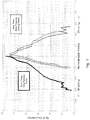
- Figure 1 is a sample histogram illustrating the distribution of fore/aft forces on front and rear tires of exemplary rear wheel drive vehicles driven on a simulated road course.
- the histogram is not meant to illustrate properties of a specific tire or specific car, but is presented here to illustrate some of the different forces exerted on front tires versus rear tires.
- the illustrated example shows forces on two different cars.
- the x-axis represents a ratio of the fore-aft force to the static front load of a tire.
- the negative numbers on the axis represent a braking force and the positive numbers represent a driving force.
- the y-axis represents the percentage of each occurrence.
- rear wheel drive vehicles often exert small braking forces on the front tires, and may occasionally exert larger braking forces on the front tires. However, as one would expect, rear wheel drive tires do not any exert driving force on the front tires.
- Figure 1 illustrates that rear wheel drive vehicles often exert small driving forces on the rear tires, and occasionally exert larger driving forces on the rear tires. Rear wheel drive vehicles may also exert small to medium braking forces on the rear tires.
- the histogram of Figure 1 is specific to a given simulated road course, it should be understood that while changes to the road course would affect the histogram, the general differences between front and rear tires would still hold.
- Peak Fx is the greatest longitudinal force on the slip ratio versus a longitudinal force (N) curve. Peak Fx is known by those skilled in the arts to correlate with traction performance.
- a tire as defined in claim 1 and a method of mounting a plurality of tires as defined in claim 6 are provided.
- the dependent claims define preferred and/or advantageous embodiments of the invention.
- a tire having an equatorial plane includes a first side and a second side defining a first rotation direction and a second rotation direction of the tire.
- the first rotation direction of the tire is a rotation of the tire in a counterclockwise direction when the tire is viewed from the first side
- the second rotation direction of the tire is a rotation of the tire in a clockwise direction when the tire is viewed from the first side.
- the tire further includes a carcass ply extending from a first bead portion to a second bead portion, and a circumferential tread disposed above a belt.
- At least one of the circumferential tread and the carcass ply causes the tire to exhibit a first tire performance when the tire is rotated in the first rotation direction, and a second tire performance that is different from the first tire performance when the tire is rotated in the second rotation direction.
- the tire performance is selected from the group consisting of braking, dry driving traction, wear performance, and snow traction performance.
- a tire having an equatorial plane in another embodiment, includes a first bead portion and a second bead portion.
- the tire further includes a first side and a second side defining a first mounting position and a second mounting position of the tire. In the first mounting position, the first side faces away from a longitudinal axis of a vehicle, and in the second mounting position, the second side faces away from a longitudinal axis of the vehicle.
- the tire further includes at least one carcass ply extending from the first bead portion to the second bead portion, and a circumferential belt disposed above the at least one carcass ply.
- the tire also includes a circumferential tread having a plurality of tread elements disposed above the circumferential belt.
- At least one of the at least one carcass ply and the plurality of tread elements causes the tire to exhibit a first on-vehicle lateral performance when in the first mounting position on a front axle of the vehicle and the second mounting position on a rear axle of the vehicle, and a second on-vehicle lateral performance when in the first mounting position on the rear axle of the vehicle and the second mounting position on the front axle of the vehicle.
- a method of mounting a plurality of tires on a vehicle having a front axle and a rear axle includes providing four tires, including a first tire, a second tire, a third tire, and a fourth tire.
- Each of the four tires has a first bead portion and a second bead portion, a first side, a second side, at least one carcass ply extending from the first bead portion to the second bead portion, a circumferential belt disposed above the at least one carcass ply, and a circumferential tread disposed above the circumferential belt.
- the first side of each of the four tires is substantially the same, and the second side of each of the four tires is substantially the same.
- the method further includes mounting the first tire on a first wheel, mounting the second tire on a second wheel, mounting the third tire on a third wheel, and mounting the fourth tire on a fourth wheel.
- the method also includes mounting the first wheel on a left end of a front axle of a vehicle, such that the first side of the first tire faces away from a longitudinal axis of the vehicle and such that the first tire exhibits a first performance.
- the method additionally includes mounting the second wheel on a right end of the front axle of the vehicle, such that the second side of the second tire faces away from the longitudinal axis of the vehicle and such that the second tire exhibits the first performance.
- the method further includes mounting the third wheel on a left end of a rear axle of the vehicle, such that the second side of the third tire faces away from the longitudinal axis of the vehicle and such that the third tire exhibits a second performance that is lower than the first performance.
- the method also includes mounting the fourth wheel on a right end of the rear axle of the vehicle, such that the first side of the fourth tire faces away from the longitudinal axis of the vehicle and such that the fourth tire exhibits the second performance.
- a method of mounting a plurality of tires on a vehicle having a front axle and a rear axle includes providing four tires, including a first tire, a second tire, a third tire, and a fourth tire.
- Each of the four tires has a first bead portion and a second bead portion, a first side, a second side, a carcass ply extending from the first bead portion to the second bead portion, a belt disposed above the carcass ply, and a circumferential tread disposed above the belt, wherein at least one of the circumferential tread and the carcass ply causes the tire to be reflectively asymmetric about an equatorial plane.
- the first side of each of the four tires is substantially the same, and the second side of each of the four tires is substantially the same. Likewise, the circumferential tread of each of the four tires is substantially the same.
- the method further includes mounting the first tire on a first wheel, mounting the second tire on a second wheel, mounting the third tire on a third wheel, and mounting the fourth tire on a fourth wheel.
- the method also includes mounting the first wheel on a left end of a front axle of a vehicle, such that the first side of the first tire faces away from a longitudinal axis of the vehicle.
- the method additionally includes mounting the second wheel on a right end of the front axle of the vehicle, such that the first side of the second tire faces away from the longitudinal axis of the vehicle.
- the method further includes mounting the third wheel on a left end of a rear axle of the vehicle, such that the second side of the third tire faces away from the longitudinal axis of the vehicle, and mounting the fourth wheel on a right end of the rear axle of the vehicle, such that the second side of the fourth tire faces away from the longitudinal axis of the vehicle.
- a method of mounting a plurality of tires on a vehicle having a front axle and a rear axle includes providing four tires, including a first tire, a second tire, a third tire, and a fourth tire.
- Each of the four tires has a first bead portion and a second bead portion, a first side, a second side, at least one carcass ply extending from the first bead portion to the second bead portion, a circumferential belt disposed above the at least one carcass ply, and a circumferential tread disposed above the circumferential belt.
- Each of the four tires has a circumferential tire design with one of a tread pattern and a carcass ply with discrete rotational asymmetry of the second order.
- the first side of each of the four tires is substantially the same, and the second side of each of the four tires is substantially the same.
- the circumferential tread of each of the four tires is substantially the same.
- the method further includes mounting the first tire on a first wheel, mounting the second tire on a second wheel, mounting the third tire on a third wheel, and mounting the fourth tire on a fourth wheel.
- the method also includes mounting the first wheel on a left end of a front axle of a vehicle, such that the first side of the first tire faces away from a longitudinal axis of the vehicle, and mounting the second wheel on a right end of the front axle of the vehicle, such that the second side of the second tire faces away from the longitudinal axis of the vehicle.
- the method additionally includes mounting the third wheel on a left end of a rear axle of the vehicle, such that the first side of the third tire faces away from the longitudinal axis of the vehicle, and mounting the fourth wheel on a right end of the rear axle of the vehicle, such that the second side of the fourth tire faces away from the longitudinal axis of the vehicle, thereby providing a first rotational direction on all tires that has a first performance on all tires.
- Axial or “axially” refer to a direction that is parallel to the axis of rotation of a tire.
- Bead refers to the part of the tire that contacts the wheel and defines a boundary of the sidewall.
- Carcass ply refers to a structural member that connects the bead to a tread, and may be continuous or discrete.
- “Circumferential” and “circumferentially” refer to a direction extending along the perimeter of the surface of the tread perpendicular to the axial direction.
- Equatorial plane refers to the plane that is perpendicular to the tire's axis of rotation and passes through the center of the tire.
- Ring and radially refer to a direction perpendicular to the axis of rotation of a tire.
- “Sidewall” refers to that portion of the tire between the tread and the bead.
- Thread refers to that portion of the tire that comes into contact with the road under normal inflation and load.
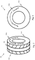
- Figures 2 and 3 show a perspective view and side view, respectively, of a schematic drawing of one embodiment of a tire 100 having an axle specific rolling direction.
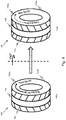
- Figure 4 shows a multi-perspective view of the tire 100 in a first orientation 110a and a second orientation 110b. The tire 100 is described in reference to all of these figures.
- the tire 100 includes a first and second bead portion (not shown), a first sidewall 120a, and a second sidewall 120b.
- the tire 100 has two rotation directions. When the tire is viewed from the second sidewall 120b (as shown in Figure 3 ), the first rotation direction of the tire 100 is in the clockwise direction and the second rotation direction of the tire 100 is in the counterclockwise direction.
- the tire 100 further includes at least one carcass ply (not shown) extending from the first bead portion to the second bead portion, a circumferential belt disposed above the carcass ply (not shown), and a circumferential tread 130 disposed above the belt.
- the circumferential tread 130 has a tread pattern shown schematically at 140.
- the tread pattern 140 has discrete rotational asymmetry of the second order, which causes the tire 100 to be directional. Therefore, when the tire 100 is in the first orientation 110a, the tread pattern 140 has a first appearance, and when the tire 100 is placed in the second orientation 110b, the reversed tread pattern 140 has a second appearance different from the first appearance.
- the asymmetry of the tread pattern may cause the tread to exhibit different properties when the tire 100 is rotated in the first direction versus the second direction.
- the tread pattern and the position and orientation of the carcass ply may be selected such that desirable properties for a front tire are exhibited when the tire 100 is rotated in the first direction, and desirable properties for a rear tire are exhibited when the tire 100 is rotated in the second direction.
- the tread pattern may be selected such that when the tire is rotated in the first rotation direction, the circumferential tread exhibits a first braking performance and a first driving traction performance, and when the tire is rotated in the second direction, the circumferential tread exhibits a second braking performance that is lower than the first braking performance and a second driving traction performance that is higher than the first driving traction performance.
- the rear wheel drive vehicles it may be more advantageous for the rear tires to exhibit higher driving traction performance.
- front wheel drive vehicles it may be more advantageous for the front tires to exhibit higher driving traction performance.
- the tread pattern may be selected such that the circumferential tread exhibits a first wear performance when rotated in the first direction, and a second wear performance different from the first wear performance when rotated in the second direction.
- first wear performance when rotated in the first direction
- second wear performance different from the first wear performance when rotated in the second direction.
- front wheel drive vehicles front tires tend to wear faster.
- rear wheel drive tires rear tires tend to wear faster.
- the tread pattern may be selected to reduce the discrepancy between the wear rates of front and rear tires.
- the tread pattern may be selected such that the circumferential tread exhibits a first snow traction performance when rotated in the first direction, and a second snow traction performance that is different from the first snow traction performance when rotated in the second direction.
- the tread pattern may also be selected such that other properties are affected by a change in rotation direction.
- the position and orientation of the carcass ply may be selected such that the carcass ply causes the tire to exhibit different properties according to the rotation direction. Such differences in carcass plies may not be readily observable from the exterior of the tire, but the tire would still exhibit asymmetric properties.
- the first rotation direction may be indicated as a Front Rotation Direction
- the second rotation direction may be indicated as a Rear Rotation Direction on one or more locations on the tire.
- a first indicia 150a is disposed on the first sidewall 120a and a second indicia 150b is disposed on the second sidewall 120b of the tire 100.
- Both the first indicia 150a and the second indicia 150b include an indicator designating the first rotation direction as a front tire rotation direction and the second rotation direction as a rear tire rotation direction. While the illustrated embodiment shows arrows with a written description, it should be understood that the indicia may take any form or size.
- Such indicia may be used to aid a person in mounting axle specific tires on a vehicle.
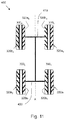
- the properties of the tire 100 may be selected so that four tires having substantially the same sidewalls, carcass plies, and circumferential tread may be mounted on a vehicle 200 in such a way that first and second tires 100 1 , 100 2 on a front axle 210 exhibit different properties than third and fourth tires 100 3 , 100 4 mounted on a rear axle 220.
- the first tire 100 1 is mounted on a first wheel (not shown)
- the second tire 100 2 is mounted on a second wheel (not shown)
- the third tire 100 3 is mounted on a third wheel (not shown)
- the fourth tire 100 4 is mounted on a fourth wheel (not shown).
- the first wheel and tire are mounted on a left end of the front axle 210 of a vehicle 200, such that a first sidewall 120 a1 of the first tire 100 1 faces outwards, ( i.e., away from a longitudinal axis A of the vehicle 200 ), and a second sidewall 120 b1 of the first tire 100 1 faces inwards ( i.e., towards the longitudinal axis A of the vehicle 200 ).
- the second wheel and tire are mounted on a right end of the front axle 210 of the vehicle 200, such that a first sidewall 120a 2 of the second tire 100 2 faces inwards, and a second sidewall 120b 2 of the second tire 100 2 faces outwards.
- the third wheel and tire are mounted on a left end of the rear axle 220 of the vehicle 200, such that a first sidewall 120a 3 of the third tire 100 3 faces inwards, and a second sidewall 120b 3 of the third tire 100 3 faces outwards.
- the fourth wheel and tire are mounted on a right end of the rear axle 220 of the vehicle 200, such that a first sidewall 120a 4 of the fourth tire 100 4 faces outwards, and a second sidewall 120b 4 of the fourth tire 100 4 faces inwards.
- tires may be mounted on the vehicle in any order, and that certain steps described above may be performed concurrently or in a different order.
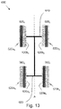
- the tires When servicing the vehicle, the tires may be rotated in the manner illustrated in Figure 6 , without having to dismount the tires from the wheels.
- the first wheel and tire are removed from the front axle 210 of the vehicle 200 and the fourth wheel and tire are removed from the rear axle 220 of the vehicle 200.
- the first wheel and tire are mounted on the right end of the rear axle 220 of the vehicle 200, such that the first sidewall 120a 1 of the first tire 100 1 faces outwards, and the second sidewall 120b 1 of the first tire 100 1 faces inwards.
- the fourth wheel and tire are mounted on the left end of the front axle 210 of the vehicle 200, such that a first sidewall 120a 4 of the fourth tire 100 4 faces outwards, and a second sidewall 120b 4 of the fourth tire 100 4 faces inwards.
- the second wheel and tire are removed from the front axle 210 of the vehicle 200 and the third wheel and tire are removed from the rear axle 220 of the vehicle 200.
- the second wheel and tire are mounted on the left end of the rear axle 220 of the vehicle 200, such that a first sidewall 120a 2 of the second tire 100 2 faces inwards, and a second sidewall 120b 2 of the second tire 100 2 faces outwards.
- the third wheel and tire are mounted on the right end of the front axle 210 of the vehicle 200, such that a first sidewall 120a 3 of the third tire 100 3 faces inwards, and a second sidewall 120b 3 of the third tire 100 3 faces outwards.
- Figures 2-6 illustrate bidirectional tires that exhibit desirable front tire characteristics when rotated in a first direction, and desirable rear tire characteristics when rotated in a second direction
- bidirectional tires may also be designed to exhibit desirable summer performance characteristics when rotated in a first direction, and desirable winter performance characteristics when rotated in a second direction.
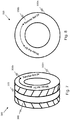
- Figures 7 and 8 show a perspective view and side view, respectively, of a schematic drawing of one embodiment of a tire 300 having a season specific rolling direction.
- Figure 9 shows a multi-perspective view of the tire 300 in a first orientation 310a and a second orientation 310b. The tire 300 is described in reference to all of these figures.
- the tire 300 includes a first and second bead portion (not shown), a first sidewall 320a, and a second sidewall 320b.
- the tire 300 has two rotation directions. When the tire is viewed from the second sidewall 320b (as shown in Figure 8 ), the first rotation direction of the tire 300 is in the clockwise direction and the second rotation direction of the tire 300 is in the counterclockwise direction.
- the tire 300 further includes at least one carcass ply (not shown) extending from the first bead portion to the second bead portion, a circumferential belt disposed above the carcass ply (not shown), and a circumferential tread 330 disposed above the belt.
- the circumferential tread 330 has a tread pattern shown schematically at 340.
- the tread pattern 340 has discrete rotational asymmetry of the second order, which causes the tire 300 to be directional. Therefore, when the tire 300 is in the first orientation 310a, the tread pattern 340 has a first appearance, and when the tire 300 is placed in the second orientation 310b, the reversed tread pattern 340 has a second appearance different from the first appearance.
- the asymmetry of the tread pattern may cause the tread to exhibit different properties when the tire 300 is rotated in the first direction versus the second direction.
- the tread pattern and the position and orientation of the carcass ply may be selected such that desirable properties for summer performance are exhibited when the tire 300 is rotated in the first direction, and desirable properties for winter performance are exhibited when the tire 300 is rotated in the second direction.
- the tread pattern may be selected such that the circumferential tread exhibits a first snow traction performance when rotated in the first direction, and a second snow traction performance that is different from the first snow traction performance when rotated in the second direction.
- the tread pattern may also be selected such that other properties are affected by a change in rotation direction.
- the tread pattern may be selected such that when the tire is rotated in the first rotation direction, the circumferential tread exhibits a first stopping distance performance, and when the tire is rotated in the second direction, the circumferential tread exhibits a second stopping distance performance that is lower than the first stopping performance. Stopping distance performance may be more important in summer, when vehicles tend to be driven at higher speeds.
- the tread pattern may be selected such that the circumferential tread exhibits a first wear performance when rotated in the first direction, and a second wear performance different from the first wear performance when rotated in the second direction.
- tires tend to wear slower in the winter when they are driven over snow.
- the tread pattern may be selected to reduce the discrepancy between the wear rates in summer and winter.
- the tread pattern may be selected such that the circumferential tread exhibits a first noise performance when rotated in the first direction, and a second noise performance different from the first noise performance when rotated in the second direction.
- tires tend to be quieter in the winter when they are driven over snow.
- the tread pattern may be selected to reduce the discrepancy between the tire noise in summer and winter.
- the position and orientation of the carcass ply may be selected such that the carcass ply causes the tire to exhibit different properties according to the rotation direction. Such differences in carcass plies may not be readily observable from the exterior of the tire, but the tire would still exhibit asymmetric properties.
- the first rotation direction may be indicated as a Summer Rotation Direction
- the second rotation direction may be indicated as a Winter Rotation Direction on one or more locations on the tire.
- a first indicia 350a is disposed on the first sidewall 320a
- a second indicia 350b is disposed on the second sidewall 320b of the tire 300.
- Both the first indicia 350a and the second indicia 350b include an indicator designating the first rotation direction as a summer rotation direction and the second rotation direction as a winter rotation direction. While the illustrated embodiment shows arrows with a written description, it should be understood that the indicia may take any form or size.
- Such indicia may be used to aid a person in mounting season specific tires on a vehicle.
- the properties of the tire 300 may be selected so that four tires having substantially the same sidewalls, carcass plies, and circumferential tread may be mounted on a vehicle 400 in such a way that all tires 300 1 , 300 2 , 300 3 , 300 4 exhibit desirable summer performance characteristics.
- the first tire 300 1 is mounted on a first wheel (not shown)
- the second tire 300 2 is mounted on a second wheel (not shown)
- the third tire 300 3 is mounted on a third wheel (not shown)
- the fourth tire 300 4 is mounted on a fourth wheel (not shown).
- the first wheel and tire are mounted on a left end of the front axle 410 of a vehicle 400, such that a first sidewall 320a 1 of the first tire 300 1 faces outwards, ( i.e., away from a longitudinal axis A of the vehicle 400 ), and a second sidewall 320b 1 of the first tire 300 1 faces inwards ( i.e., towards the longitudinal axis A of the vehicle 400 ).
- the second wheel and tire are mounted on a right end of the front axle 410 of the vehicle 400, such that a first sidewall 320a 2 of the second tire 300 2 faces inwards, and a second sidewall 320b 2 of the second tire 300 2 faces outwards.
- the third wheel and tire are mounted on a left end of the rear axle 420 of the vehicle 400, such that a first sidewall 320a 3 of the third tire 300 3 faces outwards, and a second sidewall 320b 3 of the third tire 300 3 faces inwards.
- the fourth wheel and tire are mounted on a right end of the rear axle 420 of the vehicle 400, such that a first sidewall 320a 4 of the fourth tire 300 4 faces inwards, and a second sidewall 320b 4 of the fourth tire 100 4 faces outwards.
- tires may be mounted on the vehicle in any order, and that certain steps described above may be performed concurrently or in a different order.
- the tires may be rotated in the manner illustrated in Figure 11 , without having to dismount the tires from the wheels.
- the first wheel and tire are removed from the front axle 410 of the vehicle 400 and the fourth wheel and tire are removed from the rear axle 420 of the vehicle 400.
- the first wheel and tire are mounted on the right end of the rear axle 420 of the vehicle 400, such that the first sidewall 320a 1 of the first tire 300 1 faces outwards, and the second sidewall 320b 1 of the first tire 300 1 faces inwards.
- the fourth wheel and tire are mounted on the left end of the front axle 410 of the vehicle 400, such that a first sidewall 320a 4 of the fourth tire 300 4 faces inwards, and a second sidewall 320b 4 of the fourth tire 100 4 faces outwards.
- the second wheel and tire are removed from the front axle 410 of the vehicle 400 and the third wheel and tire are removed from the rear axle 420 of the vehicle 400.
- the second wheel and tire are mounted on the left end of the rear axle 420 of the vehicle 400, such that a first sidewall 320a 2 of the second tire 300 2 faces inwards, and a second sidewall 320b 2 of the second tire 300 2 faces outwards.
- the third wheel and tire are mounted on the right end of the front axle 410 of the vehicle 400, such that a first sidewall 320a 3 of the third tire 300 3 faces outwards, and a second sidewall 320b 3 of the third tire 300 3 faces inwards.
- Figure 12 shows a multi-perspective view of another embodiment of a tire 500 in a first orientation 510a and a second orientation 510b.
- the tire 500 includes a first and second bead portion (not shown), a first sidewall 520a, and a second sidewall 520b.
- the first and second sidewall 520a,b define a first mounting position and a second mounting position of the tire, in that the first sidewall 520a faces outwards in the first mounting position, and the second sidewall faces 520b faces outwards in the second mounting position.
- the tire 500 further includes at least one carcass ply (not shown) extending from the first bead portion to the second bead portion, a circumferential belt disposed above the carcass ply (not shown), and a circumferential tread 530 disposed above the belt.
- the circumferential tread 530 has a tread pattern shown schematically at 540.
- the tread pattern 540 is asymmetric about the equatorial plane of the tire 500. Therefore, when the tire 500 is in the first orientation shown in Figure 4 , the tread pattern 540 has a first appearance, and when the tire 500 is rotated to the second orientation shown in Figure 7 , the reversed tread pattern 540 has a second appearance different from the first appearance.
- the asymmetry of the tread pattern may cause the tread to exhibit different properties when the tire 100 is mounted in the first mounting position versus the second mounting position.
- the tread pattern may be selected to account for first wear characteristics when a tire is mounted in the first position, and to account for second wear characteristics different from the first wear characteristics when the tire is mounted in the second position.
- the front and rear tires may have different cambers.
- the weight of the vehicle may be distributed different on the front and rear axles. These differences may cause the front tires to have different footprints from the rear tires.
- the tread patterns in the first and second mounting positions of the tires may be selected to account for these different footprints.
- the tread pattern may be selected such that the circumferential tread exhibits a first snow traction performance when mounted in the first position, and a second snow traction performance different from the first snow traction performance when mounted in the second position.
- the tread pattern may also be selected such that other properties are affected by a change in mounting position. For example, the front and rear tires of a vehicle may experience different lateral forces. The tread pattern may be selected to effectively manage these different lateral forces.
- the position and orientation of the carcass ply may be selected such that the carcass ply causes the tire to exhibit different properties according to the mounting position. Such differences in carcass plies may not be readily observable from the exterior of the tire, but the tire would still exhibit asymmetric properties.
- the tread pattern and the position and orientation of the carcass ply may be designed to account for the different forces that are exhibited on the front and rear tires. Such different forces may cause the front and rear tires to wear differently.
- the first mounting direction may be indicated as a Front Mounting Position
- the second rotation direction may be indicated as a Rear Mounting Position on one or more locations on the tire.
- a first indicia 550a is disposed on the first sidewall 520a and a second indicia 550b is disposed on the second sidewall 520b of the tire 500. While the illustrated embodiment shows indicia that includes a written description, it should be understood that the indicia may take any form or size.
- Such indicia may be used to aid a person in mounting axle specific tires on a vehicle.
- the properties of the tire 500 may be selected so that four tires having substantially the same sidewalls, carcass plies, and circumferential tread may be mounted on a vehicle 600 in such a way that first and second tires 500 1 , 500 2 on a front axle 610 exhibit different properties than third and fourth tires 500 3 , 500 4 mounted on a rear axle 620.
- the first tire 500 1 is mounted on a first wheel (not shown)
- the second tire 500 2 is mounted on a second wheel (not shown)
- the third tire 500 3 is mounted on a third wheel (not shown)
- the fourth tire 500 4 is mounted on a fourth wheel (not shown).
- the first wheel and tire are mounted on a left end of the front axle 610 of a vehicle 600, such that a first sidewall 520a 1 of the first tire 500 1 faces outwards, and a second sidewall 520b 1 of the first tire 500 1 faces inwards.
- the second wheel and tire are mounted on a right end of the front axle 610 of the vehicle 600, such that a first sidewall 520a 2 of the second tire 500 2 faces outwards, and a second sidewall 520b 2 of the second tire 500 2 faces inwards.
- the third wheel and tire are mounted on a left end of the rear axle 620 of the vehicle 600, such that a first sidewall 520a 3 of the third tire 500 3 faces inwards, and a second sidewall 520b 3 of the third tire 500 3 faces outwards.
- the fourth wheel and tire are mounted on a right end of the rear axle 620 of the vehicle 600, such that a first sidewall 520a 4 of the fourth tire 500 4 faces inwards, and a second sidewall 520b 4 of the fourth tire 500 4 faces outwards.
- tires may be mounted on the vehicle in any order, and that certain steps described above may be performed concurrently or in a different order.
- the tires When servicing the vehicle, the tires may be rotated in the manner illustrated in Figure 9 , without having to dismount the tires from the wheels.
- the first wheel and tire, and second wheel and tire are removed from the front axle 610 of the vehicle 600.
- the first wheel and tire are mounted on the right end of the front axle 620 of the vehicle 600, such that the first sidewall 520a 1 of the first tire 500 1 faces outwards, and the second sidewall 520b 1 of the first tire 500 1 faces inwards.
- the second wheel and tire are mounted on the left end of the front axle 610 of the vehicle 600, such that a first sidewall 520a 2 of the second tire 500 2 faces outwards, and a second sidewall 520b 2 of the second tire 500 2 faces inwards.
- the third wheel and tire, and fourth wheel and tire are removed from the rear axle 620 of the vehicle 600.
- the third wheel and tire are mounted on the right end of the rear axle 620 of the vehicle 600, such that a first sidewall 520a 3 of the third tire 500 3 faces inwards, and a second sidewall 520b 3 of the third tire 500 3 faces outwards.
- the fourth wheel and tire are mounted on the left end of the rear axle 620 of the vehicle 600, such that a first sidewall 520a 4 of the fourth tire 500 4 faces inwards, and a second sidewall 520b 4 of the fourth tire 500 4 faces outwards.
- directional tread elements may be selected for the tire that display first characteristics when rotated in a first direction, and second characteristics different from the first characteristics when rotated in a second direction opposite the first direction.
- Figures 15-19 illustrate examples of tread elements that exhibit different characteristics in different rolling directions. While each of these figures illustrate a single feature, it should be understood that tread elements may employ two or more of the illustrated features. For the sake of brevity the various combinations of features are not shown herein.
- Figure 15 is a profile view of one embodiment of a tread element 700 that exhibits first characteristics in a first rolling direction D 1 and second characteristics in a second rolling direction D 2 .
- the tread element 700 includes a first wall 710 and a second wall 720.
- the first wall 710 is disposed at a first angle ⁇ 1 with respect to the base 730 of a groove in the tire.
- the second wall 720 is disposed at a second angle ⁇ 2 with respect to the base 730 of a groove in the tire that is greater than the first angle ⁇ 1 .
- the top of the tread element 700 and the second wall 720 form a leading edge.
- the shallower angle ⁇ 1 of the first wall 710 causes lower edge pressure on the tread element 700 when the tire is rotated in the first direction D 1 compared to when the tire is rotated in the second direction D 2 . This effect is utilized to achieve directional performance of the lug related to traction, wear, noise and other tire performance characteristics.
- Figure 16 is a profile view of another embodiment of a tread element 800 that exhibits first characteristics in a first rolling direction D 1 and second characteristics in a second rolling direction D 2 .
- the tread element 800 includes a first wall 810 and a second wall 820.
- the tread element 800 includes a plurality of sipes 830 adjacent the second wall, and no sipes adjacent the first wall.
- the tread element may have sipes adjacent both wall, but a greater number of sipes adjacent the second wall.
- the top of the tread element 800 and the first wall 810 form a leading edge.
- the top of the tread element 800 and the second wall 820 form a leading edge, and the sipes 830 provide additional edges adjacent the leading edge. This effect is utilized to achieve directional performance of the lug related to traction, wear, noise and other tire performance characteristics.
- Figure 17 is a profile view of yet another embodiment of a tread element 900 that exhibits first characteristics in a first rolling direction D 1 and second characteristics in a second rolling direction D 2 .
- the tread element 900 includes a first wall 910 and a second wall 920.
- the tread element 900 includes a plurality of angled sipes 930.
- When the tire is rotated in the first direction D 1 the rolling surface provides a shear force on the top of the tread element 900 that causes the angled sipes 930 to open and provide additional edges.
- the rolling surface provides a shear force on the top of the tread element 900 that causes the angled sipes 930 to close, thereby eliminating the additional edges. This effect is utilized to achieve directional performance of the lug related to traction, wear, noise and other tire performance characteristics.
- Figure 18 is a profile view of still another embodiment of a tread element 1000 that exhibits first characteristics in a first rolling direction D 1 and second characteristics in a second rolling direction D 2 .
- the tread element 1000 includes a first wall 1010 and a second wall 1020.
- the tread element 1000 includes a plurality of ratchet-shaped sipes 1030, that may be referred to as three-dimensional (or 3D) sipes 1030.
- 3D three-dimensional
- the rolling surface When the tire is rotated in the second direction D 2 , the rolling surface provides a shear force on the top of the tread element 1000 that causes the ratchet-shaped sipes 1030 to close, thereby eliminating the additional edges. This effect is utilized to achieve directional performance of the lug related to traction, wear, noise and other tire performance characteristics.
- Figure 19 is a profile view of still another embodiment of a tread element 1100 that exhibits first characteristics in a first rolling direction D 1 and second characteristics in a second rolling direction D 2 .
- the tread element 1100 includes a first wall 1110 and a second wall 1120.
- the tread element 1100 includes an edge treatment.
- the edge treatment is a rounded chamfer 1130 extending from the second wall 1120 to a top surface of the tread element 1100.
- the rounded chamfer 1130 extending from the second wall 1120 causes lower edge pressure on the tread element 1100 when the tire is rotated in the second direction D 2 , compared to when the tire is rotated in the first direction D 1 . It should be understood that other edge treatments may also be employed, such as planar chamfers.
- the tread element 1100 may be a lug, bounded by a pair of grooves. Alternatively, the tread element 1100 may represent a portion of a lug, bounded by a pair of sipes.
- the rounded chamfer 1130 has a length that is substantially greater than its height. In one particular embodiment, the length is four times greater than the height. In another known embodiment, the length is two times greater than the height. In an alternative embodiment (not shown), the height is greater than or equal to the length.
- Figure 20 is a profile view of still another embodiment of a tread element 1200 that exhibits first characteristics in a first rolling direction D 1 and second characteristics in a second rolling direction D 2 .
- the tread element 1200 shows that multiple features may be encompassed in a single tread element.
- the tread element 1200 includes a first wall 1210, and an edge treatment such as a rounded chamfer 1130 extending from the second wall 1220 to a top surface of the tread element 1200.
- the tread element further includes ratchet shaped sipes 1240 that are disposed at an angle and proximal to the first wall 1210.
- any combination of the above embodiments may be included in a single tread element.
Landscapes
- Engineering & Computer Science (AREA)
- Mechanical Engineering (AREA)
- Tires In General (AREA)
Applications Claiming Priority (4)
| Application Number | Priority Date | Filing Date | Title |
|---|---|---|---|
| US201261739320P | 2012-12-19 | 2012-12-19 | |
| PCT/US2013/074038 WO2014099471A1 (en) | 2012-12-19 | 2013-12-10 | Tire with bi-directional performance |
| EP19190785.6A EP3590731B1 (de) | 2012-12-19 | 2013-12-10 | Reifen mit bidirektionaler leistung |
| EP13865777.0A EP2934918B1 (de) | 2012-12-19 | 2013-12-10 | Reifen mit bidirektionaler leistung |
Related Parent Applications (3)
| Application Number | Title | Priority Date | Filing Date |
|---|---|---|---|
| EP13865777.0A Division EP2934918B1 (de) | 2012-12-19 | 2013-12-10 | Reifen mit bidirektionaler leistung |
| EP19190785.6A Division EP3590731B1 (de) | 2012-12-19 | 2013-12-10 | Reifen mit bidirektionaler leistung |
| EP19190785.6A Division-Into EP3590731B1 (de) | 2012-12-19 | 2013-12-10 | Reifen mit bidirektionaler leistung |
Publications (2)
| Publication Number | Publication Date |
|---|---|
| EP3851296A1 true EP3851296A1 (de) | 2021-07-21 |
| EP3851296B1 EP3851296B1 (de) | 2024-10-16 |
Family
ID=50979033
Family Applications (3)
| Application Number | Title | Priority Date | Filing Date |
|---|---|---|---|
| EP13865777.0A Active EP2934918B1 (de) | 2012-12-19 | 2013-12-10 | Reifen mit bidirektionaler leistung |
| EP21161032.4A Active EP3851296B1 (de) | 2012-12-19 | 2013-12-10 | Reifen mit bidirektionaler leistung |
| EP19190785.6A Active EP3590731B1 (de) | 2012-12-19 | 2013-12-10 | Reifen mit bidirektionaler leistung |
Family Applications Before (1)
| Application Number | Title | Priority Date | Filing Date |
|---|---|---|---|
| EP13865777.0A Active EP2934918B1 (de) | 2012-12-19 | 2013-12-10 | Reifen mit bidirektionaler leistung |
Family Applications After (1)
| Application Number | Title | Priority Date | Filing Date |
|---|---|---|---|
| EP19190785.6A Active EP3590731B1 (de) | 2012-12-19 | 2013-12-10 | Reifen mit bidirektionaler leistung |
Country Status (8)
| Country | Link |
|---|---|
| US (3) | US20150336429A1 (de) |
| EP (3) | EP2934918B1 (de) |
| JP (2) | JP6141448B2 (de) |
| KR (1) | KR20150087855A (de) |
| CN (1) | CN104918794B (de) |
| BR (1) | BR112015014264A2 (de) |
| RU (1) | RU2583014C1 (de) |
| WO (1) | WO2014099471A1 (de) |
Families Citing this family (10)
| Publication number | Priority date | Publication date | Assignee | Title |
|---|---|---|---|---|
| US9949674B2 (en) | 2012-12-17 | 2018-04-24 | Abbott Point Of Care Inc. | Portable clinical analysis system for hematocrit measurement |
| US9952194B2 (en) | 2012-12-17 | 2018-04-24 | Abbott Point Of Care Inc. | Operation and verification of a portable clinical analysis system |
| US9885706B2 (en) | 2012-12-17 | 2018-02-06 | Abbott Point Of Care Inc. | Portable clinical analysis system for immunometric measurement |
| JP6693146B2 (ja) * | 2016-01-26 | 2020-05-13 | 住友ゴム工業株式会社 | タイヤ |
| FR3049901A1 (fr) * | 2016-04-08 | 2017-10-13 | Michelin & Cie | Bande de roulement a directionnalites differenciees pour un pneumatique pour vehicule lourd |
| FR3049900A1 (fr) * | 2016-04-08 | 2017-10-13 | Michelin & Cie | Bande de roulement a directionnalites differenciees pour un pneumatique pour vehicule lourd |
| CN109789736B (zh) * | 2016-09-27 | 2021-02-02 | 米其林企业总公司 | 轮胎胎面以及具有该胎面的轮胎 |
| CN109789735B (zh) * | 2016-09-27 | 2021-02-02 | 米其林企业总公司 | 轮胎胎面以及具有该胎面的轮胎 |
| JP7372550B2 (ja) * | 2020-04-14 | 2023-11-01 | 横浜ゴム株式会社 | タイヤ |
| FI4015249T3 (fi) * | 2020-12-16 | 2023-12-28 | Goodyear Tire & Rubber | Nastoilla varustettu talvirengas |
Citations (5)
| Publication number | Priority date | Publication date | Assignee | Title |
|---|---|---|---|---|
| EP0384182A1 (de) * | 1989-02-22 | 1990-08-29 | Compagnie Generale Des Etablissements Michelin-Michelin & Cie | Luftreifenlauffläche für Lastkraftwagen, deren zentrale Rippen mit schrägen Einschnitten ausgestattet sind |
| JPH02283505A (ja) * | 1989-04-26 | 1990-11-21 | Yokohama Rubber Co Ltd:The | 氷雪路用タイヤの装着方法 |
| US20090000713A1 (en) * | 2007-06-27 | 2009-01-01 | Bridgestone Firestone North American Tire, Llc | Tire including segmented sipes |
| WO2010063751A1 (fr) * | 2008-12-05 | 2010-06-10 | Societe De Technologie Michelin | Bande de roulement pourvue d'incisions. |
| EP2607105A1 (de) * | 2011-12-21 | 2013-06-26 | Continental Reifen Deutschland GmbH | Anordnung von Fahrzeugluftreifen an einem Fahrzeug |
Family Cites Families (84)
| Publication number | Priority date | Publication date | Assignee | Title |
|---|---|---|---|---|
| US3630077A (en) | 1967-02-06 | 1971-12-28 | Campagnie Generale Des Etablis | Tire covers |
| DE2355387A1 (de) | 1973-11-06 | 1975-05-15 | Uniroyal Ag | Fahrzeugluftreifen und verfahren zum bestimmen seines guenstigsten einbauzustandes |
| US3909906A (en) | 1974-03-08 | 1975-10-07 | Kenneth T Macmillan | Method of maintaining proper rotational characteristics of a radial tire |
| US4134362A (en) | 1977-01-16 | 1979-01-16 | Kustom Fit Manufacturing Co. | Apparatus for marking tire sidewalls |
| JPS5462283A (en) | 1977-10-28 | 1979-05-19 | Bridgestone Tire Co Ltd | Forming of mark indicator of tire and side wall |
| FR2461602A1 (fr) * | 1979-07-24 | 1981-02-06 | Michelin & Cie | Pneumatique destine a rouler sur la neige |
| US4319713A (en) * | 1981-01-05 | 1982-03-16 | Eagle-Picher Industries, Inc. | Stove blower control accessory |
| US4343342A (en) | 1981-03-25 | 1982-08-10 | The Firestone Tire & Rubber Company | Unified modular indicia marking for rubber articles |
| IT1175345B (it) | 1984-02-10 | 1987-07-01 | Pirelli | Pneumatico direzionale per autoveicoli |
| US4547139A (en) | 1984-12-17 | 1985-10-15 | The Goodyear Tire & Rubber Company | Tire mold |
| GB8505415D0 (en) | 1985-03-02 | 1985-04-03 | Sp Tyres Uk Ltd | Radial ply tyres |
| GB8505414D0 (en) * | 1985-03-02 | 1985-04-03 | Sp Tyres Uk Ltd | Wheel driven vehicles |
| GB8509003D0 (en) | 1985-04-09 | 1985-05-15 | Apsley Metals Ltd | Vehicle axle unit |
| GB2192842B (en) | 1986-06-13 | 1991-01-30 | Bridgestone Corp | Pneumatic tire |
| DE8707957U1 (de) * | 1987-06-04 | 1987-09-24 | Frisch, Anton, 6520 Worms | Kraftfahrzeugreifen |
| DE3815542A1 (de) | 1988-05-06 | 1989-11-16 | Stahlgruber Gruber & Co Otto | Geraet fuer das aufbringen von zierringen auf rotationssymmetrische gummigegenstaende, insbesondere die sichtbare oberflaeche von fahrzeugreifen |
| US4984616A (en) | 1989-05-25 | 1991-01-15 | The Goodyear Tire & Rubber Company | Front and rear tire tread patterns in a four-wheeled tire/vehicle system |
| JPH03139404A (ja) * | 1989-10-25 | 1991-06-13 | Bridgestone Corp | 空気入りタイヤ |
| JPH03143706A (ja) * | 1989-10-30 | 1991-06-19 | Yokohama Rubber Co Ltd:The | 空気入りタイヤの装着方法 |
| JPH03186405A (ja) * | 1989-12-14 | 1991-08-14 | Yokohama Rubber Co Ltd:The | 空気入りラジアルタイヤ |
| US5160383A (en) | 1990-09-17 | 1992-11-03 | The Goodyear Tire & Rubber Company | Tire having identification label affixed thereto |
| US5200008A (en) | 1991-02-07 | 1993-04-06 | Michelin Recherche Et Technique | Radial tire tread and method of mounting a tire with said tread |
| US5353854A (en) * | 1991-03-08 | 1994-10-11 | The Goodyear Tire & Rubber Company | Pneumatic tire having laterally connected lugs |
| US5264066A (en) | 1991-06-04 | 1993-11-23 | The Goodyear Tire & Rubber Company | Tire labeling apparatus |
| JP3072921B2 (ja) | 1991-07-04 | 2000-08-07 | 住友ゴム工業株式会社 | 空気入りタイヤ |
| US5230598A (en) * | 1992-01-28 | 1993-07-27 | Steves Jr Frank | Tire and wheel handling device |
| JP3172249B2 (ja) * | 1992-05-07 | 2001-06-04 | 株式会社ブリヂストン | 空気入りラジアルタイヤ |
| JP2519491Y2 (ja) | 1992-05-25 | 1996-12-04 | 住友ゴム工業株式会社 | ゴムタイヤ用表示ラベル及びそのラベル材 |
| JPH062864A (ja) | 1992-06-19 | 1994-01-11 | Matsushita Electric Ind Co Ltd | 調理家具組込式調理器 |
| JPH06286410A (ja) * | 1993-03-30 | 1994-10-11 | Bridgestone Corp | 二輪車用空気入りタイヤおよびタイヤ対 |
| DE4319713A1 (de) * | 1993-06-15 | 1994-12-22 | David Brannan | Reifen für ein Fahrzeug |
| JP3532995B2 (ja) * | 1995-03-10 | 2004-05-31 | 株式会社ブリヂストン | スタッドレス空気入りタイヤ |
| JP2989767B2 (ja) * | 1995-12-28 | 1999-12-13 | 住友ゴム工業株式会社 | 空気入りタイヤ |
| US5826319A (en) | 1996-05-29 | 1998-10-27 | Fori Automation, Inc. | Method for matchmounting an uniflated automobile tire on a wheel |
| JP3065941B2 (ja) | 1996-06-20 | 2000-07-17 | 三菱電線工業株式会社 | ニトリル基含有有機高分子物品の製造方法およびシール部材 |
| IT1289701B1 (it) | 1996-11-29 | 1998-10-16 | Bridgestone Firestone Tech | Metodo per la marcatura di un pneumatico |
| EP1019258A1 (de) * | 1997-10-04 | 2000-07-19 | Philip Blood | Reifen |
| WO1999048707A1 (en) | 1998-03-25 | 1999-09-30 | The Goodyear Tire & Rubber Company | Tire tread and mold for making treads |
| JP3064271B2 (ja) | 1998-11-20 | 2000-07-12 | 住友ゴム工業株式会社 | 自動車およびそれに用いる前輪用と後輪用の空気入りタイヤの組み合わせ |
| US7267148B2 (en) | 1999-08-10 | 2007-09-11 | Michelin Recherche Et Technique S.A. | Measurement of adherence between a vehicle wheel and the roadway |
| JP3363416B2 (ja) | 1999-12-21 | 2003-01-08 | 住友ゴム工業株式会社 | 空気入りタイヤ |
| US6609548B2 (en) * | 2000-05-11 | 2003-08-26 | Michelin Recherche Et Technique S.A. | Asymmetrical vehicle tire with balanced wet and dry performance |
| JP2002002233A (ja) * | 2000-06-22 | 2002-01-08 | Bridgestone Corp | 空気入りタイヤ |
| EP1179441B1 (de) | 2000-08-10 | 2006-02-08 | Société de Technologie Michelin | Luftreifen mit asymmetrischer Gürtelstruktur und Verfahren zum Aufziehen eines Reifens auf einem Fahrzeug |
| JP4598263B2 (ja) | 2000-12-08 | 2010-12-15 | 株式会社ブリヂストン | 空気入りタイヤの装着方法及び前輪用の空気入りタイヤ |
| EP1351830B1 (de) | 2001-01-10 | 2006-08-30 | Société de Technologie Michelin | Drehrichtungsgebundene lauffläche mit einschnitten von variabler neigung |
| JP2002274120A (ja) | 2001-03-15 | 2002-09-25 | Bridgestone Corp | 空気入りタイヤの装着方法及び前輪用の空気入りタイヤ |
| US6619563B2 (en) | 2001-05-14 | 2003-09-16 | Efc Systems, Inc. | Manifold block for flow control in coating applications |
| FR2828134A1 (fr) * | 2001-08-06 | 2003-02-07 | Michelin Soc Tech | Profil de surface des elements de sculpture d'une bande de roulement pour pneumatique |
| JP3542983B2 (ja) | 2001-08-21 | 2004-07-14 | 住友ゴム工業株式会社 | タイヤ及びその装着方法 |
| US6783188B2 (en) | 2001-10-09 | 2004-08-31 | The Yokohama Rubber Co., Ltd. | Method of fitting tire-and-wheel assembled body to axle |
| JP3723764B2 (ja) | 2001-11-27 | 2005-12-07 | 住友ゴム工業株式会社 | 空気入りタイヤ |
| US20030211273A1 (en) | 2002-05-10 | 2003-11-13 | Karen Perry | Tire identification label |
| EP1528988B1 (de) | 2002-08-02 | 2006-10-04 | Continental Teves AG & Co. oHG | Verfahren zur zuordnung von rädern eines kraftfahrzeugs zu der jeweiligen fahrzeugachse |
| JP4266600B2 (ja) * | 2002-08-30 | 2009-05-20 | 株式会社ブリヂストン | 非対称トレッドパターンを有するタイヤ |
| JP4428914B2 (ja) * | 2002-08-30 | 2010-03-10 | 株式会社ブリヂストン | 非対称トレッドパターンを有するタイヤおよびその装着方法 |
| DE60335740D1 (de) | 2002-12-02 | 2011-02-24 | Sumitomo Rubber Ind | Reifen mit anzeigemarkierung für die rotationsdauer |
| JP4107385B2 (ja) * | 2002-12-03 | 2008-06-25 | 横浜ゴム株式会社 | 空気入りタイヤ |
| JP4309139B2 (ja) | 2003-01-10 | 2009-08-05 | 横浜ゴム株式会社 | タイヤマーキングシステム |
| CN100475567C (zh) | 2003-03-25 | 2009-04-08 | 米其林技术公司 | 在施工机械上安装轮胎的方法以及相关的轮胎 |
| US20050224153A1 (en) | 2004-04-12 | 2005-10-13 | Al Speyer | Use of colored indicia on tires as a designator |
| JP4580387B2 (ja) | 2004-05-27 | 2010-11-10 | 株式会社ブリヂストン | 空気入りタイヤ |
| US7387144B2 (en) | 2005-02-25 | 2008-06-17 | Bridgestone Firestone North American Tire, Llc | Tire having a textured marking and method of making same |
| EP1859963B1 (de) | 2005-03-16 | 2010-04-21 | Bridgestone Corporation | Reifen |
| EP1918130A4 (de) * | 2005-08-23 | 2009-06-10 | Bridgestone Corp | Luftreifen |
| JP4800709B2 (ja) * | 2005-08-25 | 2011-10-26 | 株式会社ブリヂストン | 二輪車用空気入りタイヤ |
| USD556127S1 (en) * | 2005-08-31 | 2007-11-27 | Bridgestone Corporation | Pair of decorative surfaces for a tire sidewall |
| JP4841215B2 (ja) * | 2005-10-03 | 2011-12-21 | 株式会社ブリヂストン | 二輪車用空気入りタイヤ |
| US20070256771A1 (en) | 2006-05-08 | 2007-11-08 | Balogh George F | Tire having sidewall with integral colored marking composite |
| JP4862684B2 (ja) | 2006-05-30 | 2012-01-25 | 横浜ゴム株式会社 | タイヤ加硫用成形金型 |
| EP2039533B1 (de) * | 2006-07-06 | 2012-01-25 | Bridgestone Corporation | Luftreifen |
| JP4925803B2 (ja) | 2006-12-04 | 2012-05-09 | 株式会社ブリヂストン | タイヤ |
| JP4874082B2 (ja) | 2006-12-20 | 2012-02-08 | 株式会社ブリヂストン | タイヤ |
| US8215366B2 (en) | 2007-01-04 | 2012-07-10 | Immler Michael | Mounting device, and method for mounting and dismounting a vehicle tire on and from a rim |
| US7950426B2 (en) * | 2007-06-08 | 2011-05-31 | Bridgestone Americas Tire Operations, Llc | Tread blocks having reduced edge stiffness |
| JP4223064B2 (ja) * | 2007-06-12 | 2009-02-12 | 横浜ゴム株式会社 | 空気入りタイヤ |
| JP4217266B1 (ja) | 2007-08-07 | 2009-01-28 | 住友ゴム工業株式会社 | 空気入りタイヤ |
| JP5160345B2 (ja) | 2008-08-26 | 2013-03-13 | 東洋ゴム工業株式会社 | 空気入りタイヤ |
| JP4685919B2 (ja) * | 2008-12-08 | 2011-05-18 | 住友ゴム工業株式会社 | 空気入りタイヤ |
| JP5356285B2 (ja) * | 2010-03-09 | 2013-12-04 | 東洋ゴム工業株式会社 | 空気入りタイヤ |
| US9174495B2 (en) * | 2010-12-22 | 2015-11-03 | The Goodyear Tire & Rubber Company | Pneumatic tire with tread having sipes |
| JP5823153B2 (ja) * | 2011-04-08 | 2015-11-25 | 東洋ゴム工業株式会社 | 空気入りタイヤ |
| JP5973142B2 (ja) * | 2011-08-09 | 2016-08-23 | 東洋ゴム工業株式会社 | 車両のタイヤ装着構造 |
| CN202319755U (zh) * | 2011-12-06 | 2012-07-11 | 肇庆骏鸿实业有限公司 | 轮胎 |
-
2013
- 2013-12-10 WO PCT/US2013/074038 patent/WO2014099471A1/en not_active Ceased
- 2013-12-10 RU RU2015128492/11A patent/RU2583014C1/ru not_active IP Right Cessation
- 2013-12-10 CN CN201380066321.5A patent/CN104918794B/zh active Active
- 2013-12-10 EP EP13865777.0A patent/EP2934918B1/de active Active
- 2013-12-10 JP JP2015549457A patent/JP6141448B2/ja not_active Expired - Fee Related
- 2013-12-10 EP EP21161032.4A patent/EP3851296B1/de active Active
- 2013-12-10 BR BR112015014264A patent/BR112015014264A2/pt not_active IP Right Cessation
- 2013-12-10 EP EP19190785.6A patent/EP3590731B1/de active Active
- 2013-12-10 KR KR1020157016835A patent/KR20150087855A/ko not_active Ceased
- 2013-12-10 US US14/653,009 patent/US20150336429A1/en not_active Abandoned
-
2017
- 2017-03-13 JP JP2017047347A patent/JP2017124829A/ja not_active Withdrawn
-
2019
- 2019-06-21 US US16/448,134 patent/US12115818B2/en active Active
-
2024
- 2024-09-16 US US18/886,269 patent/US20250001807A1/en active Pending
Patent Citations (5)
| Publication number | Priority date | Publication date | Assignee | Title |
|---|---|---|---|---|
| EP0384182A1 (de) * | 1989-02-22 | 1990-08-29 | Compagnie Generale Des Etablissements Michelin-Michelin & Cie | Luftreifenlauffläche für Lastkraftwagen, deren zentrale Rippen mit schrägen Einschnitten ausgestattet sind |
| JPH02283505A (ja) * | 1989-04-26 | 1990-11-21 | Yokohama Rubber Co Ltd:The | 氷雪路用タイヤの装着方法 |
| US20090000713A1 (en) * | 2007-06-27 | 2009-01-01 | Bridgestone Firestone North American Tire, Llc | Tire including segmented sipes |
| WO2010063751A1 (fr) * | 2008-12-05 | 2010-06-10 | Societe De Technologie Michelin | Bande de roulement pourvue d'incisions. |
| EP2607105A1 (de) * | 2011-12-21 | 2013-06-26 | Continental Reifen Deutschland GmbH | Anordnung von Fahrzeugluftreifen an einem Fahrzeug |
Non-Patent Citations (1)
| Title |
|---|
| BRYAN A. GARNER: "A Dictionary of Modern Legal Usage", vol. 624, 1995 |
Also Published As
| Publication number | Publication date |
|---|---|
| EP2934918A1 (de) | 2015-10-28 |
| KR20150087855A (ko) | 2015-07-30 |
| US20190299720A1 (en) | 2019-10-03 |
| CN104918794B (zh) | 2017-06-13 |
| US20250001807A1 (en) | 2025-01-02 |
| RU2583014C1 (ru) | 2016-04-27 |
| JP2017124829A (ja) | 2017-07-20 |
| EP2934918B1 (de) | 2019-09-25 |
| EP3851296B1 (de) | 2024-10-16 |
| EP3590731A1 (de) | 2020-01-08 |
| EP2934918A4 (de) | 2017-01-18 |
| JP6141448B2 (ja) | 2017-06-07 |
| BR112015014264A2 (pt) | 2017-07-11 |
| WO2014099471A1 (en) | 2014-06-26 |
| CN104918794A (zh) | 2015-09-16 |
| JP2016505443A (ja) | 2016-02-25 |
| US20150336429A1 (en) | 2015-11-26 |
| US12115818B2 (en) | 2024-10-15 |
| EP3590731B1 (de) | 2021-04-14 |
Similar Documents
| Publication | Publication Date | Title |
|---|---|---|
| US20250001807A1 (en) | Tire with bi-directional performance | |
| EP2899041B1 (de) | Luftreifen | |
| CN104097459B (zh) | 充气轮胎 | |
| EP2781372A1 (de) | Radialluftreifen für pkw und anwendungsverfahren dafür | |
| EP3098089A1 (de) | Winterreifen | |
| EP2213482A1 (de) | Luftreifen | |
| JPWO2009038131A1 (ja) | 空気入りタイヤ | |
| CN102756617A (zh) | 充气轮胎 | |
| EP2248681A1 (de) | Spikeloser reifen | |
| US20190308465A1 (en) | Tyre | |
| US10232670B2 (en) | Pneumatic tire | |
| US20220118798A1 (en) | Tire | |
| EP1963111B1 (de) | Luftreifen mit asymmetrischem laufflächenprofil | |
| JP6013759B2 (ja) | 空気入りタイヤ | |
| JP6291430B2 (ja) | スタッドレスタイヤ | |
| KR102370655B1 (ko) | 타이어의 설계 방법 및 이를 이용하여 제조된 타이어 | |
| JP2022030010A (ja) | 重荷重用チューブレスタイヤ |
Legal Events
| Date | Code | Title | Description |
|---|---|---|---|
| PUAI | Public reference made under article 153(3) epc to a published international application that has entered the european phase |
Free format text: ORIGINAL CODE: 0009012 |
|
| STAA | Information on the status of an ep patent application or granted ep patent |
Free format text: STATUS: THE APPLICATION HAS BEEN PUBLISHED |
|
| AC | Divisional application: reference to earlier application |
Ref document number: 3590731 Country of ref document: EP Kind code of ref document: P Ref document number: 2934918 Country of ref document: EP Kind code of ref document: P |
|
| AK | Designated contracting states |
Kind code of ref document: A1 Designated state(s): AL AT BE BG CH CY CZ DE DK EE ES FI FR GB GR HR HU IE IS IT LI LT LU LV MC MK MT NL NO PL PT RO RS SE SI SK SM TR |
|
| STAA | Information on the status of an ep patent application or granted ep patent |
Free format text: STATUS: REQUEST FOR EXAMINATION WAS MADE |
|
| 17P | Request for examination filed |
Effective date: 20220119 |
|
| RBV | Designated contracting states (corrected) |
Designated state(s): AL AT BE BG CH CY CZ DE DK EE ES FI FR GB GR HR HU IE IS IT LI LT LU LV MC MK MT NL NO PL PT RO RS SE SI SK SM TR |
|
| STAA | Information on the status of an ep patent application or granted ep patent |
Free format text: STATUS: EXAMINATION IS IN PROGRESS |
|
| 17Q | First examination report despatched |
Effective date: 20220412 |
|
| GRAP | Despatch of communication of intention to grant a patent |
Free format text: ORIGINAL CODE: EPIDOSNIGR1 |
|
| STAA | Information on the status of an ep patent application or granted ep patent |
Free format text: STATUS: GRANT OF PATENT IS INTENDED |
|
| INTG | Intention to grant announced |
Effective date: 20230127 |
|
| GRAJ | Information related to disapproval of communication of intention to grant by the applicant or resumption of examination proceedings by the epo deleted |
Free format text: ORIGINAL CODE: EPIDOSDIGR1 |
|
| STAA | Information on the status of an ep patent application or granted ep patent |
Free format text: STATUS: EXAMINATION IS IN PROGRESS |
|
| INTC | Intention to grant announced (deleted) | ||
| GRAP | Despatch of communication of intention to grant a patent |
Free format text: ORIGINAL CODE: EPIDOSNIGR1 |
|
| STAA | Information on the status of an ep patent application or granted ep patent |
Free format text: STATUS: GRANT OF PATENT IS INTENDED |
|
| INTG | Intention to grant announced |
Effective date: 20240514 |
|
| P01 | Opt-out of the competence of the unified patent court (upc) registered |
Free format text: CASE NUMBER: APP_39549/2024 Effective date: 20240703 |
|
| GRAS | Grant fee paid |
Free format text: ORIGINAL CODE: EPIDOSNIGR3 |
|
| GRAA | (expected) grant |
Free format text: ORIGINAL CODE: 0009210 |
|
| STAA | Information on the status of an ep patent application or granted ep patent |
Free format text: STATUS: THE PATENT HAS BEEN GRANTED |
|
| AC | Divisional application: reference to earlier application |
Ref document number: 2934918 Country of ref document: EP Kind code of ref document: P Ref document number: 3590731 Country of ref document: EP Kind code of ref document: P |
|
| AK | Designated contracting states |
Kind code of ref document: B1 Designated state(s): AL AT BE BG CH CY CZ DE DK EE ES FI FR GB GR HR HU IE IS IT LI LT LU LV MC MK MT NL NO PL PT RO RS SE SI SK SM TR |
|
| REG | Reference to a national code |
Ref country code: GB Ref legal event code: FG4D |
|
| REG | Reference to a national code |
Ref country code: DE Ref legal event code: R096 Ref document number: 602013086208 Country of ref document: DE Ref country code: CH Ref legal event code: EP |
|
| REG | Reference to a national code |
Ref country code: IE Ref legal event code: FG4D |
|
| REG | Reference to a national code |
Ref country code: LT Ref legal event code: MG9D |
|
| REG | Reference to a national code |
Ref country code: NL Ref legal event code: MP Effective date: 20241016 |
|
| REG | Reference to a national code |
Ref country code: AT Ref legal event code: MK05 Ref document number: 1732655 Country of ref document: AT Kind code of ref document: T Effective date: 20241016 |
|
| PG25 | Lapsed in a contracting state [announced via postgrant information from national office to epo] |
Ref country code: NL Free format text: LAPSE BECAUSE OF FAILURE TO SUBMIT A TRANSLATION OF THE DESCRIPTION OR TO PAY THE FEE WITHIN THE PRESCRIBED TIME-LIMIT Effective date: 20241016 |
|
| PG25 | Lapsed in a contracting state [announced via postgrant information from national office to epo] |
Ref country code: NL Free format text: LAPSE BECAUSE OF FAILURE TO SUBMIT A TRANSLATION OF THE DESCRIPTION OR TO PAY THE FEE WITHIN THE PRESCRIBED TIME-LIMIT Effective date: 20241016 |
|
| PG25 | Lapsed in a contracting state [announced via postgrant information from national office to epo] |
Ref country code: PT Free format text: LAPSE BECAUSE OF FAILURE TO SUBMIT A TRANSLATION OF THE DESCRIPTION OR TO PAY THE FEE WITHIN THE PRESCRIBED TIME-LIMIT Effective date: 20250217 Ref country code: IS Free format text: LAPSE BECAUSE OF FAILURE TO SUBMIT A TRANSLATION OF THE DESCRIPTION OR TO PAY THE FEE WITHIN THE PRESCRIBED TIME-LIMIT Effective date: 20250216 Ref country code: HR Free format text: LAPSE BECAUSE OF FAILURE TO SUBMIT A TRANSLATION OF THE DESCRIPTION OR TO PAY THE FEE WITHIN THE PRESCRIBED TIME-LIMIT Effective date: 20241016 |
|
| PG25 | Lapsed in a contracting state [announced via postgrant information from national office to epo] |
Ref country code: FI Free format text: LAPSE BECAUSE OF FAILURE TO SUBMIT A TRANSLATION OF THE DESCRIPTION OR TO PAY THE FEE WITHIN THE PRESCRIBED TIME-LIMIT Effective date: 20241016 |
|
| PG25 | Lapsed in a contracting state [announced via postgrant information from national office to epo] |
Ref country code: BG Free format text: LAPSE BECAUSE OF FAILURE TO SUBMIT A TRANSLATION OF THE DESCRIPTION OR TO PAY THE FEE WITHIN THE PRESCRIBED TIME-LIMIT Effective date: 20241016 |
|
| PG25 | Lapsed in a contracting state [announced via postgrant information from national office to epo] |
Ref country code: ES Free format text: LAPSE BECAUSE OF FAILURE TO SUBMIT A TRANSLATION OF THE DESCRIPTION OR TO PAY THE FEE WITHIN THE PRESCRIBED TIME-LIMIT Effective date: 20241016 |
|
| PG25 | Lapsed in a contracting state [announced via postgrant information from national office to epo] |
Ref country code: NO Free format text: LAPSE BECAUSE OF FAILURE TO SUBMIT A TRANSLATION OF THE DESCRIPTION OR TO PAY THE FEE WITHIN THE PRESCRIBED TIME-LIMIT Effective date: 20250116 |
|
| PG25 | Lapsed in a contracting state [announced via postgrant information from national office to epo] |
Ref country code: AT Free format text: LAPSE BECAUSE OF FAILURE TO SUBMIT A TRANSLATION OF THE DESCRIPTION OR TO PAY THE FEE WITHIN THE PRESCRIBED TIME-LIMIT Effective date: 20241016 Ref country code: GR Free format text: LAPSE BECAUSE OF FAILURE TO SUBMIT A TRANSLATION OF THE DESCRIPTION OR TO PAY THE FEE WITHIN THE PRESCRIBED TIME-LIMIT Effective date: 20250117 Ref country code: LV Free format text: LAPSE BECAUSE OF FAILURE TO SUBMIT A TRANSLATION OF THE DESCRIPTION OR TO PAY THE FEE WITHIN THE PRESCRIBED TIME-LIMIT Effective date: 20241016 |
|
| PG25 | Lapsed in a contracting state [announced via postgrant information from national office to epo] |
Ref country code: PL Free format text: LAPSE BECAUSE OF FAILURE TO SUBMIT A TRANSLATION OF THE DESCRIPTION OR TO PAY THE FEE WITHIN THE PRESCRIBED TIME-LIMIT Effective date: 20241016 |
|
| PG25 | Lapsed in a contracting state [announced via postgrant information from national office to epo] |
Ref country code: RS Free format text: LAPSE BECAUSE OF FAILURE TO SUBMIT A TRANSLATION OF THE DESCRIPTION OR TO PAY THE FEE WITHIN THE PRESCRIBED TIME-LIMIT Effective date: 20250116 |
|
| PG25 | Lapsed in a contracting state [announced via postgrant information from national office to epo] |
Ref country code: SM Free format text: LAPSE BECAUSE OF FAILURE TO SUBMIT A TRANSLATION OF THE DESCRIPTION OR TO PAY THE FEE WITHIN THE PRESCRIBED TIME-LIMIT Effective date: 20241016 |
|
| PG25 | Lapsed in a contracting state [announced via postgrant information from national office to epo] |
Ref country code: MC Free format text: LAPSE BECAUSE OF FAILURE TO SUBMIT A TRANSLATION OF THE DESCRIPTION OR TO PAY THE FEE WITHIN THE PRESCRIBED TIME-LIMIT Effective date: 20241016 |
|
| PG25 | Lapsed in a contracting state [announced via postgrant information from national office to epo] |
Ref country code: DK Free format text: LAPSE BECAUSE OF FAILURE TO SUBMIT A TRANSLATION OF THE DESCRIPTION OR TO PAY THE FEE WITHIN THE PRESCRIBED TIME-LIMIT Effective date: 20241016 |
|
| REG | Reference to a national code |
Ref country code: DE Ref legal event code: R097 Ref document number: 602013086208 Country of ref document: DE |
|
| PG25 | Lapsed in a contracting state [announced via postgrant information from national office to epo] |
Ref country code: EE Free format text: LAPSE BECAUSE OF FAILURE TO SUBMIT A TRANSLATION OF THE DESCRIPTION OR TO PAY THE FEE WITHIN THE PRESCRIBED TIME-LIMIT Effective date: 20241016 |
|
| PG25 | Lapsed in a contracting state [announced via postgrant information from national office to epo] |
Ref country code: RO Free format text: LAPSE BECAUSE OF FAILURE TO SUBMIT A TRANSLATION OF THE DESCRIPTION OR TO PAY THE FEE WITHIN THE PRESCRIBED TIME-LIMIT Effective date: 20241016 |
|
| PG25 | Lapsed in a contracting state [announced via postgrant information from national office to epo] |
Ref country code: SK Free format text: LAPSE BECAUSE OF FAILURE TO SUBMIT A TRANSLATION OF THE DESCRIPTION OR TO PAY THE FEE WITHIN THE PRESCRIBED TIME-LIMIT Effective date: 20241016 |
|
| PG25 | Lapsed in a contracting state [announced via postgrant information from national office to epo] |
Ref country code: CZ Free format text: LAPSE BECAUSE OF FAILURE TO SUBMIT A TRANSLATION OF THE DESCRIPTION OR TO PAY THE FEE WITHIN THE PRESCRIBED TIME-LIMIT Effective date: 20241016 |
|
| PG25 | Lapsed in a contracting state [announced via postgrant information from national office to epo] |
Ref country code: IT Free format text: LAPSE BECAUSE OF FAILURE TO SUBMIT A TRANSLATION OF THE DESCRIPTION OR TO PAY THE FEE WITHIN THE PRESCRIBED TIME-LIMIT Effective date: 20241016 |
|
| REG | Reference to a national code |
Ref country code: CH Ref legal event code: PL |
|
| PG25 | Lapsed in a contracting state [announced via postgrant information from national office to epo] |
Ref country code: LU Free format text: LAPSE BECAUSE OF NON-PAYMENT OF DUE FEES Effective date: 20241210 |
|
| PLBE | No opposition filed within time limit |
Free format text: ORIGINAL CODE: 0009261 |
|
| STAA | Information on the status of an ep patent application or granted ep patent |
Free format text: STATUS: NO OPPOSITION FILED WITHIN TIME LIMIT |
|
| PG25 | Lapsed in a contracting state [announced via postgrant information from national office to epo] |
Ref country code: SE Free format text: LAPSE BECAUSE OF FAILURE TO SUBMIT A TRANSLATION OF THE DESCRIPTION OR TO PAY THE FEE WITHIN THE PRESCRIBED TIME-LIMIT Effective date: 20241016 |
|
| 26N | No opposition filed |
Effective date: 20250717 |
|
| GBPC | Gb: european patent ceased through non-payment of renewal fee |
Effective date: 20250116 |
|
| REG | Reference to a national code |
Ref country code: BE Ref legal event code: MM Effective date: 20241231 |
|
| PG25 | Lapsed in a contracting state [announced via postgrant information from national office to epo] |
Ref country code: GB Free format text: LAPSE BECAUSE OF NON-PAYMENT OF DUE FEES Effective date: 20250116 Ref country code: BE Free format text: LAPSE BECAUSE OF NON-PAYMENT OF DUE FEES Effective date: 20241231 |
|
| PG25 | Lapsed in a contracting state [announced via postgrant information from national office to epo] |
Ref country code: CH Free format text: LAPSE BECAUSE OF NON-PAYMENT OF DUE FEES Effective date: 20241231 |
|
| PG25 | Lapsed in a contracting state [announced via postgrant information from national office to epo] |
Ref country code: IE Free format text: LAPSE BECAUSE OF NON-PAYMENT OF DUE FEES Effective date: 20241210 |
|
| PGFP | Annual fee paid to national office [announced via postgrant information from national office to epo] |
Ref country code: DE Payment date: 20251126 Year of fee payment: 13 |
|
| PGFP | Annual fee paid to national office [announced via postgrant information from national office to epo] |
Ref country code: FR Payment date: 20251119 Year of fee payment: 13 |