EP3922876A1 - Composant coulissant - Google Patents
Composant coulissant Download PDFInfo
- Publication number
- EP3922876A1 EP3922876A1 EP20753172.4A EP20753172A EP3922876A1 EP 3922876 A1 EP3922876 A1 EP 3922876A1 EP 20753172 A EP20753172 A EP 20753172A EP 3922876 A1 EP3922876 A1 EP 3922876A1
- Authority
- EP
- European Patent Office
- Prior art keywords
- groove portion
- dynamic pressure
- pressure generating
- rayleigh step
- generating mechanism
- Prior art date
- Legal status (The legal status is an assumption and is not a legal conclusion. Google has not performed a legal analysis and makes no representation as to the accuracy of the status listed.)
- Granted
Links
Images






Classifications
-
- F—MECHANICAL ENGINEERING; LIGHTING; HEATING; WEAPONS; BLASTING
- F16—ENGINEERING ELEMENTS AND UNITS; GENERAL MEASURES FOR PRODUCING AND MAINTAINING EFFECTIVE FUNCTIONING OF MACHINES OR INSTALLATIONS; THERMAL INSULATION IN GENERAL
- F16J—PISTONS; CYLINDERS; SEALINGS
- F16J15/00—Sealings
- F16J15/16—Sealings between relatively-moving surfaces
- F16J15/34—Sealings between relatively-moving surfaces with slip-ring pressed against a more or less radial face on one member
- F16J15/3404—Sealings between relatively-moving surfaces with slip-ring pressed against a more or less radial face on one member and characterised by parts or details relating to lubrication, cooling or venting of the seal
- F16J15/3408—Sealings between relatively-moving surfaces with slip-ring pressed against a more or less radial face on one member and characterised by parts or details relating to lubrication, cooling or venting of the seal at least one ring having an uneven slipping surface
- F16J15/3412—Sealings between relatively-moving surfaces with slip-ring pressed against a more or less radial face on one member and characterised by parts or details relating to lubrication, cooling or venting of the seal at least one ring having an uneven slipping surface with cavities
-
- F—MECHANICAL ENGINEERING; LIGHTING; HEATING; WEAPONS; BLASTING
- F16—ENGINEERING ELEMENTS AND UNITS; GENERAL MEASURES FOR PRODUCING AND MAINTAINING EFFECTIVE FUNCTIONING OF MACHINES OR INSTALLATIONS; THERMAL INSULATION IN GENERAL
- F16C—SHAFTS; FLEXIBLE SHAFTS; ELEMENTS OR CRANKSHAFT MECHANISMS; ROTARY BODIES OTHER THAN GEARING ELEMENTS; BEARINGS
- F16C17/00—Sliding-contact bearings for exclusively rotary movement
- F16C17/04—Sliding-contact bearings for exclusively rotary movement for axial load only
-
- F—MECHANICAL ENGINEERING; LIGHTING; HEATING; WEAPONS; BLASTING
- F16—ENGINEERING ELEMENTS AND UNITS; GENERAL MEASURES FOR PRODUCING AND MAINTAINING EFFECTIVE FUNCTIONING OF MACHINES OR INSTALLATIONS; THERMAL INSULATION IN GENERAL
- F16C—SHAFTS; FLEXIBLE SHAFTS; ELEMENTS OR CRANKSHAFT MECHANISMS; ROTARY BODIES OTHER THAN GEARING ELEMENTS; BEARINGS
- F16C17/00—Sliding-contact bearings for exclusively rotary movement
- F16C17/04—Sliding-contact bearings for exclusively rotary movement for axial load only
- F16C17/045—Sliding-contact bearings for exclusively rotary movement for axial load only with grooves in the bearing surface to generate hydrodynamic pressure, e.g. spiral groove thrust bearings
-
- F—MECHANICAL ENGINEERING; LIGHTING; HEATING; WEAPONS; BLASTING
- F16—ENGINEERING ELEMENTS AND UNITS; GENERAL MEASURES FOR PRODUCING AND MAINTAINING EFFECTIVE FUNCTIONING OF MACHINES OR INSTALLATIONS; THERMAL INSULATION IN GENERAL
- F16C—SHAFTS; FLEXIBLE SHAFTS; ELEMENTS OR CRANKSHAFT MECHANISMS; ROTARY BODIES OTHER THAN GEARING ELEMENTS; BEARINGS
- F16C33/00—Parts of bearings; Special methods for making bearings or parts thereof
- F16C33/02—Parts of sliding-contact bearings
- F16C33/04—Brasses; Bushes; Linings
- F16C33/06—Sliding surface mainly made of metal
- F16C33/10—Construction relative to lubrication
- F16C33/1025—Construction relative to lubrication with liquid, e.g. oil, as lubricant
- F16C33/106—Details of distribution or circulation inside the bearings, e.g. details of the bearing surfaces to affect flow or pressure of the liquid
-
- F—MECHANICAL ENGINEERING; LIGHTING; HEATING; WEAPONS; BLASTING
- F16—ENGINEERING ELEMENTS AND UNITS; GENERAL MEASURES FOR PRODUCING AND MAINTAINING EFFECTIVE FUNCTIONING OF MACHINES OR INSTALLATIONS; THERMAL INSULATION IN GENERAL
- F16C—SHAFTS; FLEXIBLE SHAFTS; ELEMENTS OR CRANKSHAFT MECHANISMS; ROTARY BODIES OTHER THAN GEARING ELEMENTS; BEARINGS
- F16C33/00—Parts of bearings; Special methods for making bearings or parts thereof
- F16C33/02—Parts of sliding-contact bearings
- F16C33/04—Brasses; Bushes; Linings
- F16C33/06—Sliding surface mainly made of metal
- F16C33/10—Construction relative to lubrication
- F16C33/1025—Construction relative to lubrication with liquid, e.g. oil, as lubricant
- F16C33/106—Details of distribution or circulation inside the bearings, e.g. details of the bearing surfaces to affect flow or pressure of the liquid
- F16C33/107—Grooves for generating pressure
-
- F—MECHANICAL ENGINEERING; LIGHTING; HEATING; WEAPONS; BLASTING
- F16—ENGINEERING ELEMENTS AND UNITS; GENERAL MEASURES FOR PRODUCING AND MAINTAINING EFFECTIVE FUNCTIONING OF MACHINES OR INSTALLATIONS; THERMAL INSULATION IN GENERAL
- F16C—SHAFTS; FLEXIBLE SHAFTS; ELEMENTS OR CRANKSHAFT MECHANISMS; ROTARY BODIES OTHER THAN GEARING ELEMENTS; BEARINGS
- F16C33/00—Parts of bearings; Special methods for making bearings or parts thereof
- F16C33/72—Sealings
- F16C33/74—Sealings of sliding-contact bearings
-
- F—MECHANICAL ENGINEERING; LIGHTING; HEATING; WEAPONS; BLASTING
- F16—ENGINEERING ELEMENTS AND UNITS; GENERAL MEASURES FOR PRODUCING AND MAINTAINING EFFECTIVE FUNCTIONING OF MACHINES OR INSTALLATIONS; THERMAL INSULATION IN GENERAL
- F16J—PISTONS; CYLINDERS; SEALINGS
- F16J15/00—Sealings
- F16J15/16—Sealings between relatively-moving surfaces
- F16J15/34—Sealings between relatively-moving surfaces with slip-ring pressed against a more or less radial face on one member
Definitions
- the present invention relates to a sliding component that is subjected to relative rotation, for example, a sliding component used in a seal device that seals a rotating shaft of a rotary machine in an automobile, a general industrial machine, or other sealing fields, or a sliding component used in a bearing of an automobile, a general industrial machine, or a machine in other bearing fields.
- a mechanical seal including a pair of sliding components which have an annular shape and rotate relative to each other to cause sliding surfaces to slide against each other.
- the sliding surface of the sliding component is provided with a positive pressure generating groove communicating with an outer diameter side which is a sealed liquid side of a high pressure, and having a closed one end in the sliding surface. Accordingly, when the sliding components rotate relative to each other, a positive pressure is generated in the positive pressure generating groove to separate the sliding surfaces from each other, and the sealed liquid is introduced into the positive pressure generating groove from the outer diameter side to be held therein. Therefore, the lubricity is improved, and the friction is reduced.
- the mechanical seal is required to satisfy a condition such as "sealing" in addition to "lubrication".
- a condition such as "sealing" in addition to "lubrication”.
- one sliding component is provided with a Rayleigh step and a reverse Rayleigh step that communicate with a sealed liquid side. Accordingly, when sliding components rotate relative to each other, a positive pressure is generated between sliding surfaces by the Rayleigh step, to separate the sliding surfaces from each other, and the Rayleigh step holds a sealed liquid. Therefore, the lubricity is improved.
- the sealed liquid of a high pressure which has flowed out from the Rayleigh step to a gap between the sliding surfaces can be suctioned into the reverse Rayleigh step.
- the sealed liquid between a pair of the sliding components is prevented from leaking to the leakage side, so that the sealability is improved.
- Patent Citation 1 WO 2012/046749 A (pages 14 to 16 and FIG. 1 )
- Patent Citation 1 since a structure where the reverse Rayleigh step causes the sealed liquid to return to the sealed liquid side is adopted, the sealed liquid is not supplied to the leakage side in the gap between the sliding surfaces, and there is a portion which has no contribution to lubricity, which is a problem. Therefore, sliding components having higher lubricity are required.
- the present invention has been made in view of such a problem, and an object of the present invention is to provide a sliding component that supplies a sealed fluid to a leakage side in a gap between sliding surfaces to exhibit high lubricity and has a small leakage of the sealed fluid.
- a sliding component that has an annular shape and is disposed in a place where relative rotation is performed in a rotary machine, including a plurality of dynamic pressure generating mechanisms, in which the plurality of dynamic pressure generating mechanisms are provided in a sliding surface of the sliding component, each of the dynamic pressure generating mechanisms including a deep groove portion that communicates with a leakage side, and at least one shallow groove portion that communicates with the deep groove portion and extends in a circumferential direction. the shallow groove portion being shallower than the deep groove portion.
- the deep groove portion has a deep groove depth and a large volume, so that a large amount of the sealed fluid supplied to the leakage side of the sliding surface is recovered, and the sealed fluid flows out from the shallow groove portion to a gap between sliding surfaces. Therefore, lubricity can be improved over a wide area of the sliding surface.
- the sealed fluid is recovered by the deep groove portion communicating with the leakage side, and the recovered sealed fluid flows out from the shallow groove portion to the gap between the sliding surfaces to partly return to a sealed fluid side in a radial direction, the amount of the sealed fluid leaking to the leakage side is small.
- the deep groove portion extends in a radial direction. According to this preferable configuration, the sealed fluid can be held in the deep groove portion without being affected by dynamic pressure.
- a step in a depth direction is formed in a communication part between the shallow groove portion and the deep groove portion. According to this preferable configuration, the sealed fluid can be held in the deep groove portion without being affected by dynamic pressure.
- each of the plurality of dynamic pressure generating mechanisms includes a first shallow groove portion and a second shallow groove portion extend from each of the deep groove portions to both sides in the circumferential direction.
- the shallow groove portion which is disposed on one side in the circumferential direction of the deep groove portion can be used as a shallow groove portion for generating dynamic pressure. Therefore, the shallow groove portions can be used without being limited by the relative rotational direction of the sliding component.
- the plurality of dynamic pressure generating mechanisms includes a first dynamic pressure generating mechanism and a second dynamic pressure generating mechanism adjacent to each other in the circumferential direction, the first shallow groove portion of the first dynamic pressure generating mechanism is adjacent, in the circumferential direction, to the second shallow groove portion of the second dynamic pressure generating mechanism.
- the sealed fluid which is supplied from the one shallow groove portion of the dynamic pressure generating mechanism to the gap between the sliding surfaces to tend to move the leakage side can be recovered by the other shallow groove portion of the dynamic pressure generating mechanism adjacent thereto.
- the deep groove portion communicates with an inner diameter side of the sliding component. According to this preferable configuration, the sealed fluid which has been supplied from the shallow groove portion to the gap between the sliding surfaces can return to the sealed fluid side due to centrifugal force, and the sealed fluid is easily held in the deep groove portion due to centrifugal force.
- the sliding surface of the sliding component may be provided with a specific dynamic pressure generating mechanism that is disposed on a sealed fluid side with respect to the dynamic pressure generating mechanism and is independent of the dynamic pressure generating mechanism.
- a specific dynamic pressure generating mechanism that is disposed on a sealed fluid side with respect to the dynamic pressure generating mechanism and is independent of the dynamic pressure generating mechanism.
- the fact that the shallow groove portion of the sliding component according to the present invention extends in the circumferential direction means that the shallow groove portion may extend with at least a component in the circumferential direction, preferably, may extend such that the component along the circumferential direction is larger than the component in the radial direction.
- the fact that the deep groove portion extends in the radial direction means that the deep groove portion may extend with at least a component in the radial direction, preferably, may extend such that the component along the radial direction is larger than the component in the circumferential direction.
- the sealed fluid may be a liquid, or have a mist form in which a liquid and a gas are mixed.
- a sliding component according to a first embodiment of the present invention will be described with reference to FIGS. 1 to 5 .
- a mode in which the sliding component is a mechanical seal will be described as an example.
- a description will be given based on the premise that an outer diameter side of the sliding component forming the mechanical seal is a sealed liquid side (i.e., high-pressure side) as a sealed fluid side and an inner diameter side is an atmosphere side (i.e., low-pressure side) as a leakage side.
- dots may be added to a groove and the like formed in a sliding surface.
- a mechanical seal for a general industrial machine illustrated in FIG. 1 is an inside mechanical seal that seals a sealed liquid F which tends to leak from an outer diameter side of sliding surfaces toward an inner diameter side, and mainly includes a rotating seal ring 20 which is a sliding component that has an annular shape and is provided on a rotating shaft 1 with a sleeve 2 interposed therebetween, to be rotatable together with the rotating shaft 1, and a stationary seal ring 10 that has an annular shape and is a sliding component which is provided on a seal cover 5 fixed to a housing 4 of a mounted apparatus, to not be rotated but be movable in an axial direction.
- a rotating seal ring 20 which is a sliding component that has an annular shape and is provided on a rotating shaft 1 with a sleeve 2 interposed therebetween, to be rotatable together with the rotating shaft 1, and a stationary seal ring 10 that has an annular shape and is a sliding component which is provided on a seal cover 5 fixed to a housing 4 of
- the stationary seal ring 10 is biased in the axial direction by a bellows 7, so that a sliding surface 11 of the stationary seal ring 10 and a sliding surface 21 of the rotating seal ring 20 slide against each other in close contact with each other.
- the sliding surface 21 of the rotating seal ring 20 is a flat surface, and a recessed portion is not provided in the flat surface.
- the stationary seal ring 10 and the rotating seal ring 20 are representatively made of SiC (as an example of hard material) or a combination of SiC (as the example of hard material) and carbon (as an example of soft material); the sliding material is not limited thereto, and any type of sliding material is applicable as long as the sliding material is used as a sliding material for a mechanical seal.
- the SiC there are materials consisting of different components and compositions of two or more phases including a sintered body in which boron, aluminum, carbon, or the like is used as a sintering additive, for example, reaction-sintered SiC, SiC-TiC, SiC-TiN, and the like consisting of Sic or SiC and Si in which graphite particles are dispersed.
- a sintered body in which boron, aluminum, carbon, or the like is used as a sintering additive
- reaction-sintered SiC, SiC-TiC, SiC-TiN, and the like consisting of Sic or SiC and Si in which graphite particles are dispersed.
- the carbon resin molded carbon, sintered carbon, and the like carbon including carbon in which a carbonaceous material and a graphite material are mixed can be used.
- metallic materials, resin materials, surface modifiers (such as coating materials), composite materials, or the like are also applicable.
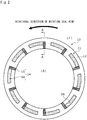
- the rotating seal ring 20 slides relative to the stationary seal ring 10 as indicated by an arrow, and a plurality of dynamic pressure generating mechanisms 14 are evenly provided in the sliding surface 11 of the stationary seal ring 10 in a circumferential direction of the stationary seal ring 10.
- a portion of the sliding surface 11 other than the dynamic pressure generating mechanisms 14 is a land 12 forming a flat surface.
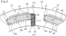
- FIGS. 2 to 4 an outline of the dynamic pressure generating mechanism 14 will be described based on FIGS. 2 to 4 .
- a description will be given based on the premise that when the stationary seal ring 10 and the rotating seal ring 20 rotate relative to each other, the left side of the drawing sheet of FIG. 4 is a downstream side of the sealed liquid F flowing in a Rayleigh step 9A to be described later, and the right side of the drawing sheet of FIG. 4 is an upstream side of the sealed liquid F flowing in the Rayleigh step 9A.
- the dynamic pressure generating mechanism 14 includes a liquid guide groove portion 15 as a deep groove portion that communicates with the atmosphere side and extends in an outer diameter direction, and the Rayleigh step 9A as a shallow groove portion that extends concentrically with the stationary seal ring 10 from an outer diameter side end portion of the liquid guide groove portion 15 toward the downstream side in the circumferential direction.
- the dynamic pressure generating mechanism 14 has an inverted L shape formed by the liquid guide groove portion 15 and the Rayleigh step 9A, when seen in a direction orthogonal to the sliding surface 11.
- the liquid guide groove portion 15 of the first embodiment extends in a radial direction to be orthogonal to an axis of the stationary seal ring 10.
- the liquid guide groove portion 15 and the Rayleigh step 9A communicate with each other, and a step 18 in a depth direction is formed in a communication part.
- a wall portion 9a orthogonal to a rotational direction is formed in an end portion on the downstream side of the Rayleigh step 9A.
- the wall portion 9a is not limited to being orthogonal to the rotational direction, for example, may be inclined with respect to the rotational direction or may be formed in a step shape.
- a depth dimension L10 of the liquid guide groove portion 15 is larger than a depth dimension L20 of the Rayleigh step 9A (L10 > L20).
- the depth dimension L10 of the liquid guide groove portion 15 is 100 ⁇ m
- the depth dimension L20 of the Rayleigh step 9A is 5 ⁇ m.
- the step 18 in the depth direction is formed between the liquid guide groove portion 15 and the Rayleigh step 9A by a side surface on the downstream side of the liquid guide groove portion 15 and a bottom surface of the Rayleigh step 9A.
- the depth dimensions of the liquid guide groove portion 15 is larger than the depth dimension of the Rayleigh step 9A
- the depth dimensions of the liquid guide groove portion 15 and the Rayleigh step 9A can be freely changed, and it is preferable that the dimension L10 is five times or more the dimension L20.
- the bottom surface of the Rayleigh step 9A is a flat surface and is formed in parallel to the land 12; however, the flat surface is not prevented from being provided with a fine recessed portion or being formed to be inclined with respect to the land 12.
- each of two arc-shaped surfaces of the Rayleigh step 9A is orthogonal to the bottom surface of the Rayleigh step 9A, the two arc-shaped surfaces extending in the circumferential direction.
- a bottom surface of the liquid guide groove portion 15 is a flat surface and is formed in parallel to the land 12; however, the flat surface is not prevented from being provided with a fine recessed portion or being formed to be inclined with respect to the land 12.
- each of two flat surfaces of the liquid guide groove portion 15 is orthogonal to the bottom surface of the liquid guide groove portion 15, the two flat surfaces extending in the radial direction.
- the pressure is the highest in the vicinity of the wall portion 9a which is the end portion on the downstream side of the Rayleigh step 9A, so that the low-pressure side fluid A flows out from the vicinity of the wall portion 9a to the periphery thereof as indicated by an arrow L3. Incidentally, the pressure decreases gradually as the upstream side of the Rayleigh step 9A is approached.
- the sealed liquid F of a high pressure flows into the gap between the sliding surfaces 11 and 21 from the outer diameter side thereof at all times to perform so-called fluid lubrication.
- the pressure of the sealed liquid F in the vicinity of the Rayleigh step 9A, as described above, particularly on the downstream side of the Rayleigh step 9A is high, as indicated by an arrow H1, the sealed liquid F remains located on the land 12 to hardly enter the Rayleigh step 9A.
- the liquid guide groove portion 15 is a deep groove portion and communicates with the low-pressure side, as indicated by an arrow H2, the sealed liquid F in the vicinity of the liquid guide groove portion 15 easily enters the liquid guide groove portion 15.
- the sealed liquid F is a liquid and has large surface tension, the sealed liquid F moves along side wall surfaces of the liquid guide groove portion 15 to easily enter the liquid guide groove portion 15.
- the sealed liquid F suctioned into the Rayleigh step 9A receives a large shearing force from the rotating seal ring 20 to move to the downstream side in the Rayleigh step 9A while the pressure increases, as indicated by an arrow H5, to flow out to the vicinity of the wall portion 9a.
- a larger amount of the sealed liquid F newly enters the liquid guide groove portion 15 to become a droplet H3", and as indicated by reference sign H4', the droplet H3' is suctioned into the Rayleigh step 9A.
- the amount of the sealed liquid F entering the liquid guide groove portion 15 is further increased than in the state illustrated in FIG. 5C , and a steady state where the sealed liquid F flows out continuously from the Rayleigh step 9A to the gap between the sliding surfaces 11 and 21 is reached.
- the sealed liquid F of a high pressure flows into the gap between the sliding surfaces 11 and 21 from the outer diameter side thereof or the Rayleigh step 9A at all times to perform fluid lubrication as described above.
- the time until the steady state is reached via the states of FIGS. 5A to 5C is a transient short time.
- the operation starts from any one of the state of FIG. 5A , the state of FIG. 5B , the state of FIG. 5C , and the steady state.
- the liquid guide groove portion 15 is a deep groove portion and communicates with the low-pressure side, the sealed liquid F indicated by the arrow H5 is easily suctioned into the liquid guide groove portion 15 adjacent thereto, so that the amount of the sealed liquid F between the sliding surfaces 11 and 21 is stable and high lubricity can be maintained.
- a liquid has a larger interfacial tension for a solid than a gas, the sealed liquid F is easily held between the sliding surfaces 11 and 21, and the atmosphere is easily discharged to the inner diameter side of the stationary seal ring 10 and the rotating seal ring 20.
- the sealed liquid F which has entered the liquid guide groove portion 15 is suctioned into the Rayleigh step 9A, so that dynamic pressure is generated therein. Since the liquid guide groove portion 15 has a deep groove depth and a large volume, even when the sealed liquid F is supplied to the low-pressure side of the sliding surface 11, the sealed liquid F is recovered and returned from the Rayleigh step 9A to the gap between the sliding surfaces 11 and 21. Therefore, the lubricity can be improved over a wide area of the sliding surface 11. In addition, since the sealed liquid F is recovered by the liquid guide groove portion 15 communicating with the low-pressure side on the inner diameter side of the sliding surfaces 11 and 21, the amount of the sealed liquid F leaking to the low-pressure side is small.
- the amount of the sealed liquid F suctioned into the Rayleigh step 9A can be sufficiently secured, and even when the amount of the sealed liquid F held in the liquid guide groove portion 15 increases or decreases in a short time, the amount of the sealed liquid F suctioned into the Rayleigh step 9A can be substantially constant, and the sliding surfaces 11 and 21 can be avoided from being subjected to poor lubrication.
- the liquid guide groove portion 15 communicates with the low-pressure side, the pressure in the liquid guide groove portion 15 is lower than the pressure of the sealed liquid F between the sliding surfaces 11 and 21, and the sealed liquid F in the vicinity of the liquid guide groove portion 15 is easily suctioned into the liquid guide groove portion 15.
- the liquid guide groove portion 15 extends in the radial direction. Specifically, since the liquid guide groove portion 15 extends in a direction orthogonal to a center axis of the stationary seal ring 10, and the Rayleigh step 9A is disposed in the circumferential direction from the outer diameter side end portion of the liquid guide groove portion 15 to intersect the liquid guide groove portion 15, the liquid guide groove portion 15 is unlikely to be affected by the inertia or dynamic pressure of a flow of the sealed liquid F, which is generated in the Rayleigh step 9A. For this reason, the sealed liquid F or the low-pressure side fluid A adhering to an inside surface of the stationary seal ring 10 is unlikely to be directly suctioned into the Rayleigh step 9A from the inner diameter side of the liquid guide groove portion 15. In addition, the sealed liquid F can be held in the liquid guide groove portion 15 without being directly affected by dynamic pressure.
- the width in the circumferential direction of the liquid guide groove portion 15 is shortened, so that a large number of the stationary seal rings 10 can be disposed in the circumferential direction. Therefore, the degree of freedom in design is high.
- the liquid guide groove portion 15 is not limited to extending in the direction orthogonal to the center axis of the stationary seal ring 10, and may be inclined from a position orthogonal to the center axis of the stationary seal ring 10. It is preferable that the inclination is less than 45 degrees. Further, the shape of the liquid guide groove portion 15 can be freely changed to an arc shape or the like.
- the sealed liquid F can be held in the liquid guide groove portion 15 without being directly affected by dynamic pressure.
- the Rayleigh step 9A communicates with the liquid guide groove portion 15 over the entire width in the radial direction, an opening region of the Rayleigh step 9A to the liquid guide groove portion 15 can be secured, and the sealed liquid F held in the liquid guide groove portion 15 can be efficiently suctioned up.
- the liquid guide groove portion 15 communicates with the inner diameter side of the stationary seal ring 10.
- the sliding component is an inside mechanical seal, and when the stationary seal ring 10 and the rotating seal ring 20 rotate relative to each other, the sealed liquid F in the Rayleigh step 9A can return to the high-pressure side due to centrifugal force, and a leakage of the sealed liquid F to the low-pressure side on the inner diameter side of the sliding surfaces 11 and 21 can be reduced.
- liquid guide groove portion 15 and the Rayleigh step 9A form an inverted L shape when seen in the direction orthogonal to the sliding surface 11
- the liquid guide groove portion 15 and the Rayleigh step 9A may smoothly communicate with each other without intersecting each other, to form, for example, a linear shape or an arc shape.
- the step 18 may not be provided in the communication part between the liquid guide groove portion 15 and the Rayleigh step 9A, for example, the liquid guide groove portion 15 and the Rayleigh step 9A may communicate with each other through an inclined surface.
- a portion having a depth dimension of 5 ⁇ m or less can be the Rayleigh step 9A as a shallow groove portion, and a portion which is deeper than 5 ⁇ m can be the liquid guide groove portion 15 as a deep groove portion.
- the shallow groove portion is not limited to extending concentrically with the stationary seal ring in the circumferential direction, for example, may be formed in an arc shape such that the end portion on the downstream side faces the high-pressure side.
- the shallow groove portion may extend linearly from the deep groove portion, or may extend in a meandering manner.
- a dynamic pressure generating mechanism 141 provided in a stationary seal ring 101 includes the liquid guide groove portion 15, the Rayleigh step 9A, and a reverse Rayleigh step 9B as a shallow groove portion that extends concentrically with the stationary seal ring 101 from the outer diameter side end portion of the liquid guide groove portion 15 toward the downstream side in the circumferential direction.
- the dynamic pressure generating mechanism 141 has a T shape when seen in the direction orthogonal to the sliding surface 11.
- the reverse Rayleigh step 9B is formed with the same depth dimension of 5 ⁇ m as that of the Rayleigh step 9A.
- the low-pressure side fluid A moves in order of arrows L1, L2, and L3, so that dynamic pressure is generated in the Rayleigh step 9A.
- the low-pressure side fluid A moves in order of arrows L1, L2', and L3', so that dynamic pressure is generated in the reverse Rayleigh step 9B.
- the reverse Rayleigh step 9B functions as a Rayleigh step
- the Rayleigh step 9A functions as a reverse Rayleigh step.
- the Rayleigh step 9A and the reverse Rayleigh step 9B extend from the liquid guide groove portion 15 to both sides in the circumferential direction, and one of the Rayleigh step 9A and the reverse Rayleigh step 9B can be used as a shallow groove portion for generating dynamic pressure, the Rayleigh step 9A or the reverse Rayleigh step 9B can be used regardless of the relative rotational direction of the stationary seal ring 101 and the rotating seal ring 20.
- the Rayleigh step 9A of the dynamic pressure generating mechanism 141 is adjacent, in the circumferential direction, to the reverse Rayleigh step 9B of a dynamic pressure generating mechanism 141' adjacent thereto. Accordingly, the sealed liquid F which flows out from the vicinity of the wall portion 9a of the Rayleigh step 9A of the dynamic pressure generating mechanism 141 to tend to move to the inner diameter side is suctioned from the reverse Rayleigh step 9B of the dynamic pressure generating mechanism 141' adjacent thereto. Therefore, a leakage of the sealed liquid F to the low-pressure side can be reduced.
- the Rayleigh step 9A and the reverse Rayleigh step 9B may be formed with different depth dimensions.
- both may be the same or different from each other also in length in the circumferential direction and width in the radial direction.
- the Rayleigh step 9A of the dynamic pressure generating mechanism 141 and the reverse Rayleigh step 9B of the dynamic pressure generating mechanism 141' adjacent thereto may be separated from each other by a long distance in the circumferential direction to further increase the pressure which separates the sliding surfaces 11 and 21 from each other.
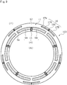
- the specific dynamic pressure generating mechanism 16 includes a liquid guide groove portion 161 communicating with the high-pressure side, a Rayleigh step 17A that extends concentrically with the stationary seal ring 102 from an inner diameter side end portion of the liquid guide groove portion 161 toward the downstream side in the circumferential direction, and a reverse Rayleigh step 17B that extends concentrically with the stationary seal ring 102 from the inner diameter side end portion of the liquid guide groove portion 161 toward the upstream side in the circumferential direction.
- the liquid guide groove portion 161 and the liquid guide groove portion 15 are formed at positions corresponding to each other in the circumferential direction.
- the liquid guide groove portion 161 functions as a deep groove portion of the specific dynamic pressure generating mechanism 16, and the Rayleigh step 17A and the reverse Rayleigh step 17B function as shallow groove portions of the specific dynamic pressure generating mechanism 16.
- the Rayleigh step 9A and the reverse Rayleigh step 9B of the dynamic pressure generating mechanism 141 are formed to be longer in the circumferential direction than the Rayleigh step 17A and the reverse Rayleigh step 17B of the specific dynamic pressure generating mechanism 16.
- the Rayleigh step 17A and the reverse Rayleigh step 17B are formed with the same depth dimension of 5 ⁇ m as that of the Rayleigh step 9A and the reverse Rayleigh step 9B.
- the width in the radial direction of the Rayleigh step 17A and the reverse Rayleigh step 17B is smaller than the width in the radial direction of the Rayleigh step 9A and the reverse Rayleigh step 9B.
- the volume of the dynamic pressure generating mechanism 141 is larger than the volume of the specific dynamic pressure generating mechanism 16.
- the dynamic pressure generated in the specific dynamic pressure generating mechanism 16 separates the sliding surfaces 11 and 21 from each other to form an appropriate liquid film therebetween, the sealed liquid F which tends to leak from the sliding surface 11 to the low-pressure side can be recovered by the dynamic pressure generating mechanism 141.
- the suctioning force of the Rayleigh step 9A and the reverse Rayleigh step 9B of the dynamic pressure generating mechanism 141 is increased, so that a balance in dynamic pressure between the dynamic pressure generating mechanism 141 on the low-pressure side and the specific dynamic pressure generating mechanism 16 on the high-pressure side can be adjusted.
- the wall portion 9a which is an end of the dynamic pressure generating mechanism 141 and a wall portion 17a which is an end of the specific dynamic pressure generating mechanism 16 are shifted from each other in the circumferential direction, the pressure can be distributed with good balance in the circumferential direction of the sliding surfaces 11 and 21.
- the length in the circumferential direction of the Rayleigh step 9A and the reverse Rayleigh step 9B may be the same as that of the Rayleigh step 17A and the reverse Rayleigh step 17B, or may be shorter than that of the Rayleigh step 17A and the reverse Rayleigh step 17B.
- the Rayleigh step 17A and the reverse Rayleigh step 17B may be formed with a depth dimension different from that of the Rayleigh step 9A and the reverse Rayleigh step 9B.
- the width in the radial direction of the Rayleigh step 17A and the reverse Rayleigh step 17B may be larger than the width in the radial direction of the Rayleigh step 9A and the reverse Rayleigh step 9B.
- the volume of the dynamic pressure generating mechanism 141 may be larger than the volume of the specific dynamic pressure generating mechanism 16.
- a specific dynamic pressure generating mechanism of a first modification example is a dimple 30 having a circular recess shape when seen in the direction orthogonal to the sliding surface 11.
- the shape, number, disposition, and the like of the dimples 30 can be freely changed.
- a specific dynamic pressure generating mechanism of a second modification example includes arc grooves 31 and 32 that extend in an arc shape while being inclined in the radial direction. Specifically, outer diameter side end portions of the arc grooves 31 and 32 communicate with the high-pressure side. A plurality of the arc grooves 31 are provided on the outer diameter side of the Rayleigh step 9A, and a plurality of the arc grooves 32 are provided on the outer diameter side of the reverse Rayleigh step 9B.
- the arc groove 31 has a shape such that when the rotating seal ring 20 rotates counterclockwise on the drawing sheet of FIG. 8B , the sealed liquid F moves toward the inner diameter side
- the arc groove 32 has a shape such that when the rotating seal ring 20 rotates clockwise on the drawing sheet of FIG. 8B , the sealed liquid F moves toward the inner diameter side.
- a stationary seal ring 103 is provided to be shifted from the dynamic pressure generating mechanism 141 in the circumferential direction such that the specific dynamic pressure generating mechanism 16 is located between the dynamic pressure generating mechanisms 141 adjacent to each other.
- the specific dynamic pressure generating mechanism 16 overlaps, in the radial direction, the dynamic pressure generating mechanisms 141 adjacent thereto.
- the sealed liquid F circulates such that the sealed liquid F which has flowed out from an end portion on the downstream side of the Rayleigh step 17A of the specific dynamic pressure generating mechanism 16 is suctioned into the reverse Rayleigh step 9B of the dynamic pressure generating mechanism 141, and the sealed liquid F which has flowed out from the downstream side of the Rayleigh step 9A of the dynamic pressure generating mechanism 141 is suctioned into the reverse Rayleigh step 17B of the specific dynamic pressure generating mechanism 16. Therefore, a liquid film can be stably formed between the sliding surfaces 11 and 21.
- the wall portion 9a which is an end of the dynamic pressure generating mechanism 141 and a wall portion 17a which is an end of the specific dynamic pressure generating mechanism 16 are shifted from each other in the circumferential direction, the pressure can be distributed with good balance in the circumferential direction of the sliding surfaces 11 and 21. Further, the sealed liquid F which has flowed out from the end portion on the downstream side of the Rayleigh step 17A of the specific dynamic pressure generating mechanism 16 can be efficiently recovered by the liquid guide groove portion 15 of the dynamic pressure generating mechanism 141.
- a Rayleigh step 171A and a reverse Rayleigh step 171B are formed from an outer diameter side end portion of the liquid guide groove portion 161, and the Rayleigh step 171A and the reverse Rayleigh step 171B communicate with the high-pressure side.
- a mechanical seal illustrated in FIG. 11 is an outside mechanical seal that seals the sealed liquid F which tends to leak from an inner diameter side of sliding surfaces toward an outer diameter side.
- the dynamic pressure generating mechanism 141 is disposed on the outer diameter side to communicate with a low-pressure side
- the specific dynamic pressure generating mechanism 16 is disposed on the inner diameter side to communicate with a high-pressure side.
- the dynamic pressure generating mechanism may be formed in an inverted L shape or an L shape corresponding to one rotational direction as in the first embodiment, and modification examples to be described later of the dynamic pressure generating mechanism may be applied.
- the specific dynamic pressure generating mechanism may not be provided as in the first embodiment, or the specific dynamic pressure generating mechanism may be formed as illustrated in FIGS. 8 to 10 .
- a Rayleigh step 91A and a reverse Rayleigh step 91B extend from a central portion in the radial direction of the liquid guide groove portion 15 in the circumferential direction. Accordingly, the liquid guide groove portion 15 further extends to the outer diameter side than the Rayleigh step 91A and the reverse Rayleigh step 91B. Therefore, the sealed liquid F on the outer diameter side can easily enter the liquid guide groove portion 15, and a large amount of the sealed liquid F can be stored in the liquid guide groove portion 15.
- a groove 92 as a shallow groove portion which is shifted to the outer diameter side of the liquid guide groove portion 15 as a deep groove portion to extend in the circumferential direction is formed in an arc shape, and the dynamic pressure generating mechanism 143 has a T shape when seen in the direction orthogonal to the sliding surface 11. Accordingly, the sealed liquid F can be directly supplied from a reverse Rayleigh step which is a portion of the groove 92 upstream of the liquid guide groove portion 15 to a Rayleigh step which is a portion downstream of the liquid guide groove portion 15. Incidentally, the position of the shallow groove portion in the deep groove portion can be freely changed as long as the shallow groove portion and the deep groove portion communicate with each other.
- the width in the circumferential direction of an outer diameter side end portion 151a communicating with the Rayleigh step 9A and the reverse Rayleigh step 9B is smaller than that of an inner diameter side end portion 151b thereof. Accordingly, the inner diameter side end portion 151b is formed to be wider in the circumferential direction than the outer diameter side end portion 151a. Therefore, the sealed liquid F adhering to a surface closer to the inside than the sliding surface 11 is easily suctioned into the liquid guide groove portion 151.
- the depth dimension of an inner diameter side end portion 152b is larger than the depth dimension of an outer diameter side end portion 152a. Accordingly, a step is formed in a communication part between the inner diameter side end portion 152b and the outer diameter side end portion 152a. Therefore, the sealed liquid F held in the inner diameter side end portion 152b is unlikely to flow out to the low-pressure side.
- a liquid guide groove portion 153 of a dynamic pressure generating mechanism 146 of a seventh modification example includes a first portion 153b that is located closer to the inner diameter side than the Rayleigh step 9A and the reverse Rayleigh step 9B, and a second portion 153a that is formed to be narrower in the circumferential direction than the first portion 153b, and extends to the outer diameter side of the first portion 153b.
- the Rayleigh step 9A and the reverse Rayleigh step 9B communicate with an outer diameter side end portion of the second portion 153a, and are provided to be separated to the outer diameter side from the first portion 153b.
- a second portion 154a communicating with the Rayleigh step 9A and the reverse Rayleigh step 9B is formed with a larger width in the circumferential direction than that of a first portion 154b located on the inner diameter side thereof.
- the first portion 154b, and the Rayleigh step 9A and the reverse Rayleigh step 9B have the same width in the radial direction, and communicate with each other over the entire width. Accordingly, the first portion 154b is narrower in width than the second portion 154a. Therefore, the sealed liquid F held in the second portion 154a on the outer diameter side is unlikely to flow out to the low-pressure side.
- a portion communicating with the Rayleigh step 9A and the reverse Rayleigh step 9B is tapered toward the outer diameter side. Accordingly, the sealed liquid F can be guided to the outer diameter side of the liquid guide groove portion 155.
- a portion located closer to the inner diameter side than the Rayleigh step 9A and the reverse Rayleigh step 9B is tapered toward the inner diameter side. Accordingly, the sealed liquid F held in the liquid guide groove portion 156 is unlikely to flow out to the low-pressure side.
- a portion located closer to the inner diameter side than the Rayleigh step 9A and the reverse Rayleigh step 9B has an arc shape, and is formed to further bulge in the circumferential direction than a portion communicating with the Rayleigh step 9A and the reverse Rayleigh step 9B. Since a portion on the inner diameter side of the liquid guide groove portion 157 is a curved surface, the sealed liquid F can flow smoothly.
- the dynamic pressure generating mechanisms 14 and dynamic pressure generating mechanisms 242 are alternately provided in the circumferential direction.
- the dynamic pressure generating mechanism 242 includes a liquid guide groove portion 158, and the reverse Rayleigh step 9B that extends from an outer diameter side end portion of the liquid guide groove portion 158 to the downstream side in the circumferential direction.
- the dynamic pressure generating mechanism 242 has an L shape when seen in the direction orthogonal to the sliding surface 11. Accordingly, the above configuration can be used without being limited by the rotational direction of the rotating seal ring 20.
- the mechanical seal for a general industrial machine has been described, but the present invention may be applied to other mechanical seals for an automobile, a water pump, and the like.
- the present invention is not limited to the mechanical seal, and may be applied to a sliding component such as a slide bearing other than the mechanical seal.
- the dynamic pressure generating mechanism may be provided only in the stationary seal ring 20, or may be provided in both the stationary seal ring and the rotating seal ring.
- a mode in which the sliding component is provided with the plurality of dynamic pressure generating mechanisms having the same shape has been provided as an example; however, a plurality of dynamic pressure generating mechanisms having different shapes may be provided.
- the interval between the dynamic pressure generating mechanism, the number of the dynamic pressure generating mechanisms, or the like can be appropriately changed.
Landscapes
- Engineering & Computer Science (AREA)
- General Engineering & Computer Science (AREA)
- Mechanical Engineering (AREA)
- Chemical & Material Sciences (AREA)
- Oil, Petroleum & Natural Gas (AREA)
- Physics & Mathematics (AREA)
- Fluid Mechanics (AREA)
- Mechanical Sealing (AREA)
- Sliding-Contact Bearings (AREA)
Applications Claiming Priority (2)
| Application Number | Priority Date | Filing Date | Title |
|---|---|---|---|
| JP2019017872 | 2019-02-04 | ||
| PCT/JP2020/003643 WO2020162348A1 (fr) | 2019-02-04 | 2020-01-31 | Composant coulissant |
Publications (4)
| Publication Number | Publication Date |
|---|---|
| EP3922876A1 true EP3922876A1 (fr) | 2021-12-15 |
| EP3922876A4 EP3922876A4 (fr) | 2022-11-02 |
| EP3922876C0 EP3922876C0 (fr) | 2024-12-04 |
| EP3922876B1 EP3922876B1 (fr) | 2024-12-04 |
Family
ID=71947970
Family Applications (1)
| Application Number | Title | Priority Date | Filing Date |
|---|---|---|---|
| EP20753172.4A Active EP3922876B1 (fr) | 2019-02-04 | 2020-01-31 | Composant coulissant |
Country Status (6)
| Country | Link |
|---|---|
| US (1) | US12259043B2 (fr) |
| EP (1) | EP3922876B1 (fr) |
| JP (2) | JP7313788B2 (fr) |
| KR (2) | KR102655679B1 (fr) |
| CN (2) | CN115853894A (fr) |
| WO (1) | WO2020162348A1 (fr) |
Cited By (2)
| Publication number | Priority date | Publication date | Assignee | Title |
|---|---|---|---|---|
| EP4119807A4 (fr) * | 2020-03-09 | 2024-04-24 | Eagle Industry Co., Ltd. | Composant de coulissement |
| US12140179B2 (en) | 2020-03-26 | 2024-11-12 | Eagle Industry Co., Ltd. | Sliding component |
Families Citing this family (8)
| Publication number | Priority date | Publication date | Assignee | Title |
|---|---|---|---|---|
| JP7520473B2 (ja) * | 2021-04-28 | 2024-07-23 | イーグル工業株式会社 | 摺動部品 |
| WO2023027002A1 (fr) * | 2021-08-25 | 2023-03-02 | イーグル工業株式会社 | Composant coulissant |
| KR20240042051A (ko) | 2021-08-25 | 2024-04-01 | 이구루코교 가부시기가이샤 | 슬라이딩 부품 |
| EP4411182A4 (fr) * | 2021-09-28 | 2025-09-17 | Eagle Ind Co Ltd | Composant coulissant |
| JP7767584B2 (ja) * | 2022-03-24 | 2025-11-11 | イーグル工業株式会社 | 摺動部品 |
| KR20250008107A (ko) | 2022-05-19 | 2025-01-14 | 이구루코교 가부시기가이샤 | 슬라이딩 부품 |
| CN119301388A (zh) | 2022-06-07 | 2025-01-10 | 伊格尔工业股份有限公司 | 滑动部件 |
| KR20260049805A (ko) * | 2023-09-05 | 2026-04-14 | 이구루코교 가부시기가이샤 | 슬라이딩 부품 |
Family Cites Families (179)
| Publication number | Priority date | Publication date | Assignee | Title |
|---|---|---|---|---|
| US3383116A (en) | 1964-09-30 | 1968-05-14 | J C Carter Company | Face seal |
| FR1505487A (fr) | 1966-10-28 | 1967-12-15 | Guinard Pompes | Perfectionnement aux joints tournants à régulation de fuite |
| US3695789A (en) | 1970-04-13 | 1972-10-03 | Case Co J I | Balancing mechanism for fluid translating device |
| US3704019A (en) | 1970-06-19 | 1972-11-28 | Gen Electric | Spiral groove face seals |
| US3675935A (en) | 1970-07-13 | 1972-07-11 | Nasa | Spiral groove seal |
| US3782737A (en) | 1970-07-13 | 1974-01-01 | Nasa | Spiral groove seal |
| NL7213192A (fr) | 1972-09-29 | 1974-04-02 | ||
| US4056478A (en) | 1973-10-04 | 1977-11-01 | Sargent Industries, Inc. | Bearing material employing frangible microcapsules containing lubricant |
| JPS5134974A (en) | 1974-09-19 | 1976-03-25 | Kinugawa Rubber Ind | Dainamitsukushiiru no seiho |
| DE2504204C3 (de) | 1975-02-01 | 1981-11-12 | Skf Kugellagerfabriken Gmbh, 8720 Schweinfurt | Selbstdruckerzeugendes Axialgleitlager |
| FR2342440A1 (fr) | 1976-02-27 | 1977-09-23 | Ca Atomic Energy Ltd | Joint facial pour arbre tournant |
| DE2610045C2 (de) | 1976-03-11 | 1982-06-16 | M.A.N. Maschinenfabrik Augsburg-Nürnberg AG, 4200 Oberhausen | Gasgesperrte Wellendichtung |
| DE2622772C3 (de) | 1976-05-21 | 1980-05-08 | Hoesch Werke Ag, 4600 Dortmund | Einrichtung für den Transport und Wechsel von Walzen an Walzenbearbeitungsmaschinen |
| DE2624849C3 (de) | 1976-06-03 | 1981-12-03 | Skf Kugellagerfabriken Gmbh, 8720 Schweinfurt | Selbstdruckerzeugendes Radialgleitlager |
| JPS5693599U (fr) | 1979-12-21 | 1981-07-25 | ||
| JPS57163770A (en) | 1981-04-01 | 1982-10-08 | Eagle Ind Co Ltd | Mechanical seal |
| DE3223703C2 (de) | 1982-06-25 | 1984-05-30 | M.A.N. Maschinenfabrik Augsburg-Nürnberg AG, 4200 Oberhausen | Gasgesperrte Wellendichtung mit radialem Dichtspalt |
| JPS5960145U (ja) | 1982-10-15 | 1984-04-19 | 株式会社太洋商会 | ロ−ル状連続袋 |
| JPS59195253A (ja) | 1983-04-20 | 1984-11-06 | Canon Inc | 電子写真装置 |
| JPS59195254A (ja) | 1983-04-20 | 1984-11-06 | Fujitsu Ltd | プリンタの露光量調整方法及び装置 |
| CH677266A5 (fr) | 1986-10-28 | 1991-04-30 | Pacific Wietz Gmbh & Co Kg | |
| US5368314A (en) | 1986-10-28 | 1994-11-29 | Pacific Wietz Gmbh & Co. Kg | Contactless pressurizing-gas shaft seal |
| US4889348A (en) | 1987-06-10 | 1989-12-26 | John Crane-Houdaille, Inc. | Spiral groove seal system for high vapor-pressure liquids |
| JPH02136863A (ja) | 1988-11-18 | 1990-05-25 | Toshiba Corp | 画像形成装置の現像剤 |
| DE3839106A1 (de) | 1988-11-18 | 1990-05-23 | Burgmann Dichtungswerk Feodor | Gleitringdichtung |
| JPH06105105B2 (ja) | 1989-03-03 | 1994-12-21 | 日本ピラー工業株式会社 | 端面非接触形メカニカルシール |
| JPH0646071B2 (ja) * | 1989-04-14 | 1994-06-15 | 日本ピラー工業株式会社 | 非接触形メカニカルシール |
| US5066026A (en) | 1990-06-11 | 1991-11-19 | Kaydon Corporation | Gas face seal |
| JPH0660690B2 (ja) * | 1990-06-18 | 1994-08-10 | 日本ピラー工業株式会社 | 動圧非接触形メカニカルシール |
| JPH0756345B2 (ja) | 1990-07-09 | 1995-06-14 | 株式会社荏原製作所 | 非接触端面シール |
| US5071141A (en) | 1990-07-17 | 1991-12-10 | John Crane Inc. | Spiral groove seal arrangement for high vapor-pressure liquids |
| US5224714A (en) | 1990-07-18 | 1993-07-06 | Ebara Corporation | Noncontacting face seal |
| GB9103217D0 (en) | 1991-02-15 | 1991-04-03 | Crane John Uk Ltd | Mechanical face seals |
| JPH07117167B2 (ja) | 1991-05-09 | 1995-12-18 | 日本ピラー工業株式会社 | 非接触形メカニカルシール装置 |
| JP2516301B2 (ja) | 1991-06-13 | 1996-07-24 | インターナショナル・ビジネス・マシーンズ・コーポレイション | テ―プ駆動装置 |
| US5174584A (en) | 1991-07-15 | 1992-12-29 | General Electric Company | Fluid bearing face seal for gas turbine engines |
| JPH0560247A (ja) | 1991-08-26 | 1993-03-09 | Nippon Pillar Packing Co Ltd | 非接触形メカニカルシール |
| JPH0680623B2 (ja) | 1991-09-25 | 1994-10-12 | 北海道電力株式会社 | 電力需給用計器用変成器 |
| US5447316A (en) | 1992-02-06 | 1995-09-05 | Eagle Industry Co., Ltd. | Gas seal |
| JPH05296248A (ja) | 1992-04-21 | 1993-11-09 | Sumitomo Electric Ind Ltd | 摺動部材 |
| JP3517888B2 (ja) | 1992-09-18 | 2004-04-12 | ブラザー工業株式会社 | カラー電子写真画像形成装置 |
| JPH0769020B2 (ja) | 1992-10-07 | 1995-07-26 | 日本ピラー工業株式会社 | メカニカルシール |
| JPH0769021B2 (ja) | 1992-12-11 | 1995-07-26 | 日本ピラー工業株式会社 | 非接触形軸封装置 |
| US5441283A (en) | 1993-08-03 | 1995-08-15 | John Crane Inc. | Non-contacting mechanical face seal |
| CA2170746C (fr) | 1993-09-01 | 2005-01-25 | Josef Sedy | Joint a portee plane, avec rainures a angle et annulaires |
| JP2563081B2 (ja) * | 1994-03-22 | 1996-12-11 | 日本ピラー工業株式会社 | 非接触形軸封装置 |
| US5558341A (en) | 1995-01-11 | 1996-09-24 | Stein Seal Company | Seal for sealing an incompressible fluid between a relatively stationary seal and a movable member |
| US5769604A (en) | 1995-05-04 | 1998-06-23 | Eg&G Sealol, Inc. | Face seal device having high angular compliance |
| JP2903458B2 (ja) | 1995-09-29 | 1999-06-07 | 日本ピラー工業株式会社 | 大型缶水循環ポンプ用熱水軸封装置 |
| JPH09292034A (ja) | 1996-04-25 | 1997-11-11 | Mitsubishi Heavy Ind Ltd | メカニカルシール |
| US5833518A (en) | 1996-08-02 | 1998-11-10 | Flowserve Management Company | Method for forming a wavy face ring |
| US5834094A (en) | 1996-09-30 | 1998-11-10 | Surface Technologies Ltd. | Bearing having micropores and design method thereof |
| JPH10281299A (ja) | 1997-04-11 | 1998-10-23 | Mitsubishi Heavy Ind Ltd | メカニカルシール装置 |
| JPH10292867A (ja) | 1997-04-16 | 1998-11-04 | Mitsubishi Heavy Ind Ltd | ガスシール装置 |
| US6152452A (en) | 1997-10-17 | 2000-11-28 | Wang; Yuming | Face seal with spiral grooves |
| CN1133834C (zh) | 1997-11-21 | 2004-01-07 | 日本皮拉工业株式会社 | 静压型非接触气封 |
| WO1999027281A1 (fr) | 1997-11-21 | 1999-06-03 | Nippon Pillar Packing Co., Ltd. | Joint a gaz sans contact a pression statique |
| JPH11287329A (ja) | 1998-04-03 | 1999-10-19 | Eagle Ind Co Ltd | 摺動材 |
| US6213473B1 (en) | 1999-03-06 | 2001-04-10 | Utex Industries, Inc. | Double gas seal with coplanar pad faces |
| JP4232278B2 (ja) * | 1999-06-25 | 2009-03-04 | パナソニック株式会社 | 動圧軸受及びそれを搭載したスピンドルモータ |
| JP3066367U (ja) | 1999-08-05 | 2000-02-18 | 第一精工株式会社 | 遊漁用容器と付属部材 |
| US7044470B2 (en) | 2000-07-12 | 2006-05-16 | Perkinelmer, Inc. | Rotary face seal assembly |
| US6446976B1 (en) | 2000-09-06 | 2002-09-10 | Flowserve Management Company | Hydrodynamic face seal with grooved sealing dam for zero-leakage |
| CN2460801Y (zh) | 2001-01-18 | 2001-11-21 | 王玉明 | 可双向旋转的螺旋槽端面密封装置 |
| US6454268B1 (en) | 2001-02-09 | 2002-09-24 | Eagle Industry Co., Ltd. | Shaft seal device |
| US6655693B2 (en) | 2001-04-26 | 2003-12-02 | John Crane Inc. | Non-contacting gas compressor seal |
| US6692006B2 (en) | 2001-10-15 | 2004-02-17 | Stein Seal Company | High-pressure film-riding seals for rotating shafts |
| JP4054608B2 (ja) | 2002-05-23 | 2008-02-27 | イーグル工業株式会社 | 板ブラシシール |
| CN100427816C (zh) | 2002-09-20 | 2008-10-22 | 徐万福 | 一种由角形微槽族组成的螺旋槽端面机械密封 |
| JP4316956B2 (ja) | 2002-10-23 | 2009-08-19 | イーグル工業株式会社 | 摺動部品 |
| JP4719414B2 (ja) | 2003-12-22 | 2011-07-06 | イーグル工業株式会社 | 摺動部品 |
| JP4119398B2 (ja) | 2004-04-30 | 2008-07-16 | 日本ピラー工業株式会社 | 非接触形メカニカルシール |
| GB2413603A (en) | 2004-04-30 | 2005-11-02 | Corac Group Plc | A dry gas seal assembly |
| US7377518B2 (en) | 2004-05-28 | 2008-05-27 | John Crane Inc. | Mechanical seal ring assembly with hydrodynamic pumping mechanism |
| JP4262656B2 (ja) | 2004-09-10 | 2009-05-13 | 日本ピラー工業株式会社 | 非接触型シール装置 |
| JP2006090524A (ja) | 2004-09-27 | 2006-04-06 | Nissei Co Ltd | 動圧流体軸受 |
| US7744094B2 (en) | 2004-11-09 | 2010-06-29 | Eagle Industry Co., Ltd. | Mechanical seal device |
| JP2006183702A (ja) | 2004-12-27 | 2006-07-13 | Hitachi Industrial Equipment Systems Co Ltd | スラスト軸受 |
| JP2007162045A (ja) | 2005-12-12 | 2007-06-28 | Japan Science & Technology Agency | 摺動材及びその製造方法 |
| US20070228664A1 (en) | 2006-03-31 | 2007-10-04 | Krishnamurthy Anand | Mechanical seals and methods of making |
| US7793940B2 (en) | 2006-05-16 | 2010-09-14 | Skf Usa Inc. | Mechanical end face seal with ultrahard face material |
| EP2047149B1 (fr) | 2006-05-26 | 2015-08-12 | Sulzer Metco (US) Inc. | Joints mécaniques et procédé de fabrication |
| US20080284105A1 (en) | 2006-06-21 | 2008-11-20 | Thurai Manik Vasagar | Low and reverse pressure application hydrodynamic pressurizing seals |
| JP5580532B2 (ja) | 2006-07-25 | 2014-08-27 | イーグル工業株式会社 | メカニカルシール装置 |
| US8162322B2 (en) | 2006-10-25 | 2012-04-24 | Rexnord Industries, Llc | Hydrodynamic seal with circumferentially varying lift force |
| PL212538B1 (pl) | 2006-11-12 | 2012-10-31 | Anga Uszczelnienia Mechaniczne Spolka Z Ograniczona Odpowiedzialnoscia | Pierscien slizgowy |
| WO2009066664A1 (fr) | 2007-11-20 | 2009-05-28 | Eagle Industry Co., Ltd. | Joint d'étanchéité mécanique et joint d'étanchéité en tandem |
| US20090326087A1 (en) | 2008-06-27 | 2009-12-31 | Xerox Corporation | Method for treating microcapsules for use in imaging member |
| DE102008038396A1 (de) | 2008-08-19 | 2010-02-25 | Surcoatec International Ag | Gleitring für eine Gleitringdichtung |
| US8100405B2 (en) | 2009-01-06 | 2012-01-24 | General Electric Company | System and method for providing compliant rotating seals |
| US9551421B2 (en) | 2009-02-10 | 2017-01-24 | Nok Corporation | Sliding member and process for producing the same |
| JP5456772B2 (ja) | 2009-05-25 | 2014-04-02 | イーグル工業株式会社 | シール装置 |
| CN201496542U (zh) | 2009-08-06 | 2010-06-02 | 浙江工业大学 | 三维似鱼鳞织构底面型槽流体动压型液体机械密封结构 |
| CN101793324B (zh) | 2009-08-06 | 2011-12-28 | 浙江工业大学 | 三维似鱼鳞织构底面型槽流体动压型液体机械密封结构 |
| CN101644333B (zh) | 2009-08-20 | 2011-08-31 | 浙江工业大学 | 三维似羽毛织构底面型槽气体端面密封结构 |
| WO2011025484A1 (fr) | 2009-08-27 | 2011-03-03 | Stein Seal Company | Système de joint circonférentiel hydrodynamique pour grandes translations |
| JP2011074931A (ja) | 2009-09-29 | 2011-04-14 | Ihi Corp | 可燃性ガス圧縮機のシール装置 |
| WO2011105513A1 (fr) * | 2010-02-26 | 2011-09-01 | Nok株式会社 | Bague d'étanchéité |
| JP5518527B2 (ja) | 2010-03-04 | 2014-06-11 | イーグル工業株式会社 | 摺動部品 |
| WO2011115073A1 (fr) | 2010-03-15 | 2011-09-22 | イーグル工業株式会社 | Elément coulissant |
| JP5122607B2 (ja) * | 2010-06-17 | 2013-01-16 | キヤノンマシナリー株式会社 | 平面摺動機構 |
| DE202010011173U1 (de) | 2010-08-09 | 2011-12-22 | Eagleburgmann Germany Gmbh & Co. Kg | Gleitring mit verbesserten Einlaufeigenschaften |
| JP2012062534A (ja) | 2010-09-16 | 2012-03-29 | Jtekt Corp | 摺動部材 |
| JP5693599B2 (ja) | 2010-10-06 | 2015-04-01 | イーグル工業株式会社 | 摺動部品 |
| JP2012122135A (ja) | 2010-11-18 | 2012-06-28 | Furukawa Electric Co Ltd:The | めっき助材、めっき液およびめっき材料 |
| JP5968889B2 (ja) | 2011-09-03 | 2016-08-10 | イーグル工業株式会社 | 摺動部品 |
| US9494239B2 (en) | 2011-09-03 | 2016-11-15 | Eagle Industry Co., Ltd. | Sliding parts |
| JP5960145B2 (ja) | 2011-09-10 | 2016-08-02 | イーグル工業株式会社 | 摺動部品及びその製造方法 |
| US9371912B2 (en) | 2011-09-10 | 2016-06-21 | Eagle Industry Co., Ltd. | Sliding parts |
| CN102359596A (zh) * | 2011-09-26 | 2012-02-22 | 清华大学 | 一种单向旋转三维l形槽端面密封结构 |
| DE102011116162A1 (de) | 2011-10-14 | 2013-04-18 | Eagleburgmann Germany Gmbh & Co. Kg | Gleitring einer Gleitringdichtungsanordnung mit laufzeitverlängernden Eigenschaften sowie Verfahren zu dessen Herstellung |
| JP5928106B2 (ja) * | 2012-04-02 | 2016-06-01 | オイレス工業株式会社 | 静圧気体軸受及びこの静圧気体軸受を用いた直動案内装置 |
| US9512923B2 (en) | 2012-05-21 | 2016-12-06 | Eagle Industry Co., Ltd. | Sliding component |
| CN104334939B (zh) * | 2012-08-04 | 2017-05-31 | 伊格尔工业股份有限公司 | 滑动部件 |
| WO2014024741A1 (fr) | 2012-08-04 | 2014-02-13 | イーグル工業株式会社 | Composant de coulissement |
| US20150115540A1 (en) | 2012-09-11 | 2015-04-30 | Eagle Industry Co. Ltd | Sliding component |
| US10612666B2 (en) * | 2012-09-11 | 2020-04-07 | Eagle Industry Co., Ltd. | Sliding component |
| CN104334938B (zh) | 2012-09-29 | 2017-07-07 | 伊格尔工业股份有限公司 | 滑动部件 |
| CN104379975B (zh) | 2012-10-18 | 2017-05-31 | 伊格尔工业股份有限公司 | 滑动部件 |
| EP2948699B1 (fr) | 2013-01-23 | 2018-08-15 | Flowserve Management Company | Joint d'étanchéité de face mécanique ayant un motif de face trapézoïdal inversé |
| CN203098871U (zh) | 2013-01-30 | 2013-07-31 | 浙江工业大学 | 似蘑菇型槽双向旋转流体动压型机械密封结构 |
| WO2014142265A1 (fr) | 2013-03-14 | 2014-09-18 | イーグルブルグマンジャパン株式会社 | Dispositif de joint mécanique |
| WO2014148316A1 (fr) | 2013-03-17 | 2014-09-25 | イーグル工業株式会社 | Élément coulissant |
| EP2977655B1 (fr) | 2013-03-17 | 2018-07-18 | Eagle Industry Co., Ltd. | Élément glissant |
| US9587745B2 (en) | 2013-04-24 | 2017-03-07 | Eagle Industry Co., Ltd. | Sliding component |
| GB2513867A (en) | 2013-05-07 | 2014-11-12 | Mahle Int Gmbh | Sliding engine component |
| CN103267132B (zh) | 2013-05-28 | 2015-08-05 | 南京林业大学 | 自泵送流体动压型机械密封 |
| CN203641506U (zh) | 2013-08-20 | 2014-06-11 | 浙江工业大学 | 倾斜渐变多孔端面非接触式机械密封结构 |
| JP6210814B2 (ja) | 2013-09-26 | 2017-10-11 | ポリプラスチックス株式会社 | 摺動部材 |
| JP2015068330A (ja) | 2013-10-01 | 2015-04-13 | 三菱重工業株式会社 | 摺動部材 |
| CN103557229A (zh) | 2013-10-22 | 2014-02-05 | 申科滑动轴承股份有限公司 | 一种水润滑阶梯瓦动压推力轴承的设计方法 |
| CN103557334A (zh) | 2013-11-14 | 2014-02-05 | 江苏大学 | 一种实现零泄漏非接触的多端面组合式机械密封 |
| EP3098486B1 (fr) | 2014-01-24 | 2020-03-11 | NOK Corporation | Bague d'étanchéité |
| EP3112078B1 (fr) | 2014-02-24 | 2020-04-15 | Eagle Industry Co., Ltd. | Élément glissant et procédé de traitement d'élément glissant |
| US20150345642A1 (en) | 2014-05-29 | 2015-12-03 | Caterpillar Inc. | Thin film coating on mechanical face seals |
| US9353865B2 (en) | 2014-06-03 | 2016-05-31 | Thermo King Corporation | Mechanical face seal |
| JP6479023B2 (ja) | 2014-09-04 | 2019-03-06 | イーグル工業株式会社 | メカニカルシール |
| US10274086B2 (en) | 2014-09-20 | 2019-04-30 | Eagle Industry Co., Ltd. | Sliding component |
| JP6224568B2 (ja) | 2014-10-17 | 2017-11-01 | イーグル工業株式会社 | メカニカルシール |
| CN107110370B (zh) * | 2014-11-08 | 2019-09-13 | 伊格尔工业股份有限公司 | 滑动部件 |
| WO2016104535A1 (fr) | 2014-12-22 | 2016-06-30 | イーグル工業株式会社 | Palier de coulissement et pompe |
| KR101970231B1 (ko) | 2015-02-14 | 2019-04-18 | 이구루코교 가부시기가이샤 | 슬라이딩 부품 |
| US10190689B2 (en) | 2015-03-16 | 2019-01-29 | Nok Corporation | Seal ring |
| JP6444492B2 (ja) * | 2015-04-15 | 2018-12-26 | イーグル工業株式会社 | 摺動部品 |
| CN107532723B (zh) | 2015-04-16 | 2019-11-22 | 伊格尔工业股份有限公司 | 滑动部件 |
| JP6678169B2 (ja) * | 2015-05-19 | 2020-04-08 | イーグル工業株式会社 | 摺動部品 |
| BR112017023658A2 (pt) * | 2015-05-20 | 2018-07-17 | Eagle Industry Co., Ltd. | componente deslizante |
| JP6678170B2 (ja) | 2015-05-21 | 2020-04-08 | イーグル工業株式会社 | 摺動部品 |
| CN107735604B (zh) * | 2015-06-15 | 2023-04-11 | 伊格尔工业股份有限公司 | 滑动部件 |
| AU2016286896A1 (en) | 2015-06-30 | 2018-01-18 | Eagle Industry Co., Ltd. | Seal device |
| CN105014489B (zh) | 2015-07-03 | 2020-07-17 | 霍凤伟 | 一种密封环加工方法及采用该方法加工的密封环 |
| CN108138967B (zh) | 2015-10-05 | 2020-04-07 | 伊格尔工业股份有限公司 | 滑动部件 |
| JP6383720B2 (ja) | 2015-12-16 | 2018-08-29 | 株式会社不二工機 | 可変容量型圧縮機用制御弁 |
| JP6568578B2 (ja) | 2015-12-25 | 2019-08-28 | 三菱マテリアル株式会社 | 焼結含油軸受及びその製造方法 |
| KR20170093349A (ko) | 2016-02-05 | 2017-08-16 | 주식회사 뉴로스 | 가변용량 압축기의 전자제어밸브 |
| US11162591B2 (en) | 2016-03-10 | 2021-11-02 | General Electric Company | Seal ring assembly for a dynamoelectric machine |
| US11473626B2 (en) | 2016-05-16 | 2022-10-18 | Roller Bearing Company Of America, Inc. | Bearing system with self-lubrication features, seals, grooves and slots for maintenance-free operation |
| CN205877184U (zh) | 2016-06-20 | 2017-01-11 | 昆明理工大学 | 一种具有仿枫叶形槽的机械密封环 |
| CN205877198U (zh) | 2016-06-20 | 2017-01-11 | 昆明理工大学 | 一种具有椭圆槽的机械密封环 |
| JP6626789B2 (ja) | 2016-06-28 | 2019-12-25 | 株式会社不二工機 | 可変容量型圧縮機用制御弁 |
| CN106439023B (zh) | 2016-07-28 | 2018-03-06 | 浙江工业大学 | 一种余弦曲线型机械密封端面结构 |
| EP3508763A4 (fr) | 2016-09-01 | 2020-04-15 | Eagle Industry Co., Ltd. | Élément coulissant |
| EP3540274B1 (fr) | 2016-11-14 | 2023-01-04 | Eagle Industry Co., Ltd. | Composant coulissant |
| CN109923340B (zh) | 2016-11-16 | 2020-09-11 | 伊格尔工业股份有限公司 | 滑动组件 |
| JP6861730B2 (ja) | 2016-12-07 | 2021-04-21 | イーグル工業株式会社 | しゅう動部品 |
| CN106763778B (zh) | 2016-12-12 | 2019-07-16 | 昆明理工大学 | 一种具有多级螺旋槽的上游泵送机械密封环 |
| WO2018139231A1 (fr) | 2017-01-30 | 2018-08-02 | イーグル工業株式会社 | Composant coulissant |
| EP3575621B1 (fr) | 2017-01-30 | 2022-01-12 | Eagle Industry Co., Ltd. | Composant coulissant |
| JP7086489B2 (ja) | 2017-07-07 | 2022-06-20 | イーグル工業株式会社 | 摺動部品 |
| EP3653913A4 (fr) | 2017-07-13 | 2021-03-17 | Eagle Industry Co., Ltd. | Élément de coulissement |
| CN107489770A (zh) | 2017-09-29 | 2017-12-19 | 重庆三峡学院 | 一种双向机械密封环 |
| JP7234123B2 (ja) | 2017-10-03 | 2023-03-07 | イーグル工業株式会社 | 摺動部品 |
| CN107906206A (zh) | 2017-12-28 | 2018-04-13 | 温州市天成密封件制造有限公司 | 一种可双向旋转的筒罩型槽端面机械密封结构 |
| EP3739242A4 (fr) | 2018-01-12 | 2021-10-13 | Eagle Industry Co., Ltd. | Élément coulissant |
| WO2019151396A1 (fr) | 2018-02-01 | 2019-08-08 | イーグル工業株式会社 | Pièces coulissantes |
| WO2019221226A1 (fr) | 2018-05-17 | 2019-11-21 | イーグル工業株式会社 | Bague d'étanchéité |
| WO2019221228A1 (fr) | 2018-05-17 | 2019-11-21 | イーグル工業株式会社 | Bague d'étanchéité |
| WO2020027102A1 (fr) | 2018-08-01 | 2020-02-06 | イーグル工業株式会社 | Élément coulissant |
| CN109237042A (zh) | 2018-11-14 | 2019-01-18 | 北京动力机械研究所 | 自清洗齿形动压型槽端面机械密封结构 |
-
2020
- 2020-01-31 US US17/424,850 patent/US12259043B2/en active Active
- 2020-01-31 KR KR1020237005133A patent/KR102655679B1/ko active Active
- 2020-01-31 WO PCT/JP2020/003643 patent/WO2020162348A1/fr not_active Ceased
- 2020-01-31 CN CN202211560829.8A patent/CN115853894A/zh active Pending
- 2020-01-31 CN CN202080010580.6A patent/CN113330224A/zh active Pending
- 2020-01-31 KR KR1020217025490A patent/KR102647265B1/ko active Active
- 2020-01-31 JP JP2020571157A patent/JP7313788B2/ja active Active
- 2020-01-31 EP EP20753172.4A patent/EP3922876B1/fr active Active
-
2023
- 2023-06-28 JP JP2023105640A patent/JP7538920B2/ja active Active
Cited By (3)
| Publication number | Priority date | Publication date | Assignee | Title |
|---|---|---|---|---|
| EP4119807A4 (fr) * | 2020-03-09 | 2024-04-24 | Eagle Industry Co., Ltd. | Composant de coulissement |
| US12110968B2 (en) | 2020-03-09 | 2024-10-08 | Eagle Industry Co., Ltd. | Sliding component |
| US12140179B2 (en) | 2020-03-26 | 2024-11-12 | Eagle Industry Co., Ltd. | Sliding component |
Also Published As
| Publication number | Publication date |
|---|---|
| KR102655679B1 (ko) | 2024-04-09 |
| JP7313788B2 (ja) | 2023-07-25 |
| EP3922876C0 (fr) | 2024-12-04 |
| US20220120315A1 (en) | 2022-04-21 |
| CN113330224A (zh) | 2021-08-31 |
| US12259043B2 (en) | 2025-03-25 |
| JPWO2020162348A1 (ja) | 2021-12-09 |
| EP3922876A4 (fr) | 2022-11-02 |
| KR20210111855A (ko) | 2021-09-13 |
| EP3922876B1 (fr) | 2024-12-04 |
| JP2023120417A (ja) | 2023-08-29 |
| KR20230026544A (ko) | 2023-02-24 |
| JP7538920B2 (ja) | 2024-08-22 |
| CN115853894A (zh) | 2023-03-28 |
| KR102647265B1 (ko) | 2024-03-14 |
| WO2020162348A1 (fr) | 2020-08-13 |
Similar Documents
| Publication | Publication Date | Title |
|---|---|---|
| EP3922876B1 (fr) | Composant coulissant | |
| EP3922872B1 (fr) | Élément coulissant | |
| EP3922874A1 (fr) | Élément coulissant | |
| KR102576181B1 (ko) | 슬라이딩 부품 | |
| US12385567B2 (en) | Sliding component | |
| US12013040B2 (en) | Sliding components |
Legal Events
| Date | Code | Title | Description |
|---|---|---|---|
| STAA | Information on the status of an ep patent application or granted ep patent |
Free format text: STATUS: THE INTERNATIONAL PUBLICATION HAS BEEN MADE |
|
| PUAI | Public reference made under article 153(3) epc to a published international application that has entered the european phase |
Free format text: ORIGINAL CODE: 0009012 |
|
| STAA | Information on the status of an ep patent application or granted ep patent |
Free format text: STATUS: REQUEST FOR EXAMINATION WAS MADE |
|
| 17P | Request for examination filed |
Effective date: 20210816 |
|
| AK | Designated contracting states |
Kind code of ref document: A1 Designated state(s): AL AT BE BG CH CY CZ DE DK EE ES FI FR GB GR HR HU IE IS IT LI LT LU LV MC MK MT NL NO PL PT RO RS SE SI SK SM TR |
|
| DAV | Request for validation of the european patent (deleted) | ||
| DAX | Request for extension of the european patent (deleted) | ||
| A4 | Supplementary search report drawn up and despatched |
Effective date: 20221004 |
|
| RIC1 | Information provided on ipc code assigned before grant |
Ipc: F16C 33/10 20060101ALI20220927BHEP Ipc: F16J 15/34 20060101ALI20220927BHEP Ipc: F16C 33/74 20060101ALI20220927BHEP Ipc: F16C 17/04 20060101AFI20220927BHEP |
|
| GRAP | Despatch of communication of intention to grant a patent |
Free format text: ORIGINAL CODE: EPIDOSNIGR1 |
|
| STAA | Information on the status of an ep patent application or granted ep patent |
Free format text: STATUS: GRANT OF PATENT IS INTENDED |
|
| INTG | Intention to grant announced |
Effective date: 20240802 |
|
| GRAS | Grant fee paid |
Free format text: ORIGINAL CODE: EPIDOSNIGR3 |
|
| GRAA | (expected) grant |
Free format text: ORIGINAL CODE: 0009210 |
|
| STAA | Information on the status of an ep patent application or granted ep patent |
Free format text: STATUS: THE PATENT HAS BEEN GRANTED |
|
| AK | Designated contracting states |
Kind code of ref document: B1 Designated state(s): AL AT BE BG CH CY CZ DE DK EE ES FI FR GB GR HR HU IE IS IT LI LT LU LV MC MK MT NL NO PL PT RO RS SE SI SK SM TR |
|
| REG | Reference to a national code |
Ref country code: CH Ref legal event code: EP |
|
| REG | Reference to a national code |
Ref country code: DE Ref legal event code: R096 Ref document number: 602020042522 Country of ref document: DE |
|
| REG | Reference to a national code |
Ref country code: IE Ref legal event code: FG4D |
|
| U01 | Request for unitary effect filed |
Effective date: 20241204 |
|
| U07 | Unitary effect registered |
Designated state(s): AT BE BG DE DK EE FI FR IT LT LU LV MT NL PT RO SE SI Effective date: 20241210 |
|
| U20 | Renewal fee for the european patent with unitary effect paid |
Year of fee payment: 6 Effective date: 20250116 |
|
| PG25 | Lapsed in a contracting state [announced via postgrant information from national office to epo] |
Ref country code: HR Free format text: LAPSE BECAUSE OF FAILURE TO SUBMIT A TRANSLATION OF THE DESCRIPTION OR TO PAY THE FEE WITHIN THE PRESCRIBED TIME-LIMIT Effective date: 20241204 |
|
| PG25 | Lapsed in a contracting state [announced via postgrant information from national office to epo] |
Ref country code: ES Free format text: LAPSE BECAUSE OF FAILURE TO SUBMIT A TRANSLATION OF THE DESCRIPTION OR TO PAY THE FEE WITHIN THE PRESCRIBED TIME-LIMIT Effective date: 20241204 |
|
| PG25 | Lapsed in a contracting state [announced via postgrant information from national office to epo] |
Ref country code: NO Free format text: LAPSE BECAUSE OF FAILURE TO SUBMIT A TRANSLATION OF THE DESCRIPTION OR TO PAY THE FEE WITHIN THE PRESCRIBED TIME-LIMIT Effective date: 20250304 |
|
| PG25 | Lapsed in a contracting state [announced via postgrant information from national office to epo] |
Ref country code: GR Free format text: LAPSE BECAUSE OF FAILURE TO SUBMIT A TRANSLATION OF THE DESCRIPTION OR TO PAY THE FEE WITHIN THE PRESCRIBED TIME-LIMIT Effective date: 20250305 |
|
| PG25 | Lapsed in a contracting state [announced via postgrant information from national office to epo] |
Ref country code: RS Free format text: LAPSE BECAUSE OF FAILURE TO SUBMIT A TRANSLATION OF THE DESCRIPTION OR TO PAY THE FEE WITHIN THE PRESCRIBED TIME-LIMIT Effective date: 20250304 |
|
| PG25 | Lapsed in a contracting state [announced via postgrant information from national office to epo] |
Ref country code: SM Free format text: LAPSE BECAUSE OF FAILURE TO SUBMIT A TRANSLATION OF THE DESCRIPTION OR TO PAY THE FEE WITHIN THE PRESCRIBED TIME-LIMIT Effective date: 20241204 |
|
| PG25 | Lapsed in a contracting state [announced via postgrant information from national office to epo] |
Ref country code: PL Free format text: LAPSE BECAUSE OF FAILURE TO SUBMIT A TRANSLATION OF THE DESCRIPTION OR TO PAY THE FEE WITHIN THE PRESCRIBED TIME-LIMIT Effective date: 20241204 |
|
| PG25 | Lapsed in a contracting state [announced via postgrant information from national office to epo] |
Ref country code: IS Free format text: LAPSE BECAUSE OF FAILURE TO SUBMIT A TRANSLATION OF THE DESCRIPTION OR TO PAY THE FEE WITHIN THE PRESCRIBED TIME-LIMIT Effective date: 20250404 |
|
| PG25 | Lapsed in a contracting state [announced via postgrant information from national office to epo] |
Ref country code: SK Free format text: LAPSE BECAUSE OF FAILURE TO SUBMIT A TRANSLATION OF THE DESCRIPTION OR TO PAY THE FEE WITHIN THE PRESCRIBED TIME-LIMIT Effective date: 20241204 |
|
| PG25 | Lapsed in a contracting state [announced via postgrant information from national office to epo] |
Ref country code: CZ Free format text: LAPSE BECAUSE OF FAILURE TO SUBMIT A TRANSLATION OF THE DESCRIPTION OR TO PAY THE FEE WITHIN THE PRESCRIBED TIME-LIMIT Effective date: 20241204 |
|
| REG | Reference to a national code |
Ref country code: CH Ref legal event code: PL |
|
| PG25 | Lapsed in a contracting state [announced via postgrant information from national office to epo] |
Ref country code: MC Free format text: LAPSE BECAUSE OF FAILURE TO SUBMIT A TRANSLATION OF THE DESCRIPTION OR TO PAY THE FEE WITHIN THE PRESCRIBED TIME-LIMIT Effective date: 20241204 |
|
| PLBE | No opposition filed within time limit |
Free format text: ORIGINAL CODE: 0009261 |
|
| STAA | Information on the status of an ep patent application or granted ep patent |
Free format text: STATUS: NO OPPOSITION FILED WITHIN TIME LIMIT |
|
| PG25 | Lapsed in a contracting state [announced via postgrant information from national office to epo] |
Ref country code: CH Free format text: LAPSE BECAUSE OF NON-PAYMENT OF DUE FEES Effective date: 20250131 |
|
| 26N | No opposition filed |
Effective date: 20250905 |
|
| PGFP | Annual fee paid to national office [announced via postgrant information from national office to epo] |
Ref country code: GB Payment date: 20251211 Year of fee payment: 7 |
|
| U20 | Renewal fee for the european patent with unitary effect paid |
Year of fee payment: 7 Effective date: 20251205 |
|
| PG25 | Lapsed in a contracting state [announced via postgrant information from national office to epo] |
Ref country code: IE Free format text: LAPSE BECAUSE OF NON-PAYMENT OF DUE FEES Effective date: 20250131 |