EP4001801A1 - Sanitärverdampfungsanordnung - Google Patents
Sanitärverdampfungsanordnung Download PDFInfo
- Publication number
- EP4001801A1 EP4001801A1 EP22150246.1A EP22150246A EP4001801A1 EP 4001801 A1 EP4001801 A1 EP 4001801A1 EP 22150246 A EP22150246 A EP 22150246A EP 4001801 A1 EP4001801 A1 EP 4001801A1
- Authority
- EP
- European Patent Office
- Prior art keywords
- evaporator
- housing
- insulation
- back wall
- layer
- Prior art date
- Legal status (The legal status is an assumption and is not a legal conclusion. Google has not performed a legal analysis and makes no representation as to the accuracy of the status listed.)
- Granted
Links
Images


Classifications
-
- F—MECHANICAL ENGINEERING; LIGHTING; HEATING; WEAPONS; BLASTING
- F25—REFRIGERATION OR COOLING; COMBINED HEATING AND REFRIGERATION SYSTEMS; HEAT PUMP SYSTEMS; MANUFACTURE OR STORAGE OF ICE; LIQUEFACTION SOLIDIFICATION OF GASES
- F25C—PRODUCING, WORKING OR HANDLING ICE
- F25C1/00—Producing ice
- F25C1/12—Producing ice by freezing water on cooled surfaces, e.g. to form slabs
-
- B—PERFORMING OPERATIONS; TRANSPORTING
- B23—MACHINE TOOLS; METAL-WORKING NOT OTHERWISE PROVIDED FOR
- B23P—METAL-WORKING NOT OTHERWISE PROVIDED FOR; COMBINED OPERATIONS; UNIVERSAL MACHINE TOOLS
- B23P15/00—Making specific metal objects by operations not covered by a single other subclass or a group in this subclass
- B23P15/26—Making specific metal objects by operations not covered by a single other subclass or a group in this subclass heat exchangers or the like
-
- F—MECHANICAL ENGINEERING; LIGHTING; HEATING; WEAPONS; BLASTING
- F25—REFRIGERATION OR COOLING; COMBINED HEATING AND REFRIGERATION SYSTEMS; HEAT PUMP SYSTEMS; MANUFACTURE OR STORAGE OF ICE; LIQUEFACTION SOLIDIFICATION OF GASES
- F25B—REFRIGERATION MACHINES, PLANTS OR SYSTEMS; COMBINED HEATING AND REFRIGERATION SYSTEMS; HEAT PUMP SYSTEMS
- F25B39/00—Evaporators; Condensers
- F25B39/02—Evaporators
- F25B39/022—Evaporators with plate-like or laminated elements
-
- F—MECHANICAL ENGINEERING; LIGHTING; HEATING; WEAPONS; BLASTING
- F28—HEAT EXCHANGE IN GENERAL
- F28D—HEAT-EXCHANGE APPARATUS, NOT PROVIDED FOR IN ANOTHER SUBCLASS, IN WHICH THE HEAT-EXCHANGE MEDIA DO NOT COME INTO DIRECT CONTACT
- F28D1/00—Heat-exchange apparatus having stationary conduit assemblies for one heat-exchange medium only, the media being in contact with different sides of the conduit wall, in which the other heat-exchange medium is a large body of fluid, e.g. domestic or motor car radiators
- F28D1/02—Heat-exchange apparatus having stationary conduit assemblies for one heat-exchange medium only, the media being in contact with different sides of the conduit wall, in which the other heat-exchange medium is a large body of fluid, e.g. domestic or motor car radiators with heat-exchange conduits immersed in the body of fluid
- F28D1/04—Heat-exchange apparatus having stationary conduit assemblies for one heat-exchange medium only, the media being in contact with different sides of the conduit wall, in which the other heat-exchange medium is a large body of fluid, e.g. domestic or motor car radiators with heat-exchange conduits immersed in the body of fluid with tubular conduits
- F28D1/047—Heat-exchange apparatus having stationary conduit assemblies for one heat-exchange medium only, the media being in contact with different sides of the conduit wall, in which the other heat-exchange medium is a large body of fluid, e.g. domestic or motor car radiators with heat-exchange conduits immersed in the body of fluid with tubular conduits the conduits being bent, e.g. in a serpentine or zig-zag
- F28D1/0477—Heat-exchange apparatus having stationary conduit assemblies for one heat-exchange medium only, the media being in contact with different sides of the conduit wall, in which the other heat-exchange medium is a large body of fluid, e.g. domestic or motor car radiators with heat-exchange conduits immersed in the body of fluid with tubular conduits the conduits being bent, e.g. in a serpentine or zig-zag the conduits being bent in a serpentine or zig-zag
-
- F—MECHANICAL ENGINEERING; LIGHTING; HEATING; WEAPONS; BLASTING
- F28—HEAT EXCHANGE IN GENERAL
- F28F—DETAILS OF HEAT-EXCHANGE AND HEAT-TRANSFER APPARATUS, OF GENERAL APPLICATION
- F28F3/00—Plate-like or laminated elements; Assemblies of plate-like or laminated elements
-
- F—MECHANICAL ENGINEERING; LIGHTING; HEATING; WEAPONS; BLASTING
- F25—REFRIGERATION OR COOLING; COMBINED HEATING AND REFRIGERATION SYSTEMS; HEAT PUMP SYSTEMS; MANUFACTURE OR STORAGE OF ICE; LIQUEFACTION SOLIDIFICATION OF GASES
- F25B—REFRIGERATION MACHINES, PLANTS OR SYSTEMS; COMBINED HEATING AND REFRIGERATION SYSTEMS; HEAT PUMP SYSTEMS
- F25B2339/00—Details of evaporators; Details of condensers
- F25B2339/02—Details of evaporators
- F25B2339/023—Evaporators consisting of one or several sheets on one face of which is fixed a refrigerant carrying coil
-
- F—MECHANICAL ENGINEERING; LIGHTING; HEATING; WEAPONS; BLASTING
- F25—REFRIGERATION OR COOLING; COMBINED HEATING AND REFRIGERATION SYSTEMS; HEAT PUMP SYSTEMS; MANUFACTURE OR STORAGE OF ICE; LIQUEFACTION SOLIDIFICATION OF GASES
- F25C—PRODUCING, WORKING OR HANDLING ICE
- F25C2400/00—Auxiliary features or devices for producing, working or handling ice
- F25C2400/10—Refrigerator units
Definitions
- This invention relates generally to ice makers and, more particularly, to an evaporator assembly for an ice maker.
- Ice making machines typically comprise a refrigeration and ice making system that employs a source of refrigerant flowing serially through a compressor, a heat rejecting heat exchanger (e . g ., a condenser), a refrigerant expansion device, and an evaporator assembly including a freeze plate comprising a lattice-type cube mold.
- a heat rejecting heat exchanger e . g ., a condenser
- a refrigerant expansion device e.g ., a condenser
- an evaporator assembly including a freeze plate comprising a lattice-type cube mold.
- typical ice makers employ gravity water flow and ice harvest systems that are well known and in extensive use. Ice makers having such a refrigeration and ice making system are often disposed on top of ice storage bins, where ice that has been harvested is stored until it is needed.
- Such ice makers may also be of the "self-contained” type wherein the ice maker and ice storage bin are contained in a single unit. Such ice makers have received wide acceptance and are particularly desirable for commercial installations such as restaurants, bars, hotels and various beverage retailers having a high and continuous demand for fresh ice.
- ice machines In these ice makers, water is supplied at the top of an evaporator assembly which directs the water in a tortuous path toward a water pump. A portion of the supplied water collects on the freeze plate, freezes into ice and is identified as sufficiently frozen by suitable means whereupon the freeze plate is defrosted such that the ice is slightly melted and discharged therefrom into an ice storage bin.
- these ice machines can be classified according to the type of ice they make.
- One such type is a grid style ice maker which makes generally square ice cubes that form within individual grids of the freeze plate which then form into a continuous sheet of ice cubes as the thickness of the ice increases beyond that of the freeze plate.
- ice maker which makes generally square ice cubes that form within individual grids of the freeze plate which do not form into a continuous sheet of ice cubes. Therefore, upon harvest individual ice cubes fall from the freeze plate and into the ice storage bin.
- Control means are provided to control the operation of the ice maker to ensure a constant supply of ice.
- Various embodiments of the invention can be adapted to either type of ice maker, and to others not identified, without departing from the scope of the invention.
- Typical ice makers have extraneous heat transfer on the back surfaces of the evaporator assembly in which energy or heat is removed from the air inside the ice maker rather than from the water to be frozen into ice. This extraneous heat transfer represents inefficiency in typical ice makers. Additionally, evaporator assemblies in typical ice makers will condense and freeze moisture in the air inside the ice maker and/or will create frost on the back of the evaporator assembly where there is exposed copper. This presents another route for extraneous heat transfer as energy is transferred to condense and freeze airborne water or to create frost rather than cooling the water to be frozen into ice.
- Certain ice makers particularly those of the flaked, pellet, and nugget continuous-extrude type ice makers may include foam insulation surrounding the refrigerant tubing. However, one cannot simply use blown insulation by itself, because polyurethane is only 90% closed cell. The remaining 10% may fill with moisture overtime and ultimately break down the entire foam. The soggy foam (now frozen) would potentially render the ice maker unharvestable, leading to catastrophic failure.
- the air inside a typical ice maker can be contaminated with airborne contaminants from the ambient environment (e.g., restaurant, hospital, bar, etc.).
- the back side of the evaporator is exposed to these contaminants and the backside of the evaporator typically does not get cleaned due to a lack of access and a lack of instruction on how to clean the back side of the evaporator. Accordingly, there can be a buildup of biological contaminants on the back side of typical evaporators.
- One aspect of the invention is directed to an evaporator assembly for an ice maker, the evaporator assembly having an evaporator, an evaporator pan, and an evaporator housing.
- the evaporator has a front side and a back side and includes a rectangular evaporator pan comprising a back wall and left, right, top and bottom sidewalls extending from the back wall. Attached to the back side of the evaporator pan is a serpentine tube through which cold refrigerant flows to lower the temperature of the evaporator so that ice can be formed therein. A first layer of insulation is formed on the serpentine tubing.
- An evaporator housing having a housing back wall and housing left, right, top and bottom sidewalls extending from the housing back wall is attached to the evaporator pan and covers serpentine tubing.
- a second layer of insulation is formed on top of the first layer of insulation, for example, by pouring a flexible, liquid coating on the tubing and allowing the coating to cure and substantially cover the tubing.
- the evaporator assembly further includes an evaporator housing comprising a housing back wall and housing left, right, top and bottom sidewalls extending from the housing back wall, such that the housing covers and tubing and forms a cavity therein. The cavity may be filed with a second insulating material.
- embodiments of the invention are directed to an evaporator assembly wherein the back side of the evaporator is covered, insulated, exempt from NSF regulations, and protected from heat loss and the damaging effect of the water and corrosion. Because the back side of the evaporator is covered, it does not need to be plated (with electroless nickel, for example), saving considerable cost and it cannot contaminate the ice making water.
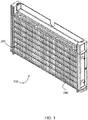
- Evaporator assembly 100 includes evaporator 110 and an evaporator housing formed by housing top 140, bottom 150, sides 160 and 170, and back 180.
- the top 140, bottom 150, sides 160 and 170, and back 180 of the evaporator housing are plastic.
- the top 140, bottom 150, sides 160 and 170, and back 180 of the evaporator housing may have features allowing them to be assembled together in a variety of ways, including snap-fit features, bolts and nuts, etc.
- the inner surfaces of the top 140, bottom 150, sides 160 and 170 may include a gasket material to aid in sealing the evaporator housing water tight.
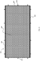
- Evaporator 110 includes an evaporator pan 120 having a back wall 300 and a left sidewall 310, a right sidewall 320, a top sidewall 330, and a bottom sidewall 340 extending from back wall 300 toward the front side of evaporator 110.
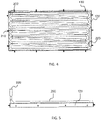
- Left, right, and top sidewalls 310, 330, 320, are substantially perpendicular to back wall 300 while bottom sidewall 340 preferably angles slightly downward.
- the evaporator pan 120 includes a series of studs 130 that may be used to mount evaporator assembly 100 to an internal structure of the ice maker (not shown).
- the evaporator housing may have corresponding mating openings 190, through which the studs 130 may pass.
- a population of vertical and horizontal strips 240, 250 are secured in evaporator pan 120 to form a lattice of ice cube "molds."
- Evaporator pan 120 with vertical and horizontal strips 240, 250 may also be called a freeze plate.
- Attached to the back side of back wall 300 of evaporator pan 120 is a serpentine tube 200 through which cold refrigerant flows to lower the temperature of evaporator 110 so that ice can be formed therein.
- Serpentine tube 200 includes inlet tube 220 and outlet tube 210 which extend through evaporator assembly 100, as described more fully elsewhere herein. Locating the inlet tube 220 at the bottom of the evaporator assembly 100 assists in ensuring an even distribution of temperature across the evaporator.
- the serpentine tube 200 may be attached to the back side of back wall 300 of the evaporator pan 120 in a number of conventional ways, including using a soldering or brazing process.
- the components of evaporator 110 are preferably formed of copper. To satisfy the water contact cleanliness requirements of NSF for commercial ice machines, all areas of evaporator 110 that are considered to be in the "food zone" of the ice maker cannot be bare copper and thus must be plated. Any portion of evaporator 110 that could potentially drip water into the food zone is considered to be inside the food zone and must comply with this requirement. Because of this requirement, typical ice machine evaporators must be completely plated such that no un-plated, bare copper surfaces are exposed. Typical evaporators are exposed on all sides, thus the entire surface of typical evaporators - front and back - must be plated.
- This plating typically a thin layer of electroless nickel (EN), is quite expensive, costing roughly as much as the rest of the evaporator.
- EN electroless nickel
- the back side of evaporator 110 does not need to be plated.
- the front side of back wall 300, sidewalls 310, 320, 330, and 340 of evaporator pan 120 are plated.
- the back side of back wall 300 and serpentine tubing 200 are not required to be plated.
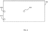
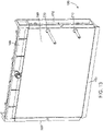
- passageways 610, 620 extend through back wall 180 of evaporator housing.
- Passageways 610, 620 permit inlet and outlet tubes 220, 210, respectively, of serpentine tube 200 to pass through back wall 300 of the evaporator housing such that serpentine tube 200 can be coupled with the remaining components of the refrigeration system of an ice maker (not shown).
- Passageways 610, 620 are preferably circular in shape; however, passageways may be rectangular, square, ovular, etc. without departing from the scope of the invention.
- Rubber grommets may be inserted into passageways 610, 620 to seal any gap between passageways 610, 620 and inlet and outlet tubes 220, 210, respectively, of serpentine tube 200.
- a caulk or sealant may be used in addition to or in place of grommets to seal any gap between passageways 610, 620 and inlet and outlet tubes 220, 210.
- a third passageway 630 may be provided in the back wall 180 in order to inject insulating material into the interior of the evaporator housing assembly 100 as described below.
- the evaporator assembly 100 further includes an insulating material 710 layered over at least a majority of the length of the serpentine tube 200.
- the insulating material 710 minimizes the amount of heat dissipated by the serpentine tube 200 and provides a water-tight seal.
- the insulating material 710 is a heavy-bodied, water-based, vinyl acrylic, general-purpose mastic that is typically used in both interior and exterior insulation systems.
- Examples of insulating material 710 include two-part silicone materials such as QSil 550 from Quantum Silicones LLC of Richmond, VA.
- the insulating material 710 is applied in liquid form onto the serpentine tubing 200 to a thickness of approximately about 5 mm to about 12 mm.
- the insulating material 710 then cures, forming an integral layer of insulation that is impervious to water.
- the integral layer of insulation has no joints through which water can leak, will not rust, and adds rigidity and strength.
- the insulating material 710 is poured in a liquid form, it cures into a mold that matches the geometry of the serpentine tubing 340 and can fill in all gaps within the back side of the evaporator pan.
- the evaporator assembly 100 may be assembled.
- the five components of the evaporator housing namely housing top 140, bottom 150, sides 160 and 170, and back 180 may be assembled together surrounding the evaporator pan 110 in order to form the complete assembly 100.
- Forming the assembly results in a cavity formed between the back side of evaporator 110 (holding the serpentine tube 200) and the front side of back wall 180 of evaporator housing, and further enclosed by the housing top 140, bottom 150 and sides 160 and 170.
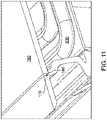
- the back 180 may include one or more raised edges 182, 184, 186, and 188. As shown in FIGs. 9 and 10 , the raised edges 182, 184, 186, and 188 preferably surround the perimeter of the back 180. The raised edges 182, 184, 186, and 188 extend outwardly away from the inner surface of the back 180 ( i.e. , the surface facing the serpentine tube 200). As shown in FIGs. 11 and 12 , the raised edges 182, 184, 186, and 188 initially rest within grooves 172, 174, 176, and 178 formed in the top 140, bottom 150, and sides 160 and 170.
- the back 180 may then be ultrasonically welded to the top 140, bottom 150, and sides 160 and 170 in order to seal the entire assembly together as shown in Fig. 13 .
- the raised edges 182, 184, 186, and 188 which may be a raised triangular bead of material molded onto the surface of the back 180, concentrate the ultrasonic energy to rapidly initiate the softening and melting of the surface of the back 180 and grooves 172, 174, 176, and 178 as is known to those skilled in the art of ultrasonic welding. During welding, the raised edges 182, 184, 186, and 188 melt flat to seal the back 180 into the grooves 172, 174, 176, and 178.
- the cavity may be filled with foam after evaporator assembly 100 is assembled.
- the foam may be open- or closed-cell foam comprised, for example, of polystyrene or polyurethane, etc.
- the foam is an expanding-type foam that can be sprayed into the cavity through passage 630.
- the foam preferably conforms to the back side of evaporator 110 so that it covers all or substantially all of the back side of evaporator pan 120 and the insulated serpentine tube 200 and fills all or substantially all of cavity.
- the foam may be sprayed into cavity after evaporator 110 and evaporator housing are assembled together.
- Another acceptable form is a two-part liquid form sold under the brand name Ecomate, in which the two parts mix and cure in place.
- a plug (not shown) may be inserted into or over the passageway 630 and may be held and sealed in place by the foam inside cavity. Additionally or alternatively, the plug may be held in by any type of sealant and/or adhesive, including, but not limited to, silicone caulk.
- the insulating material 710 may be applied to a thicker layer.
- the increase in insulation effectively allows one to reduce the size of the evaporator 110, thus minimizing the size of the required compressor and condenser for the identical ice making capacity.
- an icemaker can achieve slightly larger amounts of produced ice using significantly less energy.
Landscapes
- Engineering & Computer Science (AREA)
- Mechanical Engineering (AREA)
- Physics & Mathematics (AREA)
- Thermal Sciences (AREA)
- General Engineering & Computer Science (AREA)
- Production, Working, Storing, Or Distribution Of Ice (AREA)
- Apparatus For Making Beverages (AREA)
- Devices That Are Associated With Refrigeration Equipment (AREA)
- Packages (AREA)
Applications Claiming Priority (3)
| Application Number | Priority Date | Filing Date | Title |
|---|---|---|---|
| US201662425905P | 2016-11-23 | 2016-11-23 | |
| PCT/US2017/062683 WO2018098110A1 (en) | 2016-11-23 | 2017-11-21 | Sanitary evaporator assembly |
| EP17873275.6A EP3545244B1 (de) | 2016-11-23 | 2017-11-21 | Sanitärverdampfungsanordnung |
Related Parent Applications (1)
| Application Number | Title | Priority Date | Filing Date |
|---|---|---|---|
| EP17873275.6A Division EP3545244B1 (de) | 2016-11-23 | 2017-11-21 | Sanitärverdampfungsanordnung |
Publications (3)
| Publication Number | Publication Date |
|---|---|
| EP4001801A1 true EP4001801A1 (de) | 2022-05-25 |
| EP4001801C0 EP4001801C0 (de) | 2025-07-09 |
| EP4001801B1 EP4001801B1 (de) | 2025-07-09 |
Family
ID=62147495
Family Applications (2)
| Application Number | Title | Priority Date | Filing Date |
|---|---|---|---|
| EP22150246.1A Active EP4001801B1 (de) | 2016-11-23 | 2017-11-21 | Sanitärverdampfungsanordnung |
| EP17873275.6A Active EP3545244B1 (de) | 2016-11-23 | 2017-11-21 | Sanitärverdampfungsanordnung |
Family Applications After (1)
| Application Number | Title | Priority Date | Filing Date |
|---|---|---|---|
| EP17873275.6A Active EP3545244B1 (de) | 2016-11-23 | 2017-11-21 | Sanitärverdampfungsanordnung |
Country Status (11)
| Country | Link |
|---|---|
| US (6) | US10571180B2 (de) |
| EP (2) | EP4001801B1 (de) |
| JP (1) | JP7062679B2 (de) |
| KR (1) | KR102397785B1 (de) |
| CN (2) | CN113701414B (de) |
| AU (1) | AU2017363597B2 (de) |
| CA (1) | CA3043219A1 (de) |
| ES (2) | ES3040623T3 (de) |
| MX (3) | MX2019005481A (de) |
| MY (1) | MY193626A (de) |
| WO (1) | WO2018098110A1 (de) |
Families Citing this family (20)
| Publication number | Priority date | Publication date | Assignee | Title |
|---|---|---|---|---|
| US11025034B2 (en) * | 2016-08-31 | 2021-06-01 | Nlight, Inc. | Laser cooling system |
| EP4001801B1 (de) * | 2016-11-23 | 2025-07-09 | True Manufacturing Co., Inc. | Sanitärverdampfungsanordnung |
| CN112119546B (zh) | 2018-03-12 | 2024-03-26 | 恩耐公司 | 具有可变盘绕光纤的光纤激光器 |
| CN110793247B (zh) * | 2018-08-03 | 2022-07-26 | 星崎美国公司 | 制冰机 |
| US11255588B2 (en) | 2018-08-03 | 2022-02-22 | Hoshizaki America, Inc. | Ultrasonic bin control in an ice machine |
| EP3604984B1 (de) * | 2018-08-03 | 2024-03-06 | Hoshizaki America, Inc. | Eiserzeuger und verfahren zur herstellung eines eiserzeugers |
| KR102622740B1 (ko) * | 2019-03-25 | 2024-01-10 | 삼성전자주식회사 | 냉장고 |
| US11802727B2 (en) | 2020-01-18 | 2023-10-31 | True Manufacturing Co., Inc. | Ice maker |
| US11913699B2 (en) | 2020-01-18 | 2024-02-27 | True Manufacturing Co., Inc. | Ice maker |
| US11602059B2 (en) | 2020-01-18 | 2023-03-07 | True Manufacturing Co., Inc. | Refrigeration appliance with detachable electronics module |
| US11391500B2 (en) | 2020-01-18 | 2022-07-19 | True Manufacturing Co., Inc. | Ice maker |
| US11255589B2 (en) | 2020-01-18 | 2022-02-22 | True Manufacturing Co., Inc. | Ice maker |
| US11578905B2 (en) | 2020-01-18 | 2023-02-14 | True Manufacturing Co., Inc. | Ice maker, ice dispensing assembly, and method of deploying ice maker |
| US11656017B2 (en) | 2020-01-18 | 2023-05-23 | True Manufacturing Co., Inc. | Ice maker |
| US11519652B2 (en) | 2020-03-18 | 2022-12-06 | True Manufacturing Co., Inc. | Ice maker |
| US11674731B2 (en) | 2021-01-13 | 2023-06-13 | True Manufacturing Co., Inc. | Ice maker |
| JP7737162B2 (ja) * | 2021-03-22 | 2025-09-10 | 株式会社アドテックス | 冷凍回路 |
| US11686519B2 (en) | 2021-07-19 | 2023-06-27 | True Manufacturing Co., Inc. | Ice maker with pulsed fill routine |
| JP2023031674A (ja) * | 2021-08-25 | 2023-03-09 | 東プレ株式会社 | 冷凍板 |
| US20230384004A1 (en) * | 2022-05-27 | 2023-11-30 | Starion Sungchull Co., Ltd. | Concave-convex evaporator |
Citations (4)
| Publication number | Priority date | Publication date | Assignee | Title |
|---|---|---|---|---|
| US4733539A (en) * | 1986-12-04 | 1988-03-29 | Schneider Metal Manufacturing Co. | Ice cube maker with new freeze and harvest control |
| JPH11297286A (ja) * | 1998-04-15 | 1999-10-29 | Fuji Photo Film Co Ltd | バッテリーパックの組立て方法 |
| US6145336A (en) * | 1999-05-03 | 2000-11-14 | Manitowoc Foodservice Group, Inc. | Plastic evaporator mount with two step molding |
| US20160146524A1 (en) * | 2011-06-22 | 2016-05-26 | Whirlpool Corporation | Vertical ice maker producing clear ice pieces |
Family Cites Families (32)
| Publication number | Priority date | Publication date | Assignee | Title |
|---|---|---|---|---|
| US2741095A (en) | 1952-10-07 | 1956-04-10 | Gen Motors Corp | Refrigeratior having multiple section evaporator |
| US4344299A (en) | 1980-08-05 | 1982-08-17 | Latzer John B | Transportable compartment refrigeration panel system and method of installing |
| JPS60217276A (ja) * | 1984-04-11 | 1985-10-30 | Mitsubishi Heavy Ind Ltd | 藻類防除、防食処理の方法 |
| JPS616560A (ja) * | 1984-06-19 | 1986-01-13 | 松下冷機株式会社 | 蒸発器 |
| JPS6134202A (ja) | 1984-07-20 | 1986-02-18 | 花王株式会社 | シ−トに弾性材を取付ける方法 |
| US4733549A (en) | 1987-05-08 | 1988-03-29 | Baker Franklin W | Theft preventing luggage handle attachment |
| US4949554A (en) | 1989-09-08 | 1990-08-21 | Specialty Equipment Companies, Inc. | Single pane, curved glass lid, frozen food merchandiser |
| US5182925A (en) | 1991-05-13 | 1993-02-02 | Mile High Equipment Company | Integrally formed, modular ice cuber having a stainless steel evaporator and microcontroller |
| JPH05312447A (ja) * | 1992-05-08 | 1993-11-22 | Matsushita Refrig Co Ltd | 冷蔵庫の自動製氷装置 |
| JPH09310944A (ja) * | 1996-05-21 | 1997-12-02 | Sanyo Electric Co Ltd | セル型製氷機の水皿 |
| ES2242259T3 (es) * | 1997-04-22 | 2005-11-01 | Manitowoc Foodservice Companies, Inc. | Conjunto de deposito para hielo. |
| AU1449000A (en) * | 1998-10-20 | 2000-05-08 | John A. Broadbent | Low cost ice making evaporator |
| CN2364412Y (zh) | 1998-12-08 | 2000-02-16 | 海尔集团公司 | 一种带有冷冻间室的冷藏箱 |
| CN2426118Y (zh) * | 2000-07-03 | 2001-04-04 | 蔡锡然 | 冰粒机用中空型冷凝板装置 |
| GB0114579D0 (en) | 2001-06-15 | 2001-08-08 | Rothwell Andrew J | Brazed heat transfer element |
| US6564563B2 (en) * | 2001-06-29 | 2003-05-20 | International Business Machines Corporation | Logic module refrigeration system with condensation control |
| CN1759282A (zh) * | 2003-03-07 | 2006-04-12 | 斯科茨曼制冰系统公司 | 改进传热的制冰机蒸发器组件及其制造方法 |
| US6964177B2 (en) * | 2003-05-28 | 2005-11-15 | Lg Electronics Inc. | Refrigerator with icemaker |
| JP2005134019A (ja) * | 2003-10-29 | 2005-05-26 | Hoshizaki Electric Co Ltd | 縦型製氷機の製氷部 |
| TWI335407B (en) * | 2003-12-19 | 2011-01-01 | Hoshizaki Electric Co Ltd | Automatic ice making machine |
| JP2006162163A (ja) | 2004-12-08 | 2006-06-22 | Matsushita Electric Ind Co Ltd | 低温貯蔵庫 |
| EP1899665A4 (de) * | 2005-06-22 | 2015-01-07 | Manitowoc Foodservice Co Inc | Eisherstellungsmaschine, verdampferanordnung für eine eisherstellungsmaschine und verfahren zur herstellung derselben |
| US20070101753A1 (en) * | 2005-10-06 | 2007-05-10 | Mile High Equipment Llc | Thermally conductive ice-forming surfaces incorporating short-duration electro-thermal deicing |
| JP4764136B2 (ja) | 2005-10-31 | 2011-08-31 | 富士通セミコンダクター株式会社 | 動画像符号化装置、及びフェードシーン検出装置 |
| FR2893705B1 (fr) | 2005-11-23 | 2007-12-21 | Brandt Ind Sas | Bac a glacons, notamment pour appareil electromenager du type refrigerateur |
| US8250881B1 (en) | 2006-11-21 | 2012-08-28 | Michael Reihl | Method and apparatus for controlling temperature of a temperature maintenance storage unit |
| US8919145B2 (en) * | 2011-06-22 | 2014-12-30 | Whirlpool Corporation | Vertical ice maker with microchannel evaporator |
| GB2496948B (en) | 2011-10-19 | 2014-10-15 | Thermo Fisher Scient Asheville | High performance refrigerator having insulated evaporator cover |
| US20130340462A1 (en) * | 2012-06-22 | 2013-12-26 | Jeffrey L. Bush | Ice bar system |
| CN205298959U (zh) * | 2015-12-08 | 2016-06-08 | 朗格斯特哈尔滨环保节能产品制造有限公司 | 具有波纹外护管的保温管 |
| CN106369882B (zh) | 2016-08-25 | 2019-02-22 | 安徽江淮松芝空调有限公司 | 一种蒸发器双层保温结构 |
| EP4001801B1 (de) * | 2016-11-23 | 2025-07-09 | True Manufacturing Co., Inc. | Sanitärverdampfungsanordnung |
-
2017
- 2017-11-21 EP EP22150246.1A patent/EP4001801B1/de active Active
- 2017-11-21 CN CN202110858862.8A patent/CN113701414B/zh active Active
- 2017-11-21 US US15/819,132 patent/US10571180B2/en active Active
- 2017-11-21 MX MX2019005481A patent/MX2019005481A/es unknown
- 2017-11-21 KR KR1020197017430A patent/KR102397785B1/ko active Active
- 2017-11-21 AU AU2017363597A patent/AU2017363597B2/en not_active Ceased
- 2017-11-21 WO PCT/US2017/062683 patent/WO2018098110A1/en not_active Ceased
- 2017-11-21 CN CN201780072344.5A patent/CN110114625B/zh active Active
- 2017-11-21 CA CA3043219A patent/CA3043219A1/en active Pending
- 2017-11-21 EP EP17873275.6A patent/EP3545244B1/de active Active
- 2017-11-21 JP JP2019547591A patent/JP7062679B2/ja active Active
- 2017-11-21 ES ES22150246T patent/ES3040623T3/es active Active
- 2017-11-21 ES ES17873275T patent/ES2910978T3/es active Active
- 2017-11-21 MY MYPI2019002852A patent/MY193626A/en unknown
-
2019
- 2019-05-09 MX MX2022013123A patent/MX2022013123A/es unknown
- 2019-05-09 MX MX2022013122A patent/MX2022013122A/es unknown
-
2020
- 2020-01-18 US US16/746,823 patent/US11054180B2/en active Active
-
2021
- 2021-05-13 US US17/319,209 patent/US11668507B2/en active Active
-
2023
- 2023-03-03 US US18/178,322 patent/US11821669B2/en active Active
- 2023-11-14 US US18/508,281 patent/US12117224B2/en active Active
-
2024
- 2024-09-13 US US18/884,358 patent/US20250020381A1/en active Pending
Patent Citations (4)
| Publication number | Priority date | Publication date | Assignee | Title |
|---|---|---|---|---|
| US4733539A (en) * | 1986-12-04 | 1988-03-29 | Schneider Metal Manufacturing Co. | Ice cube maker with new freeze and harvest control |
| JPH11297286A (ja) * | 1998-04-15 | 1999-10-29 | Fuji Photo Film Co Ltd | バッテリーパックの組立て方法 |
| US6145336A (en) * | 1999-05-03 | 2000-11-14 | Manitowoc Foodservice Group, Inc. | Plastic evaporator mount with two step molding |
| US20160146524A1 (en) * | 2011-06-22 | 2016-05-26 | Whirlpool Corporation | Vertical ice maker producing clear ice pieces |
Also Published As
Similar Documents
| Publication | Publication Date | Title |
|---|---|---|
| US11821669B2 (en) | Sanitary evaporator assembly | |
| EP3343132B1 (de) | Verdampferanordnung für eisherstellungsvorrichtung und -verfahren | |
| KR20180013539A (ko) | 증발기 및 이를 구비하는 냉장고 | |
| JP2005090814A (ja) | 噴射式製氷機 | |
| HK40005634A (en) | Sanitary evaporator assembly | |
| HK40005634B (zh) | 清洁的蒸发器总成 | |
| BR112019010347B1 (pt) | Conjunto de evaporador e método para formar um conjunto de evaporador para uma máquina de gelo | |
| KR101266445B1 (ko) | 제빙유닛의 침지돌기 | |
| JPH0328305Y2 (de) | ||
| JPH06129754A (ja) | 除霜水排出装置 | |
| JP2003114085A (ja) | 冷蔵庫 | |
| EP3867580B1 (de) | Eine verdampferanordnung für eine eisherstellungsmaschine mit vertikalem durschfluss | |
| KR20140117793A (ko) | 제빙장치 | |
| JP3978041B2 (ja) | 冷却貯蔵庫 | |
| JP2003148858A (ja) | 冷却貯蔵庫 | |
| JPH09178325A (ja) | 冷水機 |
Legal Events
| Date | Code | Title | Description |
|---|---|---|---|
| PUAI | Public reference made under article 153(3) epc to a published international application that has entered the european phase |
Free format text: ORIGINAL CODE: 0009012 |
|
| STAA | Information on the status of an ep patent application or granted ep patent |
Free format text: STATUS: THE APPLICATION HAS BEEN PUBLISHED |
|
| AC | Divisional application: reference to earlier application |
Ref document number: 3545244 Country of ref document: EP Kind code of ref document: P |
|
| AK | Designated contracting states |
Kind code of ref document: A1 Designated state(s): AL AT BE BG CH CY CZ DE DK EE ES FI FR GB GR HR HU IE IS IT LI LT LU LV MC MK MT NL NO PL PT RO RS SE SI SK SM TR |
|
| STAA | Information on the status of an ep patent application or granted ep patent |
Free format text: STATUS: REQUEST FOR EXAMINATION WAS MADE |
|
| 17P | Request for examination filed |
Effective date: 20221116 |
|
| RBV | Designated contracting states (corrected) |
Designated state(s): AL AT BE BG CH CY CZ DE DK EE ES FI FR GB GR HR HU IE IS IT LI LT LU LV MC MK MT NL NO PL PT RO RS SE SI SK SM TR |
|
| GRAP | Despatch of communication of intention to grant a patent |
Free format text: ORIGINAL CODE: EPIDOSNIGR1 |
|
| STAA | Information on the status of an ep patent application or granted ep patent |
Free format text: STATUS: GRANT OF PATENT IS INTENDED |
|
| INTG | Intention to grant announced |
Effective date: 20240830 |
|
| GRAJ | Information related to disapproval of communication of intention to grant by the applicant or resumption of examination proceedings by the epo deleted |
Free format text: ORIGINAL CODE: EPIDOSDIGR1 |
|
| STAA | Information on the status of an ep patent application or granted ep patent |
Free format text: STATUS: REQUEST FOR EXAMINATION WAS MADE |
|
| GRAP | Despatch of communication of intention to grant a patent |
Free format text: ORIGINAL CODE: EPIDOSNIGR1 |
|
| STAA | Information on the status of an ep patent application or granted ep patent |
Free format text: STATUS: GRANT OF PATENT IS INTENDED |
|
| INTC | Intention to grant announced (deleted) | ||
| INTG | Intention to grant announced |
Effective date: 20250131 |
|
| GRAS | Grant fee paid |
Free format text: ORIGINAL CODE: EPIDOSNIGR3 |
|
| GRAA | (expected) grant |
Free format text: ORIGINAL CODE: 0009210 |
|
| STAA | Information on the status of an ep patent application or granted ep patent |
Free format text: STATUS: THE PATENT HAS BEEN GRANTED |
|
| AC | Divisional application: reference to earlier application |
Ref document number: 3545244 Country of ref document: EP Kind code of ref document: P |
|
| AK | Designated contracting states |
Kind code of ref document: B1 Designated state(s): AL AT BE BG CH CY CZ DE DK EE ES FI FR GB GR HR HU IE IS IT LI LT LU LV MC MK MT NL NO PL PT RO RS SE SI SK SM TR |
|
| REG | Reference to a national code |
Ref country code: GB Ref legal event code: FG4D |
|
| REG | Reference to a national code |
Ref country code: CH Ref legal event code: EP |
|
| REG | Reference to a national code |
Ref country code: IE Ref legal event code: FG4D |
|
| REG | Reference to a national code |
Ref country code: DE Ref legal event code: R096 Ref document number: 602017090545 Country of ref document: DE |
|
| U01 | Request for unitary effect filed |
Effective date: 20250717 |
|
| U07 | Unitary effect registered |
Designated state(s): AT BE BG DE DK EE FI FR IT LT LU LV MT NL PT RO SE SI Effective date: 20250724 |
|
| REG | Reference to a national code |
Ref country code: ES Ref legal event code: FG2A Ref document number: 3040623 Country of ref document: ES Kind code of ref document: T3 Effective date: 20251103 |
|
| U20 | Renewal fee for the european patent with unitary effect paid |
Year of fee payment: 9 Effective date: 20251126 |
|
| PG25 | Lapsed in a contracting state [announced via postgrant information from national office to epo] |
Ref country code: IS Free format text: LAPSE BECAUSE OF FAILURE TO SUBMIT A TRANSLATION OF THE DESCRIPTION OR TO PAY THE FEE WITHIN THE PRESCRIBED TIME-LIMIT Effective date: 20251109 |
|
| PGFP | Annual fee paid to national office [announced via postgrant information from national office to epo] |
Ref country code: GB Payment date: 20251127 Year of fee payment: 9 |
|
| PG25 | Lapsed in a contracting state [announced via postgrant information from national office to epo] |
Ref country code: NO Free format text: LAPSE BECAUSE OF FAILURE TO SUBMIT A TRANSLATION OF THE DESCRIPTION OR TO PAY THE FEE WITHIN THE PRESCRIBED TIME-LIMIT Effective date: 20251009 |
|
| PG25 | Lapsed in a contracting state [announced via postgrant information from national office to epo] |
Ref country code: HR Free format text: LAPSE BECAUSE OF FAILURE TO SUBMIT A TRANSLATION OF THE DESCRIPTION OR TO PAY THE FEE WITHIN THE PRESCRIBED TIME-LIMIT Effective date: 20250709 |
|
| PG25 | Lapsed in a contracting state [announced via postgrant information from national office to epo] |
Ref country code: GR Free format text: LAPSE BECAUSE OF FAILURE TO SUBMIT A TRANSLATION OF THE DESCRIPTION OR TO PAY THE FEE WITHIN THE PRESCRIBED TIME-LIMIT Effective date: 20251010 |
|
| PG25 | Lapsed in a contracting state [announced via postgrant information from national office to epo] |
Ref country code: PL Free format text: LAPSE BECAUSE OF FAILURE TO SUBMIT A TRANSLATION OF THE DESCRIPTION OR TO PAY THE FEE WITHIN THE PRESCRIBED TIME-LIMIT Effective date: 20250709 |
|
| PG25 | Lapsed in a contracting state [announced via postgrant information from national office to epo] |
Ref country code: RS Free format text: LAPSE BECAUSE OF FAILURE TO SUBMIT A TRANSLATION OF THE DESCRIPTION OR TO PAY THE FEE WITHIN THE PRESCRIBED TIME-LIMIT Effective date: 20251009 |
|
| PGFP | Annual fee paid to national office [announced via postgrant information from national office to epo] |
Ref country code: ES Payment date: 20251201 Year of fee payment: 9 |
|
| PG25 | Lapsed in a contracting state [announced via postgrant information from national office to epo] |
Ref country code: SM Free format text: LAPSE BECAUSE OF FAILURE TO SUBMIT A TRANSLATION OF THE DESCRIPTION OR TO PAY THE FEE WITHIN THE PRESCRIBED TIME-LIMIT Effective date: 20250709 |
|
| PG25 | Lapsed in a contracting state [announced via postgrant information from national office to epo] |
Ref country code: CZ Free format text: LAPSE BECAUSE OF FAILURE TO SUBMIT A TRANSLATION OF THE DESCRIPTION OR TO PAY THE FEE WITHIN THE PRESCRIBED TIME-LIMIT Effective date: 20250709 |
|
| PG25 | Lapsed in a contracting state [announced via postgrant information from national office to epo] |
Ref country code: SK Free format text: LAPSE BECAUSE OF FAILURE TO SUBMIT A TRANSLATION OF THE DESCRIPTION OR TO PAY THE FEE WITHIN THE PRESCRIBED TIME-LIMIT Effective date: 20250709 |