EP4003692B1 - Schliesseinheit für eine blasformmaschine - Google Patents
Schliesseinheit für eine blasformmaschine Download PDFInfo
- Publication number
- EP4003692B1 EP4003692B1 EP20788723.3A EP20788723A EP4003692B1 EP 4003692 B1 EP4003692 B1 EP 4003692B1 EP 20788723 A EP20788723 A EP 20788723A EP 4003692 B1 EP4003692 B1 EP 4003692B1
- Authority
- EP
- European Patent Office
- Prior art keywords
- actuator
- clamping unit
- mould
- tool
- actuators
- Prior art date
- Legal status (The legal status is an assumption and is not a legal conclusion. Google has not performed a legal analysis and makes no representation as to the accuracy of the status listed.)
- Active
Links
Images


Classifications
-
- B—PERFORMING OPERATIONS; TRANSPORTING
- B29—WORKING OF PLASTICS; WORKING OF SUBSTANCES IN A PLASTIC STATE IN GENERAL
- B29C—SHAPING OR JOINING OF PLASTICS; SHAPING OF MATERIAL IN A PLASTIC STATE, NOT OTHERWISE PROVIDED FOR; AFTER-TREATMENT OF THE SHAPED PRODUCTS, e.g. REPAIRING
- B29C49/00—Blow-moulding, i.e. blowing a preform or parison to a desired shape within a mould; Apparatus therefor
- B29C49/42—Component parts, details or accessories; Auxiliary operations
- B29C49/48—Moulds
- B29C49/54—Moulds for undercut articles
-
- B—PERFORMING OPERATIONS; TRANSPORTING
- B29—WORKING OF PLASTICS; WORKING OF SUBSTANCES IN A PLASTIC STATE IN GENERAL
- B29C—SHAPING OR JOINING OF PLASTICS; SHAPING OF MATERIAL IN A PLASTIC STATE, NOT OTHERWISE PROVIDED FOR; AFTER-TREATMENT OF THE SHAPED PRODUCTS, e.g. REPAIRING
- B29C49/00—Blow-moulding, i.e. blowing a preform or parison to a desired shape within a mould; Apparatus therefor
- B29C49/02—Combined blow-moulding and manufacture of the preform or the parison
- B29C49/04—Extrusion blow-moulding
-
- B—PERFORMING OPERATIONS; TRANSPORTING
- B29—WORKING OF PLASTICS; WORKING OF SUBSTANCES IN A PLASTIC STATE IN GENERAL
- B29C—SHAPING OR JOINING OF PLASTICS; SHAPING OF MATERIAL IN A PLASTIC STATE, NOT OTHERWISE PROVIDED FOR; AFTER-TREATMENT OF THE SHAPED PRODUCTS, e.g. REPAIRING
- B29C49/00—Blow-moulding, i.e. blowing a preform or parison to a desired shape within a mould; Apparatus therefor
- B29C49/42—Component parts, details or accessories; Auxiliary operations
- B29C49/56—Opening, closing or clamping means
- B29C49/5605—Hydraulically operated, i.e. closing or opening of the mould parts is done by hydraulic means
-
- B—PERFORMING OPERATIONS; TRANSPORTING
- B29—WORKING OF PLASTICS; WORKING OF SUBSTANCES IN A PLASTIC STATE IN GENERAL
- B29C—SHAPING OR JOINING OF PLASTICS; SHAPING OF MATERIAL IN A PLASTIC STATE, NOT OTHERWISE PROVIDED FOR; AFTER-TREATMENT OF THE SHAPED PRODUCTS, e.g. REPAIRING
- B29C49/00—Blow-moulding, i.e. blowing a preform or parison to a desired shape within a mould; Apparatus therefor
- B29C49/42—Component parts, details or accessories; Auxiliary operations
- B29C49/48—Moulds
- B29C2049/4856—Mounting, exchanging or centering moulds or parts thereof
- B29C2049/4858—Exchanging mould parts, e.g. for changing the mould size or geometry for making different products in the same mould
-
- B—PERFORMING OPERATIONS; TRANSPORTING
- B29—WORKING OF PLASTICS; WORKING OF SUBSTANCES IN A PLASTIC STATE IN GENERAL
- B29C—SHAPING OR JOINING OF PLASTICS; SHAPING OF MATERIAL IN A PLASTIC STATE, NOT OTHERWISE PROVIDED FOR; AFTER-TREATMENT OF THE SHAPED PRODUCTS, e.g. REPAIRING
- B29C49/00—Blow-moulding, i.e. blowing a preform or parison to a desired shape within a mould; Apparatus therefor
- B29C49/42—Component parts, details or accessories; Auxiliary operations
- B29C49/48—Moulds
- B29C2049/4879—Moulds characterised by mould configurations
- B29C2049/4892—Mould halves consisting of an independent main and bottom part
-
- B—PERFORMING OPERATIONS; TRANSPORTING
- B29—WORKING OF PLASTICS; WORKING OF SUBSTANCES IN A PLASTIC STATE IN GENERAL
- B29C—SHAPING OR JOINING OF PLASTICS; SHAPING OF MATERIAL IN A PLASTIC STATE, NOT OTHERWISE PROVIDED FOR; AFTER-TREATMENT OF THE SHAPED PRODUCTS, e.g. REPAIRING
- B29C49/00—Blow-moulding, i.e. blowing a preform or parison to a desired shape within a mould; Apparatus therefor
- B29C49/42—Component parts, details or accessories; Auxiliary operations
- B29C49/48—Moulds
- B29C49/54—Moulds for undercut articles
- B29C2049/542—Moulds for undercut articles having means to facilitate the removal of the blow moulded articles
- B29C2049/546—Moulds for undercut articles having means to facilitate the removal of the blow moulded articles by translatorilly actuating an auxiliary mould part while the mould is still in a closed position
-
- B—PERFORMING OPERATIONS; TRANSPORTING
- B29—WORKING OF PLASTICS; WORKING OF SUBSTANCES IN A PLASTIC STATE IN GENERAL
- B29C—SHAPING OR JOINING OF PLASTICS; SHAPING OF MATERIAL IN A PLASTIC STATE, NOT OTHERWISE PROVIDED FOR; AFTER-TREATMENT OF THE SHAPED PRODUCTS, e.g. REPAIRING
- B29C49/00—Blow-moulding, i.e. blowing a preform or parison to a desired shape within a mould; Apparatus therefor
- B29C49/42—Component parts, details or accessories; Auxiliary operations
- B29C49/56—Opening, closing or clamping means
- B29C2049/566—Locking means
- B29C2049/5661—Mechanical
-
- B—PERFORMING OPERATIONS; TRANSPORTING
- B29—WORKING OF PLASTICS; WORKING OF SUBSTANCES IN A PLASTIC STATE IN GENERAL
- B29C—SHAPING OR JOINING OF PLASTICS; SHAPING OF MATERIAL IN A PLASTIC STATE, NOT OTHERWISE PROVIDED FOR; AFTER-TREATMENT OF THE SHAPED PRODUCTS, e.g. REPAIRING
- B29C49/00—Blow-moulding, i.e. blowing a preform or parison to a desired shape within a mould; Apparatus therefor
- B29C49/28—Blow-moulding apparatus
- B29C49/28006—Blow-moulding apparatus having special frame
-
- B—PERFORMING OPERATIONS; TRANSPORTING
- B29—WORKING OF PLASTICS; WORKING OF SUBSTANCES IN A PLASTIC STATE IN GENERAL
- B29C—SHAPING OR JOINING OF PLASTICS; SHAPING OF MATERIAL IN A PLASTIC STATE, NOT OTHERWISE PROVIDED FOR; AFTER-TREATMENT OF THE SHAPED PRODUCTS, e.g. REPAIRING
- B29C49/00—Blow-moulding, i.e. blowing a preform or parison to a desired shape within a mould; Apparatus therefor
- B29C49/42—Component parts, details or accessories; Auxiliary operations
- B29C49/56—Opening, closing or clamping means
- B29C49/5601—Mechanically operated, i.e. closing or opening of the mould parts is done by mechanic means
- B29C49/5603—Mechanically operated, i.e. closing or opening of the mould parts is done by mechanic means using toggle mechanism
-
- B—PERFORMING OPERATIONS; TRANSPORTING
- B29—WORKING OF PLASTICS; WORKING OF SUBSTANCES IN A PLASTIC STATE IN GENERAL
- B29C—SHAPING OR JOINING OF PLASTICS; SHAPING OF MATERIAL IN A PLASTIC STATE, NOT OTHERWISE PROVIDED FOR; AFTER-TREATMENT OF THE SHAPED PRODUCTS, e.g. REPAIRING
- B29C49/00—Blow-moulding, i.e. blowing a preform or parison to a desired shape within a mould; Apparatus therefor
- B29C49/42—Component parts, details or accessories; Auxiliary operations
- B29C49/56—Opening, closing or clamping means
- B29C49/561—Characterised by speed, e.g. variable opening closing speed
-
- B—PERFORMING OPERATIONS; TRANSPORTING
- B29—WORKING OF PLASTICS; WORKING OF SUBSTANCES IN A PLASTIC STATE IN GENERAL
- B29L—INDEXING SCHEME ASSOCIATED WITH SUBCLASS B29C, RELATING TO PARTICULAR ARTICLES
- B29L2031/00—Other particular articles
- B29L2031/712—Containers; Packaging elements or accessories, Packages
- B29L2031/7158—Bottles
Definitions
- the disclosure relates to a clamping unit for a blow molding machine with a first and second mold carrier and a blow molding tool arranged on the clamping unit with two tool halves, each tool half being releasably attached to one of the two mold carriers and having an upper mold part and a lower mold part, the two tool halves between an open state and a closed state can be moved back and forth in a first direction of movement, the lower mold part of each tool half relative to the upper mold part of each tool half in a second direction of movement different from the first direction of movement between an open state and a closed state by means of at least one first or at least one second actuator and is movable and the blow molding tool delimits a mold cavity with undercuts when the two mold halves are closed when the two lower mold parts are also in the closed state.
- the disclosure relates to the production of hollow bodies by blow molding, in particular the production of containers made of plastic, such as canisters or bottles.
- blow molding for example, an extruder with a blow head produces a tubular preform, which is enclosed by the blow molding tool and with compressed air introduced by means of a blow mandrel is expanded in such a way that the hollow body in question receives the inner contour of the blow molding tool.
- the two tool halves can usually be moved towards one another in the horizontal direction by means of a clamping unit in order to open or close the blow molding tool.
- the structure of such a locking unit is, for example, in DE 102012 109 499 A1 disclosed.
- the containers to be manufactured can have depressions on the bottom and/or top, for example to form a curved container bottom or a grip area.
- the depressions represent an undercut compared to a lateral removal of the containers from the tool halves.
- two-part tool halves of a blow molding tool are known from the prior art, the lower bottom half of which can be lowered relative to an upper mold part of the tool half.
- the lower bottom half of each tool half is lowered separately via at least one hydraulic cylinder and then raised again for a new container manufacturing cycle.
- the disadvantage of the first blow molding tool is that two actuators are required per tool half and the width of the blow molding tool resulting from their arrangement can cause problems. With the second blow molding tool, changing the blow molding tool from the side is not possible.
- US 3,753,641 A discloses a system for producing bottles with a plurality of blow molding tools that are guided in a rotation path.
- Each blow molding tool consists of an outer mold half and an inner mold half.
- the outer mold half is guided on a circular cam track and, depending on the phase position on the cam track, can be moved towards the inner mold half in the radial direction or removed from the inner mold half in the radial direction.
- a mechanism with a double-actuated cylinder and a gear is arranged on each of the outer mold half and the inner mold half, which act on a movable mold end piece of the outer mold half or the inside mold half in order to move it.
- the mold end pieces are firmly connected to the mechanics via pin connections.
- the mechanism has a pair of rails for each mold end piece, which are firmly arranged on the respective mold half.
- the US 5,026,268 A discloses a blow molding system for the simultaneous blow molding of two plant pots, the edge areas of which are molded.
- Each tool half of the blow molding tool has a total of five molded parts.
- the two lower and upper mold parts of each mold half are rigidly connected to one another and in turn rigidly attached to a base of the respective mold half. This base is part of the blow molding tool and forms the frame of each of the two tool halves.
- a hydraulic cylinder is attached to this frame of the blow molding tool and is connected to the two lower mold parts via a piston rod.
- the firmly connected lower mold parts of each tool half are movable relative to a mold part lying between them in the direction of a guide rod connecting the mold parts.
- the mold part lying in between is movable in the direction of a further guide rod relative to the two upper mold parts firmly connected to the base of each mold half. This relative movement allows the edge area of the two planters to be molded.
- the actuators can be positioned on the machine side to optimize installation space in a space that is not usable or can only be used to a limited extent for the blow molding tool.
- the actuators are preferably arranged below the lower mold parts and are detachably connected to the underside of the respective lower mold part.
- the blow molding tool can be removed from the clamping unit laterally, that is, transversely to the closing direction of the two tool halves.
- the at least one first actuator and the at least one second actuator are arranged on the closing unit so that they can move relative to one another in the first direction of movement.
- a preferred embodiment of the invention provides that the at least one first actuator moves synchronously with the first mold carrier and the at least one second actuator moves synchronously with the second Mold carrier moves.
- the at least one first actuator can be arranged directly on the first mold carrier and the at least one second actuator can be arranged directly on the second mold carrier.
- a fastening console for indirectly fastening the at least one first actuator can be provided on the first mold carrier and a fastening console can be used on the second mold carrier indirect attachment of the at least one second actuator.
- a coupling rod or a support element can be considered as a coupling.
- a stationary guide present on the clamping unit, along which the first and second mold carriers are also slidably guided, can be used as a stationary longitudinal guide for the actuators.
- a separate, stationary longitudinal guide is provided for the actuators.
- the detachable connection By means of the detachable connection between the actuator and the lower part of the mold, a defined interface for power transmission is created.
- the detachable connection is designed in an advantageous embodiment of the invention as a coupling, which is used for the transmission of forces between the actuator and the lower mold part at least in the second Direction of movement, that is set up perpendicular to the horizontal closing and opening movement of the two tool halves.
- the clutch is preferably designed as a switchable, non-positive or positive clutch, for example as an electromagnetic clutch.
- the actuators are set up in such a way that they can move the lower mold part linearly back and forth between the open state and the closed state in the second direction of movement.
- the actuators can be designed as linear drives, in particular as fluid-operated working cylinders.
- the actuator is a slider crank mechanism that provides a rotary movement an oscillating thrust movement in the second direction of movement.
- the second direction of movement of the lower mold parts is usually perpendicular to the first direction of movement for opening and closing the blow molding tool, but can also run at a different angle depending on the hollow body to be produced.
- the clamping unit (1) of the present invention in particular the common drive for moving the mold carriers back and forth, the base frame with guides arranged thereon, the U-shaped frame elements and the synchronization device, reference is also made to the DE 10 2012 109 499 A1 Referenced.
- the Figures 1 - 3 show a first embodiment of the clamping unit 1 for a blow molding machine with a blow molding tool with two tool halves (2,3), each tool half (2,3) having an upper mold part (2.1, 3.1) and a lower mold part (2.2, 3.2).
- the tool half (2) is releasably attached to a first mold carrier (4) and the tool half (3) to a second mold carrier (5).
- the first mold carrier (4) is connected in an articulated manner to the two frame elements (6) of the clamping unit (1).
- the second form carrier (5) is connected to a drive (7) for moving the two mold carriers (4,5) and thus the tool halves (2,3) back and forth, the drive (7) also being supported on the frame elements (6).
- the closing unit (1) has a base frame which has side cheeks (9) arranged at a parallel distance from one another, on the upper edge of which a longitudinal guide (8) is arranged.
- the first and second mold carriers (4,5) and the drive (7) are connected to guide elements which are displaceably arranged on the longitudinal guides (8).
- a synchronization device (10) is also arranged on the base frame of the clamping unit (1), through which the closing and opening movement of the two tool halves (2, 3) takes place symmetrically in a first direction of movement (17).
- the Figures 1 - 3 show the two tool halves (2,3) in an open state.
- the lower mold parts (2.2, 3.2) are also in an open state.
- the two tool halves (2,3) and the respective upper and lower mold parts (2.1, 2.2 or 3.1, 3.2) lie against each other and delimit a mold cavity for producing a hollow body, in particular a canister.
- a fastening bracket (11, 12) is attached to the underside of the first mold carrier (4) and the second mold carrier (5).
- a first actuator (13) or a second actuator (14) is attached to each fastening console (11, 12) below the lower mold part (2.2, 3.2).
- the first actuator (13) is via a switchable clutch (15, 16). and the second actuator (14) can be releasably connected to the underside of the associated lower mold part (2.2, 3.2).
- the lower mold parts (2.2, 3.2) can be moved in a vertical direction relative to the upper mold parts (2.1, 3.1) of the two tool halves (2, 3) in a second direction of movement (18). to move the lower mold part (2.2, 3.2) of each tool half (2,3) back and forth between an open state and a closed state relative to the upper mold part (2.1) of the respective tool half (2,3).
- the second direction of movement (18) runs perpendicular to the first direction of movement (17).
- both the two upper mold parts (2.1,3.1) and the two lower mold parts (2.2,3.2) have mold areas which are designed to form depressions on the bottom and top of the hollow body to be produced. These mold areas require that the lower mold parts (2.2,3.2) be brought into an open state by means of the actuators (13,14) before the hollow body is removed from the mold.
- the mold clamping area is not affected. Furthermore, the couplings (15, 16) which engage on the underside of the lower mold parts (2.2, 3.2) facilitate changing the blow molding tool. Finally, the figures show that the production space for the hollow bodies is not restricted by the actuators (13, 14).
- FIGS 4 - 6 show a second embodiment of the clamping unit (1) for a blow molding machine with a blow molding tool, which is constructed with the clamping unit (1) according to Figures 1 - 3 largely agrees.
- Matching components and assemblies of the second embodiment are provided with the same reference numerals.
- the first actuator (13) moves synchronously with the first mold carrier (4)
- the second actuator (14) moves synchronously with the second mold carrier (5).
- the tool halves (2,3) are not shown in order to better show the components required for the synchronous movement.
- the locking unit (1) has a base frame which has side cheeks (9) arranged at a parallel distance from one another, on the upper edge of which a longitudinal guide (8) is arranged.
- the first and second mold carriers (4,5) and the drive (7) are connected to guide elements which are displaceably arranged on the longitudinal guides (8).
- first actuator (13) and the second actuator (14) are also movably arranged on the locking unit (1) along the already existing stationary longitudinal guides (8) and a first coupling (19) controls the movement of the first mold carrier (4) to the first actuator (13) and a second coupling (20) transmits the movement of the second mold carrier (5) to the second actuator (14).
- a first and a second console are provided.
- Each of the two consoles (21, 22) is provided on the outer edges with guide elements which are displaceably arranged on the longitudinal guides (8) which are arranged at a parallel distance.
- the first actuator (13) is attached to the center of the first console (21) and the second actuator (14) is attached to the center of the second console.
- the first coupling (19) comprises two profile pieces which are fastened on the one hand to the first mold carrier (4) and on the other hand to the outer edges of the first console (21).
- the second coupling (20) also comprises two profile pieces which are fastened on the one hand to the second mold carrier (5) and on the other hand to the outer edges of the second console (22).
- the first and second consoles (21,22) are moved synchronously, so that the actuators (13,14) attached to the consoles (21,22) move. always located below the lower mold parts (2.2, 3.2).
- the first actuator (13) and the second actuator (14) can each be releasably connected to the underside of the associated lower mold part (2.2,3.2) via the switchable clutch (15, 16).
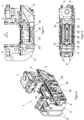
- the Figures 7 - 9 show a third embodiment of the clamping unit (1) for a blow molding machine with a blow molding tool, which is constructed with the clamping unit Figures 1 - 3 largely agrees. Matching components and assemblies of the third embodiment are included provided with the same reference numerals. There are differences from the first embodiment in that the first actuator (13) moves synchronously with the first mold carrier (4) and the second actuator (14) moves synchronously with the second mold carrier (5). In the representations Figures 7 - 9 The tool halves (2,3) are not shown in order to better show the components required for the synchronous movement.
- the locking unit (1) has a base frame which has side cheeks (9) arranged at a parallel distance from one another, on the upper edge of which a longitudinal guide (8) is arranged.
- the first and second mold carriers (4,5) and the drive (7) are connected to guide elements which are displaceably arranged on the longitudinal guides (8).
- first actuator (13) and the second actuator (14) are movably arranged on the closing unit (1) along additional stationary longitudinal guides (23).
- the stationary longitudinal guides (23) are arranged at a parallel distance from one another in the space between the side cheeks (9) and the frame elements (6) on a support structure (24) which is attached to the base frame of the locking unit (1) on the bottom side.
- the first coupling (19) transmits the movement of the first mold carrier (4) to the first actuator (13) and the second coupling (20) transmits the movement of the second mold carrier (5) to the second actuator (14).
- a first and a second guide carriage (25, 26) are provided, which are slidably guided on the additional longitudinal guides (23) arranged at a parallel distance are.
- the first actuator (13) extends vertically upwards from the first guide carriage (25) and the second actuator (14) extends vertically upwards from the second guide carriage (26).
- the first coupling (19) comprises an angle profile which is fastened on the one hand to the first mold carrier (4) and on the other hand to the first actuator (13).
- the second coupling (20) comprises an angle profile which is fastened on the one hand to the second mold carrier (5) and on the other hand to the second actuator (14).
- the actuators (13,14) arranged on the guide carriages (25,26) are moved synchronously.
- the first actuator (13) and the second actuator (14) can each be releasably connected to the underside of the associated lower mold part (2.2,3.2) via the switchable clutch (15, 16).
Landscapes
- Engineering & Computer Science (AREA)
- Manufacturing & Machinery (AREA)
- Mechanical Engineering (AREA)
- Moulds For Moulding Plastics Or The Like (AREA)
- Blow-Moulding Or Thermoforming Of Plastics Or The Like (AREA)
Description
- Die Offenbarung betrifft eine Schließeinheit für eine Blasformmaschine mit einem ersten und zweiten Formträger und ein an der Schließeinheit angeordnetes Blasformwerkzeug mit zwei Werkzeughälften, wobei jede Werkzeughälfte an einem der beiden Formträger lösbar befestigt ist und ein Form-oberteil und ein Formunterteil aufweist, die beiden Werkzeughälften zwischen einem Offenzustand und einen Schließzustand in einer ersten Bewegungsrichtung hin- und her bewegbar sind, das Formunterteil jeder Werkzeughälfte gegenüber dem Formoberteil jeder Werkzeughälfte in einer zur ersten Bewegungsrichtung verschiedenen zweiten Bewegungsrichtung zwischen einem Offenzustand und einem Schließzustand mittels mindestens eines ersten bzw. mindestens eines zweiten Aktuators hin und her bewegbar ist und das Blasformwerkzeug im Schließzustand der beiden Werkzeughälften ein Formnest mit Hinterschneidungen begrenzt, wenn sich die beiden Formunterteile ebenfalls im Schließzustand befinden.
- Die Offenbarung betrifft die Herstellung von Hohlkörpern im Wege des Blasformens, insbesondere die Herstellung von Behältern aus Kunststoff, wie beispielsweise Kanistern oder Flaschen. Bei der Her-stellung derartiger Hohlkörper im Wege des Blasformens erzeugt beispielsweise ein Extruder mit einem Blaskopf einen schlauchförmigen Vorformling, der von dem Blasformwerkzeug umschlossen und mit mittels eines Blasdorns eingebrachter Druckluft derart aufgeweitet wird, dass der betreffende Hohlkörper die Innenkontur des Blasformwerkzeugs erhält. Die beiden Werkzeughälften sind in der Regel in horizontaler Richtung mittels einer Schließeinheit gegeneinander verfahrbar, um das Blas-formwerkzeug zu öffnen oder zu schließen. Der Aufbau einer derartigen Schließeinheit wird beispielsweise in der
DE 102012 109 499 A1 offenbart. - In der Praxis können die herzustellenden Behälter an der Unter- und/oder Oberseite Vertiefungen aufweisen, beispielsweise zur Ausbildung eines gewölbten Behälterbodens oder eines Griffbereichs. Die Vertiefungen stellen gegenüber einem seitlichen Entformen der Behälter aus den Werkzeughälften eine Hinterschneidung dar. Aus diesem Grund sind aus dem Stand der Technik zweiteilige Werkzeughälften eines Blasformwerkzeugs bekannt, deren untere Bodenhälfte gegenüber einem Form-oberteil der Werkzeughälfte absenkbar ist. Zum Entformen des Behälters wird die untere Bodenhälfte jeder Werkzeughälfte separat über mindestens einen Hydraulikzylinder abgesenkt und anschließend für einen neuen Herstellungszyklus eines Behälters wieder angehoben.
- Bei einem ersten in der Praxis verwendeten Blasformwerkzeug sind jeweils zwei Hydraulikzylinder seitlich neben dem Formoberteil an einem Gestell der Werkzeughälfte befestigt und abtriebsseitig über die Kolbenstange mit der Bodenhälfte verbunden. Bei einem zweiten in der Praxis verwendeten Blasformwerkzeug ist lediglich ein Hydraulikzylinder an dem Gestell der Werkzeughälfte unterhalb der unteren Bodenhälfte befestigt und abtriebsseitig über die Kolbenstange mit der Unterseite der Bodenhälfte verbunden.
- Der Nachteil des ersten Blasformwerkzeugs besteht darin, dass zwei Aktuatoren je Werkzeughälfte erforderlich sind und die sich aus deren Anordnung ergebende Baubreite des Blasformwerkzeugs Probleme bereiten kann. Bei dem zweiten Blasformwerkzeug ist ein seitlicher Wechsel des Blasformwerkzeugs nicht möglich.
-
US 3,753,641 A offenbart eine Anlage zur Herstellung von Flaschen mit einer Mehrzahl von Blasformwerkzeugen, die in einer Rotationsbahn geführt sind. Jedes Blasformwerkzeug besteht aus einer äußeren Formhälfte und einer inneren Formhälfte. Die äußere Formhälfte ist auf einer kreisringförmigen Nockenbahn geführt und kann je nach Phasenlage auf der Nockenbahn an die innere Formhälfte in Radialrichtung herangeführt oder von der inneren Formhälfte in Radialrichtung entfernt werden. Jeweils an der äußeren Formhälfte und der inneren Formhälfte ist eine Mechanik mit einem doppelt aktuierten Zylinder und einem Getriebe angeordnet, die auf ein jeweils bewegliches Formendstück der äußere Formhälfte oder innen Formhälfte einwirken, um dieses zu bewegen. Die Formendstücke sind über Zapfenverbindungen fest mit der Mechanik verbunden. Die Mechanik weist für jedes Formendstück ein Paar von Schienen auf, die fest an der jeweiligen Formhälfte angeordnet sind. -
- Die
US 5,026,268 A offenbart eine Blasformanlage zum gleichzeitigen Blasformen von zwei Pflanz-kübeln, deren Randbereiche formgepresst werden. Jede Werkzeughälfte des Blasformwerkzeuges weist insgesamt fünf Formteile auf. Die jeweils beiden unteren und oberen Formteile jeder Werkzeughälfte sind starr miteinander verbunden und wiederum starr an einer Basis der jeweiligen Form-hälfte befestigt. Diese Basis ist Bestandteil des Blasformwerkzeuges und bildet das Gestell jeder der beiden Werkzeughälften. An diesem Gestell des Blasformwerkzeuges ist jeweils ein Hydraulikzylinder befestigt, der über eine Kolbenstange mit den beiden unteren Formteilen verbunden ist. Die fest miteinander verbundenen unteren Formteile jeder Werkzeughälfte sind zu einem dazwischen liegen-den Formteil relativ in Richtung einer die Formteile verbindenden Führungsstange beweglich. Das dazwischen liegende Formteil ist relativ zu den beiden fest mit der Basis jeder Formhälfte verbundenen oberen Formteilen in Richtung einer weiteren Führungsstange beweglich. Diese Relativbewegung erlaubt das Formpressen des Randbereichs der beiden Pflanzkübel. - Die Aktuatoren können maschinenseitig bauraumoptimiert in einem für das Blasformwerkzeug nicht oder nur eingeschränkt nutzbaren Raum positioniert werden. Vorzugsweise sind die Aktuatoren unterhalb der Formunterteile angeordnet und lösbar mit der Unterseite des jeweiligen Formunterteiles verbunden.
- Wenn der mindestens eine Aktuator unterhalb des Formunterteils angeordnet und lösbar mit der Unterseite des Formunterteils verbindbar ist, lässt sich das Blasformwerkzeug seitlich, das heißt quer zur Schließrichtung der beiden Werkzeughälften, aus der Schließeinheit entnehmen.
- Der mindestens eine erste Aktuator und der mindestens eine zweite Aktuator sind in der ersten Bewegungsrichtung gegeneinander beweglich an der Schließeinheit angeordnet.
- Um die Aktuatoren bereits während der Bewegung der Werkzeughälften in der ersten Bewegungsrichtung betätigen zu können, ist in einer bevorzugten Ausführung der Erfindung vorgesehen, dass sich der mindestens eine erste Aktuator synchron mit dem ersten Formträger bewegt und sich der mindestens eine zweite Aktuator synchron mit dem zweiten Formträger bewegt.
- Zur Synchronsierung der Bewegung kann in einer Ausgestaltung der Erfindung an dem ersten Formträger der mindestens eine erste Aktuator und an dem zweiten Formträger der mindestens eine zweite Aktuator unmittelbar angeordnet sein. An dem ersten Formträger kann eine Befestigungskonsole zur mittelbaren Befestigung des mindestens einen ersten Aktuators und an dem zweiten Formträger eine Befestigungskonsole zur mittelbaren Befestigung des mindestens einen zweiten Aktuators angeordnet sein.
- Um die Bewegung zu synchronisieren ist einer weiteren Ausführungsform der Erfindung vorgesehen, dass
- der mindestens eine erste Aktuator und der mindestens eine zweite Aktuator entlang mindestens einer ortsfesten Längsführung beweglich an der Schließeinheit angeordnet sind,
- eine erste Koppel die Bewegung des ersten Formträgers auf den mindestens einen ersten Aktuator und eine zweite Koppel die Bewegung des zweiten Formträgers auf den mindestens einen zweiten Aktuator überträgt.
- Als Koppel kommt beispielsweise eine Koppelstange oder ein Trägerelement in Betracht.
- Als ortsfeste Längsführung für die Aktuatoren kann eine an der Schließeinheit vorhandene ortsfeste Führung verwendet werden, entlang der auch der erste und der zweite Formträger verschieblich geführt sind. Alternativ ist eine separate ortsfeste Längsführung für die Aktuatoren vorgesehen.
- Mittels der lösbaren Verbindung zwischen Aktuator und Formunterteil wird eine definierte Schnittstelle für die Kraftübertragung geschaffen. Um die Verbindung zwischen Aktuator und Formunterteil schnell lösen und wieder herstellen zu können, ist die lösbare Verbindung in einer vorteilhaften Ausgestaltung der Erfindung als Kupplung ausgeführt, die für die Übertragung von Kräften zwischen dem Aktuator und dem Formunterteil zumindest in der zweiten Bewegungsrichtung, das heißt senkrecht zu der horizontalen Schließ- und Öffnungsbewegung der beiden Werkzeughälften eingerichtet ist.
- Im Interesse einer Automatisierung des Kupplungsvorgangs ist die Kupplung vorzugsweise als schaltbare, kraft- oder formschlüssige Kupplung ausgeführt, beispielsweise als elektromagnetische Kupplung.
- Die Aktuatoren sind derart eingerichet, dass sie das Formunterteil in der zweiten Bewegungsrichtung linear zwischen dem Offenzustand und dem Schließzustand hin- und herbwegen können. Die Aktuatoren können als Linearantriebe ausgeführt sein, insbesondere als fluidbetriebene Arbeitszylinder. Alternativ ist der Aktuator ein Schubkurbelgetriebe, das eine Drehbewegung in
eine oszillierende Schubbewegung in der zweiten Bewegungsrichtung umformt. - Die zweite Bewegungsrichtung der Formunterteile ist üblicherweise senkrecht zu der ersten Bewegungsrichtung zum Öffnen und Schließen des Blasformwerkzeugs, kann jedoch abhängig von dem herzustellenden Hohlkörper auch unter einem anderen Winkel verlaufen.
- Nachfolgend wird die Erfindung anhand der Figuren näher erläutert. Es zeigen
- Figur 1
- eine Seiteneinsicht einer ersten Ausführungsform einer Schließeinheit für eine Blasformmaschine,
- Figur 2
- einen Längsschnitt durch die Schließeinheit nach
Figur 1 , - Figur 3
- eine perspektivische Ansicht der Schließeinheit nach
Figur 1 , - Figur 4
- eine Seiteneinsicht einer zweiten Ausführungsform einer Schließeinheit für eine Blasformmaschine,
- Figur 5
- eine Draufsicht auf die Schließeinheit nach
Figur 4 , - Figur 6
- eine perspektivische Ansicht der Schließeinheit nach
Figur 4 , - Figur 7
- eine Seiteneinsicht, teilweise weggebrochen, einer zweiten Ausführungsform einer Schließeinheit für eine Blasformmaschine,
- Figur 8
- eine Draufsicht auf die Schließeinheit nach
Figur 7 sowie - Figur 9
- eine perspektivische Ansicht der Schließeinheit nach
Figur 7 . - Hinsichtlich des Aufbaus der Schließeinheit (1) der vorliegenden Erfindung, insbesondere des gemeinsamen Antriebs zum Hin- und Herbewegen der Formträger, des Grundrahmens mit daran angeordneten Führungen, der U-förmigen Rahmenelemente sowie der Gleichlaufeinrichtung wird ergänzend auf die
DE 10 2012 109 499 A1 Bezug genommen. - Die
Figuren 1 - 3 zeigen eine erste Ausführungsform der Schließeinheit 1 für eine Blasformmaschine mit einem Blasformwerkzeug mit zwei Werkzeughälften (2,3), wobei jede Werkzeughälfte (2,3) ein Formoberteil (2.1, 3.1) und ein Formunterteil (2.2, 3.2) aufweist. Die Werkzeughälfte (2) ist an einem ersten Formträger (4) und die Werkzeughälfte (3) an einem zweiten Formträger (5) lösbar befestigt. Der erste Formträger (4) ist gelenkig mit den beiden Rahmenelementen (6) der Schließeinheit (1) verbunden. Der zweite Formträger (5) ist mit einem Antrieb (7) zum Hin- und Herbewegen der beiden Formträger (4,5) und damit der Werkzeughälften (2,3) verbunden, wobei sich der Antrieb (7) ebenfalls an den Rahmenelementen (6) abstützt. - Die Schließeinheit (1) weist einen Grundrahmen auf, der im parallelen Abstand zueinander angeordnete Seitenwangen (9) aufweist, an deren obere Kante jeweils eine Längsführung (8) angeordnet ist. Der erste und zweite Formträger (4,5) und der Antrieb (7) sind mit Führungselementen verbunden, die auf den Längsführungen (8) verschieblich angeordnet sind. An dem Grundrahmen der Schließeinheit (1) ist zudem eine Gleichlaufeinrichtung (10) angeordnet, durch welche die Schließ- und Öffnungsbewegung der beiden Werkzeughälften (2,3) in einer ersten Bewegungsrichtung (17) symmetrisch erfolgt.
- Die
Figuren 1 - 3 zeigen die beiden Werkzeughälften (2,3) in einem Offenzustand. Die Formunterteile (2.2, 3.2) befinden sich ebenfalls in einem Offenzustand. Im Schließzustand liegen die beiden Werkzeughälften (2,3) sowie die jeweiligen Formober- und Unterteile (2.1, 2.2 bzw. 3.1, 3.2) aneinander an und begrenzen ein Formnest zur Herstellung eines Hohlkörpers, insbesondere eines Kanisters. - An dem ersten Formträger (4) und an dem zweiten Formträger (5) ist jeweils an der Unterseite eine Befestigungskonsole (11,12) befestigt. An jeder Befestigungskonsole (11,12) ist unterhalb des Formunterteils (2.2, 3.2) jeweils ein erster Aktuator (13) bzw. ein zweiter Aktuator (14) befestigt. Über eine schaltbare Kupplung (15,16) ist der erste Aktuator (13) und der zweite Aktuator (14) jeweils mit der Unterseite des zugeordneten Formunterteils (2.2, 3.2) lösbar verbindbar.
- Mittels des beispielsweise als Linearantrieb ausgeführten Aktuators (13,14) lassen sich die Formunterteile (2.2,3.2) gegenüber den Formoberteilen (2.1,3.1) der beiden Werkzeughälften (2,3) in einer zweiten Bewegungsrichtung (18) in senkrechter Richtung bewegen, um das Formunterteil (2.2, 3.2) jeder Werkzeughälfte (2,3) gegenüber dem Formoberteil (2.1) der jeweiligen Werkzeughälfte (2,3)zwischen einem Offenzustand und einem Schließzustand hin- und herzubewegen. Die zweite Bewegungsrichtung (18) verläuft senkrecht zu der ersten Bewegungsrichtung (17).
- Aus
Figur 2 ist erkennbar, dass sowohl die beiden Formoberteile (2.1,3.1) und die beiden Formunterteile (2.2,3.2) Formbereiche aufweisen, die zur Ausbildung von Vertiefungen an der Unter- und Oberseite des herzustellenden Hohlkörpers ausgebildet sind. Diese Formbereiche erfordern es, dass die Formunterteile (2.2,3.2) vor dem Entformen des Hohlkörperes in einem Offenzustand mittels der Aktuatoren (13,14) gebracht werden. - Aufgrund der Anordnung der Aktuatoren (13,14) in dem Zwischenraum zwischen den Rahmenelementen (6) wird der Formaufspannbereich nicht beeinträchtigt. Des Weiteren begünstigen die an der Unterseite der Formunterteile (2.2,3.2) angreifenden Kupplungen (15,16) den Wechsel des Blasformwerkszeugs. Schließlich zeigen die Figuren, dass der Produktionsfreiraum für die Hohlkörper nicht durch die Aktuatoren (13,14) eingeschränkt wird.
- Die
Figuren 4 - 6 zeigen eine zweite Ausführungsform der Schließeinheit (1) für eine Blasformmaschine mit einem Blasformwerkzeug, die im Aufbau mit der Schließeinheit (1) nach denFiguren 1 - 3 weitgehend übereinstimmt. Übereinstimmende Bauteile und Baugruppen der zweiten Ausführungsform sind mit gleichen Bezugszeichen versehen. Unterschiede zu der ersten Ausführungsform bestehen insoweit, wie sich der erste Aktuator (13) synchron mit dem ersten Formträger (4) und der zweite Aktuator (14) synchron mit dem zweiten Formträger (5) bewegt. In den Darstellungen nachFiguren 4 - 6 wurden die Werkzeughälften (2,3) nicht dargestellt, um die für die synchrone Bewegung erforderlichen Bauteile besser darstellen zu können. - Das Schließeinheit (1) weist wie bei der ersten Ausführungsform einen Grundrahmen auf, der im parallelen Abstand zueinander angeordnete Seitenwangen (9) aufweist, an deren obere Kante jeweils eine Längsführung (8) angeordnet ist. Der erste und zweite Formträger (4,5) und der Antrieb (7) sind mit Führungselementen verbunden, die auf den Längsführungen (8) verschieblich angeordnet sind.
- Um die Bewegung zu synchronisieren ist vorgesehen, dass der erste Aktuator (13) und der zweite Aktuator (14) ebenfalls entlang der ohnehin vorhandenen ortsfesten Längsführungen (8) beweglich an der Schließeinheit (1) angeordnet sind und eine erste Koppel (19) die Bewegung des ersten Formträgers (4) auf den ersten Aktuator (13) und eine zweite Koppel (20) die Bewegung des zweiten Formträgers (5) auf den zweiten Aktuator (14) überträgt.
- Um den ersten und zweiten Aktuator (13,14) entlang der Längsführungen (8) zu bewegen, sind eine erste und eine zweite Konsole (21,22) vorgesehen. Jede der beiden Konsolen (21,22) ist an den äußeren Rändern mit Führungselementen versehen, die auf den im parallelen Abstand angeordneten Längsführungen (8) verschieblich angeordnet sind. An der ersten Konsole (21) ist mittig der erste Aktuator (13) und an der zweiten Konsole mittig der zweite Aktuator (14) befestigt. Die erste Koppel (19) umfasst zwei Profilstücke, die einerseits an dem ersten Formträger (4) und andererseits an den äußeren Rändern der ersten Konsole (21) befestigt sind. Die zweite Koppel (20) umfasst ebenfalls zwei Profilstücke, die einerseits an dem zweiten Formträger (5) und andererseits an den äußeren Rändern der zweiten Konsole (22) befestigt sind.
- Bewegen sich nun die Formträger (4,5) in der ersten Bewegungsrichtung (17) werden die erste und zweite Konsole (21,22) synchron mit bewegt, sodass sich die an den Konsolen (21,22) befestigten Aktuatoren (13,14) stets unterhalb der Formunterteile (2.2, 3.2) befinden.
- Über die schaltbare Kupplung (15,16) ist der erste Aktuator (13) und der zweite Aktuator (14) jeweils mit der Unterseite des zugeordneten Formunterteils (2.2,3.2) lösbar verbindbar.
- Die
Figuren 7 - 9 zeigen eine dritte Ausführungsform der Schließeinheit (1) für eine Blasformmaschine mit einem Blasformwerkzeug, die im Aufbau mit der Schließeinheit nachFiguren 1 - 3 weitgehend übereinstimmt. Übereinstimmende Bauteile und Baugruppen der dritten Ausführungsform sind mit gleichen Bezugszeichen versehen. Unterschiede zu der ersten Ausführungsform bestehen insoweit, wie sich der erste Aktuator (13) synchron mit dem ersten Formträger (4) und der zweite Aktuator (14) synchron mit dem zweiten Formträger (5) bewegt. In den Darstellungen nachFiguren 7 - 9 wurden die Werkzeughälften (2,3) nicht dargestellt, um die für die synchrone Bewegung erforderlichen Bauteile besser darstellen zu können. - Das Schließeinheit (1) weist wie bei der ersten Ausführungsform einen Grundrahmen auf, der im parallelen Abstand zueinander angeordnete Seitenwangen (9) aufweist, an deren obere Kante jeweils eine Längsführung (8) angeordnet ist. Der erste und zweite Formträger (4,5) und der Antrieb (7) sind mit Führungselementen verbunden, die auf den Längsführungen (8) verschieblich angeordnet sind.
- Um die Bewegung zu synchronisieren ist vorgesehen, dass der erste Aktuator (13) und der zweite Aktuator (14) entlang zusätzlicher ortsfester Längsführungen (23) beweglich an der Schließeinheit (1) angeordnet sind. Die ortsfesten Längsführungen (23) sind im parallelen Abstand zueinander in dem Zwischenraum zwischen den Seitenwangen (9) und den Rahmenelementen (6) auf einer Tragkonstruktion (24) angeordnet, die an dem Grundrahmen der Schließeinheit (1) bodenseitig befestigt ist.
- Die erste Koppel (19) überträgt die Bewegung des ersten Formträgers (4) auf den ersten Aktuator (13) und die zweite Koppel (20) die Bewegung des zweiten Formträgers (5) auf den zweiten Aktuator (14).
- Um den ersten und zweiten Aktuator (13,14) entlang der zusätzlichen Längsführungen (23) zu bewegen, sind eine erster und eine zweiter Führungswagen (25,26) vorgesehen, die auf den im parallelen Abstand angeordneten, zusätzlichen Längsführungen (23) verschieblich geführt sind. Von dem ersten Führungswagen (25) erstreckt sich in senkrechter Richtung nach oben der erste Aktuator (13) und von dem zweiten Führungswagen (26) erstreckt sich in senkrechter Richtung nach oben der zweite Aktuator (14). Die erste Koppel (19) umfasst ein Winkelprofil, das einerseits an dem ersten Formträger (4) und andererseits an dem ersten Aktuator (13) befestigt ist. Die zweite Koppel (20) umfasst ein Winkelprofil, das einerseits an dem zweiten Formträger (5) und andererseits an dem zweiten Aktuator (14) befestigt ist.
- Bewegen sich die Formträger (4,5) in der ersten Bewegungsrichtung (17) werden die an den Führungswagen (25,26) angeordneten Aktuatoren (13,14) synchron mit bewegt.
- Über die schaltbare Kupplung (15,16) ist der erste Aktuator (13) und der zweite Aktuator (14) jeweils mit der Unterseite des zugeordneten Formunterteils (2.2,3.2) lösbar verbindbar.
-
- 1
- Schließeinheit
- 2
- Werkzeughälfte
- 2.1
- Formoberteil
- 2.2
- Formunterteil
- 3
- Werkzeughälfte
- 3.1
- Formoberteil
- 3.2
- Formunterteil
- 4
- Erster Formträger
- 5
- Zweiter Formträger
- 6
- Rahmenelemente
- 7
- Antrieb
- 8
- Längsführung
- 9
- Seitenwangen
- 10
- Gleichlaufeinrichtung
- 11
- Befestigungskonsole
- 12
- Befestigungskonsole
- 13
- Erster Aktuator
- 14
- Zweiter Aktuator
- 15
- Kupplung
- 16
- Kupplung
- 17
- Erste Bewegungsrichtung
- 18
- Zweite Bewegungsrichtung
- 19
- Erste Koppel
- 20
- Zweite Koppel
- 21
- Erste Konsole
- 22
- Zweite Konsole
- 23
- Zusätzliche Längsführung
- 24
- Tragkonstruktion
- 25
- Erster Führungswagen
- 26
- Zweiter Führungswagen
Claims (12)
- Schließeinheit für eine Blasformmaschine, wobei in der Blasformmaschine mindestens ein Blasformwerkzeug mit zweiteiligen Werkzeughälften (2, 3) verwendbar ist, das im Schließzustand der beiden Werkzeughälften (2, 3) ein Formnest mit Hinterschneidungen begrenzt, und wobei die Schließeinheit (1) einen ersten und einen zweiten Formträger (4, 5) umfasst, an denen das Blasformwerkzeug anordenbar und lösbar befestigbar ist, und wobei jeweils ein Formunterteil (2.2, 3.3) der Werkzeughälfte, d.h. die untere Bodenhälfte, gegenüber einem Formoberteil (2.1, 3.1) der Werkzeughälfte absenkbar ist, und wobei die beiden Werkzeughälften (2, 3) zwischen einem Offenzustand und einem Schließzustand in einer ersten Bewegungsrichtung (17) hin und her bewegbar sind, und wobei die Schließeinheit (1) mindestens einen ersten Aktuator (13) und mindestens einen zweiten Aktuator (14) umfasst, und wobei das Formunterteil (2.2, 3.2) jeder Werkzeughälfte gegenüber dem Formoberteil (2.1, 3.1) mittels des mindestens einen ersten Aktuators (13) oder mittels des mindestens einen zweiten Aktuators (14) zwischen einem Offenzustand und einem Schließzustand in einer zweiten Bewegungsrichtung (18) hin und her bewegbar ist, die von der ersten Bewegungsrichtung (17) verschieden ist, dadurch gekennzeichnet, dass- die Aktuatoren (13, 14) an der Schließeinheit (1) angeordnet sind und bei einem Wechsel des Blasformwerkzeugs an der Schließeinheit (1) verbleiben, und wobei- eines der beiden Formunterteile (2.2, 3.2) lösbar mit dem Abtrieb des mindestens einen ersten Aktuators (13) und das andere der beiden Formunterteile (2.2, 3.2) lösbar mit einem Abtrieb des mindestens einen zweiten Aktuators (14) verbindbar ist, sodass der Wechsel des Blasformwerkzeugs vereinfacht ist, und wobei- der mindestens eine erste Aktuator (13) und der mindestens eine zweite Aktuator (14) in der ersten Bewegungsrichtung (17) gegeneinander beweglich an der Schließeinheit (1) angeordnet sind.
- Schließeinheit nach Anspruch 1, wobei eine ortsfeste Längsführung (8, 23) für die Aktuatoren vorgesehen ist.
- Schließeinheit nach Anspruch 1 oder 2, wobei die Aktuatoren entlang einer ortsfesten Längsführung (8, 23) beweglich an der Schließeinheit angeordnet sind und eine erste Koppel (19) die Bewegung eines ersten Formträgers (4) der Schließeinheit (1) auf den mindestens einen ersten Aktuator (13) überträgt und eine zweite Koppel (20) die Bewegung eines zweiten Formträgers (5) der Schließeinheit (1) auf den mindestens einen zweiten Aktuator (14) überträgt.
- Schließeinheit nach einem der vorhergehenden Ansprüche 2 oder 3, wobei entlang der ortsfesten Führung der erste Formträger (4) und der zweite Formträger (5) verschieblich geführt sind, und wobei- diese ortsfeste Führung als die ortsfeste Längsführung (8) für die Aktuatoren (13, 14) verwendet wird, ODER- eine separate ortsfeste Längsführung (23) für die Aktuatoren (13, 14) vorgesehen ist.
- Schließeinheit nach einem der vorhergehenden Ansprüche, wobei die Aktuatoren (13, 14) derart eingerichtet sind, dass sie das Formunterteil (2.2, 3.2) in der zweiten Bewegungsrichtung (18) linear zwischen dem Offenzustand und dem Schließzustand hin und her bewegen, wobei insbesondere- die Aktuatoren (13, 14) als fluidbetriebene Arbeitszylinder ausgebildet sind, ODER- jeder Aktuator (13, 14) ein Schubkurbelgetriebe ist, das eine Drehbewegung in eine oszillierende Schubbewegung in der zweiten Bewegungsrichtung (18) umformt.
- Schließeinheit nach einem der vorhergehenden Ansprüche, wobei die Aktuatoren (13, 14) unterhalb der Formunterteile (2.2, 3.2) angeordnet sind.
- Schließeinheit nach einem der vorhergehenden Ansprüche, wobei mittels der lösbaren Verbindung zwischen Aktuator (13, 14) und Formunterteil (2.2, 3.2) eine definierte Schnittstelle für die Kraftübertragung geschaffen ist, um die Verbindung zwischen Aktuator und Formunterteil schnell lösen und wieder herstellen zu können.
- Schließeinheit nach einem der vorhergehenden Ansprüche, wobei die Kupplung (15, 16) als schaltbare, kraft- oder formschlüssige Kupplung ausgeführt ist, insbesondere als elektromagnetische Kupplung.
- Schließeinheit nach Anspruch 1 oder 2, wobei sich der mindestens eine erste Aktuator (13) synchron mit einem ersten Formträger (4) der Schließeinheit (1) bewegt und sich der mindestens eine zweite Aktuator (14) synchron mit einem zweiten Formträger (5) der Schließeinheit (1) bewegt.
- Schließeinheit nach einem der vorhergehenden Ansprüche, wobei- an dem ersten Formträger (4) der mindestens eine erste Aktuator (13) unmittelbar angeordnet ist und an dem zweiten Formträger (5) der mindestens eine zweite Aktuator (14) unmittelbar angeordnet ist, ODER wobei- an dem ersten Formträger (4) eine Befestigungskonsole (11) zur mittelbaren Befestigung des mindestens einen ersten Aktuators (13) angeordnet ist und an dem zweiten Formträger (5) eine Befestigungskonsole (12) zur mittelbaren Befestigung des mindestens einen zweiten Aktuators (14) angeordnet ist.
- Schließeinheit nach dem vorhergehenden Anspruch, wobei die Befestigungskonsolen (11,12) jeweils an der Unterseite an dem ersten Formträger (4) und an dem zweiten Formträger (5) befestigt sind, und wobei an jeder Befestigungskonsole (11, 12) jeweils unterhalb des Formunterteils ein erster Aktuator (13) bzw. ein zweiter Aktuator (14) befestigt ist.
- Blasformmaschine mit einer Schließeinheit (1) gemäß einem der vorhergehenden Ansprüche.
Applications Claiming Priority (2)
| Application Number | Priority Date | Filing Date | Title |
|---|---|---|---|
| DE102019126397.2A DE102019126397B4 (de) | 2019-09-30 | 2019-09-30 | Satz von Aktuatoren für eine Schließeinheit, Schließeinheit für eine Blasformmaschine sowie Blasformmaschine mit einer Schließeinheit |
| PCT/EP2020/077060 WO2021063867A1 (de) | 2019-09-30 | 2020-09-28 | Schliesseinheit und blasformwerkzeug für eine blasformmaschine |
Publications (3)
| Publication Number | Publication Date |
|---|---|
| EP4003692A1 EP4003692A1 (de) | 2022-06-01 |
| EP4003692C0 EP4003692C0 (de) | 2023-09-20 |
| EP4003692B1 true EP4003692B1 (de) | 2023-09-20 |
Family
ID=72801458
Family Applications (1)
| Application Number | Title | Priority Date | Filing Date |
|---|---|---|---|
| EP20788723.3A Active EP4003692B1 (de) | 2019-09-30 | 2020-09-28 | Schliesseinheit für eine blasformmaschine |
Country Status (4)
| Country | Link |
|---|---|
| US (1) | US20220371255A1 (de) |
| EP (1) | EP4003692B1 (de) |
| DE (1) | DE102019126397B4 (de) |
| WO (1) | WO2021063867A1 (de) |
Families Citing this family (1)
| Publication number | Priority date | Publication date | Assignee | Title |
|---|---|---|---|---|
| EP4201636A4 (de) * | 2020-08-20 | 2024-09-04 | Nissei ASB Machine Co., Ltd. | Blasformvorrichtung |
Family Cites Families (16)
| Publication number | Priority date | Publication date | Assignee | Title |
|---|---|---|---|---|
| US3499071A (en) * | 1967-06-19 | 1970-03-03 | Procter & Gamble | Apparatus for in-mold removal of flash |
| US3753641A (en) * | 1969-12-22 | 1973-08-21 | Continental Can Co | Mold for articles having undercut portions |
| US3806300A (en) * | 1971-05-27 | 1974-04-23 | Ethyl Dev Corp | Apparatus for forming the neck on a plastic container |
| US3910742A (en) * | 1972-01-14 | 1975-10-07 | Ethyl Dev Corp | Apparatus for removing waste material from a plastic article |
| DE3613543C1 (de) * | 1986-04-22 | 1986-12-18 | Fried. Krupp Gmbh, 4300 Essen | Schnellspanneinheit für eine Blasform |
| US5026268A (en) * | 1990-03-30 | 1991-06-25 | Zarn, Inc. | Apparatus for blow molding an article with compression molded areas |
| US5227114A (en) * | 1992-07-16 | 1993-07-13 | The Lerio Corporation | Process for manufacturing containers with thickened flanges |
| JPH0825469A (ja) * | 1994-07-19 | 1996-01-30 | Tahara:Kk | 中空成形機の金型構造 |
| ATE345207T1 (de) * | 2004-07-01 | 2006-12-15 | Kautex Maschinenbau Gmbh | Verfahren zur herstellung von hohlkörpern aus thermoplastischem kunststoff sowie vorrichtung zur durchführung des verfahrens |
| US7754138B1 (en) * | 2006-07-10 | 2010-07-13 | Akira Kashiwase | Apparatus and method of manufacturing stackable containers |
| DE102009030492B4 (de) * | 2009-06-24 | 2023-06-15 | Kautex Maschinenbau Gmbh | Verfahren zur Herstellung eines Kunststoffartikels sowie Blasformwerkzeug |
| US8377368B2 (en) * | 2009-12-11 | 2013-02-19 | Ti Automotive Technology Center Gmbh | Component mounting arrangement |
| DE102010025937A1 (de) * | 2010-07-02 | 2012-01-05 | Kautex Maschinenbau Gmbh | Verfahren zur Herstellung eines Kunststoffartikels sowie Blasformwerkzeug zur Durchführung des Verfahrens |
| DE102012109499A1 (de) * | 2012-10-05 | 2014-04-10 | Kautex Maschinenbau Gmbh | Schließgestell für eine Blasformmaschine und Blasformmaschine |
| FR3011763B1 (fr) * | 2013-10-14 | 2015-12-11 | Sidel Participations | "unite de moulage pour la fabrication de recipients comportant une pince de compensation" |
| DE102019110917A1 (de) * | 2019-04-26 | 2020-10-29 | Kautex Maschinenbau Gmbh | Hydrostatisches Linear-Antriebssystem |
-
2019
- 2019-09-30 DE DE102019126397.2A patent/DE102019126397B4/de active Active
-
2020
- 2020-09-28 WO PCT/EP2020/077060 patent/WO2021063867A1/de not_active Ceased
- 2020-09-28 US US17/764,885 patent/US20220371255A1/en not_active Abandoned
- 2020-09-28 EP EP20788723.3A patent/EP4003692B1/de active Active
Also Published As
| Publication number | Publication date |
|---|---|
| DE102019126397A1 (de) | 2021-04-01 |
| US20220371255A1 (en) | 2022-11-24 |
| DE102019126397B4 (de) | 2023-05-25 |
| EP4003692A1 (de) | 2022-06-01 |
| WO2021063867A1 (de) | 2021-04-08 |
| EP4003692C0 (de) | 2023-09-20 |
Similar Documents
| Publication | Publication Date | Title |
|---|---|---|
| AT409243B (de) | Blasformmaschine | |
| EP2311625B1 (de) | Formträger mit Antriebseinrichtung | |
| EP1044784B1 (de) | Spannvorrichtung und -verfahren für Blasformen | |
| EP4003692B1 (de) | Schliesseinheit für eine blasformmaschine | |
| DE2429223A1 (de) | Kontinuierlich arbeitende rotationsvorrichtung zum formblasen von kunststoffhohlkoerpern | |
| EP1060865A2 (de) | Verfahren und Vorrichtung zum Schliessen und Öffnen der Formwerkzeuge einer Kunststoffverarbeitungsmaschine | |
| DE2911143A1 (de) | Verfahren und vorrichtung zur herstellung von hohlkoerpern, insbesondere kunststoff-flaschen | |
| WO2017059930A1 (de) | Blasformmaschine mit automatisch betätigbarer bodenankopplung und verfahren zum betreiben deren vorrichtung | |
| DE4438143A1 (de) | Verfahren und Vorrichtung zum Herstellen von geschäumten Kunststoffteilen | |
| DE19922684C2 (de) | Blasformmaschine für das abfallarme Blasen | |
| DE2423503C3 (de) | Vorrichtung zum Herstellen von Hohlkörpern aus thermoplastischem Kunststoff | |
| DE3925859C2 (de) | Blasformmaschine | |
| DE102009051934B3 (de) | Schließeinheit für eine Spritzgießmaschine | |
| DE102009007151B4 (de) | Entgratpresse mit einer Vorrichtung zur Entnahme eines entgrateten Werkstücks, Entnahmevorrichtung für diese Entgratpresse sowie Verfahren zur Entnahme eines entgrateten Werkstücks aus dieser Entgratpresse | |
| EP2614948A1 (de) | Blasformsystem sowie Verfahren zur Blasformung von Hohlkörpern | |
| DE1920920C3 (de) | GieBerei-Maschine zum Herstellen von Kernen oder Formmasken aus Formsand | |
| EP1614524B1 (de) | Hohlkörperblasanlage | |
| DE10307669B3 (de) | Druckgußmaschine | |
| EP2498972B1 (de) | Blasformwerkzeug | |
| DE10224708C1 (de) | Zusammenfallbarer Kern für Spritzwerkzeuge | |
| EP0734837A1 (de) | Vorrichtung zum Transportieren eines Vorformlings von dem Schlauchkopf zu der Blasform einer Blasmaschine | |
| DE102005036429B4 (de) | Vorrichtung zur Innenhochdruck-Umformung von metallischen, hohlkörperförmigen Rohlingen | |
| DE102004013825A1 (de) | Gelenkarmtransportvorrichtung | |
| DE9308467U1 (de) | Blasformmaschine | |
| DE1479449B1 (de) | Vorrichtung zum herstellen von hohlkoerpern aus thermo plastischen kunststoffen im blasverfahren |
Legal Events
| Date | Code | Title | Description |
|---|---|---|---|
| STAA | Information on the status of an ep patent application or granted ep patent |
Free format text: STATUS: UNKNOWN |
|
| STAA | Information on the status of an ep patent application or granted ep patent |
Free format text: STATUS: THE INTERNATIONAL PUBLICATION HAS BEEN MADE |
|
| PUAI | Public reference made under article 153(3) epc to a published international application that has entered the european phase |
Free format text: ORIGINAL CODE: 0009012 |
|
| STAA | Information on the status of an ep patent application or granted ep patent |
Free format text: STATUS: REQUEST FOR EXAMINATION WAS MADE |
|
| 17P | Request for examination filed |
Effective date: 20220222 |
|
| AK | Designated contracting states |
Kind code of ref document: A1 Designated state(s): AL AT BE BG CH CY CZ DE DK EE ES FI FR GB GR HR HU IE IS IT LI LT LU LV MC MK MT NL NO PL PT RO RS SE SI SK SM TR |
|
| STAA | Information on the status of an ep patent application or granted ep patent |
Free format text: STATUS: EXAMINATION IS IN PROGRESS |
|
| 17Q | First examination report despatched |
Effective date: 20220629 |
|
| DAV | Request for validation of the european patent (deleted) | ||
| DAX | Request for extension of the european patent (deleted) | ||
| RIC1 | Information provided on ipc code assigned before grant |
Ipc: B29C 49/04 20060101ALN20230308BHEP Ipc: B29L 31/00 20060101ALI20230308BHEP Ipc: B29C 49/48 20060101ALI20230308BHEP Ipc: B29C 49/56 20060101ALI20230308BHEP Ipc: B29C 49/54 20060101AFI20230308BHEP |
|
| GRAP | Despatch of communication of intention to grant a patent |
Free format text: ORIGINAL CODE: EPIDOSNIGR1 |
|
| STAA | Information on the status of an ep patent application or granted ep patent |
Free format text: STATUS: GRANT OF PATENT IS INTENDED |
|
| INTG | Intention to grant announced |
Effective date: 20230418 |
|
| GRAS | Grant fee paid |
Free format text: ORIGINAL CODE: EPIDOSNIGR3 |
|
| GRAA | (expected) grant |
Free format text: ORIGINAL CODE: 0009210 |
|
| STAA | Information on the status of an ep patent application or granted ep patent |
Free format text: STATUS: THE PATENT HAS BEEN GRANTED |
|
| AK | Designated contracting states |
Kind code of ref document: B1 Designated state(s): AL AT BE BG CH CY CZ DE DK EE ES FI FR GB GR HR HU IE IS IT LI LT LU LV MC MK MT NL NO PL PT RO RS SE SI SK SM TR |
|
| REG | Reference to a national code |
Ref country code: GB Ref legal event code: FG4D Free format text: NOT ENGLISH |
|
| REG | Reference to a national code |
Ref country code: CH Ref legal event code: EP |
|
| REG | Reference to a national code |
Ref country code: IE Ref legal event code: FG4D Free format text: LANGUAGE OF EP DOCUMENT: GERMAN |
|
| REG | Reference to a national code |
Ref country code: DE Ref legal event code: R096 Ref document number: 502020005333 Country of ref document: DE |
|
| U01 | Request for unitary effect filed |
Effective date: 20231020 |
|
| U07 | Unitary effect registered |
Designated state(s): AT BE BG DE DK EE FI FR IT LT LU LV MT NL PT SE SI Effective date: 20231026 |
|
| PG25 | Lapsed in a contracting state [announced via postgrant information from national office to epo] |
Ref country code: GR Free format text: LAPSE BECAUSE OF FAILURE TO SUBMIT A TRANSLATION OF THE DESCRIPTION OR TO PAY THE FEE WITHIN THE PRESCRIBED TIME-LIMIT Effective date: 20231221 |
|
| PG25 | Lapsed in a contracting state [announced via postgrant information from national office to epo] |
Ref country code: RS Free format text: LAPSE BECAUSE OF FAILURE TO SUBMIT A TRANSLATION OF THE DESCRIPTION OR TO PAY THE FEE WITHIN THE PRESCRIBED TIME-LIMIT Effective date: 20230920 Ref country code: NO Free format text: LAPSE BECAUSE OF FAILURE TO SUBMIT A TRANSLATION OF THE DESCRIPTION OR TO PAY THE FEE WITHIN THE PRESCRIBED TIME-LIMIT Effective date: 20231220 Ref country code: HR Free format text: LAPSE BECAUSE OF FAILURE TO SUBMIT A TRANSLATION OF THE DESCRIPTION OR TO PAY THE FEE WITHIN THE PRESCRIBED TIME-LIMIT Effective date: 20230920 Ref country code: GR Free format text: LAPSE BECAUSE OF FAILURE TO SUBMIT A TRANSLATION OF THE DESCRIPTION OR TO PAY THE FEE WITHIN THE PRESCRIBED TIME-LIMIT Effective date: 20231221 |
|
| PG25 | Lapsed in a contracting state [announced via postgrant information from national office to epo] |
Ref country code: IS Free format text: LAPSE BECAUSE OF FAILURE TO SUBMIT A TRANSLATION OF THE DESCRIPTION OR TO PAY THE FEE WITHIN THE PRESCRIBED TIME-LIMIT Effective date: 20240120 |
|
| PG25 | Lapsed in a contracting state [announced via postgrant information from national office to epo] |
Ref country code: ES Free format text: LAPSE BECAUSE OF FAILURE TO SUBMIT A TRANSLATION OF THE DESCRIPTION OR TO PAY THE FEE WITHIN THE PRESCRIBED TIME-LIMIT Effective date: 20230920 |
|
| PG25 | Lapsed in a contracting state [announced via postgrant information from national office to epo] |
Ref country code: SM Free format text: LAPSE BECAUSE OF FAILURE TO SUBMIT A TRANSLATION OF THE DESCRIPTION OR TO PAY THE FEE WITHIN THE PRESCRIBED TIME-LIMIT Effective date: 20230920 Ref country code: RO Free format text: LAPSE BECAUSE OF FAILURE TO SUBMIT A TRANSLATION OF THE DESCRIPTION OR TO PAY THE FEE WITHIN THE PRESCRIBED TIME-LIMIT Effective date: 20230920 Ref country code: IS Free format text: LAPSE BECAUSE OF FAILURE TO SUBMIT A TRANSLATION OF THE DESCRIPTION OR TO PAY THE FEE WITHIN THE PRESCRIBED TIME-LIMIT Effective date: 20240120 Ref country code: ES Free format text: LAPSE BECAUSE OF FAILURE TO SUBMIT A TRANSLATION OF THE DESCRIPTION OR TO PAY THE FEE WITHIN THE PRESCRIBED TIME-LIMIT Effective date: 20230920 Ref country code: CZ Free format text: LAPSE BECAUSE OF FAILURE TO SUBMIT A TRANSLATION OF THE DESCRIPTION OR TO PAY THE FEE WITHIN THE PRESCRIBED TIME-LIMIT Effective date: 20230920 Ref country code: SK Free format text: LAPSE BECAUSE OF FAILURE TO SUBMIT A TRANSLATION OF THE DESCRIPTION OR TO PAY THE FEE WITHIN THE PRESCRIBED TIME-LIMIT Effective date: 20230920 |
|
| REG | Reference to a national code |
Ref country code: CH Ref legal event code: PL |
|
| U21 | Renewal fee for the european patent with unitary effect paid with additional fee |
Year of fee payment: 4 Effective date: 20240325 |
|
| PG25 | Lapsed in a contracting state [announced via postgrant information from national office to epo] |
Ref country code: PL Free format text: LAPSE BECAUSE OF FAILURE TO SUBMIT A TRANSLATION OF THE DESCRIPTION OR TO PAY THE FEE WITHIN THE PRESCRIBED TIME-LIMIT Effective date: 20230920 |
|
| REG | Reference to a national code |
Ref country code: DE Ref legal event code: R097 Ref document number: 502020005333 Country of ref document: DE |
|
| PG25 | Lapsed in a contracting state [announced via postgrant information from national office to epo] |
Ref country code: MC Free format text: LAPSE BECAUSE OF FAILURE TO SUBMIT A TRANSLATION OF THE DESCRIPTION OR TO PAY THE FEE WITHIN THE PRESCRIBED TIME-LIMIT Effective date: 20230920 |
|
| REG | Reference to a national code |
Ref country code: IE Ref legal event code: MM4A |
|
| PG25 | Lapsed in a contracting state [announced via postgrant information from national office to epo] |
Ref country code: IE Free format text: LAPSE BECAUSE OF NON-PAYMENT OF DUE FEES Effective date: 20230928 |
|
| PG25 | Lapsed in a contracting state [announced via postgrant information from national office to epo] |
Ref country code: CH Free format text: LAPSE BECAUSE OF NON-PAYMENT OF DUE FEES Effective date: 20230930 |
|
| PLBE | No opposition filed within time limit |
Free format text: ORIGINAL CODE: 0009261 |
|
| STAA | Information on the status of an ep patent application or granted ep patent |
Free format text: STATUS: NO OPPOSITION FILED WITHIN TIME LIMIT |
|
| PG25 | Lapsed in a contracting state [announced via postgrant information from national office to epo] |
Ref country code: MC Free format text: LAPSE BECAUSE OF FAILURE TO SUBMIT A TRANSLATION OF THE DESCRIPTION OR TO PAY THE FEE WITHIN THE PRESCRIBED TIME-LIMIT Effective date: 20230920 Ref country code: IE Free format text: LAPSE BECAUSE OF NON-PAYMENT OF DUE FEES Effective date: 20230928 Ref country code: CH Free format text: LAPSE BECAUSE OF NON-PAYMENT OF DUE FEES Effective date: 20230930 |
|
| 26N | No opposition filed |
Effective date: 20240621 |
|
| U1K | Transfer of rights of the unitary patent after the registration of the unitary effect |
Owner name: KAUTEX MASCHINENBAU SYSTEM GMBH; DE |
|
| U20 | Renewal fee for the european patent with unitary effect paid |
Year of fee payment: 5 Effective date: 20240925 |
|
| GBPC | Gb: european patent ceased through non-payment of renewal fee |
Effective date: 20240928 |
|
| PG25 | Lapsed in a contracting state [announced via postgrant information from national office to epo] |
Ref country code: GB Free format text: LAPSE BECAUSE OF NON-PAYMENT OF DUE FEES Effective date: 20240928 |
|
| PG25 | Lapsed in a contracting state [announced via postgrant information from national office to epo] |
Ref country code: CY Free format text: LAPSE BECAUSE OF FAILURE TO SUBMIT A TRANSLATION OF THE DESCRIPTION OR TO PAY THE FEE WITHIN THE PRESCRIBED TIME-LIMIT; INVALID AB INITIO Effective date: 20200928 |
|
| PG25 | Lapsed in a contracting state [announced via postgrant information from national office to epo] |
Ref country code: HU Free format text: LAPSE BECAUSE OF FAILURE TO SUBMIT A TRANSLATION OF THE DESCRIPTION OR TO PAY THE FEE WITHIN THE PRESCRIBED TIME-LIMIT; INVALID AB INITIO Effective date: 20200928 |
|
| U20 | Renewal fee for the european patent with unitary effect paid |
Year of fee payment: 6 Effective date: 20250929 |
|
| PG25 | Lapsed in a contracting state [announced via postgrant information from national office to epo] |
Ref country code: TR Free format text: LAPSE BECAUSE OF FAILURE TO SUBMIT A TRANSLATION OF THE DESCRIPTION OR TO PAY THE FEE WITHIN THE PRESCRIBED TIME-LIMIT Effective date: 20230920 |