EP4009485A2 - Transmission d'énergie électrique sans fil optimisée au niveau de couplage - Google Patents
Transmission d'énergie électrique sans fil optimisée au niveau de couplage Download PDFInfo
- Publication number
- EP4009485A2 EP4009485A2 EP21000270.5A EP21000270A EP4009485A2 EP 4009485 A2 EP4009485 A2 EP 4009485A2 EP 21000270 A EP21000270 A EP 21000270A EP 4009485 A2 EP4009485 A2 EP 4009485A2
- Authority
- EP
- European Patent Office
- Prior art keywords
- load
- coupling
- circuit
- mode
- voltage
- Prior art date
- Legal status (The legal status is an assumption and is not a legal conclusion. Google has not performed a legal analysis and makes no representation as to the accuracy of the status listed.)
- Pending
Links
Images


Classifications
-
- H—ELECTRICITY
- H02—GENERATION; CONVERSION OR DISTRIBUTION OF ELECTRIC POWER
- H02J—ELECTRIC POWER NETWORKS; CIRCUIT ARRANGEMENTS OR SYSTEMS FOR SUPPLYING OR DISTRIBUTING ELECTRIC POWER; SYSTEMS FOR STORING ELECTRIC ENERGY
- H02J50/00—Circuit arrangements or systems for wireless supply or distribution of electric power
- H02J50/10—Circuit arrangements or systems for wireless supply or distribution of electric power using inductive coupling
- H02J50/12—Circuit arrangements or systems for wireless supply or distribution of electric power using inductive coupling of the resonant type
-
- H—ELECTRICITY
- H02—GENERATION; CONVERSION OR DISTRIBUTION OF ELECTRIC POWER
- H02J—ELECTRIC POWER NETWORKS; CIRCUIT ARRANGEMENTS OR SYSTEMS FOR SUPPLYING OR DISTRIBUTING ELECTRIC POWER; SYSTEMS FOR STORING ELECTRIC ENERGY
- H02J50/00—Circuit arrangements or systems for wireless supply or distribution of electric power
- H02J50/40—Circuit arrangements or systems for wireless supply or distribution of electric power using two or more transmitting or receiving devices
-
- H—ELECTRICITY
- H02—GENERATION; CONVERSION OR DISTRIBUTION OF ELECTRIC POWER
- H02J—ELECTRIC POWER NETWORKS; CIRCUIT ARRANGEMENTS OR SYSTEMS FOR SUPPLYING OR DISTRIBUTING ELECTRIC POWER; SYSTEMS FOR STORING ELECTRIC ENERGY
- H02J50/00—Circuit arrangements or systems for wireless supply or distribution of electric power
- H02J50/005—Mechanical details of housing or structure aiming to accommodate the power transfer means, e.g. mechanical integration of coils, antennas or transducers into emitting or receiving devices
Definitions
- a changing coupling (k) due to changing geometric properties of the coupling path and/or a changing secondary quality factor (Qsec) of the receiving oscillating circuit of the receiver unit is a main problem that needs to be solved.
- Qsec is a function of the load resistance RL, which in reality is usually not constant.
- a stable output voltage or current is often required, and RL is determined by the load and the power delivered (e.g. light, heat, volume, intensity of movement, etc.). It is therefore desirable to develop a method that allows a wireless energy transmission path to operate optimally independently of the load resistance RL. This includes controlling Qsec independently of RL and optimizing Qsec to increase or control power transfer efficiency and/or range. Such a method should operate simply, inexpensively, efficiently and reliably.
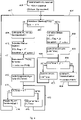
- FIG. 1 also shows a receiver unit 2 with a series resonant circuit and a further receiver unit 3 with a parallel resonant circuit whose inductances L2s and L2p are coupled to the transmitter unit 1 by inductive coupling.
- the number of two receiver units is arbitrary and shows a power transmission from a transmitter unit to at least one receiver unit. It is also arbitrary whether a receiver unit is used for coupling by means of a series or parallel resonant circuit.
- At least a part of one or more RL is changed in order to control the coupling (see dashed line in Figure 2a ).
- a main load is advantageously controlled if several partial loads determine an overall RL.
- 202 controls an operating voltage and/or the clock frequency of at least one processor in order to change its load.
- a processor can be part of a multimedia or any computer unit such.
- GPU graphics processor
- 202 controls the voltage or the current of a display backlighting by means of LEDs or 202 controls the basic brightness or contrast of an OLED display (not shown in Figure 2a ). These displays are part of mobile phones, tablets, laptops, glasses, wristband electronics or TVs. Further, 202 controls the voltage or current to charge batteries or drive motors.
- figure 4 shows the coupling regulation or coupling optimization in the event that the output voltage VOUT is not reached via RL. If the maximum VOUT is exceeded, the duty cycle in the PWM reduces to 2 and/or 3 independent of the coupling control. Alternatively or in combination, RL in 2 and/or 3 is controlled so that the maximum VOUT is not exceeded.
- VOUT is regulated via S/P without considering the control of 1 via FSKLdata.
- the OptiTimer is decremented 804 and 803 is executed again via the feedback 808 . If the end value of OptiTimer is reached, the current output variable VOUT is compared with Vcompare using the comparison 805 . If VOUT is less than Vcompare, the signal S/P changes 806 and starts 702 over 807 again. If VOUT is greater than Vcompare, then 702 starts again via 807. In this way it is guaranteed that the output variable VOUT increases steadily. Const1 sets the loop time of 702, which is a minimum of half a period of the received electromagnetic field when synchronizing via Vrs, Vrp, or Vr.
Landscapes
- Engineering & Computer Science (AREA)
- Computer Networks & Wireless Communication (AREA)
- Power Engineering (AREA)
- Near-Field Transmission Systems (AREA)
- Transmitters (AREA)
- Circuits Of Receivers In General (AREA)
- Dc-Dc Converters (AREA)
Applications Claiming Priority (3)
| Application Number | Priority Date | Filing Date | Title |
|---|---|---|---|
| DE102014019621.6A DE102014019621A1 (de) | 2014-12-29 | 2014-12-29 | Kopplungsoptimierte elektrische drahtlose Energieübertragung |
| EP18000770.0A EP3451490B1 (fr) | 2014-12-29 | 2015-11-30 | Transmission d'énergie électrique sans fil optimisée au niveau d'accouplement |
| EP15003405.6A EP3041112B1 (fr) | 2014-12-29 | 2015-11-30 | Transmission d'energie electrique sans fil a couplage optimise |
Related Parent Applications (3)
| Application Number | Title | Priority Date | Filing Date |
|---|---|---|---|
| EP15003405.6A Division EP3041112B1 (fr) | 2014-12-29 | 2015-11-30 | Transmission d'energie electrique sans fil a couplage optimise |
| EP18000770.0A Division EP3451490B1 (fr) | 2014-12-29 | 2015-11-30 | Transmission d'énergie électrique sans fil optimisée au niveau d'accouplement |
| EP18000770.0A Division-Into EP3451490B1 (fr) | 2014-12-29 | 2015-11-30 | Transmission d'énergie électrique sans fil optimisée au niveau d'accouplement |
Publications (2)
| Publication Number | Publication Date |
|---|---|
| EP4009485A2 true EP4009485A2 (fr) | 2022-06-08 |
| EP4009485A3 EP4009485A3 (fr) | 2022-08-17 |
Family
ID=54783325
Family Applications (3)
| Application Number | Title | Priority Date | Filing Date |
|---|---|---|---|
| EP15003405.6A Active EP3041112B1 (fr) | 2014-12-29 | 2015-11-30 | Transmission d'energie electrique sans fil a couplage optimise |
| EP18000770.0A Active EP3451490B1 (fr) | 2014-12-29 | 2015-11-30 | Transmission d'énergie électrique sans fil optimisée au niveau d'accouplement |
| EP21000270.5A Pending EP4009485A3 (fr) | 2014-12-29 | 2015-11-30 | Transmission d'énergie électrique sans fil optimisée au niveau de couplage |
Family Applications Before (2)
| Application Number | Title | Priority Date | Filing Date |
|---|---|---|---|
| EP15003405.6A Active EP3041112B1 (fr) | 2014-12-29 | 2015-11-30 | Transmission d'energie electrique sans fil a couplage optimise |
| EP18000770.0A Active EP3451490B1 (fr) | 2014-12-29 | 2015-11-30 | Transmission d'énergie électrique sans fil optimisée au niveau d'accouplement |
Country Status (3)
| Country | Link |
|---|---|
| US (3) | US10411511B2 (fr) |
| EP (3) | EP3041112B1 (fr) |
| DE (1) | DE102014019621A1 (fr) |
Families Citing this family (14)
| Publication number | Priority date | Publication date | Assignee | Title |
|---|---|---|---|---|
| EP2765701B1 (fr) | 2013-02-08 | 2020-01-01 | Markus Rehm | Transmission d'énergie électrique sans fil avec couplage à résonance |
| JP6437954B2 (ja) * | 2016-06-02 | 2018-12-12 | パナソニック株式会社 | 無線給電方法 |
| US10879739B2 (en) * | 2017-04-12 | 2020-12-29 | Integrated Device Technology, Inc. | Wireless power transmitter reactive energy control |
| CN108365683B (zh) * | 2018-02-10 | 2021-04-27 | 合肥工业大学 | 一种基于电流源的无线能量传输结构 |
| US12057711B2 (en) * | 2018-02-19 | 2024-08-06 | Naptilus Technology Lab, S.L. | Tuner and rectifier circuit for wireless power receiver |
| EP3528365B1 (fr) * | 2018-02-19 | 2020-07-22 | Naptilus Technology Lab, S.L. | Appareil de syntoniseur et de redresseur pour récepteur de transfert de puissance sans fil |
| US10205381B1 (en) * | 2018-05-10 | 2019-02-12 | Vlt, Inc. | Start-up control in power systems using fixed-ratio power conversion |
| US11296552B2 (en) * | 2018-06-12 | 2022-04-05 | Nanyang Technological University | Transmitter device, wireless power transfer system, and methods of forming the same |
| JP6773257B1 (ja) * | 2019-04-26 | 2020-10-21 | 三菱電機株式会社 | エレベータ |
| JP6729920B1 (ja) * | 2019-08-08 | 2020-07-29 | 株式会社レーザーシステム | 共振装置、電力伝送装置、及び電力伝送方法 |
| US11495995B2 (en) | 2019-09-23 | 2022-11-08 | Stmicroelectronics Asia Pacific Pte Ltd | Advanced overvoltage protection strategy for wireless power transfer |
| JP6849778B1 (ja) * | 2019-12-05 | 2021-03-31 | パナソニック株式会社 | 無線送電器、および無線受電器 |
| CN116057811B (zh) * | 2020-08-18 | 2024-11-19 | 微芯片技术股份有限公司 | 用于无线功率接收器的装置、无线功率接收器及其操作方法 |
| US12341984B2 (en) * | 2022-12-14 | 2025-06-24 | Qualcomm Incorporated | Truncation error signaling and adaptive dither for lossy bandwidth compression |
Family Cites Families (26)
| Publication number | Priority date | Publication date | Assignee | Title |
|---|---|---|---|---|
| JPH09326736A (ja) * | 1996-06-03 | 1997-12-16 | Mitsubishi Electric Corp | ワイヤレス送受信システム用2次側回路装置およびワイヤレス送受信システム用誘導コイル |
| US8232970B2 (en) * | 2007-01-03 | 2012-07-31 | Apple Inc. | Scan sequence generator |
| JP5340017B2 (ja) * | 2009-04-28 | 2013-11-13 | 三洋電機株式会社 | 電池内蔵機器と充電台 |
| US8390249B2 (en) * | 2009-11-30 | 2013-03-05 | Broadcom Corporation | Battery with integrated wireless power receiver and/or RFID |
| US10693853B2 (en) * | 2010-07-23 | 2020-06-23 | At&T Intellectual Property I, Lp | Method and system for policy enforcement in trusted ad hoc networks |
| KR101750415B1 (ko) * | 2010-12-16 | 2017-06-26 | 삼성전자주식회사 | 정류기를 보호하는 보호기, 상기 보호기를 포함하는 무선전력 수신 장치 |
| JP5677875B2 (ja) * | 2011-03-16 | 2015-02-25 | 日立マクセル株式会社 | 非接触電力伝送システム |
| KR101813011B1 (ko) * | 2011-05-27 | 2017-12-28 | 삼성전자주식회사 | 무선 전력 및 데이터 전송 시스템 |
| JP5840886B2 (ja) * | 2011-07-25 | 2016-01-06 | ソニー株式会社 | 検知装置、受電装置、送電装置、非接触電力伝送システム及び検知方法 |
| US9508487B2 (en) * | 2011-10-21 | 2016-11-29 | Qualcomm Incorporated | Systems and methods for limiting voltage in wireless power receivers |
| KR101304314B1 (ko) * | 2012-01-30 | 2013-09-11 | 전자부품연구원 | 임피던스 매칭이 가능한 무선 전력 송신장치 |
| US9531441B2 (en) * | 2012-02-21 | 2016-12-27 | Lg Innotek Co., Ltd. | Wireless power receiver and method of managing power thereof |
| KR101882273B1 (ko) * | 2012-05-09 | 2018-07-30 | 삼성전자주식회사 | 무선 전력 수신 장치 및 방법, 무선 전력 전송 장치 및 방법 |
| CN103683523B (zh) * | 2012-09-07 | 2018-04-13 | 捷通国际有限公司 | 用于双向无线功率传输的系统和方法 |
| CN104854771B (zh) * | 2012-10-29 | 2019-07-19 | 苹果公司 | 感应电力传输系统的接收器和用于控制该接收器的方法 |
| US9608454B2 (en) * | 2012-12-03 | 2017-03-28 | WIPQTUS Inc. | Wireless power system with a self-regulating wireless power receiver |
| EP2765701B1 (fr) * | 2013-02-08 | 2020-01-01 | Markus Rehm | Transmission d'énergie électrique sans fil avec couplage à résonance |
| US20150380978A1 (en) * | 2013-02-27 | 2015-12-31 | Nokia Corporation Oy | Wireless charger |
| JP6178107B2 (ja) * | 2013-04-30 | 2017-08-09 | 矢崎総業株式会社 | 給電システム及び共振回路 |
| CN105378498B (zh) * | 2013-07-10 | 2017-11-14 | 阿尔卑斯电气株式会社 | 蓄电装置状态估计方法 |
| EP3084915A4 (fr) * | 2013-12-20 | 2017-08-09 | Auckland Uniservices Limited | Circuit de détection de transfert de puissance inductif comportant un doubleur de courant de sortie |
| KR20160088424A (ko) * | 2014-01-07 | 2016-07-25 | 누볼타 테크놀로지 | 무선 전력 전송 시스템을 위한 고조파 감소 장치 |
| DE102014108667A1 (de) * | 2014-06-20 | 2015-12-24 | Technische Universität Braunschweig | Stromrichter und Computerprogramm |
| JP2016059115A (ja) * | 2014-09-08 | 2016-04-21 | 東芝テック株式会社 | 非接触電力伝送装置 |
| WO2016064725A1 (fr) * | 2014-10-20 | 2016-04-28 | Momentum Dynamics Corporation | Procédé et appareil de correction de facteur de puissance intrinsèque |
| EP3070536B1 (fr) | 2015-03-19 | 2019-05-01 | ETA SA Manufacture Horlogère Suisse | Mouvement horloger comprenant un dispositif d'entraînement d'un affichage analogique |
-
2014
- 2014-12-29 DE DE102014019621.6A patent/DE102014019621A1/de not_active Withdrawn
-
2015
- 2015-11-30 EP EP15003405.6A patent/EP3041112B1/fr active Active
- 2015-11-30 EP EP18000770.0A patent/EP3451490B1/fr active Active
- 2015-11-30 EP EP21000270.5A patent/EP4009485A3/fr active Pending
- 2015-12-02 US US14/757,186 patent/US10411511B2/en active Active
-
2019
- 2019-07-23 US US16/519,227 patent/US11411434B2/en active Active
-
2022
- 2022-06-21 US US17/845,413 patent/US20220360111A1/en not_active Abandoned
Also Published As
| Publication number | Publication date |
|---|---|
| US10411511B2 (en) | 2019-09-10 |
| EP3451490A1 (fr) | 2019-03-06 |
| US20220360111A1 (en) | 2022-11-10 |
| EP4009485A3 (fr) | 2022-08-17 |
| DE102014019621A1 (de) | 2016-06-30 |
| EP3041112B1 (fr) | 2019-02-06 |
| US11411434B2 (en) | 2022-08-09 |
| EP3451490B1 (fr) | 2021-11-24 |
| US20190348867A1 (en) | 2019-11-14 |
| EP3041112A1 (fr) | 2016-07-06 |
| US20160190816A1 (en) | 2016-06-30 |
Similar Documents
| Publication | Publication Date | Title |
|---|---|---|
| EP3451490B1 (fr) | Transmission d'énergie électrique sans fil optimisée au niveau d'accouplement | |
| EP2573904B1 (fr) | Oscillateur grand signal commandé en tension | |
| DE102012007477B4 (de) | Verfahren zum Betreiben eines LLC-Resonanzwandlers für ein Leuchtmittel, Wandler und LED-Konverter | |
| EP2765701B1 (fr) | Transmission d'énergie électrique sans fil avec couplage à résonance | |
| DE112019001196B4 (de) | Kontaktlose energieübertragungsvorrichtung | |
| EP3134952B1 (fr) | Système de transmission et procédé de charge par induction d'un véhicule à propulsion électrique, et ensemble véhicule | |
| EP1257048B1 (fr) | Dispositif de régulation pour convertisseur résonant | |
| DE102018109341A1 (de) | Wandler, Resonanzwandler und Verfahren | |
| DE102020118393B4 (de) | Kontaktlose energieversorgungseinrichtung | |
| DE112014004142T5 (de) | Topologie im Hochleistungsspannungsbetrieb der Klasse D | |
| DE112017005586T5 (de) | Leistungssender und Verfahren zum drahtlosen Übertragen von Leistung | |
| DE102022208903A1 (de) | Leistungssteuertechniken für drahtlose leistungsübertragung | |
| WO2016071029A1 (fr) | Systeme de transmission, procédé et système pour véhicules | |
| EP2479975B1 (fr) | Capacité de grand signal commandée et inductivité | |
| DE102012007450B4 (de) | Wandler für ein Leuchtmittel, LED-Konverter und Verfahren zum Betreiben eines LLC-Resonanzwandlers | |
| DE102018207047B4 (de) | Verfahren zum frühzeitigen erfassen eines harten schaltens und zum schützen für eine induktive stromübertragung | |
| DE112015006580T5 (de) | Spulenkonfiguration in einem Drahtlosleistungssender | |
| EP3782274B1 (fr) | Circuit de fonctionnement pour charges à led, présentant un circuit en demi-pont | |
| DE102018211033A1 (de) | Verfahren zum Betrieb einer Schaltung zur Erzeugung eines elektromagnetischen Felds und Schaltung | |
| DE112018002607B4 (de) | Kontaktlose energieversorgungsvorrichtung | |
| DE102023124453A1 (de) | Kontaktlose stromzuführvorrichtung und stromübertragungsverfahren | |
| WO2019072576A1 (fr) | Unité primaire pour un système de charge inductif, ainsi que procédé pour faire fonctionner une unité primaire | |
| EP3069571B1 (fr) | Convertisseur de del et procédé de commande d'un circuit transducteur de convertisseur de del | |
| DE112013007554T5 (de) | Resonanztyp-Hochfrequenz-Stromversorgungsvorrichtung | |
| EP1174991A2 (fr) | Convertisseur |
Legal Events
| Date | Code | Title | Description |
|---|---|---|---|
| STAA | Information on the status of an ep patent application or granted ep patent |
Free format text: STATUS: UNKNOWN |
|
| PUAI | Public reference made under article 153(3) epc to a published international application that has entered the european phase |
Free format text: ORIGINAL CODE: 0009012 |
|
| STAA | Information on the status of an ep patent application or granted ep patent |
Free format text: STATUS: REQUEST FOR EXAMINATION WAS MADE |
|
| 17P | Request for examination filed |
Effective date: 20211101 |
|
| AC | Divisional application: reference to earlier application |
Ref document number: 3041112 Country of ref document: EP Kind code of ref document: P Ref document number: 3451490 Country of ref document: EP Kind code of ref document: P |
|
| AK | Designated contracting states |
Kind code of ref document: A2 Designated state(s): AL AT BE BG CH CY CZ DE DK EE ES FI FR GB GR HR HU IE IS IT LI LT LU LV MC MK MT NL NO PL PT RO RS SE SI SK SM TR |
|
| PUAL | Search report despatched |
Free format text: ORIGINAL CODE: 0009013 |
|
| AK | Designated contracting states |
Kind code of ref document: A3 Designated state(s): AL AT BE BG CH CY CZ DE DK EE ES FI FR GB GR HR HU IE IS IT LI LT LU LV MC MK MT NL NO PL PT RO RS SE SI SK SM TR |
|
| RIC1 | Information provided on ipc code assigned before grant |
Ipc: H02J 50/00 20160101ALN20220711BHEP Ipc: H02J 50/40 20160101ALI20220711BHEP Ipc: H02J 50/12 20160101AFI20220711BHEP |
|
| STAA | Information on the status of an ep patent application or granted ep patent |
Free format text: STATUS: EXAMINATION IS IN PROGRESS |
|
| 17Q | First examination report despatched |
Effective date: 20240422 |
|
| 17Q | First examination report despatched |
Effective date: 20240426 |