EP4035744A1 - Rideau multicouche de porte coupe-feu enroulée - Google Patents
Rideau multicouche de porte coupe-feu enroulée Download PDFInfo
- Publication number
- EP4035744A1 EP4035744A1 EP22460008.0A EP22460008A EP4035744A1 EP 4035744 A1 EP4035744 A1 EP 4035744A1 EP 22460008 A EP22460008 A EP 22460008A EP 4035744 A1 EP4035744 A1 EP 4035744A1
- Authority
- EP
- European Patent Office
- Prior art keywords
- layer
- layers
- flexible
- stitching
- significant
- Prior art date
- Legal status (The legal status is an assumption and is not a legal conclusion. Google has not performed a legal analysis and makes no representation as to the accuracy of the status listed.)
- Withdrawn
Links
Images

Classifications
-
- A—HUMAN NECESSITIES
- A62—LIFE-SAVING; FIRE-FIGHTING
- A62C—FIRE-FIGHTING
- A62C2/00—Fire prevention or containment
- A62C2/06—Physical fire-barriers
- A62C2/10—Fire-proof curtains
-
- A—HUMAN NECESSITIES
- A62—LIFE-SAVING; FIRE-FIGHTING
- A62C—FIRE-FIGHTING
- A62C2/00—Fire prevention or containment
- A62C2/06—Physical fire-barriers
- A62C2/12—Hinged dampers
- A62C2/14—Hinged dampers with two or more blades
- A62C2/16—Hinged dampers with two or more blades multi-vane roll or fold-up type
Definitions
- the subject of the invention is a multi-layer curtain of a rolling fire gate.
- the invention is intended to close communication openings in buildings.
- structures in the form of gates or partitions are used, for example in the form of curtains, which, meeting strictly defined technical standards, allow for a specified and predetermined time to effectively stop the spread of fire beyond the structure used.
- Particular constructions have their specific expectations to be met, and differing in the number of elements and their interconnections, building materials, systems used, among the passive and active, as a result, they meet the demanded requirements in a correct degree, and often go beyond the assumptions.
- the juxtaposition of such constructions regardless of the specific principle of operation of each of them, results in an increase in the advancement of such a device, which results in a significant increase of costs and, consequently, the unattainability of such technical solutions.
- a barrier especially a fire-protective one in the form of a curtain, is known, made of a non-sliding shaft on which a leaf of fire-resistant and / or smoke-resistant single or multi-layer fabric separated by an insulating layer is wound.
- the leaf ends with a guide bar which moves in a sliding motion in the side guides to the bottom stop, while the curtain leaf is unrolled from the shaft, and the guide bar is driven by a flexible link, a turning pulley, a winding drum from the shaft, causing the opening which is a fire crossing to close or open, or closed with kinetic energy, in particular by gravity through a weight attached to an elastic string.
- the known leaf of a partition is a multilayer leaf made of a double fireproof layer, a double insulating layer between it and an internal slat for fixing the external slats, the external slats being attached to the internal slat so that they eliminate the formation of a thermal bridge through the leaf.
- the inconvenience related to the leaf being slabby is eliminated by the mechanism of lowering the leaf and by the weight.
- the structure, despite the slats used, does not seem to be fully protected as a solid and impervious surface.
- a curtain made of flexible material is known, intended for closing openings in buildings, especially door and window openings.
- the curtain has a leaf of elastic material. Its side edges are slidably seated in fixed groove guides placed parallel to the sides of the wall opening. The upper rim of the leaf is attached to a rotating shaft with bearing at the wall lintel.
- the inside of the guide has the form of a longitudinal groove with a bottom. The inlet portion of the groove is formed by a pair of longitudinal ribs. They face the bottom of the groove and are separated by a slot through which the lateral rim of the leaf penetrates into its interior.
- the groove has two retaining surfaces formed oppositely at the edges of its ribs on the two sides of the leaf.
- the leaf itself has retaining elements in the form of V-shaped pads with a V-shape, which are attached to its side edges. The open arms of the pads glide against the supporting surfaces of the ribs.
- This construction solves the disadvantage of the more difficult keeping the slabby edges of the leaf in the side guides. Still, the coating is not resistant to mechanical damage, especially tearing caused by cutting or puncturing the leaf.
- a barrier especially a fire barrier, in the form of a curtain, installed on an opening constituting a fire crossing.
- the partition has a leaf wound on a winding shaft and is equipped with a winding shaft drive that enables the leaf to be unrolled and wound on, while the leaf, during unfolding or rolling up, moves in contact with fixed guides attached to the wall or other fixed construction element near the opening.
- the leaf is attached with one end to the upper edge of the opening, which constitutes a fire crossing, preferably to the lintel, and the other end is wound on a movable and driven winding shaft, the axis of which, when moving, performs both sliding and rotary motion.
- Another Polish patent, Pat.225561 describes a leaf of a fire gate, used in various types of buildings, especially in warehouses, commercial or service facilities.
- the leaf of the fire gate is made of chain-linked, flexible, plate-shaped, multi-layer sections. Its adjacent segments are permanently connected by flexible joints, each joint consisting of a flat, transversely bent periphery of a segment which is recessed in a U-shaped gusset formed on the transverse curved periphery of an adjacent segment.
- the fastener of each joint is a wire staple, threaded across the walls of the fold and the flat rim of the segment recessed into it.
- a curtain is known, especially a fire-resistant curtain for partitioning interior spaces in buildings and closing communication openings.
- the fire curtain is equipped with a leaf which consists of longitudinal and side-joined strands of flexible material, in particular fire-resistant glass fabric.
- the longitudinal edges of the material bands are overlapped and interconnected by seams which are parallel, arranged in pairs and spaced apart.
- flat, flexible stiffening strips are embedded in the pockets formed between each pair of seams at the boundary of the adjacent bands of material. These strips are also located in pockets formed in the folded-up outer edges of the coat.
- a fire-rated rolling gate equipped with a pair of fire-resistant curtains, which are attached to two horizontal winding shafts mounted with bearings on both sides of the lintel of the opening in the wall of the building.
- Each curtain consists of two adjacent and mutually bonded flexible multi-layer leaves, and a spaced apart single-layer flexible leaf made of a fire-resistant fabric.
- Each multi-layer leaf consists of a fire-resistant load-bearing layer, a heat-insulating layer and two reflective layers. All the leaves of each curtain are attached to the respective one or the other common shaft.
- a space is formed in the lower part of the casing of each winding shaft which separates the composite multi-layer leaves of each curtain from its single-layer leaf.
- FIG. 233242 Another Polish patent, Pat. No. 233242 , describes a fireproof partition, made of many layers of flexible fireproof material, which is used to close communication openings in the walls of buildings and to protect rooms against the spread of fire.
- the fireproof partition consists of at least one load-bearing layer as well as at least one top layer and / or at least one intermediate layer which are formed of fireproof material.
- the load-bearing layer is at least on one side covered with an intumescent coating made of a material which expands upon increasing temperature.
- each of the covers is tilted from its surface and rests with its free edge against the surfaces of the adjacent surface layer and / or an intermediate layer.
- the present solution seems to be a solution with additional protection which increases the volume and thus the securing space. It seems, therefore, that this solution is mechanically more stable than the previous ones, although it probably still does not achieve as high resistance to mechanical damage as structures with a steel jacket.
- a multi-layer flexible curtain of a rolling fire gate is known, intended for closing communication openings in buildings.
- the curtain has an outer, load-bearing layer, which determines the tearing strength of the curtain, and an insulating layer that determines its thermal insulation properties, which are connected with each other by horizontal, parallel stitching, which constitute horizontal lamellas, which, when wound up, do not shift the individual layers of the flexible leaf.
- horizontal, parallel stitching which constitute horizontal lamellas, which, when wound up, do not shift the individual layers of the flexible leaf.
- both flexible layers are independent of each other, and wind up on one and the same horizontally mounted, rotating shaft set above the opening in the wall of the building.
- the curtain is therefore more prone to tearing when it is in the unfold position, but unexpectedly, thanks to the narrow lamellas and stitching, it is less exposed to abrasions during the operation of winding it up and unrolling it from the rotating shaft. It is known that the more layers of a curtain and the more they are differentiated by their structure, in particular by stiffness, the more their layers are exposed to abrasion during the rolling and unrolling operation. The lack of allowance for adjacent layers has a positive effect on this disadvantage.
- the fireproof wall consists of panes or plates fixed in aluminum chamber profiles filled with heat-resistant material and provided with sealing elements. Fire-resistant panes and panes or sheets and plates covered with sheet steel are embedded in a frame formed by two types of modules connected together, a marginal one and an intermediate one.
- Each module has a cross-section similar to a rectangle and consists of a set of cellular aluminum profiles: a base profile, two side profiles and at least one middle profile.
- the base profile has a cross-section similar to two Hs, lying side by side with external hooks near the horizontal lines.
- the side profile is a C-section with internal longitudinal projections
- the middle profile is a C-section with internal projections along the ends of the arms and with external guides.
- the profiles are filled with wooden laths with a rectangular cross-section, preferably protected with fireproofing impregnation. These solutions, first after a number of elastic fabric ones, are significantly stronger mechanically.
- the chamber aluminum profiles provide this strength, but on the other hand, they significantly increase the own weight of the fireproof wall. Considering the comparison with the construction based only on elastic materials, it may be increased several times. This significantly changes the need to construct load-bearing elements for operating such a solid wall. The requirement is becoming larger cross-sections of profiles, catches, etc. This causes a further increase in the weight of the structure understood as a whole.
- the sliding fire gate comprises a sliding leaf which is made up of a plurality of adjacent, preferably sandwich panels. Each of these plates is preferably delimited on the outside by a sheath and the inside of the plate is preferably filled with insulating material.
- the boards are arranged parallel to each other, all of them permanently connected to each other and suspended on a horizontal guide.
- the plates are mounted parallel to the guide and at the same time parallel to the ground and the direction of travel, and possibly there is at least one wedging point within the wing in the retracted position at the edge of the wing remote from the guide, and at least the wing optionally has circumferential reinforcements.
- This solution shows a panel structure which can be a foldable structure, and as a solid structure, in particular with a double-sided armor, it is not without the drawbacks described in the previous solution.
- RGS discloses a fire barrier with a cassette multi-element structure, where the individual cassettes are hinged to each other and are wound on a rotating shaft mounted above the passageway, which is protected by the partition.
- Each cassette has a filling inside, thanks to which the partition has protective properties, i.e. anti-fire and / or protecting against smoke in the area.
- the partition is wound on the shaft cassette by the cassette so that the individual cassettes in the unfolded position are adjacent to each other one above the other, and in the rolled form, successive rings of cassettes wound in a spiral on the rotating shaft touch each other, concealing located in the cassette located above the opening, protected by a partition, as a passage or passage between adjacent rooms of the building.
- seals There is usually a seal between adjacent cassettes, which makes it an independent element exposed to the fire power of a possible fire.
- the seal may independently, during the folding and unfolding cycles, be exposed to depriving of its sealing properties due to e.g. compression, and thus may form a longitudinal thermal bridge. If, instead of a gasket, adjacent panels have a solid, continuous, one fire-resistant layer running through all the panels, then this layer is particularly exposed to mechanical damage, such as tearing or permanent compression, which will equally limit its functionality.
- the aim of the present invention is to set up structures for just such a hybrid achievement of the benefits of the properties of flexible curtains and gates with steel or aluminum armor.
- the goal is, despite the combination of such a structure, to keep the weight of the new product as low as possible, and at the same time to ease the assembly of the structure and the possibility of its use in architecturally difficult to reach target foundations, i.e. in narrow passages, but also in very wide, which makes the invention
- the versatility should also result from the possibility of placing the barrier according to the present invention in places with a negligible amount of free space for mounting the cassette to a rotating shaft, on which the rolled-up partition can be accommodated.
- the advantage of the solution should be that despite the many layers, and despite the different building material of the layers, none of them will prematurely rub, tear, or mechanically puncture, and all of them should easily be rolled up on the shaft and hidden in the cassette with the help of the drive installed for this purpose, or possibly with the help of hands, if, in the case of small dimensions, the engine was not an indispensable booster.
- a multi-layer curtain of a rolling fire gate is designed to close communication openings in buildings. It comprises of at least one flexible load-bearing layer, preferably located externally, and includes at least one flexible insulating layer, preferably located internally, determining its thermal insulation properties, the flexible load-bearing layer being, together with the flexible insulating layer, wound on one and the same rotating shaft embedded in the casette above the communication opening, and the elastic layers are connected with each other by horizontal, parallel stitching. Between the stitching, horizontal lamellas are formed, during the winding of which the layers preferably do not shift. The layers, apart from the places of stitching, are preferably free to each other.
- the solution is characterized by the fact that it has additionally one main outer layer of metal armor composed of hinged, longitudinally, horizontally connected metal sheets, which constitute the tear strength of the curtain, and are also compatible with continuous elastic layers connected by stitching.
- the layers are wound onto the shaft so that the inner layer of the spiral wound is a flexible support layer, and the outer layer of the spiral wound is the main metal armor layer, between which there is at least one insulating layer and possibly additional flexible support layers, when both in the unfolded and folded position of all layers, the main layer of the metal armor is a layer that hangs freely and is wound on in relation to the elastic layers, respectively.
- the lamella has a rectangular shape on the surface.
- the lamella is a separated, but jointly movable, rectangular part of the metal armor layer and the corresponding part of the elastic layers connected by stitching, located jointly between adjacent, delimiting stitching and, respectively, hinge connections.
- the hinged joint is a self-supporting two-element clasp, the first element of which is a profiled open and more tightly wound, incomplete inner loop, and the second element is an open and appropriately fitted to the previous, wider, incomplete outer loop, of which the inner loop, constituting an extension of the flat metal armor lamella, is coaxially fitted inside the outer loop extending from the adjacent successive metal armor lamella.
- the sheets of the metal armor layer are made of steel, preferably acid-resistant steel or aluminum.
- the thickness of the plates is equal, and preferably the plate is thicker than 0.4 mm.
- the sheet has longitudinal reinforcement ribbing, the ribbing depth preferably not exceeding the sheet thickness.
- the metal armor layer on at least one of its lamellas is openwork.
- the flexible support layer is an edge fabric for the flexible insulating layer, constituting at least one side of it as a wrapper.
- the flexible support layer constituting the edge fabric of the flexible insulating layer is made as a glass mat, preferably reinforced with a metal wire.
- the elastic support layer constituting the edge fabric of the flexible insulating layer is an additional supporting insulating layer.
- the flexible insulating layer is made of a non-intumescent insulating material, preferably stone wool or glass wool, or intumescent insulating material.
- the stitching is point or the stitching is linear.
- the stitching is made of elastic material or the stitching is made of wire or cord, preferably metal.
- the flexible insulating layer preferably together with the flexible support layer, embraces hinge joints as a continuation.
- the curtain is unrolled by gravity unfolding after releasing the lock in the bottom of the cassette, while it is rolled up by a shaft driven by a manual link or a motor, preferably electric.
- the height of the lamella does not exceed 12 cm, preferably it does not exceed 5 cm.
- the horizontally and longitudinally placed hinge connections both in the position of the unfolded layers and in the position of the layers rolled up on the shaft, respectively the base layer, the insulating layer, the main layer of the metal armor, correspond to the position of the stitching of the elastic layers, being placed vis a vis them within the selected lamella.
- the undoubted advantage of the solution apart from all those indicated as the curtain's functionality, is also the fact that when the curtain according to the invention is wound on a rotating shaft, the tearing of the continuous and flexible insulating layer does not take place, but only its centric pressure towards the shaft, because it is first wound on the shaft, and the metal armor adheres to it as a lamella element - due to its nature, the flexible supporting layer additionally protects the flexible insulating layer.
- the advantage is the narrow width of the lamellas, thanks to which the metal armor does not bend, and the cassette may remain small, also due to the thin thickness of the metal armor plates.
- the structure is still light, despite the fact that it has a metal armor as a mechanical protection function, which makes it possible to protect the insulating layer in the best possible way, which is a flexible and functional layer in terms of fire protection.
- the whole thing is limited to the constructional minimum, and at the same time it fulfills both the functions of an armored curtain and a flexible curtain, summing up their advantages and eliminating unexpected disadvantages.
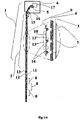
- Fig. 1 shows the curtain from the first example, in a vertical section unrolled from a shaft, in the most basic version, i.e. with one armor layer, one flexible insulation layer and one flexible load-bearing layer
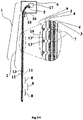
- Fig.2 shows the curtain from the second example, in a vertical section unrolled from the shaft, in an enriched version, protecting the insulation layer, i.e. with one armor layer, one flexible insulation layer and two flexible load-bearing layers constituting a wrapper of the insulation layer
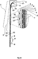
- Fig. 3 shows the curtain from the third example in a vertical section, unrolled from the shaft, in the version extending the fire protection, i.e.
- FIG. 4 shows the curtain from the fourth example, in a vertical section unrolled from a shaft, in a redundant design, both extending fire protection and securing protective functions, i.e. with one armor layer, two flexible insulating layers placed next to each other, however, as independently pre-made groups of flexible layers, i.e. each with two flexible load-bearing layers placed externally on each of the flexible insulating layers, where the double load-bearing layers in each case constitute the full wrapper of each individual flexible insulation layer.
- An exemplary multi-layer curtain 2 of a rolling fire gate 1 is designed to close communication openings in buildings. It comprises one flexible load-bearing layer 3 positioned externally and comprises one flexible insulating layer 4 positioned internally, wherein the flexible load-bearing layer 3 is, together with the flexible insulating layer 4, wound onto one and the same rotating shaft 5 embedded in the cassette 6 above the communication opening.
- the two elastic layers 3,4 are connected with each other by horizontal, parallel stitching 7. Between the stitching 7, horizontal lamellae 8 are formed, during the winding of which the layers 3,4 do not shift.
- the layers 3, 4, apart from the places where they are seamed, are free to each other.
- the curtain 2 additionally has one main outer layer of metal armor 9 composed of hinged, longitudinally, horizontally connected metal sheets 10, which constitute the tear strength of the curtain 2, and are also compatible with continuous elastic layers 3,4 connected by stitching 7 All layers 3, 4, 9 are wound on the shaft 5 so that the inner layer 11 of the spiral wound is a flexible support layer 3, and the outer layer 12 of the spiral wound is the main metal armor layer 9, between which there is one flexible insulating layer. 4, of which, both in the unfolded position and in the folded position of all layers 3, 4, 9, the main layer of the metal armor 9 is a layer, respectively, freely hanging and wound in relation to the elastic layers 3, 4.
- the surface of the lamella 8 is rectangular.
- the lamella 8 is separated, but jointly movable, rectangular part of the metal armor layer 9 and the corresponding part of the 7 elastic layers connected by stitching 7, located jointly between the adjacent, delimiting stitching 7 and, respectively, hinge connections 13. This time the lamellas 8 are exactly fifteen pieces hanging vertically under the cassette 6, in the opening, and two more in the cassette 6, the top of which is hooked to the shaft 5 of the cassette 6. The height of each lamella 8 does not exceed 12 cm, this time it is 10cm.
- Each hinged joint 13 is a self-supporting two-element clasp, the first element of which is a profiled open and more tightly wound incomplete inner loop 13 ', and the second element is an open and appropriately fitted to the previous, wider, incomplete outer loop 13 ", of which the inner loop 13' is the extension of the flat metal armor 9 plate 10 is coaxially mounted inside the outer loop 13 "extending from the adjacent further metal armor plate 10 of the metal armor 9 layer.
- the plates 10 of the metal armor layer 9 are made of steel, this time acid-resistant steel.
- the thickness of the plates 10 is equal, the plate 10 is thicker than 0.4 mm, this time exactly 1 mm.
- the metal sheet 10 has longitudinal ribbing 14, the depth of the reinforcing ribs 14 not exceeding the thickness of the metal sheet 10.
- the metal armor layer 9 on at least one of its sheets 10 is openwork, this time on the four middle ones.
- the flexible support layer 3 is an edge fabric for the flexible insulating layer 4, constituting its wrapper on one side.
- the flexible support layer 3, constituting the edge fabric of the flexible insulating layer 4, is made as a glass mat, reinforced with a metal wire.
- the flexible support layer 3 which is the edge fabric of the flexible insulating layer 4 is an additional supporting insulating layer, this time protecting against heat.
- the flexible insulating layer 3 is made of a non-intumescent insulating material, this time of stone wool.
- the stitching 7 is point-like and is made of an elastic material.
- the curtain 2 is unrolled by gravity unfolding after release locks 15 in the bottom 16 of the cassette 6, while it is wound by the shaft 5 driven by an electric motor 17.
- the curtain 2 in the range of elastic layers 3,4 includes two elastic load-bearing layers 3, placed externally, and includes one flexible insulating layer 4, placed internally between the flexible load-bearing layers 3.
- Flexible load-bearing layers 3 constitute the wrapper of the insulation layer 4, All layers 3,4 9 are wound onto the shaft such that the inner layer 11 of the spiral wound, with the protected opening on the left front side of the curtain 2, is the rightmost flexible support layer 3, and the outer layer 12 of the spiral wound is the main metal armor layer 9 between which there is from left to right one additional flexible supporting layer 3 and one flexible insulating layer 4.
- the sheets 10 of the metal armor layer 9 are made of aluminum. The thickness of the plates 10 is equal, the plate 10 is thicker than 0.4 mm, this time exactly 0.5 mm.
- the metal sheet 10 has no reinforcement ribs 14, except for the hinge joints 13.
- the metal armor layer 9 is solid.
- the flexible load-bearing layer 3 is an edge fabric for the flexible insulating layer 4, constituting its wrapper on both sides.
- the flexible insulating layer 4 is made of a non-intumescent insulating material, this time glass wool.
- the stitches 7 are linear and are made of a metal cord.
- the curtain 2 in the area of elastic layers 3,4 includes two elastic load-bearing layers 3, placed externally, and includes two flexible insulating layers 4, placed internally between the flexible load-bearing layers 3.
- Flexible load-bearing layers 3 constitute the wrapping of both elastic insulating layers 4, All layers 3,4,9 are wound onto shaft 5 such that the inner layer 11 of the spiral wound, with the protected opening on the left front side of the curtain 2, is the rightmost flexible support layer 3, and the outer layer 12 of the spiral wound is the main layer metal armor 9, between which there is from left to right one additional flexible load-bearing layer 3 and two flexible insulating layers 4.
- the sheets 10 of the metal armor layer 9 are made of steel.
- the thickness of the plates 10 is equal, but the plate 10 is not thicker than 0.4 mm, because this time it is exactly 0.4 mm.
- the flexible insulating layer 4 is made of intumescent insulating material.
- the stitches 7 are linear and are made of metal wire.
- the curtain 2 in the area of elastic layers 3,4 comprises four flexible load-bearing layers 3, placed externally for each of the two flexible insulating layers 4.
- Flexible load-bearing layers 3 constitute the wrapping of both insulation layers 4, All layers are wound on the shaft 5 so that the inner layer 11 of the spiral wound coil, with the protected opening located on the left front side of the curtain 2, is the rightmost flexible load-bearing layer 3, and the outer layer 12 of the spiral wound is the main layer of metal armor 9, between which there is one left to right one.
- Double load-bearing layers 3 each form a full wrapper of each flexible insulation layer 4 separately.
Landscapes
- Health & Medical Sciences (AREA)
- Public Health (AREA)
- Business, Economics & Management (AREA)
- Emergency Management (AREA)
- Special Wing (AREA)
Applications Claiming Priority (1)
| Application Number | Priority Date | Filing Date | Title |
|---|---|---|---|
| PL436790A PL246522B1 (pl) | 2021-01-27 | 2021-01-27 | Wielowarstwowa kurtyna rolowanej bramy przeciwpożarowej |
Publications (1)
| Publication Number | Publication Date |
|---|---|
| EP4035744A1 true EP4035744A1 (fr) | 2022-08-03 |
Family
ID=80685133
Family Applications (1)
| Application Number | Title | Priority Date | Filing Date |
|---|---|---|---|
| EP22460008.0A Withdrawn EP4035744A1 (fr) | 2021-01-27 | 2022-01-27 | Rideau multicouche de porte coupe-feu enroulée |
Country Status (2)
| Country | Link |
|---|---|
| EP (1) | EP4035744A1 (fr) |
| PL (1) | PL246522B1 (fr) |
Cited By (1)
| Publication number | Priority date | Publication date | Assignee | Title |
|---|---|---|---|---|
| EP4685330A1 (fr) * | 2024-07-26 | 2026-01-28 | McKeon Rolling Steel Door Co., Inc. | Ensemble de rideau coupe-feu à enroulement multicouche |
Citations (12)
| Publication number | Priority date | Publication date | Assignee | Title |
|---|---|---|---|---|
| FR2260733A1 (en) * | 1974-02-08 | 1975-09-05 | Rech Ventil Aeraulique Et | Flexible fire proof curtain for distribution duct - has mineral wool core between steel sheets guided by guides |
| DE2901400B1 (de) * | 1979-01-15 | 1980-06-12 | Herbert Effertz-Lex | Feuer- und waermedaemmender aufrollbarer Abschluss |
| PL220837A3 (fr) | 1979-12-28 | 1981-07-24 | Politechnika Warszawska | |
| PL230346A1 (fr) | 1981-03-25 | 1981-09-18 | Kopalnia Wegla Kamiennego Czer | |
| PL224583A1 (fr) | 1980-05-29 | 1981-12-11 | B St I P Przemyslowych Urzadze | |
| PL225561A1 (fr) | 1980-07-09 | 1982-02-15 | Zaklad Badawczo Rozwojowy Polm | |
| PL226514A1 (fr) | 1980-08-30 | 1982-03-01 | Inst Chemii Nieorganicznej | |
| PL228349A1 (fr) | 1980-12-08 | 1982-06-21 | Inst Obrobki Plastycznej | |
| PL233242A1 (en) | 1981-09-28 | 1983-04-11 | Akad Gorniczo Hutnicza | Method of determining machine component degree of fatigue |
| PL398438A1 (pl) | 2012-03-14 | 2013-09-16 | Zenon Malkowski | Kurtyna zwijana |
| PL406688A1 (pl) | 2013-12-20 | 2015-06-22 | Anna Banach | Przegroda, zwłaszcza przeciwpożarowa i płaszcz przegrody, zwłaszcza przeciwpożarowej |
| PL411445A1 (pl) | 2015-03-02 | 2016-09-12 | Zenon Małkowski | Brama rolowana przeciwpożarowa |
-
2021
- 2021-01-27 PL PL436790A patent/PL246522B1/pl unknown
-
2022
- 2022-01-27 EP EP22460008.0A patent/EP4035744A1/fr not_active Withdrawn
Patent Citations (12)
| Publication number | Priority date | Publication date | Assignee | Title |
|---|---|---|---|---|
| FR2260733A1 (en) * | 1974-02-08 | 1975-09-05 | Rech Ventil Aeraulique Et | Flexible fire proof curtain for distribution duct - has mineral wool core between steel sheets guided by guides |
| DE2901400B1 (de) * | 1979-01-15 | 1980-06-12 | Herbert Effertz-Lex | Feuer- und waermedaemmender aufrollbarer Abschluss |
| PL220837A3 (fr) | 1979-12-28 | 1981-07-24 | Politechnika Warszawska | |
| PL224583A1 (fr) | 1980-05-29 | 1981-12-11 | B St I P Przemyslowych Urzadze | |
| PL225561A1 (fr) | 1980-07-09 | 1982-02-15 | Zaklad Badawczo Rozwojowy Polm | |
| PL226514A1 (fr) | 1980-08-30 | 1982-03-01 | Inst Chemii Nieorganicznej | |
| PL228349A1 (fr) | 1980-12-08 | 1982-06-21 | Inst Obrobki Plastycznej | |
| PL230346A1 (fr) | 1981-03-25 | 1981-09-18 | Kopalnia Wegla Kamiennego Czer | |
| PL233242A1 (en) | 1981-09-28 | 1983-04-11 | Akad Gorniczo Hutnicza | Method of determining machine component degree of fatigue |
| PL398438A1 (pl) | 2012-03-14 | 2013-09-16 | Zenon Malkowski | Kurtyna zwijana |
| PL406688A1 (pl) | 2013-12-20 | 2015-06-22 | Anna Banach | Przegroda, zwłaszcza przeciwpożarowa i płaszcz przegrody, zwłaszcza przeciwpożarowej |
| PL411445A1 (pl) | 2015-03-02 | 2016-09-12 | Zenon Małkowski | Brama rolowana przeciwpożarowa |
Cited By (1)
| Publication number | Priority date | Publication date | Assignee | Title |
|---|---|---|---|---|
| EP4685330A1 (fr) * | 2024-07-26 | 2026-01-28 | McKeon Rolling Steel Door Co., Inc. | Ensemble de rideau coupe-feu à enroulement multicouche |
Also Published As
| Publication number | Publication date |
|---|---|
| PL246522B1 (pl) | 2025-02-10 |
| PL436790A1 (pl) | 2022-08-01 |
Similar Documents
| Publication | Publication Date | Title |
|---|---|---|
| US4397347A (en) | Foldable panel or door | |
| KR20160064056A (ko) | 건축물 개구부 용 듀얼 패브릭 커버링 | |
| IT9035586U1 (it) | Serranda arrotolabile e pieghevole. | |
| DE102015117548B4 (de) | Verschlussvorrichtung und Verfahren zur Montage einer Verschlussvorrichtung für eine Bauwerksöffnung | |
| EP4035744A1 (fr) | Rideau multicouche de porte coupe-feu enroulée | |
| AU2020268212B2 (en) | A fire barrier assembly and method of use thereof | |
| CN214740980U (zh) | 一种防火卷帘门 | |
| EP3679987B1 (fr) | Fermeture coupe-feu | |
| DK2474683T3 (en) | Fire-resistant closure | |
| ES2972121T3 (es) | Puerta de persiana resistente al fuego, edificio y lama resistente al fuego para una puerta de persiana resistente al fuego | |
| CN221144165U (zh) | 一种封闭式防火卷帘 | |
| EP3674511A1 (fr) | Système de fermeture de protection contre l'incendie du type rideau coupe-feu équipé d'un manteau avec chambre isolante | |
| JP7780927B2 (ja) | 開閉装置 | |
| JP3418129B2 (ja) | 開閉装置 | |
| AU2010202416B2 (en) | Improvements relating to Roller Doors | |
| CN112302514A (zh) | 一种水平防火卷帘门及其使用方法 | |
| PL244354B1 (pl) | Przeciwpożarowa kurtyna harmonijkowa | |
| US20250076007A1 (en) | Rollup Bullet Proof/Cut Resistant Panel | |
| KR20210013385A (ko) | 차열 강화 방화셔터 | |
| RU239865U1 (ru) | Светопрозрачная противопожарная ограждающая конструкция | |
| JPH0642681Y2 (ja) | 可動式防火壁 | |
| RU203746U1 (ru) | Устройство вертикального развертывания шиберного ограждения отсечки пламени пожара | |
| PL222896B1 (pl) | Elastyczny płaszcz bramy zwłaszcza kurtyny rolowanej | |
| RU117488U1 (ru) | Дверь | |
| KR20250055078A (ko) | 오버헤드 오픈식 방화문 |
Legal Events
| Date | Code | Title | Description |
|---|---|---|---|
| PUAI | Public reference made under article 153(3) epc to a published international application that has entered the european phase |
Free format text: ORIGINAL CODE: 0009012 |
|
| STAA | Information on the status of an ep patent application or granted ep patent |
Free format text: STATUS: THE APPLICATION HAS BEEN PUBLISHED |
|
| AK | Designated contracting states |
Kind code of ref document: A1 Designated state(s): AL AT BE BG CH CY CZ DE DK EE ES FI FR GB GR HR HU IE IS IT LI LT LU LV MC MK MT NL NO PL PT RO RS SE SI SK SM TR |
|
| STAA | Information on the status of an ep patent application or granted ep patent |
Free format text: STATUS: REQUEST FOR EXAMINATION WAS MADE |
|
| 17P | Request for examination filed |
Effective date: 20230127 |
|
| RBV | Designated contracting states (corrected) |
Designated state(s): AL AT BE BG CH CY CZ DE DK EE ES FI FR GB GR HR HU IE IS IT LI LT LU LV MC MK MT NL NO PL PT RO RS SE SI SK SM TR |
|
| R17P | Request for examination filed (corrected) |
Effective date: 20220127 |
|
| STAA | Information on the status of an ep patent application or granted ep patent |
Free format text: STATUS: EXAMINATION IS IN PROGRESS |
|
| 17Q | First examination report despatched |
Effective date: 20230823 |
|
| STAA | Information on the status of an ep patent application or granted ep patent |
Free format text: STATUS: THE APPLICATION IS DEEMED TO BE WITHDRAWN |
|
| 18D | Application deemed to be withdrawn |
Effective date: 20240103 |