EP4040054A1 - Climatiseur à montage mural - Google Patents
Climatiseur à montage mural Download PDFInfo
- Publication number
- EP4040054A1 EP4040054A1 EP21203586.9A EP21203586A EP4040054A1 EP 4040054 A1 EP4040054 A1 EP 4040054A1 EP 21203586 A EP21203586 A EP 21203586A EP 4040054 A1 EP4040054 A1 EP 4040054A1
- Authority
- EP
- European Patent Office
- Prior art keywords
- main body
- holding member
- body casing
- wall
- unit
- Prior art date
- Legal status (The legal status is an assumption and is not a legal conclusion. Google has not performed a legal analysis and makes no representation as to the accuracy of the status listed.)
- Granted
Links
Images


Classifications
-
- F—MECHANICAL ENGINEERING; LIGHTING; HEATING; WEAPONS; BLASTING
- F24—HEATING; RANGES; VENTILATING
- F24F—AIR-CONDITIONING; AIR-HUMIDIFICATION; VENTILATION; USE OF AIR CURRENTS FOR SCREENING
- F24F1/00—Room units for air-conditioning, e.g. separate or self-contained units or units receiving primary air from a central station
- F24F1/0007—Indoor units, e.g. fan coil units
- F24F1/0043—Indoor units, e.g. fan coil units characterised by mounting arrangements
- F24F1/0057—Indoor units, e.g. fan coil units characterised by mounting arrangements mounted in or on a wall
-
- F—MECHANICAL ENGINEERING; LIGHTING; HEATING; WEAPONS; BLASTING
- F24—HEATING; RANGES; VENTILATING
- F24F—AIR-CONDITIONING; AIR-HUMIDIFICATION; VENTILATION; USE OF AIR CURRENTS FOR SCREENING
- F24F13/00—Details common to, or for air-conditioning, air-humidification, ventilation or use of air currents for screening
- F24F13/20—Casings or covers
-
- F—MECHANICAL ENGINEERING; LIGHTING; HEATING; WEAPONS; BLASTING
- F24—HEATING; RANGES; VENTILATING
- F24F—AIR-CONDITIONING; AIR-HUMIDIFICATION; VENTILATION; USE OF AIR CURRENTS FOR SCREENING
- F24F13/00—Details common to, or for air-conditioning, air-humidification, ventilation or use of air currents for screening
- F24F13/32—Supports for air-conditioning, air-humidification or ventilation units
Definitions
- the present disclosure relates to a wall-mounted air conditioner with improved workability during installation of an interior unit of the air conditioner.
- PTL 1 discloses an installation apparatus for an air conditioner capable of improving workability of piping work and wiring work for an interior unit.
- the installation apparatus includes a plurality of hook portions provided on the back surface of the interior unit.
- the plurality of hook portions are locked to a mounting plate fixed to a wall surface of a house.
- One of the plurality of hook portions is disposed at a substantial center of gravity of the interior unit.
- PTL 2 discloses an air conditioner that effectively uses a support member that supports an interior unit in an inclined state during piping work after the support member is used as a brace.
- the support member of the air conditioner includes a base rotatably attached to a back surface of the interior unit, a tension portion extending from the base, a contact portion that is bent from a tip of the tension portion and brought into contact with an installation frame, and a pipe support portion extending from the contact portion.
- the present disclosure provides a wall-mounted air conditioner that improves workability of piping work and wiring work for an indoor unit, reduces a depth size, and improves energy saving performance.
- a wall-mounted air conditioner includes: a main body casing including first and second side end portions disposed respectively on opposite sides to each other in a horizontal direction, and a central portion disposed between the first and second side end portions; a heat exchanger disposed in the central portion of the main body casing; a fan motor disposed in the first side end portion of the main body casing; a mounting plate having a locking unit for locking the main body casing, the locking unit being disposed at an upper portion of the mounting plate; and a holding member configured to hold the main body casing in an inclined state where the main body casing is locked to the locking unit during installation.
- the main body casing includes a holding member containing unit configured to contain the holding member, and a rotational supporting unit having a horizontal shaft engaged with the holding member.
- the holding member is disposed in a position, the position being in the second side end portion of the main body casing and on a side of a back surface of the main body casing.
- the holding member includes a rotational shaft unit using the horizontal shaft as an axis. The holding member rotates upward to be contained in the main body casing.
- the wall-mounted air conditioner includes the holding member on a side opposite in front view to the fan motor across the heat exchanger.
- the wall-mounted air conditioner is able to effectively use a storage space in a depth direction of the electric part, and may increase an effective length of the heat exchanger.
- the wall-mounted air conditioner can employ a heat exchanger having a large cross-sectional area.
- the holding member rotates upward, to a direction that does not relate to a space in which the pipe is disposed, and is stored in the main body casing. The worker is able to carry out the piping work easily. Therefore, it is possible to reduce the depth size of the interior unit, improve the energy saving performance, and improve the workability during installation of the interior unit.
- the holding member is often provided at a substantial central portion or a substantial center of gravity of the indoor unit, and thus, a space for disposing those installation members and the locking unit is required. Therefore, the installation members and the locking unit are located on a side of the back surface of the heat exchanger. It is necessary to dispose the heat exchanger and this space so as not to interfere with each other. An area of a heat-transfer portion of the stored heat exchanger cannot be increased, and it is difficult to increase the volume of the heat exchanger.
- the holding member when the holding member is disposed on the back side of the electric part or the fan motor, the board or the like contained in the electric part cannot be made larger in the depth direction.
- the board or the like contained in the electric part cannot be made larger in the depth direction.
- the electric part may be arranged in front of the heat exchanger.
- such an arrangement is difficult in a thin model having a reduced depth.
- a support member for holding the inclined state during installation rotates in a downward direction different from the side of the back surface of the heat exchanger and is stored in the piping space.
- the piping space corresponds to a space defined by an air supply passage connected to a blow-out port of the air conditioner, a side of a back surface of a heat insulating material that insulates the air supply passage from heat, and an indoor wall surface.
- the piping space can be made sufficiently large.
- the piping space cannot be made large. Therefore, it is difficult to secure a space for storing the support member that holds the inclined state during installation.
- a work space is small, the work for storing the support member cannot be easily carried out.
- the wall-mounted air conditioner having a reduced depth size is desired to have a heat exchanger with an increased volume.
- the volume of the heat exchanger cannot be increased, because the space for the holding member and the locking unit for locking the holding member and the space for storing the holding member in the interior unit are required.
- the inventor has found this problem, and has made the subject matter of the present disclosure in order to solve this problem.
- the present disclosure provides a wall-mounted air conditioner that improves workability for an indoor unit during piping work, wiring work, and the like, reduces the depth size, and improves energy saving performance
- a first exemplary embodiment will be described below with reference to FIGS. 1 to 7 .
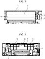
- FIG. 1 is a front view of a wall-mounted air conditioner.
- FIG. 1 illustrates the wall-mounted air conditioner with front frame 2 (see FIG. 6 ) and a blow-out grill removed, so that an arrangement of members in main body casing 1 can be seen.
- FIG. 2 is a back view of the wall-mounted air conditioner.
- the wall-mounted air conditioner includes main body casing 1.
- Main body casing 1 has a first side end portion and a second side end portion opposite to each other in the horizontal direction, and a central portion positioned between the first side end portion and the second side end portion.
- the wall-mounted air conditioner includes heat exchanger 3 in the central portion.
- the wall-mounted air conditioner includes fan motor 4 in the first side end portion.
- the wall-mounted air conditioner includes holding member containing unit 1b that contains holding member 7 in the second side end portion.
- the wall-mounted air conditioner further includes a cross flow fan (not shown), and electric part 5 that contains a drive power supply that drives fan motor 4, a control board, and the like.
- the cross flow fan is rotationally driven by fan motor 4, indoor air is taken through an intake port provided by front frame 2, and air that is heat-exchanged by heat exchanger 3 is blown into the room through a blowout port.
- heat exchanger 3 During cooling operation in which heat exchanger 3 functions as an evaporator, heat exchanger 3 generates condensed water in which moisture in the air is condensed.
- the condensed water is collected in a drain pan provided by main body casing 1, the blow-out grill, and the like, and is discharged outside the room through a drain hose connected to the drain pan.
- auxiliary pipe 8 is routed to a lower portion on the back side of main body casing 1 and is connected to the outdoor unit through a hole in a wall disposed on the back side of the wall-mounted air conditioner.
- the wall-mounted air conditioner includes mounting plate 6 for fixing main body casing 1 to the indoor wall surface.
- Mounting plate 6 includes locking unit 6a on an upper portion of mounting plate 6, for hooking attachment claw 1a provided in the upper portion on the back side of main body casing 1.
- the wall-mounted air conditioner further includes holding member 7 for holding the wall-mounted air conditioner in an inclined state with respect to the wall during installation of the wall-mounted air conditioner.
- Holding member 7 is disposed on the back side in main body casing 1 in the second side end portion of main body casing 1. Holding member 7 is disposed so as not to overlap heat exchanger 3 in the horizontal direction.
- FIG. 3 shows partial perspective views of the wall-mounted air conditioner as viewed from the back side, and illustrates (a) a state in which holding member 7 is contained in the holding member containing unit 1b of main body casing 1, and (b) a state in which holding member 7 is opened by 90 degrees from main body casing 1.
- main body casing 1 includes a rotational supporting unit having horizontal shaft 7a as a rotation axis, and being engaged with rotational shaft unit 7b of holding member 7.
- Holding member 7 rotates upward and is contained in holding member containing unit 1b of main body casing 1.
- Holding member 7 may be locked to main body casing 1 with a claw or the like (not illustrated) in order to hold a state of being opened by 90 degrees.
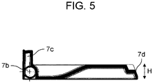
- FIG. 4 is a perspective view of holding member 7, and FIG. 5 is a cross-sectional view taken along line A-A in FIG. 4 , which is a central portion of holding member 7.
- Holding member 7 includes: rotational shaft unit 7b that engages with the rotational supporting unit and is able to rotate about horizontal shaft 7a; rotation stopping unit 7c that is able to stop rotational operation when holding member 7 rotates by 90 degrees with respect to main body casing 1; and contact surface 7d that is brought into contact with the indoor wall surface or mounting plate 6 when the wall-mounted air conditioner is held in an inclined manner with respect to the wall. Further, as illustrated in FIG.
- holding member 7 is able to secure height H so as to increase a contact area of contact surface 7d with the indoor wall surface or mounting plate 6, and is able to maintain the rigidity of holding member 7 high even if holding member 7 has a thin shape by providing a substantial box shape.
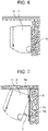
- FIG. 6 is a side view of the wall-mounted air conditioner installed on the wall
- FIG. 7 is a side view of the wall-mounted air conditioner where piping work and arrangement work are carried out during installation, that is, a state in which the wall-mounted air conditioner is supported by holding member 7 and is maintained in an inclined state.
- a worker fixes mounting plate 6 to the wall with screws at several points.
- the worker hooks attachment claw 1a of main body casing 1 on locking unit 6a of mounting plate 6 while causing front frame 2 not to be brought into contact with ceiling 11.
- the worker rotates holding member 7 contained in the holding member containing unit 1b of main body casing 1 by 90 degrees with the worker's hand, and causes holding member 7 to protrude from main body casing 1.
- the wall-mounted air conditioner can be inclined and maintain its posture.
- the worker secures a space between the wall-mounted air conditioner and wall 10 in this inclined state, and carries out various works for connecting refrigerant pipes of the indoor unit and the outdoor unit, arranging a drain hose, connecting the indoor unit and the outdoor unit electrically, and the like.
- the worker rotates holding member 7 upward by 90 degrees, and stores holding member 7 in the holding member containing unit 1b of main body casing 1.
- the worker further fixes the back surface of main body casing 1 and mounting plate 6 with claws, screws, or the like such that the back surface of main body casing 1 and mounting plate 6 are fitted to each other at their lower portions.
- the worker confirms that main body casing 1 and mounting plate 6 are reliably fitted.
- the wall-mounted air conditioner is installed on wall 10.
- the wall-mounted air conditioner includes: main body casing 1 including first and second side end portions disposed respectively on opposite sides to each other in a horizontal direction, and a central portion disposed between the first and second side end portions; heat exchanger 3 disposed in the central portion of main body casing 1; fan motor 4 disposed in the first side end portion of main body casing 1; mounting plate 6 having locking unit 6a for locking main body casing 1, the locking unit 6a being disposed at an upper portion of the mounting plate; and holding member 7 configured to hold main body casing 1 in an inclined state where main body casing 1 is locked to the locking unit 6a during installation, wherein main body casing 1 includes holding member containing unit 1b configured to contain holding member 7, and a rotational supporting unit having a horizontal shaft engaged with holding member 7, and holding member 7 is disposed in a position, the position being in the second side end portion of main body casing 1 and on a side of a back surface of main body casing 1, the holding member 7 includes rotational shaft unit using the horizontal
- holding member 7 is positioned opposite to fan motor 4 across heat exchanger 3 in front view.
- the wall-mounted air conditioner is able to effectively use a storage space in a depth direction of the electric part 5 and may increase an effective length of heat exchanger 3 in the horizontal direction.
- the wall-mounted air conditioner may employ heat exchanger 3 having a large cross-sectional area.
- holding member 7 is disposed so as not to overlap heat exchanger 3 in front view, it is possible, regardless of the cross section of heat exchanger 3, to secure a storage space of holding member 7 and to provide a shape necessary for holding main body casing 1 in an inclined state.
- holding member 7 rotates upward, to a direction that does not relate to the space in which the pipe is disposed, and is stored in main body casing 1.
- the worker is able to carry out the piping work easily. Therefore, it is possible to reduce the depth size of the indoor unit, improve the energy saving performance, and improve the workability during installation of the indoor unit.
- holding member 7 may have a substantial box shape including contact surface 7d that is brought into contact with the indoor wall surface or mounting plate 6.
- holding member 7 Since holding member 7 has a substantial box shape, sufficient strength and rigidity may be secured even if holding member 7 is a resin molded article. Furthermore, by increasing height H of holding member 7, holding member 7 may increase the area of contact surface 7d in contact with the indoor wall surface or mounting plate 6 attached to the indoor wall surface. Therefore, even if holding member 7 is not at the position of the center of gravity of the wall-mounted air conditioner in a state where the wall-mounted air conditioner is held in an inclined manner, holding member 7 can be firmly supported with respect to the indoor wall surface, and the posture of the wall-mounted air conditioner can be stably maintained. Therefore, it is possible to maintain and improve workability. Further, in a case where holding member 7 is brought into direct contact with the indoor wall surface, it is not necessary to provide mounting plate 6 at a position where holding member 7 is disposed. Therefore, the material for mounting plate 6 can be reduced, and the cost can be reduced.
- holding member 7 may include: rotation stopping unit 7c that is able to stop the rotational operation when holding member 7 is rotated by 90 degrees about rotational shaft unit 7b; and a rotation stopping unit locking unit that locks rotation stopping unit 7c to one or both of holding member 7 and main body casing 1.
- holding member 7 can be configured to have an optimum length without securing a length more than necessary. Further, when holding member 7 is rotated until rotation stopping unit 7c is brought into contact with holding member containing unit 1b of main body casing 1, holding member 7 is rotated by 90 degrees. At this time, rotation stopping unit 7c can be locked by the rotation stopping unit locking unit such as a claw. Therefore, it is possible to suppress the occurrence of a situation in which main body casing 1 cannot be maintained in the inclined state due to unintentional rotation of holding member 7 during pipe arrangement work, and the worker is able to carry out the work safely.
- holding member 7 may be disposed at a position adjacent to the side surface of main body casing 1.
- holding member 7 can be disposed at a distance at which the worker is able to hold holding member 7 with hand from the side surface. Therefore, the worker is able to easily move holding member 7, and it is possible to improve the workability.
- a second exemplary embodiment will be described below with reference to FIGS. 8 to 10 .
- a wall-mounted air conditioner according to the second exemplary embodiment includes front frame 2 and construction cover 15 disposed on a lower surface portion of front frame 2.
- construction cover 15 also serves as a design surface of the wall-mounted air conditioner, and is configured separately from front frame 2.
- FIG. 8 is a perspective view, as viewed slightly upward in front, of the wall-mounted air conditioner according to the second exemplary embodiment of the present disclosure.
- Construction cover 15 is disposed below main body casing 1.
- construction cover 15 includes screw covers 16, one on a left side and one on a right side. The worker is able to remove screw covers 16 to remove screws for fixing construction cover 15 to main body casing 1. After removing the screws, the worker is able to remove construction cover 15 by removing the claws locked to main body casing 1 and front frame 2.
- FIG. 9 is a perspective view, as viewed slightly upward in front, of the wall-mounted air conditioner from which construction cover 15 is removed. At this time, an area surrounded by a dotted line serves as work space 20 for piping arrangement.
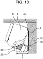
- FIG. 10 is a side view of the wall-mounted air conditioner according to the second exemplary embodiment during installation, where holding member 7 holds main body casing 1 in the inclined state with respect to the indoor wall surface.
- FIG. 10 illustrates a partial cross-sectional view such that pipe storage space 30 can be seen. It is possible to secure wide work space 20 by removing construction cover 15.
- the wall-mounted air conditioner includes: pipe storage space 30 in the lower portion of main body casing 1, pipe storage space 30 being for the indoor-outdoor connection pipes that connects the indoor unit and the outdoor unit; and detachable construction cover 15 that covers the indoor-outdoor connection pipes disposed in pipe storage space 30.
- the first exemplary embodiment and the second exemplary embodiment have been described as examples of the present disclosure.
- the techniques of the present disclosure are not limited to those examples, and can also be applied to exemplary embodiments in which changes, replacements, additions, omissions, and the like are made.
- a new exemplary embodiment may be made by combining the components described in the first and second exemplary embodiments.
- the first and second exemplary embodiments describe the example of the wall-mounted air conditioner in which in front view, fan motor 4 and electric part 5 are provided on the right side (first side end portion) and holding member 7 is provided on the left side (second side end portion) with heat exchanger 3 interposed therebetween.
- the wall-mounted air conditioner may be any type as long as it can be installed on the wall and perform air-conditioning. Therefore, the wall-mounted air conditioner is not limited to the wall-mounted air conditioner including fan motor 4 and electric part 5 on the right side and holding member 7 on the left side with heat exchanger 3 interposed therebetween in front view.
- the area of the heat-transfer portion of the heat exchanger can be increased regardless of holding member 7, and thus, it is possible to reduce the depth size of the indoor unit, improve the energy saving performance, and improve the workability during installation of the indoor unit.
- the present disclosure is applicable to an indoor unit of an air conditioner having a reduced depth size and high energy saving performance. Specifically, the present disclosure is applicable to wall-mounted air conditioner or the like.
Landscapes
- Engineering & Computer Science (AREA)
- Chemical & Material Sciences (AREA)
- Combustion & Propulsion (AREA)
- Mechanical Engineering (AREA)
- General Engineering & Computer Science (AREA)
- Air Filters, Heat-Exchange Apparatuses, And Housings Of Air-Conditioning Units (AREA)
Applications Claiming Priority (1)
| Application Number | Priority Date | Filing Date | Title |
|---|---|---|---|
| JP2021017017A JP7607191B2 (ja) | 2021-02-05 | 2021-02-05 | 壁掛型空気調和機 |
Publications (2)
| Publication Number | Publication Date |
|---|---|
| EP4040054A1 true EP4040054A1 (fr) | 2022-08-10 |
| EP4040054B1 EP4040054B1 (fr) | 2025-01-01 |
Family
ID=78332565
Family Applications (1)
| Application Number | Title | Priority Date | Filing Date |
|---|---|---|---|
| EP21203586.9A Active EP4040054B1 (fr) | 2021-02-05 | 2021-10-20 | Climatiseur à montage mural |
Country Status (3)
| Country | Link |
|---|---|
| EP (1) | EP4040054B1 (fr) |
| JP (1) | JP7607191B2 (fr) |
| CN (1) | CN114857672A (fr) |
Cited By (3)
| Publication number | Priority date | Publication date | Assignee | Title |
|---|---|---|---|---|
| TWI855626B (zh) * | 2023-04-06 | 2024-09-11 | 台灣松下電器股份有限公司 | 空調設備 |
| TWI855627B (zh) * | 2023-04-06 | 2024-09-11 | 台灣松下電器股份有限公司 | 空調設備 |
| EP4549825A1 (fr) * | 2023-11-02 | 2025-05-07 | Panasonic Intellectual Property Management Co., Ltd. | Climatiseur |
Citations (6)
| Publication number | Priority date | Publication date | Assignee | Title |
|---|---|---|---|---|
| JPH06221610A (ja) * | 1993-01-28 | 1994-08-12 | Sanyo Electric Co Ltd | 空気調和機 |
| JPH06241493A (ja) * | 1993-02-19 | 1994-08-30 | Nhk Spring Co Ltd | 空気調和機の据付装置 |
| JP2002098403A (ja) | 2000-09-22 | 2002-04-05 | Sanyo Electric Co Ltd | 空気調和機の据付装置 |
| JP2006145049A (ja) | 2004-11-16 | 2006-06-08 | Sanyo Electric Co Ltd | 空気調和装置 |
| US20110048050A1 (en) * | 2009-08-27 | 2011-03-03 | Sanyo Electric Co., Ltd. | Wall-hung air conditioner and installing device for air conditioner |
| WO2016154952A1 (fr) * | 2015-03-31 | 2016-10-06 | 广东美的制冷设备有限公司 | Unité de climatisation intérieure |
Family Cites Families (9)
| Publication number | Priority date | Publication date | Assignee | Title |
|---|---|---|---|---|
| JP2854219B2 (ja) * | 1993-07-30 | 1999-02-03 | 三洋電機株式会社 | 空気調和機 |
| JPH0718154U (ja) * | 1993-09-03 | 1995-03-31 | 株式会社富士通ゼネラル | 空気調和機の据付装置 |
| JP2004347232A (ja) | 2003-05-22 | 2004-12-09 | Hitachi Home & Life Solutions Inc | 空気調和機 |
| JP4698747B2 (ja) * | 2009-08-19 | 2011-06-08 | シャープ株式会社 | 壁掛け形空気調和機 |
| JP5359771B2 (ja) | 2009-09-25 | 2013-12-04 | 三洋電機株式会社 | 分離型空気調和機の室内ユニットの据付装置 |
| JP4700127B2 (ja) * | 2009-09-14 | 2011-06-15 | シャープ株式会社 | 空気調和機の室内機 |
| JP5880585B2 (ja) * | 2014-01-27 | 2016-03-09 | ダイキン工業株式会社 | 室外機 |
| CN208418988U (zh) | 2018-06-26 | 2019-01-22 | 青岛海尔空调器有限总公司 | 空调室内机及空调器 |
| JP7004836B2 (ja) * | 2018-09-18 | 2022-01-21 | 三菱電機株式会社 | 冷凍サイクル装置 |
-
2021
- 2021-02-05 JP JP2021017017A patent/JP7607191B2/ja active Active
- 2021-08-17 CN CN202110943840.1A patent/CN114857672A/zh active Pending
- 2021-10-20 EP EP21203586.9A patent/EP4040054B1/fr active Active
Patent Citations (6)
| Publication number | Priority date | Publication date | Assignee | Title |
|---|---|---|---|---|
| JPH06221610A (ja) * | 1993-01-28 | 1994-08-12 | Sanyo Electric Co Ltd | 空気調和機 |
| JPH06241493A (ja) * | 1993-02-19 | 1994-08-30 | Nhk Spring Co Ltd | 空気調和機の据付装置 |
| JP2002098403A (ja) | 2000-09-22 | 2002-04-05 | Sanyo Electric Co Ltd | 空気調和機の据付装置 |
| JP2006145049A (ja) | 2004-11-16 | 2006-06-08 | Sanyo Electric Co Ltd | 空気調和装置 |
| US20110048050A1 (en) * | 2009-08-27 | 2011-03-03 | Sanyo Electric Co., Ltd. | Wall-hung air conditioner and installing device for air conditioner |
| WO2016154952A1 (fr) * | 2015-03-31 | 2016-10-06 | 广东美的制冷设备有限公司 | Unité de climatisation intérieure |
Cited By (3)
| Publication number | Priority date | Publication date | Assignee | Title |
|---|---|---|---|---|
| TWI855626B (zh) * | 2023-04-06 | 2024-09-11 | 台灣松下電器股份有限公司 | 空調設備 |
| TWI855627B (zh) * | 2023-04-06 | 2024-09-11 | 台灣松下電器股份有限公司 | 空調設備 |
| EP4549825A1 (fr) * | 2023-11-02 | 2025-05-07 | Panasonic Intellectual Property Management Co., Ltd. | Climatiseur |
Also Published As
| Publication number | Publication date |
|---|---|
| JP2022120242A (ja) | 2022-08-18 |
| EP4040054B1 (fr) | 2025-01-01 |
| JP7607191B2 (ja) | 2024-12-27 |
| CN114857672A (zh) | 2022-08-05 |
Similar Documents
| Publication | Publication Date | Title |
|---|---|---|
| EP4040054B1 (fr) | Climatiseur à montage mural | |
| JP5950877B2 (ja) | 空気調和機の化粧パネル取付構造及び室内機 | |
| US20080188175A1 (en) | Air circulator with releasable air grille | |
| EP2520869B1 (fr) | Climatiseur monté au plafond | |
| WO2019202757A1 (fr) | Climatiseur extérieur et système de ventilation | |
| JP5272351B2 (ja) | 設備機器 | |
| EP4102143B1 (fr) | Dispositif de source de chaleur de pompe à chaleur | |
| EP3441693B1 (fr) | Climatiseur | |
| JP3806536B2 (ja) | ビルトイン型空気調和機 | |
| CN107449060B (zh) | 窗式空调器 | |
| CN101270898B (zh) | 吸顶式空调机 | |
| JP4523822B2 (ja) | 天井埋込み形空気調和機 | |
| CN215570826U (zh) | 一种室内空调器及电器盒 | |
| JP4845557B2 (ja) | 天井カセット形空気調和機 | |
| CN101581480A (zh) | 空调器的室内机 | |
| JP4922643B2 (ja) | 天井カセット形空気調和機 | |
| JPH0330731Y2 (fr) | ||
| JP4245443B2 (ja) | 空気調和機 | |
| CA2578329A1 (fr) | Dispositif de circulation d'air muni d'un event amovible | |
| JPH03241891A (ja) | 電装箱の取付装置 | |
| CN203785087U (zh) | 内装型空气调节器 | |
| JP2025076754A (ja) | 空気調和機 | |
| JP2005083703A (ja) | 空気調和機 | |
| JPH0737059Y2 (ja) | 空気調和装置の送風機取付構造 | |
| JPH11351661A (ja) | ファンユニットの吊下装置 |
Legal Events
| Date | Code | Title | Description |
|---|---|---|---|
| PUAI | Public reference made under article 153(3) epc to a published international application that has entered the european phase |
Free format text: ORIGINAL CODE: 0009012 |
|
| STAA | Information on the status of an ep patent application or granted ep patent |
Free format text: STATUS: THE APPLICATION HAS BEEN PUBLISHED |
|
| AK | Designated contracting states |
Kind code of ref document: A1 Designated state(s): AL AT BE BG CH CY CZ DE DK EE ES FI FR GB GR HR HU IE IS IT LI LT LU LV MC MK MT NL NO PL PT RO RS SE SI SK SM TR |
|
| STAA | Information on the status of an ep patent application or granted ep patent |
Free format text: STATUS: REQUEST FOR EXAMINATION WAS MADE |
|
| 17P | Request for examination filed |
Effective date: 20230210 |
|
| RBV | Designated contracting states (corrected) |
Designated state(s): AL AT BE BG CH CY CZ DE DK EE ES FI FR GB GR HR HU IE IS IT LI LT LU LV MC MK MT NL NO PL PT RO RS SE SI SK SM TR |
|
| GRAP | Despatch of communication of intention to grant a patent |
Free format text: ORIGINAL CODE: EPIDOSNIGR1 |
|
| STAA | Information on the status of an ep patent application or granted ep patent |
Free format text: STATUS: GRANT OF PATENT IS INTENDED |
|
| INTG | Intention to grant announced |
Effective date: 20240724 |
|
| GRAS | Grant fee paid |
Free format text: ORIGINAL CODE: EPIDOSNIGR3 |
|
| GRAA | (expected) grant |
Free format text: ORIGINAL CODE: 0009210 |
|
| STAA | Information on the status of an ep patent application or granted ep patent |
Free format text: STATUS: THE PATENT HAS BEEN GRANTED |
|
| AK | Designated contracting states |
Kind code of ref document: B1 Designated state(s): AL AT BE BG CH CY CZ DE DK EE ES FI FR GB GR HR HU IE IS IT LI LT LU LV MC MK MT NL NO PL PT RO RS SE SI SK SM TR |
|
| REG | Reference to a national code |
Ref country code: GB Ref legal event code: FG4D |
|
| REG | Reference to a national code |
Ref country code: CH Ref legal event code: EP |
|
| REG | Reference to a national code |
Ref country code: DE Ref legal event code: R096 Ref document number: 602021024154 Country of ref document: DE |
|
| REG | Reference to a national code |
Ref country code: IE Ref legal event code: FG4D |
|
| REG | Reference to a national code |
Ref country code: LT Ref legal event code: MG9D |
|
| REG | Reference to a national code |
Ref country code: NL Ref legal event code: MP Effective date: 20250101 |
|
| REG | Reference to a national code |
Ref country code: AT Ref legal event code: MK05 Ref document number: 1756594 Country of ref document: AT Kind code of ref document: T Effective date: 20250101 |
|
| PG25 | Lapsed in a contracting state [announced via postgrant information from national office to epo] |
Ref country code: NL Free format text: LAPSE BECAUSE OF FAILURE TO SUBMIT A TRANSLATION OF THE DESCRIPTION OR TO PAY THE FEE WITHIN THE PRESCRIBED TIME-LIMIT Effective date: 20250101 |
|
| PG25 | Lapsed in a contracting state [announced via postgrant information from national office to epo] |
Ref country code: FI Free format text: LAPSE BECAUSE OF FAILURE TO SUBMIT A TRANSLATION OF THE DESCRIPTION OR TO PAY THE FEE WITHIN THE PRESCRIBED TIME-LIMIT Effective date: 20250101 |
|
| PG25 | Lapsed in a contracting state [announced via postgrant information from national office to epo] |
Ref country code: PL Free format text: LAPSE BECAUSE OF FAILURE TO SUBMIT A TRANSLATION OF THE DESCRIPTION OR TO PAY THE FEE WITHIN THE PRESCRIBED TIME-LIMIT Effective date: 20250101 |
|
| PG25 | Lapsed in a contracting state [announced via postgrant information from national office to epo] |
Ref country code: ES Free format text: LAPSE BECAUSE OF FAILURE TO SUBMIT A TRANSLATION OF THE DESCRIPTION OR TO PAY THE FEE WITHIN THE PRESCRIBED TIME-LIMIT Effective date: 20250101 |
|
| PG25 | Lapsed in a contracting state [announced via postgrant information from national office to epo] |
Ref country code: NO Free format text: LAPSE BECAUSE OF FAILURE TO SUBMIT A TRANSLATION OF THE DESCRIPTION OR TO PAY THE FEE WITHIN THE PRESCRIBED TIME-LIMIT Effective date: 20250401 Ref country code: IS Free format text: LAPSE BECAUSE OF FAILURE TO SUBMIT A TRANSLATION OF THE DESCRIPTION OR TO PAY THE FEE WITHIN THE PRESCRIBED TIME-LIMIT Effective date: 20250501 |
|
| PG25 | Lapsed in a contracting state [announced via postgrant information from national office to epo] |
Ref country code: HR Free format text: LAPSE BECAUSE OF FAILURE TO SUBMIT A TRANSLATION OF THE DESCRIPTION OR TO PAY THE FEE WITHIN THE PRESCRIBED TIME-LIMIT Effective date: 20250101 |
|
| PG25 | Lapsed in a contracting state [announced via postgrant information from national office to epo] |
Ref country code: PT Free format text: LAPSE BECAUSE OF FAILURE TO SUBMIT A TRANSLATION OF THE DESCRIPTION OR TO PAY THE FEE WITHIN THE PRESCRIBED TIME-LIMIT Effective date: 20250502 Ref country code: LV Free format text: LAPSE BECAUSE OF FAILURE TO SUBMIT A TRANSLATION OF THE DESCRIPTION OR TO PAY THE FEE WITHIN THE PRESCRIBED TIME-LIMIT Effective date: 20250101 |
|
| PG25 | Lapsed in a contracting state [announced via postgrant information from national office to epo] |
Ref country code: GR Free format text: LAPSE BECAUSE OF FAILURE TO SUBMIT A TRANSLATION OF THE DESCRIPTION OR TO PAY THE FEE WITHIN THE PRESCRIBED TIME-LIMIT Effective date: 20250402 Ref country code: BG Free format text: LAPSE BECAUSE OF FAILURE TO SUBMIT A TRANSLATION OF THE DESCRIPTION OR TO PAY THE FEE WITHIN THE PRESCRIBED TIME-LIMIT Effective date: 20250101 |
|
| PG25 | Lapsed in a contracting state [announced via postgrant information from national office to epo] |
Ref country code: AT Free format text: LAPSE BECAUSE OF FAILURE TO SUBMIT A TRANSLATION OF THE DESCRIPTION OR TO PAY THE FEE WITHIN THE PRESCRIBED TIME-LIMIT Effective date: 20250101 |
|
| PG25 | Lapsed in a contracting state [announced via postgrant information from national office to epo] |
Ref country code: CZ Free format text: LAPSE BECAUSE OF FAILURE TO SUBMIT A TRANSLATION OF THE DESCRIPTION OR TO PAY THE FEE WITHIN THE PRESCRIBED TIME-LIMIT Effective date: 20250101 |
|
| PG25 | Lapsed in a contracting state [announced via postgrant information from national office to epo] |
Ref country code: SE Free format text: LAPSE BECAUSE OF FAILURE TO SUBMIT A TRANSLATION OF THE DESCRIPTION OR TO PAY THE FEE WITHIN THE PRESCRIBED TIME-LIMIT Effective date: 20250101 |
|
| REG | Reference to a national code |
Ref country code: DE Ref legal event code: R097 Ref document number: 602021024154 Country of ref document: DE |
|
| PG25 | Lapsed in a contracting state [announced via postgrant information from national office to epo] |
Ref country code: SM Free format text: LAPSE BECAUSE OF FAILURE TO SUBMIT A TRANSLATION OF THE DESCRIPTION OR TO PAY THE FEE WITHIN THE PRESCRIBED TIME-LIMIT Effective date: 20250101 |
|
| PG25 | Lapsed in a contracting state [announced via postgrant information from national office to epo] |
Ref country code: DK Free format text: LAPSE BECAUSE OF FAILURE TO SUBMIT A TRANSLATION OF THE DESCRIPTION OR TO PAY THE FEE WITHIN THE PRESCRIBED TIME-LIMIT Effective date: 20250101 |
|
| PG25 | Lapsed in a contracting state [announced via postgrant information from national office to epo] |
Ref country code: IT Free format text: LAPSE BECAUSE OF FAILURE TO SUBMIT A TRANSLATION OF THE DESCRIPTION OR TO PAY THE FEE WITHIN THE PRESCRIBED TIME-LIMIT Effective date: 20250101 |
|
| PG25 | Lapsed in a contracting state [announced via postgrant information from national office to epo] |
Ref country code: EE Free format text: LAPSE BECAUSE OF FAILURE TO SUBMIT A TRANSLATION OF THE DESCRIPTION OR TO PAY THE FEE WITHIN THE PRESCRIBED TIME-LIMIT Effective date: 20250101 |
|
| PG25 | Lapsed in a contracting state [announced via postgrant information from national office to epo] |
Ref country code: RO Free format text: LAPSE BECAUSE OF FAILURE TO SUBMIT A TRANSLATION OF THE DESCRIPTION OR TO PAY THE FEE WITHIN THE PRESCRIBED TIME-LIMIT Effective date: 20250101 |
|
| PG25 | Lapsed in a contracting state [announced via postgrant information from national office to epo] |
Ref country code: SK Free format text: LAPSE BECAUSE OF FAILURE TO SUBMIT A TRANSLATION OF THE DESCRIPTION OR TO PAY THE FEE WITHIN THE PRESCRIBED TIME-LIMIT Effective date: 20250101 |
|
| PLBE | No opposition filed within time limit |
Free format text: ORIGINAL CODE: 0009261 |
|
| STAA | Information on the status of an ep patent application or granted ep patent |
Free format text: STATUS: NO OPPOSITION FILED WITHIN TIME LIMIT |
|
| 26N | No opposition filed |
Effective date: 20251002 |
|
| PGFP | Annual fee paid to national office [announced via postgrant information from national office to epo] |
Ref country code: DE Payment date: 20251021 Year of fee payment: 5 |