EP4549825A1 - Climatiseur - Google Patents
Climatiseur Download PDFInfo
- Publication number
- EP4549825A1 EP4549825A1 EP24208845.8A EP24208845A EP4549825A1 EP 4549825 A1 EP4549825 A1 EP 4549825A1 EP 24208845 A EP24208845 A EP 24208845A EP 4549825 A1 EP4549825 A1 EP 4549825A1
- Authority
- EP
- European Patent Office
- Prior art keywords
- openable member
- housing
- indoor
- air conditioner
- indoor unit
- Prior art date
- Legal status (The legal status is an assumption and is not a legal conclusion. Google has not performed a legal analysis and makes no representation as to the accuracy of the status listed.)
- Pending
Links
Images




Classifications
-
- F—MECHANICAL ENGINEERING; LIGHTING; HEATING; WEAPONS; BLASTING
- F24—HEATING; RANGES; VENTILATING
- F24F—AIR-CONDITIONING; AIR-HUMIDIFICATION; VENTILATION; USE OF AIR CURRENTS FOR SCREENING
- F24F13/00—Details common to, or for air-conditioning, air-humidification, ventilation or use of air currents for screening
- F24F13/20—Casings or covers
-
- F—MECHANICAL ENGINEERING; LIGHTING; HEATING; WEAPONS; BLASTING
- F24—HEATING; RANGES; VENTILATING
- F24F—AIR-CONDITIONING; AIR-HUMIDIFICATION; VENTILATION; USE OF AIR CURRENTS FOR SCREENING
- F24F1/00—Room units for air-conditioning, e.g. separate or self-contained units or units receiving primary air from a central station
- F24F1/0007—Indoor units, e.g. fan coil units
- F24F1/0068—Indoor units, e.g. fan coil units characterised by the arrangement of refrigerant piping outside the heat exchanger within the unit casing
-
- F—MECHANICAL ENGINEERING; LIGHTING; HEATING; WEAPONS; BLASTING
- F24—HEATING; RANGES; VENTILATING
- F24F—AIR-CONDITIONING; AIR-HUMIDIFICATION; VENTILATION; USE OF AIR CURRENTS FOR SCREENING
- F24F1/00—Room units for air-conditioning, e.g. separate or self-contained units or units receiving primary air from a central station
- F24F1/0007—Indoor units, e.g. fan coil units
- F24F1/0043—Indoor units, e.g. fan coil units characterised by mounting arrangements
- F24F1/0057—Indoor units, e.g. fan coil units characterised by mounting arrangements mounted in or on a wall
-
- F—MECHANICAL ENGINEERING; LIGHTING; HEATING; WEAPONS; BLASTING
- F24—HEATING; RANGES; VENTILATING
- F24F—AIR-CONDITIONING; AIR-HUMIDIFICATION; VENTILATION; USE OF AIR CURRENTS FOR SCREENING
- F24F1/00—Room units for air-conditioning, e.g. separate or self-contained units or units receiving primary air from a central station
- F24F1/06—Separate outdoor units, e.g. outdoor unit to be linked to a separate room comprising a compressor and a heat exchanger
- F24F1/26—Refrigerant piping
- F24F1/32—Refrigerant piping for connecting the separate outdoor units to indoor units
-
- F—MECHANICAL ENGINEERING; LIGHTING; HEATING; WEAPONS; BLASTING
- F24—HEATING; RANGES; VENTILATING
- F24F—AIR-CONDITIONING; AIR-HUMIDIFICATION; VENTILATION; USE OF AIR CURRENTS FOR SCREENING
- F24F1/00—Room units for air-conditioning, e.g. separate or self-contained units or units receiving primary air from a central station
- F24F1/06—Separate outdoor units, e.g. outdoor unit to be linked to a separate room comprising a compressor and a heat exchanger
- F24F1/26—Refrigerant piping
- F24F1/34—Protection means thereof, e.g. covers for refrigerant pipes
Definitions
- the present disclosure relates to an air conditioner.
- PTL 1 discloses an installation apparatus for an air conditioner, the installation apparatus facilitating connection work of refrigerant pipes.
- the installation apparatus for an air conditioner includes an opening formed in a bottom surface of a body and a cover configured to cover the opening.
- the present disclosure provides an air conditioner that facilitates connection between an indoor-side pipe of an indoor unit and an inner-outer connection pipe while suppressing rattling of the indoor unit after installation.
- the air conditioner according to the present disclosure includes an indoor unit of a wall-mounted type attached to a wall surface with an installation plate interposed therebetween.
- the indoor unit includes a housing that houses an indoor heat exchanger, an indoor-side pipe that is drawn out from a back surface of the housing to the outside, a connection pipe housing that is formed on the back surface and is capable of housing the indoor-side pipe, and an openable member that is provided below the connection pipe housing to be opened and closed by being rotated.
- the openable member includes a fixing claw, and is capable of not only holding the fixing claw in a state locked to the installation plate in a closed state, but also exposing the connection pipe housing downward when brought into an open state.
- the air conditioner according to the present disclosure is capable of facilitating connection between the indoor-side pipe of the indoor unit and the inner-outer connection pipe while suppressing rattling of the indoor unit after installation.
- the present disclosure provides an air conditioner that facilitates connection between an indoor-side pipe of an indoor unit and an inner-outer connection pipe while suppressing rattling of the indoor unit after installation.
- Fig. 1 is a perspective view of indoor unit 1 of an air conditioner according to the first exemplary embodiment, and illustrates indoor unit 1 as viewed from the front.
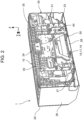
- Fig. 2 is a perspective view of indoor unit 1, and illustrates indoor unit 1 as viewed from the rear.
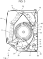
- Fig. 3 is a sectional view of indoor unit 1, and illustrates indoor unit 1 in a section perpendicular to a left-right direction.
- the drawings each show reference sign X indicating a right direction of indoor unit 1, reference sign Y indicating a front direction of indoor unit 1, and reference sign Z indicating an upper direction of indoor unit 1.
- Directions such as up and down, left and right, and front and back in the following description refer to directions with respect to indoor unit 1 unless otherwise specified.
- the air conditioner according to the first exemplary embodiment includes indoor unit 1 and an outdoor unit (not illustrated).
- Indoor unit 1 is a so-called wall-mounted indoor unit attached to wall surface W in a room.
- Indoor unit 1 includes housing 10 in the shape of a box elongated in the left-right direction. Housing 10 internally houses indoor heat exchanger 11, blower 13, and the like (see Fig. 3 ).
- housing 10 includes decorative cover 20 and base frame 30.
- Decorative cover 20 is a resin member covering indoor heat exchanger 11 and blower 13 laterally, vertically, and from the front.
- Decorative cover 20 is open backward, or open behind.
- decorative cover 20 includes front panel 22 constituting a front surface of housing 10, upper panel 24 constituting an upper surface of housing 10 and allowing ventilation, a pair of side panels 26 constituting left and right side surfaces of housing 10, and lower bar 28 constituting a lower surface of housing 10.
- Each of members 22, 24, 26, 28 constituting decorative cover 20 is individually detachable.
- Decorative cover 20 is provided near its front surface with air outlet 21 communicating inside and outside decorative cover 20.
- Air outlet 21 is an opening formed substantially entirely in the left-right direction of decorative cover 20.
- Indoor unit 1 blows air having exchanged heat with a refrigerant in indoor heat exchanger 11 into the room from air outlet 21 to perform air conditioning in the room.
- Air outlet 21 is provided with flap 23 that adjusts a wind direction.
- base frame 30 is a resin member that closes an opening behind decorative cover 20.
- Base frame 30 includes back surface part 31 constituting a back surface of housing 10.
- auxiliary pipe 15 is drawn out of housing 10 from an upper right part of back surface part 31.
- Auxiliary pipe 15 is obtained by bundling indoor-side liquid pipe 17 and indoor-side gas pipe 19 connected to indoor heat exchanger 11.
- Indoor-side liquid pipe 17 and indoor-side gas pipe 19 of auxiliary pipe 15 are connected to a refrigerant pipe of the outdoor unit through inner-outer connection pipes P1, P2, respectively (see Fig. 6 ).
- inner-outer connection pipes P1, P2, respectively see Fig. 6
- Indoor-side liquid pipe 17 and indoor-side gas pipe 19 in the present exemplary embodiment correspond to the "indoor-side pipe" of the present disclosure.
- Back surface part 31 includes a lower part provided with connection pipe housing 33 recessed forward substantially entirely in the left-right direction.
- Connection pipe housing 33 houses auxiliary pipe 15 and inner-outer connection pipes P1, P2 when auxiliary pipe 15 drawn from the upper right part of back surface part 31 is routed leftward.
- Indoor-side pipes 17, 19 and inner-outer connection pipes P1, P2 are routed in connection pipe housing 33 leftward when a hole formed in wall surface W to allow passing of inner-outer connection pipes P1, P2 is located left from an installation position of indoor unit 1, for example.
- Base frame 30 includes upper fixing claw 35.
- Upper fixing claw 35 is a protrusion formed downward from an upper end of base frame 30.
- Upper fixing claw 35 is hooked from above to an upper edge of installation plate 40 fixed to wall surface W.
- installation plate 40 is a plate-like member made of a sheet metal.
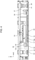
- Fig. 4 is a bottom view of indoor unit 1, and illustrates a state in which decorative cover 20 is removed from indoor unit 1 attached to installation plate 40.
- Base frame 30 is provided at its lower end with lower fixing part 37.
- Lower fixing part 37 is a horizontal flat plate-like structure extending rearward from the lower end of base frame 30.
- Lower fixing part 37 is located below connection pipe housing 33.
- connection pipe housing 33 When indoor-side pipes 17, 19 are housed in connection pipe housing 33, lower fixing part 37 is located below indoor-side pipes 17, 19 as illustrated in Fig. 4 .
- one lower fixing part 37 is formed on base frame 30.
- lower fixing part 37 is located below upper fixing claw 35 at the right.
- Lower fixing part 37 is provided with lower fixing claw 38 and elongated hole 39.
- Lower fixing claw 38 is a protrusion protruding downward from a rear end of lower fixing part 37.
- lower fixing claw 38 is hooked on first hook portion 41 of installation plate 40 from above.
- First hook part 41 is formed by bending a lower end of installation plate 40 forward.
- First hook part 41 is provided at its center with an opening.
- Lower fixing claw 38 is inserted into the opening of first hook part 41 from above to be hooked by first hook part 41.
- Elongated hole 39 passes through lower fixing part 37 and is long in the left-right direction.
- Lower fixing part 37 is fastened to installation plate 40 by a screw (not illustrated) or the like inserted into elongated hole 39.
- openable member 50 is provided below connection pipe housing 33. That is, openable member 50 is located below indoor-side pipe 17 housed in connection pipe housing 33. In the present exemplary embodiment, openable member 50 is located below distal end 17a of indoor-side liquid pipe 17.
- Openable member 50 is made of resin. Openable member 50 is provided at a position substantially symmetrical to lower fixing part 37 with respect to the center of indoor unit 1 in the left-right direction. That is, openable member 50 is located below upper fixing claw 35 at the left.
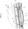
- Fig. 5 is a perspective view of openable member 50, and illustrates openable member 50 in a closed state.
- Fig. 6 is a perspective view of openable member 50, and illustrates openable member 50 in an open state.
- openable member 50 is attached to base frame 30 in a rotatable manner about an axis of rotation in the left-right direction.
- Openable member 50 is rotated to be brought into the closed state to cover a part of connection pipe housing 33 from below, the part being provided with distal end 17a of indoor-side liquid pipe 17.
- Openable member 50 is configured to enable distal end 17a to be exposed downward when being rotated to be brought into the open state.
- a direction around the axis of rotation of openable member 50 is referred to as a circumferential direction
- a direction orthogonal to the circumferential direction is referred to as a radial direction.
- openable member 50 includes main body 51 in the shape of a substantially flat plate.
- Main body 51 is provided substantially along the radial direction.
- Main body 51 is provided with a plurality of ribs for reinforcement.
- Main body 51 is provided at its opposite ends in the left-right direction with respective mountain-shaped protrusions 52 protruding outward in the left-right direction.
- Mountain-shaped protrusions 52 each have a substantially triangular shape in section. Mountain-shaped protrusions 52 are fitted into respective mountain-shaped recesses 36 formed in base frame 30 and recessed outward in the left-right direction.
- openable member 50 is held in the closed state.
- main body 51 is in an attitude (i.e., attitudes in Figs. 3 , 4 , and 5 ) extending substantially horizontally backward on the axis of rotation.
- main body 51 is provided at its radially outer end with openable member fixing claw 53.
- Openable member fixing claw 53 protrudes in a direction orthogonal to main body 51, i.e., in the circumferential direction. Openable member fixing claw 53 protrudes downward when openable member 50 is in the closed state.
- openable member fixing claw 53 can be inserted into an opening formed in second hook part 43 of installation plate 40 from above (see Fig. 4 ).
- second hook part 43 is formed by bending the lower end of installation plate 40 forward, as with first hook part 41.
- Second hook part 43 is provided at its center with an opening. That is, when indoor unit 1 is attached to wall surface W, openable member fixing claw 53 is locked to second hook part 43.
- Openable member fixing claw 53 in the present exemplary embodiment is an example of a "fixing claw" in the present disclosure.
- openable member 50 When indoor unit 1 is installed and used for air conditioning as usual, openable member 50 is in the closed state. Thus, openable member fixing claw 53 of openable member 50 is locked to second hook part 43 of installation plate 40 after installation of indoor unit 1, thereby suppressing rattling and displacement of indoor unit 1.
- main body 51 is provided at its radially outer end with inclined surface 55.
- Inclined surface 55 is a planar part facing forward and downward when openable member 50 is in the closed state.
- Inclined surface 55 is provided with fastening hole 56 that passes through inclined surface 55 and is long in the left-right direction.
- fastening surface 45 is formed on installation plate 40.
- fastening surface 45 is formed by bending the lower end of installation plate 40 obliquely upward and forward.
- Fastening surface 45 is provided with screw hole 47 for fastening a fastener such as a threaded part or a screw.
- fastening hole 56 and screw hole 47 in fastening surface 45 overlap each other. That is, when openable member 50 is in the closed state, inclined surface 55 of openable member 50 and fastening surface 45 of installation plate 40 can be fastened by the fastener through fastening hole 56 and screw hole 47. Fastening inclined surface 55 and fastening surface 45 causes indoor unit 1 to be less likely to float from installation plate 40, and thus suppresses rattling and displacement of indoor unit 1.
- inclined surface 55 is in an attitude facing forward and downward, and thus facilitating fastening work.
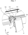
- Fig. 7 is a perspective view of tubular part 57.
- openable member 50 is provided at its left end with tubular part 57.
- Tubular part 57 is a part in a tubular shape, the part being provided with insertion hole 57a that is a circular hole in section perpendicular to the left-right direction. Insertion hole 57a opens leftward.
- Insertion part 32 formed in base frame 30 is inserted into insertion hole 57a. Insertion part 32 is a protrusion in a substantially cylindrical shape protruding rightward.
- Fig. 8 is a perspective view of bearing part 59.
- openable member 50 is provided at its right end with bearing part 59.
- Bearing part 59 is a part in a C-shape in section, the part being provided with fitting recess 59a that is a circular recess in the section perpendicular to the left-right direction.
- fitting recess 59a Inside fitting recess 59a, shaft part 34 formed on base frame 30 is fitted.
- Shaft part 34 is a protrusion in a columnar shape protruding leftward.
- Fitting recess 59a is provided coaxially with insertion hole 57a. That is, a virtual axis passing through the center of the circle formed by insertion hole 57a passes through the center of the circle formed by fitting recess 59a.
- openable member 50 is rotatable about an axis of rotation parallel to the left-right direction as described above.
- first holders 57b, 59b are each located on an opposite side in main body 51 in the circumferential direction.
- Second holders 57c, 59c are each formed at a position shifted from main body 51 by approximately 135° in the circumferential direction.
- stoppers 32a and 34a are formed above insertion part 32 and shaft part 34, respectively, in base frame 30.
- Stoppers 32a, 34a each have a shape provided with a protrusion protruding downward from a front end of a flat plate extending in a front-rear direction.
- the protrusion of each of stoppers 32a, 34a includes a lower end located radially inward of each of distal ends of holders 57b, 57c, 59b, 59c.
- holders 57b, 57c, 59b, 59c come into contact with corresponding stoppers 32a, 34a.
- Stoppers 32a, 34a are each provided above with a space. Thus, stoppers 32a, 34a can escape upward when being pushed up from below.
- Fig. 9 is a sectional view of openable member 50 in an open state opened at a first angle, and illustrates openable member 50 in section perpendicular to the left-right direction.
- first holders 57b, 59b come into contact with stoppers 32a, 34a from the rear, respectively, so that openable member 50 is held in the open state opened at the first angle.
- openable member 50 is opened at the first angle in the present exemplary embodiment, openable member 50 is at a rotational position rotated by about 90° from an attitude in the closed state. That is, the first angle is about 90° in the present exemplary embodiment.
- main body 51 is substantially parallel to the vertical direction.
- the first angle is about 90° and is intended to be 90° in the present exemplary embodiment, the first angle means that the first angle includes an angle slightly deviated from 90° due to fluctuation or the like, specifically means an angle within "90° ⁇ 5°", preferably an angle within "90° ⁇ 3°", and more preferably an angle within "90° ⁇ 1°".
- Fig. 10 is a sectional view of openable member 50 in an open state opened at a second angle, and illustrates openable member 50 in section perpendicular to the left-right direction.
- second holders 57c, 59c come into contact with stoppers 32a, 34a from the rear, respectively, so that openable member 50 is held in the open state opened at the second angle.
- openable member 50 is opened at the second angle in the present exemplary embodiment, openable member 50 is at a rotational position rotated by about 135° from the attitude in the closed state. That is, the second angle is about 135° in the present exemplary embodiment.
- main body 51 extends in a direction inclined forward and downward from the axis of rotation of openable member 50.
- the second angle is about 135° and is intended to be 135° in the present exemplary embodiment, the second angle means that the second angle includes an angle slightly deviated from 135° due to fluctuation or the like, specifically means an angle within "135° ⁇ 5°", preferably an angle within "135° ⁇ 3°", and more preferably an angle within "135° ⁇ 1°".
- Fig. 11 is a sectional view of openable member 50 at the time of attachment and detachment, and illustrates bearing part 59 in section perpendicular to the left-right direction.
- bearing part 59 is in a C-shape in section. That is, openable member 50 is provided with fitting opening 59d that passes through bearing part 59 in the radial direction and communicates with fitting recess 59a.
- Fitting opening 59d in the present exemplary embodiment faces upward when openable member 50 is in the closed state.
- shaft part 34 When shaft part 34 is fitted into fitting recess 59a, shaft part 34 can pass through fitting opening 59d.
- openable member 50 can be attached to and detached from base frame 30.
- shaft part 34 includes side surfaces parallel to the left-right direction, the side surfaces including a pair of planar parts 34b and a pair of curved surface parts 34c.
- the pair of planar parts 34b are planes parallel to each other.
- the pair of curved surface parts 34c are curved surfaces curved in an arc shape about the axis of rotation of openable member 50, and connect the pair of planar parts 34b to each other.
- An interval between planar parts 34b is smaller than an interval between curved surface parts 34c.
- Fitting opening 59d is configured to have a size in the circumferential direction, the size being smaller than the interval between planar parts 34b to prevent shaft part 34 from easily coming off from bearing part 59.
- bearing part 59 is easily attached to and detached from shaft part 34 when moving parallel to planar parts 34b in the radial direction because the interval between planar parts 34b is smaller than the interval between curved surface parts 34c as illustrated in Fig. 11 .
- bearing part 59 can be attached to and detached from shaft part 34 when openable member 50 is opened at an angle between the first angle and the second angle as illustrated in Fig. 11 .
- bearing part 59 can be attached to and detached from shaft part 34 when openable member 50 in the open state opened at the first angle is lifted forward by a hand of an operator or the like to bring second holders 57c, 59c into contact with stoppers 32a, 34a, respectively, from the front.
- Installation plate 40 is fixed to wall surface W by fastening a screw or the like.
- connection pipe housing 33 causes indoor-side pipes 17, 19 to be routed leftward in connection pipe housing 33.
- distal end 17a of indoor-side liquid pipe 17 is disposed above openable member 50.
- connection pipe housing 33 connect inner-outer connection pipes P1, P2 to indoor-side pipes 17, 19, respectively.
- the operator opens openable member 50 at the first angle or the second angle, or removes openable member 50 from base frame 30.
- openable member 50 When openable member 50 is opened at the first angle, the operator grips main body 51 and pulls it downward. As a result, mountain-shaped protrusions 52 of openable member 50 are detached from mountain-shaped recesses 36 of base frame 30, and openable member 50 is rotated downward about the axis of rotation. As openable member 50 is rotated, first holder 57b, 59b is moved backward and upward along the circumferential direction to come into contact with stoppers 32a, 34a, respectively. When the operator further rotates openable member 50, first holders 57b, 59b get over stoppers 32a, 34a, respectively. As a result, openable member 50 is opened at the first angle.
- openable member 50 When openable member 50 is opened at the second angle, the operator further rotates openable member 50 opened at the first angle forward. As a result, second holder 57c, 59c are moved backward and upward along the circumferential direction to come into contact with stoppers 32a, 34a, respectively. When the operator further rotates openable member 50, second holders 57c, 59c get over stoppers 32a, 34a, respectively. As a result, openable member 50 is opened at the second angle.
- connection pipe housing 33 After moving openable member 50 from below connection pipe housing 33, the operator performs connection work between indoor-side pipes 17, 19 and inner-outer connection pipes P1, P2. Moving openable member 50 facilitates securing a work space, so that the operator can easily perform the connection work.
- openable member 50 When closing openable member 50 opened at the first angle or the second angle, the operator rotates openable member 50 backward and upward. As a result, mountain-shaped protrusions 52 of openable member 50 are fitted into respective mountain-shaped recesses 36 of base frame 30 to hold openable member 50 in the closed state.
- the operator hooks lower fixing claw 38 formed on lower fixing part 37 of base frame 30 on first hook part 41.
- the operator simultaneously causes openable member fixing claw 53 formed on openable member 50 to be locked to second hook part 43.
- rattling and displacement of indoor unit 1 are suppressed.
- the operator inserts a fastener into elongated hole 39 formed in lower fixing part 37 of base frame 30 to fasten lower fixing part 37 and installation plate 40.
- the operator inserts a fastener into not only fastening hole 56 formed in openable member 50 but also screw hole 47 formed in installation plate 40 to fasten inclined surface 55 of openable member 50 and fastening surface 45 of installation plate 40.
- indoor unit 1 is fixed to further suppress rattling and displacement of indoor unit 1.
- the operator can also easily fasten inclined surface 55 and fastening surface 45 because inclined surface 55 faces downward and obliquely forward.
- the air conditioner includes indoor unit 1 of a wall-mounted type attached to wall surface W with installation plate 40 interposed therebetween in the present exemplary embodiment.
- Indoor unit 1 includes housing 10 that houses indoor heat exchanger 11, and indoor-side liquid pipe 17 and indoor-side gas pipe 19 that are drawn to the outside from back surface part 31 of housing 10.
- Back surface part 31 is provided with connection pipe housing 33 capable of housing indoor-side liquid pipe 17 and indoor-side gas pipe 19, and connection pipe housing 33 is provided below with openable member 50 that is rotated to open and close.
- Openable member 50 is configured to include openable member fixing claw 53, and to be capable of not only holding openable member fixing claw 53 in a state of being locked to installation plate 40 in the closed state, but also exposing connection pipe housing 33 downward when brought into the open state.
- connection pipe housing 33 to be exposed downward when indoor unit 1 is installed, but also openable member fixing claw 53 to be locked to installation plate 40 after indoor unit 1 is installed.
- the air conditioner according to the present exemplary embodiment can facilitate connection between indoor-side pipes 17, 19 and inner-outer connection pipes P1, P2 during installation of indoor unit 1 while suppressing rattling of indoor unit 1 after the installation.
- openable member 50 may be configured to include first holders 57b, 59b that are respectively in contact with first stopper 32a and second stopper 34a formed on base frame 30 of housing 10 to hold openable member 50 in the open state opened at the first angle.
- the air conditioner according to the present exemplary embodiment can facilitate connection between indoor-side pipes 17, 19 and inner-outer connection pipes P1, P2 during installation of indoor unit 1.
- the first angle is about 90° in the present exemplary embodiment, so that distal end 17a of indoor-side liquid pipe 17 is likely to be exposed downward to enable the connection work to be easily performed.
- openable member 50 may be configured to include second holders 57c, 59c that are respectively in contact with first stopper 32a and second stopper 34a formed on base frame 30 of housing 10 to hold openable member 50 in the open state opened at the second angle.
- the air conditioner according to the present exemplary embodiment can facilitate connection between indoor-side pipes 17, 19 and inner-outer connection pipes P1, P2 during installation of indoor unit 1.
- the second angle is about 135° larger than the first angle in the present exemplary embodiment, so that the connection work can be easily performed.
- openable member 50 may be configured to be detachably attached to housing 10.
- connection pipe housing 33 This configuration enables not only connection pipe housing 33 to be exposed downward by removing openable member 50 when indoor unit 1 is installed, but also openable member fixing claw 53 to be locked to installation plate 40 after indoor unit 1 is installed.
- the air conditioner according to the present exemplary embodiment can facilitate connection between indoor-side pipes 17, 19 and inner-outer connection pipes P1, P2 during installation of indoor unit 1 while suppressing rattling of indoor unit 1 after the installation.
- openable member 50 may be configured to include tubular part 57 in a hollow cylindrical shape and bearing part 59 that is in a C-shape in section and provided coaxially with tubular part 57, and base frame 30 of housing 10 may be configured to include insertion part 32 inserted into tubular part 57 and shaft part 34 onto which bearing part 59 is fitted.
- the air conditioner according to the present exemplary embodiment can facilitate connection between indoor-side pipes 17, 19 and inner-outer connection pipes P1, P2 during installation of indoor unit 1 with the simple structure while suppressing rattling of indoor unit 1 after the installation.
- the side surfaces of shaft part 34 may be configured to include the pair of flat planar parts 34b provided parallel to each other and the pair of curved surface parts 34c curved outward and connecting planar parts 34b to each other, and the interval between planar parts 34b may be configured to be smaller than the interval between curved surface parts 34c.
- This configuration allows bearing part 59 to be easily attached to and detached from shaft part 34 when bearing part 59 is moved parallel to planar parts 34b.
- the air conditioner according to the present exemplary embodiment can prevent openable member 50 from being unintentionally detached.
- openable member 50 may be configured to include fastening hole 56 formed to enable openable member 50 and installation plate 40 to be fastened when openable member 50 is in the closed state.
- This configuration enables the air conditioner according to the present exemplary embodiment to more easily suppress rattling of indoor unit 1 after installation.
- openable member 50 may be configured to be provided below distal end 17a of indoor-side liquid pipe 17 housed in connection pipe housing 33.
- This configuration enables the air conditioner according to the present exemplary embodiment to facilitate connection between indoor-side liquid pipe 17 and inner-outer connection pipe P1 even when distal end 17a of indoor-side liquid pipe 17 is at a position covered with openable member 50 from below.
- the first exemplary embodiment has been described to exemplify the techniques in the present disclosure.
- the techniques in the present disclosure are not limited thereto, and can also be applied to exemplary embodiments in which changes, replacements, additions, omissions, and the like have been made. Additionally, a new exemplary embodiment can be made by combining components described in the first exemplary embodiment.
- openable member 50 is provided below distal end 17a of indoor-side liquid pipe 17 as an example of openable member 50
- this configuration is an example.
- Openable member 50 is only required such that it is configured to be located below connection pipe housing 33 to enable openable member fixing claw 53 to be held in a state of being locked to installation plate 40.
- a position where openable member 50 is provided is not limited to a position below distal end 17a of indoor-side liquid pipe 17.
- Openable member 50 may be provided below distal end 19a of indoor-side gas pipe 19, for example.
- Openable member 50 also may be provided at a position not overlapping distal ends 17a, 19a of indoor-side pipes 17, 19 in plan view in connection pipe housing 33.
- connection pipe housing 33 to be exposed downward by opening openable member 50, so that a work space for connecting distal ends 17a, 19a of indoor-side pipes 17, 19 to inner-outer connection pipes P1, P2, respectively, is likely to be secured.
- openable member 50 when openable member 50 is located below distal ends 17a, 19a of indoor-side pipes 17, 19, an effect of improvement in workability by opening openable member 50 can be increased.
- indoor unit 1 includes one openable member 50
- this configuration is an example.
- a plurality of openable members 50 may be provided.
- indoor unit 1 may be configured to include a plurality of openable members 50.
- the first exemplary embodiment does not replace lower fixing part 37 away from distal ends 17a, 19a of indoor-side pipes 17, 19 with openable member 50 to prevent complication of the configuration without impairing the workability.
- An air conditioner of technique 1 includes an indoor unit of a wall-mounted type attached to a wall surface with an installation plate interposed therebetween.
- the indoor unit includes a housing that houses an indoor heat exchanger, an indoor-side pipe that is drawn out from a back surface of the housing to the outside, a connection pipe housing that is formed on the back surface and is capable of housing the indoor-side pipe, and an openable member that is provided below the connection pipe housing to be opened and closed by being rotated.
- the openable member includes a fixing claw, and is capable of not only holding the fixing claw in a state locked to the installation plate in a closed state, but also exposing the connection pipe housing downward when brought into an open state.
- the air conditioner of technique 1 can facilitate connection between the indoor-side pipe and an inner-outer connection pipe during installation of the indoor unit while suppressing rattling of the indoor unit after the installation.
- the air conditioner described in technique 1 includes an air conditioner of technique 2 that is configured such that the openable member includes a first holder that is in contact with the housing to hold the openable member in the open state opened at a first angle.
- the air conditioner of technique 2 can facilitate connection between the indoor-side pipe and the inner-outer connection pipe during installation of the indoor unit.
- the air conditioner described in technique 2 includes an air conditioner of technique 3 that is configured such that the openable member includes a second holder that is in contact with the housing to hold the openable member in the open state opened at a second angle.
- the air conditioner of technique 3 can facilitate connection between the indoor-side pipe and the inner-outer connection pipe during installation of the indoor unit.
- the air conditioner described in any one of techniques 1 to 3 includes an air conditioner of technique 4 that is configured such that the openable member is detachably attached to the housing.
- the air conditioner of technique 4 can facilitate connection between the indoor-side pipe and the inner-outer connection pipe during installation of the indoor unit while suppressing rattling of the indoor unit after the installation.
- the air conditioner described in any one of techniques 1 to 4 includes an air conditioner of technique 5 that is configured such that the openable member includes a tubular part in a hollow cylindrical shape and a bearing part that is in a C-shape in section and provided coaxially with the tubular part, and the housing includes an insertion part inserted into the tubular part and a shaft part onto which the bearing part is fitted.
- the air conditioner of technique 5 can facilitate connection between the indoor-side pipe and the inner-outer connection pipe during installation of the indoor unit while suppressing rattling of the indoor unit after the installation.
- the air conditioner described in technique 5 includes an air conditioner of technique 6 that is configured such that the shaft part includes side surfaces including a pair of flat planar parts provided parallel to each other and a pair of curved surface parts curved outward and connecting the flat planar parts to each other, and the planar parts are provided at an interval smaller than an interval between the curved surface parts.
- This configuration allows the bearing part to be easily attached to and detached from the shaft part when the bearing part is moved parallel to the planar parts.
- the air conditioner of technique 6 can prevent the openable member from being unintentionally detached.
- the air conditioner described in any one of techniques 1 to 6 includes an air conditioner of technique 7 that is configured such that the openable member includes a fastening hole formed to enable the openable member and the installation plate to be fastened when the openable member is in the closed state.
- This configuration enables the air conditioner of technique 7 to more easily suppress rattling of the indoor unit after installation.
- the air conditioner described in any one of techniques 1 to 7 includes an air conditioner of technique 8 that is configured such that the openable member is provided below a distal end of the indoor-side pipe while being housed in the connection pipe housing.
- This configuration enables the air conditioner of technique 8 to facilitate connection between the indoor-side liquid pipe and the inner-outer connection pipe even when the distal end of the indoor-side pipe is at a position covered with the openable member from below.
- the air conditioner described in any one of techniques 1 to 8 includes an air conditioner of technique 9 that is configured such that the indoor unit is provided with a plurality of openable members.
- This configuration enables the air conditioner of technique 9 to secure a wide work space by opening the plurality of openable members when the indoor-side pipe is connected to the inner-outer connection pipe.
- the present disclosure is applicable to an air conditioner. Specifically, the present disclosure is applicable to a household or business air conditioner including an indoor unit of a wall-mounted type, for example.
Landscapes
- Engineering & Computer Science (AREA)
- Chemical & Material Sciences (AREA)
- Combustion & Propulsion (AREA)
- Mechanical Engineering (AREA)
- General Engineering & Computer Science (AREA)
- Air Filters, Heat-Exchange Apparatuses, And Housings Of Air-Conditioning Units (AREA)
Applications Claiming Priority (1)
| Application Number | Priority Date | Filing Date | Title |
|---|---|---|---|
| JP2023188573A JP2025076754A (ja) | 2023-11-02 | 2023-11-02 | 空気調和機 |
Publications (1)
| Publication Number | Publication Date |
|---|---|
| EP4549825A1 true EP4549825A1 (fr) | 2025-05-07 |
Family
ID=93288875
Family Applications (1)
| Application Number | Title | Priority Date | Filing Date |
|---|---|---|---|
| EP24208845.8A Pending EP4549825A1 (fr) | 2023-11-02 | 2024-10-25 | Climatiseur |
Country Status (3)
| Country | Link |
|---|---|
| EP (1) | EP4549825A1 (fr) |
| JP (1) | JP2025076754A (fr) |
| CN (1) | CN119934672A (fr) |
Citations (4)
| Publication number | Priority date | Publication date | Assignee | Title |
|---|---|---|---|---|
| JPH08285365A (ja) | 1995-04-10 | 1996-11-01 | Fujitsu General Ltd | 空気調和機の据付装置 |
| JP3071081B2 (ja) * | 1994-01-14 | 2000-07-31 | 三洋電機株式会社 | 空気調和機 |
| JP2015010731A (ja) * | 2013-06-27 | 2015-01-19 | パナソニック株式会社 | 空気調和機 |
| EP4040054A1 (fr) * | 2021-02-05 | 2022-08-10 | Panasonic Intellectual Property Management Co., Ltd. | Climatiseur à montage mural |
-
2023
- 2023-11-02 JP JP2023188573A patent/JP2025076754A/ja active Pending
-
2024
- 2024-10-25 EP EP24208845.8A patent/EP4549825A1/fr active Pending
- 2024-10-31 CN CN202411538015.3A patent/CN119934672A/zh active Pending
Patent Citations (4)
| Publication number | Priority date | Publication date | Assignee | Title |
|---|---|---|---|---|
| JP3071081B2 (ja) * | 1994-01-14 | 2000-07-31 | 三洋電機株式会社 | 空気調和機 |
| JPH08285365A (ja) | 1995-04-10 | 1996-11-01 | Fujitsu General Ltd | 空気調和機の据付装置 |
| JP2015010731A (ja) * | 2013-06-27 | 2015-01-19 | パナソニック株式会社 | 空気調和機 |
| EP4040054A1 (fr) * | 2021-02-05 | 2022-08-10 | Panasonic Intellectual Property Management Co., Ltd. | Climatiseur à montage mural |
Also Published As
| Publication number | Publication date |
|---|---|
| CN119934672A (zh) | 2025-05-06 |
| JP2025076754A (ja) | 2025-05-16 |
Similar Documents
| Publication | Publication Date | Title |
|---|---|---|
| US11566810B2 (en) | Air conditioner indoor unit, and air conditioner | |
| EP2469194B1 (fr) | Conditionneur d'air mural | |
| KR102336374B1 (ko) | 에어컨 실내기 및 에어컨 | |
| MX2007014688A (es) | Aparato para distribucion de aire. | |
| CN106123275B (zh) | 空调器室内机 | |
| KR20200083947A (ko) | 에어컨 실내기 및 에어컨 | |
| EP4040054A1 (fr) | Climatiseur à montage mural | |
| CN206905122U (zh) | 空调室内机和空调器 | |
| EP4549825A1 (fr) | Climatiseur | |
| CN109307323A (zh) | 空调室内机和空调器 | |
| JP2004093049A (ja) | 空気調和機 | |
| JP4265467B2 (ja) | 換気扇 | |
| CN109307321A (zh) | 空调室内机和空调器 | |
| CN214791449U (zh) | 用于空调器的安装板和具有其的空调器 | |
| JP3039410B2 (ja) | 空気調和装置の風向調整装置 | |
| CN216132045U (zh) | 空气净化系统 | |
| JPH07208758A (ja) | 空気調和機 | |
| JP2988329B2 (ja) | 空気調和装置の吸込グリル支持構造 | |
| CN119163618B (zh) | 一种空调鼓风机 | |
| JP7484321B2 (ja) | 空気調和装置用室内機 | |
| CN214791491U (zh) | 空调器 | |
| JP7843874B2 (ja) | 仮掛け構造、室内機、および空気調和機 | |
| JPH08338644A (ja) | 空気調和機 | |
| CN213931407U (zh) | 面板组件及空调器 | |
| JP2597626Y2 (ja) | 空気調和機 |
Legal Events
| Date | Code | Title | Description |
|---|---|---|---|
| PUAI | Public reference made under article 153(3) epc to a published international application that has entered the european phase |
Free format text: ORIGINAL CODE: 0009012 |
|
| STAA | Information on the status of an ep patent application or granted ep patent |
Free format text: STATUS: THE APPLICATION HAS BEEN PUBLISHED |
|
| AK | Designated contracting states |
Kind code of ref document: A1 Designated state(s): AL AT BE BG CH CY CZ DE DK EE ES FI FR GB GR HR HU IE IS IT LI LT LU LV MC ME MK MT NL NO PL PT RO RS SE SI SK SM TR |
|
| STAA | Information on the status of an ep patent application or granted ep patent |
Free format text: STATUS: REQUEST FOR EXAMINATION WAS MADE |
|
| 17P | Request for examination filed |
Effective date: 20251107 |