EP4040936A1 - Installationsvorrichtung für substratträgerstifte und verfahren zum installieren eines substratträgerstiftes - Google Patents
Installationsvorrichtung für substratträgerstifte und verfahren zum installieren eines substratträgerstiftes Download PDFInfo
- Publication number
- EP4040936A1 EP4040936A1 EP19947611.0A EP19947611A EP4040936A1 EP 4040936 A1 EP4040936 A1 EP 4040936A1 EP 19947611 A EP19947611 A EP 19947611A EP 4040936 A1 EP4040936 A1 EP 4040936A1
- Authority
- EP
- European Patent Office
- Prior art keywords
- substrate support
- support pin
- pin
- holding
- substrate
- Prior art date
- Legal status (The legal status is an assumption and is not a legal conclusion. Google has not performed a legal analysis and makes no representation as to the accuracy of the status listed.)
- Pending
Links
- 239000000758 substrate Substances 0.000 title claims abstract description 127
- 238000009434 installation Methods 0.000 title claims abstract description 30
- 238000000034 method Methods 0.000 title claims description 11
- 239000012530 fluid Substances 0.000 description 6
- 230000007246 mechanism Effects 0.000 description 4
- 230000004308 accommodation Effects 0.000 description 2
- 238000010586 diagram Methods 0.000 description 1
- 230000000694 effects Effects 0.000 description 1
- 238000003780 insertion Methods 0.000 description 1
- 230000037431 insertion Effects 0.000 description 1
- 239000000696 magnetic material Substances 0.000 description 1
- 238000012986 modification Methods 0.000 description 1
- 230000004048 modification Effects 0.000 description 1
- NJPPVKZQTLUDBO-UHFFFAOYSA-N novaluron Chemical compound C1=C(Cl)C(OC(F)(F)C(OC(F)(F)F)F)=CC=C1NC(=O)NC(=O)C1=C(F)C=CC=C1F NJPPVKZQTLUDBO-UHFFFAOYSA-N 0.000 description 1
- 238000007650 screen-printing Methods 0.000 description 1
Images




Classifications
-
- H—ELECTRICITY
- H05—ELECTRIC TECHNIQUES NOT OTHERWISE PROVIDED FOR
- H05K—PRINTED CIRCUITS; CASINGS OR CONSTRUCTIONAL DETAILS OF ELECTRIC APPARATUS; MANUFACTURE OF ASSEMBLAGES OF ELECTRICAL COMPONENTS
- H05K13/00—Apparatus or processes specially adapted for manufacturing or adjusting assemblages of electric components
- H05K13/04—Mounting of components, e.g. of leadless components
-
- H—ELECTRICITY
- H05—ELECTRIC TECHNIQUES NOT OTHERWISE PROVIDED FOR
- H05K—PRINTED CIRCUITS; CASINGS OR CONSTRUCTIONAL DETAILS OF ELECTRIC APPARATUS; MANUFACTURE OF ASSEMBLAGES OF ELECTRICAL COMPONENTS
- H05K13/00—Apparatus or processes specially adapted for manufacturing or adjusting assemblages of electric components
- H05K13/0061—Tools for holding the circuit boards during processing; handling transport of printed circuit boards
- H05K13/0069—Holders for printed circuit boards
Definitions
- the present disclosure relates to a substrate support pin setting jig used when a substrate support pin for supporting a circuit substrate is installed on a support base, and a method for installing the substrate support pin which is a method for installing the substrate support pin on the support base.
- Patent Literature 1 discloses a support pin base that holds multiple substrate support pins (hereinafter, referred to as "support pin”), and includes (a) a main body fixedly installed on a support base that can be lifted and lowered with respect to a circuit substrate, (b) multiple pin accommodation holes formed so as to penetrate the main body in the up-down direction, and (c) a shutter plate inserted so as to be relatively movable in an intermediate portion of the main body in the up-down direction and slidable between a holding position where the support pin is held from below and a non-holding position where the support pin is not held.
- support pin includes (a) a main body fixedly installed on a support base that can be lifted and lowered with respect to a circuit substrate, (b) multiple pin accommodation holes formed so as to penetrate the main body in the up-down direction, and (c) a shutter plate inserted so as to be relatively movable in an intermediate portion of the main body in the up-down direction and slidable between a holding position where the support pin
- a jig base is carried into above the support pin base in a state where the multiple support pins are accommodated in the multiple pin accommodation holes.
- a magnet is fitted into a portion of the jig base corresponding to a reference position where the support pin is to be installed.
- the support pin base is raised to bring into contact with the magnet and the support pin, and then the support pin base is lowered.
- the support pin in contact with the magnet protrudes upward with respect to the other support pins, so that the shutter plate is moved to the holding position.
- the support pin is installed at the reference position of the support base via the support pin base.
- Patent Literature 1 JP-A-2008-153457
- a substrate support pin installation jig (hereinafter, may be referred to as "jig") according to the present disclosure includes a main body configured to move relative to a support base, multiple pin accommodating portions provided in the main body, and a positioned portion used for positioning on the support base.
- the substrate support pin is accommodated and held in at least one of the multiple pin accommodating portions of the jig.
- the jig is placed on the support base in a state where the jig is positioned by the positioned portion.
- the at least one substrate support pin is installed on the support base, and then the jig is removed.
- each of the at least one substrate support pin is installed at a predetermined position on the support base.
- the jig and a method for installing the substrate support pin according to the present disclosure are not described in Patent Literature 1, and are novel.
- a mounter illustrated in Fig. 1 mounts electronic component (hereinafter, may be referred to as "component”) s to circuit substrate (hereinafter, may be referred to as a substrate) P, and includes device main body 2, circuit substrate conveyance and holding device 4, component supply device 6, head moving device 8, and the like.
- Circuit substrate conveyance and holding device 4 conveys and holds substrate P, and includes substrate conveyance device 10 and substrate holding device 12 illustrated in Fig. 2 .
- the conveyance direction of substrate P is the x direction
- the width direction of substrate P is the y direction
- the thickness direction of substrate P is the z direction.
- Each of the y direction and the z direction is the front-rear direction and the up-down direction of the mounter. These x direction, y direction, and z direction are orthogonal to one another.
- Component supply device 6 supplies component s to be mounted on substrate P, and in the present example, includes multiple tape feeders 14.
- Head moving device 8 holds and moves work head 16 in the x and y directions.
- Work head 16 includes suction nozzle 17 as an example of a component holder for holding component s, pin holder 19 for holding substrate support pin (hereinafter, may be referred to as "support pin") 18 illustrated in Fig. 9 and the like, and a lifting and lowering mechanism (not illustrated) for moving each of suction nozzle 17 and pin holder 19 in the z direction with respect to the head main body.
- Suction nozzle 17 is moved between component supply device 6 and substrate P by the movement of work head 16.
- Component s supplied by component supply device 6 is mounted on a predetermined position of substrate P.
- pin holder 19 is moved between an initial position and a reference position described later.
- support pin 18 installed at the initial position is moved to the reference position and installed.
- automatic pin installation device 20 for automatically installing support pin 18 at the reference position is configured, including pin holder 19, head moving device 8, and the like.
- substrate conveyance device 10 conveys substrate P in the x direction, and includes a pair of side plates 21 and 22 provided so as to be separated in the y direction, and a pair of conveyor mechanisms 23 and 24 attached to the pair of side plates 21 and 22, as illustrated in Fig. 2 .
- the pair of conveyor mechanisms 23 and 24 includes electric motor 26 (refer to Fig. 3 ) as a driving source, multiple pulleys (not illustrated), belt 28 hung on the multiple pulleys, and the like. Each of the multiple pulleys is rotatably held by side plates 21 and 22. By the driving of electric motor 26, the multiple pulleys are rotated, belt 28 is moved, and substrate P mounted on belt 28 is conveyed.
- Reference symbol 30 represents a support rail for supporting belt 28.
- Substrate holding device 12 is a device for holding substrate P, and includes support base 40, multiple support pins 18, lifting and lowering device 44 for lifting and lowering support base 40, clamping device 46 for clamping substrate P, and the like.
- Support base 40 is manufactured with a magnetic material and is located below substrate conveyance device 10. Support base 40 is relatively lifted and lowered with respect to substrate P by lifting and lowering device 44. As illustrated in Figs. 10 and 11 , support base 40 is provided with x-direction positioning portion 48, which is a component of a positioning portion for determining a position of substrate support pin installation jig 100 described later.
- X-direction positioning portion 48 includes support post 48h fixed to support base 40, and engagement protrusion portion 48a attached to support post 48h and extending generally in the x direction. Engagement protrusion portion 48a may be expanded or contracted, for example, the amount of protrusion with respect to support post 48h can be changed by a screw mechanism or the like.
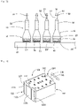
- Support pin 18 supports substrate P from below, as illustrated in Fig. 9 , has a stepped shape extending in the longitudinal direction, and includes bottom portion 50 having a large diameter, tip end portion 52 having a small diameter, and intermediate portion 54 between bottom portion 50 and tip end portion 52, having a medium diameter.
- Bottom portion 50 includes magnet 56 provided inside main body 55, and magnet holding portion 58 that holds magnet 56 from below.
- Support pin 18 is installed on support base 40 by magnet 56.
- magnet holding portion 58 is interposed between magnet 56 and support base 40, the surface of support base 40 is hardly scratched.
- Engaged portion 59 is provided on tip end portion 52.
- Engaged portion 59 includes three protruding rods 60 (refer to Fig. 10 ) extending in the radial direction at intervals of central angles of 120°.
- Pin support member 19 holds support pin 18 by gripping engaged portion 59.
- lifting and lowering device 44 includes fluid cylinder 64 serving as a driving source and guide device 65.
- Support base 40 is attached to piston rod 66 of a piston (not illustrated) of fluid cylinder 64 via a lifting and lowering base.
- fluid cylinder 64 the supply and discharge of the fluid are controlled by the control of fluid supply and discharge control device (refer to Fig. 3 ) 68, so that lifting and lowering of support base 40 is controlled.
- Clamping device 46 includes a pair of side plates 21 and 22, a pair of receiving members 70 and 71, and a pair of push-up portions 73 and 74.
- Receiving members 70 and 71 press substrate P from above, and are provided so as to extend in the x direction.
- each of receiving members 70 and 71 protrudes in a direction facing each other from the pair of side plates 21 and 22, and the tip end portion is located inside belt 28.
- Push-up portions 73 and 74 include push-up plates 76 and 77, and holding bodies 78 and 79 for holding each of push-up plates 76 and 77 at the lower portions.
- Push-up plates 76 and 77 are held by holding bodies 78 and 79 in a state where the upper portions are protruded, and the upper end portions are located inside belt 28 and below the tip end portions of the pair of receiving members 70 and 71.
- Holding bodies 78 and 79 are held by side plates 21 and 22 in a state where they can be relatively lifted and lowered and are biased downward by a spring (not illustrated).
- Bolts 80 and 81 serving as engaging portions are attached to lower end portions of holding bodies 78 and 79, respectively.
- support base 40 As support base 40 is raised, the upper surface of support base 40 abuts on bolts 80 and 81, so that push-up portions 73 and 74 are lifted. Substrate P held by belt 28 is lifted by push-up plates 76 and 77, and is clamped by receiving members 70 and 71 and push-up plates 76 and 77. In addition, substrate P is supported from below by support pin 18.
- the mounter includes control device 90 mainly including a computer.
- Control device 90 includes an execution section, a storage section, an input and output section, and the like (not illustrated), and head moving device 8, electric motor 26 of substrate conveyance device 10, fluid supply and discharge device 68 of lifting and lowering device 44 of substrate holding device 12, and the like are connected to the input and output section via a drive circuit.
- Each of one or more support pins 18 is automatically installed by automatic pin installation device 20 at the reference position (reference position means a position determined in advance based on the shape and characteristics of substrate P, and the mounting position of component s) on support base 40, and prior to the installation, the operator is required to install one or more support pins 18 at each of the predetermined initial positions.
- reference position means a position determined in advance based on the shape and characteristics of substrate P, and the mounting position of component s
- the initial position of support pin 18 is often a position where it is difficult for the operator to work. Accordingly, in the present example, support pin 18 is installed at the initial position, that is, the initial setting is performed using substrate support pin installation jig (hereinafter, may be referred to as "jig") 100.
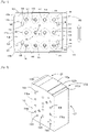
- Jig 100 is not fixedly provided on support base 40, is attachable and detachable and relatively movable, and includes main body 102 and holding member 104, as illustrated in Fig. 4 .
- main body 102 has a generally rectangular parallelepiped shape, and multiple pin accommodating portions 106 capable of accommodating support pins 18 are provided inside main body 102.
- Support pin 18 is accommodated in pin accommodating portion 106 so as to be movable in the longitudinal direction thereof.
- Holding member 104 holds support pin 18 accommodated in pin accommodating portion 106, and is attached to main body 102 so as to be relatively movable, that is, to be slidable.
- pin accommodating portion 106 is a through-hole extending through a pair of surfaces 112 and 114 of main body 102 facing each other, and is formed in parallel with each other and arranged side by side at intervals.
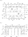
- Each of pin accommodating portions 106 has a stepped shape having different hole diameters, and includes large-diameter hole portion 108, medium-diameter hole portion 109, and small-diameter hole portion 110.
- the diameter of large-diameter hole portion 108 is larger than the diameter of bottom portion 50 of support pin 18, the diameter of medium-diameter hole portion 109 is larger than the diameter of intermediate portion 54 of support pin 18, and the diameter of small-diameter hole portion 110 is larger than the outer diameter of engaged portion 59 of support pin 18.
- the outer diameter of engaged portion 59 is determined by the tip end portions of three protruding rods 60.
- Opening 110a of small-diameter hole portion 110 of pin accommodating portion 106 is located on surface 112 of main body 102, and opening 108a of large-diameter hole portion 108 is located on surface 114.
- multiple pin holes 120 are provided on surface 112.
- Front surface 122 of main body 102 has a stepped shape.
- Front surface 122 includes first surface 122a, second surface 122b, and third surface 122c that are located at different distances from rear surface 123 facing front surface 122, and cross-section 122d between second surface 122b and third surface 122c.
- Stepped surface 122d and first surface 122a extend in a direction intersecting each other, for example, in a direction orthogonal to each other.
- positioned portion 124 is configured to include first surface 122a, stepped surface 122d, and the like.
- holding member 104 has a plate shape having a generally rectangular shape, and through-hole 130 having large-diameter hole portion 132 and small-diameter hole portion 134 communicating with each other are provided at each of positions of holding member 104 corresponding to pin accommodating portion 106 of main body 102.
- the diameter of large-diameter hole portion 132 is larger than the outer diameter of engaged portion 59 of support pin 18, and the diameter of small-diameter hole portion 134 is smaller than the outer diameter of engaged portion 59 and larger than the diameter of tip end portion 52.
- long hole 140 of holding member 104 is formed at each of positions corresponding to multiple pin holes 120 of main body 102.
- Long hole 140 extends in a direction parallel to the direction where large-diameter hole portion 132 and small-diameter hole portion 134 of through-hole 130 are arranged side by side, and holding member 104 is slidably held in long hole 140 by pin 142 attached to pin hole 120 on surface 112 of main body 102, as illustrated in Figs. 4 and 10 .
- Holding member 104 is slidable along surface 112 between a non-holding position where large-diameter hole portion 132 corresponds to opening 110a and a holding position where small-diameter hole portion 134 corresponds to opening 110a.
- the limit of the slide movement of holding member 104 is specified by pin 142 and both end edges of long hole 140.
- holding member 104 engages with engaged portion 59 of support pin 18 to hold support pin 18.
- the holding of support pin 18 is released without engaging with engaged portion 59 of support pin 18.
- protrusion portions 128 and 129 protruding outward are provided on both end portions of holding member 104 in the extending direction of long hole 140, respectively, and function as handles when holding member 104 is moved.
- At least one support pin 18 is held by jig 100 (holding step).
- each of at least one support pin 18 is accommodated in at least one of multiple pin accommodating portions 106 of main body 102.
- Support pin 18 is inserted through opening 108a of large-diameter hole portion 108, and tip end portion 52, that is, engaged portion 59, is in a posture of protruding from opening 110a of main body 102 and large-diameter hole portion 132 of holding member 104. Thereafter, holding member 104 is moved to the holding position between engaged portion 59 and surface 112 of main body 102.
- holding member 104 engages with engaged portion 59 at the holding position to hold support pin 18, as illustrated in Fig. 9 .
- holding member 104 can engage with at least one of three protruding rods 60 in the holding position regardless of the phase of support pin 18.
- bottom surface 50f of bottom portion 50 of support pin 18 is located inside surface 114.
- the holding step can be referred to as an engagement step in which holding member 104 engages with engaged portion 59.
- Jig 100 for holding support pin 18 is placed on support base 40 (jig placement step).
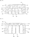
- main body 102 is placed on support base 40 in a posture in which surface 114 is a lower surface and surface 112 is an upper surface in a state where first surface 122a abuts on inner surface 76f of push-up plate 76 on the fixed side and stepped surface 122d abuts on engagement protrusion portion 48a.
- first surface 122a abuts on inner surface 76f of push-up plate 76 on the fixed side
- stepped surface 122d abuts on engagement protrusion portion 48a.
- Inner surface 76f of push-up plate 76 has a function as a y-direction positioning portion for determining the position of jig 100 in the y direction, and positioning portion 150 is configured to include y-direction positioning portion 76f, x-positioning portion 48, and the like.
- a relative position of jig 100 on support base 40 is determined by positioning portion 150 of substrate holding device 12 and positioned portion 124 of jig 100, and jig 100 is positioned (positioning step).
- support pin 18 is held by holding member 104 in a state where bottom surface 50f of bottom portion 50 is separated from support base 40, as illustrated in Fig. 9 . Accordingly, the influence of magnet 57 is reduced, and jig 100 can be moved easily on support base 40.
- Support pin 18 is installed on support base 40 (pin installing step and pin initial position installing step).
- Holding member 104 is moved to the non-holding position as indicated by the two-dot chain lines in Fig. 10 . Since the outer diameter of engaged portion 59 is smaller than the diameter of large-diameter hole portion 132 of holding member 104 and smaller than the diameter of small-diameter hole portion 110 of main body 102, the holding of support pin 18 is released, and support pin 18 drops. Bottom portion 50 of support pin 18 is installed with abutting on support base 40. As illustrated in Fig. 12 , at least one support pin 18 is installed at each of the initial positions. Thereafter, jig 100 is removed.
- At least one support pin 18 installed at the initial position of support base 40 is gripped one by one by automatic pin installation device 20, moved to the reference position, and installed.
- at least one support pin 18 can be installed in each of the reference positions (pin reference position installing step).
- component s is mounted in a state where substrate P is supported from below by support pin 18.
- At least one support pin 18 can be collectively set to the initial position using jig 100.
- the operator is not required to install support pins 18 one by one, and moreover, can accurately install support pins 18 by positioned portion 14 of jig 100 and positioning portion 150 of substrate holding device 12.
- support pin 18 can be satisfactorily installed at the reference position by automatic pin installation device 20.
- jig 100 can also be used when support pin 18 is installed in a screen printing machine.
- jig 100 can be used not only when support pin 18 is set to the initial position but also when support pin 18 is set to the reference position.
- engaged portion 59 may include four or more protruding rods 60 provided at equal intervals.
- the shape of the holding member is not limited.
- protrusion portions 206 and 207 of holding member 204 can be provided at both end portions in a direction orthogonal to the extending direction of long hole 140 of holding member 204.
- pin accommodating portion 304 provided in main body 302 may have a shape having large-diameter hole portion 308, medium-diameter hole portion 309, small-diameter hole portion 312, inclined portion 310 located between large-diameter hole portion 308 and intermediate hole portion 309 and in which the hole diameter continuously changes, inclined portion 314 located between intermediate hole portion 309 and small-diameter hole portion 312 and in which the hole diameter continuously changes, and the like.
- inclined portions 310 and 314 support pin 18 can be easily inserted into pin accommodating portion 304.
- the shape of pin accommodating portion 404 provided in main body 402 may be a shape having large-diameter hole portion 408, small-diameter hole portion 410, inclined portion 412 located between large-diameter hole portion 408 and small-diameter hole portion 410 and in which the hole diameter continuously changes, and the like.
- Pin accommodating portion 404 has a shape such that medium-diameter hole portion 109 is formed as inclined portion 412 in pin accommodating portion 106 illustrated in Fig. 7 or the like.
- inclined portion 412 facilitates the insertion of support pin 18 into pin accommodating portion 404.
- main body 102 is not limited.
- pedestals can be provided at four corners of surface 122.
- Support pin 18 can be accommodated in pin accommodating portion 106 in a state where the pedestal abuts on the working surface.
- inner surface 76f of push-up plate 76 of substrate holding device 12 is used as the y-direction positioning portion, and the present disclosure can be performed in an aspect in which various modifications and improvements are made based on the knowledge of those skilled in the art, such as a case where the y-direction positioning portion can be provided on the support base.
- substrate holding device 40: support base, 42: substrate support pin, 48: x-direction positioning portion, 76f: y-direction positioning portion, 100: substrate support pin installation jig, 102, 302, 402: main body, 104, 204: holding member, 106, 304, 404: pin accommodating portion, 122a: first surface, 122d: stepped surface, 124: positioned portion, 130: through-hole, 130: large-diameter hole portion, 132: small-diameter portion, 140: long hole, 142: pin, 150: positioning portion
Landscapes
- Engineering & Computer Science (AREA)
- Manufacturing & Machinery (AREA)
- Microelectronics & Electronic Packaging (AREA)
- Supply And Installment Of Electrical Components (AREA)
Applications Claiming Priority (1)
| Application Number | Priority Date | Filing Date | Title |
|---|---|---|---|
| PCT/JP2019/039007 WO2021064922A1 (ja) | 2019-10-02 | 2019-10-02 | 基板支持ピン設置用治具、基板支持ピン設置方法 |
Publications (2)
| Publication Number | Publication Date |
|---|---|
| EP4040936A1 true EP4040936A1 (de) | 2022-08-10 |
| EP4040936A4 EP4040936A4 (de) | 2022-10-19 |
Family
ID=75337122
Family Applications (1)
| Application Number | Title | Priority Date | Filing Date |
|---|---|---|---|
| EP19947611.0A Pending EP4040936A4 (de) | 2019-10-02 | 2019-10-02 | Installationsvorrichtung für substratträgerstifte und verfahren zum installieren eines substratträgerstiftes |
Country Status (5)
| Country | Link |
|---|---|
| US (1) | US12328822B2 (de) |
| EP (1) | EP4040936A4 (de) |
| JP (1) | JP7366146B2 (de) |
| CN (1) | CN114451079B (de) |
| WO (1) | WO2021064922A1 (de) |
Families Citing this family (3)
| Publication number | Priority date | Publication date | Assignee | Title |
|---|---|---|---|---|
| DE102021124498B3 (de) * | 2021-09-22 | 2023-01-26 | Asm Assembly Systems Gmbh & Co. Kg | Unterstützungsstift zum Unterstützen eines Substrats in einem Bestückbereich eines Bestückautomaten sowie Bestückautomat mit einem Magazin mit mehreren solcher Unterstützungsstifte. |
| CN115709447A (zh) * | 2022-11-22 | 2023-02-24 | 环鸿电子(昆山)有限公司 | 定位机构 |
| JP7784670B2 (ja) * | 2023-08-16 | 2025-12-12 | 株式会社ライジング | 基板分割装置用の治具、該治具を配置する治具配置装置 |
Family Cites Families (34)
| Publication number | Priority date | Publication date | Assignee | Title |
|---|---|---|---|---|
| US5218753A (en) * | 1989-06-22 | 1993-06-15 | Sanyo Electric Co., Ltd. | Assembling apparatus using back up pins for supporting printed circuit board |
| JPH0818280A (ja) * | 1994-06-30 | 1996-01-19 | Matsushita Electric Works Ltd | ピンの整列治具 |
| JP3377351B2 (ja) * | 1995-12-18 | 2003-02-17 | 松下電器産業株式会社 | 電子部品実装機 |
| JP4014270B2 (ja) * | 1998-01-06 | 2007-11-28 | 富士機械製造株式会社 | 基板支持ピン配置方法,配置検査方法および装置 |
| SE514024C2 (sv) * | 1998-09-11 | 2000-12-11 | Ascom Tateco Ab | Stödanordning vid montering av komponenter på ett kretskort |
| US6726195B1 (en) * | 1998-10-13 | 2004-04-27 | Dek International Gmbh | Method for ensuring planarity when using a flexible, self conforming, workpiece support system |
| KR100290733B1 (ko) * | 1999-05-10 | 2001-05-15 | 정문술 | 표면실장기의 인쇄회로기판 평면도 보정장치 |
| JP4456709B2 (ja) * | 2000-01-12 | 2010-04-28 | 富士機械製造株式会社 | 基板支持状態検査方法 |
| US6655671B2 (en) * | 2000-08-04 | 2003-12-02 | Fuji Machine Mfg. Co., Ltd. | Printed-wiring-board holding apparatus |
| US6635308B1 (en) * | 2000-08-22 | 2003-10-21 | Motorola, Inc. | Method and apparatus for electronics board retention during manufacturing operations |
| JP3855879B2 (ja) * | 2002-08-07 | 2006-12-13 | 松下電器産業株式会社 | フレキシブルプリント基板の搬送用キャリアおよびフレキシブルプリント基板への電子部品実装方法 |
| EP1676474A1 (de) * | 2003-10-23 | 2006-07-05 | Matsushita Electric Industrial Co., Ltd. | Vorrichtung zur bestimmung von support-glied-layout-mustern |
| US7259833B2 (en) * | 2004-05-28 | 2007-08-21 | Board Of Regents, The Universtiy Of Texas System | Substrate support method |
| JP4718258B2 (ja) * | 2005-07-07 | 2011-07-06 | パナソニック株式会社 | 基板支持方法及び該方法を利用する部品実装方法 |
| JP2008004856A (ja) * | 2006-06-26 | 2008-01-10 | Matsushita Electric Ind Co Ltd | 部材支持方法 |
| US7311302B1 (en) * | 2006-09-25 | 2007-12-25 | Production Solutions, Inc. | Substrate support system |
| JP4881712B2 (ja) | 2006-12-18 | 2012-02-22 | ヤマハ発動機株式会社 | バックアップピンのセッティング作業用治具、基板支持装置、表面実装機、クリーム半田印刷装置、基板検査装置及びバックアップピンのセッティング方法 |
| JP4866231B2 (ja) | 2006-12-28 | 2012-02-01 | ヤマハ発動機株式会社 | バックアップピンの回収方法、バックアップピンの供給方法、作業用治具、基板支持装置、表面実装機、クリーム半田印刷装置、及び基板検査装置 |
| JP5656446B2 (ja) * | 2010-04-28 | 2015-01-21 | 富士機械製造株式会社 | バックアップピン装置並びにバックアップピン配置方法及び配置装置 |
| JP5477330B2 (ja) * | 2011-04-28 | 2014-04-23 | パナソニック株式会社 | 電子部品実装装置 |
| JP5494588B2 (ja) * | 2011-08-08 | 2014-05-14 | パナソニック株式会社 | 電子部品実装装置用の下受けピンモジュールおよび基板下受け装置ならびに基板下受け方法 |
| US9049809B2 (en) * | 2011-12-26 | 2015-06-02 | Samsung Techwin Co., Ltd. | Apparatus and method for manufacturing double-sided mounting substrate |
| JP5747167B2 (ja) * | 2012-02-02 | 2015-07-08 | パナソニックIpマネジメント株式会社 | 下受けピンの配置方法および下受けピンの返戻方法 |
| CN109952015B (zh) * | 2013-01-30 | 2021-06-15 | 松下知识产权经营株式会社 | 下支撑销的配置确定辅助装置及配置确定辅助方法 |
| JP6151925B2 (ja) * | 2013-02-06 | 2017-06-21 | ヤマハ発動機株式会社 | 基板固定装置、基板作業装置および基板固定方法 |
| JP6001494B2 (ja) * | 2013-04-25 | 2016-10-05 | ヤマハ発動機株式会社 | バックアップピン、基板支持装置、基板処理装置 |
| US10117368B2 (en) * | 2013-09-04 | 2018-10-30 | Fuji Corporation | Board work device |
| JP6204995B2 (ja) * | 2013-12-23 | 2017-09-27 | 富士機械製造株式会社 | 対基板作業装置 |
| JP6383152B2 (ja) * | 2014-01-10 | 2018-08-29 | 平田機工株式会社 | 移載方法、保持装置及び移載システム |
| JP6521678B2 (ja) * | 2015-03-11 | 2019-05-29 | Juki株式会社 | 基板支持装置、及び電子部品実装装置 |
| GB201521345D0 (en) * | 2015-12-03 | 2016-01-20 | Protosonic Ltd | Apparatus for holding a printed circuit board |
| JP6718693B2 (ja) * | 2016-02-09 | 2020-07-08 | 株式会社Fuji | バックアップ用治具を備える装置 |
| JP2017220498A (ja) * | 2016-06-06 | 2017-12-14 | パナソニックIpマネジメント株式会社 | 部品実装装置及び部品実装方法 |
| JP6966952B2 (ja) * | 2018-02-09 | 2021-11-17 | ヤマハ発動機株式会社 | バックアップ装置 |
-
2019
- 2019-10-02 EP EP19947611.0A patent/EP4040936A4/de active Pending
- 2019-10-02 WO PCT/JP2019/039007 patent/WO2021064922A1/ja not_active Ceased
- 2019-10-02 CN CN201980100877.9A patent/CN114451079B/zh active Active
- 2019-10-02 JP JP2021550864A patent/JP7366146B2/ja active Active
- 2019-10-02 US US17/764,840 patent/US12328822B2/en active Active
Also Published As
| Publication number | Publication date |
|---|---|
| JP7366146B2 (ja) | 2023-10-20 |
| EP4040936A4 (de) | 2022-10-19 |
| CN114451079A (zh) | 2022-05-06 |
| WO2021064922A1 (ja) | 2021-04-08 |
| US12328822B2 (en) | 2025-06-10 |
| CN114451079B (zh) | 2024-02-02 |
| JPWO2021064922A1 (de) | 2021-04-08 |
| US20220322588A1 (en) | 2022-10-06 |
Similar Documents
| Publication | Publication Date | Title |
|---|---|---|
| EP3305525B1 (de) | Druckvorrichtung | |
| US12328822B2 (en) | Substrate support pin installation jig | |
| JP6898248B2 (ja) | ステンシルプリンターのためのリフトツールアセンブリ | |
| EP3043630B1 (de) | Arbeitsvorrichtung für ein substrat | |
| CN105027697B (zh) | 支撑销及支撑销自动更换系统 | |
| CN216462841U (zh) | Sim卡自动装配设备 | |
| JPH0249560B2 (de) | ||
| JPH0255177B2 (de) | ||
| JP6718693B2 (ja) | バックアップ用治具を備える装置 | |
| EP3291658B1 (de) | Arbeitsmaschine | |
| JP7218371B2 (ja) | ステンシルプリンターのためのリフトツールアセンブリ | |
| JP4340957B2 (ja) | 部品装着方法 | |
| KR101716407B1 (ko) | 스크린 프린터용 기판 안착 모듈 교체 장치 | |
| JP2004228249A (ja) | バックアップ装置および表面実装機 | |
| CN112789959B (zh) | 作业机 | |
| JP3758932B2 (ja) | マウンタの基板セット装置及びバックアップピン切替え方法 | |
| JP2025064046A (ja) | 基板支持装置および基板処理装置 | |
| US6386430B1 (en) | Mechanism for properly sizing a clamp to fit with strips of a plurality of IC package sizes | |
| JP2023154422A (ja) | Esdツーリング | |
| JPH1051197A (ja) | 電子部品実装装置および電子部品実装装置における基板下受けピンのセット方法 | |
| JP6124922B2 (ja) | 基板搬送装置及び基板搬送装置の変更方法 | |
| JPH04159088A (ja) | 部品取付装置 | |
| CN114208411A (zh) | 作业机及元件搬运方法 | |
| JP2003086613A (ja) | 電子部品実装装置 | |
| JPS6186157A (ja) | プリント基板加工機等におけるワ−ク基板の取付装置 |
Legal Events
| Date | Code | Title | Description |
|---|---|---|---|
| STAA | Information on the status of an ep patent application or granted ep patent |
Free format text: STATUS: THE INTERNATIONAL PUBLICATION HAS BEEN MADE |
|
| PUAI | Public reference made under article 153(3) epc to a published international application that has entered the european phase |
Free format text: ORIGINAL CODE: 0009012 |
|
| STAA | Information on the status of an ep patent application or granted ep patent |
Free format text: STATUS: REQUEST FOR EXAMINATION WAS MADE |
|
| 17P | Request for examination filed |
Effective date: 20220325 |
|
| AK | Designated contracting states |
Kind code of ref document: A1 Designated state(s): AL AT BE BG CH CY CZ DE DK EE ES FI FR GB GR HR HU IE IS IT LI LT LU LV MC MK MT NL NO PL PT RO RS SE SI SK SM TR |
|
| REG | Reference to a national code |
Ref country code: DE Ref legal event code: R079 Free format text: PREVIOUS MAIN CLASS: H05K0013040000 Ipc: H05K0013000000 |
|
| A4 | Supplementary search report drawn up and despatched |
Effective date: 20220916 |
|
| RIC1 | Information provided on ipc code assigned before grant |
Ipc: H05K 13/00 20060101AFI20220912BHEP |
|
| DAV | Request for validation of the european patent (deleted) | ||
| DAX | Request for extension of the european patent (deleted) | ||
| P01 | Opt-out of the competence of the unified patent court (upc) registered |
Effective date: 20230328 |
|
| GRAP | Despatch of communication of intention to grant a patent |
Free format text: ORIGINAL CODE: EPIDOSNIGR1 |
|
| STAA | Information on the status of an ep patent application or granted ep patent |
Free format text: STATUS: GRANT OF PATENT IS INTENDED |
|
| INTG | Intention to grant announced |
Effective date: 20240510 |
|
| GRAJ | Information related to disapproval of communication of intention to grant by the applicant or resumption of examination proceedings by the epo deleted |
Free format text: ORIGINAL CODE: EPIDOSDIGR1 |
|
| STAA | Information on the status of an ep patent application or granted ep patent |
Free format text: STATUS: REQUEST FOR EXAMINATION WAS MADE |
|
| STAA | Information on the status of an ep patent application or granted ep patent |
Free format text: STATUS: EXAMINATION IS IN PROGRESS |
|
| INTC | Intention to grant announced (deleted) | ||
| 17Q | First examination report despatched |
Effective date: 20240906 |