EP4050171A1 - Élément de liaison pour un châssis, ainsi que son procédé de fabrication - Google Patents
Élément de liaison pour un châssis, ainsi que son procédé de fabrication Download PDFInfo
- Publication number
- EP4050171A1 EP4050171A1 EP21158860.3A EP21158860A EP4050171A1 EP 4050171 A1 EP4050171 A1 EP 4050171A1 EP 21158860 A EP21158860 A EP 21158860A EP 4050171 A1 EP4050171 A1 EP 4050171A1
- Authority
- EP
- European Patent Office
- Prior art keywords
- connecting element
- rods
- nuts
- hollow profile
- rod
- Prior art date
- Legal status (The legal status is an assumption and is not a legal conclusion. Google has not performed a legal analysis and makes no representation as to the accuracy of the status listed.)
- Granted
Links
Images




Classifications
-
- E—FIXED CONSTRUCTIONS
- E04—BUILDING
- E04B—GENERAL BUILDING CONSTRUCTIONS; WALLS, e.g. PARTITIONS; ROOFS; FLOORS; CEILINGS; INSULATION OR OTHER PROTECTION OF BUILDINGS
- E04B1/00—Constructions in general; Structures which are not restricted either to walls, e.g. partitions, or floors or ceilings or roofs
- E04B1/18—Structures comprising elongated load-supporting parts, e.g. columns, girders, skeletons
- E04B1/19—Three-dimensional [3D] framework structures
- E04B1/1903—Connecting nodes specially adapted therefor
-
- F—MECHANICAL ENGINEERING; LIGHTING; HEATING; WEAPONS; BLASTING
- F16—ENGINEERING ELEMENTS AND UNITS; GENERAL MEASURES FOR PRODUCING AND MAINTAINING EFFECTIVE FUNCTIONING OF MACHINES OR INSTALLATIONS; THERMAL INSULATION IN GENERAL
- F16B—DEVICES FOR FASTENING OR SECURING CONSTRUCTIONAL ELEMENTS OR MACHINE PARTS TOGETHER, e.g. NAILS, BOLTS, CIRCLIPS, CLAMPS, CLIPS OR WEDGES; JOINTS OR JOINTING
- F16B7/00—Connections of rods or tubes, e.g. of non-circular section, mutually, including resilient connections
- F16B7/18—Connections of rods or tubes, e.g. of non-circular section, mutually, including resilient connections using screw-thread elements
-
- E—FIXED CONSTRUCTIONS
- E04—BUILDING
- E04B—GENERAL BUILDING CONSTRUCTIONS; WALLS, e.g. PARTITIONS; ROOFS; FLOORS; CEILINGS; INSULATION OR OTHER PROTECTION OF BUILDINGS
- E04B1/00—Constructions in general; Structures which are not restricted either to walls, e.g. partitions, or floors or ceilings or roofs
- E04B1/38—Connections for building structures in general
- E04B1/58—Connections for building structures in general of bar-shaped building elements
- E04B1/5825—Connections for building structures in general of bar-shaped building elements with a closed cross-section
- E04B1/5831—Connections for building structures in general of bar-shaped building elements with a closed cross-section of substantially rectangular form
-
- E—FIXED CONSTRUCTIONS
- E04—BUILDING
- E04B—GENERAL BUILDING CONSTRUCTIONS; WALLS, e.g. PARTITIONS; ROOFS; FLOORS; CEILINGS; INSULATION OR OTHER PROTECTION OF BUILDINGS
- E04B1/00—Constructions in general; Structures which are not restricted either to walls, e.g. partitions, or floors or ceilings or roofs
- E04B1/18—Structures comprising elongated load-supporting parts, e.g. columns, girders, skeletons
- E04B1/19—Three-dimensional [3D] framework structures
- E04B1/1903—Connecting nodes specially adapted therefor
- E04B2001/1918—Connecting nodes specially adapted therefor with connecting nodes having flat radial connecting surfaces
-
- E—FIXED CONSTRUCTIONS
- E04—BUILDING
- E04B—GENERAL BUILDING CONSTRUCTIONS; WALLS, e.g. PARTITIONS; ROOFS; FLOORS; CEILINGS; INSULATION OR OTHER PROTECTION OF BUILDINGS
- E04B1/00—Constructions in general; Structures which are not restricted either to walls, e.g. partitions, or floors or ceilings or roofs
- E04B1/18—Structures comprising elongated load-supporting parts, e.g. columns, girders, skeletons
- E04B1/19—Three-dimensional [3D] framework structures
- E04B2001/1924—Struts specially adapted therefor
- E04B2001/1933—Struts specially adapted therefor of polygonal, e.g. square, cross section
-
- E—FIXED CONSTRUCTIONS
- E04—BUILDING
- E04B—GENERAL BUILDING CONSTRUCTIONS; WALLS, e.g. PARTITIONS; ROOFS; FLOORS; CEILINGS; INSULATION OR OTHER PROTECTION OF BUILDINGS
- E04B1/00—Constructions in general; Structures which are not restricted either to walls, e.g. partitions, or floors or ceilings or roofs
- E04B1/18—Structures comprising elongated load-supporting parts, e.g. columns, girders, skeletons
- E04B1/19—Three-dimensional [3D] framework structures
- E04B2001/1957—Details of connections between nodes and struts
- E04B2001/1963—Screw connections with axis at an angle, e.g. perpendicular, to the main axis of the strut
-
- E—FIXED CONSTRUCTIONS
- E04—BUILDING
- E04B—GENERAL BUILDING CONSTRUCTIONS; WALLS, e.g. PARTITIONS; ROOFS; FLOORS; CEILINGS; INSULATION OR OTHER PROTECTION OF BUILDINGS
- E04B1/00—Constructions in general; Structures which are not restricted either to walls, e.g. partitions, or floors or ceilings or roofs
- E04B1/38—Connections for building structures in general
- E04B1/58—Connections for building structures in general of bar-shaped building elements
- E04B1/5825—Connections for building structures in general of bar-shaped building elements with a closed cross-section
- E04B2001/5856—Connections for building structures in general of bar-shaped building elements with a closed cross-section using the innerside thereof
-
- E—FIXED CONSTRUCTIONS
- E04—BUILDING
- E04C—STRUCTURAL ELEMENTS; BUILDING MATERIALS
- E04C3/00—Structural elongated elements designed for load-supporting
- E04C3/02—Joists; Girders, trusses, or trusslike structures, e.g. prefabricated; Lintels; Transoms; Braces
- E04C3/04—Joists; Girders, trusses, or trusslike structures, e.g. prefabricated; Lintels; Transoms; Braces of metal
- E04C2003/0486—Truss like structures composed of separate truss elements
- E04C2003/0491—Truss like structures composed of separate truss elements the truss elements being located in one single surface or in several parallel surfaces
-
- E—FIXED CONSTRUCTIONS
- E04—BUILDING
- E04C—STRUCTURAL ELEMENTS; BUILDING MATERIALS
- E04C3/00—Structural elongated elements designed for load-supporting
- E04C3/02—Joists; Girders, trusses, or trusslike structures, e.g. prefabricated; Lintels; Transoms; Braces
- E04C3/04—Joists; Girders, trusses, or trusslike structures, e.g. prefabricated; Lintels; Transoms; Braces of metal
- E04C3/08—Joists; Girders, trusses, or trusslike structures, e.g. prefabricated; Lintels; Transoms; Braces of metal with apertured web, e.g. with a web consisting of bar-like components; Honeycomb girders
Definitions
- the invention relates to a connecting element for a supporting structure via which at least two rods of a supporting structure can be releasably connected to the connecting element by screw connections.
- the invention relates to a method for producing a supporting structure which has at least three rods which are connected at a node via a connecting element by screw connections.
- the object of the invention is to specify a connecting element of the type mentioned at the outset, which enables a particularly efficient production of a corresponding supporting structure.
- the first object is achieved according to the invention by a connecting element of the type mentioned at the outset, which has a base element with bores, with nuts being provided on the bores.
- the nuts are usually firmly connected to the connecting element, for example by means of a positive, non-positive and/or material connection.
- the term nut is to be understood very generally as any object which has a thread into which a corresponding screw can be screwed. It is therefore not mandatory, for example, that the nut is formed by a hexagonal nut, although this can be a preferred variant.
- the diameters of the individual bores are smaller than the outside diameters of the nuts arranged on the respective bores.
- the nuts can then be supported around the bore on the base element, so that, for example, when rods of a supporting structure are connected to the connecting element, the base element is arranged between a rod and the nut.
- a screw head of a corresponding screw which protrudes through the rod and the base element into the nut, is consequently supported on the rod, optionally on a washer or the like arranged on the rod.
- the diameters of the individual bores are larger than the inside diameters of the nuts arranged on the respective bores.
- a screw that is to be screwed into the nut can then be easily passed through the bores.
- a diameter of the bores usually corresponds approximately to a nominal diameter of a screw which can be screwed into the nut as intended, or the diameter of the bore is slightly larger than this nominal diameter, so that the screw can be easily inserted into the bore, but there is surface contact between the nut and the base element is large enough to avoid inadmissibly high surface pressures.
- the nuts are preferably formed by setting nuts which are pressed into the base element. This ensures simple manufacturability, especially since the nuts can also be pressed into the base element at the bores in an automated manner.
- the base element can be produced in a wide variety of ways. Provision is particularly preferably made for the base element to be formed by laser cutting from a plate-shaped component which consists in particular of a metal, preferably steel.
- the base element usually has a plate thickness of at least 4 mm.
- the base element can of course also be formed by an aluminum plate or another metal.
- the connecting element is designed according to the invention.
- the corresponding structure can then be produced in a particularly simple manner.
- Hollow profiles such as tubular profile steels with a concentric, rectangular, oval or another closed cross-section, have a particularly high area moment of inertia and are therefore favorable for forming a stable, low-weight supporting structure.
- the rods are particularly preferably made for the rods to be formed by square tubes.
- Square tubes i.e. tubes made of any material, preferably metal, in particular aluminum or steel, have proven particularly useful for the formation of supporting structures according to the invention, especially since corresponding square tubes usually have two parallel side surfaces, which can be easily connected to plate-shaped connecting elements by screw connections. A force can thus be introduced symmetrically into the rod, preferably on the inside, when using two parallel connecting elements which are arranged on opposite side surfaces on the rod.
- a particularly simple manufacturability results when at least one hollow profile has a recess on an upper side through which the connecting element protrudes into the hollow profile, the connecting element being connected to the hollow profile by screws, which screws protrude through a side surface of the hollow profile.
- the recess can also be made in the hollow profile in advance, so that on site or at a construction site only the connecting elements have to be inserted into the recess and fixed in the hollow profile by screws in order to establish the connection.
- the nuts After the nuts have already been attached to the connecting element, the screws only have to be guided through corresponding through-holes in the side surfaces of the hollow profile and fixed in the nuts.
- the side surface of the hollow profile and the base element are then usually located between the screw head on the one hand and the nut on the other hand, which nut is arranged on the base element, usually designed as a set nut and pressed into the base element.
- the connecting element and the rods can then be prepared easily and at the same time reliably by laser cutting, preferably with a laser cutting system.
- the hollow profile has through holes in the side surface, which correspond to holes and nuts on the connecting element, the hollow profile being connected to the connecting element by screws, which extend through the through holes and are connected to the nuts on the holes.
- all bores or through bores are formed by laser cutting both on the hollow profile and on the connecting element.
- the corresponding openings or bores can be made with high accuracy by laser cutting, so that a corresponding arrangement on the rods on the one hand and on the connecting element on the other hand can be ensured.
- connecting elements are provided on opposite side surfaces of the hollow profile, which connecting elements protrude into the hollow profile and are each connected to the hollow profile via screws. This ensures a symmetrical introduction of force from the connecting element to the rod.
- the connecting elements can protrude into the hollow profiles through a recess on an upper side or protrude into the hollow profiles at the end through open end faces in order to be screwed to the hollow profiles.
- the connecting elements are connected to at least one further rod, which is formed by a hollow profile, with the connecting elements protruding into the interior of the rod at an open end face of the further rod and being connected to side surfaces of this rod. It is therefore not necessary with this further rod to make a recess in a side surface or an upper side or an underside of the rod, but the connecting elements can be inserted into an interior of the rod via an open end face and on side surfaces of the same again via through-holes on the side surfaces of the rod, which correspond to the holes and nuts on the connecting element.
- the connecting element preferably has coupling regions which extend in directions that correspond to directions along which the individual rods extend away from the node.
- All square tubes usually also have the same cross-section, so that they can be easily screwed together using aligned, plate-shaped connecting elements, which are arranged on the insides of the square tubes.
- the connecting element is formed by providing a base element with bores, after which nuts are arranged on the bores, after which the rods are fastened to the connecting element with screws, which go into the nuts are screwed in.
- a process step is shifted from the construction site to a production of the connecting elements, which can take place automatically in advance, for example in a production hall. This ensures simplified production.
- a structure according to the invention is usually produced using a method according to the invention.
- the nuts can be connected to the base element in any desired manner, for example by gluing, welding or the like.
- a particularly simple manufacture is achieved when the nuts are pressed into the base element. This can also be done in advance and automatically in a production.
- the nuts are usually formed by setting nuts.
- the bores are made in the base element by laser cutting. This ensures highly precise and at the same time efficient production.
- connection elements are inserted into recesses in at least some rods, which are formed by hollow profiles, in particular square tubes, and screwed into the rods with screws protruding through the side faces of the rods.
- through holes are usually provided in the side surfaces of the rods and corresponding holes in the connecting elements, which correspond to the nuts on the connecting elements, in order to achieve a connection by screwing in corresponding screws with the nuts in a simple manner after the rods and the connecting elements have been positioned accordingly to be able to
- connecting elements are introduced via open end faces into at least some rods, which are formed by hollow profiles, in particular square tubes, and are screwed into the rods with screws protruding through the side faces of the rods.
- the connecting elements are usually inserted into recesses on the upper and lower sides of the hollow profiles on the one hand and into the hollow profiles on the other hand via end faces of the hollow profiles in order to form corresponding nodes.
- the connecting elements are introduced into the hollow profiles exclusively via end faces or exclusively via recesses arranged in upper sides of the hollow profiles in order to be screwed to the hollow profiles on the inside.
- the recesses on the rods are formed by laser cutting.
- the through holes both on the rods and the holes on the base element are preferably also formed by laser cutting.
- the connecting element 1 has a plate-shaped base element 5 made of metal, preferably steel or aluminum, and seven set nuts arranged on it and pressed in, so that the Square profile according to an arrangement of the connecting element 1 in an interior of the square profile via through bores 8 in the square profile on the one hand and bores 6 in the base element 5 on the other hand, which are arranged at corresponding positions and coaxially with the nuts 7, with which the connecting element 1 can be screwed.
- a screw 9 is simply passed through the square profile from the outside and screwed into the nut 7 arranged on the base element 5 , resulting in a stable, non-positive connection between the connecting element 1 and the rod 3 .
- the dimensions of the connecting element 1 correspond to the internal dimensions of the square tube, so that when the connecting element 1 is inserted into the square tube, there is a planar contact as shown.
- a rod 3 connected to the connecting element 1 is shown. It is understood that, via the nuts 7 arranged on the connecting element 1, a second corresponding bar 3 and a third corresponding bar 3 can be connected to the connecting element 1 in order to form a node of a framework 2.
- the connecting element 1 shown has three coupling areas, so that a node of a supporting framework 2 can be formed, which connects three rods 3 .
- a further coupling area is also designed for connection to a further rod 3 at the end.
- a third coupling area is to be introduced into a rod 3 via a recess 4 on an upper side 11 formed and has three holes 6 with associated nuts 7 for connection to the rod 3 .
- the dimensions of the individual coupling areas correspond to the dimensions of the rods 3 which are to be connected via the connecting element, as can be seen from the illustrated connection of the first coupling area to a rod 3 .
- FIG. 3 shows a setting nut of a connecting element 1 according to the invention.
- the setting nut is usually pressed into the connecting element 1 coaxially with a corresponding bore 6, so that there is a stable connection between the nut 7 and the base element 5, via which a connection between the connecting element 1 and the individual Rods 3 can be produced.
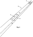
- FIG. 4 shows schematically another rod 3 of a supporting structure 2 according to the invention, which is also designed as a square tube and has recesses 4 on an upper side 11, via which connecting elements 1 can be introduced into an interior of the rod 3.
- a supporting structure 2 which is also designed as a square tube and has recesses 4 on an upper side 11, via which connecting elements 1 can be introduced into an interior of the rod 3.
- through holes 8 are provided here, via which connecting elements 1 introduced into the recesses 4 can be screwed to the square tube in order to form nodes.
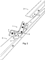
- figure 5 shows a rod 3 of a supporting structure 2 according to the invention corresponding to FIG 4 shown rod 3 with two connecting elements 1 inserted into the recess 4.
- the connecting elements 1 are arranged parallel and flat on the side surfaces 10 of the rod 3 and can be easily screwed to the rod 3 after insertion using screws 9 supplied from the outside.
- Two further rods 3, which are also formed by square tubes, can be connected to the connecting elements 1 in a corresponding manner via the parts of the connecting elements 1 protruding from the recess 4.
- Such a rod 3, which also has corresponding through holes 8, which correspond to holes 6 and nuts 7 of the connecting elements 1, is in figure 5 also shown.
- FIG. 6 shows schematically a node of a corresponding support structure 2, wherein a connecting element 1 is in turn connected on the underside to a rod 3 formed by a square tube, in that the connecting element 1 is introduced into the rod 3 via a recess 4 in a top side 11, i.e. analogously to the in figure 5 illustrated embodiment.
- Two further rods 3 are also designed as square tubes and are connected above to the connecting element 1 shown in dashed lines, in that coupling areas of the connecting element 1 are introduced into these rods 3 via open end faces and screwed to the rods 3 on the inside by screws 9 supplied from the outside.
- FIG. 7 shows a detail of a supporting structure 2 according to the invention approximately along a longitudinal axis of a rod 3 of the supporting structure 2.
- the connecting elements 1 are connected to the rod 3 by screws 9, the screws 9 also protruding through the side surfaces 10 of the rod 3 and screwed to nuts 7, which are also designed here as set nuts and are pressed into the base elements 5 of the connecting elements 1 will.
- a further rod 3 (not shown) can be connected to the rod 3 shown on two opposite side surfaces 10, for example by this further rod 3 being attached at the front to the top 11 of the rod 3 protruding parts of the connecting elements 1 is attached, after which the further rod 3 is screwed to the connecting elements 1 in an analogous manner.
- the recesses 4 in the upper side 11 of the rod 3 are here, as shown, adapted to a contour of the connecting element 1 to be inserted into the interior of the rod 3 , so that the recesses 4 also have recesses for the nuts 7 .
- Figures 8 to 10 show successive process steps in a method for connecting rods 3 of a supporting structure 2 with a connecting element 1 according to the invention.
- the rod 3 shown has two opposite recesses 4, through which a connecting element 1 protrudes on both sides from the rod 3, which is also designed here as a square tube.
- the connecting element 1 has an approximately cuboid shape, so that it can be guided from one side through both recesses 4 of the rod 3 in order to 10 to reach the position shown.
- the connecting element 1 has three bores 6 and on an underside, not shown, three nuts 7 corresponding to the bores 6 , which are also designed here as set nuts and are pressed into a base element 5 of the connecting element 1 .
- a central bore 6, on which a nut 7 is also arranged, is in 8 arranged at a position corresponding to a through hole 8 in the rod 3, so that the rod 3 as in 9 shown by means of a screw 9, which is inserted into the through hole 8, can be screwed to the connecting element 1, which is partially located in the rod 3.
- the screw 9 is designed here as a countersunk screw.
- versions with any other screw shape are also possible.
- FIG. 10 shows a situation in which one of the in 8 and 9 shown rod 3 protruding part of the connecting element 1 another rod 3 is attached.
- This further rod 3 also has a through hole 8 in order to be connected to the connecting element 1 and thus to the second rod 3 by means of a screw 9 which is guided through the through hole 8 .
- a further, corresponding connecting element 1 can be provided on a lower side surface 10 opposite the illustrated side surface 10 of the rod 3, which is at the top here, in order to connect three supports arranged at right angles to one another via two connecting elements 1 each, which are attached to opposite side surfaces 10 the carrier are arranged to connect.
- a connecting element 1 according to the invention enables supporting structures 2 to be produced in a particularly simple and at the same time process-reliable manner.
- the fasteners 1 cut by laser cutting and the holes 6 are introduced by laser cutting, high accuracy is also guaranteed at low cost.
- corresponding structures 2 can be produced in a particularly quick and at the same time robust manner.
Landscapes
- Engineering & Computer Science (AREA)
- General Engineering & Computer Science (AREA)
- Architecture (AREA)
- Mechanical Engineering (AREA)
- Physics & Mathematics (AREA)
- Electromagnetism (AREA)
- Civil Engineering (AREA)
- Structural Engineering (AREA)
- Mutual Connection Of Rods And Tubes (AREA)
Priority Applications (4)
| Application Number | Priority Date | Filing Date | Title |
|---|---|---|---|
| EP21158860.3A EP4050171B1 (fr) | 2021-02-24 | 2021-02-24 | Structure de support et son procédé de fabrication |
| PL21158860.3T PL4050171T3 (pl) | 2021-02-24 | 2021-02-24 | Konstrukcja nośna i sposób jej wytwarzania |
| DK21158860.3T DK4050171T3 (da) | 2021-02-24 | 2021-02-24 | Bærestruktur og fremgangsmåde til fremstilling af samme |
| SI202130048T SI4050171T1 (sl) | 2021-02-24 | 2021-02-24 | Nosilna konstrukcija in postopek za proizvodnjo le-te |
Applications Claiming Priority (1)
| Application Number | Priority Date | Filing Date | Title |
|---|---|---|---|
| EP21158860.3A EP4050171B1 (fr) | 2021-02-24 | 2021-02-24 | Structure de support et son procédé de fabrication |
Publications (2)
| Publication Number | Publication Date |
|---|---|
| EP4050171A1 true EP4050171A1 (fr) | 2022-08-31 |
| EP4050171B1 EP4050171B1 (fr) | 2023-04-26 |
Family
ID=74732699
Family Applications (1)
| Application Number | Title | Priority Date | Filing Date |
|---|---|---|---|
| EP21158860.3A Active EP4050171B1 (fr) | 2021-02-24 | 2021-02-24 | Structure de support et son procédé de fabrication |
Country Status (4)
| Country | Link |
|---|---|
| EP (1) | EP4050171B1 (fr) |
| DK (1) | DK4050171T3 (fr) |
| PL (1) | PL4050171T3 (fr) |
| SI (1) | SI4050171T1 (fr) |
Cited By (1)
| Publication number | Priority date | Publication date | Assignee | Title |
|---|---|---|---|---|
| EP4353653A1 (fr) * | 2022-10-10 | 2024-04-17 | TK Elevator Innovation and Operations GmbH | Dispositif de réception de charge destiné à recevoir une charge sur un profilé, en particulier dans un transporteur de passagers |
Citations (3)
| Publication number | Priority date | Publication date | Assignee | Title |
|---|---|---|---|---|
| JPH01322042A (ja) * | 1988-06-23 | 1989-12-27 | Kajima Corp | 閉鎖形断面柱と鉄骨梁との接合部構造 |
| JP2016121800A (ja) * | 2014-12-24 | 2016-07-07 | ピー.エス. テック カンパニー リミテッド | トルクシェアーボルト、固定ナット、及びこれを含むボルト組立体 |
| US10316508B1 (en) * | 2015-03-17 | 2019-06-11 | Thomas G. Hendry | Screen support assembly with wide lateral support efficiency |
-
2021
- 2021-02-24 SI SI202130048T patent/SI4050171T1/sl unknown
- 2021-02-24 PL PL21158860.3T patent/PL4050171T3/pl unknown
- 2021-02-24 EP EP21158860.3A patent/EP4050171B1/fr active Active
- 2021-02-24 DK DK21158860.3T patent/DK4050171T3/da active
Patent Citations (3)
| Publication number | Priority date | Publication date | Assignee | Title |
|---|---|---|---|---|
| JPH01322042A (ja) * | 1988-06-23 | 1989-12-27 | Kajima Corp | 閉鎖形断面柱と鉄骨梁との接合部構造 |
| JP2016121800A (ja) * | 2014-12-24 | 2016-07-07 | ピー.エス. テック カンパニー リミテッド | トルクシェアーボルト、固定ナット、及びこれを含むボルト組立体 |
| US10316508B1 (en) * | 2015-03-17 | 2019-06-11 | Thomas G. Hendry | Screen support assembly with wide lateral support efficiency |
Cited By (2)
| Publication number | Priority date | Publication date | Assignee | Title |
|---|---|---|---|---|
| EP4353653A1 (fr) * | 2022-10-10 | 2024-04-17 | TK Elevator Innovation and Operations GmbH | Dispositif de réception de charge destiné à recevoir une charge sur un profilé, en particulier dans un transporteur de passagers |
| WO2024078846A1 (fr) | 2022-10-10 | 2024-04-18 | Tk Elevator Innovation And Operations Gmbh | Dispositif de réception de charge destiné à recevoir une charge sur un profil, en particulier dans un dispositif de transport de personnes |
Also Published As
| Publication number | Publication date |
|---|---|
| EP4050171B1 (fr) | 2023-04-26 |
| DK4050171T3 (da) | 2023-07-10 |
| PL4050171T3 (pl) | 2023-08-21 |
| SI4050171T1 (sl) | 2023-08-31 |
Similar Documents
| Publication | Publication Date | Title |
|---|---|---|
| EP2093334B1 (fr) | Corps de raccordement notamment pour connecter deux éléments de construction en bois | |
| EP0136431A2 (fr) | Ossature en profilés | |
| EP3329060B1 (fr) | Procede de fabrication d'un rail de fixation et rail de fixation | |
| EP4050171B1 (fr) | Structure de support et son procédé de fabrication | |
| EP1388620B1 (fr) | Elément de connection pour un système de montage | |
| DE2162381A1 (de) | Eckverbinder fuer doppel-hohlprofilstreben | |
| EP0628734A1 (fr) | Dispositif de fixation pour relier de manière amovible un tube polygonal, en particulier un tube à profil rectangulaire | |
| EP2827043B1 (fr) | Procédé de fabrication d'un rail double et rail double | |
| DE69517964T2 (de) | Rahmen | |
| WO2022242964A1 (fr) | Support de structure | |
| DE29612053U1 (de) | Bewehrungsvorrichtung | |
| EP4187036B1 (fr) | Élément porteur, ainsi que procédé de fabrication d'un tel élément porteur | |
| EP1743863A1 (fr) | Elément de connexion | |
| EP4359623B1 (fr) | Truelle de lissage à longue durée de vie | |
| DE104838C (fr) | ||
| EP3130716B1 (fr) | Panneau de mur et systeme de panneaux de mur pour la construction de stand d'exposition | |
| EP3947887B1 (fr) | Raccord angulaire métallique | |
| EP3561199A1 (fr) | Élément de raccordement pour coffrages et procédé de raccordement du coffrage | |
| EP1210998A2 (fr) | Procédé et dispositif pour la fabrication d'un profil métallique | |
| EP4272885A1 (fr) | Procédé de fixation d'un corps femelle dans un corps tubulaire | |
| DE3405631C2 (fr) | ||
| DE3874895T2 (de) | Verfahren zum befestigen einer traverse auf einer seitenstuetze, insbesondere in einem kabelgestell und verbindungsstelle auf diese weise geformt sowie ein profilstab fuer diese verbindung. | |
| DE20315497U1 (de) | Vorrichtung zur Aufnahme von Werkstücken | |
| EP4079423A1 (fr) | Procédé de fabrication d'un rail de guidage tubulaire à glissière et rail de guidage doté d'une glissière | |
| EP4491815A1 (fr) | Dispositif de positionnement et procédé de fixation d'une deuxième partie de construction sur une première partie de construction |
Legal Events
| Date | Code | Title | Description |
|---|---|---|---|
| STAA | Information on the status of an ep patent application or granted ep patent |
Free format text: STATUS: EXAMINATION IS IN PROGRESS |
|
| PUAI | Public reference made under article 153(3) epc to a published international application that has entered the european phase |
Free format text: ORIGINAL CODE: 0009012 |
|
| 17P | Request for examination filed |
Effective date: 20211117 |
|
| AK | Designated contracting states |
Kind code of ref document: A1 Designated state(s): AL AT BE BG CH CY CZ DE DK EE ES FI FR GB GR HR HU IE IS IT LI LT LU LV MC MK MT NL NO PL PT RO RS SE SI SK SM TR |
|
| GRAP | Despatch of communication of intention to grant a patent |
Free format text: ORIGINAL CODE: EPIDOSNIGR1 |
|
| STAA | Information on the status of an ep patent application or granted ep patent |
Free format text: STATUS: GRANT OF PATENT IS INTENDED |
|
| GRAS | Grant fee paid |
Free format text: ORIGINAL CODE: EPIDOSNIGR3 |
|
| RIC1 | Information provided on ipc code assigned before grant |
Ipc: E04C 3/08 20060101ALN20230213BHEP Ipc: E04C 3/04 20060101ALN20230213BHEP Ipc: E04B 1/58 20060101ALN20230213BHEP Ipc: F16B 37/04 20060101ALN20230213BHEP Ipc: F16B 7/18 20060101ALI20230213BHEP Ipc: E04B 1/19 20060101AFI20230213BHEP |
|
| GRAA | (expected) grant |
Free format text: ORIGINAL CODE: 0009210 |
|
| STAA | Information on the status of an ep patent application or granted ep patent |
Free format text: STATUS: THE PATENT HAS BEEN GRANTED |
|
| INTG | Intention to grant announced |
Effective date: 20230302 |
|
| AK | Designated contracting states |
Kind code of ref document: B1 Designated state(s): AL AT BE BG CH CY CZ DE DK EE ES FI FR GB GR HR HU IE IS IT LI LT LU LV MC MK MT NL NO PL PT RO RS SE SI SK SM TR |
|
| REG | Reference to a national code |
Ref country code: GB Ref legal event code: FG4D Free format text: NOT ENGLISH |
|
| REG | Reference to a national code |
Ref country code: CH Ref legal event code: EP |
|
| REG | Reference to a national code |
Ref country code: DE Ref legal event code: R096 Ref document number: 502021000597 Country of ref document: DE |
|
| REG | Reference to a national code |
Ref country code: AT Ref legal event code: REF Ref document number: 1562902 Country of ref document: AT Kind code of ref document: T Effective date: 20230515 |
|
| REG | Reference to a national code |
Ref country code: IE Ref legal event code: FG4D Free format text: LANGUAGE OF EP DOCUMENT: GERMAN |
|
| REG | Reference to a national code |
Ref country code: DK Ref legal event code: T3 Effective date: 20230704 |
|
| REG | Reference to a national code |
Ref country code: NL Ref legal event code: FP |
|
| REG | Reference to a national code |
Ref country code: LT Ref legal event code: MG9D |
|
| REG | Reference to a national code |
Ref country code: DE Ref legal event code: R082 Ref document number: 502021000597 Country of ref document: DE Representative=s name: ZEUNER SUMMERER STUETZ, PATENT- UND RECHTSANWA, DE |
|
| PG25 | Lapsed in a contracting state [announced via postgrant information from national office to epo] |
Ref country code: SE Free format text: LAPSE BECAUSE OF FAILURE TO SUBMIT A TRANSLATION OF THE DESCRIPTION OR TO PAY THE FEE WITHIN THE PRESCRIBED TIME-LIMIT Effective date: 20230426 Ref country code: PT Free format text: LAPSE BECAUSE OF FAILURE TO SUBMIT A TRANSLATION OF THE DESCRIPTION OR TO PAY THE FEE WITHIN THE PRESCRIBED TIME-LIMIT Effective date: 20230828 Ref country code: NO Free format text: LAPSE BECAUSE OF FAILURE TO SUBMIT A TRANSLATION OF THE DESCRIPTION OR TO PAY THE FEE WITHIN THE PRESCRIBED TIME-LIMIT Effective date: 20230726 Ref country code: ES Free format text: LAPSE BECAUSE OF FAILURE TO SUBMIT A TRANSLATION OF THE DESCRIPTION OR TO PAY THE FEE WITHIN THE PRESCRIBED TIME-LIMIT Effective date: 20230426 |
|
| PG25 | Lapsed in a contracting state [announced via postgrant information from national office to epo] |
Ref country code: RS Free format text: LAPSE BECAUSE OF FAILURE TO SUBMIT A TRANSLATION OF THE DESCRIPTION OR TO PAY THE FEE WITHIN THE PRESCRIBED TIME-LIMIT Effective date: 20230426 Ref country code: LV Free format text: LAPSE BECAUSE OF FAILURE TO SUBMIT A TRANSLATION OF THE DESCRIPTION OR TO PAY THE FEE WITHIN THE PRESCRIBED TIME-LIMIT Effective date: 20230426 Ref country code: LT Free format text: LAPSE BECAUSE OF FAILURE TO SUBMIT A TRANSLATION OF THE DESCRIPTION OR TO PAY THE FEE WITHIN THE PRESCRIBED TIME-LIMIT Effective date: 20230426 Ref country code: IS Free format text: LAPSE BECAUSE OF FAILURE TO SUBMIT A TRANSLATION OF THE DESCRIPTION OR TO PAY THE FEE WITHIN THE PRESCRIBED TIME-LIMIT Effective date: 20230826 Ref country code: HR Free format text: LAPSE BECAUSE OF FAILURE TO SUBMIT A TRANSLATION OF THE DESCRIPTION OR TO PAY THE FEE WITHIN THE PRESCRIBED TIME-LIMIT Effective date: 20230426 Ref country code: GR Free format text: LAPSE BECAUSE OF FAILURE TO SUBMIT A TRANSLATION OF THE DESCRIPTION OR TO PAY THE FEE WITHIN THE PRESCRIBED TIME-LIMIT Effective date: 20230727 |
|
| PG25 | Lapsed in a contracting state [announced via postgrant information from national office to epo] |
Ref country code: FI Free format text: LAPSE BECAUSE OF FAILURE TO SUBMIT A TRANSLATION OF THE DESCRIPTION OR TO PAY THE FEE WITHIN THE PRESCRIBED TIME-LIMIT Effective date: 20230426 |
|
| PG25 | Lapsed in a contracting state [announced via postgrant information from national office to epo] |
Ref country code: SK Free format text: LAPSE BECAUSE OF FAILURE TO SUBMIT A TRANSLATION OF THE DESCRIPTION OR TO PAY THE FEE WITHIN THE PRESCRIBED TIME-LIMIT Effective date: 20230426 |
|
| REG | Reference to a national code |
Ref country code: DE Ref legal event code: R097 Ref document number: 502021000597 Country of ref document: DE |
|
| PG25 | Lapsed in a contracting state [announced via postgrant information from national office to epo] |
Ref country code: SM Free format text: LAPSE BECAUSE OF FAILURE TO SUBMIT A TRANSLATION OF THE DESCRIPTION OR TO PAY THE FEE WITHIN THE PRESCRIBED TIME-LIMIT Effective date: 20230426 Ref country code: SK Free format text: LAPSE BECAUSE OF FAILURE TO SUBMIT A TRANSLATION OF THE DESCRIPTION OR TO PAY THE FEE WITHIN THE PRESCRIBED TIME-LIMIT Effective date: 20230426 Ref country code: RO Free format text: LAPSE BECAUSE OF FAILURE TO SUBMIT A TRANSLATION OF THE DESCRIPTION OR TO PAY THE FEE WITHIN THE PRESCRIBED TIME-LIMIT Effective date: 20230426 Ref country code: EE Free format text: LAPSE BECAUSE OF FAILURE TO SUBMIT A TRANSLATION OF THE DESCRIPTION OR TO PAY THE FEE WITHIN THE PRESCRIBED TIME-LIMIT Effective date: 20230426 |
|
| PLBE | No opposition filed within time limit |
Free format text: ORIGINAL CODE: 0009261 |
|
| STAA | Information on the status of an ep patent application or granted ep patent |
Free format text: STATUS: NO OPPOSITION FILED WITHIN TIME LIMIT |
|
| 26N | No opposition filed |
Effective date: 20240129 |
|
| PG25 | Lapsed in a contracting state [announced via postgrant information from national office to epo] |
Ref country code: BG Free format text: LAPSE BECAUSE OF FAILURE TO SUBMIT A TRANSLATION OF THE DESCRIPTION OR TO PAY THE FEE WITHIN THE PRESCRIBED TIME-LIMIT Effective date: 20230426 |
|
| PG25 | Lapsed in a contracting state [announced via postgrant information from national office to epo] |
Ref country code: BG Free format text: LAPSE BECAUSE OF FAILURE TO SUBMIT A TRANSLATION OF THE DESCRIPTION OR TO PAY THE FEE WITHIN THE PRESCRIBED TIME-LIMIT Effective date: 20230426 |
|
| PG25 | Lapsed in a contracting state [announced via postgrant information from national office to epo] |
Ref country code: IE Free format text: LAPSE BECAUSE OF NON-PAYMENT OF DUE FEES Effective date: 20240224 |
|
| PG25 | Lapsed in a contracting state [announced via postgrant information from national office to epo] |
Ref country code: IE Free format text: LAPSE BECAUSE OF NON-PAYMENT OF DUE FEES Effective date: 20240224 |
|
| PG25 | Lapsed in a contracting state [announced via postgrant information from national office to epo] |
Ref country code: CY Free format text: LAPSE BECAUSE OF FAILURE TO SUBMIT A TRANSLATION OF THE DESCRIPTION OR TO PAY THE FEE WITHIN THE PRESCRIBED TIME-LIMIT; INVALID AB INITIO Effective date: 20210224 |
|
| PG25 | Lapsed in a contracting state [announced via postgrant information from national office to epo] |
Ref country code: HU Free format text: LAPSE BECAUSE OF FAILURE TO SUBMIT A TRANSLATION OF THE DESCRIPTION OR TO PAY THE FEE WITHIN THE PRESCRIBED TIME-LIMIT; INVALID AB INITIO Effective date: 20210224 |
|
| PG25 | Lapsed in a contracting state [announced via postgrant information from national office to epo] |
Ref country code: TR Free format text: LAPSE BECAUSE OF FAILURE TO SUBMIT A TRANSLATION OF THE DESCRIPTION OR TO PAY THE FEE WITHIN THE PRESCRIBED TIME-LIMIT Effective date: 20230426 |
|
| REG | Reference to a national code |
Ref country code: CH Ref legal event code: U11 Free format text: ST27 STATUS EVENT CODE: U-0-0-U10-U11 (AS PROVIDED BY THE NATIONAL OFFICE) Effective date: 20260301 |
|
| PGFP | Annual fee paid to national office [announced via postgrant information from national office to epo] |
Ref country code: LU Payment date: 20260218 Year of fee payment: 6 Ref country code: NL Payment date: 20260218 Year of fee payment: 6 |
|
| PGFP | Annual fee paid to national office [announced via postgrant information from national office to epo] |
Ref country code: GB Payment date: 20260220 Year of fee payment: 6 |
|
| PGFP | Annual fee paid to national office [announced via postgrant information from national office to epo] |
Ref country code: MC Payment date: 20260220 Year of fee payment: 6 |
|
| PGFP | Annual fee paid to national office [announced via postgrant information from national office to epo] |
Ref country code: DK Payment date: 20260220 Year of fee payment: 6 Ref country code: DE Payment date: 20260218 Year of fee payment: 6 |
|
| PGFP | Annual fee paid to national office [announced via postgrant information from national office to epo] |
Ref country code: AT Payment date: 20260121 Year of fee payment: 6 |
|
| PGFP | Annual fee paid to national office [announced via postgrant information from national office to epo] |
Ref country code: BE Payment date: 20260218 Year of fee payment: 6 Ref country code: IT Payment date: 20260224 Year of fee payment: 6 |
|
| PGFP | Annual fee paid to national office [announced via postgrant information from national office to epo] |
Ref country code: FR Payment date: 20260219 Year of fee payment: 6 |
|
| PGFP | Annual fee paid to national office [announced via postgrant information from national office to epo] |
Ref country code: CZ Payment date: 20260217 Year of fee payment: 6 Ref country code: CH Payment date: 20260301 Year of fee payment: 6 |
|
| PGFP | Annual fee paid to national office [announced via postgrant information from national office to epo] |
Ref country code: PL Payment date: 20260212 Year of fee payment: 6 |
|
| PGFP | Annual fee paid to national office [announced via postgrant information from national office to epo] |
Ref country code: SI Payment date: 20260212 Year of fee payment: 6 |